

ICP OMF112K14A, OMV112K14A Installation Instructions And Homeowner's Manual
MODEL:
OMF112K14A
OMV112K14A
DNS-1225A
US C
MULTIPOSITION
OIL FIRED FURNACE
INSTALLER / SERVICE TECHNICIAN:
USE THE INFORMATION IN THIS MANUAL FOR THE
INSTALLATION / SERVICING OF THE FURNACE AND KEEP
THE DOCUMENT NEAR THE UNIT FOR FUTURE
REFERENCE.
HOMEOWNER:
PLEASE KEEP THIS MANUAL NEAR THE FURNACE FOR
FUTURE REFERENCE.
Printed on 100% recycled paper 2009-12-07 X40165 Rev. B
Attention:
Do not tamper with the unit or its
controls. Call a qualified service
technician.
Manufactured by:
UTC Canada Corporation
ICP Division
445 014101 00

445 01 4101 00
TABLE OF CONTENTS
1 SAFETY REGULATIONS ..................................................................................3
1.1 SAFETY LABELING AND WARNING SIGNS .............................................................................................3
1.2 IMPORTANT INFORMATION.....................................................................................................................3
1.3 DETECTION SYSTEMS.............................................................................................................................3
1.4 DANGER OF FREEZING............................................................................................................................3
2 INSTALLATION ................................................................................................. 4
2.1 POSITIONING THE FURNACE ..................................................................................................................4
2.2 CONFIGURATIONS (FIGURES 1 & 2) ..........................................................................................................4
2.3 ELECTRICAL SYSTEM (FIGURES 3 & 4).....................................................................................................5
2.4 INSTALLATION OF THE THERMOSTAT ...................................................................................................5
2.5 INSTALLATION OF THE BURNER.............................................................................................................6
2.6 VENTING ...................................................................................................................................................6
2.7 BLOCKED VENT SHUT-OFF DEVICE (BVSO) FOR CHIMNEY VENTING.................................................7
2.8 COMBUSTION AIR SUPPLY AND VENTILATION......................................................................................7
2.9 OIL TANK...................................................................................................................................................8
2.10 DUCTING...................................................................................................................................................8
2.11 SUPPLY AIR ADJUSTMENTS (4 SPEED MOTORS).................................................................................8
2.12 SUPPLY AIR ADJUSTMENTS (ECM VARIABLE SPEED MOTORS).........................................................9
2.13 INSTALLATION OF ACCESSORIES..........................................................................................................9
3 OPERATION .................................................................................................... 10
3.1 START-UP................................................................................................................................................10
3.2 OPERATING SEQUENCE OIL HEATING MODE .....................................................................................10
3.3 CHECKS AND ADJUSTMENTS...............................................................................................................10
4 MAINTENANCE...............................................................................................12
4.1 CLEANING THE HEAT EXCHANGER......................................................................................................12
4.2 CLEANING THE BLOCKED VENT SHUT-OFF DEVICE (BVSO)..............................................................12
4.4 REPLACING THE NOZZLE......................................................................................................................12
4.5 REPLACING THE OIL FILTER .................................................................................................................12
4.6 REPLACING THE AIR FILTER.................................................................................................................12
5 FURNACE INFORMATION.............................................................................. 13
TABLE 1 - TECHNICAL SPECIFICATIONS................................................................................................................. 14
TABLE 2 - AIR FLOW, UNITS WITH ½ HP ECM MOTEUR ......................................................................................... 15
TABLE 3 - AIR FLOW, UNITS WITH ½ HP PSC MOTEUR.......................................................................................... 16
TABLE 4 - MINIMUM CLEARANCES FROM COMBUSTIBLE MATÉRIAL................................................................... 16
FIGURE 5 - DIMENSIONS..............................................................................................................................................17
FIGURE 6 - WIRING DIAGRAM, DD, 4 SPEED PSC MOTOR....................................................................................... 18
FIGURE 7 - WIRING DIAGRAM, DD, VARIABLE SPEED ECM MOTEUR.................................................................... 19
EXPLODED VIEWS OF COMPONENTS AND PARTS LISTS................................................................................20 to 23
TABLES AND FIGURES
2
445 01 4101 00
1 SAFETY REGULATIONS
1.1 SAFETY LABELING AND
WARNING SIGNS
The words DANGER, WARNING AND CAUTION are used
to identify the levels of seriousness of certain hazards. It is
important that you understand their meaning. You will
notice these words in the manual as follows:
DANGER
Immediate hazards that WILL result in death, serious
bodily injury and/or property damage.
WARNING
Hazards or unsafe practices that CAN result in death,
bodily injury and/or property damage.
CAUTION
Hazards or unsafe practices that CAN result in bodily injury
and/or property damage.
1.2 IMPORTANT INFORMATION
WARNING
Non-observance of the safety regulations outlined in
this manual will potentially lead to consequences
resulting in death, serious bodily injury and/or
property damage.
a) It is the homeowner’s responsibility to engage a
qualified technician for the installation and
subsequent servicing of this furnace;
b) Do not use this furnace if any part of it w as under
water. Call a qualified service technician
immediately to assess the damage and to replace
all critical parts that were in contact with water;
c) Do not store gasoline or any other flammable
substances, such as paper, carton, etc. near the
furnace;
d) This furnace is designed for use with #1 or #2
heating oil only. The use of gasoline, motor oil or
any other oil containing gasoline is prohibited;
e) Never block or otherwise obstruct the filter and/or
return air openings;
f) Ask the technician installing your furnace to show
and explain to you the following items:
i) The main disconnect switch;
ii) The shut-off valve on the oil tank;
iii) The oil filter and how to change it (once a
year);
iv) The air filter and how to change it (check
monthly and clean or replace if necessary.)
g) Before calling for service, be sure to have the
information page of your manual close by in order
to be able to provide the contractor with the
required information, such as the model and
serial numbers of the furnace.
WARNING
Installations and repairs performed by unqualified
persons can result in hazards to them and to others.
Installations must conform to local codes or, in the
absence of same, to codes of the country having
jurisdiction.
The information contained in this manual is intended
for use by a qualified technician, familiar with safety
procedures and who is equipped with the proper tools
and test instruments.
Failure to carefully read and follow all instructions in
this manual can result in death, bodily injury and/or
property damage.
1.3 DETECTION SYSTEMS
It is recommended that carbon monoxide detectors be
installed wherever oil or gas fired heaters are used.
Carbon monoxide can cause bodily harm or death. For
this reason, agency approved carbon monoxide detectors
should be installed in your residence and properly
maintained to warn of dangerously high carbon monoxide
levels.
There are several sources of possible smoke and flames
in a residence. Smoke and flames can cause bodily harm
or death. For this reason, agency approved smoke
detectors should be installed in your residence and
properly maintained, to warn early on, of a potentially
dangerous fire. Also, the house should be equipped with
approved and properly maintained fire extinguishers.
Your unit is equipped with safety devices that can prevent
it from functioning when anomalies are detected such as a
blocked venting system.
1.4 DANGER OF FREEZING
If your furnace is shut down during the cold weather
season, water pipes may freeze, burst and cause serious
water damage. Turn off the water supply and bleed the
pipes.
If the heater is left unattended during the cold weather
season, take the following precautions:
a. Close the main water valve in the house and purge
the pipes if possible. Open all the faucets in the
house;
b. Ask someone to frequently check the house during
the cold weather season to make sure that there is
sufficient heat to prevent the pipes from freezing. Tell
this person to call an emergency number if required.
CAUTION
3
445 01 4101 00
2 INSTALLATION
This furnace is a true multi-position unit, in that it will
function in an upflow, downflow or horizontal configuration
to the left or the right. Only a few modifications are
required during installation to change from one position to
another. The unit is shipped in the upflow configuration
and instructions as to how to change to the other
positions are included in this manual.
The unit is shipped with a burner and its controls. It
requires a 115VAC power supply to the control panel and
thermostat hook-up as shown on the wiring diagram, one
or more oil line connections, suitable ductwork and
connection to a properly sized vent.
All local and national code requirements governing the
installation of oil burning equipment, wiring and the flue
connection MUST be followed. Some of the codes that
may apply are:
CSA B139: Installation code for oil burning
equipment.
ANSI/NFPA 31: Installation of oil burning equipment.
ANSI/NFPA 90B: Warm air heating and air conditioning
systems.
ANSI/NFPA 211: Chimneys, Fireplaces, Vents and solid
fuel burning appliances.
ANSI/NFPA 70: National Electrical Code.
CSA C22.1 or CSA C22.10:
Canadian Electrical Code.
Only the latest issues of these codes may be used.
2.1 POSITIONING THE FURNACE
WARNING
Fire and explosion hazard.
The furnace must be installed in a level position, never
where it will slope toward the front.
Do not store or use gasoline or any other flammable
substances near the furnace.
Non-observance of these instructions will potentially
result in death, bodily injury and/or property damage.
CAUTION
This furnace is not watertight and is not designed for
outdoor installation. It must be installed in such a manner
as to protect its electrical components from water.
Outdoor installation will lead to a hazardous electrical
condition and to premature failure of the equipment.
The minimum clearances from combustible material
for each of the positions are specified in Table 4.
If the furnace is installed in a basement or on a dirt floor,
in a crawl space for example, it is recommended to install
the unit on a cement base 2.5 cm to 5.0 cm (1" to 2")
thick.
DNS-1227A
The unit must be installed in an area where the ambient
and return air temperatures are above 15°C (60°F). In
addition, the furnace should be installed as closely as
possible to the vent, so that the connections are direct
and kept to a minimum. The heater should also be
located close to the centre of the air distribution system.
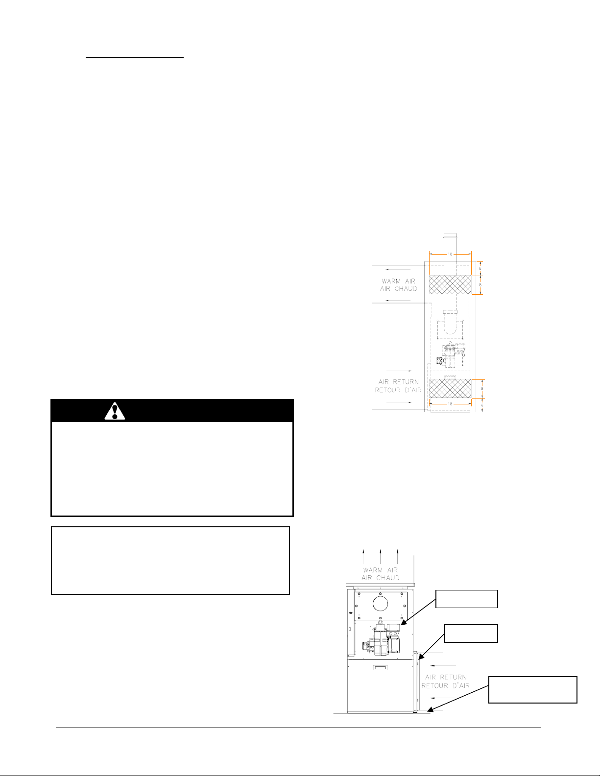
2.1.1
Installation in an enclosure
The unit can be installed in an enclosure such as a
closet. However, 2 ventilation openings are required for
combustion air. The openings should be located in front
of the furnace approximately 15 cm (6") above the floor
and 15 cm (6") below the ceiling. Figure 1 indicates the
minimum dimensions required and the location of the
openings.
Figure 1
Location and dimensions of
ventilation air openings in a closet door
2.2 CONFIGURATIONS
2.2.1 Upflow Installation
The return air opening may be located on either side of
the furnace. Care should be taken not to damage the
wires inside, while cutting the opening. Install the filter
rack supplied with the unit according to the instructions
provided with it. It is also recommended to install the
blower door before handling or moving the unit. Refer to
Figure 2 for additional details.
Figure 2
Burner position
Filter 20X24
Combustible or noncombustible floor
4
445 01 4101 00
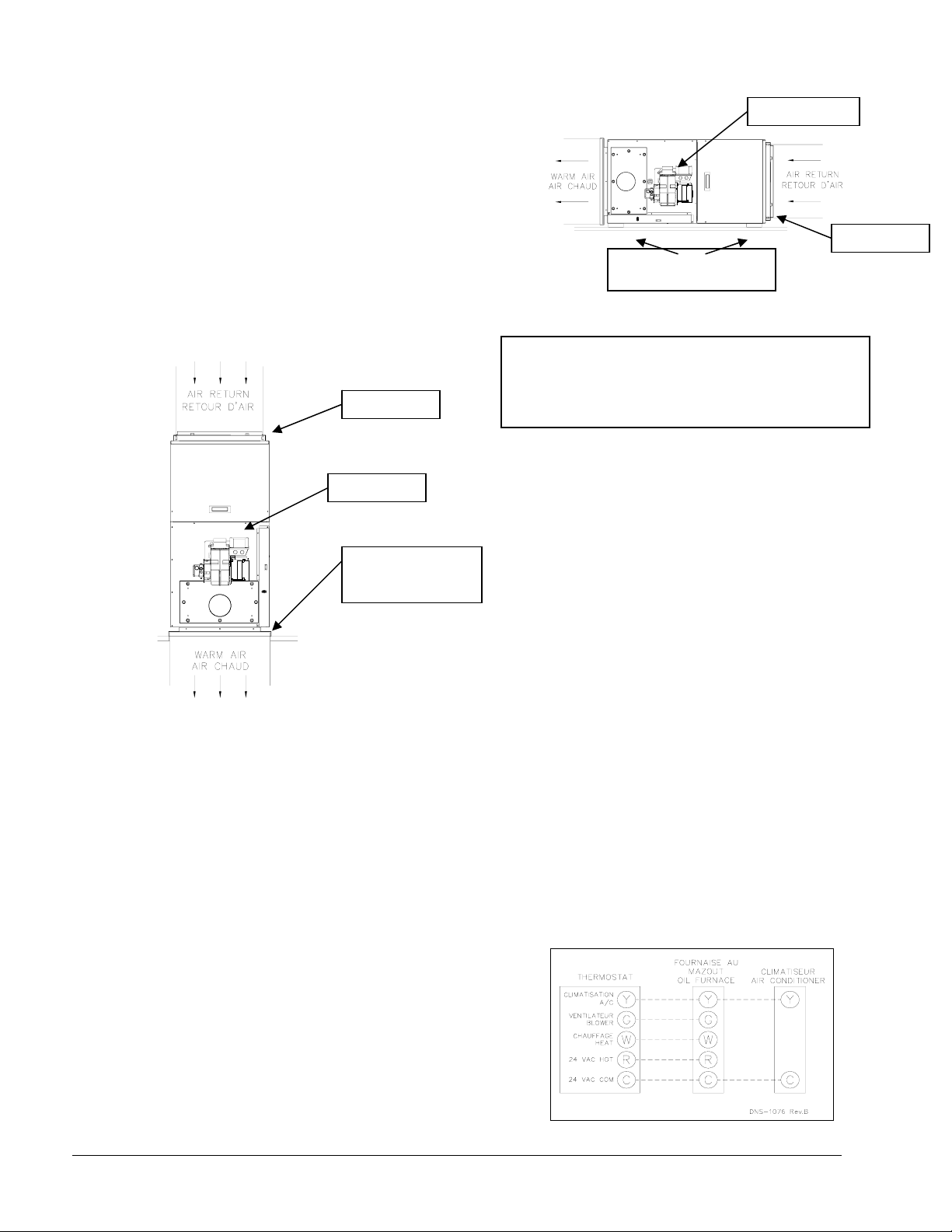
2.2.2 Downflow Installation
When the furnace is installed in the downflow position on a
combustible floor, the clearances from combustibles must
be adhered to. The downflow base DFB-103 or
KLASB0901DET can be used to ensure these clearances.
Refer to Figure 3 and the installation instructions provided
with the base.
The burner must always be installed in the same manner,
regardless of the discharge position of the furnace. Refer
to Figure 3 for additional details.
Figure 3
2.2.3 Horizontal Installation
When the furnace is installed in the horizontal position,
either suspended or on a combustible floor with a choice of
right or left discharge, the clearances from combustible
material must be adhered to. If the unit is installed on a
combustible floor, the horizontal floor base HFB-101 or
KLASB0701DET can be used to ensure these clearances.
Refer to the instructions supplied with the base.
The burner must always be installed in the same manner,
regardless of the discharge position of the furnace. Refer
to Figure 4 for additional details.
Burner position
Filter 20 x 24
Downflow base is
required for
combustible floor
DNS-1227A
Horizontal floor base required
for combustible floor
Burner position
Filter 20 x 24
DNS-1227A
2.3 ELECTRICAL SYSTEM
CAUTION
The exterior of the unit must have an uninterrupted
ground to minimize the risk of bodily harm, if ever an
electrical problem develops. A green ground screw is
supplied with the control box for that purpose.
The appliance must be installed in accordance with the
current ANSI/NFPA 70 National Electrical Code, CSA
C22.1 Canadian Electrical Code Part 1 and/or local
codes.
The control system depends on the correct polarity of
the power supply. Connect “HOT” wire (H) and
“NEUTRAL” wire (N) as shown in Figures 6 and 7, p. 18
and 19.
A separate line voltage supply should be used, with
fused disconnect switch or circuit breaker, between the
main power panel and the unit.
Only copper wire may be used for the 115V circuit on
this unit. If wires need to be changed, the replacements
must have the same temperature resistance as the
originals.
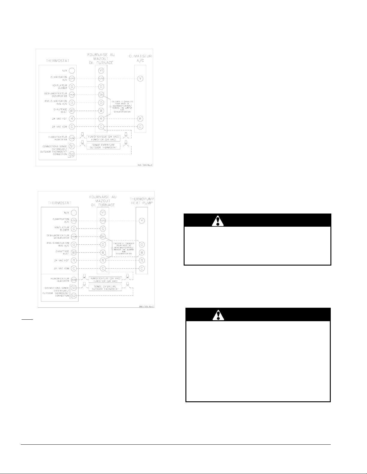
2.4 INSTALLATION OF THE
THERMOSTAT
A thermostat must be installed to control the
temperature of the area to be heated. Follow the
instructions supplied with the thermostat. Also refer to
the wiring diagrams provided with the heating/air
conditioning unit. The connections must be made as
indicated on the following diagrams and the wiring
diagrams, p. 18 and 19.
Thermostat Wiring
Heating and Air Conditioning
Figure 4
with 4-speed motor
5
445 01 4101 00
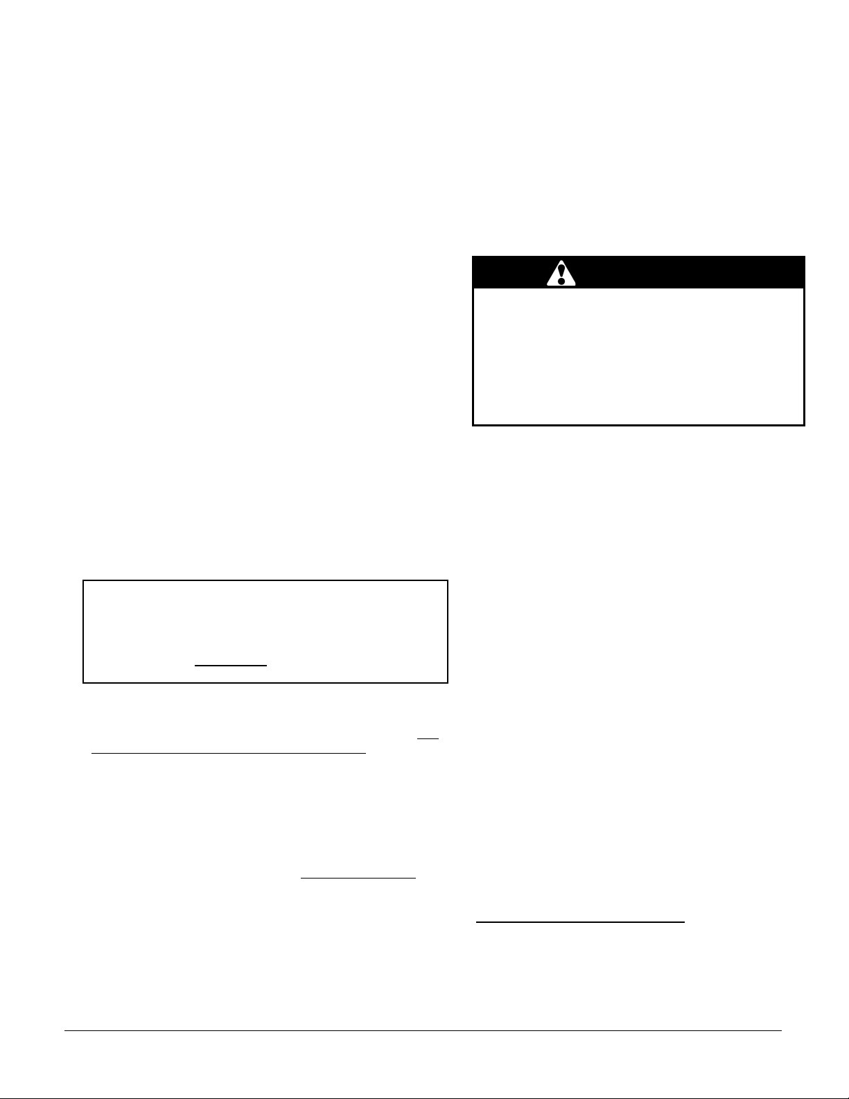
Thermostat Wiring
Heating and Air Conditioning
with ECM variable speed motor
Thermostat Wiring
Heating and Air Conditioning/Heat pump
with ECM variable speed motor
Note: On units with 2 stage cooling or heat pump, terminal Y1
must be used. When Y1 on the electronic control receives a 24
VAC signal, the air flow is reduced by 20%. Do not use
terminal Y1 with a single stage cooling or heat pump.
2.5 INSTALLATION OF THE BURNER
Refer to the burner manufacturer’s instructions. Also, the
burner must be installed always in the same way
independently of the furnace orientation.
1. Position the mounting gasket between the mounting
flange and the burner mounting plate. Align the holes in
the burner mounting plate with the studs on the mounting
flange and bolt securely in place.
2. Remove the burner drawer assembly or the air tube
assembly;
3. Install the nozzle (refer to Technical Specifications, p.14);
4. Check the electrode settings;
5. Make the electrical connections;
6. Complete oil line connections.
2.5.1 Nozzles
The burner comes equipped with an appropriate nozzle.
However, if another size or a replacement nozzle is
required, use the manufacturer’s recommended spray
angle and type a shown in Table 1 and based on a pump
pressure of 100 psi.
Always select nozzle sizes by working back from the
desired flow rate at operating pressure and not the nozzle
marking.
2.5.2 Air and Turbulator Settings
Before starting the burner for the first time, adjust the air
and turbulator settings to those listed in this manual. Once
the burner becomes operational, final adjustments will be
required. Refer to section 3 of this manual.
2.5.3 Post purge delay adjustment
The post purge delay on the oil-fired burners is factory set
to zero second. This delay is applicable for all installations
with chimney venting. For heating units installed with side
wall venting and a burner equipped with this feature, the
post purge delay must be set to 15 seconds. Refer to the
burner control instruction manual and markings for proper
adjustment of the post purge delay.
2.6 VENTING
WARNING
Poisonous carbon monoxide gas, fire and explosion
hazard.
Read and follow all instructions in this section.
Failure to properly vent this furnace can result in in
death, bodily injury and/or property damage.
To ensure the safe and proper functioning of an oil
furnace, it must always be connected to a flue with
sufficient draft or to an approved side-wall venting system.
In addition, it is strongly recommended to perform a
complete inspection of all the existing venting systems.
WARNING
Poisonous carbon monoxide gas hazard.
Never install a hand operated damper in the vent pipe.
However, any Underwriters Laboratories listed,
electrically operated automatic type vent damper may
be installed if desired. Be sure to follow the
instructions provided with vent damper. Also, read
and follow all instructions in this section of the
manual.
Failure to properly vent this furnace or other
appliances can result in death, bodily injury and/or
property damage.
6
445 01 4101 00
2.6.1 Masonry chimney
This furnace can be vented into an existing masonry chimney.
However, the unit must not be vented into a chimney into
which a solid fuel burning furnace is already being vented.
Before venting this furnace into a chimney, its condition must
be checked and repairs made, if necessary. Also, the chimney
lining and dimensions must conform to local and national
codes.
2.6.2 Factory Built Chimneys
Oil fired furnaces are approved for use with “L” type vents. The
unit may also be used with an approved chimney of proper
dimensions and temperature ratings as specified in the
installation code. Refer to chimney manufacturer’s instructions
for proper installation.
2.6.3 Draft Regulator
This unit may be installed with or without a draft regulator.
However, it is recommended that a draft regulator be installed
in cases where the draft is either high or variable due to
external conditions. Follow the instructions provided with the
regulator.
2.6.4 Side-wall Venting
The heating unit is approved for side-wall venting. This system
is comprised of a model VTK-098 / KLAVT0101DET side-wall
venter and a 4” insulated vent pipe, model IFV098 /
KLAFVxx01DET. Refer to the installation instructions provided
with the venting system.
2.7 BLOCKED VENT SHUT-OFF DEVICE
(BVSO) FOR CHIMNEY VENTING
CAUTION
It is imperative that this device be installed by a qualified service
technician.
A positive pressure venting system (Sealed Combustion System
or Direct Vent) MUST NOT use the BVSO. Follow the
instructions supplied with the venting system.
This device is designed to detect the insufficient evacuation of
combustion gases in the event of a vent blockage. In such a
case the thermal switch will shut down the oil burner. The
device will then need to be re-armed MANUALLY.
Refer to the detailed instructions and wiring diagrams supplied
with the BVSO for the installation and wiring procedures. The
length of wires supplied with the unit is such that the safety
device must be installed between the flue outlet of the
appliance and the draft regulator, as indicated in the
instructions.
It is also essential that the BVSO be maintained annually. For
more details refer to the instructions supplied with the device
itself, as well as Section 3. of this Manual.
2.7.1 BVSO Performance Test
The purpose of the following test is to check that the electrical
outlet on the furnace, designated to the BVSO, is functional.
7
1. Start up the burner;
2. Remove the three-pole plug from the BVSO outlet on
the furnace;
3. The burner must shut-off immediately, while the
blower continues to run to the end of the cool-down
cycle.
If the test is not in line with the above, call a QUALIFIED
SERVICE TECHNICIAN.
2.8 COMBUSTION AIR SUPPLY
VENTILATION
AND
WARNING
Poisonous carbon monoxide gas hazard.
Comply with NFPA 31 (U.S.) and CSA B139 (Canada)
standards for the installation of Oil Burning
Equipment and applicable provisions of local building
codes to provide combustion and ventilation air.
Failure to provide adequate combustion and
ventilation air can result in death, bodily injury and/or
property damage.
Oil furnaces must have an adequate supply of combustion
air. It is common practice to assume that older homes
have sufficient infiltration to accommodate the combustion
air requirement for the furnace. However, home
improvements such as new windows, doors, and weather
stripping have drastically reduced the volume of air
infiltration into the home.
Refer to oil furnace installation codes relative to
combustion and ventilation air requirements. Consult
Section 2.2 in this manual, specifically for units installed in
an enclosed space.
Home air exhausters are common. Bathroom and kitchen
fans, power vented clothes dryers and water heaters all
tend to create a negative pressure condition in the home.
Should this occur the chimney becomes less and less
effective and can easily downdraft. In certain cases,
mechanically supplied air, by way of a blower, interlocked
with the unit, is necessary. It is the installer’s responsibility
to check that.
2.8.1 Contaminated Combustion Air
Installations in certain areas or types of structures will
increase the exposure to chemicals or halogens that may
harm the furnace. These conditions will require that only
outside air be used for combustion.
The following areas or types of structures may contain or
be exposed to certain substances, potentially requiring
outside air for combustion:
a. Commercial buildings;
b. Buildings with indoor pools;
c. Furnaces installed near chemical storage areas.
Exposure to the following substances:
a. Permanent wave chemicals for hair;
b. Chlorinated waxes and cleaners;
c. Chlorine based swimming pool chemicals;
d. Water softening chemicals;
e. De-icing salts or chemicals;
f. Carbon tetrachloride;
 Loading...