

Page 1
/ii _ _i _
OLR
i i¸
OUF
DNS-0562 Rev A
TABLE OF CONTENTS
Part 1, installation .................... 3
Part 2, operation ..................... 19
Part 3, maintenance ................ 23
Part 4, information ................... 26
Technical specifications ............ 27
Wiring diagram ....................... 34
Parts list................................ 35
OLF
c us
OIL WARM AIR FURNACE
Save these instructions for future reference.
Printed in Canada
2000/11/23 X40030 Rev. i
445 01 4030 05
Page 2
PART 1
INSTALLATION
I CAUTION I
ii_ii/ii
1) SAFETY LABELLING AND SIGNAL
WORDS
1.1) Danger, Warning and Caution:
The signal words DANGER, WARNING and CAUTION
are used to identify levels of hazard seriousness. The
signal word DANGER is only used in product labels to
signify an immediate hazard. The signal words
WARNING and CAUTION will be used on product
labels and throughout this manual and other manuals
that may apply to the product.
2)
SAFE INSTALLATION
REQUIREMENTS
Installation or repairs made by unqualified
persons can result in hazards to you and
others. Installation MUST conform with
codes or, in the absence of local codes,
with codes of the country having
jurisdiction.
The information contained in this manual
is intended for use by a qualified service
technician familiar with safety procedures
and equipped with the proper tools and
test instruments,
Failure to carefully read and follow all
instructions in this manual can result in
furnace malfunction, property damage,
personal injury and/or death.
1.2) Signal Words:
DANGER - Immediate hazards which WILL result in
death or serious injury.
WARNING - Hazards or unsafe practices which
COULD result in death or injury.
CAUTION - Hazards or unsafe practices which COULD
result in personal injury or product or property damage.
1.3) Signal Words in Manuals
The signal word WARNING is used throughout this
manual in the following manner:
The signal word CAUTION is used throughout this
manual in the following manner:
NOTE: It is the personal responsibility and obligation of
the customer to contact a qualified installer to ensure
that the installation is adequate and conforms to
governing codes and ordinances.
Fire hazard
The furnace must be installed in a level
position, never where it will slope to the
front.
If the furnace were installed in that
position, oil could drain into the furnace
vestibule and create a fire hazard, instead
of draining properly into the combustion
chamber.
3
Page 3
a. This furnace is NOT approved for installation in
mobile homes, trailers or recreation vehicles.
b. You must have a sufficient supply of fresh air for
combustion and ventilation to the area in which the
furnace is located.
c. Do NOT use this furnace as a construction heater
or to heat a building that is under construction.
d. Use only the Type of fuel oil approved for this
furnace (see Rating Plate on unit). Overfiring will
result in failure of heat exchanger and cause
dangerous operation.
e. Visually check all oil line joints for signs of wetness,
which would indicate a leak.
f. Connect furnace to a side-wall terminal or chimney.
g. The points in Part 2 "Operation" are vital to the
proper and safe operation of the heating system.
Take the time to be sure they are all done.
h. Follow the rules of the NFPA Pamphlet No.31 (for
USA) and B-139 (for Canada) or local codes for
locating and installing the oil storage tank.
i. Follow a regular service and maintenance schedule
for efficient and safe operation.
j. Before servicing, allow furnace to cool. Always shut
off electricity and fuel to furnace when servicing.
This will prevent electrical shock or burns.
k. Seal supply and return air ducts.
I. The vent system MUST be checked to determine
that it is the correct type and size.
m. Install correct filter type and size.
n. Unit MUST be installed so electrical components
are protected from direct contact with water.
2.1) Safety Rules:
potentially dangerous fire or smoke, you should
have fire and smoke detectors listed by
Underwriters Laboratories installed and maintained
in the building or dwelling (see Note below).
NOTE: The manufacturer of your furnace does not test
any detectors and makes no representations regarding
any brand or type of detector.
CAUTION
Insure that the area around the combustion air
intake terminal is free of snow, ice and debris.
CAUTION
The air pressure switch MUST be used when
the furnace is vented by the side-wall.
CAUTION
Do not use any commercially available soot
remover. This furnace has fiber type
refractory combustion chamber. Normal
servicing of this unit does not require
cleanings of the combustion chamber. Use
extreme care if for any reason you have to
work in the area of the combustion chamber.
Your unit is built to provide many years of safe and
dependable service providing it is properly installed and
maintained. However, abuse and/or improper use can
shorten the life of the unit and create hazards for you,
the owner.
a. The U.S. Consumer Product Safety Commission
recommends that users of oil-burning appliances
install carbon monoxide detectors. There can be
various sources of carbon monoxide in a building or
dwelling. The sources could be gas-fired clothes
dryers, gas cooking stoves, water heaters,
furnaces, gas-fired fireplaces, wood fireplaces, and
several other items. Carbon monoxide can cause
serious bodily injury and/or death. Therefore, to
help alert people of potentially dangerous carbon
monoxide levels, you should have carbon monoxide
detectors listed by a nationally recognised agency
(e.g. Underwriters Laboratories or International
Approval Services) installed and maintained in the
building or dwelling (see Note).
b. There can be numerous sources of fire or smoke in
a building or dwelling. Fire or smoke can cause
serious bodily injury, death, and/or property
damage. Therefore, in order to alert people of
2.2) Freezing Temperatures and Your
Structure:
Freeze warning.
Turn off water system.
If your unit remains shut off during cold
weather the water pipes could freeze and
burst, resulting in serious water damage.
Your unit is equipped with safety devices that may keep
it from operating if sensors detect abnormal conditions
such as clogged exhaust flues.
If the structure will be unattended during cold weather
you should take these precautions.
Page 4
a. Turnoffmainwatersupplyintothestructureand
drainthewaterlinesifpossible.Openfaucetsin
appropriateareas.
b. Have someonecheckthe structurefrequently
duringcoldweathertomakesureitiswarmenough
topreventpipesfromfreezing.Suggesttheycalla
qualifiedserviceagency,ifrequired.
3.1) Location:
Locate the furnace as closely as possible to the
chimney or vent terminal, providing ample clearance to
permit easy accessibility for cleaning the inside of the
furnace, the removal of filters, blower, motors, controls
and flue connections. The furnace may be installed on
a combustible floor.
2.3) Installation regulation:
Installation MUST conform with local building codes or
in the absence of local codes, with the National
Electrical Code, ANSI/NFPA No.70-1990 or current
edition and Installation of Oil Equipment, NFPA No.31.
3) LOCATING THE FURNACE
Do not install furnace directly on carpeting, tile or other
combustible material.
The furnace must be installed level for safe quiet
operation.
Do NOT operate furnace in a corrosive
atmosphere containing chlorine, fluorine or
CAUTION
Check carefully your furnace upon delivery for
any other damaging chemicals. Refer to Part
1, section 5.2.
any evidence of damage that may have
occurred during shipping and handling. Any
claims for damages or lost parts must be
made with the Transport Company.
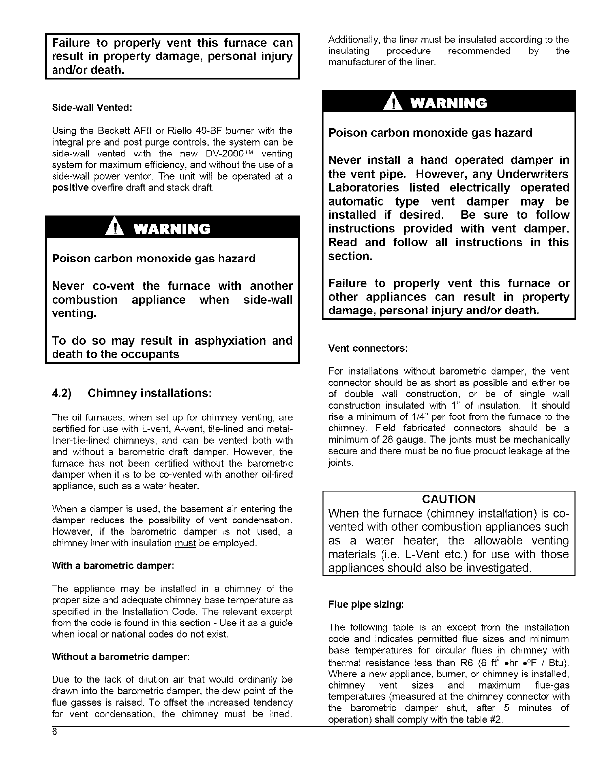
TABLE #1
Minimum Installation clearances from combustible materials (Chimney installation*)
" " NOUF160
Furnace 1"
Sides Supply plenum, warm air duct 1"
within 6 ft of furnace
Back Furnace 18"
Top Furnace casing or plenum 2"
Bottom Furnace - combustible floor 0"
Front Furnace 24"
* See Part 1 section 4.3 for Direct Vent application clearance.
CAUTION
OLR105 -OLF105. NOLF105
• OUF105 - NOUF105
1 "
1 "
1 "
1 "
0"
24"
4) VENTING
4.1) General:
The furnaces can be vented in several ways:
Chimney Vented:
Using the Beckett AFG or Riello 40-F burner, the
furnaces can be chimney vented with or without a
barometric damper. The unit will be operated at a
negative over fire draft and stack draft.
Poison carbon monoxide gas, fire and
explosion hazard.
Read and follow all instructions in this
section.
Page 5
result in property damage, personal injury
I Failure to properly vent this furnace can I
and/or death,
Side-wall Vented:
Additionally, the liner must be insulated according to the
insulating procedure recommended by the
manufacturer of the liner.
I
Using the Beckett AFII or Riello 40-BF burner with the
integral pre and post purge controls, the system can be
side-wall vented with the new DV-2000 TM venting
system for maximum efficiency, and without the use of a
side-wall power ventor. The unit will be operated at a
positive overfire draft and stack draft.
Poison carbon monoxide gas hazard
Never co-vent the furnace with another
combustion appliance when side-wall
venting.
To do so may result in asphyxiation and
death to the occupants
4.2) Chimney installations:
The oil furnaces, when set up for chimney venting, are
certified for use with L-vent, A-vent, tile-lined and metal-
liner-tile-lined chimneys, and can be vented both with
and without a barometric draft damper. However, the
furnace has not been certified without the barometric
damper when it is to be co-vented with another oil-fired
appliance, such as a water heater.
When a damper is used, the basement air entering the
damper reduces the possibility of vent condensation.
However, if the barometric damper is not used, a
chimney liner with insulation must be employed.
With a barometric damper:
Poison carbon monoxide gas hazard
Never install a hand operated damper in
the vent pipe. However, any Underwriters
Laboratories listed electrically operated
automatic type vent damper may be
installed if desired. Be sure to follow
instructions provided with vent damper.
Read and follow all instructions in this
section.
Failure to properly vent this furnace or
other appliances can result in property
damage, personal injury and/or death.
Vent connectors:
For installations without barometric damper, the vent
connector should be as short as possible and either be
of double wall construction, or be of single wall
construction insulated with 1" of insulation, tt should
rise a minimum of 1/4" per foot from the furnace to the
chimney. Field fabricated connectors should be a
minimum of 28 gauge. The joints must be mechanically
secure and there must be no flue product leakage at the
joints.
CAUTION
When the furnace (chimney installation) is co-
vented with other combustion appliances such
as a water heater, the allowable venting
materials (i.e. L-Vent etc.) for use with those
appliances should also be investigated.
The appliance may be installed in a chimney of the
proper size and adequate chimney base temperature as
specified in the Installation Code. The relevant excerpt
from the code is found in this section - Use it as a guide
when local or national codes do not exist.
Without a barometric damper:
Due to the lack of dilution air that would ordinarily be
drawn into the barometric damper, the dew point of the
flue gasses is raised. To offset the increased tendency
for vent condensation, the chimney must be lined.
Flue pipe sizing:
The following table is an except from the installation
code and indicates permitted flue sizes and minimum
base temperatures for circular flues in chimney with
thermal resistance less than R6 (6 ft2 ohr o°F / Btu).
Where a new appliance, burner, or chimney is installed,
chimney vent sizes and maximum flue-gas
temperatures (measured at the chimney connector with
the barometric damper shut, after 5 minutes of
operation) shall comply with the table #2.
Page 6
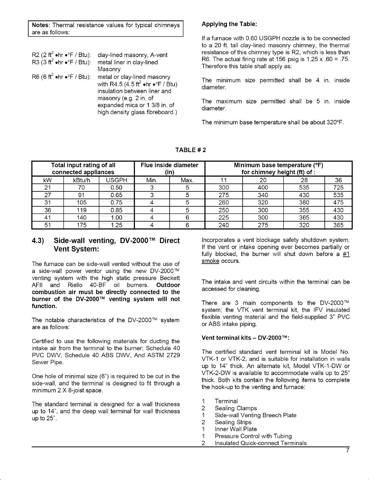
Applying the Table:
J Notes: Thermal resistance values for typical chimneysare as follows:
If a furnace with 0.60 USGPH nozzle is to be connected
to a 20 ft. tall clay-lined masonry chimney, the thermal
R2 (2 ft2 ohro°F / Btu):
R3 (3 ft2 ohro°F / Btu):
R6 (6 ft2 ohro°F / Btu):
Total input rating of all Flue inside diameter Minimum base temperature (°F)
connected appliances (in) for chimney height (if) of :
kW kBtu/h USGPH Min. ' Max. 11 20 28 36
21 70 0.50 3 5 300 400 535 725
27 91 0.65 3 5 275 340 430 535
31 105 0.75 4 5 260 320 380 475
36 119 0.85 4 5 250 300 355 430
41 140 1.00 4 6 225 300 365 430
51 175 1.25 4 6 240 275 320 365
clay-lined masonry, A-vent
metal liner in clay-lined
Masonry
metal or clay-lined masonry
with R4.5 (4.5 ft2 ohro°F / Btu)
insulation between liner and
masonry (e.g. 2 in. of
expanded mica or 1 3/8 in. of
high density glass fibreboard.)
TABLE # 2
resistance of this chimney type is R2, which is less than
R6. The actual firing rate at 156 psig is 1.25 x .60 = .75.
Therefore this table shall apply as:
The minimum size permitted shall be 4 in. inside
diameter.
The maximum size permitted shall be 5 in. inside
diameter.
The minimum base temperature shall be about 320°F.
4.3) Side-wall venting, DV-2000 TM Direct
Vent System:
The furnace can be side-wall vented without the use of
a side-wall power ventor using the new DV-2000 TM
venting system with the high static pressure Beckett
AFtt and Riello 40-BF oil burners. Outdoor
combustion air must be directly connected to the
burner of the DV-2000 TM venting system will not
function.
The notable characteristics of the DV-2000 TM system
are as follows:
Certified to use the following materials for ducting the
intake air from the terminal to the burner; Schedule 40
PVC DWV, Schedule 40 ABS DWV, And ASTM 2729
Sewer Pipe.
One hole of minimal size (6") is required to be cut in the
side-wall, and the terminal is designed to fit through a
minimum 2 X 8-joist space.
The standard terminal is designed for a wall thickness
up to 14", and the deep wall terminal for wall thickness
up to 25".
Incorporates a vent blockage safety shutdown system.
If the vent or intake opening ever becomes partially or
fully blocked, the burner will shut down before a #_!
smoke occurs.
The intake and vent circuits within the terminal can be
accessed for cleaning.
There are 3 main components to the DV-2000 TM
system; the VTK vent terminal kit, the IFV insulated
flexible venting material and the field-supplied 3" PVC
or ABS intake piping.
Vent terminal kits - DV-2000TM:
The certified standard vent terminal kit is Model No.
VTK-1 or VTK-2, and is suitable for installation in walls
up to 14" thick. An alternate kit, Model VTK-1-DW or
VTK-2-DW is available to accommodate walls up to 25"
thick. Both kits contain the following items to complete
the hook-up to the venting and furnace:
1 Terminal
2 Sealing Clamps
1 Side-wall Venting Breech Plate
2 Sealing Strips
1 Inner Wall Plate
1 Pressure Control with Tubing
2 Insulated Quick-connect Terminals
Page 7
3 StainlessSteelScrews
6 Selftappingstainlesssteelscrews
Insulated flexible venting - DV-2000TM:
The certified venting materials come in 3 lengths, Model
No. tFV3-15, IFV3-23 and IFV3-30 (or IFV4-15, IFV4-23
and IFV4-30 for 160 models) are corresponding to 15',
23' and 30' continuous lengths of vent. The vent
construction is coaxial and incorporates a stainless
steel corrugated flexible liner surrounded by a thick
insulation blanket and covered with an outer layer of
flexible corrugated aluminium sleeve to protect the
insulation. Splicing vent lengths together is prohibited.
The maximum and minimum continuous vent lengths
permitted for installation are:
5 feet minimum 30 feet maximum
Poison carbon monoxide gas hazard
c. within 6 feet of a window or door, or mechanical air
supply inlet to any building, including soffit
openings;
d. above a gas meter/regulator assembly within 3 feet
of a vertical centerline of the regulator;
e. within 6 feet of any gas service regulator vent
outlet, or within 3feet of an oil tank vent, or an oil fill
inlet;
f. within less than 1 foot above ground level;
g. 6 feet of any other combustion air inlet;
h. within 6 feet of a property line;
i. underneath a veranda, porch or deck;
j. so that the flue gases are directed at combustible
material or any openings of surrounding buildings
that are within 6 feet;
k. less than 3 feet from an inside corner of an L-
shaped structure;
I. so that the bottom of the vent termination opening is
less than 1 foot above any surface that may support
ice, snow, or debris;
m. so that the flue gases are directed toward
brickwork, siding or other construction, in such a
manner that may cause damage from heat or
condensation from flue gases.
Even though the flexible venting is insulated, it
cannot be run through an unheated space.
To do so could cause residual condensation
inside the stainless steel liner, which may
eventually perforate the liner and allow vent
gasses to enter the dwelling.
TABLE # 3
Side-wall venting clearances to combustibles
PORTION OF VENT ' CLEARANCES
Vent pipe, up to vent terminal* 3"
Vent terminal ZERO
*Do not enclose venting
Installation considerations - DV-2000TM:
Select a location for the vent terminal in accordance
with all local and national codes. The following
requirements shall be considered to be minimum
requirements that can be overridden by stricter local
and national codes.
The vent shall not terminate:
a. directly above a paved sidewalk or paved driveway
that is located between two buildings, and that
serves both buildings;
b. less than 7 feet above any paved driveway;
CAUTION
Most codes have a notwithstanding clause
that states that products of combustion shall
not enter the dwelling under any
circumstances, even if all other code
requirements as to construction and location
have been complied with. The installer is
ultimately responsible to do whatever is
necessary to ensure that flue gasses do not
enter the dwelling.
Installation of side-wall venting - DV-2000TM:
Cuts and abrasion hazard.
Always wear protective gloves and eye
protection when handling the vent material
The process of cutting and fitting the flexible
venting material exposes the installer to sharp
edges that could cause severe cuts to the
skin.
Page 8
FIGURE # 1.1
FIGURE # 1.2
SL
EAD SPIN SLEEVE
NTO OUTER SLEEV
FIGURE # 1.3 FIGURE # 1.4
FIGURE # 1.5 FIGURE # 1.6
Page 9
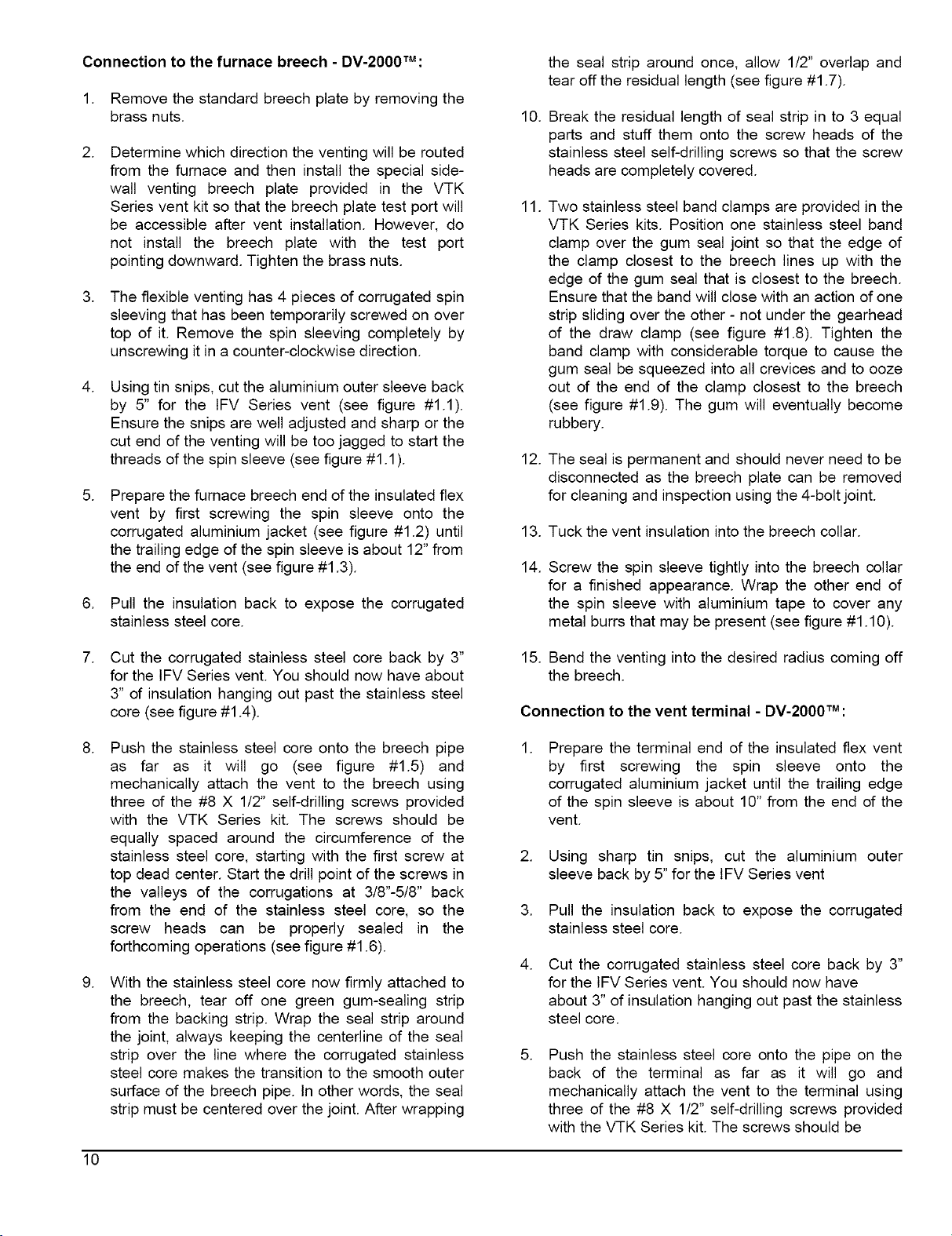
Connection to the furnace breech - DV-2000TM:
1. Remove the standard breech plate by removing the
brass nuts.
.
Determine which direction the venting will be routed
from the furnace and then install the special side-
wall venting breech plate provided in the VTK
Series vent kit so that the breech plate test port will
be accessible after vent installation. However, do
not install the breech plate with the test port
pointing downward. Tighten the brass nuts.
.
The flexible venting has 4 pieces of corrugated spin
sleeving that has been temporarily screwed on over
top of it. Remove the spin sleeving completely by
unscrewing it in a counter-clockwise direction.
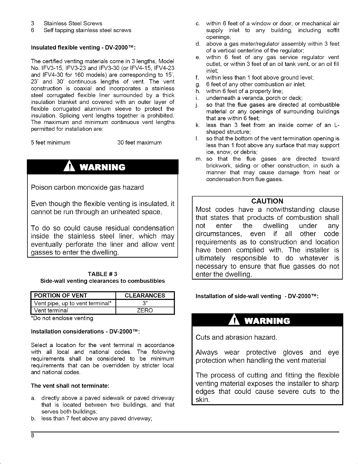
.
Using tin snips, cut the aluminium outer sleeve back
by 5" for the IFV Series vent (see figure #1.1).
Ensure the snips are well adjusted and sharp or the
cut end of the venting will be too jagged to start the
threads of the spin sleeve (see figure #1.1 ).
.
Prepare the furnace breech end of the insulated flex
vent by first screwing the spin sleeve onto the
corrugated aluminium jacket (see figure #1.2) until
the trailing edge of the spin sleeve is about 12" from
the end of the vent (see figure #1.3).
6. Pull the insulation back to expose the corrugated
stainless steel core.
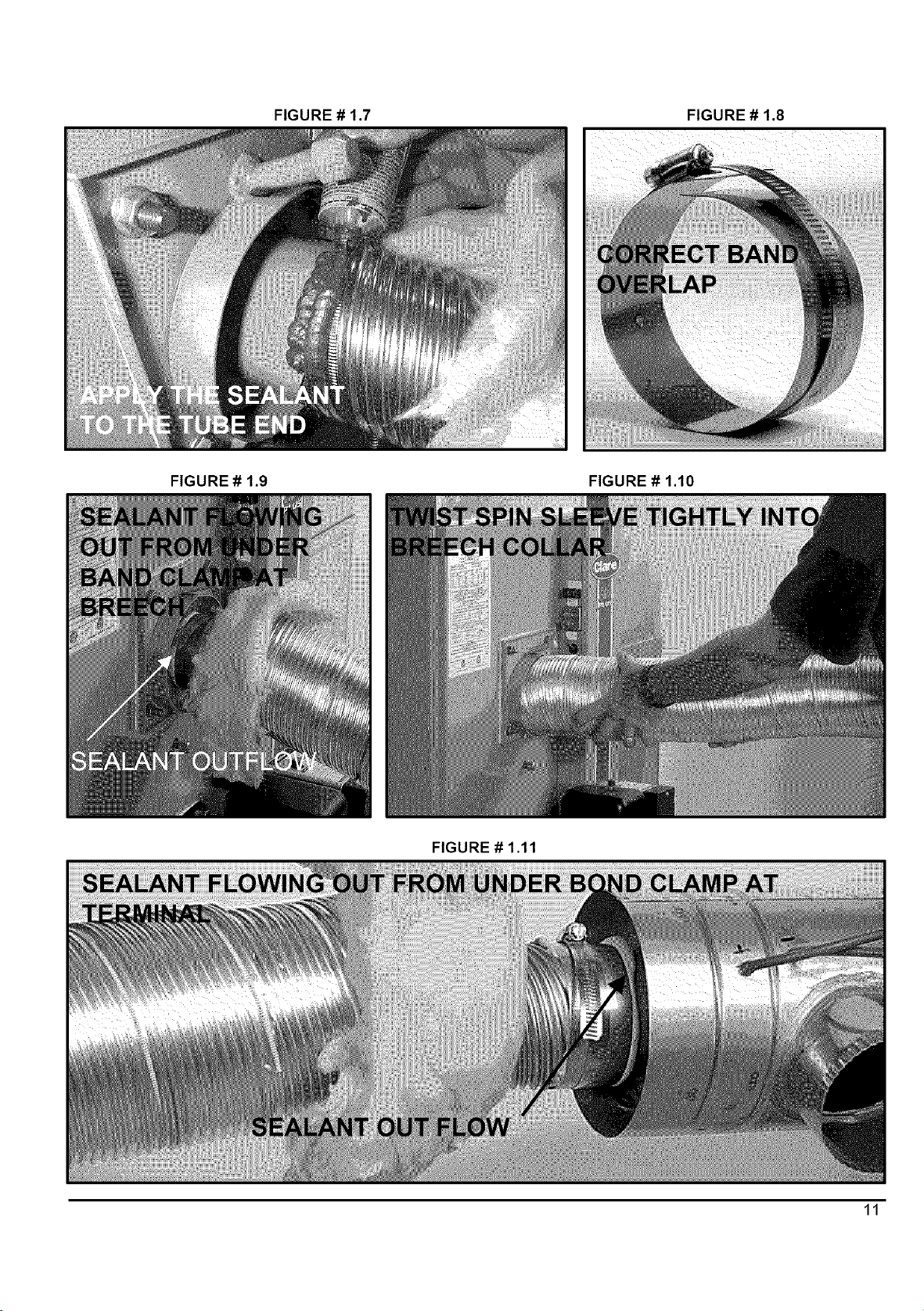
the seal strip around once, allow 1/2" overlap and
tear off the residual length (see figure #1.7).
10.
Break the residual length of seal strip in to 3 equal
parts and stuff them onto the screw heads of the
stainless steel self-drilling screws so that the screw
heads are completely covered.
11.
Two stainless steel band clamps are provided in the
VTK Series kits. Position one stainless steel band
clamp over the gum seal joint so that the edge of
the clamp closest to the breech lines up with the
edge of the gum seal that is closest to the breech.
Ensure that the band will close with an action of one
strip sliding over the other - not under the gearhead
of the draw clamp (see figure #1.8). Tighten the
band clamp with considerable torque to cause the
gum seal be squeezed into all crevices and to ooze
out of the end of the clamp closest to the breech
(see figure #1.9). The gum will eventually become
rubbery.
12. The seal is permanent and should never need to be
disconnected as the breech plate can be removed
for cleaning and inspection using the 4-bolt joint.
13. Tuck the vent insulation into the breech collar.
14.
Screw the spin sleeve tightly into the breech collar
for a finished appearance. Wrap the other end of
the spin sleeve with aluminium tape to cover any
metal burrs that may be present (see figure #1.10).
.
Cut the corrugated stainless steel core back by 3"
for the IFV Series vent. You should now have about
3" of insulation hanging out past the stainless steel
core (see figure #1.4).
.
Push the stainless steel core onto the breech pipe
as far as it will go (see figure #1.5) and
mechanically attach the vent to the breech using
three of the #8 X 1/2" self-drilling screws provided
with the VTK Series kit. The screws should be
equally spaced around the circumference of the
stainless steel core, starting with the first screw at
top dead center. Start the drill point of the screws in
the valleys of the corrugations at 3/8"-5/8" back
from the end of the stainless steel core, so the
screw heads can be properly sealed in the
forthcoming operations (see figure #1.6).
.
With the stainless steel core now firmly attached to
the breech, tear off one green gum-sealing strip
from the backing strip. Wrap the seal strip around
the joint, always keeping the centerline of the seal
strip over the line where the corrugated stainless
steel core makes the transition to the smooth outer
surface of the breech pipe. In other words, the seal
strip must be centered over the joint. After wrapping
15. Bend the venting into the desired radius coming off
the breech.
Connection to the vent terminal - DV-2000TM:
Prepare the terminal end of the insulated flex vent
by first screwing the spin sleeve onto the
corrugated aluminium jacket until the trailing edge
of the spin sleeve is about 10" from the end of the
vent.
2. Using sharp tin snips, cut the aluminium outer
sleeve back by 5"for the IFV Series vent
3. Pull the insulation back to expose the corrugated
stainless steel core.
.
Cut the corrugated stainless steel core back by 3"
for the IFV Series vent. You should now have
about 3" of insulation hanging out past the stainless
steel core.
Push the stainless steel core onto the pipe on the
back of the terminal as far as it will go and
mechanically attach the vent to the terminal using
three of the #8 X 1/2" self-drilling screws provided
with the VTK Series kit. The screws should be
10
Page 10
FIGURE# 1.7 FIGURE # 1.8
FIGURE # 1.9 FIGURE # 1.10
FIGURE # 1.11
11
Page 11
equallyspacedaroundthe circumferenceof the
stainlesssteelcore,startingwiththefirstscrewat
topdeadcenter.Startthedrillpointofthescrewsin
thevalleysof thecorrugationsat 3/8"-5/8"back
fromtheendofthestainlesssteelcore.
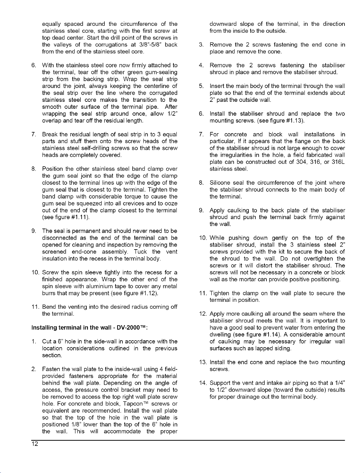
downward slope of the terminal, in the direction
from the inside to the outside.
Remove the 2 screws fastening the end cone in
place and remove the cone.
.
With the stainless steel core now firmly attached to
the terminal, tear off the other green gum-sealing
strip from the backing strip. Wrap the seal strip
around the joint, always keeping the centerline of
the seal strip over the line where the corrugated
stainless steel core makes the transition to the
smooth outer surface of the terminal pipe. After
wrapping the seal strip around once, allow 1/2"
overlap and tear off the residual length.
.
Break the residual length of seal strip in to 3 equal
parts and stuff them onto the screw heads of the
stainless steel self-drilling screws so that the screw
heads are completely covered.
.
Position the other stainless steel band clamp over
the gum seal joint so that the edge of the clamp
closest to the terminal lines up with the edge of the
gum seal that is closest to the terminal. Tighten the
band clamp with considerable torque to cause the
gum seal be squeezed into all crevices and to ooze
out of the end of the clamp closest to the terminal
(see figure #1.11 ).
.
The seal is permanent and should never need to be
disconnected as the end of the terminal can be
opened for cleaning and inspection by removing the
screened end-cone assembly. Tuck the vent
insulation into the recess in the terminal body.
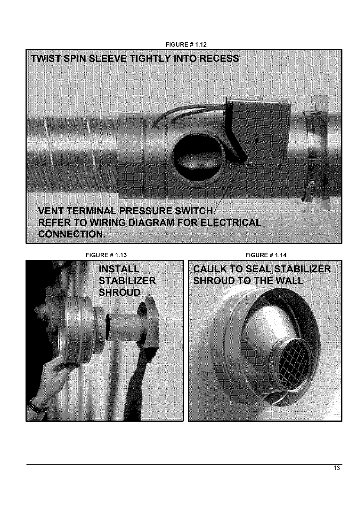
10. Screw the spin sleeve tightly into the recess for a
finished appearance. Wrap the other end of the
spin sleeve with aluminium tape to cover any metal
burrs that may be present (see figure #1.12).
11. Bend the venting into the desired radius coming off
the terminal.
Installing terminal in the wall - DV-2000TM:
1. Cut a 6" hole in the side-wall in accordance with the
location considerations outlined in the previous
section.
.
Fasten the wall plate to the inside-wall using 4 field-
provided fasteners appropriate for the material
behind the wall plate. Depending on the angle of
access, the pressure control bracket may need to
be removed to access the top right wall plate screw
hole. For concrete and block, Tapcon TM screws or
equivalent are recommended. Install the wall plate
so that the top of the hole in the wall plate is
positioned 1/8" lower than the top of the 6" hole in
the wall. This will accommodate the proper
.
Remove the 2 screws fastening the stabiliser
shroud in place and remove the stabiliser shroud.
Insert the main body of the terminal through the wall
plate so that the end of the terminal extends about
2" past the outside wall.
.
Install the stabiliser shroud and replace the two
mounting screws. (see figure #1.13).
For concrete and block wall installations in
particular, If it appears that the flange on the back
of the stabiliser shroud is not large enough to cover
the irregularities in the hole, a field fabricated wall
plate can be constructed out of 304, 316, or 316L
stainless steel.
Silicone seal the circumference of the joint where
the stabiliser shroud connects to the main body of
the terminal.
.
Apply caulking to the back plate of the stabiliser
shroud and push the terminal back firmly against
the wall.
10.
While pushing down gently on the top of the
stabiliser shroud, install the 3 stainless steel 2"
screws provided with the kit to secure the back of
the shroud to the wall. Do not overtighten the
screws or it will distort the stabiliser shroud. The
screws will not be necessary in a concrete or block
wall as the mortar can provide positive positioning.
11.
Tighten the clamp on the wall plate to secure the
terminal in position.
12.
Apply more caulking all around the seam where the
stabiliser shroud meets the wall. It is important to
have a good seal to prevent water from entering the
dwelling (see figure #1.14). A considerable amount
of caulking may be necessary for irregular wall
surfaces such as lapped siding.
13.
Install the end cone and replace the two mounting
screws.
14.
Support the vent and intake air piping so that a 1/4"
to 1/2" downward slope (toward the outside) results
for proper drainage out the terminal body.
12
Page 12
FIGURE# 1.12
FIGURE # 1.13 FIGURE # 1.14
13
Page 13
Connectionofcombustionairpipingto theterminal
. DV.2000TM:
Refer to Part 1, section 5.3, Outdoor Combustion Air -
Side-wall Venting, DV-2000 TM for a complete
description.
5) AIR FOR COMBUSTION
Poison carbon monoxide gas hazard.
Comply with NFPA standard for the
installation of Oil Burning Equipment and
applicable provision of local building
codes to provide combustion and
ventilation air.
Failure to provide adequate combustion
and ventilation air can result in personal
injury and/or death.
The following areas or types of structures may contain
or have exposure to the substances listed below. The
installation must be evaluated carefully as it may be
necessary to provide outside air for combustion.
a. Commercial building.
b. Building with indoor pools.
c. Furnaces installed near chemical storage areas.
Exposure to these substances:
a. Permanent wave solutions for hair.
b. Chlorinated waxes and cleaners.
c. Chlorine based swimming pool chemicals.
d. Water softening chemicals.
e. De-icing salts or chemicals.
f. Carbon tetrachloride.
g. Halogen type refrigerants.
h. Cleaning solvent (such as perchloroethylene).
i. Printing inks, paint removers, varnishes, etc..
j. Hydrochloric acid.
k. Solvent cements and glues.
I. Antistatic fabric softeners for clothes dryers.
m. Masonery acid washing materials.
5.3) Ducted outdoor combustion air:
5.1) General:
Oil furnaces must have an adequate supply of
combustion air. It is common practice to assume that
older homes have sufficient infiltration to accommodate
the combustion air requirement for the furnace.
However, home improvements such as new windows,
doors, and weather stripping have dramatically reduced
the volume of air leakage into the home.
Home air exhausters are common. Bath and kitchen
fans, power vented clothes dryers, and water heaters all
tend to create a negative pressure in the home. Should
this occur, the chimney becomes less and less effective
and can easily downdraft.
Heat recovery ventilation (HRV) systems are gaining in
popularity. The HRVs are not designed to supply
combustion air. tf not properly balanced, a serious
negative pressure condition could develop in the
dwelling.
5.2) Contaminated Combustion Air :
Installation in certain areas or types of structures will
increase the exposure to chemicals or Halogens which
may harm the furnace. These instances will require that
only outside air for combustion.
Three burners are set up to duct outside combustion air
directly to the burner; the Beckett AFII and Riello 40-BF
for side-wall venting using the new DV-2000 TM venting
system, and the Beckett AFG for use with conventional
chimney venting. The Riello 40-F is not suitable for
direct-connected outdoor air.
CAUTION
The use of ducted outside combustion air is
mandatory for the DV-2000 TM venting system.
This system operates on a balanced flue
principle and will not function properly if the
combustion air piping is not attached and
sealed at all connections between the vent
terminal and burner inlet.
Outdoor combustion air kit - chimney venting:
The following kit has been certified for use on the
appliance. The component kits contain an important
safety feature, namely a vacuum relief valve, or VRV.
During normal operation the burner aspirates outdoor
air. If the intake terminal ever becomes partially blocked
or fully blocked from ice or snow etc., the VRV will open
to allow a proportion of air from the dwelling to enter the
burner thus maintaining proper combustion. Once the
blockage is removed, the VRV will close and the burner
will draw all air from the outdoors again:
14
Page 14

CAS-2B Components(exceptair duct)forthe
BeckettAFG burner.The kit includesthe intake
terminal,vacuumreliefvalve(VRV)andspecialairboot
connectionwithintegralairadjustmentmeansforthe
AFG burner.The CAS-2Bcan be usedwith 4"
galvanisedairductorwith4"flexiblealuminiumairduct.
Itisrecommendedthatthemetallicairductingmaterial
shouldbeinsulatedfromtheairintakeupto5 feetfrom
theburnertoavoidcondensationontheoutsideofthe
intakepipe.
CAD-1Air duct kit consistsof 25 feet of insulated
UL/ULCListedClass1 airduct,andtwo4"steelband
clamps. The ductincorporatesa corrugatedflexible
aluminiumcore, surroundedby fibreglassinsulation
coveredwithavinylvapourbarrier.
CAUTION
The CAS-2B does not turn the furnace
installation into a direct vent system.
Therefore the building structure must provide
for adequate combustion air to be delivered at
the vacuum relief valve. The burner will
need to draw combustion air from the VRV's
surroundings if the intake ever becomes
blocked. Therefore non-direct vent installation
codes must be followed.
Comprehensive installation instructions are provided
with the kit.
Outdoor combustion air - side-wall venting, DV-
2000 TM:
The new DV-2000 TM venting system is a sealed system
and completely isolates the furnace from the interior of
the building. The burner is totally unaffected by any
pressure fluctuations within the building which makes it
ideal for tight home constructions.
The DV-2000 TM venting system requires additional
parts, which are not included with the kit. These
additional parts must be constructed of 3" Schedule 40
PVC, PVC-SWV, SDR-26,SDR-21, Septic Sewer Pipe,
or ABS plastic pipe, fittings and sealant. Also,
installation procedures, piping and fittings must conform
to the following ANSI/ASTM standards:
Procedure for
Cementing Joints
Additional parts required (not included in VTK kit):
a. 3" elbow fitting as required
b. 3" plastic pipe
c. 3" 90°elbow, female-female(for terminal)
d. 3" female to 2" female reducer (Riello 40-BF burner
only)
e. 2" 90°elbow, street type, female-male (Riello 40-BF
burner only)
f. 3" female-female PVC or ABS coupling (not sewer
pipe) (Beckett AFII burner only)
g. transition bushings to go from PVC or ABS to
ASTM D2729 Septic Sewer Pipe (if applicable).
If PVC fittings are mixed with ABS fittings, use a solvent
cement that is approved for bonding the two plastics.
Intake pipe length - DV-2000TM:
The DV-2000 TMventing system has been certified for
120 equivalent feet of 3" intake pipe. Count a 90°elbow
as 10 equivalent feet and a 45°elbow as 5 equivalent
feet in the calculation.
For Example:
1
2
3
2
1
1
Intake pipe installation - DV-2000TM:
Obtain the necessary additional parts, to complete the
installation, and start by piping at the burner, tf the
optional vestibule has been installed, remove the
appropriate knockouts in the side panels of the
vestibule. The lower 5" knockout in the right hand panel
is used for the Beckett AFIt burner. The higher 5"
knockouts on the right and left-hand panels are for right
or left connection to the Riello 40-BF burner.
Beckett AFII burner:
5' Length = 5 equivalent feet
10' Lengths = 20 equivalent feet
90°elbows = 30 equivalent feet
45°elbows = 10 equivalent feet
90°elbow (terminal) = 10 equivalent feet
90°elbow (Riello Burner) = 10 equivalent feet
Total = 85 equivalent feet,
which is less than 120 feet,
which is acceptable.
ASTM D-2855
PVC
SDR26, SDR21
Septic Sewer Pipe
PVC-DWV
PVC Primer and
Solvent Cement
ABS Pipe and Fittings
ASTM D- 1785
ASTM D-2241
ASTM D-2729
ASTM D-2665
ASTM D-2564
ASTM D-2235
Remove the burner intake cover by removing the 3
screws securing it in place. Discard the cover and
screws. Apply silicone liberally around the end of a 3"
coupling and fully insert the silicone end onto the burner
opening. Fasten securely with 3 self-tapping sheet
metal screws.
15
Page 15

Riello 40-BF burner:
7) BURNER INSTALLATION
Fully insert the female end of the 2" 90° street elbow
into the combustion air fitting on top of the burner.
Fasten securely with 3 self-tapping sheet metal screws.
Cement the 2" end of the 3" female to 2" female reducer
onto the male end of the 2" 90° street elbow, tf these
parts are not easily obtained, use a 3" 90° street elbow
with the male end fitted over the combustion air fitting.
The fitting will have to be silicone sealed as the fit is a
bit loose. Fasten securely with 3 self-tapping sheet
metal screws.
Terminal connection:
Insert the 3" 90° female-female elbow onto the stainless
steel air intake fitting located on the right side of the
vent terminal (viewing from the rear). Fasten securely
with 3 self-tapping sheet metal screws.
Intermediate piping:
Pipe as required between the terminal and the burner.
Ensure that the 3" piping is routed and supported in
accordance with local and national codes. Obey
minimum furnace clearances to combustibles when
routing any sections of 3" piping in the vicinity of the
furnace, tf Septic Sewer Pipe is to be used, install
transition bushings at the 3" female ends of the fittings
at the burner and at the terminal. Transition bushings
are readily available and are required because 3" PVC
and ABS pipes have a typical outside diameter of 3.5",
whereas Septic Sewer Pipe has a typical outside
diameter of 3.25".
6) OIL TANKS AND LINES
Check your local codes for the installation of the tank
and accessories.
A manual shut-off valve and an oil filter shall follow
sequence from tank to burner. Be sure that the oil line
is clean before connecting to the burner. The oil line
should be protected to eliminate any possible damage.
Installations having the fuel oil tank below the burner
level must employ a two pipe fuel supply system with an
appropriate fuel pump (more than 8' lift use 2 stage
pump and more than 16' an auxiliary pump).
Follow the pump instructions to determine the size of
tubing you need in relation of the lift, or the horizontal
distance.
Mounting the burner:
a.
The warm air furnace burner mounting plate has a
four bolts configuration.
b.
Position the mounting gasket between the mounting
flange and the appliance burner mounting plate.
Line up the holes in the mounting flange with the
studs on the appliance mounting plate and securely
bolt in place.
After the burner is mounted:
a. Remove drawer assembly or air tube combination
b. Install nozzle (see specifications)
c. Confirm electrode settings
d. Make the electrical connections
e. Complete oil line connections
CAUTION
Do not turn on the burner until you have
checked the polarity
Checking the polarity:
The oil burners used on the furnaces have solid state
control systems which makes them sensitive to the
proper connections of the hot and neutral power lines.
The controls will be damaged if the two lines are
reversed.
a. Set your voltmeter to line voltage.
b. Place one prong on your grounded electric entry
box and one prong on the black wire.
c. Read the voltage.
d. If the voltage is zero, check the white wire. If line
voltage shows. Reverse the 115-volt leads entering
the furnace junction box.
FIGURE # 2
BLACK
V
16
cA
BLACK
RED
Page 16

Nozzles:
The burners are provided with the highest capacity
USGPH nozzle installed. If another size nozzle, or
replacement nozzle is required, use the nozzle spray
angle, type and manufacturer recommended in Table
#4.1 to 4.3. Note that all nozzle-marked sizes are
based on a pump pressure of 100 psi.
Always select nozzle sizes by working back from the
actual desired flow rate at operating pressure, and not
by the nozzle marking.
NOTE: You may notice a slight odor the first time your
furnace is operated. This will soon disappear. It is only
the oil used on the parts during manufacturing.
8) INSTALLING ACCESSORIES
Electrical shock hazard.
Air and turbulator settings:
Before starting the burner for the first time, adjust the air
and turbulator settings to those listed in the Table #4.1
to #4.3. Once the burner becomes operational, final
adjustment will be necessary.
Fuel supply system:
Fuel Specifications
I NOTE: Use No.1 or No.2 Heating Oil (ASTM D396) or
in Canada, use No.1 or No.2 Furnace Oil.
Before starting the burner be sure the fuel tank is
adequately filled with clean oil.
Fire and explosion hazard.
Turn OFF electric power at fuse box or
service panel before making any electrical
connections and ensure a proper ground
connection is made before connecting line
voltage.
Failure to do so could result in property
damage, bodily injury or death.
8.1) Electronic air cleaner:
Wire leads are provided to direct 115 volts @ 0.5 Amp
maximum to an electronic air cleaner (EAC). Power will
be available to the EAC at all times, so it must
incorporate a flow proving switch if it is to be wired into
the furnace control box. Most modern EACs have the
required integral airflow-proving switch. Wire the
electronic air cleaner as indicated in figure #6.
8.2) Humidifier:
Use only approved heating type oil in this
furnace. DO NOT USE waste oil, used
motor oil, gasoline or kerosene.
Use of these will result in death, personal
injury and/or property damage.
IMPORTANT
When using nozzle sizes of less than .75
USGPH, the Installation Code for oil burning
equipment requires the installation of a 10
micron (or less) filter in the fuel oil line. ICP
requires that this practice be followed in order
to keep the lifetime heat exchanger warranty
intact.
Terminals are provided to direct 115 volts @ 1.0 Amp
maximum to the transformer powering the humidifier.
The humidifier will be energised anytime the blower is
operating on the "Heating Speed". Wire the 115-volt
power as indicated in figure #6.
8.3) Air conditioning:
An air conditioning coil may be installed on the
airside only. Also, notwithstanding the evaporator coil
manufacturer's instructions, a minimum of 6 inches
clearance must be allowed between the bottom of the
coil drain pan, and the top of the heat exchanger. Wire
the thermostat and condensing unit contactor as
indicated in figure #6.
17
Page 17

8.4) Ductwork and Filter:
Installation:
Design and install air distribution system to comply with
Air Conditioning Contractors of America manuals or
other approved methods that conform to local codes
and good trade practices.
When furnace supply ducts carry air outside furnace
area, seal return air duct to furnace casing and
terminate duct outside furnace space.
Install air conditioning cooling coil (evaporator) on
downstream side (in the supply air plenum) or furnace.
If separate evaporator and blower unit is used, install
good sealing dampers for air flow control. Cold air from
the evaporator coil going through the furnace could
cause condensation and shorten furnace life.
Dampers (purchased locally) MUST be
I CAUTION
automatic.
Poison carbon monoxide gas hazard.
Do NOT draw return air from inside a
closet or utility room. Return air duct
MUST be sealed to furnace casing.
Failure to properly seal duct can result in
death, personal injury and/or property
damage.
Poison carbon monoxide gas hazard.
Install evaporator coil on the supply side of
the furnace ducting.
Evaporator coil installed in return side
ducting can cause condensation to form
inside heat exchanger resulting in heat
exchanger failure. This could result in
death, personal injury and/or property
damage.
18
Page 18

PART 2
OPERATION
_ii_i;i_i3i_ii_ii_ii_ii_i_ii_ii_ii_ii_ii_ii_ii_ii_ii_ii_ii_ii_ii_ii_ii_ii_ii_ii_ii_ii_ii_ii_ii_ii_ii_ii_ii_ii_ii_ii_ii_ii_ii_ii_ii_ii_ii_ii_ii_ii_ii_ii_ii_iiiii_iii!iii!_!i_ii_i_i_i_ii_i_:i_`i_`i_:!_iiiiii_i_i_ii_ii_i_ii_
1)
MANUAL OPERATION SWITCHES 7. After fan-limit control heats up to the factory set
point, the circulating air blower starts.
FIGURE # 3 8. The circulating air blower, burner motor and ignition
transformer remains on until the thermostat is
satisfied. Also, the solenoid valve remains open.
9. Thermostat is satisfied.
blower
operation switch
(low speed)
power ON-
10. SPDT relay contacts open, solenoid valve closes,
burner fan motor post-purges the combustion
chamber and vent for a pre-set time (30 sec. to 4
min.). The ignition transformer also continues to
spark for this time period.
11. During the post-purge cycle, the fan-limit control
cools down to the factory set point of 90 degrees
Fahrenheit, and the circulating air blower turns off.
OFF switch
2.2) Sequence of operation - Riello 40-
BF, Side-wall Venting:
1. Normally open contact (W-R) on SPDT relay closed
when thermostat calls for heat.
DNS-0574 Rev. B
2)
2.1)
SEQUENCE OF OPERATION
Sequence of operation - Beckett
AFII, Side-wall venting:
For the Beckett AFII burner, the T-T terminal have
to be jumped on the primary control of the burner.
.
Normally open contact (W-R) on SPDT relay closed
when thermostat calls for heat.
.
Burner motor starts and spark is established. The
burner motor fan pre-purges the combustion
chamber and vent for 15 or 20 seconds,
establishing the combustion air pattern.
.
After prepurge period, solenoid valve opens
allowing oil to flow through nozzle.
.
The ignition transformer spark ignites oil spray.
6.
Cad cell senses flame and burner continues to fire.
.
Burner motor starts. The burner motor fan pre-
purges the combustion chamber and vents for 10
seconds, establishing the combustion air pattern.
During this time the solenoid valve holding coil
pressure will be approximately 100 psig.
After prepurge period, solenoid valve opens,
allowing oil to flow through nozzle. At the same
time, the burner motor's ignition coil produces
spark.
4. The ignition transformer spark ignites oil spray.
5. Cad cell senses flame and burner continues to fire.
Ignition transformer ceases sparking.
6. After fan-limit control heats up to the factory set
point, the circulating air blower starts.
7. The circulating air blower and burner motor remain
on until the thermostat is satisfied. Also, the
solenoid valve remains open.
8. Thermostat is satisfied.
.
Relay contacts open, solenoid valve closes, and
then the burner fan motor post-purges the
combustion chamber and vent for a pre-set time (5"
breech model only) (0 min. to 6 min.).
19
Page 19

10.Duringthepost-purgecycle,thefan-limitcontrolBI-
metalcoolsdownto the factoryset pointof 90
degreesFahrenheit,andthecirculatingairblower
turnsoff.
2.4) Sequence of operation - internal
furnace controls (All models) :
No call for heating or cooling:
BF will post-purge when 115 volt power is applied to the
I NOTE: With burner relay contact open, the Riello 40-
burner.
2.3) Sequence of operation - Beckett
AFG and Riello 40-F, chimney:
1. For the AFG burner, the T-T terminal have to be
jumped on the primary control of the burner.
2. Normally open contact (W-R) on SPDT relay closed
when thermostat calls for heat.
.
AFG Burner: The motor starts and spark is
established. The pump pressure builds and the
poppet valve opens admitting fuel to the nozzle.
Pressure builds and poppet valve opens, allowing
oil to flow through nozzle.
40F: Burner motor starts. The burner motor fan
pre-purges the combustion chamber and vent for
10 seconds, establishing the combustion air
pattern. During this time the solenoid valve holding
coil pressure will be approximately 100 psig.
Solenoid valve opens, allowing oil to flow through
nozzle. At the same time, the burner motor's
ignition coil produces spark.
Power is available to the Electronic Air Cleaner (EAC)
at all times. Power at L1 enters the common terminal of
the single pole double throw (SPDT) relay, and then
passes through the normally closed (NC) switch of the
relay and continues to the normally closed (NC) switch
of the fan control. This provides power to the constant
blower operation speed tap on the blower motor if the
constant (low speed) blower operation switch is
selected to be close. The low speed motor tap would
normally be chosen for constant blower operation.
Call for heat:
Power comes from L1 to the limit control and then
leaves the limit control via the red wire to provide power
to the burner. RH W close in the thermostat
completing a 24 volt circuit the SPDT relay coil. This
relay energises and switches 115 volts power to
operate the oil burner.
When the plenum temperature reaches the fan "On"
setting, the normally open (NO) fan control contacts
close and the normally closed (NC) contacts open.
Power then flows to the heating speed tap selected on
the blower motor, and to the HUM power lead to supply
115 volts to the humidifier transformer.
Call for cooling:
4. Spark ignites oil droplets.
5. Cad cell senses flame and burner continues to fire.
Ignition transformer ceases sparking (Riello R40-F).
6. After fan-limit control heats up to the factory set
point, the circulating air blower starts.
.
The circulating air blower and burner motor remain
on until the thermostat is satisfied (AFG). The
ignition transformer continues to spark (AFG). The
solenoid valve remains open (R40-F).
8. Thermostat is satisfied.
9. SPDT relay contacts open, solenoid valve closes
(R40-F), burner fan motor shuts down. The ignition
transformer ceases sparking (AFG).
10. The fan-limit control Bl-metal cools down to the
factory set point of 90 degrees Fahrenheit, and the
circulating air blower turns off.
2O
Rc - G close in the thermostat completing a 24-volt
circuit to the SPDT relay coil. The NC contacts open
interrupting power to the fan control. The NO contacts
close and power flows to the cooling speed tap
selected.
Rc - Y also close in the thermostat completing a 24-volt
circuit to the outdoor condensing unit contactor coil. The
contactor closes and switches power to the compressor
and condenser fan in the condensing unit.
2.5) Sequence of operation - DV-2000 TM
Venting system:
Normal operation:
1. Before a call for heat the contacts of the pressure
switch are closed.
. When the room thermostat calls for heat the
normally open contact W-R close and the burner
blower starts and creates suction in the intake
piping circuit and a pressure in the vent piping
circuit.
Page 20

3. Thedifferentialpressuresetpointof the pressure
switchis notexceededandthe thermostatcircuit
remainscloseduntilthecallforheathasended.
Abnormal operation:
should flow absolutely free of white streaks or bubbles
to indicate that no air is being drawn into the suction
side of the oil piping and pump. Tighten the bleed screw
and the burner will fire. Adjust the oil pressure as
indicated in Table #4.1 to #4.3.
Start-up:
When the room thermostat calls for heat the
normally open contact W-R close and the burner
blower starts and creates suction in the intake
piping circuit and a pressure in the vent piping
circuit.
.
If there is a blockage in the intake or vent openings
to cause a pressure differential beyond the set point
of the pressure switch, then the thermostat circuit is
opened and the burner will go into a 2 minute post-
purge and then shut down.
.
After the post-purge, once the burner blower shuts
down, the pressure switch contacts will re-close. If
the call for heat remains, the burner will re-start. If
the blockage still exists, the thermostat is again
opened, and the burner post- purges again. The
post-purge function thus becomes an inherent anti-
short cycling device.
.
The unit will essentially go into a continuous re-
cycling post-purge mode with no heat being
supplied to the dwelling, which will prompt a call for
service to the equipment.
IMPORTANT
The burner must be put in operation for at
least 10 minutes before any test readings are
taken. For new installations, set up the burner
to the settings (see table #4.1 to 4.3), before
firing. These are rough adjustments but they
will ensure that the burner will start and run
smoke-free in advance of the fine adjustments
being made.
3.2) Restart if Burner Should Stop:
1. Set thermostat lower than the room temperature.
2. Press the reset button on the burner primary control
(relay).
3. Set thermostat higher than the room temperature
for 10 seconds and set lower than room
temperature. This will start pre purge cycle.
Repeat twice.
4. Set thermostat higher than the room temperature.
5. During the re-cycling post-purges, if the blockage of
the terminal is removed, the burner will immediately
fire up at the end of the current post purge cycle.
During operation:
If the terminal vent or intake openings become blocked
to the point where the set point of the pressure switch is
exceeded, during a firing cycle, the burner flame will
shut down and the burner will go into the indefinite
recycling post-purge mode as described above, until the
blockage is removed.
3) CHECKS AND ADJUSTMENTS
3.1) General:
During initial start-up and subsequent yearly
maintenance calls, the furnace must be thoroughly
tested.
Open the oil bleed port screw and start the burner.
Allow the oil to flush into a portable container for at least
10 seconds. Slowly close the bleed screw - the oil
5. If the burner motor does not start or ignition fails,
turn off the disconnect switch and CALL YOUR
SERVICEMAN
CAUTION
Do not attempt to start the burner when
excess oil has accumulated, when the furnace
is full of vapour, or when the combustion
chamber is very hot.
Always keep the supply valve shut off if the
burner is shut down for an extended period of
time.
3.3) Combustion chamber curing:
Some moisture and binders remain in the ceramic
combustion chambers after fabrication. It is important to
clear the chamber of these residues before testing. If
you smoke test before curing, the instrument may
become damaged. To cure the chamber, run the unit for
3 consecutive cycles, with 3 minutes of elapsed time in
between each cycle. Each burn cycle should be 3
21
Page 21

minutesduration.Theexhaustwillhavea pungentodor
andproduceawhitecloudofsteam.
3.4) Perform the smoke / CO2 test:
fan speed, investigate for ductwork restriction(s),
dirty or improper air filter, or overfiring caused by
excessive pump pressure, or inproper nozzle
sizing.
For chimney installations, pierce a test hole in the
smoke pipe near the furnace breech. For side-wall
vented installations, remove the threaded cap from
the extended test pipe that is welded into 4-bolt
breech plate. Insert the smoke test instrument
probe into the open hole.
2. Starting with a zero smoke reading, gradually
reduce the burner air setting until just a trace (#1 on
Bacharach Scale) of smoke results.
3. Take a CO2 sample at the same test location
where the smoke sample was taken. Note the CO2
reading associated with the #1 smoke condition.
4. For chimney vented installations, adjust the burner
air setting to obtain a CO2 reading 1% lower than
the reading associated with the #1 smoke.
5. For side-wall vented installations, adjust the burner
air setting to obtain a CO2 reading 1.5% lower than
the reading associated with the #1 smoke.
This method of adjusting the CO2 will allow
adequate excess air to ensure that the burner will
burn clean for the entire heating season, and will
ensure proper calibration of the DV-2000 TM blocked
intake/ vent safety shutdown system used in side-
wall venting applications.
3.5) Perform the supply air temperature
rise test:
1. Operate the burner for at least 10 minutes.
2. Measure the temperature of the air in the return air
plenum.
3.6) Fan limit adjustment:
FIGURE # 4
DNS-0355 Rev.B
1 Limit"FAN OFF" I 90OF
2 Limit"FAN ON"
Model : OLR160 110°F
Model : OUF105, OLF105, OLR105, 130UF
OUF160, NOUF105, NOLF105 &
NOUF160
3 Limit "HI"
Model: OLR160 170UF
Model: OUF105, OLF105, OLR105, 180OF
NOUF105 & NOLF105
Model: OUF160 & NOUF160 220UF
.
Measure the temperature of the air in the largest
trunk coming off the supply air plenum, just "out of
the line of sight" of the radiation coming off the heat
exchanger; 12" away from the plenum on the main
take-off usually satisfies this objective.
4. The temperature rise is calculated by subtracting
the return air temperature from the supply air
temperature.
.
If the temperature rise exceeds the temperature
specified in table #4.1 to #4.3, change to the next
higher blower speed tap until the temperature rise
falls to at this temperature or below. If the excessive
temperature rise cannot be reduced by increasing
22
3.7) Vent temperature test:
1. Place a thermometer in the test hole located in the
breech pipe.
.
The vent temperature should be between 400 and
575°F. If not, check for improper air temperature
rise, pump pressure, nozzle size, or for a badly
sooted heat exchanger.
Page 22

3.8) DV-2000 TM Blocked intake / blocked
vent test:
Test, and allow the 1.5% CO2 operating headroom
required by the instructions.
For side-wall venting the furnace the DV-2000 TM
venting system incorporates a safety shutdown system
that will shut the burner down before a #1 smoke occurs
due to the presence of a blocked intake or blocked vent
outlet. Test the system as follows:
1. Ensure that the furnace has been running for at
least 10 minutes.
2. Gradually block the intake. The burner flame should
shut down before a #1 smoke reading occurs.
3. Gradually block the vent outlet. The burner flame
should shut down before a #1 smoke reading
occurs.
4. If the burner does not shut down before a #1 smoke
occurs, ensure that the burner is set up according
to Part 2, section 3.4. Perform the CO2/ Smoke
If the burner still does not shut down before a #1
smoke occurs, check for blockage of the pressure
hose, or at the hose connection points.
IMPORTANT
The DV-2000 TM safety shutdown system will
act to shut down the burner flame during a
blocked intake or blocked vent condition if and
only if the burner has been set up and
calibrated in accordance with Part 2, section
3.4. Perform the CO2/ Smoke Test. For
instance, if the burner is adjusted and final-set
to a #1 smoke condition during normal
operation, the burner flame can't possibly shut
down before a #1 smoke occurs during a
blockage condition.
MAINTENANCE
1) GENERAL
Preventive Maintenance:
"Preventive maintenance" is the best way to avoid
unnecessary expense and inconvenience. Have
your heating system and burner inspected at
regular intervals by a qualified service man.
After inspection, a complete combustion test must be
performed after each annual service of the unit to
maintain optimum performance and reliability.
Electrical shock hazard.
Turn OFF power to furnace before any
disassembly or servicing.
Failure to do so can result in property
damage, bodily injury and/or death.
PART 3
Do not tamper with the unit or controls. Call your
service technician.
Before calling for service, check the following.
a. Check oil tank gauge and check if the oil tank valve
in oil is open.
b. Check fuse or circuit breaker.
c. Check if shut-off switch is "ON".
d. Reset thermostat above room temperature.
e. If ignition does not occur turn off the disconnect
switch and call your qualified service technician.
When ordering replacement parts,
complete furnace model number.
specify the
1.1) Heat exchanger:
The entire heat exchanger should be
annually for soot accumulation. If the
operating normally there should very
accumulation. If the heat exchanger requires scale
removal, use a wire brush first to loosen the scale and
then vacuum the soot and scale that has fallen into the
secondary heat exchanger (radiator) section. You will
inspected
burner is
little soot
23
Page 23

findthata 36"longflexiblehoseattachmentwill be
helpfultoreachintothebackof theradiator;apieceof
1/2"flexiblegasconnector,ora pieceof 1/2"liquid-tight
vinyljacketmetallicelectricalconduitworkswellasa
makeshiftdevice.
Cleaningthe heat exchanger:
Remove the 4-bolt flange from the front of the furnace
to reveal the clean-out port and check for soot deposits.
If there is very little soot in the radiator section visible
from the clean-out port, you will not need to clean it.
However, if you notice scaling in the radiator, you
should remove the scale.
The wrap-around radiator can now be cleaned entirely
from the front inspection port. Also the new furnace has
external clean-out ports so the soot does not fall into the
fan compartment during the cleaning operation.
Do not vacuum the ceramic chambers--they
I IMPORTANT
are easily damaged.
Soot will have collected in the first sections of the heat
exchangers only if the burner was started after the
combustion chamber was flooded with fuel oil, or if the
burner has been operating in a severely fouled
condition.
1.2) Refractory fire pot:
Remove the burner and check the fire pot.
IMPORTANT
Use extreme care if cleaning of the pot is
required. After firing, the pot becomes very
fragile. Do not use any commercially available
soot remover. This furnace has a fiber type
refractory combustion chamber. Normal
servicing of this unit does not require cleaning
of the combustion chamber.
Flooding of the fire pot:
Flooding can occur when the oil primary control has
been reset a number of times in a no-heat situation.
Each time oil is fired into the pot and does not ignite, it
is absorbed in the pot. Even if the burner is removed
and the pot is felt for wetness, it is difficult to assess the
degree of oil absorption by the pot.
There is only one way to properly service a flooded fire
pot, and that is to change it.
CAUTION
If you observe the red warning light on the
burner, push once ONLY to try and restart. If
the burner will not start, phone your authorised
service agent. Do not press the button again.
Self-aligning firepot:
a. The appliance primary heat exchanger is comprised
of an upper and lower half. The lower half is
essentially a "can" that houses a self-aligning
firepot, the firepot will fit into the bottom half in one
orientation only.
b. A slot in the front of the firepot acts as a track that
captures a burner tube sleeve that extends into the
bottom heat exchanger half. This provides
automatic rotational alignment, vertical alignment.
c. Five tabs around the bottom and four tabs around
the top provide automatic centering of the firepot.
Removing the firepot:
The firepot is seldom replaced, but when it must be
replaced one must simply :
1. Remove the burner.
2. Remove the burner limit control.
3. Remove the breech plate.
4. Remove the front panel.
5. Remove the brass nuts on the stainless steel heat
exchanger studs.
If the pot is damaged, it must be replaced. A damaged
pot could lead to premature heat exchanger failure.
Cracking of the fire pot is normal, however, replace the
pot if the cracks have propagated more than 2/3 the
way through the wall thickness. The average wall
thickness of the firepot is 3/4".
24
6. Pry the bottom heat exchanger halves apart using
the designated prying tabs.
7. Remove the bottom heat exchanger half from the
furnace cavity through the front of the furnace.
8. Pull the flrepot up and out of the bottom heat
exchanger half.
Page 24

9. Pulltheoldsealinggasketdownofftheflangeof
theupperheatexchangerhalf.
10.Scrapeoffanyresidualgasketmaterialofftheheat
exchangermatingflanges.
Replacing the firepot:
1. Align the slot in the front face of the firepot with the
burner tube sleeve and gently lower the firepot into
the bottom heat exchanger half.
2. Holding the firepot near the perimeter, gently push
the firepot all the way into the bottom heat
exchanger half until it seats.
.
Completely wet the gasket with water using a spray
pump bottle, position the tabs over the studs, and
push the gasket upward against the sealing flange
of the upper heat exchanger half.
4. Install the brass nuts on the studs by engaging only
2 or 3 threads.
be removed to check the retention head and to check
for proper "Z" dimension with the Beckett "T" gauge
supplied with every burner. Check for any sign of oil
boiling out of the nozzle and caulking - the solenoid
valve could be leaking (if applicable).
1.4) Nozzle:
Replace the nozzle with the one specified in table #4.1
to #4.3.
1.5) Oil filter:
Tank filter:
The tank filter should be replaced as required.
Secondary filter:
The 10 micron (or less) filter cartridges should be
replaced annually.
.
Position the bottom heat exchanger half underneath
the upper heat exchanger half and rotate the
bottom half so that the slots in the bolting tabs
engage the stainless steel studs. There is no further
need to hold onto the bottom half as it will now be
suspended on the stud nuts.
6. Push upward on the can and thread the nuts finger-
tight as far as possible.
.
Intermittently tighten the stud nuts with a wrench in
a sequence that will pull the heat exchanger halves
together evenly. Tighten all nuts to 90 inch-lbs
Torque once and then alternately re-tighten all nuts
again to 100 inch-lbs THE RE-TIGHTENING
SEQUENCE IS ABSOLUTELY NECESSARY TO
ENSURE A TIGHT JOINT.
8. Tighten the nuts until further torquing meets with
much resistance. The heavy spring action of the
bolting tabs keeps a constant tension on the joint.
9. Re-assemble the front panel, breech plate, limit
control and burner in opposite sequence to their
removal.
1.6) Air filters:
Air filters are the disposable types. The disposable
filters should be replaced on at least an annual basis.
Dusty conditions, presence of animal hair etc. may
demand much more frequent filter changes. Dirty filters
will impact furnace efficiency and increase oil
consumption.
1.7) Motor lubrication:
Do not lubricate the oil burner motor or the direct drive
blower motor as they are permanently lubricated.
1.8) CAS-2B combustion air kit (chimney
venting):
If used, check the CAS-2B combustion air kit for proper
operation. Check to see that the inlet screen is not
plugged. Block the air inlet completely and ensure that a
zero smoke reading results, tf a zero smoke reading is
not obtained, set up the burner as indicated in Part 2,
section 3.
10. Follow the instructions for starting the burner for the
first time to cure the firepot and perform combustion
checks.
1.3) Drawer assembly:
Remove the drawer assembly. Clean all foreign matter
from the retention head and electrodes. If a Beckett
AFG burner has been installed, the burner will have to
Gradually block off the intake. The CO2 should increase
by a maximum of 0.5 percentage points at the fully
blocked condition, tf not, check that the VRV gate is
pivoting freely and that the pivot rod is in a horizontal
position. Also, check that the counterweight has been
properly adjusted in accordance with the CAS-2B
installation instructions.
25
Page 25
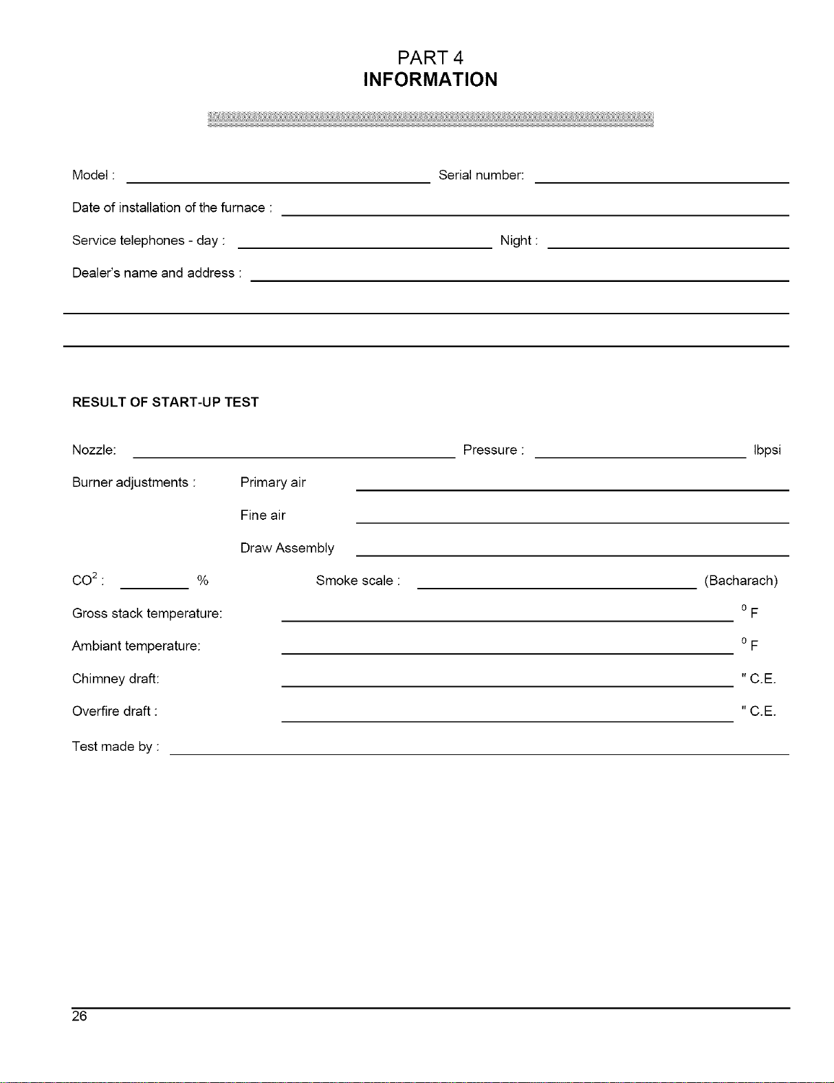
PART 4
INFORMATION
Model:
Date of installation of the furnace :
Service telephones - day :
Dealer's name and address :
RESULT OF START-UP TEST
Nozzle:
Burner adjustments :
Primary air
Fine air
Draw Assembly
Serial number:
Night :
Pressure :
Ibpsi
CO2 : %
Gross stack temperature:
Ambiant temperature:
Chimney draft:
Overfire draft :
Test made by :
Smoke scale :
(Bacharach)
o F
o F
"C.E.
"C.E.
26
Page 26

Model : OLR
RATING AND PERFORMANCE
Firing rate
Pump pressure (PSIG)
Input (BTU/h)
Heating capacity, chimney installation (BTU/h)
Heating capacity, side-w all installation (BTU/h)
Minimum - maximum temperature rise
Stack draft, (Chimney), (Side-wall)
Overfire pressure (chimney), (Side-w all)
BECKE'n" BURNER, CHIMNEY INSTALLATION
Low firing rate baffle
Static disc, model
Nozzle (Delavan)
Combustion air adjustment (shutter / band)
RIELLO BURNER, CHIM NEY INSTALLATION
Nozzle (Delavan)
Combustion air adjustment (turbulator / damper)
RIELLO BURNER, CHIM NEY INSTALLATION
Nozzle (Delavan)
Combustion air adjustment (turbulator / damper)
BECKETF BURNER, SIDE-WALL INSTALLATION
Nozzle (Delavan)
Combustion air adjustment (screw / dial) or (dial only)
RIELLO BURNER, SIDE-WALL INSTALLATION
Nozzle (Delavan)
Combustion air adjustment (turbulator / damper)
ELECTRICAL SYSTEM
Volts - Hertz - Phase
Operating voltage range
Rated voltage Amp
Minimum ampacity for wiring sizing
Max. fuse size (Amps)
Control transformer
Ext. control power available, cooling and accessories
BLOWER DATA
Blow er speed at 0.5" W.C. static pressure
Blow er speed at 0.25" W.C. static pressure
Maximum cooling, speed
Maximum cooling, tons @ 0.5" W.C.
Motor (HP) / number of speeds
Blow er w heel size (in.)
Filter quantity and size
TABLE # 4.1
Technical specifications
OLR105A12B
.50
100
70 000
59 200
59 400
(-0,035 to -0,06) (+0,04 to +0,16)
(0,00 to +0,035 +0,10 to +0,25)
AFG-F0 (tube insersion 5 1/8")
.63 .75
156 156
88 200 105 000
73 000 87 800
73 200 88 200
52-75 Degr. F
.72
145
100 800
84 200
119 000
98 000
98 000
(-0.035 to -0.06) (+0.04 to +0.22)
(-0.00 to +0.04) (+0.10 to +0.25)
AFG-F3, tube insersion 6 5/8")
Yes Yes Yes
2 3/4 #3383 2 3/4 #3383 2 3/4 #3383
0.50-70A 0.50-70A 0.60-70B
2 3/4 #3383 2 3/4 #3383 2 3/4 #338:
0.75-70B 0.85-70B 1.00-70B
4.5/0 8/0 7.5/0
40-F3 (tube insersion 5 3116")
o.5o-6oA060-60A
40-F5 (tube insersion 6 5/8")
0.75-70B 0.85-70B 1.00-70B
0/3 0/4
R35,3 (tube insersion 5 3/16")
0.50-60A0.60-60A
0/3 0/4
AFII-85 (tube insersion 4 15/16")
0.50 - 60W 0.50 - 60W 0.60 - 60W
3/1.5 3/3 3/4.5 _.
40-BF3 (tube insersion 5 3/16")
0.50-60w 0.60-60w
0/8 _ 0/7.5
115-60-1 115-60-1
104- 132 104- 132
12,2 15.7
13.7 18.1
15 20
40 Va 40 Va
30 Va 30Va
MED-LO MED-HI HIGH HIGH MED-LO
LOW MED-HI MED-HI MED-HI MED-LO
LOW MED-LO MED-HI HIGH MED-LO
1.5 2 2.5 3 3.5
1/3 HP/4 speeds
10 X 10
(1)20 X 20
AFII-150 (tube insersion 6 5/8")
0.75-70B 0.85-70B 1.00-70B
40-BF5 (tube insersion 6 5/8")
0.75-70B 0.85-70B 1.00-70B
OLR160B20B
0.85
130
0.97 1.14
130 130
135 800 159 600
110 000 127 000
110 000 127 000
50-80 Degr.F
Yes Yes Yes
5/0 6.5/0 10/0
1/2 1/2.5 1/3
N/A N/A N/A
N/A N/A N/A
2.75 4.25 6.75
1 /3 1 /4 2/4.5
MED-HI HIGH
MED-HI MED-HI
MED-HI HIGH
4 5
3/4 HP / 4 speeds
12X10
(2) 16 X 24
TABLE # 5.1
Air delevery - CFM with air filter
OLR105A12B OLR160B20B
EXTERNAL STATIC PRESSURE WITH AIR FILTER EXTERNAL STATIC PRESSURE WITH AIR FILTER
SPEED 0.25 0.5 0.25 0.5
LOW 850 700 1100 1020
MED-LO 940 750 1360 1350
MED-HI 1090 1000 1625 1540
HIGH 1390 1300 2100 1850
27
Page 27

Model : OUF / NOUF
RATING AND PERFORMANCE
Firing rate
Pump pressure (PSIG)
Input (BTU/h)
Heating capacity, chimney installation (BTU/h)
Heating capacity, side-w all installation (BTU/h)
Minimum - maximum temperature rise
Stack draft, (Chimney), (Side-wall)
Overfire pressure (chimney), (Side-w all)
BECKEFF BURNER, CHIMNEY INSTALLATION
Low firing rate baffle
Static disc, model
Nozzle (Delavan)
Combustion air adjustment (shutter / band)
RIELLO BURNER, CHIM NEY INSTALLATION
Nozzle (Delavan)
Combustion air adjustment (turbulator / damper)
BECKETT BURNER, SIDE-WALL INSTALLATION
Nozzle (Delavan)
Combustion air adjustment (screw / dial) or (dial only)
RIELLO BURNER, SIDE-WALL INSTALLATION
Nozzle (Delavan)
Combustion air adjustment (turbulator / damper)
ELECTRICAL SYSTEM
Volts - Hertz - Phase
Operating voltage range
Rated voltage Amp
Minimum ampacity for wiring sizing
Max. fuse size (Amps)
Control transformer
Ext. control power available, cooling and accessories
BLOWER DATA
Blower speed at 0.5" W.C. static pressure
Blower speed at 0.25" W.C. static pressure
Maximum cooling, speed
Maximum cooling, tons @ 5" W.C.
Motor (HP) / number of speeds
Blow er w heel size (in.)
Filter quantity and size
TABLE # 4.2
Technical specifications
OUF105A12B / NOUF105A12B
.5O
100
70 000
58 900
59 800
(-0,035 to -0,06) (+0,04 to +0,16)
(0,00 to +0,035) (+0,10 to +0,25)
AFG-F0 (tube insersion 5 1/8")
Yes Yes Yes
2 3/4 #3383 2 3/4 #3383 2 3/4 #3383
0.50-70A 0.50-70A 0.60-70B
4.5/0 8/0 7.5/0
40-F3 (tube insersion 5 3116")
.63 .75
156 156
88 200 105 000
73 500 86 100
74 600 87 800
52- 75 Degr. F
.72
145
100 800
83 900
o.5o-6oA0.60-60A
OlS o14
AFII-85 (tube insersion 4 15116")
0.50 - 60W 0.50 - 60W 0.60 - 60W
3/1.5 3/3 3/4.5
40-BF3 (tube insersion 5 3/16")
_. 0.50-60W _ 0.80-60W
0/6 _ 0/7.5
115-60-1 115-60-1
104- 132 104- 132
15.4 16.9
17.7 19.5
20 20
40 Va 40 Va
30 Va 30 Va
LOW LOW MED-HI MED-HI MED-LO MED-HI
LOW LOW MED-LO MED-LO MED-LO MED-LO
LOW MED-LO MED-HI HIGH MED-LO MED-HI
2 2.5 2.5 3 3.5 4
1/2 HP/4 speeds
10X10
(1) 20 X 20
OUF160B18B / NOUF160B18B
.65
130
119 000
96 000
97 000
50-80 Degr. F
(-0,035 to -0,6) (+0,04 to +0,18)
(0,00 to +0,04) (+0,10 to +0,25)
AFG-F3 tube insersion 6 5/8")
Yes Yes Yes
2 3/4 #3383 2 3/4 #3383 2 3/4 #3383
0.75-70B 0.85-70B 1.00-70B
5/0 6,5/0 10/0
40-F5 (tube insersion 6 5/8")
0.75-70B 0.85-70B 1.00-70B
0/2.5 0/2.8 0/3.9
AFII-150 (tube insersion 6 5/8")
0,75-70B 0,85-70B 1,00-70B
2,75 4,25 6,0
40 - BF5 (tube insersion 6 5/8"}
0,75-70B 0,85-70B 1,00-70B
0/3,75 0/4 0/4,875
0.85 HP/4 speeds
(1) 24 X 24
.97
130
135 800
110 000
110 000
12 X 10
1.14
130
159 600
127 000
127 000
HIGH
MED-HI
HIGH
5
TABLE #5.2
Air delevery - CFM with air filter
OUF105A12B / NOUF105A12B OUF160B18B / NOUF160B18B
EXTERNALSTATICPRESSUREWITH AIR FILTER EXTERNALSTATIC PRESSUREWITH AIR FILTER
SPEED 0.25 0.5 0.25 0.5
LOW 960 920 1080 990
MED-LO 1100 1000 1350 1310
MED-HI 1300 1150 1605 1510
28
Page 28

Model : OLF / NOLF
RATING AND PERFORMANCE
Firing rate
Pump pressure (PSIG)
Input (BTU/h)
Heating capacity, chimney installation (BTU/h)
Heating capacity, side-w all installation (BTU/h)
Minimum - maximum temperature rise
Stack draft, (Chimney), (Side-w all)
Overfire pressure (chimney), (Side-w all)
BEOKETT BURNER, CHIM NEY INSTALLATION
Low firing rate baffle
Static disc, model
Nozzle (DeIavan)
Combustion air adjustment (shutter / band)
RIELLO BURNER, CHIMNEY INSTALLATION
Nozzle (DeIavan)
Combustion air adjustment (turbuIator / damper)
BECKETT BURNER, SIDE-WALL INSTALLATION
Nozzle (DeIavan)
Combustion air adjustment (screw / dial)
RIELLO BURNER, SIDE-WALL INSTALLATION
Nozzle (DeIavan)
Combustion air adjustment (turbuIator / damper)
ELECTRICAL SYSTEM
Volts - Hertz - Phase
Operating voltage range
Rated voltage Amp
Minimum ampacity for wiring sizing
Max. fuse size (Amps)
Control transformer
Ext. control power available, cooling and accessories
BLOWER DATA
Blow er speed at 0.5" W.C. static pressure
Blow er speed at 0.25" W.C. static pressure
Maximum cooling, speed
Maximum cooling, tons @ 5" W.C.
Motor (HP) / number of speeds
Blow er w heel size (in.)
TABLE # 4.3
Technical specifications
.50
100
70 000
59 200
59 400
Yes
2 3/4 #3383
0.50- 70A
4.5/0
0.50 - 60W
3/1.5
LOW HIGH
LOW HIGH
LOW HIGH
1.5 3
OLF105A!2B / NOLF!05A12B
.63 .75
156 156
88 200 105 000
73 000 87 800
73 200 88 200
52 - 75 Degr. F
(-0,035 to -0,06 +0,04 to +0,16)
/0,00 to +0,035) +0,10 to +0,25)
AFG-F0 (tube insersion 5 1/8")
Yes No
2 3/4 #3383 2 3/4 #3383
0.50 - 70A 0.60 - 70B
8/0 7.5/0
40-F3 {tube insersion 5 3/16")
0.50 - 60A 0.60 - 60A
0/3 0/4
AFII-85 Itube insersion 4 15116" 1
0.50 - 60W 0.60 - 60W
3/3 3/4.5
40-BF3 (tube insersion 5 3/16")
0.50 - 60W
0/6
115-60-1
104 132
12,2
13.7
15
40 Va
30 Va
MED-HI HIGH
MED-HI HIGH
MED-LO MED-HI
2 2.5
1/3 HP/4 speeds
10 X 10
.72
145
100 800
84 200
0.60 - 60W0/7.5
SPEED
LOW
MED-LO
MED-HI
HIGH
TABLE # 5.3
Air delevery - CFM with air filter
OLF105A12B / NOLF105A12B
EXTERNAL STATIC PRESSURE WITH AIR FILTER
0.25
84O
96O
1050
1300
0.5
77O
800
98O
1200
29
Page 29

z,
19 3/4"
FIGURE# 5.1
Model: OLR105A12B
€1"
5" DIAM FLUE
32 _
DNS-0571 Rev B
FIGURE # 5.2
Model: OLR160B20B
_2 l/B"
23 3/4"
l
I
40"
213/4 _
J
6" DIAM. FLUE
<k
)
DNS-0573 Rev. B
3O
Page 30

5" DIAM_ FLUE_
FIGURE# 5.3
Model: OUF105A12B
19 5/4"
I
° °I 1
48 _
15.750"
DNS-0568 Rev. C
6" DIAM. FLUEs.
2.4 _
FIGURE # 5.4
Model: OUF160B18
25"
25 5/4
, i-
58
DNS-0572 Rev C
1 8"
[]
_ q ,
2.4 '_
31
Page 31

5" DIAM. FLUE
FIGURE# 5.5
Model : OLF105A12B
0
o
o
32"
DNS-0570 Rev. B
5" DIAM, FLUE
2,,$"
FIGURE # 5.6
Model: NOUF105A12B
33 1/2" _-
_19 3/4" _
DNS-0674 Rev C _
32
15.750"
o
Page 32

6" DIAM. FLUE_
FIGURE # 5.7
Model: NOUF160B18B
,_7 'p
23 3/4"
,, )J
L_ L
58 /4"
V
DNS-0675 Rev D
5" DIAM.
FLUE
FIGURE # 5.8
Model: NOLF105A12B
5S 1/4"
19 5/4"
52"
DNS-0676 Rev C
=
33
Page 33

FIGURE# 6
Wiring diagram, OLR105A12B, OLR160B20B, OUF105A12B, NOUF105A12B, OUF160B18B,
NOUF160B18B_ OLF105A12B & NOLF105A12B
COOLING HEATING
FAN LIMIT
HEAT/COOL
THERMOSTAT
LOW SPEED
BLOWER SWITCH!
COMPRESSOR
BR
CONTACTOR
I
II
Blower Motor
N HUM.
N E.A.C.
NeutrGI I
L1 HUM.
L1 E.A,C.
L1 L_
115
BECKEqW BURNER AFG
BECKETT BURNER AFII
BK {]Z]
RD
WH
BK
RD RD
WH
SPDT RELAY
TRANSFORMER
(
BK/ RD W * BURNER WIRES
SEE DIAGRAM BELOW
BK CCS
RIELLO BURNER R40 F
BK BK
RD GREY
WH WH
RIELLO BURNER R40 BF
(LOAD)
BK
ELECTRICAL CONNECTION MANDATORY.
(DIRECT VENT APPLICATION ONLY)
E.A.C. = ELECTRONIC AIR CLEANER
(WITH AIR PROVING SWITCH),
WIRING BY OTHERS
FACTORY WIRING (115 VOLTS)
FACTORY WIRING (24 VOLTS)
>k_. MAINTAIN 2" MIN SEPARATION
BEq_/EEN THESE WIRES.
RD
WH
DNS-0447 Rev. I
34
Page 34

PARTS LIST
Model : OLR105A12B Serial # > 264 000
DETAIL "A"
/
DNS-0564 Rev. D
1 Complet heat exchanger
2 Top heat exchanger
3 Combustion chamber
4 Gasket, heat exchanger
5 Bottom heat exchanger
6 Hexagonal flange nut 3/8-16N0 brass
7 Gasket panel, peep hole
8 Division panel
9 Plenum diqder
10 Floor
11 Left side panel ass'y
12 Left side panel insulation
13 Top rear panel
14 Blower door ass'y
15 Air filter drawer
16 Right side panel ass'y
17 Right side panel insulation
18 Right filter support
19 Left filter support
20 Gasket, extruded 1/2" X 1/8" x 25'
21 Front panel ass'y
22 Front panel insulation
23 Washer 3/8" AA zinc
24 Hexagonal nut 3/8-16NC brass
25 Washer, peep hole
26 Hexagonal flange nut 3/8-16NC brass
27A 5" breech plate
27B 3" breech plate
28 Gasket, breech plate
29 Electrical box cover (without cosmetic
30 Electrical box
31 Rocker switch SPST
B30756-02
B30465-02
B30414
B30517
B30757
F070001
B30753
B30488
B30478
B30472
B30509-02
B30493-04
B30511
B30512
B30507
B30509-01
B30493-03
B30479-01
B30479-02
J06L001
B30768-01
B30762
F06F005
F07F024
B30752
F070001
B30459
B30515
B30415-02
B40085
B30514
L07F003
32 Fan limit control R021005
33 Transformer 120/24 VAC / 40 VA K03040
34 Relay SPDT 24VAC L01H009
35 Terminal strip, 6 positions L05F011
36 Blower weel 10 X 10 Z01L002
37 Capacitor holder B01024
38 5 MF capacitor L011001
39 Blower electrical kit B30057
40 Screw cable tie F11F007
41 Blower support bracket B30473
42 1/3 HP direct drive motor B01890-01
43 Motor mount ass'y B01888
44A Blower 10 X 10 Z011004
44B Blower ass'y B01405-03
45 Rubber grommet #19 Z01F006
46 Sealing strip B01291-01
47 Strip B30188-02
48 Gasket, access cover B30415-01
49 Flange plate B30487
50 Hexagonal flange nut 3/8-16N0 brass F070001
51 Access cover B30486
52 Rocker switch SPST L07F016
53 Terminal strip, 6 positions A00336
54 Floor baffle B30480
55 Gasket, access cover B30415-02
56 Gasket, burner B30534
57 Gasket, access cover B30415-02
58 Gasket, sealing plate B30533
59A Peep hole kit K30011
59B Over[ire pressure test kit K30012
60 Gasket, glass B30055
61 Glass, neoceram B30041-01
35
Page 35

PARTS LIST
Model : OLR160B20B Serial # > 264 000
DETAIL "A"
/
/
©
DETAIL
DNS-0567 Rev D
1 Comptet heat exchanger
2 Top heat exchanger
3 Combustion chamber
4 Hexagonal flange nut 3/8-16NC brass
5 Gasket, panel, peep hole
6 Bottom heat exchanger
7 Gasket, heat exchanger
8 Gasket, heat exchanger
9 Gasket, heat exchanger
10 Front baffle
11 Rear baffle
12 Di_sion panel
13 Plenum divider
14 Floor baffle
15 Floor
16 Left side panel ass'y
17 Left side panel insulation
18 Left bottom filter support
19 Left top filter support
20 Strip
21 Sealing strip
22 Blower door ass'y
23 Air filter drawer
24 Top rear panel
25 Gasket, breech plate
26A 5" breech plate
26B 4" breech plate
27 Hexagonal flange nut 3/8-16NC brass
28 Gasket, extruded 1/2" X 1/8" x 25'
29 Right side panel ass'y
30 Right side panel insulation
31 Right bottom filter support
32 Right top filter support
B30786-02
B30596
B30584
F070001
B30753
B30787
B30532
B30534
B30415-02
B30665
B30664
B30666
B30669
B30481
B30663
B30680-02
B30686-02
B30668-02
B30667
B10256-99
B01291-02
B30683
B30678
B30682
B30589-01
B30646
B30647
F070001
J06L001
B30680-01
B30686-01
B30668-01
B30667
33 Front panel ass'y
34 Front panel insulation
35 _Vasher, peep hole
36 _Vasher 3/8" AA zinc
37 Hexagonal nut 3/8-16NC brass
38 Flange plate
39 Hexagonal flange nut 3/8-16NC brass
40 Access cover
41 Electrical box cover (without cosmetic)
42 Terminal strip, 6 positions
43 Rocker switch SPST
44 Rocker switch SPST
45 Electrical box
46 Fan limit control
47 Transformer 120/24 VAC / 40 VA
48 Terminal strip, 6 positions
49 Relay SPDT 24VAC
50 Rubber grommet #19
51 Blower support bracket
52 Blower electrical kit
53 Strain release bushing SR-9P-2
54 Capacitor holder
55 15 MF capacitor
56 Blower weel 12 X 10
57A Blower 12 X 10
57B Blower ass'y
58 Motor mount ass'y
59 3/4 HP direct drive motor
60A Peep hole kit
60B Overfire pressure test kit
61 Gasket, glass
62 Gasket, neoceram
B30782-01
B30780
B30752
F06F005
F07F024
B30676
F070001
B30486
B40085
L05F011
L07F016
L07F003
B30514
R021005
K03040
A00336
L01H009
Z01F006
B01756
B30530-01
L041010
B01024
L011005
Z01L003
Z011008
B01406-05
B01889
L061004
K30011
K30012
B30055
B30041-01
36
Page 36

PARTSLIST
Model : OUF105A12B Serial # > 264 000
DETAIL "A"
DETAIL "A"
DNS-0563 Rev. D
1 Complet heat exchanger
2 Top heat exchanger
3 Gasket, heat exchanger
4 Combustion chamber
5 Bottom heat exchanger
6 Hexagonal flange nut 3/8-16NC brass
7 Gasket panel, peep hole
8 Division panel
9 Floor
10 Baffle
11 Rear panel ass'y
12 Rear panel insulation
13 Right side panel ass'y
14 Right side panel insulation
15 Front panel ass'y
16 Front panel insulation
17 Blower door ass'y
18 Door handle
19 Left side panel ass'y
20 Left side panel insulation
21A 5" breech plate
21B 3" breech plate
22 Gasket, breech plate
23 Hexagonal flange nut 3/8-16N0 brass
24 Hexagonal nut 3/8-16NC brass
25 Washer 3/8" AA zinc
B30756-01
B30465-01
B30517
B30414
B30757
F070001
B30753
B30431
B30430
B30426
B30457
B30419
B30458-01
B30418
B30760-01
B30761
B30455
Z99F050
B30458-02
B30418
B30459
B30515
B30415-02
F070001
F07F024
F06F005
26 Terminal strip, 6 positions
27 Electrical box cover (without cosmetic)
28 Relay SPDT 24VAC
29 Transformer 120/24 VAC / 40 VA
30 Fan limit control
31 Rocker switch SPST
32 Electrical box
33 Blower side rails
34 Blower weel 10 X 10
35 1/2 HP direct drive motor
36 Blower electrical kit
37 Capacitor holder
38 7.5 MF capacitor
39 Motor mount ass'y
40 Sealing strip
41A Blower 10 X 10
41B Blower ass'y
42 Blower slide support
43 Washer, peep hole
44 Rocker switch SPST
45 Terminal strip, 6 positions
46 Gasket, burner
47A Peep hole kit
47B Overfire pressure test kit
48 Gasket, glass
49 Glas, neoceram
L05F011
B40085
L01H009
K03040
R021005
L07F003
B30514
B30433
Z01L002
L06H004
B30096
B01024
L01i002
B01888
B01291-01
Z01i004
B01405-02
B30513
B30752
L07F016
A00336
B30534
K30011
K30012
B30055
B30041-01
37
Page 37

PARTSLIST
Model : OUF160B18B Serial # > 264 000
DETAIL
@
DNS-0566 Rev D
1 Complet heat exchanger
2 Top heat exchanger
3 Combustion chamber
4 Hexagonal flange nut 3/8-16N0 brass
5 Gasket, heat exchanger
6 Bottom heat exchanger
7 Rear baffle
8 Front baffle
9 Top baffle
10 Division panel
11 Blower slide support
12 Floor
13 Left side panel ass'y
14 Left side panel insulation
15 Rear panel ass'y
16 Rear panel insulation
17 Hexagonal flange nut 3/8-16N0 brass
18 Breech plate
19 Gasket, access co'_r
20 Gasket, access co'_r
21 Right side panel ass'y
22 Right side panel insulation
23 Gasket panel, peep hole
24 Gasket, burner
25 Gasket, breech plate
26 Front panel ass'y
27 Front panel insulation
28 Blower door ass'y
29 Door handle
30 Washer 3/8" AA zinc
B30786-01
B30597
B30584
F070001
B30532
B30787
B30619
B30618
B30639
B30627
B30625
B30628
B30653-02
B30658
B30652
B30659
F070001
B30487
B30415-01
B30415-02
B30653-01
B30658
B30753
B30534
B30589-01
B30781-01
B30779
B30651
Z99FO50
F06F005
J
31 Hexagonal nut 3/8-16NC brass
32A 5" breech plate
32B 4" breech plate
33 Hexagonal flange nut 3/8-16N0 brass
34 Electrical box
35 Relay SPDT 24VAC
36 Transfon'ner 120/24 VAC / 40 VA
37 Fan limit control
38 Rocker switch SPST
39 Electrical box cover (without cosmetic)
40 Washer, peep hole
41 .85 HP direct drive motor
42 Motor mount ass'y
43 Terminal strip, 6 positions
44 Blower electrical kit
45 Blower wheel 12 X 10
46 Sealing strip
47 Blower side rails
48A Blower 12 X 10
48B Blower ass'y
49 Capacitor holder
50 10 MF capacitor
51 Rocker switch SPST
52 Terminal strip, 6 positions
53 Gasket, sealing plate
54A Peep hole kit
54B Overfire pressure test kit
55 Gasket, glass
56 Glass, neocerarn
F07F024
B30646
B30647
F070001
B30514
L01H009
K03040
RO21005
L07F003
B40085
B30752
L06K001
B01889
L05F011
B30530
Z01L003
B01291-01
B30626
Z011008
B02167-01
B01024
L011003
L07F016
A00336
B30533
K30011
K30012
B30055
B30041-01
38
Page 38

%
PARTSLIST
Model : OLF105A12B Serial # > 264 000
DETAIL "A"
DNS-0565 Rev. D
mm_ ¸ Eii!l
1
Complet heat exchanger
2
Top heat exchanger
3
Combustion chamber
4
Gasket, heat exchanger
5
Bottom heat exchanger
6
Hexagonal flange nut 3/8=16NC brass
7
Gasket panel, peep hole
8
Division panel
9
Plenum divider
10
Floor
11
Left side panel ass'y
12
Left side panel insulation
13
Top rear panel
14
Blower door ass'y
15
Air filter drawer
16
Right side panel ass'y
17
Right side panel insulation
18
Right filter support
19
Left filter support
2o
Gasket, extruded 1/2" X 1/8" X 25'
21
Front panel ass'y
22
Front panel insulation
23
Washer 3/8" AA zinc
24
Hexagonal nut 3/8-16NC brass
25
Washer, peep hole
26
Hexagonal flange nut 3/8=16NC brass
27A
5" breech plate
27B
3" breech plate
28
Gasket, breech plate
29
Electrical box cover (without cosmetic)
B30756-01
B30465-01
B30414
B30517
B30757
F070001
B30753
B30477
B30478
B30472
B30504-02
B30493-02
B30506
B30512
B30507
B30504-01
B30493-01
B30479-01
B30479-02
B30483
B30767-01
B30761
F06F005
F07F024
B30752
F070001
B30459
B30515
B30415-02
B40085
30 Electrical box
31 Rocker switch SPST
32 Fan limit control
33 Transformer 120/24 VAC / 40 VA
34 Relay SPDT 24VAC
35 Terminal strip, 6 positions
36 Blower wee110 X 10
37 Capacitor holder
38 5 MF capacitor
39 Blower electrical kit
40 Screw cable tie
41 Blower support bracket
42 1/3 HP direct drive motor
43 Motor mount ass'y
44A Blower 10 X 10
44B Blower ass'y
45 Rubber grommet #19
46 Sealing strip
47 Strip
48 Rocker switch SPST
49 Terminal strip, 6 positions
50 Gasket, breech plate
51 Gasket, burner
52 Rear baffle
53 Front baffle
54A Peep hole kit
54B Overfire pressure test kit
55 Gasket, glass
56 Glass, neoceram
B30514
L07F003
R021005
K03040
L01H009
L05F011
Z01L002
B01024
L011001
B30057
F11F007
B30473
B01890-01
B01888
Z011004
B01405-03
Z01F006
B01291-01
B30188-02
L07F016
A00336
B30415-02
B30534
B30490
B30480
K30011
K30012
B30055
B30041-01
39
Page 39

PARTSLIST
Model : NOUF105A12B Serial # > 264 000
DETAIL "A"
\
DNS-0681 Rev B
1 Complet heat exchanger
2 Top heat exchanger
3 Gasket, heat exchanger
4 Combustion chamber
5 Bottom heat exchanger
6 Hexagonal flange nut 3/8-16NC brass
7 Gasket panel, peep hole
8 Division panel
9 Floor
10 Baffle
11 Rear panel ass'y
12 Rear panel insulation
13 Right side panel ass'y
14 Right side panel insulation
15 Front panel ass'y
16 Front panel insulation
17 Blower door ass'y
18 Door handle
19 Left side panel ass'y
20 Left side panel insulation
21A 5" breech plate
21B 3" breech plate
22 Gasket, breech plate
23 Hexagonal flange nut 3/8-16NC brass
24 Hexagonal nut 3/8-16NC brass
25 Washer 3/8" AA zinc
26 Terminal strip, 6 positions
27 Electrical box cover (without cosmetic)
28 Relay SPDT 24VAC
B30756-01
B30465-01
B30517
B30414
B30757
F070001
B30753
B30431
B30430
B30426
B30457
B30419
B30458-01
B30418
B30760-01
B30761
B30455
Z99F050
B30458-02
B30418
B30459
B30515
B30415-02
F070001
F07F024
F06F005
L05F011
B40085
L01H009
\
/
29 Transformer 120/24 VAC / 40 VA
30 Fan limit control
31 Rocker switch SPST
32 Electrical box
33 Blower side rails
34 Blower weel 10 X 10
35 1/2 HP direct drive motor
36 Blower electrical kit
37 Capacitor holder
38 7.5 MF capacitor
39 Motor mount ass'y
40 Sealing strip
41A Blower 10 X 10
41B Blower ass'y
42 Blower slide support
43 Washer, peep hole
44 Rocker switch SPST
45 Terminal strip, 6 positions
46 Gasket, burner
47 Front door, vestibule
48 Right panel, vestibule
49 Left panel, vestibule
50 Top panel, vestibule
51 Bottom panel, vestibule
52 Draft regulator
53A Peep hole kit
53B Overfire pressure test kit
54 Gasket, glass
55 Glass, neoceram
K03040
R021005
L07F003
B30514
B30433
Z01L002
L06H004
B30096
B01024
L011002
B01888
B01291-01
Z011004
B01405-02
B30513
B30752
L07F016
A00336
B30534
B40293
B30725
B30726
B30723
B30724
Z06F001
K30011
K30012
B30055
B30041-01
4O
Page 40

PARTSLIST
Model : NOUF160B18B Serial # > 264 000
DNS-0680 Rev B
1 Complet heat exchanger B30786-01
2 Top heat exchanger B30597
3 Combustion chamber B30584
4 Hexagonal flange nut 3/8-16N0 brass FOTOOOl
5 Gasket, heat exchanger B30532
6 Bottom heat exchanger B30787
7 Gasket panel, peep hole B30619
8 Front baffle B30618
9 Top baffle B30639
10 Di_4sion panel B30627
11 Blower slide support B30625
12 Floor B30628
13 Left side panel ass'y 830653-02
14 Left side panel insulation 830658
15 Rear panel ass'y 830652
16 Rear panel insulation 830659
17 Hexagonal flange nut 3/8-16N0 brass FOTOOOl
18 Breech plate B30487
19 Gasket, access cover B30415-01
20 Gasket, access cover B30415-02
21 Right side panel ass'y B30653-01
22 Right side panel insulation B30658
23 Gasket panel, peep hole B30753
24 Gasket, burner B30534
25 Gasket, breech plate B30589-01
26 Front panel ass'y B30781-01
27 Front panel insulation B30779
28 Blower door ass'y B30651
29 Door handle Z99FO50
30 Washer 3/8" AA zinc FO6FOO5
31 Hexagonal nut 3/8-16N0 brass FO7FO24
32A 5" breech plate B30646
328 4" breech plate B30647
33 Hexagonal flange nut 3/8-16NC brass
34 Electrical box
35 Relay SPDT 24VAC
36 Transformer 120/24 VAC / 40 VA
37 Fan limit control
38 Rocker switch SPST
39 Electrical box cover (without cosmetic)
40 Washer, peep hole
41 .85 HP direct drive motor
42 Motor mount ass'y
43 Terminal strip, 6 positions
44 Blower electrical kit
45 Blower wheel 12 X 10
46 Sealing strip
47 Blower side rails
48A Blower 12 X 10 ZOllOO8
48B Blower ass'y B02167-01
49 Capacitor holder 801024
50 10 MF capacitor LO11003
51 Rocker switch SPST LO7FO16
52 Terminal strip, 6 positions A00336
53 Gasket, sealing plate B30533
54 Front door, vestibule B40295
55 Right panel, vestibule B30632
56 Left panel, vestibule B30633
57 Top panel, vestibule B30732
58 Bottom panel, vestibule B30728
59 Draft regulator ZOGFOOl
6OA Peep hole kit K3OOl 1
GOB OveF_ire pressure test kit K30012
61 Gasket, glass B30055
62 Glass, neoceram B30041-01
FOTOOOl
B30514
LOIHOO9
KO3O4O
RO21OO5
LOTFOO3
B40085
B30752
LOGKOOl
B01889
LO5FOll
B30530
ZOILOO3
B01291-01
B30626
41
Page 41

%
DETAIL A
PARTSLIST
Model : NOLF105A12B Serial # > 264 000
DETAIL "A"
DNS-0679 Rev B
1 Complet heat exchanger B30756-01 88 Transformer 120/24 VAC / 40 VA K08040
2 Top heat exchanger B30465-0! 34 Relay SPDT 24VAC L01H009
3 Combustion chamber B30414 35 Terminal strip, 6 positions L05F0! !
4 Gasket, heat exchanger B30517 36 Blower weeI 10 X 10 Z01L002
5 Bottom heat exchanger B30757 37 Capacitor holder B01024
6 Hexagonal flange nut 3/8-16N0 brass F070001 38 5 MF capacitor L011001
7 Gasket panel, peep hole B80758 89 Blower electrical kit 880057
8 Division panel B30477 40 Screw cable tie F11F007
9 Plenum divider B30478 41 Blower support bracket 830473
10 Floor B30472 42 1/3 HP direct drive motor 801890-01
11 Left side panel ass'y B30504-02 43 Motor mount ass'y 801888
12 Left side panel insulation B30493-02 44A Blower 10 X 10 Z011004
13 Top rear panel B30506 448 Blower ass'y B01405-03
14 Blower door ass'y B30512 45 Rubber grommet #19 Z01F006
15 Air filter drawer B30507 46 Sealing strip 801291-01
16 Right side panel ass'y B30504-01 47 Strip 830188-02
17 Right side panel insulation B30493-0! 48 Rocker switch SPST L07F016
18 Right filter support B30479-0! 49 Terminal strip, 6 positions A00336
19 Left filter support B30479-02 50 Gasket, breech plate 830415-02
20 Gasket, extruded 1/2" X 1/8" X25' B30483 51 Gasket, burner 830534
21 Front panel ass'y B30767-01 52 Rear baffle 830490
22 Front panel insulation B30761 53 Front baffle 830480
23 Washer 3/8" AA zinc F06F005 54 Front door, vestibule 840292
24 Hexagonal nut 3/8-16N0 brass F07F024 55 Right panel, vestibule 830729
25 Washer, peep hole B30752 56 Left panel, vestibule 830730
26 Hexagonal flange nut 3/8-16N0 brass F070001 57 Top panel, vestibule 830723
27A 5" breech plate B30459 58 Bottom panel, vestibule 830724
278 3" breech plate B30515 59 Draft regulator Z06F001
28 Gasket, breech plate B30415-02 60A Peep hole kit K30011
29 Electrical box cover (without cosmetic) B40085 608 Overfire pressure test kit K30012
30 Electrical box B30514 61 Gasket, glass 830055
31 Rocker switch SPST L07F003 62 Glass, neoceram 830041-01
32 Fan limit control R021005
42
 Loading...