

ICP OHB5-F059-085-3, OLB6-R097-130-5, OHB6-F097-130-5, OLB5-F059-085-3 Installation Instructions And Owner's Manual
Page 1
il ii
I
OLB5-R /
OLB6-R
OLB5-F
i_!ii
OHB5-F /
OHB6-F
DNS_0562 Rev A
UPFLOW OIL WARM
AIR FURNACE
Save these instructions for future reference.
Printed in Canada 2001/12/03
445 01 4083 02
X40083 Rev. D
Page 2
PART 1
INSTALLATION
2) SAFE INSTALLATION REQUIREMENTS
1)
SAFETY LABELLING AND SIGNAL WORDS
Installation or repairs made by unqualified persons
can result in hazards to you and others. Installation
MUST conform with codes or, in the absence of
local codes, with codes of the country having
jurisdiction.
The information contained in this manual is
intended for use by a qualified service technician
familiar with safety procedures and equipped with
the proper tools and test instruments.
Failure to carefully read and follow all instructions
in this manual can result in furnace malfunction,
property damage, personal injury and/or death.
1.1) Danger, Warning and Caution:
The signal words DANGER, WARNING and CAUTION are used to
identify levels of hazard seriousness. The signal word DANGER is
only used in product labels to signify an immediate hazard. The signal
words WARNING and CAUTION will be used on product labels and
throughout this manual and other manuals that may apply to the
product.
1.2) Signal Words:
DANGER - Immediate hazards which WILL result in death or serious
injury.
WARNING - Hazards or unsafe practices which COULD result in
death or injury.
CAUTION - Hazards or unsafe practices which COULD result in
personal injury or product or property damage.
1.3) Signal Words in Manuals:
The signal word WARNING is used throughout this manual in the
following manner:
The signal word CAUTION is used throughout this manual in the
following manner:
CAUTION
Fire hazard
The furnace must be installed in a level position,
never where it will slope to the front.
If the furnace were installed in that position, oil
could drain into the furnace vestibule and create a
fire hazard, instead of draining properly into the
combustion chamber.
NOTE: It is the personal responsibility and obligation of the customer
to contact a qualified installer to ensure that the installation is
adequate and conforms to governing codes and ordinances.
a. This furnace is NOT approved for installation in mobile homes,
trailers or recreation vehicles.
b. You must have a sufficient supply of fresh air for combustion and
ventilation to the area in which the furnace is located.
c. Do NOT use this furnace as a construction heater or to heat a
building that is under construction.
d. Use only the Type of fuel oil approved for this furnace (see
Rating Plate on unit). Overfiring will result in failure of heat
exchanger and cause dangerous operation.
e. Visually check all oil line joints for signs of wetness, which would
indicate a leak.
f. Connect furnace to a side-wall terminal or chimney.
g. The points in Part 2 "Operation" are vital to the proper and safe
operation of the heating system. Take the time to be sure they
are all done.
h. Follow the rules of the NFPA Pamphlet No.31 (for USA) and B-
139 (for Canada) or local codes for locating and installing the oil
storage tank.
i. Follow a regular service and maintenance schedule for efficient
and safe operation.
Page 3
j. Beforeservicing,allowfumacetocool.Alwaysshutoffelectricity
andfueltofurnacewhenservicing.Thiswillpreventelectrical
shockorburns.
k. Sealsupplyandreturnairducts.
I. TheventsystemMUSTbecheckedtodeterminethatitisthe
correcttypeandsize.
m. Installcorrectfiltertypeandsize.
n. UnitMUSTbeinstalledsoelectricalcomponentsareprotected
fromdirectcontactwithwater.
2.1) Safety Rules:
Your unit is built to provide many years of safe and dependable
service providing it is properly installed and maintained. However,
abuse and/or improper use can shorten the life of the unit and create
hazards for you, the owner.
a. The U.S. Consumer Product Safety Commission recommends
that users of oil-burning appliances install carbon monoxide
detectors. There can be various sources of carbon monoxide in
a building or dwelling. The sources could be gas-fired clothes
dryers, gas cooking stoves, water heaters, furnaces, gas-fired
fireplaces, wood fireplaces, and several other items. Carbon
monoxide can cause serious bodily injury and/or death.
Therefore, to help alert people of potentially dangerous carbon
monoxide levels, you should have carbon monoxide detectors
listed by a nationally recognised agency (e.g. Underwriters
Laboratories or Intemational Approval Services) installed and
maintained in the building or dwelling (see Note).
b. There can be numerous sources of fire or smoke in a building or
dwelling. Fire or smoke can cause serious bodily injury, death,
and/or property damage. Therefore, in order to alert people of
potentially dangerous fire or smoke, you should have fire and
smoke detectors listed by Underwriters Laboratories installed
and maintained in the building or dwelling (see Note below).
I NOTE: The manufacturer of your furnace does not test any detectors
and makes no representations regarding any brand or type of
detector.
I CAUTION
Insure that the area around the combustion air intake
terminal is free of snow, ice and debris.
I CAUTION
The air pressure switch MUST be used when the
furnace is vented by the side-wall.
CAUTION
Do not use any commercially available soot remover.
This furnace has fiber type refractory combustion
chamber. Normal servicing of this unit does not require
cleanings of the combustion chamber. Use extreme
care if for any reason you have to work in the area of
the combustion chamber,
2.2) Freezing Temperature and Your
Structure:
Your unit is equipped with safety devices that may keep it from
operating if sensors detect abnormal conditions such as clogged
exhaust flues.
Freeze warning.
Turn off water system.
If your unit remains shut off during cold weather the
water pipes could freeze and burst, resulting in
serious water damage.
If the structure will be unattended during cold weather you should take
these precautions.
a.
b.
Turn off main water supply into the structure and drain thewater
lines if possible. Open faucets in appropriate areas.
Have someone check the structure frequently during cold
weather to make sure it is warm enough to prevent pipes from
freezing. Suggest they call a qualified service agency, if
required.
2.3) Installation regulation:
All local and national code requirements governing the installation of
oil burning equipment, wiring and flue connections MUST be followed.
Some of the codes that may be applicable are:
CSA B139 INSTALLATION CODE FOR OIL
BURNING EQUIPMENT
NFPA31 INSTALLATION OF OIL BURNING
EQUIPMENT
ANSltNFPA 90B WARM AIR HEATING AND AIR
CONDITIONING SYSTEMS
ANSItNFPA 70 NATIONAL ELECTRICAL CODE
CSA C22.2 No3 CANADIAN ELECTRICAL CODE
Only the latest issues of the above codes should be used.
3) LOCATING THE FURNACE
CAUTION
Check carefully your furnace upon delivery for any
evidence of damage that may have occurred during
shipping and handling. Any claims for damages or lost
parts must be made with the Transport Company,
3.1) Location:
Locate the furnace as closely as possible to the chimney or vent
terminal, providing ample clearance to permit easy accessibility for
cleaning the inside of the furnace, the removal of filters, blower,
motors, controls and flue connections.
The OCF is certified for reduced clearances to combustibles, which
means it can be installed in an alcove, closet or crawl space by
obeying the clearances specified on the rating plate.
In the downflow position, the OCF is certified for use on combustible
floors only when the accessory No CFB-1 "Combustible Floor Base" is
used in the installation.
Page 4
Inthehorizontal(airleftorright)position,theOCFiscertifiedforuse
oncombustiblefloorsonlywhentheaccessoryNo.HFB-1'l-lorizor_al
Floor Base" is used in the installation.
In the horizontal (air left or right) position, the OCF can be suspended
using an angle iron frame with threaded rod hangers provided the
weight of the frame and furnace considered in the support
calculations.
For an attic installation, keep the building at least 12" away from any
opening in the furnace enclosure as some insulation can be
combusted.
However, do not install furnace directly on carpet or other combustible
material which can trapped air under the floor.
The furnace must be installed level for safe quiet operation.
CAUTION
Do NOT operate furnace in a corrosive atmosphere
containing chlorine, fluorine or any other damaging
chemicals. Refer to Part 1, section 5.2.
TABLE #1
Minimum Installation clearances from combustible materials (Chimney installation*)
LOCATION APPLICATION " ODH5-F059-085-3 AND OCF105A12B
Furnace 1"
Sides Supply plenum, warm air duct within 6 ft of furnace 1"
Back Furnace 1"
Top Fumace casing or plenum 1"
Bottom Fumace- combustible floor ** 0....
Front Furnace 24"
* See Part 1 section 4.3 for Direct Vent application clearance.
** Combustible floor requires accessory bases CFB-1 or HFB-1.
4) VENTING
4.1) General:
The furnaces can be vented in several ways:
Chimney Vented:
Using the Beckett AFG or Riello 40-F burner, the furnaces can be
chimney vented with or without a barometric damper. The unit will be
operated at a negative over fire draft and stack draft.
DV-2000 TM venting system for maximum efficiency, and without the
use of a side-wall power ventor. The unit will be operated at a positive
overfire draft and stack draft.
4.2) Chimney installations:
The oil furnaces, when set up for chimney venting, are cedilied for use
with L-vent, A-vent, tile-lined and metal-liner-tile-lined chimneys, and
can be vented both with and without a barometric draft damper.
However, the furnace has not been certified without the barometric
damper when it is to be co-vented with another oil-fired appliance,
such as a water heater.
Poison carbon monoxide gas, fire and explosion
hazard.
Read and follow all instructions in this section.
Failure to properly vent this furnace can result in
property damage, personal injury and/or death.
Poison carbon monoxide gas hazard
Never co-vent the furnace with another combustion
appliance when side-wall venting.
To do so may result in asphyxiation and death to
the occupants
Side-wall Vented:
Using the Beckett AFII or Riello 4O-BF burner with the integral pre and
post purge controls, the system can be side-wall vented with the new
With a barometric damper:
The appliance may be installed in a chimney of the proper size and
adequate chimney base temperature as specified in the Installation
Code. When a barometric damper is used, the basement air entering
the damper reduces the possibility of vent condensation. The relevant
excerpt from the code is found in this section - Use it as aguide _4qen
local or national codes do not exist. To increase the chimney base
temperature, add a vent connector insulation is a possibility.
Poison carbon monoxide gas hazard
Never install a hand operated damper in the vent
pipe. However, any Underwriters Laboratories
listed electrically operated automatic type vent
damper may be installed if desired. Be sure to
follow instructions provided with vent damper.
Read and follow all instructions in this section.
Failure to properly vent this furnace or other
appliances can result in property damage, personal
injury and/or death.
Page 5
Without a barometric damper:
Due to the lack of dilution air that would ordinarily be drawn into the
barometric damper, the dew point of the flue gasses is raised. To
offset the increased tendency for vent condensation, the chimney
must be lined. The liner must be insulated according to the insulating
procedure recommended by the manufacturer of the liner. Also, the
vent connector should be as short as possible and either be of double
wa!l construction, or be of single wall construction insulated with 1" of
insulation.
CAUTION
When the furnace (chimney installation) is co-vented
with other combustion appliances such as a water
heater, the allowable venting materials (i.e. L-Vent etc.)
for use with those appliances should also be
investigated.
I NOTES: Thermal resistance values for typical chimneys are asfollows:
R2 (2 ft 2 ,hr ,°F / Btu):
R3 (3 ft t ,hr ,°F / Btu):
R6 (6 ft 2 ,hr ,°F / Btu):
clay-lined masonry, A-vent
metal liner in clay-lined
Masonry
metal or clay-lined masonry
with R4.5 (4.5 ft2 *hr *°F / Btu)
insulation between liner and
masonry (e.g. 2 in. of
expanded mica or 1 3/8 in. of
high density glass fibreboard.)
Applying the Table:
If a fumace with 0.60 USGPH nozzle is to be connected to a 20 ft. tall
clay-lined masonry chimney, the thermal resistance of this chimney
type is R2, which is less than R6. The actual firing rate at 156 psig is
1.25 x .60 = .75. Therefore this table shall apply as:
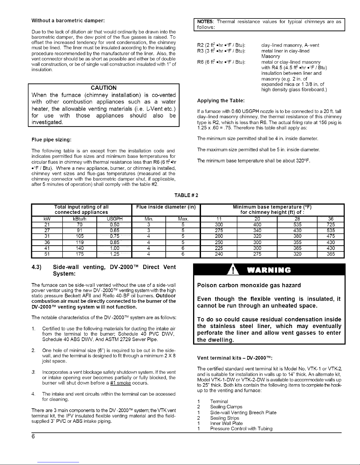
Flue pipe sizing:
The minimum size permitted shall be 4 in. inside diameter.
The following table is an except from the installation code and
indicates permitted flue sizes and minimum base temperatures for
circular flues in chimney with thermal resistance less than R6 (6 ftt*hr
*°F / Btu). Where a new appliance, burner, or chimney is installed,
chimney vent sizes and flue-gas temperatures (measured at the
chimney connector with the barometric damper shut, if applicable,
after 5 minutes of operation) shall comply with the table #2.
The maximum size permitted shall be 5 in. inside diameter.
The minimum base temperature shall be about 320°F.
TABLE # 2
Total input rating of all
connected appliances
kW " kBtu/h
21 70
27 91
31 105
36 119
41 140
51 175
USGPH
0.50
0.65
0.75
0.85
1.00
1.25
Flue inside diameter(in) Minimum base temperature (°F)
for chimney height(if)of:
Min. " Max. " 11 ' 20 " 28 " 36
3 5 300 400 535 725
3 5 275 340 430 535
4 5 260 320 380 475
4 5 250 300 355 430
4 6 225 300 365 430
4 6 240 275 320 365
4.3) Side-wall venting, DV-2000 TM Direct Vent
System:
The furnace can be side-wall vented without the use of a side-wall
power ventor using the new DV -2000 TM venting system with the high
static pressure Beckett AFII and Riello 40-BF oil burners. Outdoor
combustion air must be directly connected to the burner of the
DV-2000 TM venting system w ill not function.
TM
The notable characteristics of the DV-2000 system are as follows:
2,
3,
4,
Certified to use the following materials for ducting the intake air
from the terminal to the burner; Schedule 40 PVC DWV,
Schedule 40 ABS DWV, And ASTM 2729 Sewer Pipe.
One hole of minimal size (6") is required to be cut in the side-
wall, and the terminal is designed to fit through a minimum 2 X 8
joist space.
Incorporates a vent blockage safety shutdown system. Ifthe vent
or intake opening ever becomes partially or fully blocked, the
burner will shut down before a #1 smoke occurs.
The intake and vent circuits within the terminal can be accessed
for cleaning.
TM
There are 3 main components to the DV-2000 system; the VTK vent
terminal kit, the IFV insulated flexible venting material and the field-
supplied 3" PVC or ABS intake piping.
Poison carbon monoxide gas hazard
Even though the flexible venting is insulated, it
cannot be run through an unheated space,
To do so could cause residual condensation inside
the stainless steel liner, which may eventually
perforate the liner and allow vent gasses to enter
the dwelling.
Vent terminal kits - DV-2000TM:
The certified standard vent terminal kit is Model No. VTK-1 or VTK-2,
and is suitable for installation in walls up to 14" thick. An altemate kit,
Model VTK-1-DW or VTK-2-DW is available to accommodate walls up
to 25" thick. Both kits contain the following items to complete the hook-
up to the venting and furnace:
1 Terminal
2 Sealing Clamps
1 Side-wall Venting Breech Plate
2 Sealing Strips
1 Inner Wall Plate
1 Pressure Control with Tubing
Page 6
2 InsulatedQuick-connectTerminals
3 StainlessSteelScrews
6 Selftappingstainlesssteelscrews
Insulatedflexible venting - DV-2000TM:
steel corrugated flexible liner surrounded by a thick insulation blanket
and covered with an outer layer of flexible corrugated aluminium
sleeve to protect the insulation. Splicing vent lengths together is
prohibited. The maximum and minimum continuous vent lengths
permitted for installation are:
The certified venting materials come in 3 lengths, Model No. IFV3-15,
IFV3-23 and IFV3-30 (or IFV4-15, IFV4-23 and IFV4-30 for 160
models) are corresponding to 15', 23' and 30' continuous lengths of
vent. The vent construction is coaxial and incorporates a stainless
5 feet minimum 30 feet maximum
TABLE # 3.1
Minimum clearances of side-wall venting (Models OLB5, OHB5, OLR105, OUF105, OLF105, NOUF105 and NOLF105)
PORTION OF VENT CANADA UNITED STATES
Vent pipe, from furnace breech to 1 foot downstream of furnace breech* 1/4" 3"
Vent pipe, up to vent terminal* ZERO 3"
Vent terminal ZERO ZERO
* Do not enclose venting.
TABLE # 3.2
Minimum clearances of side-wall venting (Models OHB6, OLB6, OLR160, OUF160 and NOUF160)
I PORTION OF VENT CANADA ETATS-UNIS I
Vent pipe, up to vent terminal* 3" 3"
Vent terminal ZERO ZERO
*Do not enclose venting.
Installation considerations - DV'2000TM:
Installation of side-wall venting - DV-2OOOTM:
Select a location for the vent terminal in accordance with all local and
national codes. The following requirements shall be considered to be
minimum requirements that can be overridden by stricter local and
national codes.
The vent shall not terminate:
a. directly above a paved sidewalk or paved driveway that is
located between two buildings, and that serves both buildings;
b. less than 7 feet above any paved driveway;
c. within 6 feet (in Canada) or 4 feet (in United States) of a window
or door, or mechanical air supply inlet to any building;
d. within 6 feet (in Canada) or 1 foot (in United States) from the
soffit of the roof of the structure.
e. above a gas meter/regulator assembly within 3 feet of a vertical
centerline of the regulator;
f. within 6 feet of any gas service regulator vent outlet, or within 3
feet of an oil tank vent, or an oil fill inlet;
g. within less than 1 foot above ground level;
h. 6 feet of any other combustion air inlet;
i. within 6 feet of a property line;
j. underneath a veranda, porch or deck;
k. so that the flue gases are directed at combustible material or any
openings of surrounding buildings that are within 6 feet;
I. less than 3 feet from an inside corner of an L-shaped structure;
m. so that the bottom of the vent termination opening is less than 1
foot above any surface that may support ice, snow, or debris;
n. so that the flue gases are directed toward brickwork, siding or
other construction, in such a manner that may cause damage
from heat or condensation from flue gases.
Cuts and abrasion hazard.
Always wear protective gloves and eye protection
when handling the vent material
The process of cutting and fitting the flexible
venting material exposes the installer to sharp
edges that could cause severe cuts to the skin.
Connection to the furnace breech - DV'2000TM:
1. Remove the standard breech plate by removing the brass nuts.
2,
Determine which direction the venting will be routed from the
furnace and then install the special side-wall venting breech plate
provided in the VTK Series vent kit so that the breech plate test
port will be accessible after vent installation. However, do not
install the breech plate with the test port pointing downward.
Tighten the brass nuts.
3,
The flexible venting has 4 pieces of corrugated spin sleeving that
has been temporarily screwed on over top of it. Remove the spin
sleeving completely by unscrewing it in a counter-clockwise
direction.
CAUTION
Most codes have a notwithstanding clause that states
that products of combustion shall not enter the dwelling
under any circumstances, even if all other code
requirements as to construction and location have been
complied with. The installer is ultimately responsible to
do whatever is necessary to ensure that flue gasses do
not enter the dwelling.
4,
5,
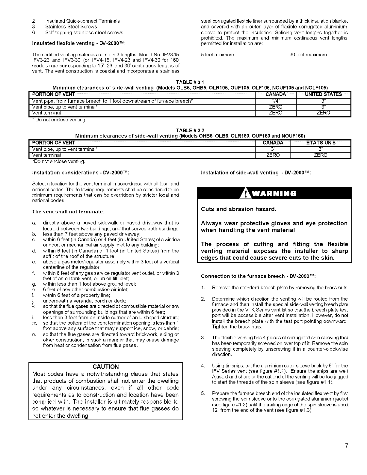
Using tin snips, cut the aluminium outer sleeve back by 5" for the
IFV Series vent (see figure #1.1). Ensure the snips are well
Ajusted and sharp or the cut end of the venting will be too jagged
to start the threads of the spin sleeve (see figure #1.1).
Prepare the furnace breech end of the insulated flex vent by first
screwing the spin sleeve onto the corrugated aluminium jacket
(see figure #1.2) until the trailing edge of the spin sleeve is about
12" from the end of the vent (see figure #1.3).
Page 7
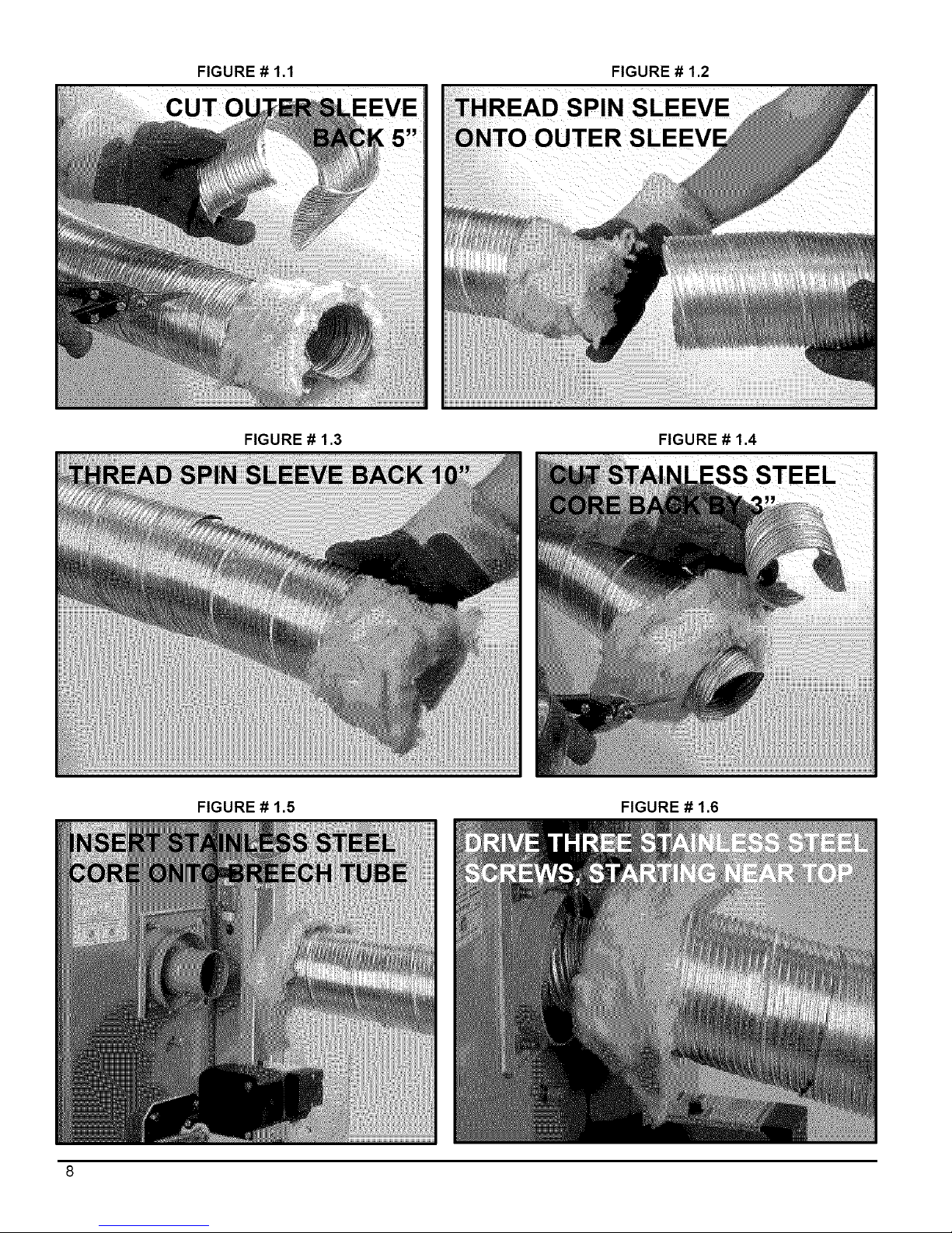
FIGURE # 1.1
EEVE
FIGURE # 1.2
SLEEVE
ITER SI
FIGURE # 1.3 FIGURE # 1.4
FIGURE # 1.5 FIGURE # 1.6
Page 8
FIGURE# 1.7 FIGURE# 1.8
FIGURE# 1.9 FIGURE#1.10
FIGURE# 1.11
Page 9
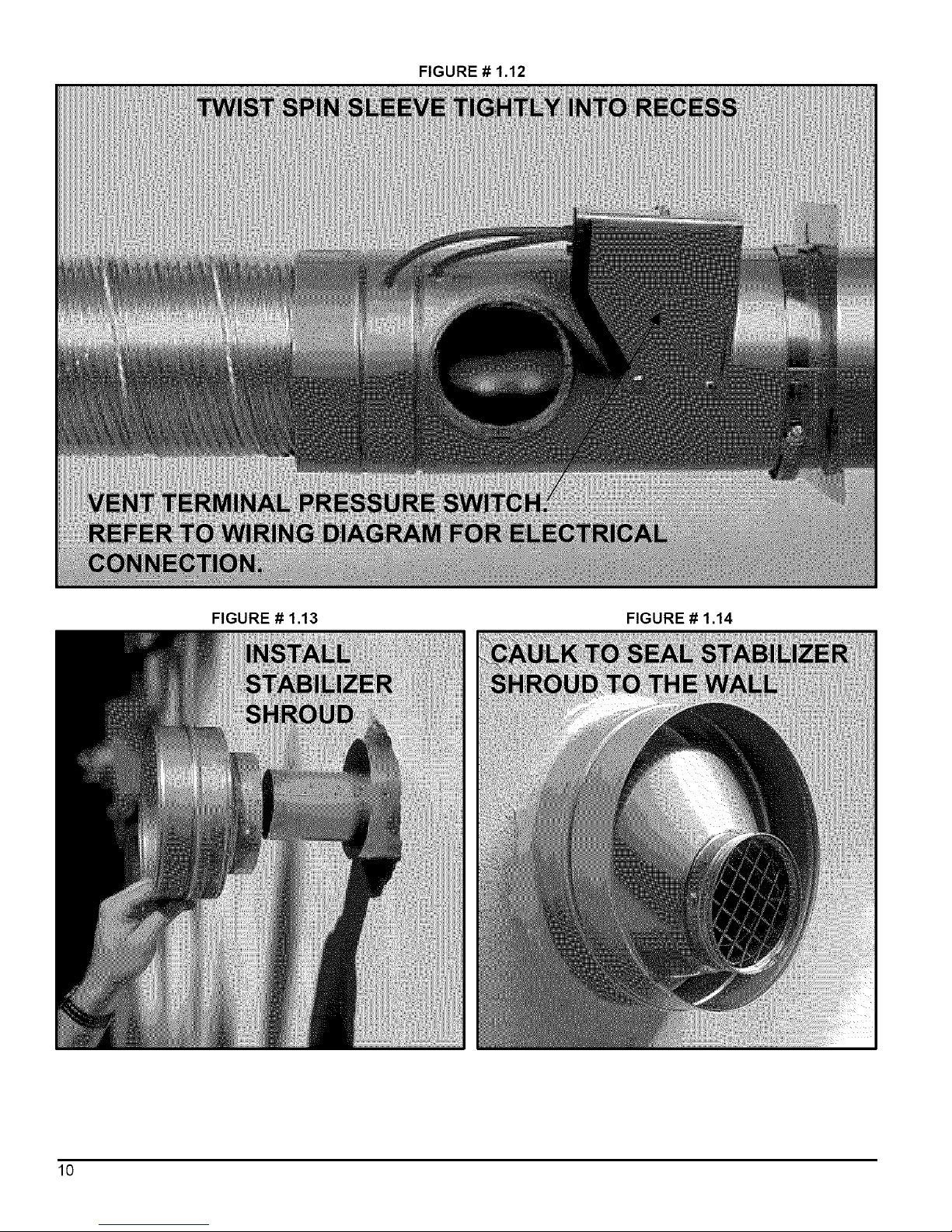
FIGURE # 1.12
FIGURE # 1.13 FIGURE # 1.14
10
Page 10
6. Pull the insulation back to expose the corrugated stainless steel
core.
7. Cut the corrugated stainless steel core back by 3" for the IFV
Series vent. You should now have about 3" of insulation hanging
out past the stainless steel core (see figure #1.4).
8,
Push the stainless steel core onto the breech pipe as far as it will
go (see figure #1.5) and mechanically attach the vent to the
breech using three of the #8 X 1/2" self-drilling screws provided
with the VTK Series kit. The screws should be equally spaced
around the circumference of the stainless steel core, starting with
the first screw at top dead center. Start the drill point of the
screws in the valleys of the corrugations at 3/8"-5/8" back from
the end of the stainless steel core, so the screw heads can be
properly sealed in the forthcoming operations (see figure #1.6).
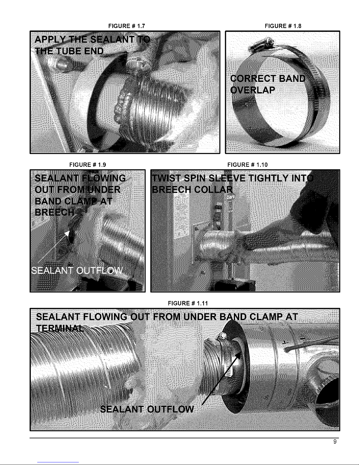
9,
With the stainless steel core now firmly attached to the breech,
tear off one green gum-sealing strip from the backing strip. Wrap
the seal strip around the joint, always keeping the centerline of
the seal strip over the line where the corrugated stainless steel
core makes the transition to the smooth outer surface of the
breech pipe. In other words, the seal strip must be centered over
the joint. After wrapping the seal strip around once, allow 1/2"
overlap and tear offthe residual length (see figure #1.7).
10. Break the residual length of seal strip in to 3 equal parts and stuff
them onto the screw heads of the stainless steel self-drilling
screws so that the screw heads are completely covered.
11. Two stainless steel band clamps are provided in the VTK Series
kits. Position one stainless steel band clamp over the gum seal
joint so that the edge of the clamp closest to the breech lines up
with the edge of the gum seal that is closest to the breech.
Ensure that the band will close with an action of one strip sliding
over the other - not under the gearhead of the draw clamp (see
figure #1.8). Tighten the band clamp with considerable torqueto
cause the gum sea! be squeezed into all crevices and to ooze
out of the end of the clamp closest to the breech (see figure
#1.9). The gum will eventually become rubbery.
12. The seal is permanent and should never need to be
disconnected as the breech plate can be removed for cleaning
and inspection using the 4-bolt joint.
13. Tuck the vent insulation into the breech collar.
14. Screw the spin sleeve tightly into the breech cellar for a finished
appearance. Wrap the other end of the spin sleeve with
aluminium tape to cover any metal burrs that may be present
(see figure #1.10).
15. Bend the venting into the desired radius coming offthe breech.
Connection to the vent terminal - DV-2000TM:
Prepare the terminal end of the insulated flex vent by first
screwing the spin sleeve onto the corrugated aluminium jacket
until the trailing edge of the spin sleeve is about 19" from the end
of the vent.
2. Using sharp tin snips, cut the aluminium outer sleeve back by 5"
for the IFV Series vent
3. Pull the insulation back to expose the corrugated stainless steel
core.
4. Cat the corrugated stainless steel core back by 3" for the IFV
Series vent. You should now have about 3" of insulation hanging
out past the stainless steel core.
5,
Push the stainless steel core onto the pipe on the back of the
terminal as far as it will go and mechanically attach the vent to
the terminal using three of the #8 X 1/2" self-drilling screws
provided with the VTK Series kit. The screws should be equally
spaced around the circumference of the stainless steel core,
starting with the first screw at top dead center. Start the drill point
of the screws in the valleys of the corrugations at 3/8"-5/8"back
from the end of the stainless steel core.
8,
With the stainless steel core now firmly attached to the terminal,
tear off the other green gut_sealing strip from the backing strip.
Wrap the sea! strip around the joint, always keeping the
centerline of the seal strip over the line where the corrugated
stainless steel core makes the transition to the smooth outer
surface of the terminal pipe. After wrapping the seal strip around
once, allow 1/2" overlap and tear off the residual length.
7. Break the residual length of seal strip in to 3 equal parts and stuff
them onto the screw heads of the stainless steel self-drilling
screw s so that the screw heads are completely covered.
8.
Position the other stainless steel band clamp over the gum seal
joint so that the edge of the clamp closest to the terminal lines up
with the edge of the gum sea! that is closest to the terminal.
Tighten the band clamp with considerable torque to cause the
gum seal be squeezed into all crevices and to ooze out of the
end of the clamp closest to the terminal (see figure #1.11 ).
9.
The seal is permanent and should never need to be
disconnected as the end of the terminal can be opened for
cleaning and inspection by removing the screened end-cone
assembly. Tuck the vent insulation into the recess in the terminal
body.
10.
Screw the spin sleeve tightly into the recess for a finished
appearance. Wrap the other end of he spin sleeve with
aluminium tape to cover any metal burrs that may be present
(see figure #1.12).
1I. Bend the venting into the desired radius coming off the terminal.
Installing terminal in the wail - DV'2000TM:
1. Cut a 6" hole in the side-wall in accordance with the location
considerations outlined in the previous section.
2.
Fasten the wall plate to the inside-wall using 4 field-provided
fasteners appropriate for the material behind the wall plate.
Depending on the angle of access, the pressure control bracket
may need to be removed to access the top right wall plate screw
hole. For concrete and block, Tapcon TM screws or equivalent are
recommended. Install the wall plate so that the top of the hole in
the wall plate is positioned 1/8" lower than the top of the 6" hole
in the wall. This will accommodate the proper downward slope of
the terminal, in the direction from the inside to the outside.
3. Remove the 2 screws fastening the end cone in place and
remove the cone.
4. Remove the 2 screws fastening the stabiliser shroud in place and
remove the stabiliser shroud.
5. Insert the main body of the terminal through the wall plate so that
the end of the terminal extends about 2" past the outside wall.
6. Install the stabiliser shroud and replace the two mounting screws.
(see figure #1.13).
7,
For concrete and block wall installations in particular, If it appears
that the flange on the back of the stabiliser shroud is not large
enough to cover the irregularities in the hole, a field fabricated
wall plate can be constructed out of 304,316, or 316L stainless
steel.
8. Silicone seal the circumference of the joint where the stabiliser
shroud connects to the main body of the terminal.
9. Apply caulking to the back plate of the stabiliser shroud and push
the terminal back firmly against the wall, making sure the
pressure switch is located at the top, in a horizontal position.
11
Page 11
10. While pushing down gently on the top of the stabiliser shroud,
install the 3 stainless steel 2" screws provided with the kit to
secure the back of the shroud to the wall. Do not overtighten the
screws or it will distort the stabiliser shroud. The screws will not
be necessary in a concrete or block wall as the mortar can
provide positive positioning.
11. Tighten the clamp on the wall plate to secure the terminal in
position.
12. Apply more caulking all around the seam where the stabiliser
shroud meets the wall. It is important to have a good seal to
prevent water from entering the dwelling (see figure #1.14). A
considerable amount of caulking may be necessary for irregular
wall surfaces such as lapped siding.
13. Install the end cone and replace the two mounting screws.
14. Support the vent and intake air piping so that a 114" to 1/2"
downward slope (toward the outside) resultsforproperdrainage
out the terminal body.
Connection of combustion air piping to the terminal - DV-2000TM:
Refer to Part 1, section 5.3, Outdoor Combustion Air - Side-wall
Venting, DV-2000 TM for a complete description.
5) AIR FOR COMBUSTION
Poison carbon monoxide gas hazard.
Comply with ANSI/NFPA (in U.S.) or CSA (in
Canada) standard for the installation of Oil Burning
Equipment and applicable provision of local
building codes to provide combustion and
ventilation air.
Failure to provide adequate combustion and
ventilation air can result in personal injury and/or
death.
5.1) General:
Oil furnaces must have an adequate supply of combustion air. It is
common practice to assume that older homes have sufficient
infiltration to accommodate the combustion air requirement for the
furnace. However, home improvements such as new windows,dcors,
and weather stripping have dramatically reduced the volume of air
leakage into the home.
Home air exhausters are common. Bathroom and kitchen fans, power
vented clothes dryers, and water heaters all tend to create a negative
pressure in the home. Should this occur, the chimney become less
and less effective and can easily downdraft.
Heat recovery ventilation (HRV) systems are gaining in popularity. The
HRVs are not designed to supply combustion air. If not properly
balanced, a serious negative pressure condition could develop in the
dwelling.
5.2) Contaminated Combustion Air :
Installation in certain areas or types of structures will increase the
exposure to chemicals or Halogens which may harm the furnace.
12
These instances will require that only outside air for combustion.
The following areas or types of structures may contain or have
exposure to the substances listed below. The installation must be
evaluated carefully as it may be necessary to provide outside air for
combustion.
a. Commercial building.
b. Building with indoor pools.
c. Furnaces installed near chemical storage areas.
Exposure to these substances:
a. Permanent wave solutions for hair.
b. Chlorinated waxes and cleaners.
c. Chlorine based swimming pool chemicals.
d. Water softening chemicals.
e. De-icing salts or chemicals.
f. Carbon tetrachloride.
g. Halogen type refrigerants.
h. Cleaning solvent (such as perchloroethylene).
i. Printing inks, paint removers, varnishes, etc..
j. Hydrochloric acid.
k. Solvent cements and glues.
I. Antistatic fabric softeners for clothes dryers.
m Masonery acid washing materials.
5.3) Ducted outdoor combustion air:
Three burners are set up to duct outside combustion air directly to the
burner; the Beckett AFII and Riello 40-BF for side-wall venting using
the new DV -2000 TM venting system, and the Beckett AFG for use with
conventional chimney venting. The Riello 40-F is not suitable for
direct-connected outdoor air.
CAUTION
The use of ducted outside combustion air is mandatory
for the DV-2000 TM venting system. This system
operates on a balanced flue principle and will not
function properly if the combustion air piping is not
attached and sealed at all connections between the
vent terminal and burner inlet.
Outdoor combustion air kit - chimney venting:
The following kit has been certified for use on the appliance. The
component kits contain an important safety feature, namely a vacuum
relief valve, or VRV. During normal operation the burner aspirates
outdoor air. If the intake terminal ever becomes partially blocked or
fully blocked from ice or snow etc., the VRV will open to allow a
proportion of air from the dwelling to enter the burner thus maintaining
proper combustion. Once the blockage is removed, the V RVwill dose
and the burner will draw all air from the outdoors again:
CAS-2B Components (except air duct) for the Beckett AFG burner.
The kit includes the intake terminal, vacuum relief valve (VRV) and
special air boot connection with integral air adjustment means for the
AFG burner. The CAS-2B can be used with 4" galvanised air duct or
with 4" flexible aluminium air duct. It is recommended that the metallic
air ducting material should be insulated from the air intake up to 5 feet
from the burner to avoid condensation on the outside of the intake
pipe.
CAD-1 Air duct kit consists of 25 feet of insulated UL/ULC Listed
Class 1 air duct, and two 4" steel band clamps. The duct incorporates
a corrugated flexible aluminium core, surrounded by fibreglass
insulation covered with a vinyl vapour barrier.
Page 12
CAUTION
The CAS-2B does not turn the furnace installation into a
direct vent system. Therefore the building structure
must provide for adequate combustion air to be
delivered at the vacuum relief valve. The burner will
need to draw combustion air from the VRV's
surroundings if the intake ever becomes blocked.
Therefore non-direct vent installation codes must be
followed.
Comprehensive installation instructions are provided with the kit.
Outdoor combustion air - side-wall venting, DV-2000TM:
The new DV-2000 TM venting system is a sealed system and
completely isolates the furnace from the interior of the building. The
burner is totally unaffected by any pressure fluctuations within the
building which makes it ideal for tight home constructions.
The DV-2000 TMventing system requires additional parts, which are
not included with the kit. These additional parts must be constructed of
3" Schedule 40 PVC, PVOSWV, SDR-26,SDR-21, Septic Sewer
Pipe, or ABS plastic pipe, fittings and sealant. Also, installation
procedures, piping and fittings must conform to the following ANSI
/ASTM standards:
PVC ASTM D- 1785
SDR26, SDR21 ASTM D-2241
Septic Sewer Pipe ASTM D-2729
PVC-DWV ASTM D-2665
PVC Primer and
Solvent Cement ASTM D-2564
ABS Pipe and Fittings ASTM D-2235
Procedure for
Cementing Joints ASTM D-2855
Additional parts required (not included in VTK kit):
a. 3" elbow fitting as required
b. 3" plastic pipe
c. 3" 90°elbow, female-female(for terminal)
d. 3" female to 2" female reducer (Riello 40-BF burner only)
e. 2" 90°elbow, street type, female-male (Riello 40-BF bumer only)
f. 3" female-female PVC or ABS coupling (not sewer pipe) (Beckett
AFII burner only)
g. transition bushings to go from PVC or ABS to ASTM D2729
Septic Sewer Pipe (if applicable).
If PVC fittings are mixed with ABS fittings, use a solvent cement that is
approved for bonding the two plastics.
Intake pipe length - DV-2000TM:
The DV-2000 TMventing system has been certified for 120 equivalent
feet of 3" intake pipe. Count a 90°elbow as 10 equivalent feet and a
45°elbow as 5 equivalent feet in the calculation.
For Example:
1
2
3
2
1
1
5' Length = 5 equivalent feet
10' Lengths = 20 equivalent feet
90°elbows = 30 equivalent feet
45°elbows = 10 equivalent feet
90°elbow (terminal) = 10 equivalent feet
90°elbow (Riello Burner) = 10 equivalent feet
Total = 85 equivalent feet,
which is less than 120 feet, which is
acceptable.
Intake pipe installation - DV-2000TM:
Obtain the necessary additional parts, to complete the installation, and
start by piping at the burner. If the optional vestibule has been
installed, remove the appropriate knockouts in the side panels of the
vestibule. The lower 5" knockout inthe right hand panel is used for the
Beckett AFII bumer. The higher 5" knockouts on the right and left-
hand panels are for right or left connection to the Riello 40-BFbumer.
Beckett AFII burner:
Remove the burner intake cover by removing the 3 screws securing it
in place. Discard the cover and screws. Apply silicone liberally around
the end of a 3" coupling and fully insert the silicone end onto the
burner opening. Fasten securely with 3 self-tapping sheet metal
screws.
Riello 40-BF burner:
Fully insert the female end of the 2" 90 ° street elbow into the
combustion air fitting on top of the burner. Fasten securely with 3 self-
tapping sheet metal screws. Cement the 2" end of the 3" female to 2"
female reducer onto the male end of the 2" 90° street elbow. If these
parts are not easily obtained, use a 3" 90 ° street elbow with the male
end fitted over the combustion air fitting. The fitting will have to be
silicone sealed as the fit is a bit loose. Fasten securely with 3 self-
tapping sheet metal screws
Terminal connection:
Insert the 3" 90 ° female-female elbow onto the stainless steel air
intake fitting located on the right side of the vent terminal (viewing from
the rear). Fasten securely with 3 self-tapping sheet metal screws.
Intermediate piping:
Pipe as required between the terminal and the burner. Ensure that the
3" piping is routed and supported in accordance with local and national
codes. Obey minimum furnace clearances to combustibles when
routing any sections of 3" piping in the vicinity of the furnace. IfSeptic
Sewer Pipe is to be used, install transition bushings at the 3" female
ends of the fittings at the burner and at the terminal. Transition
bushings are readily available and are required because 3" PVC and
ABS pipes have a typical outside diameter of 3.5", whereas Septic
Sewer Pipe has a typical outside diameter of 3.25".
6) OIL TANKS AND LINES
Check your local codes for the installation of the tank and accessories.
At the beginning of each heating season or each year, verify the 11-
complete oil distribution system for oil leak.
A manual shut-off valve and an oil filter shall follow sequence from
tank to burner. Be sure that the oil line is clean before connecting to
the bumer. The oil line should be protected to eliminate any possible
damage. Installations having the fuel oil tank below the burner level
must employ a two pipe fuel supply system with an appropriate fuel
pump (more than 8' lift use 2 stage pump and more than 16' an
auxiliary pump).
Follow the pump instructions to determine the size of tubing you need
in relation of the lift, or the horizontal distance.
7) BURNER INSTALLATION
Mounting the burner:
a,
b.
The warm air furnace burner mounting plate has a four bolts
configuration.
Position the mounting gasket between the mounting flange and
the appliance burner mounting plate. Line up the holes in the
mounting flange with the studs on the appliance mounting plate
and securely bolt in place.
13
Page 13
After the burner is mounted:
a. Remove drawer assembly or air tube combination
b. Install nozzle (see specifications)
c. Confirm electrode settings
d. Make the electrical connections
e. Complete oil line connections
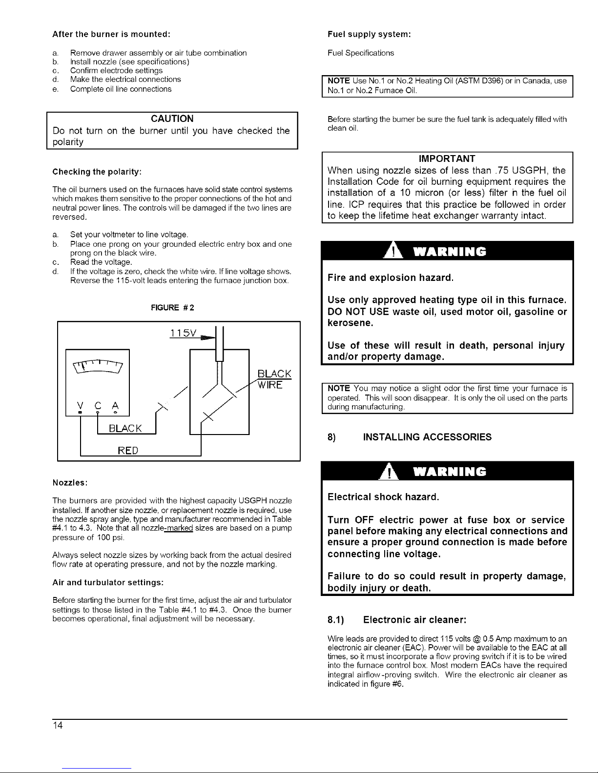
I CAUTION
Do not turn on the burner until you have checked the
polarity
Checking the polarity:
The oil burners used on the furnaces have solid state control systems
which makes them sensitive to the proper connections of the hot and
neutral power lines. The controls will be damaged if the two lines are
reversed.
a. Set your voltmeter to line voltage.
b. Place one prong on your grounded electric entry box and one
prong on the black wire.
c. Read the voltage.
d. If the voltage is zero, check the white wire. If line voltage shows.
Reverse the 115-volt leads entering the furnace junction box.
FIGURE # 2
1 15V
BLAC K
vcA
" m °
BLAC K
RED
Fuel supply system:
Fuel Specifications
I NOTE Use No.1 or No.2 Heating Oil (ASTM D396) or in Canada, use
No.1 or No.2 Furnace Oil.
Before starting the burner be sure the fuel tank is adequately filled with
clean oil.
IMPORTANT
When using nozzle sizes of less than .75 USGPH, the
Installation Code for oil burning equipment requires the
installation of a 10 micron (or less) filter h the fuel oil
line. ICP requires that this practice be followed in order
to keep the lifetime heat exchanger warranty intact.
Fire and explosion hazard.
Use only approved heating type oil in this furnace.
DO NOT USE waste oil, used motor oil, gasoline or
kerosene.
Use of these will result in death, personal injury
and/or property damage.
NOTE You may notice a slight odor the first time your furnace is
operated. This will soon disappear. It is only the oil used on the parts
during manufacturing.
8) INSTALLING ACCESSORIES
Nozzles:
The burners are provided with the highest capacity USGPH nozzle
installed. If another size nozzle, or replacement nozzle is required, use
the nozzle spray angle, type and manufacturer recommended in Table
#-4.1 to 4.3. Note that all nozzle-marked sizes are based on a pump
pressure of 100 psi.
Always select nozzle sizes by working back from the actual desired
flow rate at operating pressure, and not by the nozzle marking.
Air and turbulator settings:
Before starting the burner for the first time, adjust the air and turbulator
settings to those listed in the Table #-4.1 to #4.3. Once the burner
becomes operational, final adjustment will be necessary.
Electrical shock hazard.
Turn OFF electric power at fuse box or service
panel before making any electrical connections and
ensure a proper ground connection is made before
connecting line voltage.
Failure to do so could result in property damage,
bodily injury or death.
8.1) Electronic air cleaner:
Wire leads are provided to direct 115 volts @ 0.5 Amp maximum to an
electronic air cleaner (EAC). Power will be available to the EAC at all
times, so it must incorporate a flow proving switch if it is to be wired
into the furnace control box. Most modern EACs have the required
integral airflow-proving switch. Wire the electronic air cleaner as
indicated in figure #6.
14
Page 14
8.2) Humidifier:
Terminals are provided to direct 115 volts @ 1.0 Amp maximum to the
transformer powering the humidifier. The humidifier will be energised
anytime the blower is operating on the "Heating Speed". Wire the 115-
volt power as indicated in figure #6.
8.3) Air conditioning:
An air conditioning coil may be installed on the supply air side only.
Also, notwithstanding the evaporator coil manufacturer's instructions,
a minimum of 6 inches clearance must be allowed between the bottom
of the coil drain pan, and the top of the heat exchanger. Wire the
thermostat and condensing unit contactor as indicated in figure #6.
8.4) Ductwork and Filter:
Installation:
Design and install air distribution system to comply with Air
Conditioning Contractors of America manuals or other approved
methods that conform to local codes and good trade practices.
When furnace supply ducts carry air outside furnace area, seal return
air duct to furnace casing and terminate duct outside furnace space.
Install air conditioning cooling coil (evaporator)on down.steam side (in
the supply air plenum) or furnace.
If separate evaporator and blower unit is used, install good sealing
dampers for air flow control. Cold air from the evaporator coil going
through the furnace could cause condensation and shorten furnace
life.
I CAUTION
Dampers (purchased locally) MUST be automatic.
Poison carbon monoxide gas hazard.
Do NOT draw return air from inside a closet or
utility room. Return air duct MUST be sealed to
furnace casing.
Failure to properly seal duct can result in death,
personal injury and/or property damage.
Poison carbon monoxide gas hazard.
Install evaporator coil on the supply side of the
furnace ducting.
Evaporator coil installed in return side ducting can
cause condensation to f_rm inside heat exchanger
resulting in heat exchanger failure. This could
result in death, personal injury and/or property
damage.
PART 2
OPERATION
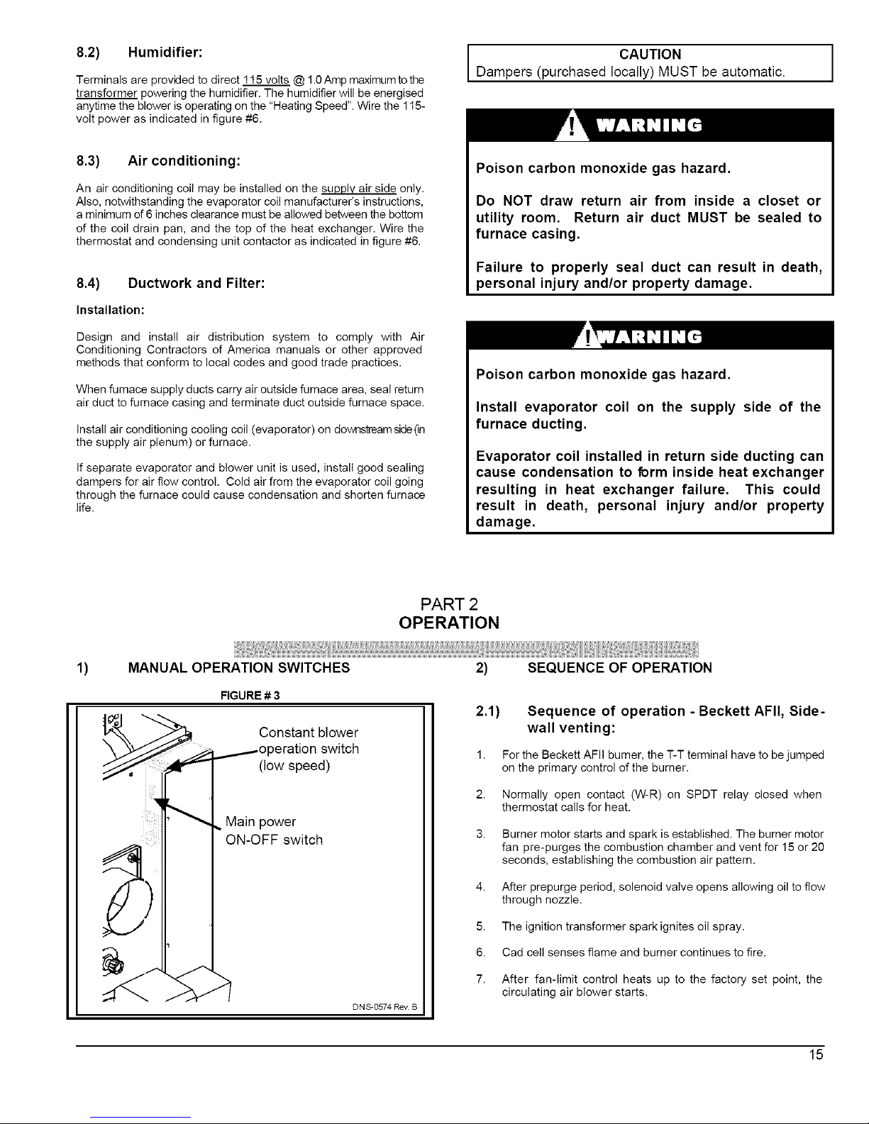
1)
MANUAL OPERATION SWITCHES
FIGURE # 3
Constant blower
3eration switch
(low speed)
Main power
ON-OFF switch
DNS-0574 Rev. B
2) SEQUENCE OF OPERATION
2.1) Sequence of operation - Beckett AFII, Side-
wall venting:
1. For the Beckett AFII burner, the T-T terminal have to be jumped
on the primary control of the burner.
2. Normally open contact (W-R) on SPDT relay closed when
thermostat calls for heat.
3. Burner motor starts and spark is established. The burner motor
fan pre-purges the combustion chamber and vent for 15 or 20
seconds, establishing the combustion air pattern.
4. After prepurge period, solenoid valve opens allowing oil to flow
through nozzle.
5. The ignition transformer spark ignites oil spray.
6. Cad cell senses flame and burner continues to fire.
7. After fan-limit control heats up to the factory set point, the
circulating air blower starts.
15
Page 15
8. The circulating air blower, burner motor and ignition transformer
remains on until the thermostat is satisfied. Also, the solenoid
valve remains open.
9. Thermostat is satisfied.
10. SPDT relay contacts open, solenoid valve closes, burner fan
motor post-purges the combustion chamber and vent for a pre-
set time (30 sec. to 4 min.). The ignition transformer also
continues to spark for this time period.
11. During the post-purge cycle, the fan-limit control cools down to
the factory set point of 90 degrees Fahrenheit, and the circulating
air blower turns off.
2.2) Sequence of operation - Riello 40-BF, Side-
wall Venting:
1. Normally open contact (W-R) on SPDT relay closed when
thermostat calls for heat.
2.
Burner motor starts. The burner motor fan pre-purges the
combustion chamber and vents for 10 seconds, establishing the
combustion air pattern. During this time the solenoid valve
holding coil pressure will be approximately 100 psig.
3. After prepurge period, solenoid valve opens, allowing oil to flow
through nozzle. At the same time, the burner motor's ignition coil
produces spark.
4. The ignition transformer spark ignites oil spray.
5. Cad cell senses flame and burner continues to fire. Ignition
transformer ceases sparking.
6. After fan-limit control heats up to the factory set point, the
circulating air blower starts.
7. The circulating air blower and burner motor remain on until the
thermostat is satisfied. Also, the solenoid valve remains open.
8. Thermostat is satisfied.
9. Relay contacts open, solenoid valve closes, and then the burner
fan motor post-purges the combustion chamber and vent for a
pre-set time (5" breech model only) (0 min. to 6 min.).
10. During the post-purge cycle, the fan-limit control BI-metal cools
down to the factory set point of 90 degrees Fahrenheit, and the
circulating air blower turns off.
NOTE: With burner relay contact open, the Riello 40-BF will post- I
purge when 115 volt power is applied to the burner.
1
2.3) Sequence of operation - Beckett AFG and
Riello 40-F, chimney:
1. For the AFG burner, the T-T terminal have to be jumped on the
primary control of the burner.
2. Normally open contact (W-R) on SPDT relay closed when
thermostat calls for heat.
3,
AFG Burner: The motor starts and spark is established. The
pump pressure builds and the poppet valve opens admitting fuel
to the nozzle. Pressure builds and poppet valve opens, allowing
oil to flow through nozzle.
40F: Burner motor starts. The burner motor fan pre-purgesthe
combustion chamber and vent for 10 seconds, establishing the
combustion air pattern. During this time the solenoid valve
16
4,
5.
6.
7.
8.
9.
10.
holding coil pressure will be approximately 100 psig. Solenoid
valve opens, allowing oil to flow through nozzle. At the same
time, the burner motor's ignition coil produces spark.
Spark ignites oil droplets.
Cad cell senses flame and burner continues to fire. Ignition
transformer ceases sparking (Riello R40-F).
After fan-limit control heats up to the factory set point, the
circulating air blower starts.
The circulating air blower and burner motor remain on until the
thermostat is satisfied (AFG). The ignition transformer continues
to spark (AFG). The solenoid valve remains open (R40-F).
Thermostat is satisfied.
SPDT relay contacts open, solenoid valve closes (R40-F), burner
fan motor shuts down. The ignition transformer ceases sparking
(AFG).
The fan-limit control BI-metal cools down to the factory set point
of 90 degrees Fahrenheit, and the circulating air blower turns off.
2.4) Sequence of operation - DV-2000 TM Venting
system:
Normal operation:
1. Before a call for heat the contacts of the pressure switch are
closed.
2,
3,
When the room thermostat calls for heat the normally open
contact W-R close and the burner blower starts and creates
suction in the intake piping circuit and a pressure in the vent
piping circuit.
The differential pressure setpoint of the pressure switch is not
exceeded and the thermostat circuit remains closed until the call
for heat has ended.
Abnormal operation:
Start-up:
1. When the room thermostat calls for heat the normally open
contact W-R close and the burner blower starts and creates
suction in the intake piping circuit and a pressure in the vent
piping circuit.
2.
3,
If there is a blockage in the intake or vent openings to cause a
pressure differential beyond the set point of the pressure switch,
then the thermostat circuit is opened and the burner will go into a
2 minute post-purge and then shut down.
After the post-purge, once the burner blower shuts down, the
pressure switch contacts will re-dose. Ifthe callfor heat remains,
the burner will re-start. If the blockage still exists, the thermostat
is again opened, and the burner post- purges again. The post-
purge function thus becomes an inherent anti-short cycling
device.
4,
5,
The unit will essentially go into a continuous re-cycling post-
purge mode with no heat being supplied to the dwelling, which
will prompt a call for service to the equipment.
During the re-cycling post-purges, if the blockage of the terminal
is removed, the burner will immediately fire up at the end of the
current post purge cycle.
Page 16
During operation:
If the terminal vent or intake openings become blocked to the point
where the set point of the pressure switch is exceeded, during a firing
cycle, the burner flame will shut down and the burner wiii go into the
indefinite recycling post-purge mode as described above, until the
blockage is removed.
3) CHECKS AND ADJUSTMENTS
3.1) General:
During initial start-up and subsequent yearly maintenance calls, the
furnace must be thoroughly tested.
Open the oil bleed port screw and start the burner. Allow the oil to
flush into a portable container for at least 10 seconds. Slowly close the
bleed screw - the oil should flow absolutely free of white streaks or
bubbles to indicate that no air is being drawn into the suction side of
the oil piping and pump. Tighten the bleed screw and the burner will
fire. Adjust the oil pressure as indicated in Table #-4.1 to #4.3.
IMPORTANT
The burner must be put in operation for at least 10
minutes before any test readings are taken. For new
installations, set up the burner to the settings (see table
#4.1 to 4.3), before firing. These are rough adjustments
but they will ensure that the burner will start and run
smoke-free in advance of the fine adjustments being
made.
3.2) Restart if Burner Should Stop:
1. Set thermostat lower than the room temperature.
2. Press the reset button on the burner primary control (relay).
3. With side-wall venting and Riello burner, set thermostat higher
than the room temperature for 10 seconds and set lower than
room temperature. This will start pre purge cycle. Repeat twice.
4. Set thermostat higher than the room temperature.
5. If the burner motor does not start or ignition fails, turn off the
disconnect switch and CALL YOUR SERVICEMAN
3.4) Perform the smoke / CO2 test:
1. For chimney installations, pierce a test hole in the smoke pipe
near the furnace breech. For side-wall vented installations,
remove the threaded cap from the extended test pipe that is
welded into 4-bolt breech plate. Insert the smoke test instrument
probe into the open hole.
2. Starting with a zero smoke reading, gradually reduce the burner
air setting until just a trace (#1 on Bacharach Scale) of smoke
results.
3. Take a CO2 sample at the same test location w here the smoke
sample was taken. Note the CO2 reading associated with the #1
smoke condition.
4. For chimney vented installations, adjust the burner air setting to
obtain a CO2 reading 1% lower than the reading associated with
the #1 smoke.
5. For side-wall vented installations, adjust the burner air setting to
obtain a CO2 reading 1.5% lower than the reading associated
with the #1 smoke.
6.
This method of adjusting the CO2 will allow adequate excess air
to ensure that the burner will burn clean for the entire heating
season, and will ensure proper calibration of the DV-2000 TM
blocked intake/vent safety shutdown system used in side-wall
venting applications.
3.5) Perform the supply air temperature rise test:
1. Operate the burner for at least 10 minutes.
2. Measure the temperature of the air in the return air plenum.
3.
Measure the temperature of the air in the largest trunk coming off
the supply air plenum, just "out of the line of sight" of the radiation
coming off the heat exchanger; 12" away from the plenum on the
main take-off usually satisfies this objective.
4. The temperature rise is calculated by subtracting the return air
temperature from the supply air temperature.
5.
If the temperature rise exceeds the temperature specified in table
#4.1 to #4.3, change to the next higher blower speed tap until the
temperature rise falls to at this temperature or below. If the
excessive temperature rise cannot be reduced by increasing fan
speed, investigate for ductwork restriction(s), dirty or improper air
filter, or overfiring caused by excessive pump pressure, or
inproper nozzle sizing.
I CAUTION
Do not attempt to start the burner when excess oil has
accumulated, when the furnace is full of vapour, or
when the combustion chamber is very hot.
3.3) Combustion chamber curing:
Some moisture and binders remain in the ceramic combustion
chambers after fabrication. It is important to clear the chamber of
these residues before testing. If you smoke test before curing, the
instrument may become damaged. To cure the chamber, run the unit
for 3 consecutive cycles, with 3 minutes of elapsed time in between
each cycle. Each burn cycle should be 3 minutes duration. The
exhaust will have a pungent odor and produce a white cloud ofsteam.
3.6) Vent temperature test:
1. Place a thermometer in the test hole located in the breech pipe.
2. The vent temperature should be between 400 and 575°F. If
not, check for improper air temperature rise, pump pressure,
nozzle size, or for a badly sooted heat exchanger.
17
Page 17
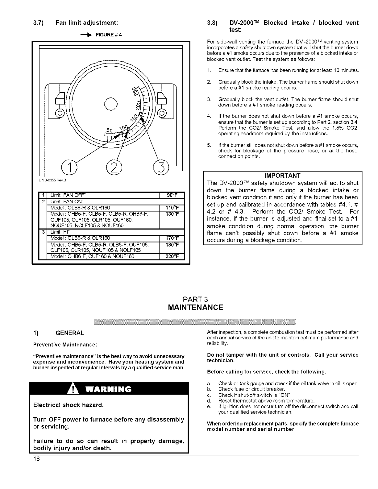
3.7) Fan limit adjustment:
FIGURE#4
DN S_0355 eev.S
1 Limit "FAN OFF" I 90°F
I
2 Limit "FAN ON"
Model: OLB6-R & OLR160 110°F
Model: OHB5-F, OLB5-F, OLB5-R, OHB6-F, 130°F
OUF105, OLF105, OLR105, OUF160,
NOUF105, NOLF105 & NOUF160
3 Limit "HI"
Model: OLB6-R & OLR160 170°F
Model: OHB5-F, OLB5-R, OLB5-F, OUF105, 180°F
OLF105, OLR105, NOUF105 & NOLF105
Model: OHB6-F, OUF160 & NOUF160 220°F
3.8) DV-2000 TM Blocked intake / blocked vent
test:
For side-wall venting the furnace the DV-2000 TM venting system
incorporates a safety shutdown system that will shut the burner down
before a #1 smoke occurs due to the presence of a blocked intake or
blocked vent outlet. Test the system as follows:
1. Ensure that the furnace has been running for at least 10 minutes.
2. Gradually block the intake. The burner flame should shut down
before a #1 smoke reading occurs.
3. Gradually block the vent outlet. The burner flame should shut
down before a #1 smoke reading occurs.
4,
If the burner does not shut down before a #1 smoke occurs,
ensure that the burner is set up according to Part 2, section 3.4.
Perform the CO2/ Smoke Test, and allow the 1.5% CO2
operating headroom required by the instructions.
5. If the burner still does not shut down before a #1 smoke occurs,
check for blockage of the pressure hose, or at the hose
connection points.
IMPORTANT
The DV-2000 TM safety shutdown system will act to shut
down the burner flame during a blocked intake or
blocked vent condition if and only if the burner has been
set up and calibrated in accordance with tables #4.1, #
4.2 or # 4.3. Perform the CO2/ Smoke Test. For
instance, if the burner is adjusted and final-set to a #1
smoke condition during normal operation, the burner
flame can't possibly shut down before a #1 smoke
occurs during a blockage condition.
PART 3
MAINTENANCE
1) GENERAL
Preventive Maintenance:
After inspection, a complete combustion test must be performed after
each annual service of the unit to maintain optimum performance and
reliability.
"Preventive maintenance" is the best way to avoid unnecessary
expense and inconvenience. Have your heating system and
burner inspected at regular intervals by a qualified service man.
Do not tamper with the unit or controls. Call your service
technician.
Before calling for service, check the following.
Electrical shock hazard.
Turn OFF power to furnace before any disassembly
or servicing.
Failure to do so can result in property damage,
bodily injury and/or death.
a. Check oil tank gauge and check if the oil tank valve in oil is open.
b. Check fuse or circuit breaker.
c. Check if shut-off switch is "ON".
d. Reset thermostat above room temperature.
e. If ignition does not occur turn off the disconnect switch and call
your qualified service technician.
When ordering replacement parts, specify the complete furnace
model number and serial number.
18
Page 18
1.1) Heat exchanger:
The entire heat exchanger should be inspected annually for scot
accumulation. If the burner is operating normally there should very
little soot accumulation. If the heat exchanger requires scale removal,
use a wire brush first to loosen the scale and then vacuum the soot
and scale that has fallen into the secondary heat exchanger (radiator)
section. You will find that a 36" long flexible hose attachment will be
helpful to reach into the back of the radiator; a piece of 1/2" flexible
gas connector, or a piece of 1/2" liquid-tight vinyl jacket metallic
electrical conduit works well as a makeshift device.
Cleaning the heat exchanger:
Remove the 4-bolt flange from the front of the furnace to reveal the
clean-out port and check for soot deposits. If there is very little soot in
the radiator section visible from the clean-out port, you will not need to
clean it. However, if you notice scaling in the radiator, you should
remove the scale.
The wrap-around radiator can now be cleaned entirely from the front
inspection port. Also the new furnace has external clean_utpods so
the soot does not fall into the fan compartment during the cleaning
operation.
I IMPORTANT
Do not vacuum the ceramic chambers--they are easily
damaged.
Soot will have collected in the first sections of the heat exchangers
only if the burner was started after the combustion chamber was
flooded with fuel oil, or if the burner has been operating in a severely
fouled condition.
1.2) Refractory fire pot:
Remove the burner and check the fire pot.
IMPORTANT
Use extreme care if cleaning of the pot is required. After
firing, the pot becomes very fragile. Do not use any
commercially available soot remover. This furnace has
a fiber type refractory combustion chamber. Normal
servicing of this unit does not require cleaning of the
combustion chamber.
If the pot is damaged, it must be replaced. A damaged pot could lead
to premature heat exchanger failure. Cracking of the fire pot is normal,
however, replace the pot if the cracks have propagated more than 2/3
the way through the wall thickness. The average wallthickness of the
firepot is 3/4".
Flooding of the fire pot:
Flooding can occur when the oil primary control has been reset a
number of times in a no-heat situation. Each time oil is fired into the
pot and does not ignite, it is absorbed in the pot. Even if the burner is
removed and the pot is felt for wetness, it is difficult to assess the
degree of oil absorption by the pot.
There is only one way to properly service a flooded fire pot, and that is
to change it.
CAUTION
If you observe the red warning light on the burner, push
once ONLY to try and restart. If the burner will not start,
phone your authorised service agent. Do not press the
button again.
Self-aligning firepot:
The appliance primary heat exchanger is comprised of an upper and
lower half. The lower half is essentially a "can" that houses a self-
aligning firepot, the firepot will fit into the bottom half in one orientation
only.
Removing the firepot:
The firepot is seldom replaced, but when it must be replaced one must
simply :
1. Remove the burner.
2. Remove the bumer limit control.
3. Remove the breech plate.
4. Remove the front panel.
5. Remove the brass nuts on the stainless steel heat exchanger
studs.
6. Pry the bottom heat exchanger halves apart using the designated
prying tabs.
7. Remove the bottom heat exchanger half from the furnace cavity
through the front of the furnace.
8. Pull the firepot up and out of the bottom heat exchanger half.
9. Pull the old sealing gasket down off the flange of the upper heat
exchanger half.
10. Scrape off any residual gasket material off the heat exchanger
mating flanges.
Replacing the firepot:
1. Align the slot in the front face of the firepot with the burner tube
sleeve and gently lower the firepot into the bottom heat
exchanger half.
2. Holding the firepot near the perimeter, gently push the firepot all
the way into the bottom heat exchanger half until it seats.
3. Completely wet the gasket with water using a spray pump bottle,
position the tabs over the studs, and push the gasket upward
against the sealing flange of the upper heat exchanger half.
4. Install the brass nuts on the studs by engaging only 2 or 3
threads.
5.
Position the bottom heat exchanger half underneath the upper
heat exchanger half and rotate the bottom half so that the slots in
the bolting tabs engage the stainless steel studs. There is no
further need to hold onto the bottom half as it will now be
suspended on the stud nuts.
6. Push upward on the can and thread the nuts finger-'right asfar as
possible.
7,
Intermittently tighten the stud nuts with a wrench in a sequence
that will pu!l the heat exchanger halves together evenly. Tighten
all nuts to 90 inch-lbs Torque once and then alternately re4_qten
all nuts again to lOg inch-lbs THE RE-TIGHTENING
SEQUENCE IS ABSOLUTELY NECESSARY TO ENSURE A
TIGHT JOINT,
19
Page 19
8,
9.
Re-assemble the front panel, breech plate, limit control and
burner in opposite sequence to their removal.
Follow the instructions for starting the burner for the first time to
cure the firepot and perform combustion checks.
1.3) Drawer assembly:
Remove the drawer assembly. Clean all foreign matter from the
retention head and electrodes. If a Beckett AFG burner has been
installed, the burner will have to be removed to check the retention
head and to check for proper "Z" dimension with the Beckett "T" gauge
supplied with every burner. Check for any sign of oil boiling out of the
nozzle and caulking - the solenoid valve could be leaking (if
applicable).
1.4) Nozzle:
Replace the nozzle with the one specified in table #-4.1to #4.3.
1.5) Oil filter:
Tank filter:
The tank filter should be replaced as required.
Secondary filter:
The lg micron (or less) filter cartridges should be replaced annually.
1.6) Air filters:
Air filters are the disposable types. The disposable filters should be
replaced on at least an annual basis. Dusty conditions, presence of
animal hair etc. may demand much more frequent filter changes. Dirty
filters will impact furnace efficiency and increase oil consumption.
1.7) Motor lubrication:
Do not lubricate the oil burner motor or the direct drive blower motor
as they are permanently lubricated.
1.8) CAS-2B combustion air kit (chimney
venting):
If used, check the CAS-2B combustion air kit for proper operation.
Check to see that the inlet screen is not plugged. Block the air inlet
completely and ensure that a zero smoke reading results. If a zero
smoke reading is not obtained, set up the burner as indicated in table
#4.1, #4.2 or#4.3.
Gradually block off the intake. The CO2 should increase by a
maximum of 0.5 percentage points at the fully blocked condition. If
not, check that the VRV gate is pivoting freely and that the pivot rod is
in a horizontal position. Also, check that the counterweight has been
properly adjusted in accordance with the CAS-2B installation
instructions.
PART 4
INFORMATION
Model:
Date of installation of the furnace :
Service telephones - day :
Dealer's name and address :
Serial number:
Night :
RESULT OF START-UP TEST
Nozzle:
Burner adjustments : Primary air
Fine air
Draw Assembly
Pressure :
Ibpsi
CO 2 : %
Gross stack temperature:
Ambiant temperature:
Chimney draft:
Overfire draft :
Test made by :
Smoke scale :
(Bacharach)
o F
o F
"C.E
" C.E.
2O
Page 20
V]odei :OLB & OLR
F_J_TINGAND PERFORMANCE
--iring rate
_ump pressure (PSIG)
nput (BTU/h)
4eating capacity, chimney installation (BTU/h)
4eating capacity, side-w atl installation (BTUih)
V]inimum - maximum temperature rise
Stack draft, (Chimney), (Side-w all)
Dverfire pressure (chimney), (Side-w atl)
BECKETT BURNER, CHIM NEY INSTALLATION
_ow firing rate baffle
Static disc, model
klozzle (Delavan)
.Combustion air adjustment (shutter / band)
I_IELLO BURNER, CHIM NEY INSTALLATION
klozzle (Delavan)
.Combustion air adjustment (turbulator / damper)
BECKETT BURNER, SIDE-WALL INSTALLATION
klozzle (Detavan)
.Combustion air adjustment (screw / dial) or (dial only)
_IELLO BURNER, SIDE-WALL INSTALLATION
klozzle (Delavan)
.Combustion air adjustment (turbulator / damper)
ELECTRICAL SYSTEM
Jolts - Hertz - Phase
Dperating voltage range
Rated voltage Amp
Vlinimum ampacity for wiring sizing
Vlax. fuse size (Amps)
Sontrot transformer
Ext. control power available, cooling and accessories
BLOWER DATA
3Iow er speed at 0.5" W.C. static pressure
3Iow er speed at 0.25" W.C. static pressure
Vlaximum cooling, speed
Vlaximum cooling, tons @ 0.5" W.C.
Vlotor (HP) / number d speeds
3Iow er wheeI size (in.)
--liter quantity and size
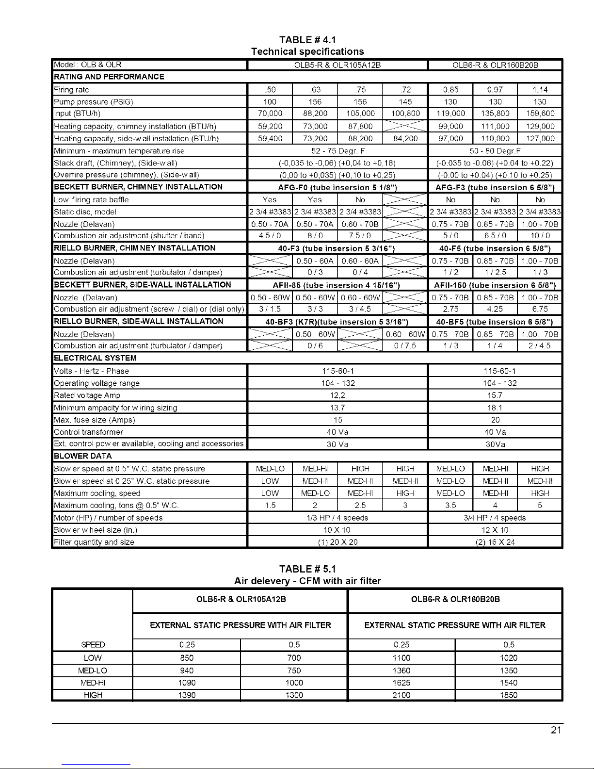
TABLE # 4.1
Technical specifications
OLB5-R & OLR105A!2B
.50
100
70,000
59,200
59,400
.63 .75
156 156
88,200 105,000
73,000 87,800
73,200 88,200
52- 75 Degr. F
.72
145
100,800
84,200
(-0,035 to -0,06) (+0,04 to +0,16)
(0,00 to +0,035)t+0,10 to +0,25)
AFG-F0 Itube msersion 5 1/8")
Yes Yes No
2 3/4 #3382 2 3/4 #3383 2 3/4 #3383
0.50-70A 0.50-70A 0.60-70B
4.5/0 8/0 7.5/0
40-F3 Itube insersion 5 3/16" t
05o-8oAO6O-80A
o/3 o/4
AFII-85 Itube insersion 4 15/16")
0.50-60W 0.50-60W 0.60-60W
3/1.5 3/3 3/4.5
40-BF3 IK7Rtltube ,nsersion 5 3/16")
o.5o-8ow 0.60-8ow
0/6 _ 0/7.5
OLB6-R & OLR160B20B
MED-HI HIGH
MED-HI MED-HI
MED-LO MED-HI
2 2.5
1/3 HP / 4 speeds
10 X 10
(!)20 X20
0.85
130
119,000
99,000
97,000
0.97 1.14
130 130
135,800 159,600
111,000 129,000
110,000 127,000
50-80 Degr.F
(-0.035 to -0.06) (+0.04 to +0.22)
(-0100 to +0.04)(+0.10 to +0.25)
AFG-F3, tube insersion 6 518")
No No No
2 3/4 #3383 2 3/4 #3383 2 3/4 #3383
0.75-70B 0.85-70B 1.00-70B
5/0 6.5/0 10/0
40-F5 Itube insersion 6 5/8" t
0.75-70B 0.85-70B 1.00-70B
1/2 1/2.5 1/3
AFII-150 'tube insersion 6 518")
0.75-70B 0.85-70B 1.00-70B
2.75 4.25 6.75
40-BF5/tube insersion 6 5/8" t
0.75-70B 0.85-70B 1.00-70B
1/3 1/4 2/4.5
115-60-1 115-60-1
104- 132 104- 132
12,2 15.7
13.7 18.!
15 20
40 Va 40 Va
30 Va 30Va
MED-LO HIGH HIGH
LOW MED-HI MED-HI
LOW HIGH HIGH
1.5 3 5
MENLO ME.HI
MENLO ME.HI
MENLO ME.HI
3.5 4
3_ HP/4speeds
12 X 10
t2) 16 X 24
TABLE # 5.1
Air delevery - CFM with air filter
OLB5-R & OLR105A12B OLB6-R & OLR160B20B
EXTERNAL STATIC PRESSURE WITH AIR FILTER EXTERNAL STATIC PRESSURE WITH AIR FILTER
SPEED 0.25 0.5 0.25 0.5
LOW 850 700 1100 1020
MED-LO 940 750 1360 1350
MED-HI 1090 1000 1625 1540
HIGH 1390 1300 2100 1850
21
Page 21
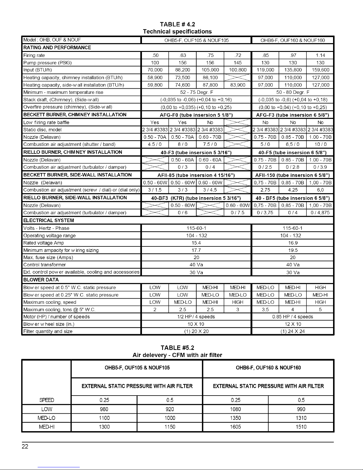
Model : OHB, OUF & NOUF
RATING AND PERFORMANCE
Firing rate
Pump pressure (PSIG)
Input (BTU/h)
Heating capacity, chimney installation (BTU/h)
Heating capacity, side-w all installation (BTU/h)
Minimum - maximum temperature rise
Stack draft, (Chimney), (Side-wall)
Overfire pressure (chimney), (Side-w all)
BECKEFF BURNER, CHIMNEY INSTALLATION
Low firing rate baffle
Static disc, model
Nozzle (Delavan)
Combustion air adjustment (shutter / band)
RIELLO BURNER, CHIM NEY INSTALLATION
Nozzle (Delavan)
Combustion air adjustment (turbulator / damper)
BECKETT BURNER, SIDE-WALL INSTALLATION
Nozzle (Delavan)
Combustion air adjustment (screw / dial) or (dial only)
RIELLO BURNER, SIDE-WALL INSTALLATION
Nozzle (Delavan)
Combustion air adjustment (turbulator / damper)
ELECTRICAL SYSTEM
Volts - Hertz - Phase
Operating voltage range
Rated voltage Amp
Minimum ampacity for w iring sizing
Max. fuse size (Amps)
Control transformer
Ext. control power available, cooling and accessories
BLOWER DATA
Blower speed at 0.5" W.C. static pressure
Blower speed at 0.25" W.C. static pressure
Maximum cooling, speed
Maximum cooling, tons @ 5" W.C.
Motor (HP) / number of speeds
Blow er w heel size (in.)
Filter quantity and size
TABLE # 4.2
Technical specifications
OHB5-F,OUF105 & NOUF105
.5O
100
70,000
58,900
59,800
.63 .75
156 156
88,200 105,000
73,500 86,100
74,600 87,800
52- 75 Degr. F
.72
145
100,800
83,900
(-0,035 to -0,06) (+0,04 to +0,18)
(0,00 to +0,035 (+0,10 to +0,25)
AFG-F0 (tube insersion 5 1/8")
Yes Yes No
2 3/4 #3363 2 3/4 #3363 2 3/4 #3363
0.50-70A 0.50-70A 0.80-70B
4.5/0 8/0 7.5/0
40-F3 (tube insersion 5 3/16")
o.5o-60A0.60-60A
0/3 0/4
AFII-85 (tube insersion 4 15116")
0.50 - 6OW 0.50 - 6OW 0.60 - 6OW
3/1.5 3/3 3/4.5
4O-BF3 (K7R) (tube insersion 5 3/16")
0.50-60W _ 0.60-60W
0/6 0/7.5
OHB6-F, OUF160 & NOUF160
.85
130
119,000
97,000
97,000
.97 1.14
130 130
135,800 159,600
110,000 127,000
110,000 127,000
50-60 Degr. F
(-0,035 to -0,6) (+0,04 to +0,18)
(0,00 to +0,04) (+0,10 to +0,25)
AFG-F3 (tube insersion 6 5/8")
No No No
2 3/4 #3383 2 3/4 #3383 2 3/4 #3383
0.75-70B 0.85-70B 1.O0-70B
5/0 6,5/0 10/0
40-F5 (tube insersion 6 5/8")
0.75-70B 0.85-70B 1.O0-70B
0/2.5 0/2.8 0/3.9
AFII-150 tube insersion 6 5/8")
0,75-70B 0,85-70B 1,00-70B
2,75 4,25 6,0
40 - BF5 tube insersion 6 5/8")
0,75-70B 0,85-70B 1,00-70B
0/3,75 0/4 0/4,675
115-60-1 115-60-1
104- 132 104- 132
15.4 16.9
17.7 19.5
20 20
40 Va 40 Va
30 Va 30 Va
LOW LOW MED-HI MED-HI MED-LO MED-HI
LOW LOW MED-LO MED-LO MED-LO MED-LO
LOW MED-LO MED-HI HIGH MED-LO MED-HI
2 2.5 2.5 3 3.5 4
1/2 HP/4 speeds
10 X 10
(1) 20 X 20
HIGH
MED-HI
HIGH
5
0.85 HP/4 speeds
12 X 10
(1)24X 24
TABLE #5.2
Air delevery - CFM with air filter
OHB5-F,OUF105&NOUF105 OHB6-F,OUF160&NOUF160
EXTERNALSTATICPRESSUREWITHAIRFILTER EXTERNALSTATICPRESSUREWITHAIRFILTER
SPEED 0.25 0.5 0.25 0.5
LOW 960 920 1080 990
MED-LO 1100 1000 1350 1310
MED-H! 1300 1150 1605 1510
22
Page 22

k4odeI : OLB, OLF & NOLF
=_,ATINGAND PERFORMANCE
:iring rate
Dump pressure (PSIG)
nput (BTU/h)
-leating capacity, chimney installation (BTU/h)
-leating capacity, side-w all installation (BTU/h)
k4inimum - maximum temperature rise
Stack draft, (Chimney), (Side-wall)
Dverfire pressure (chimney), (Side-wall)
3ECKETT BURNER, CHIM NEY INSTALLATION
_ow firing rate baffle
Static disc, model
'4ozzIe (DeIavan)
Combustion air adjustment (shutter / band)
=_IELLOBURNER, CHIM NEY INSTALLATION
'4ozzIe (DeIavan)
Combustion air adjustment (turbulator / damper)
3ECKETT BURNER, SIDE-WALL INSTALLATION
'4ozzIe (DeIavan)
Combustion air adjustment (screw / dial)
=_IELLOBURNER, SIDE-WALL INSTALLATION
'4ozzIe (DeIavan)
Combustion air adjustment (turbulator / damper)
-ZLECTRICAL SYSTEM
TABLE # 4.3
Technical specifications
l OLB5-F, OLF!05 & NOLF!05
.50
100
70,000
59,200
59,400
Yes
2 3_#3383
0.50- 70A
4.5/0
.63 .75
156 156
88,200 105,000
73,000 87,800
73,200 88,200
52 - 75 Degr. F
(-0,035 to -0,06) (+0,04 to +0,16)
(0,00 to +0,03511+0,10 to +0,25)
AFG-F0 Itube ineereion 5 I18")
Yes No
2 3/4 #3383 2 3/4 #3383
0.50 - 70A 0.60 - 70B
8/0 7.5/0
40-F3/tube insersion 5 3/16")
0.50 - 60A I 0.60 - 60A
m
0/3 I 0/4
AFII-85/tube insereion 4 15116" 1
0.50 - 60W I 0.60 - 60W
m
3/3 I 3/4.5
0.50 - 60W
3/!.5
40-BF3 (KTR) (tube insersion 5 3/16")
_0.50-60W_0/6
84,200
0.60 - 60W
0/7.5
Volts - Hertz- Phase 115-60-1
3perating voltage range 104 - !32
:_ated voltage Amp 12,2
Viinimum ampacity for wiring sizing 13.7
k4ax. fuse size (Amps) 15
Control transformer 40 Va
Ext. control power available, cooling and accessories 30 Va
3LOWER DATA
LOW HIGH
LOW HIGH
LOW HIGH
1.5 3
3!ow er speed at 0.5" W.C. static pressure
3!ow er speed at 0.25" W.C. static pressure
Viaximum cooling, speed
Viaximum cooling, tons @ 5" W.C.
Viotor (HP) / number of speeds
Blower wheel size lin.)
MED-HI HIGH
MED-HI HIGH
MED-LO MED-HI
2 2.5
1/3 HP / 4 speeds
10X!0
SPEED
LOW
MED-LO
MED-HI
HIGH
TABLE # 5.3
Air delevery - CFM with air filter
OLB5-F, OLFI05 & NOLFI05
EXTERNAL STATIC PRESSURE VVITH AIR FILTER
0.25
84O
96O
1050
1300
0.5
77O
800
98O
1200
23
Page 23

FIGURE# 5.1
Model: OLB5-R059-085-3 & OLR105A12B
21"
19 3/4"
oJ
i
°
32"
©
O
O
--2 13/32 °
19_/4"
41"
17 3/4"
I °
F
• I
T
5" DIAM. FLUE
£
DNS-0571 Rev. B
FIGURE # 5.2
Model: OLB6-R097-130-5 & OLR160B20B
40 _
2 13/32°_
o
c
C
49"
[-,_2 l/a"
23 514" 21 3/#"
I
6" DIAM FLUE
DNS-0573 Rev B
24
Page 24

FIGURE# 5.3
Model: OHB5-F059-085-3 & OUF105A12B
5" DIAM. FLUE
48 _
21"
O
O
O
?
2 _5/52"
18 1/2"
DNS-0568 R_
FIGURE # 5.4
Model: OHB6-F097-130-5 & OUF160B18B
6" DIAM. FLUE_
_25"
o
58
j4"
2 15/32"
25''
5/4"
L_" U
o o
1 8"
DNS-0572 Rev. D
13 3/4"
25
Page 25

FIGURE # 5.5
Model : OLB5-F059-085-3 & OLF105A12B
5" DIAM.
32"
2 15/52"
195/4"
0
0
o
©
2" [_ 17 3/4" _
DNS-0570 Rev. B
FIGURE # 5.6
Model: NOUF105A12B
5" DIAM. FLUE_
DNS-0674 Rev D
21 '_
_19 3/4" _
48"
18 I/2"
15 s/4"
26
Page 26

6" DIAM. FLUE
FIGURE # 5.7
Model: NOUF160B18B
25"
_25 5/4"_
1, l=
L_
58
,_7"
DNS-0675 Rev D
FIGURE # 5.8
Model: NOLF105A12B
• i+
,o _,P [3
1 8 _
5" DIAM.
FLUE
21 _'
L._ L/j
q
32"
55 1/4"
_19 3/4" _
7 5/4"
DNS-0676 Rev C
27
Page 27

--'1_ FIGURE# 6
Wiring diagram, OLB5-R, OLB6-R, OHB5-F, OHB6-F, OLB5-F, OLR105A12B, OLR160B20B,
OUF105A12B, NOUF105A12B, OUF160B18B, NOUF160B18B, OLF105A12B & NOLF105A12B
COOLINg HEATINg
BK
RD
WH
BECKET7 BURNER AFG
BK
RD
WH
BECKETT BURNER AFII
BK _ 1_,530SEI
RD /
WH
RIELLO BURNER R'$O F
I 5508E I
BK BK ]
RD GREY _1
WH WH J _
RIELLO BURNER R¢O BF
_x
[] NEUTRAL HUMIDIFIER TERMINAL
[] NEUTRAL ELECTRONIC AIR CLEANER TERMINAL
[] NEUTRAL TERMINAL
[] ELECTRIC SUPPLY (L1) HUMIDIFIER TERMINAL
[] ELECTRIC SUPPLY (L1) ELECTRIC AIR CLEANER TERMINAL
[] ELECTRIC SUPPLY FROM SWITCH
DNS-0447 Rev. L
28
Page 28

PARTS LIST
Model : OLB5-R059-085-3, Serial # > 264 000
/
/
DETAIL "A"
DNS-0580 Rev. D
@
C>
Complete heat exchanger (combustion chamber included)
2 Top heat exchanger B30465-02
3 Combustion chamber (item 4 included) 330414
4 Gasket, heat exchanger 330517
5 Bottom heat exchanger B30757
6 Hexagonal flange nut 3/8-16NC brass =070001
7 Gasket panel, peep hole B30753
8 Division panel B30488
9 Plenum divider B30478
10 Floor B30472
11 Left side panel ass'y 330509-02
12 Left side panel insutation B30493-04
13 Top rear panel 330511
14 Blower door ass'y (labels included) 330512
15 Air filter drawer 330507
16 20 X 20 X1 paper filter Z04F004
17 Right side panel ass'y 330509-01
18 Right side panel insulation 330493-03
19 Right filter support 330479-01
20 Left filter support 330479-02
21 Gasket, extruded 1/4" X 1/8" x 25' J06L002
22 Front panel ass'y (labels included) 330768-01
23 Front panel insulation 330762
24 Washer 3/8" AA zinc =06F005
25 Hexagonal nut 3/8-16NC brass =07F024
26 Washer, peep hole B30752
27 Hexagonal flange nut 3/8-16NC brass =070001
28A 5" breech plate (chimney application) 330459
28B 3" breech ptate (direct vent application) 330515
29 Gasket, breech plate 330415-02
30 Electrical box cover (without cosmetic) 340085
31 E_ectricat box (box only) 330514
32 Rocker switch SPST (constant blower operation) _07F003
Fan limit control
34 Transformer 120/24 VAC / 40 VA K03040
35 Relay SPDT 24MAC L01H009
36 Terminal strip, 8 positions L05F011
37 BIowerweel 10 X 10 Z01L002
38 Capacitor holder B01024
39 5 MF capacitor L01 t001
40 Blower electrical kit B30057
41 Screw cable tie F11F007
42 Blower support bracket B30473
43 1/3 HP direct drive motor (complete with legs) B01890-01
44 Motor mount ass'y (legs, band and screws) B01888
45A Blower 10 X 10 (housing and wheel) Z011004
45B Blower ass'y (items 38, 39, 43 and 45 included) B01405-03
46 Rubber grommet #19 Z01F006
47 Sealing strip B01291-01
48 Strip B01025-99
49 Gasket, access cover B30415-01
50 Flange plate B30487
51 Hexagonal flange nut 3/8-16NC brass F070001
52 Access cover B30486
53 Rocker switch SPST (main power) L07F016
54 Terminal strip, 8 positions A00336
55 Floor baffle B40481
56 Gasket, access cover B30415-02
57 Gasket, burner B30534
58 Gasket, access cover B30415-02
59 Gasket, sealing plate B30533
60A Peep hole kit K30011
60B Overfire pressure test kit K30012
61 Gasket, glass B30055
62 Glass, neoceram B30041-01
29
Page 29

PARTS LIST
Model : OLB6-R097-130-5, Serial # > 264 000
/
/
\
DNS-0583 Rev. D
_t|li_Ji:t ::i
Complete heat exchanger (combustion chamber included)
2 Top heat exchanger B30596
3 Combustion chamber (item 7 included) B30584
4 Hexagonal flange nut 3/8-16NC brass F070001
5 Gasket panel, peep hole B30753
6 Bottom heat exchanger B30787
• Gasket, heat exchanger B30532
8 Gasket, burner B30534
9 Gasket, heat exchanger B30415 02
10 =ront baffle B30665
1I Rear baffle B30664
12 Division panel B30666
13 #lenum divider B30669
14 =loot baffle B3048 I
15 =loor B30633
16 _eft side panel ass'y B30680 02
17 _eft side panel insulation B30686 02
18 _eft bottom fitter support B30668 02
19 _eft top filter support B30667
20 Strip B 10256 99
21 Gasket, sealing strip B01291 02
22 Slower door ass'y (labels included) B30683
23 &it filter drawer B30678
24 "Fop rear panel B30682
25 Gasket, breech ptate B30589 01
26A B" breech plate (chimney application) B30646
26B 4" breech plate (direct vent application) B30647
27 -{exagonat flange nut 3/8-t6NC brass F070001
28 Gasket, extruded 1/4" X 1/8" x 25' 306L002
29 Right side panel ass'y B30680 01
30 Right side panet insulation B30686 01
31 Right bottom filter support B30668 01
32 Right top filter support B30667
33 =ront panel ass'y (labels included) B30782 01
34 =font panel insulation B30780
=)=!_"(04:_ I;,,itai[el _
#Vasher, peep hole
36 #Vasher 3/8" AA zinc F06F005
37 Hexagonal nut 3/8-16NC brass F07FO24
38 16 X 24 Xl paper filter Z04F007
39 Flange plate B30676
40 Hexagonal flange nut 3/8-16NC brass FO700Ol
41 _,ccess cover B30486
42 Electrical box cover (without cosmetic) B40085
43 Terminal strip, 6 positions LO5F011
44 Rocker switch SPST (main power) L07FO16
45 Rocker switch SPST (constant blower operation) L07FO03
46 Electrical box (box only) B30514
47 Fan limit control R021005
48 Transformer 120/24 VAC / 40 VA KO3O4O
49 Terminal strip, 6 positions Ago336
50 Relay SPDT 24VAC L01HOO9
51 Rubber grommet #19 ZOl F0O6
52 Slower support bracket B01756
53 Slower electrical kit B30530-01
54 Strain release bushing SR-gP-2 L041010
55 Capacitor holder B01024
56 15 MF capacitor L01tO15
57 Slower weet 12 X 10 ZO1LO03
58A Slower 12 X 10 (housing and wheel) ZOll008
58B Slower ass'y (items 55, 56, 58 and 60 included) B01406-06
59 Motor mount ass'y (legs, band and screws) B01889
60 3/4 HP direct drive motor (without legs) L061O04
61A _eep hole kit K30011
61B Overfire pressure test kit K30012
62 Gasket, glass B30055
63 Glass, neoceram B30041-01
3O
Page 30

PARTS LIST
Model : OHB5-F0559-085-3, Serial # > 264 000
DETAIL "A"
@
\
DNS-0579 Rev. E
DETAIL "A"
i = ?Jill :_._N _tI'J I [I]_ _IIl_Jl:l=:
2 Top heat exchanger B30465-01
3 Gasket, heat exchanger B30517
4 .Combustion chamber (item 3 included) B30414
5 Bottom heat exchanger B30757
6 qexagonal flange nut 3/8-16NC brass F070001
7 Gasket panel, peep hole B30753
8 Division panel B30431
9 =loor B30430
10 Baffle B30426
11 Rear panel ass'y B30457
12 Rear paneI insulation B30419
13 Right side panel ass'y B30458-01
14 Right side panel insulation B30418
15 =ront panel ass'y (labels included) B30760-01
16 --rent panel insulation B30761
17 Blower door ass'y (labels included) B30455
18 Door handle Z99F050
19 _eft side panel ass'y B30458-02
20 _eft side panel insulation B30418
2tA 3" breech ptate (chimney application) B30459
21B 3" breech plate (direct vent application) B30515
22 Gasket, breech plate B30415-02
23 qexagonal flange nut 3/8-16NC brass F070001
24 qexagonal nut 3/8-1BNC brass F07F024
25 Masher 3/8" AA zinc F06F005
26 Terminal strip, 6 positions L05F011
Electrical box cover (without cosmetic)
28 ReIay SPDT 24VAC L01H009
29 Transformer 120/24 VAC / 40 VA K03040
30 Fan limit control R021005
31 Rocker switch SPST (constant blower operation) L07F003
32 Electrical box (box only) B30514
33 Blower side rails B30433
34 Blower wee110 X 10 Z01L002
35 1/2 HP direct drive motor (without tegs) L06H004
36 Blower electrical kit B30096
37 Capacitor holder B01024
38 7.5 MF capacitor L01t002
39 Motor mount ass'y (legs, band and screws) B01888
40 Sealing strip B01291-01
41A Blower 10 X 10 (housing and wheel) Z011004
41B Blower ass'y (items 35, 37 38 and 41 included) B01979-01
42 Blower slide B30513
43 Washer, peep hole B30752
44 Rocker switch SPST (main power) L07F016
45 Terminal strip, 6 positions A00336
46 Filter rack ass'y (suppty as an option) B30083
47 20 X 20 Xl paper filter (depends on filter rack size) Z04F004
48 Gasket, burner B30534
49A Peep hole kit K30011
49B Overfire pressure test kit K30012
50 Gasket, glass B30055
51 Glass, neoceram B30041-01
31
Page 31

PARTSLIST
Model : OHB6-F097-130-5, Serial # > 264 000
DETAIL "A
o
0
o
DNS-0582 Rev. D
I|hTil={ =_;=]=l.',[D!;.|I;.ilII[ei
Complet heat exchanger (combustion chamber included)
2 Top heat exchanger B30597
3 Combustion chamber (item 5 included) B30584
4 Hexagonal flange nut 3/8-18NC brass F070001
5 Gasket, heat exchanger B30532
6 Bottom heat exchanger B30787
7 Rear baffle B30619
8 Front baffle B30618
9 Top baffle B30639
10 Division panel B30627
11 Blower slide support B30625
12 Floor B30628
13 24 X 24 X I paper filter (depends on filter rack size) Z04FOl 1
14 Filter rack ass'y (supply as an option) B30656
15 Left side panel ass'y B30653-02
16 Left side panel insulation B30658
17 Rear panel ass'y B30652
18 Rear panel insulation B30659
19 Hexagonal flange nut 3/8-18NC brass F070001
20 Breech plate B30487
21 Gasket, access cover B304t5-0t
22 Gasket, access cover B30415-02
23 Right side panel ass'y B30653-0t
24 Right side panel insulation B30658
25 Gasket panel, peep hole B30753
26 Gasket, burner B30534
27 Gasket, breech plate B30589-0t
28 Front panel ass'y (labels included) B30781-0t
29 Front panel insulation B30779
30 Blower door ass'y (labels included) B30651
31 Door handle Z99FO50
_ [|JiTJl=] =i:Is]=i-"[D!;.ltaII [e J
Washer 3/8" AA zinc
33 Hexagonal nut 3/8-18NC brass F07FO24
34A 6" breech plate (chimney application) B30646
34B 4" breech plate (direct vent application) B30647
35 Hexagonal flange nut 3/8-16NC brass F070001
36 Electrical box (box only) B30514
37 Relay SPDT 24VAC L01H009
38 Transformer 120/24 VAC / 40 VA K03040
39 Fan limit control RO21005
40 Rocker switch SPST (constant blower operation) L07FOO3
41 Electrical box cover (without cosmetic) B40085
42 Washer, peep hole B30752
43 .85 HP direct drive motor (without legs) LO6KOOt
44 Motor mount ass'y (legs, band and screws) B01889
45 Terminal strip, 6 positions L05F011
46 Blower electrical kit B30530
47 Blower weel 12 X 10 ZO1L0O3
48 Sealing strip B01291-0t
49 Blower side rails B30626
50A Blower 12 X 10 (housing and wheel) Z01t008
5OB Blower ass'y (items 43, 5OA, 51 and 52) B02167-0t
51 Capacitor holder B01024
52 10 MF capacitor L011003
53 Rocker switch SPST (main power) L07FO16
54 Terminal strip, 6 positions A00336
55 Gasket, sealing plate B30533
56A Peep hole kit K30011
56B Overfire pressure test kit K30012
57 Gasket, glass B30055
58 Glass, neoceram B30041-01
32
Page 32

PARTS LIST
Model : OLB5-F059-085-3, Serial # > 264 000
DETAIL "A"
DETAIL
@
DNS-0581 Rev. C
_t|J=vJl;t=:
Complet heat exchanger (combustion chamber included) Electrical box cover (without cosmetic)
2 Top heat exchanger 330465-01 34 Electrical box (box only) B30544
3 Combustion chamber (item 4 included) 330414 32 Rocker switch SPST (constant blower operation) LO7F003
4 Gasket, heat exchanger 330517 33 =an limit control R02tOO5
5 Bottom heat exchanger 330757 34 Transformer 120/24 VAC / 40 VA K03040
6 Hexagonal flange nut 3/8-46NC brass =070001 35 Relay SPDT 24VAC LO4 H009
7 Gasket panel, peep hole 330753 36 Terminal strip, 6 positions LOSF041
8 Division panel 330477 37 Blower weet 10 X 10 ZO4LO02
9 Plenum divider 330478 38 Sapacitor holder BO4024
40 Floor 330472 39 5 MF capacitor LO41O01
41 Left side panel ass'y 330504-02 40 Blower electrical kit 330057
42 Left side panel insulation 330493-02 44 Screw cable tie F14 Fog7
43 Top rear panel 330506 42 Blower support bracket 330473
14 Blower door ass'y (labels included) 330512 43 1/3 HP direct drive motor (complete with legs) B01890-01
15 Air filter drawer 330507 44 _otor mount ass'y (legs, band and screws) B01888
16 20 X 20 Xl paper filter 7-04F004 45A BIowerl0XlO(housingandwheel) ZOltOO4
17 Right side panel ass'y 330504-01 45B Blower ass'y (items 38, 39, 43 and 45 included) B01405-g3
48 Right side panel insulation 330493-04 46 Rubber grommet #49 ZO4Fog6
49 Rightflltersupport 330479-04 47 3ealing strip B01291-g4
20 Left filter support 330479-02 48 3trip B30488-g2
21 Front baffle 330483 49 Rocker switch SPST (main power) LO7F046
22 Front panel ass'y (labels included) 330767-01 50 Terminal strip, 6 positions A00336
23 Front panel insulation 330764 51 Basket, breech p_ate 330415-02
24 Washer 3/8"AA zinc =O6F005 52 Basket, burner 330534
25 Hexagonal nut 3/8-46NC brass =O7F024 53 Rear baffle 33049g
26 Washer, peep hole 330752 54 =font baffte 33048g
27 Hexagonal flange nut 3/8-16NC brass =070001 55A 3eep hole kit K30041
28A 5" breech plate (chimney application) 330459 55B Dverfire pressure test kit K30042
283 3" breech plate (direct vent application) 330515 56 Gasket, glass B30055
29 Gasket, breech plate 330445-02 57 Glass, neoceram B3g041-O1
33
Page 33

PARTS LIST
Model : NOUF105A12B Serial # > 264 000
DETAIL "A"
\
DNS-0681Rev. D
1 Somplet heat exchanger (combustion chamber included)
2 Top heat exchanger
3 Sasket, heat exchanger
4 Sombustion chamber (item 3 included)
5 Bottom heat exchanger
6 Hexagonal flange nut 3/8-16NC brass
7 Sasket panel, peep hole
8 Division panel
9 Floor
10 Baffle
11 Rear panel ass'y
12 Rear panel insulation
13 Right side panel ass'y
14 Right side panel insulation
15 Front panel ass'y (labels included)
16 Front panel insulation
17 Blower door ass'y (labels included)
18 Door handle
19 _eft side panel ass'y
20 _eft side panel insulation
21A 5" breech plate (chimney application)
21B 3" breech plate (direct vent application)
22 Gasket, breech plate
23 Hexagonal flange nut 3/8-16NC brass
24 Hexagonal nut 3/8-16NC brass
25 Door handle
26 Terminal strip, 6 positions
27 Electrical box cover (without cosmetic)
28 Relay SPDT 24VAC
B30756-01
B30465-01
B30517
B30414
B30757
F070001
B30753
B30431
B30430
B30426
B30457
B30419
B30458-01
B30418
B30760-01
B30761
B30455
Z99F050
B30458-02
B30418
B30459
B30515
B30415-02
F070001
F07F024
Z99F050
L05F011
B40085
L01HO09
29 Transformer 120/24 VAC / 40 VA _01F009
30 Fan limit control R021005
31 Rocker switch SPST _07FOB3
32 Electrical box (box only) B30514
33 Blower side rails B30433
34 Blower wheel 10 X 10 _Z01L002
35 1/2 HP direct drive motor (complete with legs) _06H004
36 Blower electrical kit B30096
37 Capacitor holder B01024
38 7.5 MF capacitor _011002
39 Motor mount ass'y (legs, band and screws) B01888
40 Sealing strip B01291-01
41A Blower 10 X 10 (housing and wheel) _z01t004
41B Blower ass'y (items 35, 37, 38 and 41A included) B01979-01
42 Blower slide support B30513
43 Washer, peep hole B30752
44 Rocker switch SPST (main power) _07F016
45 Terminal strip, 6 positions _,00336
46 Gasket, burner B30534
47 Front door, vestibule B40293
48 Right panel, vestibule B30725
49 Left panel, vestibule B30726
50 Top panel, vestibule B30723
51 Bottom panel, vestibule B30724
52 Draft regulator _Z06F001
53A Peep hole kit <30011
53B Overfire pressure test kit <30012
54 Gasket, glass B30055
55 Glass, neoceram B30041-01
34
Page 34

PARTSLIST
Model : NOUF160B18B Serial # > 264 000
DETAIL "A"
\
DNS-0680 Rev C
1 Complet heat exchanger (combustion chamber included) B30786-01 33 Hexagonal flange nut 3/8-16NC brass
2 Top heat exchanger B30597 34 Electrical box (box only)
3 Combustion chamber (item 5 included) B30584 35 Relay SPDT 24VAC
4 Hexagonal flange nut 3/8-16NC brass FO700Of 36 Transformer 120/24 VAC / 40 VA
5 Gasket, heat exchanger B30532 37 Fan limit control
6 Bottom heat exchanger B30787 38 Rocker switch SPST (constant blower operation)
7 Gasket panel, peep hole B30619 39 Electrical box cover (without cosmetic)
8 Front baffle B30618 40 Washer, peep hole
9 Top baffle B30639 41 .85 HP direct drive motor (with legs)
10 Division panel B30627 42 Motor mount ass'y (legs, band and screws)
11 Blower slide support B30625 43 Terminal strip, 6 positions
12 Floor B30628 44 Blower electrical kit
13 Left side panel ass'y B30653-O2 45 Blower wheel 12 X 10
14 Left side panel insulation B30658 46 Seating strip
15 Rear panel ass'y B30652 47 Blower side rails
16 Rear panel insulation B30659 48A Blower 12 X 10 (housing and wheel)
17 Hexagonal flange nut 3/8-16NC brass F070001 48B Blower ass'y (items 41, 48A, 49 and 50 included)
18 Breech plate B30487 49 Capacitor holder
19 Gasket, access cover B30415-O1 50 10 MF capacitor
20 Gasket, access cover B30415-O2 51 Rocker switch SPST (main power)
21 Right side panel ass'y B30653-O1 52 Terminal strip, 6 positions
22 Right side panel insulation B30658 53 Gasket, sealing plate
23 Gasket panel, peep hole B30753 54 Front door, vestibule
24 Gasket, burner B30534 55 Right panel, vestibule
25 Gasket, breech plate B30589-O1 56 Left panel, vestibule
26 Front panel ass'y (labets included) B30781-O1 57 Top panel, vestibule
27 Front panel insulation B30779 58 Bottom panel, vestibule
28 Blower door ass'y (labels included) B30651 59 Draft regulator
29 Door handle Z99F050 60A Peep hote kit
30 Washer 3/8" AA zinc F06F005 60B Overfire pressure test kit
31 Hexagonal nut 3/8-16NC brass F07F024 61 Gasket, glass
32A 6" breech plate (chimney application) B30646 62 Glass, neoceram
32B 4" breech plate (direct vent application) B30647
F070001
B30514
L01H009
L01F009
R021005
L07F003
B40085
B30752
LO6K0Ol
B0188g
LO5FOll
B30530
ZO1LO03
B01291-01
B30626
Z01t008
B02167-01
B01024
L011003
LO7FO16
A00336
B30533
B40295
B30632
B30633
B30732
B30728
ZO6F0Ol
K30011
K30012
B30055
B30041-01
35
Page 35

PARTSLIST
Model : NOLF105A12B Serial # > 264 000
DETAIL "A"
%
DETAIL
DNS-0679 Rev C
1 Complet heat exchanger (combustion chamber included) B30756-01 ............3'3
2 Top heat exchanger B30465-01 34
3 Combustion chamber (item 4 included) B30414 35
4 Gasket, heat exchanger B30517 36
5 Bottom heat exchanger B30757 37
6 Hexagonal flange nut 3/8-16NC brass FO7OO01 38
7 Gasket panel, peep hole B30753 39
8 Division panet B30477 40
9 Plenum divider B30478 41
10 Floor B30472 42
11 Left side panel ass'y B30504-02 43
12 Left side panel insulation B30493-02 44A
13 Top rear panel B30506 44B
14 Blower door ass'y (labels included) 830512 45
15 Air filter drawer B30507 46
16 Right side panel ass'y B30504-01 47
17 Right side panel insulation B30493-01 48
18 Right filter support B30479-01 49
19 Left filter support B30479-02 50
20 Front baffle B30483 51
21 Front panel ass'y (labels included) B30767-01 52
22 Front panel insulation B30761 53
23 Door handle Z99F050 54
24 Hexagonal nut 3/8-16NC brass FO7F024 55
25 Washer, peep hole B30752 56
26 Hexagonal flange nut 3/8-16NC brass FO70001 57
27A 5" breech plate (chimney application) B30459 58
27B 3" breech plate (direct vent application) B30515 59
28 Gasket, breech plate B30415-02 60A
29 Electrical box cover (without cosmetic) B40085 60B
30 Electrical box (box only) B30514 61
31 Rocker switch SPST (constant blower operation) L07FO03 62
32 Fan limit control R021O05
Transformer 120/24 VAC / 40 VA
Retay SPDT 24VAC
Terminal strip, 6 positions
Slower weel 10 X 10
2apacitor hotder
MF capacitor
Slower electrical kit
Screw cable tie
Slower support bracket
I/3 HP direct drive motor (with legs)
VIotor mount ass'y (legs, band and screws)
Slower 10 X 10 (housing and wheel)
Slower ass'y (items 37, 38, 42 and 44A included)
Rubber grommet #19
Sealing strip
Strip
Rocker switch SPST (main power)
Terminal strip, 6 positions
Basket, breech plate
Basket, burner
Rear baffle
Wont baffle
=font door, vestibule
Right panel, vestibule
_eft panel, vestibule
Top panel, vestibule
Bottom panel, vestibule
Draft regulator
3eep hole kit
Dverfire pressure test kit
Basket, glass
31ass, neoceram
L01F009
L01H009
L05F011
Z01L002
B01024
L011001
B30057
FffF007
B30473
B01890-01
B01888
Z01iOO4
B01405-03
Z01FO06
B01291-01
B01025-99
L07F016
A00336
B30415-02
B30534
B30490
B30480
B40292
B30729
B30730
B30723
B30724
Z06FO01
K30011
K30012
B30055
B30041-01
36
Page 36

SECTION 1
INSTALLATION
2) RECOMMANDATIONS POUR UNE
INSTALLATION SI_CURITAIRE
1) LIBELLE DE S¢:CURITI_ ET SIGNALISATION
1.1) Danger, Mise en garde et Avertissement:
Comprenez bien la portee des mots suivant d'avertissement : DANGER,
MISE EN GARDE ou AVERTISSEMENT. Ces mots sont associes aux
symboles de securite.
L'installation ou les reparations par du personnel
non qualifie peuvent entrainer des risques pour
vous et les autres. L'installation DOlT 6tre
conforme aux codes Iocaux ou, darts le cas
d'absence de codes Iocaux, elle doit 6tre conforme
aux codes nationaux qui s'appliquent.
Les renseignements contenus dans ce manuel
s'adressent a un technicien qualifi_, experimente
dans ce type de travail, au courant des precautions
prendre, des regles de securite a respecter et
muni des outils appropries ainsi que des
instruments de verification adequats.
Si les instructions de ce manuel ne sont pas
soigneusement suivies, cela peut causer un
mauvais fonctionnement de la fournaise, des
dommages a la propriete, des blessures corporelles
et/ou des pertes de vie.
1.2) Les mots d'avertissement :
Le mot DANGER indique les plus graves dangers, ceux qui
provoqueront des blessures corporelles serieuses ou la mort.
L'expression MISE EN GARDE signifie un danger qui Deut entrafner
des blessures cerporelles ou la mort,
Quant au mot AVERTISSEMENT, il est utilise pour indiquer les
pratiques dangereuses qui Deuvent provoquer des blessures
cerporetles mineures ou des dommages a rappareil ou a la propriet&
1.3) Les mots d'avertissement dans le manuel :
Les mots MISE EN GARDE sont indiques dans Ie manuel de Ia fagon
suivant :
Risque d'incendie
L'appareil doit 6tre installe au niveau. Ne jamais
installer avec une inclinaison vers I'avant.
Si I'appareil est installe dans cette position, I'huile
pourrait couler dans le vestibule et creer un risque
d'incendie, au lieu d'etre achemine vers la chambre
de combustion.
NOTE : IIest de la responsabilite et de robligation du consommateur de
contacter un technicien quatifie pour s'assurer que I'instatlatien est
cenforme aux reglements lecaux et nationaux.
Les mots AVERTISSEMENT sont indiques dans ce manuel de Ia fa£on
suivante
AVERTISSEMENT
a. Cette fournaise N'EST PAS con£ue pour etre installee dans des
maisons mobiles, des caravanes ou des vehicules recreatifs.
b. NE PAS utiliser cotte fournaise comme chauffrette de construction
ou pour chauffer un bStiment en construction.
c. Utiliser uniquement le type d'huile autorise pour cette fournaise
(voir la plaque signaletique sur rappareil). Une surchauffe
provoquera une defectuosite de rechangeur de chaleur et un
fonctionnement dangereux.
d. Verifier les lignes a I'huile pour tout signe d'humidite indiquant une
fuite.
e. S'assurer que la foumaise dispose d'une alimentation adequate
d'air de combustion et de ventilation.
Page 37

f. L'evacuationdesgazdecombustiondolts'effectuerpar
I'evacuateurmuralouparlacheminee.
g. Lespointsenumeresalasection2"Operation"sontessentialsau
fonctionnementnormaletsecuritairedusystemedechauffage.
S'assurerqu'ilsonttousetesbiensuivis.
h. Suivrelesreglementsdescodesd'installationNFPANo.31(Etats-
Unis)etCSAB139(auCanada)oudescodesIocauxpour
I'installationdureservoird'huile.
i. Leserviced'entretienetI'inspectiondoivent6trefaitregulierement
pourunrendementoptimumetsecuritaire.
j. Avantleserviced'entretien,permettrea I'appareiIderefroidir.
ToujourscouperI'alimentationenhuileetI'electriciteavantle
service.CecipreviendralesdechargeseIectriquesetlesbrQlures.
k. Scellerlesconduitesd'alimentationetderetourd'air.
I. Lesystemed'evacuationDOlT6treverifiepours'assurerqu'ilest
deladimensionetdutyperequis.
m. Installerleformatadequatetlebontypedefiltre.
n. L'appareilDOlTetreinstalledetellesortequelescomposantes
eIectriquessoientprotegeesdetoutcontactdirectavecI'eau.
2.1) R_gles de securite :
Votre appareil de chauffage est b_ti pour vous procurer de nombreuses
annees de service en toute securite a la condition qu'il soit installe et
entretenu adequatement. Cependant, un usage abusif ou inadequat
peut raccourcir sa Iongevite et provoquer des risques de danger pour Ie
proprietaire.
a.
La U.S. Consumer Product Safety Commision (Commission
americaine pour la securite des biens de consommation)
recommande que Ies usagers d'appareils de chauffage au gaz se
munissent de detecteurs d'oxyde de carbone. II existe plusieurs
sources d'oxyde de carbone dans un edifice ou une residence:
secheuse a tinge fonctionnant au gaz, cuisiniere au gaz, chauffe
eau, fournaises, foyers atimentes au gaz et biens d'autres encore.
L'oxyde de carbone peut causer des blessures corporelles et
meme entratner Ia mort. Ainsi, afin d'etre averti a emps d'un
niveau d'oxyde de carbone potentiellement dangereux, vous devriez
faire installer dans votre edifice ou residence des detecteurs
d'oxyde de carbone autorises par une agence reconnue sur le plan
national (ex. :Underwriters Laboratories ou International Approval
Services) et les maintenir en bon etat (voir Ia note plus bas).
II existe plusieurs sources possibles de flammes ou de fumee dans
un edifice ou une residence. Les flammes ou la fumee peuvent
causer de serieuses blessures corporelles et meme entratner Ia
mort ou a tout le moins des dommages materiels. Ainsi, afin d'etre
averti a temps d'un debut de feu potentiellement dangereux, vous
devriez vous procurer des extincteurs et faire installer dans votre
edifice ou residence des detecteurs de fumee autorises par une
agence reconnue sur le plan national comme Underwriters
Laboratories et les maintenir en bon etat (voir la note plus bas).
NOTE : Nous ne verifions aucun detecteurs et ne faisons la promotion /
1
d'aucune marque ou type de detecteur.
J
AVERTISSEMENT
S'assurer que I'espace autour de I'entree d'air de
I'evacuateur mural est libre de debris, neige ou glace.
AVERTISSEMENT
Le detecteur de pression DOlT 6tre utilise quand
I'evacuation se fait avec I'evacuateur mural.
AVERTISSEMENT
Ne pas utiliser un nettoyeur pour la suie commercial.
Cet appareil possede une chambre de combustion en
fibre de ceramique. Le service d'entretien normal de
cet appareil n'inclus pas le nettoyage de la chambre de
combustion. E_tretres prudent si des travaux doivent
6tre effectues pres de la chambre de combustion.
2.2) Temperature froide et votre b_timent :
Risque de gel.
Couper I'alimentation en eau.
Si votre appareil demeure ferme durant la saison
froide, les conduites d'eau peuvent geler, eclater et
provoquer des deg_ts d'eau importants.
Votre appareil est muni de dispositifs de securite qui peuvent I'empecher
de fonctionner si Ies detecteurs decelent des conditions anormates
comme, par exempte, des conduites d'evacuation encrassees.
Si le systeme de chauffage est laisse sans surveillance durant Ia saison
froide, prendre les precautions suivantes :
a. Fermer I'entree d'eau principale de la maison ou edifice et vider Ies
conduites d'eau si cela est possible. Ouvrir les robinets aux
endroits requis.
b. Demander a une personne de verifier frequemment durant la saison
froide s'ii y a suffisamment de chaIeur dans la maison ou edifice
pour eviter que les tuyaux gelent. Suggerer a cette personne
d'appeIer une agence de service qualifiee si ceIa est requis.
2.3) Normes d'installation :
Les codes Iocaux et nationaux gouvernant I'installation des appareils
I'huile, des installations electriques et d'evacuation DOIVENT etre
suivies. QueIques un des codes appticabIes sont:
CSA B139 CODE D'INSTALLATION DES
APPAREILS AU MAZOUT
NFPA31 INSTALLATION OF OIL BURNING
EQUIPEMENT
ANSI/NFPA90B WARM AIR HEATING AND AIR
CONDITIONING SYSTEMS
ANSI/NFPA 70 NATIONAL ELECTRICAL CODE
CSA C22.2 NO.3 CODE CANADIEN D'ELECTRICITE
Seulement Ies versions les plus recentes de ces cedes doivent etre
utilisees
Page 38

3) EMPLACEMENT DE LA FOURNAISE
AVERTISSEMENT
Verifier attentivement votre appareil au moment de la
livraison. Des dommages ont put _tre cause durant le
transport et la manipulation. Toutes reclamations pour
dommage ou perte d'accessoire ou de piece dolt _tre
fait a la compagnie de transport.
3.1) Emplacement :
Cependant, ne pas installer rappareil directement sur un tapis ou un
autre matCrieI combustible pouvant emp6cher I'air de circuIer sous le
ptancher.
La foumaise dolt _tre install¢e au niveau pour une operation securitaire
et siIencieuse.
AVERTISSEMENT
NE PAS faire fonctionner I'appareil dans un
environnement corrosif ou contenant du chlore, du
fluor ou autres agents chimiques dommageables.
Referer a la section 1, paragraphe 5.2.
Locatiser I'unit¢ de plus pres possible de la chemin¢e ou de
I'¢vacuateur. Pr6voir suffisamment d'espace pour permettre la
r¢paration et I'entretien.
TABLEAU # 1
Degagements minimums d'installation des materiaux combustible (Installation avec cheminee *)
LOCALISATION APPLICATION OLB6. OHB6- OLR160 _ OUF160 OLB5 - OHB5. OLRt05- OLF105-
- NOUF160 NOLFt05 -OUFt05- NOUF105
Fournaise
C6t¢ Foumaise ou pt¢num
Arriere Fournaise
Dessus Foumaise ou pt¢num
Dessous Foumaise - plancher combustible
Devant Fournaise
*Voir Section ! partie 2.3, D6gagement minimum du systeme d'evacuation murale
1" 1 I_
1" 1"
18" 1"
2" 1"
0" 0"
24" 24"
4) €:VACUATION
L'appareil fonctionnera a!ors avec un tirage positif au-dessus de la
flamme et darts la chemin¢e.
4.1) General :
Ces appareils de chauffage central peuvent 6tre 6vacu¢s de ptusieurs
fagons:
E_vacuation par une chemin_e :
Lorsqu'insta!l¢ avec un brOleur Beckett AFG ou Riello 40-F, I'appareil
peut etre 6vacu¢ par une chemin¢e, avec ou sans clapet barometrique.
L'appareil va fonctionner avec un tirage negatif au-dessus de Ia flamme
et darts la cheminee.
Risque d'empoisonnement par oxyde de carbone.
Ne jamais faire I'evacuation d'un autre appareil
combustion avec un evacuateur mural.
II pourrait en resulter I'asphyxie ou/et la mort des
occupants.
Risque d'empoisonnement par oxyde de carbone,
de feu et d'explosion.
Lire et suivre attentivement les instructions dans la
partie suivante.
Si cette fournaise ou d'autres appareils ne sont pas
adequatement evacues, cela peut provoquer des
dommages a la propriete, des blessures corporelles
et/ou des pertes de vie.
E_vacuation murale :
Lorsqu'instatI¢ avec les brQleurs Beckett AFII ou Riello 40-BF munis de
contr61es de pr¢ et post purge integres, I'appareil peut _tre Cvacue de
fagon murale avec une efficacit¢ maximale et ce, sans evacuateur.
4.2) I_vacuation par cheminee :
Lorsque les appareils de chauffage central a I'huile sont Cvacues par une
cheminCe, ils sent certifies pour fonctionner avec des events de type
"L", de type "A" et des cheminCes avec un conduit en tulle, ou en tulle
avec un rev_tement metallique; IIs peuvent _tre Cvacu¢s avec ou sans
clapet de tirage baromCtrique. L'unit¢ n'est toutefois pas certifiCe pour
fonctionner sans clapet barom¢trique si eIle est co-¢vacuee avec un
autre appareiI fonctionnant a I'huiIe, comme un chauffeeau par exemple.
Avec clapet :
L'appareil peut _tre installe avec une chemin¢e de dimensions et de
temperatures adequates, telles que specifi_es darts le code
d'installation CSA B139. L'extrait correspondant du code se trouve darts
Ia Section Dimensions du tuyau de fumee.
Page 39

Sans clapet :
Pour compenser ies rJsques plus eleves de condensation dans 1'event,
la cheminee dolt etre munie d'un revetement. De plus, Ie revetement
dolt etre isole selon les specifications de son fabricant.
Raccords d'event:
Pour ies installations sans clapet, les raccords d'event devraient etre
aussi courts que possible et con(2us soit pour mur double ou pour mur
simple avec 1" d'isolant. La pente devrait augmenter d'au minimum 1/4"
par pied entre I'appareil de chauffage central et la cheminee. Les
raccords fabriques sur place devraient avoir un minimum de 28 gauges.
Les joints doivent etre scelles mecaniquement pour qu'aucun produit de
combustion ne puisse s'echapper par les joints.
Dimensions du tuyau de fumee :
Le tableau suivant est extrait du code d'instaltation CSA B!39. Cet
extrait indique a la fois le diametre permis pour le tuyau de fumee et la
temperature minimum a la base d'une cheminee circulaire dent la
resistance thermique est inferieure 8 R6 (6 p_,,h ,,°F / BTU).
Risque d'empoisonnement par oxyde de carbone.
Ne jamais installer un volet manuel sur le tuyau
d'evacuation. Cependant, un volet motoris_
fonctionnement automatique approuve par une
agence certifiee peut _tre installe, si desir& Suivre
les instructions d'installation fournies avec le volet
motoris& Lire et suivre toutes les instructions
contenues dans cette section.
Si cette fournaise ou d'autres appareils ne sont pas
adequatement evacues, cela peut provoquer des
dommages a la propriete, des blessures corporelles
et/ou des pertes de vie.
AVERTISSEMENT
Si I'appareil de chauffage central (installe avec une
cheminee) est co-evacue avec d'autres appareils
combustion, tels qu'un chauffe-eau, il faudra aussi
etudier les materiaux d'evacuation permis (i.e. event
de type L etc.) avec ces appareils.
Lorsqu'un nouvel appareil, brOleur ou cheminee est instalte, la
dimension des events de Ia cheminee et Ia temperature maximale de la
fumee (mesuree a la virole de la cheminee, apres que i'appareil a
fonctionne 5 minutes avec le clapet barometrique en position fermee)
doivent se conformer aux donnees indiquees darts le tableau # 2.
TABLEAU # 2
Capacite d'admission totale de tous les Diametre interne du tuyau A Temperature de base minimum (°F)
appareils connectes fumee Ipo.I selon la hauteur de la cheminee Ipil
kW kBTU!h USGPH ' Mini " Max. ' t 1 ' 20 ' 28 ' 36
2! 70 0.50 3 5 300 400 535 725
27 91 0.65 3 5 275 340 430 535
3! 105 0.75 4 5 260 320 380 475
36 119 0.85 4 5 250 300 355 430
41 140 lJ00 4 6 225 300 365 430
51 175 lJ25 4 6 240 275 320 365
I NOTE: Vateurs de resistance thermique pour des cheminees typiques:
R2(2 pi2 ,h ,°F / BTU) :
R3(3 pi2 ,h ,°F / BTU) :
R6(6 pi2 ,h ,°F / BTU) :
cheminee en magonnerie avec conduit
en ardoise et un event de type A
cheminee en magonnerie avec conduit
en ardoise et un revetement
cheminee en ma£onnerie avec conduit
en ardoise ou en metat, et avec un
isolant R4.5 (4.5 pi2oh °°F / BTU) entre
la ma£onnerie et le revetement
(ex: 2 po. de mica expanse ou un
panneau de 1 3/8 po. de fibres de verre
agglomerees a haute densite)
Utilisation du tableau # 2
Supposons qu'un appareil de chauffage central avec un gicieur 0.60
USGPH dolt etre raccord6 a une cheminee en ma9onnerie de 20 pi. de
haut avec un conduit en ardoise. La resistance thermique de ce type de
cheminee est R2, donc inferieure a R6. L'allure de combuston reelle
145 psig est doric ! .2 x .60 = .72. Par
consequent, les donnees du tableau qui s'appliquent sont Ies suivantes:
Le diametre interieur minimum permis est de 4 po.
Le diametre interieur maximum permis est de 5 po.
I La temperature de base minimum devrait etre d'environ 320°F.
4.3) Syst_me d'evacuation murale
DV-200OTM :
L'evacuation murale des appareils de chauffage central peut se faire
sans evacuateur mecanique, grace a la capacite de pression statique
elevee des brQleurs a I'huile Becke[t AFI! et Riello 40-BF, L'air de
combustion exterieur dolt _tre directement branch_ au brQleur.
Autrement, le systeme d'_vacuation mural DV-2000 TM ne
fonctionnera pas.
Les caracteristiques du systeme DV-2000 sont Ies suivantes:
a. Certifie pour utiliser Ies materiaux suivant pour le tuyau d'entree
d'air: PVC DWV cedule 40, ABS DWV cedule 40 et tuyau pour
fosse septique ASTM 2729.
b. Une ouverture minimum de 6" de diametre est requise darts lemur
et I'evacuateur mural est congu pour etre instaile entre des solives
de2x8.
c. Contient un systeme d'arret de securite dans i'eventualite d'un
blocage complet ou partiel de Ia sortie des gaz ou de I'entree d'air.
Ainsi, le brQleur arr_te avant que I'indice de fumee soit de 1.
Page 40

d. L'entreed'airetlasortiesontaccessiblepourlenettoyage.
IIy a troiscomposantesprincipalesdanslesystemeDV-2000;
I'ensembled'evacuateurmuralVTK,letuyaud'evacuationisoleIFVetle
tuyaud'entreed'airenPVCouABS3"dediametre.
L'evacuateur mural - DV-2000 TM
L'evacuateur mural permet I'instaIlation sur un mur d'une epaisseur
maximum de 14". L'ensembIe contient les items suivants :
1 Evacuateur mural
2 Coltet d'etancheite
1 Bride d'evacuation
2 Bande scellante
1 Plaque mural interieur
1 Detecteur de pression avec conduit
6 Vis autopergante en acier inoxydable
2 Terminaux isoles a racoord rapide
3 Vis en acier inoxydabte
Conduits flexibles isoles - DV-2000 TM
Les conduits flexibles disponibles en trois Iongueurs, ModeIe No IFV3-
15, IFV3-23 et IFV3-30 (ou IFV4-15, IFV4-23 et IFV4-30 pour 160
modeles) correspondent aux Iongueurs de 15', 23' et 30' de tuyau. La
construction du conduit est de type coaxia! et comprend un tuyau flexible
interieur en acier inoxydable de 4" de diametre entoure d'une isolation
qui est elle-meme entouree du tuyau flexible exterieur en aluminium de
6" de diametre. II est interdit de joindre deux bouts de conduit, Les
Iongueurs minimum et maximum sont :
5 pieds minimums 30 pieds maximums
Risque d'empoisonnement par oxyde de carbone.
M_me si le conduit flexible est isole, il ne peut
passer dans un espace non isole (pas chauffe).
Ceci causerait de la condensation residuelle qui
peut, a long terme, perforer le conduit en acier
inoxydable.
TABLEAU # 3.1
De_lagement minimum du systeme d'evacuation murale (Modeles OLB5, OH B5, OLR105, OUF105, OLF105, NOUF105 et NOLF105 !
SECTION DU CONDUIT D'IeVACUATION ' CANADA ETATS-UNIS
Conduit d'evacuation, de Ia sortie de la foumaise iusqu'a un pied de la sortie de Iafournaise* 1/4" 3"
Conduit d'evacuation, iusqu'a I'evacuateur mural* ZERO 3"
Evacuateur mural ZERO ZERO
*Le conduit ne dolt pas passer dans une enceinte fermee.
TABLEAU # 3.2
De_a_lement minimum du systeme d'evacuation murale IModeles OHB6, OLB6, OLR160, OUF160, NOU1601
is c_ouco.ou, o,0 I
Conduit d'evacuation, iusqu'a I'evacuateur mural* 3" 3"
Evacuateur mural ZERO ZERO
* Le conduit ne dolt pas passer dans un enceinte ferme.
Considerations concernant I'installation - DV-2000 TM
Selectionner I'emptacement de la sortie de I'evacuateur mural en
respectant les codes Iocaux et nationaux. Les exigences suivantes
doivent 6tre considerees comme minimates et peuvent etre remplac_es
par un code Iocat ou national plus strict.
Un event ne dolt pas se terminer :
a. Directement au-dessus d'un trottoir ou d'une entree pavee, situes
entre deux b_timents et desservant cos deux b_timents ;
b. ,g,moins de 7 pieds au-dessus de toute entree pavee;
c. ,g, moins de 6 pieds (au Canada) ou 4 pieds (aux Etats-Unis) d'une
porte ou d'une fenetre qui s'ouvre ou d'une ouverture destinee
I'approvisionnement en air d'un edifice;
d. ,g, moins de 6 pieds (au Canada) ou 1 pied (aux Etats-Unis) du
soffit du toit de la structure;
e. Au dessus d'un compteur de gaz ou d'un regulateur, ou a moins de
3 pieds du centre vertical du regulateur ;
f. ,g, moins de 6 pieds de toute sortie d'event d'un regulateur de gaz
ou a moins de 3 pieds de I'event d'un reservoir d'huiIe ou de I'entree
pour le remplissage de I'huile ;
g. ,g,moins d'un pied au-dessus du niveau du sol ;
h. ,g,6 pieds de toute entree d'air pour la combustion;
i. ,g,moins de 6 pieds de la limite du terrain ;
j. Sous une veranda, un porche ou un patio ;
k. Avec les gaz de combustion diriges vers des materiaux
combustibles ou vers toute ouverture des edifices avoisinants,
situes a moins de 6 pieds;
I. ,g,moins de 3 pieds du coin interieur d'une structure en L ;
m. Avec Ie dessous de I'ouverture de I'extremite de I'event situee
moins d'un pied au-dessus de toutes surfaces pouvant porter de la
glace, de la neige ou des debris ;
n. Avec les gaz de combustion diriges vers de la magonnerie de
brique, un recouvrement ou autre construction qui pourrait etre
endommagee par Ia chaleur ou la condensation des gaz de
combustion.
AVERTISSEMENT
La majorite des codes ont une clause m@e enongant
que les produits de combustion ne doivent penetrer
dans I'habitation sous aucunes circonstances et ce,
m_me si toutes les autres exigences du code
concernant la construction et I'emplacement ont ete
respectees. L'installateur a la responsabilite ultime de
prendre toutes les mesures necessaires pour s'assurer
que les produits de combustion ne peuvent pas
s'introduire dans les espaces habites.
Page 41

FIGURE # 1.1
IEUR
FIGURE # 1.2
LE TUYAU
R
FIGURE # 1.3 FIGURE # 1.4
FIGURE # 1.5 FIGURE # 1.6
Page 42

FIGURE# 1.7 FIGURE# 1.8
FIGURE# 1.9 FIGURE# 1.10
FIGURE# 1.11
Page 43

FIGURE # 1.12
FIGURE # 1.13 FIGURE # 1.14
10
Page 44

Installation du systeme d'evacuation mural - DV-2O0OTM
Danger de coupures.
Toujours porter des gants et des lunettes
protectrices Iors de I'installation.
Couper le conduit flexible peut laisser des parties
coupantes sur le tuyau et celles-ci peuvent blesser
I'installateur qui n'y porte pas attention.
Branchement b lasortie de la fournaise - DV-20OOTM
Enlever la bride qui est sur Ia fournaise en enlevant les ¢crous
en Iaiton.
2.
Determiner dans quelle direction le conduit ira. Ensuite,
installer la bride fournit avec [ensemble d'evacuation directe
VTK pour que le conduit d'acoes de mesure de la pression
soit accessible une fois I'installation terminee. Cependant, ne
pas installer ce conduit pointant vers Ie bas. Serrer Ies ecrous
en Iaiton.
3.
Enlever le tuyau flexible de diametre un peu plus eleve ("tuyau
visse") qui est au-dessus I'event flexible en le "devissant".
4.
Couper un bout de 12 pouces de Iongueur du "tuyau visse"
(voir fig. # 1.!). Une fois que toute Ia circonference est
coupee, coupe Ie materiel qui reste avec des ciseaux a metal
(voir fig. # 1 .!).
5.
Avec des ciseaux a metal, enlever 5" au tuyau exterieur en
aIuminium (voir fig # 1.1). Faire bien attention que la coupure
soit droite et sans bavure car le "tuyau visse" dolt aller a cet
endroit.
6.
Visser le "tuyau visse" de 12 pouces par-dessus le tuyau
d'aluminium (voir fig. # 1.3) jusqu'a une distance d'environ !0
pouces de I'extremite de I'event.
7.
Couper Ie tuyau de 3 pouces en acier inoxydable sur environ 3
pouces. ,g,ce moment environ 3 pouces de I'isoIation excedera
Ie tuyau en acier inoxydable (voir fig. # 1.4)
8.
Pousser aussi loin que possible le tuyau en acier inoxydable
sur la bride de la fournaise (voir fig. # 1.5). Le fixer a la sortie
avec trois vis autopergantes #8x1/2" fournis (voir fig. # 1.6) et
dispose a egale distance autour du tuyau. De plus, les vi_
doivent etre de 3/8" a 5t8" de rextremite du tuyau et visser
dans un creux du tuyau. Ceci assurera une etancheite parfaite
Iors des prochaines operations.
9.
Appliquer Ie scellant fourni, a I'extremite du tuyau en acier
inoxydable (voir fig. # 1.7). La partie centrale du scellant dolt
etre vis-_,vis I'extremite du tuyau en acier inoxydable. Faire le
tour complet du tuyau plus _½" (double epaisseur a oet endroit).
Recouvrir les t_tes de vis autopergantes de I'etape precedente
avec le scellant.
10.
Verifier que les collets en acier inoxydabIe fournis sont bien dans
Ia bonne position pour un serrage ad¢quat (voir fig. # 1.8).
Positionner le collet de serrage vis-_,vis Ie scellant et serrer
suffisamment pour qu'il s'ecrase (voir fig. # 1.9). Ce joint est
permanent et Ie nettoyage dolt se faire en enlevant les quatre
ecrous qui fixe la bride a rappareil.
1!.
Pousser I'isolation vers la bride. Deplacer Ie "tuyau visse" vers
Ia bride le plus loin possible. L'autre extremite du "tuyau visse"
dolt 6tre cacher avec du ruban d'aluminium pour enlever Ies
bavures et eviter Ies coupures. (voir fig. # !. !0)
Branchement b I'_vacuateurmural - DV-2000 TM
Couper une Iongueur de 12" du "tuyau visse" sembIable a ceIle
coupee a I'etape precedante.
Effectuer les m_mes etapes que precedemment (pour la
partie de I'event sur I'appareil) pour finalement obtenir ce qui
est montre aux figures # ! .11 et 1.12.
Donner a I'event I'angle voulu pour sortir vers I'exterieur
I'endroit voulu.
Installation de I'evacuateur au mur - DV-2O0OTM
Faire un trou de 6" de diametre dans lemur en considerant les
restrictions des sections precedentes.
Fixer la plaque murate sur lemur interieur avec des vis
appropriees fournis par I'installateur. Prendre note que le
support du detecteur de pression dolt etre enlever pour
atteindre la vis superieure droite de la plaque murale. Installer
Ia plaque murale pour que la partie superieure du trou darts Ia
plaque soit a 1/8" de la partie superieure du trou dans lemur.
Ceci assurera I'incIinaison requise de I'evacuateur de
rinterieur vers rexterieur.
Enlever les deux vis qui flxent le cSne de I'evacuateur et
renlever.
Enlever les deux vis qui flxent le stabiIisateur de I'evacuateur
et I'enlever.
Passer la partie principale de l'evacuateur a travers Iemur et la
Iaisser depasser de 2" du cote exterieur.
6. Installer le stabiIisateur de I'evacuateur (voir fig. # !.13).
Pour les murs de ciment, il est possible que le stabilisateur ne
couvre pas toutes les irregularites du trou dans lemur. II est
possible d'instatIer une plaque murale en acier inoxydable
(304,316 ou 316L) foumi par I'installateur.
AppIiquer un scellant (silicone) a I'endroit ou Ie stabilisateur
rencontre la partie principate de I'evacuateur (tuyau).
Appliquer un scellant adhesif sur la partie arriere du
stabilisateur et pousser fermement Ie stabilisateur contre le
mur. S'assurer que le d_tecteur de pression est situ_ sur
le dessus, en position horizontale.
10.
Avec les 3 vis en acier inoxydable de 2" foumis, fixer le tout
en place mais en poussant vers le bas pour assurer
I'inclinaison requise. Ne pas trop serrer les vis pour ne pas
deformer le stabiIisateur. Les vis ne sont pas requises pour
Ies murs de ciment.
1!.
Serrer le collet de la plaque murale interieure pour fixer le tout
en place.
12.
Appliquer suffisamment de scellant autour du stabiIisateur
pour avoir un joint etanche (voir fig. # ! .14).
13. Installer Ie c6ne avec les 2 vis.
14.
L'inclinaison de I'evacuateur dolt _tre de 1/4" a 1/2" pour que
Ie drainage (de I'interieur vers I'exterieur) soit efficace darts
I'evacuateur.
11
Page 45

Branchement du tuyau d'entree d'air sur I'_vacuateur - DV-2000 TM
R_ferer a la section 3.2, Air de Combustion exterieur- Evacuateur mural,
DV-2000 TM.
5) APPROVISIONNEMENT EN AIR DE
COMBUSTION
Risque d'empoisonnement par oxyde de carbone.
Referer aux codes d'installation des appareils au
mazout ANSI/NFPA (aux letats-Unis) ou CSA (au
Canada) et aux codes Iocaux pour fournir I'air de
combustion et de ventilation.
Une quantite insuffisante d'air de combustion peut
occasionner une flamme malpropre, des odeurs
dans la maison, le refoulement des appareils de
combustion et peut entrainer des nausees ou
I'asphyxie ou/et la mort des occupants.
5.1) Generalites :
Les appareiIs de chauffage central necessitent un approvisionnement
adequat en air de combustion. II est frequent de consid¢rer que les
vieiIles maisons comportent suffisamment d'infiltrations d'air pour
combler les besoins en air de combustion de I'appareil de chauffage
central. Toutefois, les projets d'ameliorations telles les nouvelles pores
et fenetres et le calfeutrage ont dramatiquement reduit Ie volume des
infiltrations d'air penetrant dans les maisons.
Les systemes d'echappement d'air de la maison sont frequents. Les
ventilateurs de cuisine et de salles de bain, les secheuses electriques et
Ies chauffe-eau tendent tous a creer une pression negative dans la
maison. Si une pression negative se produit dans la maison, la
cheminee devient de moins en moins efficace et peut faciIement refouIer
I'air.
Les systemes de recuperation de chaleur gagnent en popularit& Ces
systemes ne sont pas congus pour approvisionner de I'air de
combustion. Si le systeme de recuperation de chaIeur n'est pas bien
equilibre, une forte pression negative peut se produire.
5.2) Air de Combustion contamine :
L'installation dans certain environnement ou b_timent peut augmenter les
risques d'exposition aux agents chimiques ou halogene qui peuvent
endommager I'unit& Celles-ci requierent un apport d'air de combustion
exterieur. Les environnements ou bStiments suivant peuvent contenir ou
etre expose au substance decrite plus bas. L'insta!lation dolt etre
evaluee attentivement pour verifier si I'air de combustion dolt provenir de
rexterieur.
a. BStiments commerciaux
b. BStiments avec piscines interieures
c. Appareil installe a proximite de zones d'entreposage d'agent
chimique
Exposition aces agents chimiques:
a. Solution pour cheveux
12
b. Cires et nettoyant a base de chore
c. Agent chimique pour piscine a base de chIore
d. Agent chimique adoucisseur d'eau
e. Sets ou agent chimique pour le deglagage
f. TetrachIorine de carbone
g. FIuides frigorigenes ha!ogenes
h. Solvant de nettoyage (perchloroethylene)
i. Encre pour I'impression, diluant a peinture, vernis, etc.
j. Acide chlorhydrique
k. Colles 8 base de solvant
I. Adoucisseur antistatique pour secheuse alinge
m. Acide de nettoyage pour ma9onnerie
5.3) Approvisionnement en air de combustion
exterieur :
Trois types de brQleurs sont possible pour prendre I'air de combustion
I'exterieur et racheminer directement, par conduit, au brQleur: le brQleur
Beckett AFII et Riello 40-BF pour une evacuation murale et le Beckett
AFG pour une evacuation par la cheminee. Le brQleur Riello 40-F ne
peut pas etre utiIise de cette fa(2on.
AVERTISSEMENT
L'utilisation de I'air de combustion achemine de
I'exterieur est obligatoire avec les installations
evacuation murale. Ce systeme fonctionne selon le
principe de la combustion scelle et il ne fonctionnera
pas adequatement si un conduit acheminant I'air de
I'exterieur n'est pas connecte directement au brQleur de
I'appareil.
Air de combustion exterieur- evacuation par cheminee
Les ensembles suivants sent homologues pour etre utilises avec
I'appareil. Les ensembles de composantes offrent un important dispositif
de securite, la soupape casse-vide. En fonctionnement normal, le
brQleur s'approvisionne en air a I'exterieur. Par contre, si la sortie
d'approvisionnement est partiellement ou completement bloquee par de
Ia glace, de la neige, etc., la soupape casse-vide s'ouvre pour laisser
passer une partie de rair de rhabitation dans Ie brOleur, maintenant ainsi
une combustion adequate. Une fois le blocage enleve, la soupape
casse-vide se referme et Ie brQIeur prend a nouveau son air entierement
de I'exterieur.
CAS-2B Cet ensemble inclut rextremite d'approvisionnement, la
soupape casse-vide et le raccord pour rair du brOleur AFG. II peut etre
utilise avec un conduit en acier galvanise rigide ou en aluminium flexible
de 4". II est recommande d'isoler Ia section qui part de I'entree d'air
jusqu'a une distance de 5 pieds du brQleur pour eviter Ia condensation
I'exterieur du tuyau.
AVERTISSEMENT
L'ensemble CAS-2B ne convertit pas I'appareil de
chauffage central en un systeme a evacuation directe.
La structure du b_timent dolt fournir suffisamment d'air
de combustion a la soupape casse-vide puisque le
brQleur prendra son air de combustion de la soupape
casse-vide si I'entree d'approvisionnement est bloquee.
Par consequent, suivre les codes d'installation pour une
evacuation avec cheminee.
CAD-1 L'ensemble des conduites d'air inclut 25 pieds de
conduites a air isolees de type UL/ULC classe ! et deux colliers de
serrage de 4" en acier. La conduite est constituee d'un noyau en
atuminium ondule entoure d'un isolant en fibre de verre Iui-meme
Page 46

couvertd'uncoupe-vapeurenvinyle.LaIongueurmax!maledeconduite
permiseestde25pieds.
Desinstructionsdetailleessontfoumiesavecles ensembles
d'approvisionnementenairdecombustionexterieur.
Air de combustion exterieur- evacuateur mural DV-2000 TM
Le systeme d'evacuation DV-2000 est un systeme de combustion sceIle
ayant pour effet d'isoler Ia fournaise par rapport a I'interieur du b&timent.
Le brQleur n'est donc pas affecte par une variation de la press!on dans le
bStiment et est ideal pour etre utiIise dans des constructions tres
etanches.
Le systeme d'evacuation DV-2000 requiere des pieces additionnelles qui
ne sont pas incluses dans [ensemble. Elles do!vent etre de 3" de
diametre et constituees d'un des materiaux suivant: PVC, PVC-SWV,
SDR-26, SDR-21, ABS ou tuyau de fausse septique. Un scellant
adequat pour le materiel dolt etre utilise. De plus, les procedures
d'instaIlation, les conduits et les raccords do!vent etre conformes aux
normes ANSI/ASTM suivantes:
PVC ASTM D-1785
SDR26, SDR21 ASTM D-2241
Tuyau de fausse septique ASTM D-2729
PVC-DWV ASTM D-2665
Adhesif PVC ASTM D-2564
ABS tuyau et raccord ASTM D-2235
Procedure de collage des joints ASTM D-2855
Autres pieces requises (pas incluses dans I'ensemble VTK)
a. Coudes de 3 po. de diametre
b. Tuyau de 3 po. de diametre
c. Coude 90° de 3" (femelle-femelle) pour I'evacuateur
d. Reducteur 3 po. femelle a 2 po. femelle (brgleur Riello BF
seulement)
e. Coude 90 ° 2 po. de diametre (street type) femelle-m_Ie (bruleur
Riello BF seulement)
f. Adapteur 3 po. femelle-femelle en PVC ou ABS (conduit de fausse
septique exclu) (brOleur Beckett AFII-85 seulement)
g. Deux raccords de transition entre I'ABS ou PVC et Ie tuyau fausse
septique ASTM D-2729 (si applicable)
Si le PVC est utilise avec I'ABS, utiliser un scellant qui est approuve
pour les deux types de plastique.
Longueurde conduit-DV-2O0O TM
Le systeme d'evacuation mural DV-2000 a ete approuve pour 6tre utilise
avec une Iongueur equivalante maximum de 120 pieds de conduit 3" de
diametre. Un coude de 90 ° est equivalant a une Iongueur de 10 pieds et
un code de 45 ° a une Iongueur de 5 pieds.
Par exempte:
1
2
3
2
1
1
5' de Iongueur = 5 pieds equivalants
10' de Iongueur = 20 pieds equivalants
Coude 90 ° = 30 pieds equivalants
Coude 45 ° = 10 pieds equivalants
Coude 90 ° = 10 pieds equivalants
Coude 90 ° = 10 pieds equivalants
total = 85 pieds equivatant, ce qui
est acceptable.
Installation du tuyau d'entree d'air - DV-2000 TM
Commencer par installer les conduits au brC_leur.Si le vestibule optionnel
est utilise, enlever les debouchures (knock-out) appropries sur les
panneaux de cote du vestibule. La plus basse debouchure sur le
panneau de droite est utiIise pour le brgleur Beckett AFII. Les plus
hautes debouchures sur les panneaux de gauche et de droite sont
utilises pour Ie brOIeur Riello 40-BF.
Brt_leur Beckett AFII
Enlever le couvert de I'entree d'air du brgleur en enlevant les trois vis qui
le tiennent en place. Appliquer du sceIlant (silicone) sur un adapteur de 3
" et inserer la partie avec le sceIlant dans I'ouverture du brgIeur.
Sol!differ avec 3 visa metal autopergante.
Brt_leur Riello 4O-BF
Inserer la partie femeIle d'un coude 90 ° de 2 " de diametre dans
I'ouverture sur le dessus du brGleur prevue a cette fin. Solid!fie, avec 3
vis a metal autopergante. Coller la partie de 2 " femelle du reducteur 3
po. femelle a 2 po. femelle sur la partie mSle du coude 90 °. Sices pieces
ne sont pas disponibles, ilest toujours possible d'utiliser un coude 90 °
de 3 " de diametre avec la partie mSle dans I'ouverture d'air de
combustion. L'utilisation de silicone est ici necessaire pour assurer
I'etancheite. Sol!differ avec 3 visa metal autoper9antes.
Connection _ I'evacuateur
Inserer le coude 90 ° femelle-femelte sur le racoord de I'entree d'air en
acier inoxydable de I'evacuateur situe sur Ie cote droit de revacuateur.
Sol!differ avec 3 visa metal autopergantes.
Conduit intermediaire
S'assurer que le conduit est supporte adequatement et selon les codes
Iocaux et nationaux. Lors de I'installation du conduit, respecter les
distances minimums entre Ia fournaise et le conduit (distance minimum
entre Iafournaise et Ies materiaux combustibles).
6) RIeSERVOIRES D'HUILE ET ACCESSOIRES
Consulter les codes Iocaux et nationaux pour I'installation des reservoirs
et accessoires.
Au debut de chaque saison de chauffage ou chaque annee, verifier le_1
systeme de distribution d'huile au complet pour la presence de fuite.
Une valve d'arret manuel et un filtre a I'huile do!vent etre installes dans
cet ordre a partir du reservoir vers le brgleur. S'assurer que le conduit
d'huiIe est propre avant de faire le raccordement au brOleur. Le conduit
d'huile dolt etre protege pour eviter un dommage a celu_-ci. Les
installations ayant un reservoir d'huile situe sous le niveau du brgleur
do!vent utilisees une ligne de retour d'huile vers Ie reservoir avec une
pompe approprie (une elevation de 8' et plus requiere une pompe deux
stage et une elevation de plus de 16' une pompe auxiliaire.
Suivre les directives d'installation de la pompe pour determiner la
dimension du conduit a utiliser en fonction de reIevation du brgleur et de
Ia distance horizontale a parcourir.
7) INSTALLATION DU BRULEUR
Installation du brt31eur :
a.
b.
Les appareils de chauffage central a ai- chaud ont une plaque de
montage comportant 4 boulons.
Positionner le joint d'etancheite entre cette plaque de montage et la
bride du brOleur. Aligner les trous de Ia bride du brOleur avec Ies
bouIons sur la plaque de montage de I'appareiI et fixer le brgleur
avec Ies ecrous fournis.
Une fois le brt_leur installe :
a. Retirer le tiroir du brgleur ou I'assemblage Iigne d'huile et electrode
b. Installer le gicleur (voir les specifications)
c. Verifier le reglage des electrodes
d. Completer les connexions electriques
e. Finaliser les raccordements a la Iigne d'huiIe
13
Page 47

AVERTISSEMENT I
Ne pas mettre le breleur en marche avant d'avoir
verifie la polarite.
V_rification de la polarit_ :
Les brQ!eurs a !'huile utilises avec !es apparei!s de chauffage centra! sont
munis de systemes de contr6le semi-conducteurs qui sont sensibles a la
po!arit¢ des ills 61ectriques neutre et sous tension. Les contr61es seront
endommages sices deux fils sont renverses.
a. Regler !'¢che!le de tension de votre vo!tmetre.
b. Insta!ler une sonde a la misea ia terre de ia botte 61ectrique et i'autre
sonde sur !e fil noir.
c. Mesurer !a tension.
d. Si la tension est nulle, verifier le fil blanc. S'il y a une tension,
inverser !es fi!s de 1!5 volts branches a !a bofte de jonction de
I'appareil de chauffage central.
e. Si vous n'avez pas acces a un vo!tmetre, utiliser un temoin
lumineux.
FIGURE # 2
Risque de feu ou d'explosion
Utilise seulement de I'huile a chauffage approuve.
NE PAS UTILISER de I'essence, du keros_ne ou
des huiles usees.
Leur utilisation peut entrainer la mort ou des
dommages corporels et/ou a la propriete.
IMPORTANT
Lorsqu'un gicleur d'une dimension de 0.75 USGPH ou
moins est utilise, un filtre d'une dimension de 10
microns ou moins dolt 6tre installe sur la ligne d'huile.
Ceci dolt 6tre suivit pour que la garantie de I'echangeur
de chaleur soit valide.
115V
BLACK
Gicleurs :
Le gic!eur approprie est fourni et instal!e avec !e brQleur. Toutefois, si un
gic!eur de dimension differente ou un remp!acement sont requis, utiliser
ies donn@es concernant I'angle de pulv6risation, le type de gicleurs et
bur manufacturier. (voir tableaux # 4.1, # 4.2 ou # 4.3). Noter que !es
calibres des gicleurs sont bases sur une press!on de ia pompe de 100
psi.
Pour se!ectionner le calibre du gicleur, toujours calculer le debit desire
ia press!on r@elleet d@duirele calibre equivalent.
Reglage de I'air et du turbulateur :
Avant de d@marrer ie br0leur pour la premiere fois, r@gler I'air et le
turbu!ateur se!on !es reg!ages. (voir tableaux # 4.1, # 4.2 ou # 4.3). Une
fois ie br01eur en marche, des ajustements finaux seront requis.
Systeme d'approvisionnement en combustible :
Specification d'hui!e
NOTE: Utiliser de rhuile a chauffage No.1 ou No.2 (ASTM D396) ou au
Canada de I'huib fournaise No.1 et No.2.
Avant de d6marrer !e brOleur s'assurer que le reservoir d'huile est rempli
avec de I'huile propre.
NOTE: II est possible que lots du premier d6marrage de !'unite qu'une
!6gere odeur soit perceptible. Ce ph6nomene disparattra apres quelques
temps. Ceci est occasionn6 par ia degradation de i'huile contenue sur
ies pieces pour ia fabrication.
8) INSTALLATION DES ACCESSOIRES
Risque de decharge electrique
Interrompre le courant electrique (OFF) au panneau
electrique avant d'effectuer un raccordement
electrique et s'assurer qu'une mise a la terre est
install_e avant de mettre I'appareil sous tension.
Si cette manipulation n'est pas effectuee, il pourrait
en resulter un dommage a la propriete, un
dommage corporel ou la mort.
8.1) Filtre a air electronique:
Des fils sont foumis pour conduire !e courant de 115 volts @ 0.5 Amp
maximum au filtre a air 6!ectronique (EAC). Comme un courant 61ectrique
vers !e EAC est disponib!e en tout temps, un commutateur de detection
de debit dolt etre incorpor6 quand !'EAC est branche dans la botte de
contr61e de I'appareiI de chauffage central. La plupart des EAC r@cents
ont un commutateur de detection de debit int6gr@. Brancher ie filtre
comme montrer a la figure #6, Diagramme electrique.
8.2) Humidificateur :
Des ills sont foumis pour conduire !e courant e!ectrique de ! 15 volts @
1.0 Amp maximum au transformateur a!imentant rhumidificateur.
L'humidificateur est alimente des que le ventilateur fonctionne en rrode
chauffage. Brancher I'appareil comme montre a la figure # 6, Diagramme
e!ectrique.
14
Page 48

8.3) Air climatise :
Un climatiseur peut etre installe sur I'alimentation d'air seulement. De
plus, un espace minimum de 6 po. est requis entre le dessous du
serpentin de climatisation et le dessus de I'echangeur de chaleur.
Brancher rappareil comme montre a la figure # 6, Diagramme electrique.
8.4) CONDUIT DE VENTILATION ET FILTRE
Installation :
Construire et installer le systeme de distribution d'air conformement avec
Ies methodes approuvees et conforme aux codes Iocaux et nationaux.
Lorsque Ies conduits d'alimentation d'air transporte Fair dans un autre
espace que celui oQ la fournaise est installee, les conduits de retour
doivent etre etanche et aussi diriger dans un autre espace que cetui de
rappareil.
Installer le serpentin de climatisation (evaporateur) du cote de
I'atimentation en air chaud de I'appareil.
Si un cabinet souffleur avec serpentin de climatisation (evaporateur) est
utilise, installer des volets de contr61e de debit d'air etanche. L'air froid
venant de I'evaporateur et passant a travers la fournaise peut causer de
Ia condensation et reduire Ia duree de vie de I'echangeur de chaleur.
I AVERTISSEMENT I
Les volets (fournis sur place) doivent 6tre motorise et
automatique.
Risque d'intoxication au monoxyde de carbone
NE PAS installer de retour d'air dans un placard ou
une salle de rangement. Le conduit de retour d'air
DOlT _tre etanche sur la fournaise.
Le fait de ne pas avoir de conduit etanche peut
occasionner la mort, les dommages corporels et/ou
des dommages a la propriet&
Risque d'intoxication au monoxyde de carbone
Installer un serpentin de climatisation (evaporateur)
du cote des conduits d'alimentation en air chaud.
Un serpentin installe du cote du retour d'air peut
causer de la condensation et un bris premature de
I'echangeur de chaleur. Ceci peut occasionner la
mort, des dommages corporel et/ou des dommages
la propriete
1)
SECTION 2
OPI_RATION
INTERRUPTEUR D'ALIMENTATION
PRICIPAL
2)
SEQUENCE DEFONCTIONNEMENT
FIGURE # 3
Interrupteur de
continue (basse
vitessse)
Interrupteur
d'atimentation
principate
DNS-0574 Rev B
2.1) Sequence de fonctionnement - Beckett
AFII, I_vacuation murale :
1. Un cavalier tient Ie contact T-T du relais de combustion ferm&
2. Les contacts normalement ouverts (W-R) se ferment quand le
thermostat fait une demande de chauffage.
3. Le moteur du brOleur demarre et une etincelle est decIenchee. Le
ventilateur du moteur du brQIeur fait une pre-purge de 15 ou 20
secondes dans la chambre de combustion, demarrant Ie cycle de
I'air de combustion.
4. La valve solenorde s'ouvre, permettant a I'huile de circuler dans le
gicleur.
5. Les gouttelettes d'huile s'enflamment au contact de I'etincelles
creee par les electrodes.
6. Les cellules CAD detectent Ia flamme et le brQIeur continue de
fonctionner.
7. Le ventilateur de circulation d'air demarre des que le contr61e du
ventilateur detecte la temperature de demarrage, reglee a I'usine.
15
Page 49

8.
Le ventilateur de circulation d'air, le moteur du brQIeur et le
transformateur d'allumage restent en marche jusqu'a ce que la
demande du thermostat soit satisfaite. La valve sotenolde reste
egalement ouverte.
9. La demande du thermostat est satisfaite, les contacts W-R
ouvert.
10. Le courant au brOleur est mis hors tension, la valve solenorde se
ferme, le ventilateur du brQleur fait une post-purge dans la
chambre de combustion pendant un temps predetermine de 30
secondes a 4 minutes. L'allumage du transformateur continue de
produire des ¢tincelles pendant cette periode de temps.
11. Durant le cycle de post-purge, le contr61e limite bimetallique du
ventilateur se refroidit jusqu'a 9_F (temperature reglee en usine)
et le ventilateur de circulation d'air s'eteint.
2.2) Sequence de fonctionnement - Riello 40-
BF, levacuation murale :
1. Les contacts normalement ouverts (W-R) se ferment quand Ie
thermostat fait une demande de chauffage.
2. Le moteur du brOleur demarre. Le ventilateur du moteur du
brOleur fait une pre-purge de 10 secondes dans la chambre de
combustion, demarrant le cycle de Fair de combustion. Durant ce
temps, la pression du serpentin dans Ia valve sotend_de est
d'environ lOg psig.
3. La valve solenorde s'ouvre, permettant a I'huile de circuler dans
Ie gicleur. Au meme moment, il y a ignition aux electrodes.
4. Les gouttelettes d'huile s'enflamment au contact de I'etincelle.
5. La cellule au cadmium detecte la flamme et le brQleur continue de
fonctionner.
6. Le ventilateur de circulation d'air demarre des que le contr61e du
ventilateur detecte la temperature de demarrage, reglee a I'usine.
7.
Le ventilateur de circulation d'air, le moteur du brQleur et Ie
transformateur d'atlumage restent en marche jusqu'a ce que la
demande du thermostat soit satisfaite. La valve soIenolde reste
egalement ouverte.
8. La demande du thermostat est satisfaite, Ies contacts W-R
ouvert.
9. La valve solenolde se ferme, le ventilateur du brQleur fait une
post-purge de 0 a 6 minutes dans Ia chambre de combustion.
10. Durant Ie cycle de post-purge, Ie contr61e du ventilateur se
refroidit jusqu'8 9d'F (temperature reglee en usine) et le
ventilateur de circulation d'air s'eteint.
NOTE: Quand les contacts du relais du brQIeur sont en position
ouverte, Ie RielIo 40-BF fait une post-purge des qu'un courant
electrique de 115 volts est applique au brOleur.
2.3) Sequence de fonctionnement - Beckett
AFG et Riello 40-F avec cheminee :
1. Un cavalier tient Ie contact T-T du relais de combustion ferme
(brQleur AFG seulement)
2. Les contacts normalement ouverts (W-R) se ferment quand Ie
thermostat fait une demande de chauffage.
16
4.
5.
6.
7.
8.
g.
10.
11.
BrQleur AFG : Le moteur demarre et une etincelle est declenchee.
La pression augmente dans la pompe et la soupape de sQrete
ressort s'ouvre, Iaissant I'huile circuler dans Ie gicleur.
40-F : Le moteur du brQleur demarre. Le ventilateur du brQleur fait
une pre-purge de 10 secondes dans la chambre de combustion,
demarrant le cycle de I'air de combustion. Durant ce temps, la
pression du serpentin dans la valve solendlde est d'environ 100
psig. La valve solenoide s'ouvre, permettant a I'huile de circuler
darts le gicleur. Au meme moment, II y a ignition aux electrodes.
Les gouttelettes d'huile s'enflamment au contact de I'etincelle.
La cellule au cadmium detecte la flamme et le brQleur continue de
fonctionner.
Le ventilateur de circulation d'air demarre des que le contr61e du
ventilateur detecte la temperature de demarrage, reglee a I'usine.
Le ventilateur de circulation d'air et le moteur du brQleur
fonctionnent jusqu'a ce que la demande du thermostat soit
satisfaite. Le transformateur d'ignition reste en fonction (AFG).
La valve solenorde reste egatement ouverte (F40).
La demande du thermostat est satisfaite.
Les contacts du relais s'ouvrent, la valve solenoide se ferme
(F40), le moteur du brOleur s'eteint. Le transformateur d'allumage
cesse de produire des etincelles (AFG).
Durant le cycle de post-purge, le contr6ie du ventilateur se
refroidit jusqu'a 90 °F (temperature reglee en usine) et le
ventilateur de circulation d'air s'eteint.
2.5) Sequence de fonctionnement, syst_me
d'evacuation DV-2000 TM
Fonctionnement normal :
1.
2.
Avant une demande de chauffage, les contacts de I'interrupteur
(detecteur) de la pression sont fermes
,_ la demande de chauffage, Ie moteur du brQleur part et creer
une sucoion dans les conduits d'alimentation en air et une
pression dans I'appareii et les conduits d'evacuation.
3. La pression d'ajustement (pression differentielle) de I'interrupteur
de pression n'est pas depassee et les contacts de I'interrupteur
restent fermes jusqu'& la fin de la demande de chauffage.
Fonctionnement anormal :
Demarrage :
1. ,_, la demande de chauffage, Ie moteur du brOleur part et creer
une sucoion dans les conduits d'alimentation en air et une
pression dans I'appareil et les conduits d'evacuation.
S'il y a une restriction a I'entree d'air ou a la sortiedes gaz qui
cause une pression differentielle differente des pressions
d'ajustement de I'interrupteur de pression, le circuit electrique du
thermostat s'ouvre et le brQleur effectuera un " post-purge " de 2
minutes (Riello) ou 6 minutes (Beckett) pour ensuite s'arreter. Ce
cycle continuera jusqu'8 ce que la pression differentielle "
acceptable" soit obtenue.
3. Aussitet les conditions normales d'operation obtenues, I'appareil
repartira de Iui-meme. Sinon, un technicien qualifie devra verifier
I'instatlation.
Page 50

Durant I'operation :
S'il y a une restriction a I'entree d'air ou a la sortie des gaz qui cause
une pression differentielle differente des pressions d'ajustement de
Hnterrupteur de pression, le circuit electrique du thermostat s'ouvre et
Ie brQleur s'arretera et effectuera un " post-purge " de 2 minutes
(Riello) ou 6 minutes (Beckett) pour ensuite s'arreter. Le cycle decrit
Ia section precedante s'effectuera temps qu'iI n'y aura pas de
changement darts les conditions d'operation.
3) VleRIFICATIONS ET AJUSTEMENTS
3.1) General :
Au moment de I'installation initial et des services d'entretien annueI, Ia
foumaise doit etre inspecter parfaitement.
Ouvrir I'adapteur de purge d'huile sur Ia pompe a I'huile et demarrer le
brOleur. Permettre a rhuib de s'ecouler environ 10 secondes. Fermer
Ientement I'adapteur, I'huile devrait couler absolument libre de bulle
d'air indiquant qu'il n'y a pas introduction d'air darts Ia ligne d'entree
d'huile (succion). Fermer I'adapteur de purge et la flamme s'altumera.
Ajuster Ia pression d'huile seIon les specifications techniques de ce
manuel.
IMPORTANT
Le brQleur dolt fonctionner au moins 10 minutes avant
d'effectuer une lecture (test) pour I'ajustement de
I'appareil. Effectuer les ajustements selon les
specifications techniques contenues dans ce manuel.
3.2) Demarrage apr6s defaillance du brt_leur:
1. Ajuster lethermostat en bas de la temperature ambiante.
2. Pousser Ie bouton de rearmement du contrele primaire du brQleur
3. Pour les applications avec evacuateur mural ou avec un brQleur
Riello. Ajuster le thermostat au dessus de la temperature
ambiante pour une periode de 10 secondes et ajuster 8 nouveau
en dessous de la temperature ambiante. Ceci permettra de mettre
le bruleur en mode "prepurge". Repeter deux fois.
4. Ajuster le thermostat au dessus de la temperature ambiante.
5. Si I'allumage ne s'effectue pas, couper I'atimentation eIectrique et
APPELER UN TECHNIClEN QUALIFIE.
I AVERTISSEMENT
Ne pas demarrer le brQleur Iorsqu'il y a un exces
d'huile accumule, des vapeurs d'huile ou que la
chambre a combustion est tres chaude.
3.3) Purge de la chambre de combustion :
II peut rester de rhumidite et des materiaux d'agregation dans la
chambre de combustion en ceramique apres son assemblage en
usine. II est important de debarrasser la chambre de combustion de
ces residus avant de commencer les tests. Si vous effectuez le test de
fumee avant la purge, I'instrument se remplira de condensation et
pourrait necessiter une verification complete. Pour vider la chambre,
faire fonctionner I'unite durant 3 cycles consecutifs, en arretant 3
minutes entre chaque cycle. Chaque cycle devrait durer 3 minutes.
Les gaz d'echappement devraient avoir une odeur _cre et produire un
nuage de vapeur blanche.
3.4) Test de fumee et CO2 :
Pour les installations avec cheminee, faire une ouverture de
diametre approprie dans le tuyau de raccerdement pres de la
bride d'evacuation de la foumaise. Pour les installations avec
evacuation murale, devisser le capuchon situe pres de la bride
d'evacuation des gaz sur la fournaise.
2. Commencer avec une lecture de fumee de 0 et graduelIement
reduire la quantite d'air pour avoir une lecture de fumee de 1.
3. Faire le test de CO2 a la meme Iocatisation et prendre en note la
lecture.
4.
Ajuster la quantite d'air pour obtenir une lecture de 1% de moins
(installation avec cheminee) ou 1.5 % de moins (installation avec
evacuateur mural) que la lecture correspondant a une lecture de
fumee de 1.
5. Cette methode pour ajuster Ie brOleur permet une combustion
propre et assure un bon fonctionnement du systeme de securite
du systeme d'evacuation murale DV-2000 TM.
3.5) Test de hausse de temperature :
1. Faire fonctionner le brQIeur pendant au moins 10 minutes.
2. Mesurer la temperature de I'air dans le plenum de retour d'air.
3.
Mesurer la temperature de I'air au plus large embranchement
sortant du plenum d'alimentation en air, situe juste en dehors de
la ligne de radiation provenant de I'echangeur de chaleur ; une
distance de 12" du plenum devrait etre suffisante.
4. Calculer la hausse de temperature en soustrayant la temperature
de rair d'atimentation moins la temperature de rair de retour.
5.
Si la hausse de temperature est superieure a la valeur specifiee
dans Ies tableaux # 4.1, # 4.2 ou # 4.3, ajuster la vitesse du
ventilateur au reglage superieur suivant, jusqu'a ce que la hausse
de temperature corresponde a celle des specifications. Si Ia
hausse de temperature excessive sembIe irremediable, s'assurer
qu'il n'y a pas de restrictions dans les conduites, un filtre a air
inadequat, une pression inadequate dans Ia pompe ou un calibre
de gicleur inadequat.
3.6) Test de la temperature de I'event :
(Installation cheminee)
1. Inserer un thermometre dans I'orifice de test, situe sur la bride de
sortie (evacuation murale) ou darts le tuyau de raccerdement
(evacuation par cheminee).
2.
La temperature de revent devrait se situer entre 400 and 575 °F.
Si ce n'est pas Ie cas, verifier la hausse de temperature de I'air, la
pression dans la pompe, le calibre du gicleur et s'assurer qu'il n'y
a pas de suie dans rechangeur de chaleur.
17
Page 51

3.7) Ajustement
FIGURE# 4
DNS-0355 Rev.B
1 Limite 'VENTILATEUROFF" I 90°F
2 Limite"VENTILATEURON"
Modele : OLB6-R, OLR160 110°F
Modele : OHB5-F, OLB5-R, OHB6-F, OLB5-F, 130°F
OUF105, OLF105, OLR105, OUF160,
NOUF105, NOLF105 & NOUF160
3 Limite "HAUTE"
Modele: OLB6-R, OLR160 170°F
Modete: OHB5-F, OLB5-R, OLB5-F, OUF105, 180°F
OLF105, OLR105, NOUF105 & NOLF105
ModeIe: OHB6-F, OUF!60 & NOUF160 220°F
3.8) Test de blocage de I'entree d'air / sortie
des gaz (DV-2000) :
Pour les installations avec systeme d'evacuation mural DV-
2000T% un systeme de securit¢ est incorpor6 pour arreter
automatiquement le brQleur avant que la trace de fum6e n'atteigne
1 dans 1'6ventualit_ d'un bIocage de I'entree d'air ou de la sortie
des gaz.
2. Faire fonctionner Iafournaise pendant au moins 10 minutes
3. BIoquer graduellement I'entree d'air. Le brQleur arrCtera
automatiquement avant une lecture de trace de fum¢e de 1.
4. Bloquer graduellement la sortie des gaz. Le br01eur arretera
automatiquement avant une lecture de trace de fum¢e de 1.
Si le brQleur ne s'arr_te pas avant une lecture de fumee de 1,
s'assurer que le brOleur est install¢ conformement ace manuel.
Verifier aussi Ie conduit qui amene la pression a rinterrupteur de
pression.
IMPORTANT
Le systeme de securite du systeme d'evacuation DV-
2000 TM sera efficace seulement si le brQleur est ajuste
selon les tableaux # 4.1, # 4.2 ou # 4.3 de ce manuel.
Effectuer le test de fumee / CO2. Si le brQleur est
ajuste a une trace de fumee de 1 ou plus en operation
normale, il est possible que le brQleur arr6te avant
qu'une lecture de 1 de trace de fumee soit mesurable
)endant le test de blocage de I'entree d'air / sortie des
gaz.
SECTION 3
MAINTENANCE
1) GleNleRAL
Entretienpr_ventif :
a. Verifier le niveau d'huiIe du reservoir et si le robinet d'arret est
ouvert.
"Les services d'entretien" frequents dviteront les bris
prematures et les inconvenients. Faire inspecter le systeme de
chauffage et le brQleur _ des intervalles reguliers par un
technicien qualifi_,
Pour maintenir la fiabilite et la performance optimate de I'unit6,
effectuer une verification complete de Ia combustion apres chaque
entretien annuel.
Ne pas tenter de r_parer I'unite ou les contrbles de I'appareil.
Appeler un technicien qualifie.
Avant d'appeler pour un service de reparation, v_rifier les points
suivants :
Risque de decharge electrique
Avant d effectuer des travaux d'entretien, FERMER
I'alimentation du combustible et I'alimentation
electrique.
Si cette manipulation n'est pas effectuee, il
pourrait en resulter un dommage a la propriete,
des blessures corporels et/ou des pertes de vie.
18
Page 52

b. Verifier les fusibles et disjoncteur.
c. Verifier si I'interrupteur d'atimentation principale de la foumaise
est en position "ON"
d. Ajuster le thermostat au dessus de la temperature ambiante
e. Si I'allumage du brQleur de s'effectue pas, couper I'alimentation
electrique et appeler un technicien qualifie.
Pour commander une piece de remplacement, specifier le
numero de modele et le numero de serie de votre appareil.
1.1) lechangeur de chaleur :
L'echangeur de chateur devrait 6tre inspecte au complet une fois par
annee pour inspecter I'entartrage interne et I'accumulation de suie. Si
Ie brOleur fonctionne normalement, il devrait y avoir tres peu
d'accumulation de suie. Si un detartrage de I'echangeur de chaleur est
requis, utiliser une brosse metallique et un aspirateur industriel. Un
boyau flexible de 36" vous sera utile pour atteindre les c6tes de
rechangeur de chaleur secondaire; vous pouvez vous servir d'une
piece de racoord flexible a gaz de ½".
Nettoyage de I'echangeur de chaleur :
Retirer la bride en enlevant les 4 ecrous a I'avant de I'appareil de
chauffage central. Inspecter s'ii y a des dep6ts de suie. S'il y a tres
peu de suie dans la section du radiateur qui est visible de I'event, le
nettoyage du radiateur n'est pas requis. Par contre, si vous observez
de I'entartrage, nettoyer le radiateur.
Le forme ronde du radiateur permet de nettoyer entierement
I'echangeur de chaleur a partir de la porte d'inspection a I'avant de
rappareil.
I IMPORTANT
NE PAS PASSER L'ASPIRATEUR DANS LES
CHAMBRES EN CERAMIQUE - elles sont facilement
endommagees.
De la suie peut s'etre accumulee dans les sections avant de
I'echangeur de chaleur uniquement si le brQleur a ete demarre apres
que la chambre de combustion a ete noyee d'huile. Changez la
chambre de combustion si vous soupgonnez qu'elle a ete noyee.
1.2) Chambre de combustion refractaire :
Retirer le brQIeur et verifier Ia chambre de combustion.
I IMPORTANT
Si un nettoyage est requis, manipuler le chambre de
combustion avec soin puisqu'elle devient tres fragile
apres I'allumage.
Si la chambre de combustion est endommagee, elle dolt etre
remplac_e. Une chambre de combustion endommagee peut conduire _l
une defaillance prematuree de I'echangeur de chaleur. Des fissures
en surface de la chambre de combustion sont tout a fait normates. Par
contre, si les fissures traversent plus du 2/3 de I'epaisseur, remplacer
Ia chambre de combustion. L'epaisseur moyenne de la chambre
combustion est 3/4".
Si la chambre de combustion est noyee :
II est possible de noyer la chambre de combustion si le contr61e
primaire d'huile est remis a zero plusieurs fois, sans qu'iI n'y ait de
chauffage. _, chaque remise a zero, de I'huile est vaporisee dans la
chambre de combustion; comme I'huile ne s'altume pas, erie est
absorbee dans Ia chambre de combustion. II est difficile d'evaluer la
quantite d'huile que la chambre de combustion a absorbee, m_me en
retirant le brOleur et en evaluant Ie degre d'humidite de Ia chambre de
combustion.
Par consequent, il n'y a qu'un seuI moyen de faire I'entretien d'une
chambre de combustion qui a ete noyee : remptacer Ia chambre de
combustion.
AVERTISSEMENT
Si le temoin lumineux d'avertissement rouge sur le
brQleur s'allume, appuyer UNE FOIS seulement sur le
bouton de remise a zero pour essayer de redemarrer
le brQleur. Si le brQleur ne demarre pas, appeler votre
technicien d'entretien autoris&
Chambre A combustion s'alignant automatiquement:
L'echangeur de chateur de cet appareil est compose d'une partie
inferieure et d'une partie superieure. La partie inferieure contient la
chambre de combustion et permet aussi ralignement automatique de
celle-ci.
Remplacement de la chambre &combustion :
1. Enlever le brOleur
2. Enlever Ie contr61e haute-limite de I'appareil
3. Enlever la bride de sortie des gaz
4. Enlever le panneau avant
5. Enlever les ecrous en laiton qui fixe I'echangeur de chateur
primaire a I'echangeur de chaleur secondaire.
6. Enlever la partie du bas de I'echangeur de chateur (echangeur
primaire)
7. Retirer la chambre a combustion de I'echangeur primaire
8. Retirer le joint d'etancheit6 sur la bride de I'echangeur et retirer
toute trace de residu de garniture sur la bride.
Installation de ia chambre & combustion :
1. Aligner Ia nouvelle chambre a combustion et I'inserer darts
I'echangeur de chateur primaire.
2. Deposer le joint d'etancheit6 sur la bride en dessous de
I'¢changeur secondaire. Soutenir Iejoint d'etancheit6 en vissant
de 2 ou 3 tours les 4 ecrous en laiton sur les filets des goujons de
I'echangeur de chaIeur secondaire.
3. Installer I'echangeur de chaleur primaire en le supportant d'abord
avec les ecrous en laiton et ensuite visser les ecrous. Les ecrous
doivent etre serres darts une sequence qui permettra _l
I'echangeur de chaleur primaire d'appuyer "egalement" sur le joint
d'etancheite et I'echangeur secondaire. S'assurer que le joint
d'etancheite appui sur toute la surface de contact entre
I'echangeur primaire et secondaire
4. Revisser fermement tousles ecrous a 100 Ib_,po. UN
DEUXlEME SERRAGE EST OBLIGATOIRE POUR ASSURER
L'C:TANCHEITE,
5. Assembler a nouveau le panneau avant, la bride de sortie, Ie
contr6Ie haute-Iimite et enfin le brQIeur.
1.3) Tiroir du brt_leur :
Retirer le tiroir. Nettoyer la tete de retention et les electrodes. Si un
brOleur AFG est utilis& iI dolt 6tre retire pour verifier Ia tete de
retention.
1.4) Gicleur :
RemplacerIegicleuravec celuispecific auxtableaux # 4.1,# 4.2 ou #
4.3.
19
Page 53

1.5) Filtre a huile:
Filtre du reservoir
Remplacer le filtre du reservoir au besoin.
Filtre eecondaire
Remplacer les cartouches des filtres de !0 microns (ou moins) une
fois par annee.
1.6) Filtre a air:
Les filtres a air sont de type jetable et devraient 6tre remplaces, au
minimum, une fois par annee. La presence de polls d'animaux, de
poussiere, etc. peut necessiter des changements de fiItres plus
frequents. Des filtres sales ont une incidence sur I'efficacite de
I'appareil de chauffage central et augmentent la consommation d'huile.
1.7) Lubrification du moteur :
Ne pas lubrifier le moteur du brQleur ou le moteur du ventilateur
puisqu'ils sont lubrifies en fa9on permanente.
1.8) Ensembles pour air de combustion CAS-
2B (si utilise) :
S'assurer que le grillage a I'entree n'est pas obstrue. Bloquer
completement I'entree et verifier que les mesures de fumee sont de
zero. Si une mesure de zero fumee n'est pas obtenue, regler le brOIeur
seIon les specifications des tableaux # 4.1, # 4.2 ou # 4.3.
Bloquer I'entree d'air progressivement. Le CQ devrait augmenter d'au
plus de 0.5% Iorsque I'entree est entierement bloquee. Si ce n'est pas
le cas, s'assurer que la soupape casse-vide pivote librement et que la
tige du pivot est bien en position horizontale. Verifier egalement si le
contrepoids est comptetement visse.
SECTION 4
INFORMATION
Modele :
Date d'insta!lationde Iafoumaise :
Nos teI. service - Jour :
Nom et adresse du technicien de service :
Numero de serie:
Soir :
RE_SULTAT DU TEST DE MISE EN MARCHE
Gicleur :
Ajustements du brQleur :
CO 2: %
Bande principate
Bande fine
Position de la tete
Indice de fumee :
Temperature des gaz a Ia sortie de I'unite:
Temperature ambiante :
Tirage dans Ia cheminee :
Tirage au dessus du feu :
Examine par :
Pression : Ibs/po 2
(Bacharach)
o F
o F
"C.E.
"C.E.
2O
Page 54

Modele : OLR & OLB
TAUX ET PERFORMANCE
TABLEAU # 4.1
Specifications techniques
OLB5-R &OLR105A12B OLB6-R & OLR160B20B
Allure de chauffe
Pression pompe (PSIG)
Input (BTU/h)
Puissance de chauffa,qe,installation cheminee {BTU/h
Puissance de chauffage, evacuation murale (BTU/h)
Hausse de temperature
Pression tuyau fumee {cheminee) {evacuation murale
Pression dessus feu (cheminee) (evacuation murale)
BRULEUR BECKETT _INSTALLATION CHEMINI_E
Defiecteur de bas regime
Disque statique, modele
Gicleur (Delavan)
Ajustement air de combustion (bande fine)
BRULEUR RIELLO_ INSTALLATION CHEMINI_E
Gicleur tDelavan)
Aiustement air de combustion tturbulateur / bandet
BROLEUR BECKE'n', I_VACUATION MURALE
Gicleur (Delavan)
Aiustement air de combustion (vis / cadran)
BROLEUR RIELLO, I_VACUATION MURALE
Gicleur (Delavan)
Ajustement air de combustion (turbulateur / bande)
SYSTI_ME I_LECTRIQUE
Volts - Hertz - Phase
Tensions de fonctionnement
Consommation Amp
Amp. Minimum p/r _rosseur du fil
Fusibles max. (Amps)
Transformateur de contr61e
Puissance disponible, accessoires et climatisation
DONNI_ES TECHNIQUES DU VENTILATEUR
Vit.du ventilateur & une pression statique de 0.5"
Vit.du ventilateur & une pression statique de 0.25"
Vitesse maximum, climatisation
Climatisation maximum, tonnes @ 0.5" W.C.
Moteur tHP)/ nombre de vitesses
Dim. de la roue du ventilateur (po.)
Quantite et dimension des filtres
.5O
100
70,000
59T200
59,400
.63 .75
156 156
88,200 105,000
73T000 87,800
73,200 88,200
52 a 75 De% F
.72
145
100,800
84,200
(-0,035 & -0,06 (+0T04 a +0T16 )
{0,00 & +0,035)(+0,10 & +0,25)
AFG-F0 {insertion tube 6 1/8"}
Oui Oui Non
2 3/4 #338:2 3/4 #3383 2 3/4 #338:
0.50-70A 0.50-70A 0.60-70B
4.5/0 8/0 7.5/0
40-F3 {insertion tube 6 3/16")
_ 0.50- 60A 0.60- 60A _0/3 0/4 I_-_<-....m
AFII-85 {insertion tube 4 15/16"}
0.50 - 60W 0.50 - 60W 0.60 - 60W
3/1.5 3/3 3/4.5 .----''"_<"_m
40-BF3/K7R)/insertion tube 5 3/16")
_ 0.50-60W _0.60-60W0/6 0/7.5
115-60-1
104 132
12,2
13.7
15
40 Va
30 Va
0.85
130
119,000
99,000
97,000
0.97 1.14
130 130
135,800 159,600
111,000 129T000
110,000 127,000
50- 80 De_r. F
{-0.035 to -0.06){+0.04 to +0.22)
(-0.00 to +0.04)(+0.10 to +0.25)
AFG-F3_insertiontube 6 5/8")
NO NO NO
2 3/4 #338:2 3/4 #3383 2 3_ #338:
0.75-70B 0.85-70B 1.00-70B
5/0 6.5/0 10/0
40-FS(insertiontube 6 6/8"}
0.75-70B 0.85-70B 1.00-70B
1/2 1/2.5 1/3
AFII-150 insertiontube 6 5/8")
0.75-70B 0.85-70B 1.00-70B
2.75 4.25 6.75
40-BF5 inse_iontube 6 8/8")
0.75-70B 0.85-70B 1.00-70B
1/3 1/4 2/4.5
115-60-1
104-132
15.7
18.1
2O
40 Va
30 Va
MED-LO MED-HI HiGH HiGH MED-LO MED-HI
LOW MED-HI MED-HI MED-HI MED-LO MED-HI
LOW MED-LO MED-HI HiGH MED-LO MED-HI
1.5 2 2.5 3 3.5 4
1/3 HP / 4 vitesses
10 X 10
(1) 2O X 2O
HIGH
MED-HI
HIGH
5
3/4 HP / 4 vitesses
12x10
(2) 16 X 24
TABLEAU # 4.2
D_bit d'air - PCM avec filtre _ air
OLBS-R & OLR105A12B OLB6-R & OLR160B20B
PRESSION STATIQUE EXTERNE AVEC FILTRE A AIR PRESSION STATIQUE EXTERNE AVEC FILTRE A AIR
VITESSE 0.25 0.5 0.25 0.5
LOW 850 700 1100 1020
MED-LO 940 750 1360 1350
MED-HI 1090 1000 1625 1540
HiGH 1390 1300 2100 1850
21
Page 55

Modele :OHB, OUF & NOUF
TAUX ET PERFORMANCE
TABLEAU # 4.2
Specifications techniques
OHB5-F_ OUF105 & NOUF105 OHB6-F_ OUF160 & NOUF160
Allure de chauffe
Pression pompe tPSIG)
Input (BTU/h 5
Puissance de chauffa,qe,installation cheminee (BTU/h)
Puissance de chauffa_e, evacuation murale (BTU/h)
Hausse de temperature
Pression tuyau fumee (cheminee) (evacuation murale
PressiondessusfeulohemineetIevaouationmuralet
BROLEUR BECKE'I-F, INSTALLATION CHEMINI-SE
Deflecteur de bas r6_ime
Disque statique, modele
Gicleur (Delavan)
Ajustement air de combustion (bande fine)
BRULEUR RIELLO, INSTALLATION CHEMINI_E
Gicieur IDelavan)
Aiustement air de combustion (turbulateur / bande)
BROLEUR BECKE'B" t I_VACUATION MURALE
Gicleur (Delavan 5
Ajustement air de combustion (vis & cadran)
BROLEUR RIELLO 1I_VACUATION MURALE
Gicieur (Delavan)
Aiustement air de combustion (turbulateur / bande)
SYSTI_ME I-SLECTRIQUE
.5O
100
70,000
58,900
59,800
.63 .75
156 156
88,200 105,000
73,500 86T100
74,600 87,800
52 & 75 De_r. F
.72
145
100,800
;:><q
83,900
(-0,035 a -0,06 (+0r04 & +0r16 )
(0_00 a +0_0355 (+0_10 & +0_255
AFG-F0 (insertion tube 5 1/8")
Oui Oui Non
2 3/4 #3383 2 3/4 #3383 2 3/4 #3383
0.50-70A 0.50-70A 0.60-70B
4.5/0 8/0 7.5/0
40-F3 linsertion tube 5 3/16")
_1 0.50 - 60A 0.60 - 60A I_
0/3 0/4
AFII-85 (insertion tube 4 15116")
0.50-60W 0.50-60W 0.60-60WI..._'_._.
mw
IW
3/1.5 3/3 3/4.5
40-BF3 (K7R} (insertion tube 5 3/18" I
_ 0.50-60W_0.60-60W0/6 0/7.5
.85
130
119,000
97,000
97,000
.97 1.14
130 130
135,800 159,600
110T000 127,000
110,000 127,000
50 a 80 De% F
(-0.035 a +0.06) (+0.04 & +0.185
(0.00 & +0.04) (+0.10 & +0.255
AFG-F3 insertion tube 6 5/8")
Non Non Non
2 3/4 #338:: 2 3/4 #3382 2 3/4 #3383
0.75-70B 0.85-70B 1.00-70B
5/0 6.5/0 10/0
40-F5 linsertion tube 6 5/8")
0.75-70B 0.85-70B 1.00-70B
0/2.5 0/2.8 0/3.9
AFII-150 insertion tube 6 5/8")
0,75-70B 0,85-70B 1,00-70B
2,75 4,25 6,0
40 - BF5 insertion tube 6 5/8")
0,75-70B 0,85-70B 1T00-70B
0 / 3,75 0 / 4 0 / 4,875
Volts - Hertz - Phase
Tensions de fonctionnement
Consommation Amp
Amp. Minimum p/r grosseur du fil
Fusibles max.(Amps)
Transformateur de contr61e
Puissance disponible, Accessoires et Climatisation
DONNI_ES TECHNIQUES DU VENTILATEUR
Vit.du ventilateur _ une pression statique de 0.5"
Vit.du ventilateur & une pression statique de 0.25"
Vitesse maximum Tclimatisation
Climatisation maximum, tonnes @ 5" W.C.
Moteur tHP) /nombre de vitesses
Dim. de la roue du ventilateur (po. 5
Quantite et dimension des filtres
115-60-1
104-132
15.4
17.7
20
40 Va
30 Va
115-60-1
104-132
16.9
19.5
20
40 Va
30 Va
LOW LOW MED-HI MED-HI MED-LO MED-HI
LOW LOW MED-LO MED-LO MED-LO MED-LO
LOW MED-LO MED-HI HIGH MED-LO MED-HI
2 2.5 2.5 3 3.5 4
1/2 HP / 4 vitesses
10X10
(1) 20 X 20
HIGH
MED-HI
HIGH
5
0.85 HP / 4 vitesses
12 X 10
(1)24 X 24
TABLEAU # 5.2
Ddbit d'air - PCM avec filtre & air
OHB5-F, OUF105 & NOUF105 OHB6-F, OUF160 & NOUF160
PRESSION STATIQUE EXTERNE AVEC FILTRE ,/_AIR PRESSION STATIQUE EXTERNE AVEC FiLTRE ,/_AIR
VITESSE 0.25 0.5 0.25 0.5
LOW 960 920 1080 990
MED-LO 1100 1000 1350 1310
MED-HI 1300 1150 1605 1510
HIGH 1550 1350 2060 1825
22
Page 56

V]odel :OLB, OLF & NOLF
rAUX ET PERFORMANCE
_,llure de chauffe
_ression pompe (PSIG)
nput (BTU/h)
_uissance de chauffage, installation cheminee (BTU/h)
_uissance de chauffa_e, evacuation murale (BTU/h)
-lausse de temperature
_ression tuyau fumee (cheminee) tevacuation murale)
_ression dessus feu (cheminee) (evacuation murale)
3ROLEUR BECKE'n", INSTALLATION CHEMINI_E
:)efiecteur de bas re,qime
3isque statique, mod_le
3icleur (Delavan)
_,justement air de combustion (bande fine)
3ROLEUR RIELLO t INSTALLATION CHEMINI_E
3icleur (Delavan)
_,justement air de combustion (turbulateur / bande)
3ROLEUR BECKE'n', I_VACUATION MURALE
3icleur (Delavan)
_,iustement air de combustion Ivis / cadran t
3ROLEUR RIELLO, I_VACUATION MURALE
3icleur (Delavan)
_,iustement air de combustion (turbulateur / bande)
._YST#ME I_LECTRIQUE
Jolts - Hertz - Phase
Tensions de fenctiennement
3onsemmation Amp
_,mp. Minimum p/r ,qrosseur du fil
:usibles max.(Amps)
Fransfermateur de contr61e
3uissance dispenible, Accessoires et Climatisation
:)ONN#ES TECHNIQUES DU VENTILATEUR
#it.du ventilateur a une pressien statique de 0.5"
#it.du ventilateur a une pressien statique de 0.25"
#itesse maximum, climatisatien
31imatisatienmaximum Ttonnes @ 5" W.C.
Vloteur (HP) /nombre de vitesses
3im. De la roue du ventilateur (po.)
Duantite et dimension des filtres
TABLEAU #4.3
Specifications techniques
OLB5-F_ OLF105 & NOLF105
.50 .63 .75
100 156 156
70,000 88,200 105,000
59,200 73,000 87,800
59,400 73,200 88,200
52 a 75 De,qr. F
t-0T035 to -0,06 (+0T04 to +0T16)
(0.00 _ +0.035 +0.10 _ +0.25)
AFG-F0/insertion tube 5 1/8")
Oui Oui Non
2 3/4 #3383 2 3/4 #3383 2 3/4 #3383
0.50 - 70A 0.50 - 70A 0.60 - 70B
4.5/0 8/0 7.5/0
40-F3 (insertion tube 5 3/16")
0.50 - 60A 0.60 - 60A
0/3 0/4
AFII-85 linsertion tube 4 15116")
0.50 - 60W 0.50 - 60W 0.60 - 60W
3/1.5 3/3 3/4.5
4O-BF3 (K7R) (insertion tube 5 3/16")
050_60w
0/6
.72
145
100,800
84,200
0.60 - 60W
0/7.5
115-60-1
104-132
12,2
13.7
15
40 Va
30 Va
LOW HIGH
LOW HIGH
LOW HIGH
1.5 3
MED-HI HIGH
MED-HI HIGH
MED-LO MED-HI
2 2.5
1/3 HP / 4 vitesses
10 X 10
(1)20X20
VITESSE
LOW
MED-LO
MED-HI
HIGH
TABLEAU # 5.3
D_bit d'air - PCM avec filtre _ air
OLB5-F, OLFI05 & NOLFI05
PRESSION STATIQUE EXTERNE AVEC FILTRE A AIR
0.25
84O
96O
1050
1300
0.5
77O
800
98O
1200
23
Page 57

FIGURE # 5.1
ModUle: OLB5-R059-085-3 & OLR105A12B
21=
19 3/4 =
v _ _ i_
I
o
o.
i
F
41•
I V V V
II 17 3/4"
I"
v
• I
_2 13/32 =
DNS-0571 Rev. B
FIGURE # 5.2
Mod61e: OLB6-R097-130-5 & OLR160B20B
2s x/4-
v v _ c
DNS-0573 Rev. B
24
1
i
3/4"
tl
H
21 3/4"_
i
I
Page 58

5" DIAM,
DNS-0568 Rev. C
FIGURE # 5.3
ModUle: OHB5-F059-085-3 & OUF105A12B
_21"---
_19 3/$"--
n
m
48 ='
J
v v _
r
21_
18 1/2"--
-7
1,,53/4"
FIGURE # 5.4
ModUle: OHB6-F097-130-5 & OUF160B18B
_25"
_-- 23 3/4"------_
sB 114"
f
v
2 13
,3/4"
--_N I" tl
=11
m
i'i
.i
-T
18"
_1
DNS-0572 Rev. D
25
Page 59

FIGURE # 5.5
ModUle : OLBS-F059-085-3 & OLF105A12B
5p DIAM.
DNS-0570 R@v. B
I .... I
32"
2 t3/32"-
41"
(3
0
0
5" DIAM. FLUE-'_
DNS-0674 Rev. D
26
FIGURE # 5.6
Model: NOUF105A12B
21" --
_19 3/&"_
48"
©
o
o
33 ,/'2"
-_19 3/4" -_
t t___
o
I r
.,---- la 1/2"
-F
13 3/4"
_L
Page 60

DNS-0675 Rev D
6" DIAM. FLUE_
FIGURE # 5.7
ModUle: NOUF160B18B
$81/4"
v
I_
I
(3
3 7 _1
-'n i. il "
FIGURE # 5.8
ModUle: NOLF105A12B
5° OI_,M.
FLUE---.
21"
-- Ig 3/4"_
32"
v v _ i_'"
©
53 1/4."
--19 3/€'"
DNS-0676 Rev. C
27
Page 61

--_ FIGURE # 6
Diagramme _lectrique, OLB5-R, OLB6-R, OHB5-F, OHB6-F, OLB5-F, OLR105A12B, OLR160B20B,
OUF105A12B, NOUF105A12B, OUF160B18B, NOUF160B18B, OLF105A12B & NOLF105A12B
Mi_e a
la
Neutre
DNS-0497Rev. K
28
INIERUPEUR
DU "vI_TILAI'_R
BASSE VITESSE
CON'[ROLE UMnEUR
DU DE
VEN_ LAT£UR "I]_IPIO_TURE
SPD'F RELAIS
BRULEUR
"n-IERMOSTAT
c_urr_€/
CMMA'II_A'IION
REL_I_; DE
G0MPRESSEUR
5PDr
RELNS
MEJqllLAIIELIR
CLIMATISA'rlON
BRUN
€,I
[] TERMINAL NEU_E HUMIDIFICATEUR
[] TERMINAL NEU'I_E RLIRE E].EC'IRIQUE
[] TERMINAL NEUI'RE
* RLS DU BRULEUR
VOIR Dta,_RAMME
CI-OESSOMS
(:LIMA'I1SAllON CHAUFFAGE
GAINE DU FILAGE
DU THERMOSTAT
POUR APPL_A_ON
D'EVACUA'EUR MURAL
SEULI_ENT
NOIR
[] ALIMENTATION ELECTRIOUE (L1) HUMIDIFIOATEUR
I_1 AUMENTATION ELBCI"RIOUE (L1) FILTRE ELECTRIQUE
[] ALIMENTATION ELECTRIOUE DU COMMUTA'fEUR
Page 62

/
(
LISTE DE PIECES
ModUle : OLB5-R059-085-3, #S_rie > 264 000
DETAIL "A"
DNS-0580 Rev. D
GD
2 --changeur de chaleur sup_rieur
3 _,hambre & combustion (item 4 inctus)
4 Garniture, echangeur
5 --changeur de chaleur infeiieur
6 ,,crou six pans a bride 3/8-1,,NC laiton
7 Garniture panneau Tlunette d'observation
8 Panneau separateur
9 Diviseur de plenum
10 Piancher
11 _,ss. panneau de c6te gauche
12 Isolation du panneau de c6te c_auche
13 _,ss. panneau arriere
14 &ss. porte du ventilateur (libelles incluses)
15 Tiroir a filtre
16 Fil_-e de papier 2-- X 20 X 1
17 Zkss. panneau de c6te droit
18 Isolation du panneau de c6te droit
1 e ,,upport de filtre droit
20 ,,upport de flltre _auche
21 Garniture, ioint extrude 1/4" X 1/8" X 25'
22 Zkss. panneau avant (libetles incluses)
23 Isolation du panneau avant
24 Rondelle 3/8" AA zinc
25 ,,crou six pans 3/8-1,,N0 laiton
26 Ronde!le lunet:te d'observation
27 Ecrou six pans a bride 3/8-1,,N0 laiton
28A --ride de sortie 5" (application cheminee)
28B --ride de sortie 3" (combustion scetlee)
29 Garniture, bdde de sortie
30 _,ouvercle de bofte electrique (sans oosmetique)
31 ,,o_te electdque (bofte seule)
32 _,ommutateur a bascule SPST (ventilation continue)
B30465-02
B30414
B30517
B30757
F070001
B30753
B30488
B30478
B30472
B30509-02
B30493-04
B30511
B30512
B30507
Z04F004
B30509-01
B30493-03
B30479-01
B30479-02
J06L002
B36701-01
B30417
F66F005
F07F624
B30752
F070001
B30459
B30515
B36415-02
B40085
B30514
L07F003
Contr61e limiteur
34 Transformateur 120/24 VAC / 4-- VA
35 Retais SPDT 24VAC
36 Bomier a vis ,, positions
37 Roue de ventilateur 1 ,, X 1,,
38 Supportde condensateur
39 Condensateur 5 MF
40 Fils electriques, ventilateur
41 Attache cable visse
42 Support de ventilateur
43 Moteur 1/3 HP a entraTnement direct (avec parses)
44 Ass. de la sangle de moteur (pattes, bande et vis)
45A Ventilateur 1,, X 1,, (b_ti et roue)
45B Ass. Ventilateur (items 38, 39, 43 T45 indus)
46 Amortisseur de caoutchouc #1 ,,
47 Bande sce!lante
48 Lan_uette
49 Garniture, couvercle d'acces
50 Piaque de bride
51 Ecrou six pans & bnde 3/8-16N0 laiton
52 Couvercle d'acc_s
53 Commutateur a bascule SPST (alimentation pnncipale)
54 Bomier a vis ,, positions
55 Deflecteur de piancher
56 Garniture, couvercle d'acces
57 Garniture, brQleur
58 Garniture, couvercle d'acces
59 Garniture Tplaque d'etancheite
60A Assembia,qe lunette d'observatJon
60B Ensemble pour test de pression, dessus du feu
61 Garniture, vitre d'observation
62 Vitre d'observation
K03040
L01H009
L05F011
Z01 L002
B01024
L011001
B30057
F 11F007
B30473
B01860-01
B01888
Z011004
B01405-03
Z01F006
B01291-01
B01025-99
B30415-01
B30487
F070001
B30486
L07F016
A00336
B40481
B 30415-02
B30534
B 30415-02
B30533
K30011
K30012
B30055
B3,,041-,,1
29
Page 63

LISTE DE PIECES
ModUle : OLB6-R097-130-5, #S_rie > 264 000
/
(
[3ETAI L "A"
DNS-0583 Rev. D
2 Echangeur de chaleur sup_deur B30596
3 Chambre a combustion (item 7 indus) B30584
4 Ecrou six pans & bnde 3/8-16NO laiton F070001
5 Garniture panneau, lunette d'observation B30753
6 Ed_an_eur de chaleur inferieur B30787
7 Garniture, I'echan_eur B30532
8 Garniture, de brQleur B30534
9 Garniture, d'echan_eur B30415-02
10 Deflecteur avant B30665
11 Deflecteur ardere B30664
12 Panneau separateur B30666
13 Diviseur de plenum B30669
14 Deflecteur de plancher B30481
15 Pland_er B30633
16 ASS. panneau de cete gauche B30680-02
17 Isolation du panneau de cete gauche B30686-02
18 Support de flltre du bas cote gauche B30668-02
19 Support de filtre du haut cote _auche B30667
20 Lan_uet_e B10256-99
21 Bande scellante B01291-02
22 Ass. porte du ventitateur (libetles inctuses) B30683
23 Tiroir & filtre B30678
24 ASS. panneau arriere B30682
25 Garniture, bride de sortie B30589-01
26A Bride de sortie 6" (application cheminee) B30646
26B Bride de sortie 4" (combustion scellee) B30647
27 Ecrou six pans & bnde 3/8-16NO laiton F070001
28 Garniture, joint extrude 1/4" X 1/8" X 25' JO6L002
29 Ass. panneau de cete droit B30680-01
30 Isolation du panneau de cete droit B30686-01
31 Support de filtre du bas cote droit B30668-01
......... Support de fittre du haut cote droit B30667
panneau avant (libe!les incluses)
34 solation du panneau avant
35 Rondelle, tube d'observatJon
36 :_ondelle 3/8" M zinc
37 -crou six pans 3/8-18NO laiton
38 =il_e de papier 16 X 24 X 1
39 _laque de bride
40 -crou six pans a bdde 3/8-16NC laiton
41 Douverde d'acccs
42 Douvercle de bofte electdclue (sans cosmeticlue /
43 3omier a vis 6 positions
44 Dommutateur a bascule SPST/alimentation pdncipale /
45 Dommutateur a bascule SPST (ventilation continue)
46 3oTte electdque (boTte seule)
47 Dontr61e limiteur
48 Transfom_ateur 120/24 VAC / 40 VA
49 3omier a vis 6 positions
50 :_elais SPDT 24VAC
51 &,mortisseur de caoutchouc #19
52 Bupport de ventilateur
53 =ils electriques, ventilateur
54 Donnecteur pression SR-9P-2
55 Bupport de condensateur
56 Dondensateur 15 MF
57 =_oue de venfllateur 12 X 10
58A Venfllateur 12 X 10/b&ti et roue /
58B _,ss. Ventilateur (items 55, 56, 58 et 60 inctus)
59 &,ss. de la sangle de moteur (pattes, bande et vis)
60 VIoteur 3/4 HP & en_'afnement direct (sans parses)
61A &,ssemblage lunette d'observation
61B Ensemble pour test de pression, dessus du feu
62 Garniture, vitre d'observation
63 Vitre d'observation
B30780
B30752
F06F005
F07F024
Z04F007
B30676
F070001
B30486
B40085
L05F011
L07F016
L07FO03
B30514
R021005
K03040
A00336
L01HO09
Z01F006
B01756
B30530-01
L04t010
B01024
L011015
Z01LO03
Z011008
B01406-06
B01889
L061004
K30011
K30012
B30055
B30041-01
30
Page 64

®
LISTE DE PIECES
ModUle : OHB5-F059-085-3, #S_rie > 264 000
k
DNS-0579 R@v. E
DETAIL "A"
Ii =lLVJlI I] _,."[N ;iI'.l i [I] _ plllLVJl:lt_[I
2 Echancieur de chaleur superieur
3 Garniture, echan_eur
4 Chambre a combustion (item 3 inclus)
5 Echanqeur de chaleur inferieur
6 Ecrou six pans a bride 3/8-16NC laiton
7 Garniture, panneau lunette d'observation
8 Panneau separateur
9 Plancher
10 Deflecteur
11 Ass. panneau arriere
12 Isolation du panneau arriere
13 Ass. panneau de c6te droit
14 Isolation du panneau de c6te droit
15 Ass. panneau avant (libelles incluses)
16 Isolation du panneau avant
17 Ass. porte du ventilateur (libelles incluses)
18 Poignee de porte
19 Ass. panneau de c6te gauche
20 Isolation du panneau de c_te gauche
21A Bride de sortie 5" (application cheminee)
21B Bride de sortie 3" (combustion scellee)
22 Garaiture_ bride de sortie
23 Ecrou six pans a bride 3/8-16NC laiton
24 Ecrou six pans 3/8-16NC laiton
25 Rondelle 3,8" AA zinc
26 Bornier avis 6 positions
B30465-01
S30517
B304t4
B30757
F070001
B30753
830431
830430
B30426
830457
830419
830458-01
830418
830760-01
830761
830455
Z99F050
B30458-02
830418
830459
830515
830415-02
FO7OOOl
F07FO24
F06FO05
L05FO11
Couvercle de bofte electrique (sans cosmetique/
28 Relais SPDT 24VAC
29 Transfermateur 120/24 VAC / 40 VA
30 Centr_le limiteur
31 Cemmutateur a bascule SPST (ventilation centinue_
32 Befte electrique(boRe seule_
33 Glissiere du ventilateur
34 Roue de ventilateur 18 X 10
35 Moteur 1/2 HP a entrafnement direct (sans pattes_
36 Fils electriques, ventilateur
37 Support de condensateur
38 Condensateur 7.5 MF
39 Ass. de la sangle de moteur (pattes, bande et vis)
40 Bande scellante
41A Ventilateur 10 X 18 (bSti et roue)
41B Ass. Ventitateur (items 35, 37, 38 et41 inclus)
42 Giissiere de ventilateur
43 Rondelle, tube d'observation
44 Commutateur a bascule SPST (alimentation principale)
45 Bomier a vis 6 positions
46 Ass. du support de filtre (fourni comme un option)
47 Filtre de papier 20 X 20 X 1 (_rosseur support de filtre)
48 Garniture TbrQleur
49A Assemblaqe, tube d'observation
49B Ensemble pour test de pression, dessus du feu
50 Garniture, vitre d'observation
51 vitre d'observation
L01H009
K03040
R021005
L07F003
B30514
B30433
Z01L002
LO6H004
B30096
B01024
LOllO02
B01888
B01291-01
ZOltO04
B01979-01
B30513
B30752
L07F016
A00336
B30083
ZO4FO04
B30534
K30111
K30012
B30055
B30041-01
31
Page 65

LISTE DE PIECES
ModUle : OHB6-F097-130-5, #S_rie > 264 000
DETAIL
DNS-0582 R@v D
_ur de chaleur corr chambre combustion incluse
2 Echan_eur de chaleur superieur B30597
3 Chambre a combustion (item 5 inclus / B30584
4 Ecrou six pans a bride 3/8-16NC laiton F070001
5 Garniture de I'echangeur B30532
6 Echanqeur de chaleur inferieur B30787
7 Defiecteur arfiere B30619
8 Defiecteur avant B30618
9 Deflecteur du haut B30639
10 Panneau separateur B30627
I I Support de ,qtissiere du ventilateur B30625
12 Plancher B30628
13 Filtre de papier 24 X 24 X 1 (grosseur support de filtre) Z04F011
14 &ss. du support de filtre /fourni comma un option / B30656
15 Ass. panneau de c6te gauche B30653-02
16 Isolation du panneau de c6t€ gauche B30658
17 ASS. panneau arriere B30652
18 Isolation du panneau arriere B30659
19 Ecrou six pans a bride 3/8-16NC laiton F070001
20 Plaque de bride B30487
21 Garniture couvercle d'acces B30415-01
22 Garniture couvercle d'acces B30415-02
23 &ss panneau de c6te droit B30653-01
24 Isolation du panneau de c6t@ droit B30658
25 Garniture panneau r lunette d'observation B30753
26 Garniture de br01eur B30534
27 Garniture de bride de sortie B30589-01
28 ASS panneau avant (libelles incluses / B30781-01
29 Isolation du panneau avant B30779
30 ASS. porte du ventilateur (libelles incluses} B30651
31 Poignee de porte Z99F050
Rondelle 3/8" AA zinc
33 Ecrou six pans 3/8-16NC laiton
34A Bride de sortie 6" (application cheminee)
34B Bride de sortie 4" (combustion scellee)
35 Ecrou six pans a bride 3/8-16NC laiton
36 Bofte electrique (bofte seule)
37 Relais SPDT 24VAC
38 Transformateur 120/24 VAC / 40 VA
39 Contr61e limiteur
40 Commutateur a bascule SPST (ventilation continue /
41 Couvercle de bofte electrique (sans cosmetique)
42 Rondelle. lunette d'observation
43 Moteur .85 HP a entrafnement direct /sans pattes /
44 &ss de la sangle de moteur (pattes, bande et vis /
45 Bornier a vis 6 positions
46 Ens electrique du ventilateur
47 Roue de ventilateur 12 X 10
48 Bande scellante
49 Glissi_re du ventilateur
50A Ventilateur 12 X 10 /b_ti et roue /
50B Ass. Ventilateur (items 43, 50A, 51 et 52 inclus)
51 Support de condensateur
52 Condensateur 10 MF
53 Commutateur a bascule SPST (alimentation principale)
54 Bornier a vis 6 positions
55 Plaque d'etancheit@
56A Assemblage lunette d'observation
56 B Ensemble pour test de pression t dessus du feu
57 Garniture, vitre d'observation
58 Vitre d'observation
=07F024
330646
330647
=070001
330514
_01H009
_01F009
_021005
_07F003
340085
330753
_06K001
301889
_05F011
330530
_01L003
301291-01
330626
_011008
302167-01
301024
_011003
_07F016
_00336
330533
K30011
K30012
330055
330041-01
32
Page 66

LISTE DE PIECES
ModUle : OLB5-F059-085-3, #S_rie > 264 000
DETAIL
'A
DNS-0581 Rev. C
cur de chaleur incluse
2 -changeur de chaleur sup_rieur B30465-01
3 3.hambre a combustion (item 4 inclus) B30414
4 Garniture r 6chan_eur B30517
5 -chan_eur de chaleur inferieur B30757
6 Ecrou six paRS a bride 3/8-16NC laiton =070001
7 Garniture panneau, lunette d'observation B30753
8 =anneau separateur B30477
9 3iviseur de pl6num 330478
10 Ulancher B30472
11 a,ss. panneau de c6te gauche B30504-02
12 solafion du panneau de c6te gauche B30493-02
13 a,ss panneau ard¢re B30506
14 a,ss porte du ventilateur dibelles incluses) B30512
15 Tiroir a filtre 330507
16 =iltre de papier 20 X 20 X 1 Z04F004
17 a,ss. panneau de c6te droit B30504-01
18 solation du panneau de c6te droit B30493-01
19 Support de filtre droit B30479-01
20 Support de filtre gauche B30479-02
21 36flecteur avant B30483
22 a,ss. panneau avant dibeHes incluses) B30767-01
23 solation du panneau avant B30761
24 Rondelle 3/8" AA zinc =06F005
25 Ecrou six pans 3/8-16NC laiton =07F024
26 Rondelle r lunette d'observation B30752
27 Ecrou six pars a bride 3/8-16NC laiton =070001
28 Bride de sortie 5" (application cheminee) B30459
28A Bride de sortie 3" (combustion scell6e) 930515
29 Garniture, bride de sortie B30415-02
2ouvercle de botte electrique /sans cosmetique)
31 Bofte @lectrique (botte seule) B30514
32 Dommutateur a bascule SPST (ventilation continue) _07F003
33 2ontr61e limiteur R021005
34 Transformateur 120/24 VAC / 40 VA 403040
35 :_elais SPDT 24VAC 01H009
36 Bornier a vis 6 positions _05F011
37 :_oue de ventilateur 10 X 10 -Z0tLO02
38 gupport de condensateur B01024
39 2ondensateur 5 MF _01t001
40 :ils e]ectriques, ventilateur 330057
41 _.ttache cable visse :11F007
42 gupport de ventilateur 330473
43 _oteur 1/3 HP a entrafnement direct (avec pattes) 301890-0I
44 _.ss. de la san_le de moteur/pattes, bande et vis / 301888
45 7entilateur 10 X 10 (b&ti et roue / -z011004
45A _,ss Venfilateur (items 38, 39, 43 et 45) B01405-03
46 _,mortisseur de caoutchouc #19 -701F006
47 Garniture. bande scellante B01291-01
48 _anguette B30188-02
49 2ommutateur a bascule SPST (alimentation pdncipale) _07F016
50 3ornier a vis 6 positions a,00336
51 Garniture i bride de sortie 330415-02
52 Garniture, brg]eur 330534
53 3eflecteur arriere 330490
54 3eftecteur de plancher 330480
55A _.ssemblage lunette d'observation '{30011
55B Ensemble pour test de pression, dessus du feu '{30012
56 Garniture, vitre d'observation 330055
57 7itre d'observation 330041-0I
33
Page 67

LISTE DE PIECES
ModUle : NOUF105A12B # S_rie > 264 000
\
DETAIL
DNS-068I Rev. D
1 Echen,qeur de chaleur complet ( chambre combustion incluse ] B30756-01
2 Echangeur de chaleur superieur B30465-01
3 Gemiture, echan,qeur B30517
4 Chambre a combustion (item 3 indus) B30414
5 Echangeur de chaleur inferieur B30757
6 Ecrou six pan a bride 3/8-16NC laiton F07000t
7 Garniture panneauTlunette d'observation B30753
8 Panneau seperateur B30431
9 Plancher B30430
10 Deflecteur B30426
11 Ass, panneau arriere B30457
12 isolation du panneau arriere B30419
t3 AssTpenneau de cote droit B30458-01
14 isolation du panneau de cote droit B30418
t5 Ass, panneau evant ( libelles incluses ) B30760-01
16 isolation du paeneau avent B30761
17 Ass, porte du ventilateur ( libetles incluses ) B30455
18 Poignee de porte Z99F050
19 Ass_ panneau de cote ,qauche B30458-02
20 isolation du panneau de cote gauche B30418
21A Bride de sortie 5" ( application cheminee ) B30459
21B Bride de sortie 3" ( application combustion scellee ] B30515
22 Garniture, bride de sortie B30415-02
23 Ecrou six pan a bride 3/8-16NC laiton F070001
24 Ecrou six pan 3/8-16NC leiton F07F024
25 Poi,qnee de porte Z99F050
26 Bomier avis 6 positions L05F011
27 Couvercle de boite electrique (sans cosmetique ] B40085
28 Relais SPDT24VAC L01H009
29 Fransformateur 120/24 VAC / 40 VA L01F009
30 3ontr61e limiteur R021005
31 3ommuteteur a bescule SPST L07F003
32 Soite electrique (boite seule ) B30514
33 31issieredu ventilateur B30433
34 :_ouedeventilateur 10 X 10 Z01L002
35 Vloteur 1/2 HP e entrainement direct ( sans pattes ] L06H004
36 :ils electrique, ventilateur B30096
37 Support de condensateur B01024
38 3ondensateur 7.5 MF L011002
39 _,ss,de la san_le de moteur ( pattes, bande et vis _ B01888
40 Sande scellante B01291-01
41A ,/entilateur 10X 10 ( beti et roue ) Z011004
41B _,ss,ventilateur ( items 35 T37, 38Tet 41A indus ) B01979-01
42 Supportde ,qtissierede ventitateur B30513
43 :_ondelle,tube d'observation B30752
44 3ommuteteur a bascule SPDT ( alimentation principale ) L07F016
45 Somiera vis 6 positions A00336
46 3arniture, br01eur B30534
47 Porte event r vestibule B40293
48 Danneeu de cote droit, vestibule B30725
49 Denneau de cote ,qeuche,vestibule B30726
50 Denneau du haut, vestibule B30723
51 Danneau du bas, vestibule B30724
52 :_e,qutateurde tire,qe Z06F001
53A _,ssembla,qelunette d'observation K30011
53B Ensemble pour test de pression, dessus du feu K30012
54 3amiture, vitre d'observation B30055
55 /itre d'observation B30041-01
34
Page 68

LISTE DE PIECES
ModUle : NOUF160B18B # S_rie > 264 000
DETAIL "A"
\
DNS-0680 Rev. C
1 Echan_eur de chaleur complet /chambre combustion incluse / B30786-01
2 Echanaeur de chaleur suDerieur B30597
3 Chambre a combustion (item 5 inclus / B30584
4 Ecrou six pan a bride 3/8-16NC laiton F070001
5 Garniture r echangeur B30532
6 Echan_eur de chaleur inferieur B30787
7 Deflecteur arbere B30619
8 Deflecteur avant B30618
9 Deflecteur du haut B30639
10 Panneau separateur B30627
11 Su_Bort de alissiere du ventilateur B30625
12 Plancher B30628
13 Ass Panneau de cote aauche B30653-02
14 Isolation du panneau de cote gauche B30658
15 Ass. Panneau arriere B30652
16 Isolation du panneau ardere B30659
17 Ecrou six pan a bride 3/8-16NC laiton F070001
18 Plaque de bride B30487
19 Garniture, couverc]e d'acces B30415-01
20 Garniture, couverc]e d'acces B30415-02
21 Ass. Panneau de cote droit B30653-01
22 Isolation du uanneau de cote droit B30658
23 Garniture panneau, lunette d'observation B30753
24 Garniture de brOleur B30534
25 Garniture de bride de sortie B30589-01
26 Ass Panneau avant / libel]es incluses / B30781-01
27 Isolation du panneau avant B30779
28 Ass. Porte du ventilateur ( libelle inclus / B30651
29 Poignee de porte Z99F050
30 Rondelle 3/8" AA zinc F06F005
31 Ecrou six Dan 3/8-I6NC laiton F07F024
32A Bride de sortie 6" / application cheminee ) B30646
I®_, ¸ _J_l_l_ _,_:_Jd:_-
33 Ecrou six pan 3/8-16NC laiton F070001
34 Boite electric]ue / boite seule / B30514
35 Relais SPDT 24VAC L01H009
36 Transformateur 120/24 VAC / 40 VA L01P009
37 Contr61e limiteur R021005
38 Commutateur a bascule SPST ( ventilation continue / L07F003
39 Couvercle de boite electriaue ( sans cosmetiaue t B40085
40 Rondelle r lunette d'observation B30752
41 Moteur ,85 HP a entrafnement direct / avec pattes / L06K00I
42 Ass de la sangle du moteur ( pattes, bande et vis ) B01889
43 Bornier a vis 6 positions L05P011
44 Ens. electrique du ventilateur B30530
45 Roue de ventilateur 12 X 10 Z01L003
46 Bande scellante B01291-01
47 Glissicre du ventilateur B30626
48A Ventilateur 12 X 10 (avec pattes / Z011008
48B Ass. Ventilateur ( items 4I, 48A r 49 et 50 inclus ) B02167-01
49 Support de condensateur B01024
50 Condensateur 10 MF L011003
51 Commutateur a bascule SPST / alimentation prinoipale ) L07F016
52 Bornier a vis 6 _ositions A00336
53 Plaque d'etancheite B30533
54 Porte du vestibule B40295
55 Panneau droit du vestibule B30632
56 Panneau ,qauche du vestibule B30633
57 Panneau du dessus du vestibule B30732
58 Panneau du dessous du vestibule B30728
59 Re_ulateur de tirade ZO6FO01
60A Assemblage lunette d'observation K30011
60B Ensemble pour test de pression, dessus du feu K30012
61 Garnituret vitre d'observation B30055
62 Vitre d'observation B30041-01
35
Page 69

LISTE DE PIECES
ModUle : NOLF105A12B # S_rie > 264 000
DETAIL 'A
DN S-0679 R@v.C
iI
DETAIL "A"
1 Echan_eur de chaleur complet/chambre a combustion incluse / B30756-01
2 Echanaeur de chaleur su#erieur B30465-01
3 Chambre a combustion (item 4 inclus / B30414
4 Garniture, echan_eur B30517
5 Echan_eur de chaleur inferieur B30757
6 Ecrou six pan a bride 3/8-16NC laiton F070001
7 Garniture panneau T lunette d'observation B30753
8 Panneau separateur B30477
9 Diviseur de plenum B30478
10 Plancher B30472
11 Ass. Panneau de cote aauche B30504-02
12 Isolation du panneau de cote gauche B30493-02
n
13 Ass Panneau arriere B30506
14 Ass Porte du ventilateur ( libelle incluse ) B30512
15 Tirroir a filtre B30507
16 Ass. Panneau de cote droit B30504-01
17 isolation du panneau de cote droit B30493-01
18 Support de fittre droit B30479-01
19 Supportde filtre _auche B30479-02
20 Deflecteur avant B30483
2I Ass Panneau avant / libelles incluses ) B30767-01
22 Isolation de r_anneau avant B30761
23 Poignce de porte Z99F050
24 Ecrou six pan 3/8-16NC laiton F07F024
25 Rondelle, tube d'observation B30752
26 Ecrou six pan 3/8-16NC laiton F070001
27A Bride de sortie 5" ( application cheminee / B30459
27B Bride de sortie 3" / application combustion scellee / B30515
28 Garniture r bride de sortie B30415-02
29 Couvercle de boite 61ectrique ( sans cosmetique / B40085
30 Boite _lectriaue (boite seule / B30514
3I Commutateur a bascule SPST (ventilation continue / L07F003
32 Contr61e limiteur R021005
_m_L ¸ _J_u_L_
33 Transformateur 120/24 VAC / 40 VA
34 Relais SPDT 24VAC
35 Bomier a vis 6 positions
36 Roue de ventilateur 10 X 10
37 Support de condensateur
38 Gondensateur 5 MF
39 Ens Electbque du ventilateur
40 &ttache cable visse
41 Support de ventilateur
42 Moteur 1/3 HP a entrainement direct ( avec pattes /
43 &ss De la sanale du moteur / _3attes bande et vis
44A dentilateur 10 X 10/b_ti et roue /
44B Ass VentJiateur / items 37. 38.42 et 44A inclus/
45 AmortJsseur de caoutchouc # 19
46 Bande scellante
47 Lanquette
48 Commutateur a bascule SPST / alimentation pbncipale )
49 Bomier a vis 6 positions
50 Gamiture. bride de sortie
51 Garniture de brOleur
52 Deflecteur arri¢re
53 Deflecteur de _lancher
54 Porte du vestibule
55 Panneau droit du vestibule
56 Panneau gauche du vestibule
57 Panneau du dessus du vestibule
58 Panneau du dessous du vestibule
59 Re_ulateur de tirade
60A &ssembla,qe lunette d'observation
60B Ensemble pour test de pression, dessus du feu
61 Garniture vitre d'observafion
62 ditre d'observation
L01F009
LOIH009
L05F011
Z01L002
B01024
L011001
B30057
F11FOO7
B30473
B01890-01
B01888
Z01t004
B01405-03
ZOIFO06
B01291-01
B01025-99
L07F016
A00336
B30415-02
B30534
B30490
B30480
B40292
B30729
B30730
B30723
B30724
Z06FO0I
K30011
K30012
B30055
B30041-01
36
 Loading...