

Page 1
OIL FIRED FURNACE
445 01 4024 05
DOWNFLOW or HORIZONTAL
Model:
OCF105A12C
D
N
S
-
0
58
8
R
ev
.
B
INSTALLER / SERVICE TECHNICIAN:
USE THE INFORMATION IN THIS MANUAL FOR THE
INSTALLATION / SERVICING OF THE UNIT AND KEEP
THE DOCUMENT NEAR THE FURNACE FOR FUTURE
REFERENCE.
HOMEOWNER:
PLEASE KEEP THIS MANUAL NEAR THE FURNACE
FOR FUTURE REFERENCE.
Printed in Canada
Printed on 100% recycled paper
Caution: Do not tamper with the
unit or its controls.
Call a qualified service technician.
Manufactured by:
UTC Canada Corporation
ICP DIVISION
3400 Industrial Boulevard
Sherbrooke, Quebec - Canada
J1L 1V8
2008/12/02 X40084 Rev. K
Page 2
PART 1
445 01 4024 05
INSTALLATION
SAFETY CONSIDERATIONS
INSTALLATION OF OIL FIRED HEATING UNITS
SHALL BE IN STRICT ACCORDANCE WITH THE
REGULATIONS OF THE AUTHORITIES HAVING
JURISDICTION. IN CANADA, CSA B139 AND IN THE
UNITED STATES, NFPA NO.31-1992 INSTALLATION
CODES FOR OIL BURNING EQUIPMENT APPLY.
DO NOT OPERATE FURNACE IN A CORROSIVE
ATMOSPHERE CONTAINING CHLORINE, FLUORINE
OR ANY OTHER DAMAGING CHEMICALS.
DO NOT STORE OR USE GASOLINE, OR OTHER
FLAMMABLE VAPOURS AND LIQUIDS IN THE
VICINITY OF THIS OR ANY OTHER APPLIANCE.
1.1) SAFETY LABELLING AND WARNING SIGNS
DANGER, WARNING AND CAUTION
The words DANGER, WARNING and CAUTION are used to identify
the levels of seriousness of certain hazards. It is important that you
understand their meaning. You will notice these words in the manual
as follows:
DANGER
Immediate hazards which WILL result in death or
serious injury.
WARNING
Hazards or unsafe practices which CAN result
in death or injury.
CAUTION
Hazards or unsafe practices which CAN result in
personal injury or product or property damage.
1.2) SAFE INSTALLATION REQUIREMENTS
WARNING
Installation or repairs performed by unqualified
persons can result in hazards to them and others.
Installation MUST conform to local codes or, in the
absence of same, to codes of the country having
jurisdiction.
The information contained in this manual is
intended for use by a qualified service technician
familiar with safety procedures and equipped with
the proper tools and test instruments.
Failure to carefully read and follow all instructions
in this manual can result in personal injury and/o r
death, property damage, furnace malfunction.
WARNING
Fire hazard.
The furnace must be installed in a level position;
never where it will slope toward the front.
If the furnace is installed in that position, oil will
drain into the furnace vestibule and create a fire
hazard, instead of being directed into the
combustion chamber.
NOTE: It is the personal responsibility and obligation of the customer
to contact a qualified installer to ensure tha t the installation conforms
to governing local and/or national codes and ordinances.
a. This furnace is NOT approved for installation in mobile homes,
trailers or recreational vehicles;
b. Do NOT use this furnace as a construction he ater or to heat a
building under construction;
c. There must be a sufficient suppl y of fresh air for combustion as
well as ventilation in the area where the furnace is located;
d. Use only the type of fuel oil approved for this furnace (see Rating
Plate on unit). Overfiring will result in heat exchanger failure and
cause dangerous operat ing con di tio ns;
e. Visually check all oil line joints for signs of leakage;
f. Connect furnace to a side-wall terminal or chimney;
g. The points in Part 2 “Oper ation” are vital to the proper and safe
operation of the heating system. Tak e the time to ensure that all
steps were followed;
h. Follow the regulations of the ANSI / NFPA No.31 (USA) and
B-139 (Canada) or local codes for placing and installing the oil
storage tank;
i. Follow a regular service and maintenance schedule for efficient
and safe operation;
3
Page 3
445 01 4024 05
j. Before servicing, allow furnace to cool down. Always shut off
electricity and fuel to furnace when servicing. This will prevent
electrical shock or burns;
k. Seal supply and return air ducts;
l. The vent s ystem MUST be checked to determine that it is the
correct type and size;
m. Install correct filter ty pe and size;
n. Unit MUST be installed so that electrical components are
protected from direct contact with water.
1.2.1) Safety Rules
Your unit is built to provide many years of safe and dependable
service, provided it is properly installed and maintained. However,
abuse and/or improper use can s horten the life of the unit and create
hazards for you, the owner.
a. The U.S. Consumer Product Safety Commission recommends
that users of oil-burning appliances install carbon monoxide
detectors. There can be various sources of carbon monoxide in a
building or dwelling. The sources could be gas-fired clothes
dryers, gas cooking stoves, water heaters, furnaces, gas-fired
fireplaces, wood fireplaces, and several other items. Carbon
monoxide can cause serious bodily injury and/or death.
Therefore, to help alert people to pot entially dangerous carbon
monoxide levels, you should have carbon monoxide detectors
listed by a nationally recognised agency (ex. Underwriters
Laboratories or International Approval Services) installed and
maintained in the building or dwelling (see Note below).
b. There can be numerous sources of fire or smoke in a buil ding or
dwelling. Fire or smoke can cause serious bodily injury, death,
and/or property damage. Therefore, in order to alert people to
potentially dangerous fire or smoke conditions, you should have
Underwriters Laboratories listed fire and smoke detectors
installed and maintained in the building or dwelling (see Note
below).
NOTE: The manufacturer of your furnace does not test
detectors and makes no representations regarding any
brand or type of detector.
CAUTION
Ensure that the area around the combustion air intake
terminal is free of snow, ice and debris.
CAUTION
An air pressure switch MUST be used when the furnace
is side-wall vented.
CAUTION
Do not use any commercially available soot remover.
This furnace has a ceramic fibre type of combustion
chamber. Normal servicing of this unit does not require
the cleaning of same. Use extreme caution if for any
reason you have to work in the area of the combustion
chamber.
1.2.2) Freezing Temperatures and Your Structure
WARNING
Freezing temperature warning.
Turn off water supply.
If your heater remains shut off during cold weather,
the water pipes could freeze and burst, resulting in
serious water damage.
Your unit is equipped with safety devices that may keep it from
operating if sensors detect abnormal conditions such as clogged
exhaust flues.
If the structure is unattended durin g cold weather you sh ould take the
following precautions:
a. Tu rn off main water suppl y into the structure a nd drain the water
lines if possible. Open faucets in appropriate areas;
b. Have someone check the structure frequently during cold
weather to make sure it is warm enoug h to prevent pipes from
freezing. Contact a qualified service agency, if required.
1.2.3) Installation regulations
All local and national code requirements governing the installation of
oil burning equipment, wiring and flue connections MUST be follo wed.
Some of the codes that may be applicable are:
CSA B139 INSTALLATION CODE FOR OIL
BURNING EQUIPMENT
NFPA 31 INSTALLATION OF OIL B URN ING
EQUIPMENT
ANSI/NFPA 90B WARM AIR HEATING AND AIR
CONDITIONING SYSTEMS
ANSI/NFPA 70 NATIONAL ELECTRICAL CODE
CSA C22.1 CANADIAN ELECTRICAL CO DE
Only the latest issues of the above codes should be used.
1.3) POSITIONING THE FURNACE
CAUTION
Carefully check your furnace upon delivery for any
evidence of damage that may have occurred during
shipping and handling. Any claims for damages or lost
parts must be made with the Transport Company.
4
Page 4
Minimum Installation clearances from combustible materials (Chimney installation*)
445 01 4024 05
LOCATION APPLICATION OCF105 AND ODH53
Sides
Back Furnace 25.4 mm (1”)
Top Furnace casing or plenum 25.4 mm (1”) 0.6 m (24”)
Bottom Furnace – combustible floor ** 0” **
Front Furnace 0.6 m (24”)
* See Part 1 Section 4.3 for Direct Vent application clearances.
** Combustible floor requires accessory bases CFB-1 or HFB-1.
Furnace 25.4 mm (1”)
Supply plenum, warm air duct within 6 ft of furnace 25.4 mm (1”)
1.3.1) Location
Position the furnace as closely as possible to the chimney or vent
terminal, providing ample clearance to permit easy accessibility for
cleaning the inside of the furnace, the removal of filters, blower,
motors, controls and flue connections.
This furnace is approved for reduced clearances to combustibles.
Therefore, it may be installed in an alcove, closet, or crawl space.
Clearances indicated on the rating plate must be respected.
In the downflow position, this furnace is approved for installation on
combustible floors only when the accessory No C FB-1 "Combustible
Floor Base" is used.
In the horizontal position (air left or right), this furnace is approved for
installation on combustible floors only when the accessory No. HFB-1
"Horizontal Floor Base" is used.
In the horizontal position (air left or right), this furnace may be
suspended using an angle iron frame with threaded rod hangers.
Appropriate calculations, considering the weight of the furnace and the
frame must be made.
However, do not install furnac e dir ectly on carp et o r othe r c ombus tibl e
material, which can trap air under the floor.
The furnace must be installed level for safe and quiet operation.
CAUTION
Do NOT operate the furnace in a corrosive a tmosphere
containing chlorine, fluorine or any other damaging
chemicals. Refer to Part 1, section 5.2.
1.4) VENTING
1.4.1) General
The furnaces can be vented in several ways:
Chimney Vented
Using the Beckett AFG or Riello 40-F burner, the furnaces can be
chimney vented with or without a barometric damper. The unit will
operate at a negative overfire draft and flue dra ft.
TABLE 1
RECOMMENDED ACCESS
FOR SERVICE
WARNING
Poisonous carbon monoxide gas, fire and
explosion hazard.
Read and follow all instructions in this section.
Failure to properly vent this furnace can cause
bodily injury or death, property damage.
Side-wall Vented
Using the Beckett AFII or Riello 40-BF burner with the integral preand post-purge controls, the system can be side-wall vented with the
new DV-2000™ venting system f or maximum efficiency and without
the use of a side-wall power vent. The unit will operate at a positive
overfire draft and flue draft.
WARNING
Poisonous carbon monoxide gas hazard.
Never vent this furnace together with another
combustion appliance when side-wall venting.
To do so may result in asphyxiation and death to
the occupants
1.4.2) Chimney installations
When set up for chimney venting, this furnace is certified for use with
an L-vent, A-vent, tile-lined and metal-lin er-tile lined chimn ey, and can
be vented both with and without a barometric draft damper. However,
this furnace is not approved for use without a barometric damper if it is
to be vented together with another oil-fired appli ance such as a water
heater.
With barometric damper
This furnace may be vented into a chimney of suitable size and
adequate chimney base temperatur e, as specified in the Installation
Code. When a barometric damper is used, the ba sement air entering
the damper reduces the possibility of vent condensation. The relevant
excerpt from the code is found in this section and can be used as a
guide where local or national codes do not exist. One option, to
increase the chimney base temperature, is to use vent connection
insulation.
5
Page 5
Without barometric damper
445 01 4024 05
Due to the lack of dilution air that would ordinarily be drawn into the
barometric damper, the dew point of the flue g ases is raise d. To offs et
the increased tendency for vent condensation , the chimney must be
lined. The liner must be insulated according to the insulating
procedure recommended by the manuf acturer of the liner. Also, the
vent connector should be as short as p ossible an d eithe r be of do uble
wall construction or of single wall construction with 25.4 mm (1") of
insulation.
WARNING
Poisonous carbon monoxide gas hazard.
Never install a hand operated damper in the vent
pipe. However, any Underwriters Laboratories listed
electrically operated automatic type vent damper
may be installed if desired. Be sure to follow
instructions provided with vent damper. Read and
follow all instructions in this section.
Failure to properly vent this furnace or other
appliances can result in personal injury and/or
death, property damage.
CAUTION
When the furnace (chimney installation) is vented
together with other combustion appliances such as a
water heater, the allowable venting materials (L-Vent,
etc.) for use with those appliances must be investigated.
Flue pipe sizing
The following table is an excerpt from the Installation Code and
indicates the permitted flue sizes and minimum base temperat ures for
circular flues in chimneys with thermal resistance of less than R6 (6 ft
•hr •°F / Btu). Where a new appliance, burner, or chimney is installed,
chimney vent sizes and maximum flue ga s te mp erat ur e s (me a sur ed at
the chimney connector with the barometric damper shut, after 5
minutes of operation) shall comply with Table 2.
Note: Thermal resistance values for typical chimneys
are as follows:
Total input rating of all
connected appliances
kW Btu/h USGPH Min. Max. 11' 20' 28' 36'
21 70,000 0.50 76.2 mm (3") 0.13 m (5") 149°C / 300°F 204°C / 400°F 279°C / 535°F 385°C / 725°F
27 91,000 0.65 76.2 mm (3") 0.13 m (5") 135°C / 275°F 171°C / 340°F 221°C / 430°F 279°C / 535°F
31 105,000 0.75 0.1 m (4") 0.13 m (5") 127°C / 260°F 160°C / 320°F 193°C / 380°F 246°C / 475°F
36 119,000 0.85 0.1 m (4") 0.13 m (5") 121°C / 250°F 149°C / 300°F 179°C / 355°F 221°C / 430°F
41 140,000 1.00 0.1 m (4") 0.15 m (6") 107°C / 225°F 149°C / 300°F 185°C / 365°F 221°C / 430°F
51 175,000 1.25 0.1 m (4") 0.15 m (6") 116°C / 240°F 135°C / 275°F 160°C / 320°F 185°C / 365°F
Flue inside diameter
2
TABLE 2
R2 (2 ft2 •hr •°F / Btu): Clay-lined masonry, A-vent
2
•hr •°F / Btu): Metal liner in clay-lined Masonry
R3 (3 ft
2
R6 (6 ft
•hr •°F / Btu): Metal or clay-lined masonry with R4.5 (4.5
Applying Table 2
If a furnace with a 0.60 USGPH nozzle is to be connected to a 20 foot
tall clay-lined masonry chimney, the thermal resistance of this type of
chimney is R2, (which is less than R6). The actual firing rate at 156
psig is 1.25 x .60 = .75. Therefore this table shall apply as follows:
The minimum size permitted shall be 101.6 mm (4") inside diameter;
The maximum size permitted shall be 127.0 mm (5") inside diameter;
The minimum base temperatur e sha ll be abou t 160°C (320°F).
2
• hr •°F / Btu) insulation between liner
ft
and masonry (e.g. 2" of expanded mica or 1
3/8" of high density glass fibreboard.)
1.4.3) Side-wall venting - DV-2000™
Direct Vent System
The furnace can be side-wall vented without the use of a side-wall
power vent, using the new DV-2 000™ venting system with the high
static pressure Beckett AFII and Riello 40-BF oil burners. Outdoor
combustion air must be directly conn ected to the burner or the
DV-2000™ venting system will not function.
The notable characteristics of the DV-2000™ system are as follows:
a) Certi fied to use the following materials for d ucting the intake air
from the terminal to the burner: Schedule 40 PVC DWV,
Schedule 40 ABS DWV, and ASTM 2729 sewer Pipe;
b) One hole of minimal size (152.4 mm
into the side-wall, and the terminal is designe d to fit through a
minimum 2 X 8 joist space;
c)
Incorporates a vent blockage safety shutdown system. If the vent
or intake opening ever becomes partially or fully blocked, the
burner will shut down before a #1 smoke
d) The intake and vent circuits within the te rminal can be accessed
for cleaning.
There are 3 main components to the DV-2000™ system: the VTK vent
terminal kit, the IFV insulated flexible venting material and the
field-supplied 3 inch PVC or ABS intake piping.
Minimum base temperature
for chimney height of:
ø
/ 6"ø) is required to be cut
condition occurs;
6
Page 6
DV-2000™ – Vent terminal kits
445 01 4024 05
The certified standard vent termi nal kit is Mod el No. VTK-1 for models
ODH5-F and OCF105A12B and is suitable for installation in walls up
to 0.3 m (14") thick. Both kits contain the following items to complete
the hook-up to the venting and furnace:
Qty Description
1 Terminal
2 Sealing clamps
1 Side-wall venting breach plate
2 Sealing strips
1 Inner wall plate
1 Pressure control with tubing
2 Insulated quick-connect terminals
3 Stainless steel screws
6 Self tapping stainless steel screws
Insulated flexible venting - DV-2000™
The certified venting materials come in 3 l engths, Model No. IFV 3-15,
IFV3-23 and IFV3-30 and correspond t o 4.6 m, 7.0 m, and 9 .1 m (15',
23' and 30') of continuous lengths of ve nt. The vent construction is
coaxial and incorporates a stainless steel corrugated flexible liner
surrounded by a thick blanket of insulation and covered with an o uter
layer of flexible corrugated aluminium sle eve to protect the insulation .
Splicing vent lengths together is prohibited. The minimum and
maximum continuous vent lengths permitted for installation are:
1.5 m (5') minimum 9.1 m (30') maximum
WARNING
Poisonous carbon monoxide gas hazard
Even though the flexible venting is insulated, it
must not be run through an unheated space.
To do so can cause residual condensation inside
the stainless steel liner, which may eventually
perforate the liner and allow vent gasses to enter
the dwelling. This can result in death, personal
injury and/or property damage.
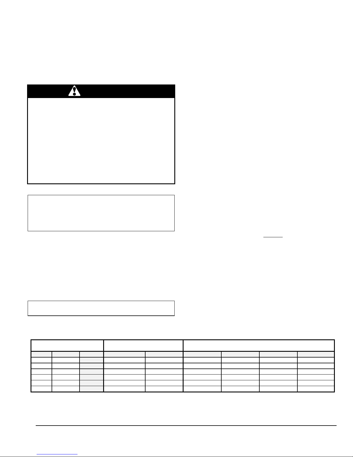
Side-wall venting clearances to combustibles
PORTION OF VENT CLEARANCES
Vent pipe, up to vent terminal* 76.2 mm (3”)
Vent terminal ZERO
*Do not enclose venting
Installation considerations - DV-2000
Select a location for the vent terminal i n accordance with all local and
national codes. The following requ irements shall be considered to be
minimum requirements that can be overridden by stricter local and
national codes.
TABLE 3
TM
-
DNS-0623 Rev. A
The vent shall not terminate
a. Directly above a paved sidewalk or paved driveway that is
located between two buildings, and that serves both buildings;
b. Less than 2.1 m (7') above any paved driveway;
c. Within 1.8 m (6') (in Canada ) of a windo w or door, or mech anical
air supply inlet to any building, including soffit openings;*
d. Within 1.8 m (6') (in Canada) from the soffit of the roof of the
structure;*
e. Above a gas meter/regulator assembly within 0.9 m (3') of a
vertical centreline of the regulator;
f. Within 1.8 m (6') of any gas service regulator vent outlet, or within
0.9 m (3') of an oil tank vent, or an oil fill inlet;
g. Within less than 0.3 m (1') above grade level;
h. Within 1.8 m (6') of any other combustion air inlet;
i. Within 1.8 m (6') of a property line;
j. Underneath a veranda, porch or deck;
k. So that the flue gases are directed at combustible material or any
openings of surrounding buildings that are within 1.8 m (6');
l. Less than 0.9 m (3') from an inside corner of an L-shaped
structure;
m. So that the bottom of the vent termination opening is less than
0.3 m (1') above any surface that may support ice, snow, or
debris;
n. So t hat the flue gases are directed toward brickwork , siding or
other construction, in such a manner that may cause damage
from heat or condensation from flue gases.
For installations in the U.S.A. refer to Sectio n 6.7.3.4 of t he NFPA
31.
FIGURE 1
CAUTION
Most codes have a notwithstanding clause that states
that products of combustion shall not enter the dwelling
under any circumstances, even if all other code
requirements as to construction and location have been
complied with. The installer is ultimately responsible to
do whatever is necessary to ensure that flue gasses do
not enter the dwelling.
7
Page 7

Side wall venting installation - DV-2000™
445 01 4024 05
WARNING
Cuts and abrasion hazard.
Always wear protective gloves and eye protection
when handling the vent material.
The process of cutting and fitting the flexible
venting material exposes the installer to sharp
edges that could cause severe cuts to the skin.
Connection to the furnace breach - DV-2000™
1. Remove the standard breach plate by removin g the brass nu ts;
2. Determine which direction the venting will be routed from the
furnace and then install the special side-wall venting breach plate
provided in the VTK Series vent kit so that the breach plate test
port will be accessible after vent installation. However, do not
install the breach plate with the test port pointing downward.
Tighten the brass nuts;
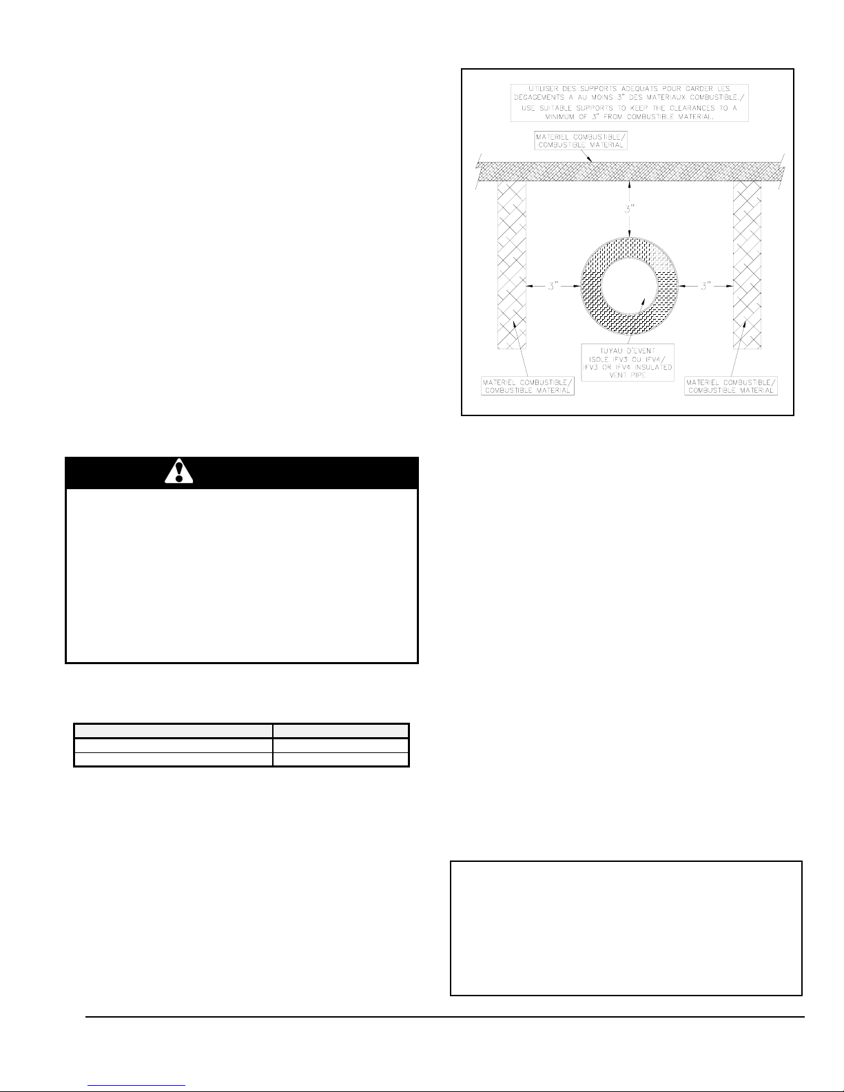
3. The flexible venting h as 4 pieces of corrugated spin sleeve that
has been temporarily screwed on over top of it . Remove t he spin
sleeve completely by unscrewing it in a counter-clockwise
direction;
4. Using tin snips, cut t he aluminium outer sleeve back by 127.0
mm (5") on the IFV Series vent (see Figure 1.1). Ensure the
snips are well adjusted and sharp or th e cut end of the venting
will be too jagged to start the threads of the spin sleeve (see
Figure 1.1);
5. Prepare the furnace breach end of the i nsulated fle x vent by first
screwing the spin sleeve onto the corrugated aluminium jacke t
(see Figure 1.2) until the trailing edge of the s pin sleeve is about
0.3 m (12") from the end of the vent (see Figure 1.3);
6. Pull the insulatio n back to expose the corrugated s tainless steel
core;
7. Cut th e corrugated stainless steel core b ack by 76.2 mm (3") on
the IFV Series vent. You should now have about 76 .2 mm (3") o f
insulation hanging out past the stainless steel core (s ee Figure
1.4);
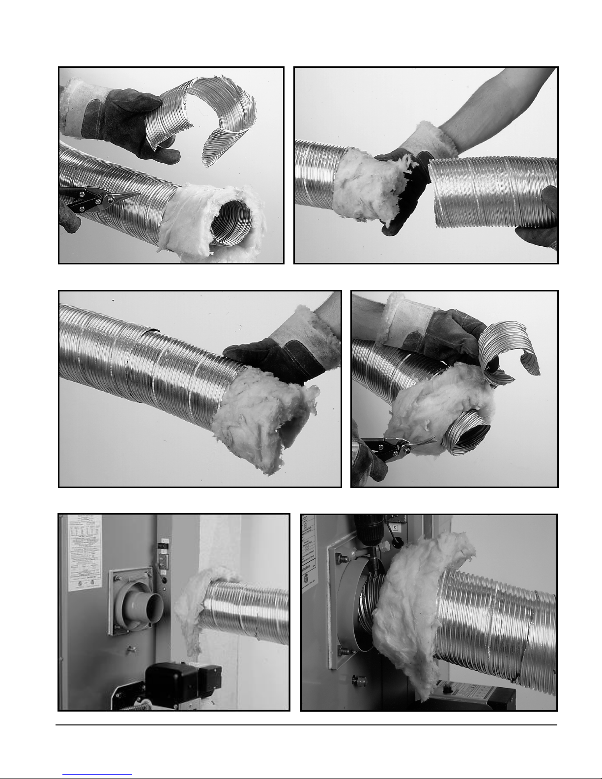
8. Push the stainless steel core ont o the b re ach pipe as far as it will
go (see Figure 1.5) and mechanically attach the vent to the
breach using three of the #8 X 1/2” self-drilling screws provided
with the VTK Series kit. The screws should be equally space d
around the circumference of the s tainl ess st eel c o r e, sta rtin g with
the first screw at top dead centre. Start the drill point of the
screws in the valleys of the corru gations at 9.5 mm –15.8 mm
(3/8”-5/8”) back from the end of the s tainless steel core, so the
screw heads can be properly sealed in the forthcoming
operations (see Figure 1.6);
9. With the stainless steel core no w firmly attached to the breach,
tear off one green gum-sealing str ip from the backing. Wrap the
seal strip around the joint, always keeping the centreline of the
seal strip over the line where the corrugate d stainless steel core
makes the transition to the smooth oute r surface of the breach
pipe. In other words, the seal strip must be ce nt re d over t he j oin t.
After wrapping the seal strip around once, allow 12.7 mm (1/2”)
overlap and tear off the residual length (see Figure 1.7);
10. Break the residual length of seal strip into 3 equal parts a nd stuf f
them onto the screw heads of the stainless steel self-drilling
screws so that the screw heads are completely covered;
11. Two stainless steel band clamps are provided in the VTK Series
kits. Position one stainless steel band clamp over the gum seal
joint so that the edge of the clamp closest to t he breach lines up
with the edge of the gum seal that is closest to the breach.
Ensure that the band will close with an action of one strip sliding
over the other - not under the gear hea d of the draw clamp (see
Figure 1.8). Tighten the band cla mp with considerable torque to
cause the gum seal to be squeezed i nto all crevice s and to ooze
out of the end of the clamp closest to the breach (see Figure 1.9).
The gum will eventually become rubbery;
12. The seal is permanent and should never need to be
disconnected as the breach plate can be r emoved for cleaning
and inspection using the 4-bolt joint;
13. Tuck the vent insulation into the breach collar;
14. Screw the spin sleeve tightly into the breach c ollar for a finished
appearance. Wrap the other end of the spin sleeve with
aluminium tape to cover any metal burrs that may be present
(see Figure 1.10);
15. Bend the venting into the desired radius coming off the breach.
Connection to the vent terminal - DV-2000™
1. Prepare the terminal end of the insulated flex vent by first
screwing the spin sleeve onto the corrugated aluminium jacke t
until the trailing edge of the spin sleeve is about 254.0 mm (10")
from the end of the vent;
2. Using sharp tin snips, c ut the aluminium outer sleeve back by
127.0 mm (5") on the IFV Series vent;
3. Pull the insulatio n back to expose the corrugated s tainless steel
core;
4. Cut th e corrugated stainless steel core b ack by 76.2 mm (3") on
the IFV Series vent. You should now have about 76 .2 mm (3") o f
insulation hanging out past the stainless st eel core ;
5. Push the stainless steel core onto the pipe on the back of the
terminal as far as it will go and mechanically attach the vent to
the terminal using three of the #8 X 1/2” self-drilling screws
provided with the VTK Series kit. The screws sho uld be equally
spaced around the circumference of the stainless steel core,
starting with the first screw at top dead centre. Start the d rill point
of the screws in the valleys of the corrugations at 9.5 mm-15.8
mm (3/8”-5/8”) back from the end of the stainless steel core;
6. With the s tainless steel core now firmly at tached to the terminal,
tear off the other green gum-sealing strip from the backing. Wrap
the seal strip around the joint, al ways keeping the centreline of
the seal strip over the line whe re the corrugated stainless steel
core makes the transition to the smooth outer surface of the
terminal pipe. After wrapping the seal strip around once, allow
12.7 mm (1/2”) overlap and tear off the residual length;
7. Break the residual length of se al strip in to 3 e qual parts and s tuff
them onto the screw heads of the stainless steel self-drilling
screws so that the screw heads are completely covered;
8. Position the o ther stainless steel band clam p over the gum seal
joint so that the edge of the clamp closest to the terminal lines up
with the edge of the gum seal that is closest to the terminal.
Tighten the band clamp with considerable t orque to cause the
gum seal to be squeezed into all crevices and to ooze out of the
end of the clamp closest to the terminal (see Figure 1.11);
9. The seal is permanent and should never need to be
disconnected as the end of the terminal can be opened for
cleaning and inspection by removing the screened end-cone
assembly. Tuck the vent insulation into the recess in the terminal
body;
10. Screw the spin sleeve tightly into the recess for a finished
appearance. Wrap the other end of the spin sleeve with
aluminium tape to cover any metal burrs that may be present
(see Figure 1.12);
11. Bend the venting into the desired radius coming off the terminal.
8
Page 8
THREAD SPIN SLEEVE
ONTO OUTER SLEEVE
CUT OUTER SLEEVE
BACK 5”
THREAD SPIN SLEEVE BACK 10” CUT STAINLESS STEEL
CORE BACK BY 3”
9
FIGURE 1.3 FIGURE 1.4
FIGURE 1.1 FIGURE 1.2
FIGURE 1.5 FIGURE 1.6
INSERT STAINLESS STEEL
CORE ONTO BREECH TUBE
DRIVE THREE STAINLESS STEEL
SCREWS, STARTING NEAR TOP
445 01 4024 05
Page 9

CORRECT BAND
OVERLAP
FIGURE 1.9 FIGURE 1.10
FIGURE 1.7 FIGURE 1.8
SEALANT FLOWING OUT FROM UNDER BAND CLAMP AT
TERMINAL
SEALANT OUTFLOW
FIGURE 1.11
1
0
APPLY THE
SEALANT TO THE
TUBE END
SEALANT OUTFLOW
SEALANT FLOWING
OUT FROM UNDER
BAND CLAMP AT
BREECH
TWIST SPIN SLEEVE TIGHTLY INTO
BREECH COLLAR
445 01 4024 05
Page 10

11
TWIST SPIN SLEEVE TIGHTLY INTO RECESS
INSTALL
STABILIZER
SHROUD
CAULK TO SEAL STABILIZER
SHROUD TO THE WALL
FIGURE 1.13 FIGURE 1.14
FIGURE 1.12
VENT TERMINAL PRESSURE SWITCH.
REFER TO WIRING DIAGRAM FOR ELECTRICAL
CONNECTION.
445 01 4024 05
Page 11

Installing terminal in the wall - DV-2000™
445 01 4024 05
1. Cut a 152.4 mm (6") hole in t he side-wall in accord ance with the
location considerations outlined in the previous section;
2. Fasten the wall plate to the inside-wall using 4 field-provided
fasteners appropriate for the material behind the wall plate.
Depending on the angle of access, the p ressure control bracket
may need to be removed to access the top righ t wall plate scre w
hole. For concrete and block, Tapcon™ scr ews or equivale nt are
recommended. Install the wall plate so that the top of the hole i n
the wall plate is positioned 3.2 mm (1/8”) lower than the top of the
152.4 mm (6") hole in the wall. This will accommodate the proper
downward slope of the terminal, in the direction from the inside to
the outside;
3. Remove the 2 screws fastening the end cone in place and
remove the cone;
4. Remove the 2 screws fastening the stabiliser shroud in plac e and
remove the stabiliser shroud;
5. Insert the main body of the ter min al th roug h t he wa ll plat e so t hat
the end of the terminal extends about 50.8 mm (2") past the
outside wall;
6. Install the stabiliser shroud and replace the two mounting screws.
(see Figure 1.13);
7. On concrete and block wall ins talla tions in particul ar, if it appea rs
that the flange at the back of the stabiliser shroud is not large
enough to cover the irregularities in the hole, a field fabricated
wall plate can be constructed of 304, 316, or 316L stainless steel;
8. Silicone seal the circumference of the joint where the stabiliser
shroud connects to the main body of the terminal;
9. Apply caulking to the back plate of the stabiliser shroud and push
the terminal back firmly against the wall;
10. While pushing down gently on the top of the stabiliser shroud,
install the three 2" stainless steel screws provided with the kit to
secure the back of the shroud to the wall. Do not overtighten the
screws or it will distort the stabiliser shroud. The screws will not
be necessary in a concrete or block wall as the mortar can
provide positive positioning;
11. Tighten the clamp on the wall plate to secure the terminal in
place;
12. Apply more caulking all around the seam where the stabiliser
shroud meets the wall. It is important to have a good seal to
prevent water from entering the dwelling (see Figure 1.14). A
considerable amount of caulking may be necessary for irregula r
wall surfaces such as lapped siding;
13. Install the end cone and replace the two mounting screws;
14. Support the vent and intake air piping so that a 6.4 mm to 12.7
mm (1/4” to 1/2”) downward slope (toward the outsi de ) results for
proper drainage out the terminal body.
Connection of combustion air piping to the terminal - DV-2000™
Refer to Part 1, section 5.3 (1.5.3), Outdo or Combustion Air – Sidewall Venting, DV-2000™ for a complete description.
1.5) AIR FOR COMBUSTION
WARNING
Poisonous carbon monoxide gas hazard.
Comply with NFPA standards for the installation of
Oil Burning Equipment and applicable provisions of
local building codes to provide combustion and
ventilation air.
Failure to provide adequate combustion and
ventilation air can result in personal injury and/or
death.
1.5.1) General
Oil furnaces must have an adequate supply of combustion air. It is
common practice to assume that older homes have sufficient
infiltration to accommodate the combustion air requirement for the
furnace. However, home improvements such as new windows, doors,
and weather stripping have drastically reduced the volume of air
infiltration into the home.
Home air exhausters are common. Bathroom a nd kitchen fans , power
vented clothes dryers, and water h eaters all tend to creat e a negative
pressure in the home. Should this occur, the chimne y becomes less
and less effective and can easily downdraft.
Heat Recovery Ventilation Systems (H RVs) are gaining in popularity.
HRVs are not designed to supply combustion air. If not properly
balanced, a serious negative pressure co ndition could develop in the
dwelling.
1.5.2) Contaminated Combustion Air
Installations in certain areas or types of structures will increase the
exposure to chemicals or Halogens which may harm the furnace.
These instances will require that only outside air be used for
combustion.
The following areas or types of structures may contain or be exposed
to certain substances, potentially requiring outside air for combustion:
a. Commercial buildings;
b. Buildings with indoor pools;
c. Furnace s insta lled ne ar ch emica l storag e ar eas.
Exposure to the following substances:
a. Permanent wave chemicals for hair;
b. Chlorinated waxes and cleaners;
c. Chlorine based swimming pool chemicals;
d. Water softening chemicals;
e. De-icing salts or chemicals;
f. Carbon tetrachloride;
g. Halogen type refriger ants;
h. Cleaning solvents (such as perchloroethylene);
i. Printing inks, paint removers, varnishes, etc.;
j. Hydrochloric acid;
k. Solvent based glue;
l. Antistatic fabric softeners for clothes dryers;
m. Acid based masonry cleaning materials.
1.5.3) Ducted outdoor combustion air
Three burners are set up to duct outside combus tion air direc tly to the
burner: the Beckett AFII and Riello 40 -BF for side-wall venting using
the new DV-2000™ venting system, and t he Becke tt AF G for us e wit h
conventional chimney venting. The Riello 40-F is not suitable for
direct-connected outdoor air.
CAUTION
The use of ducted outside combustion air is mandatory
for the DV-2000™ venting system. This system
operates on a balanced flue principle and will not
function properly if the combustion air piping is not
attached and sealed at all connections between the
vent terminal and burner inlet.
12
Page 12

Outdoor combustion air kits – chimn ey v enting
445 01 4024 05
The following kit has been certified f or use on this appliance. The kit
contains an important safety featu re, namel y a vacu um relief valve, or
VRV. During normal operation th e burner aspirates outdoor ai r. If the
intake terminal ever becomes partially blocked o r fully blocked from
ice or snow etc., the VRV will open to allow a proportion of air from the
dwelling to enter the burner thus maintaining proper combustion. Once
the blockage is removed, the VRV will close and the burner will draw
all air from the outdoors again.
CAS-2B Components (except air duct ) for the Beckett AFG burner:
The kit includes the intake terminal, vacuum relief valve (VRV) and
special air boot connection with integral air adjust ment means for the
AFG burner. The CAS-2B can be used with a 101.6 mm (4")
galvanized steel air duct or with a 101.6 mm (4") flexible alumini um ai r
duct. It is recommended that the metallic air ducting material be
insulated from the air intake up to 1.5 m (5') from the burner, to avoid
condensation on the outside of the intake pipe.
CAUTION
The CAS-2B does not turn the furnace installation into a
direct vent system. Therefore, the building structure
must provide for adequate combustion air to be
delivered to the Vacuum Relief Valve. The burner will
need to draw combustion air from the VRV’s
surroundings if the intake ever becomes blocked.
Therefore, non-direct vent installation codes must be
followed.
CAD-1 This air duct kit consists of 7.6 m (25') o f insulated UL/U LC
Listed Class 1 air duct and two 101.6 mm (4") steel band clamps . The
duct incorporates a corrugated flex ible aluminium c ore, su rrounded by
fibreglass insulation and a vinyl vapour barrier.
Comprehensive installation instructions are provided with the kit.
Outdoor combustion air – side-wall venting, DV-2000™
The new DV-2000™ venting system is a sealed system and
completely isolates the furnace from the inte rior of the building. The
burner is totally unaffected by any pressure fluctuations within the
building which makes it ideal for tight home construction.
The DV-2000 ™ venting system requires a dditional parts, which are
not included with the kit. These additional parts must be constructed of
3" Schedule 40 PVC, PVC-SWV, SDR-26, SDR-21, Septic Sewer
Pipe, or ABS plastic pipe, fittings and sealant. Also, installation
procedures, piping and fittings must conform to the following ANSI
/ASTM standards:
PVC ASTM D-1785
SDR26, SDR21 ASTM D-2241
Septic Sewer Pipe ASTM D-2729
PVC-DWV ASTM D-2665
PVC Primer and Solvent Cement ASTM D-2564
ABS Pipe and Fittings ASTM D-2235
Procedure for Cementing Joints ASTM D-2855
Additional parts required (not included in VTK kit)
a. 3" elbow fitting as required;
b. 3" plastic pipe;
c. 3" 90° elbow, female-female(for terminal);
d. 3" female to 2 inch female reducer (Riello 40-BF burner only);
e. 2" 90° elbow, street type, female-male (Riello 40-BF burner only);
f. 3" female-female PVC or ABS coupling (not sewer pipe) (Beckett
AFII burner only);
g. Transition bushings to go from PVC or ABS to ASTM D2729
Septic Sewer Pipe (if applicable).
If PVC fittings are mixed with ABS fittings, use solvent ceme nt that is
approved for bonding the two plastics.
Intake pipe length - DV-2000™
The DV-2000 ™ venting system has been certified for 37 equivalent m
(120 equivalent feet) of 3" intake pipe. Count a 90° elbow as 10
equivalent feet and a 45° elbow as 5 equivalent feet in the calculation.
For example:
1 1.5 m (5') length = 1.5 equivalent m (5 equiv. feet)
2 3.0 m (10') lengths = 6.0 equivalent m (20 equiv. feet)
3 90° elbows = 9.0 equivalent m (30 equiv. feet)
2 45° elbows = 3.0 equivalent m (10 equiv. feet)
1 90° elbow (terminal) = 3.0 equivalent m (10 equiv. feet)
1 90° elbow (Burner) = 3.0 equivalent m (10 equiv. feet)
Total = 25.5 equivalent m (85 equiva lent feet) ;
this is below the 37 equivalent meters (120 equiv. feet).
Intake pipe installation - DV-2000™
Obtain the necessary additional parts, to comple te t he inst allation , an d
start by piping at the burner. If the optional vestibule has been
installed, remove the appropriate knockouts in the side panels of the
vestibule. The lower 127.0 mm (5") knockout in t he righ t-hand p anel is
used for the Beckett AFII burner. The high er 127.0 mm ( 5") knockout s
on the right and left-hand pa nels are for righ t or left connectio n to the
Riello 40-BF burner.
Beckett AFII burner
Remove the burner intake cover by removing the 3 screws sec uring it
in place. Discard the cover and screws. Apply silicone liberally around
the end of a 3" coupling and fully insert the siliconed end into the
burner opening. Fasten securely with 3 self-tapping sheet metal
screws.
Riello 40-BF burner
Fully insert the female end of the 2" 90° street elbow into the
combustion air fitting on top of the burner. Faste n securely with 3 selftapping sheet metal screws. Cement the 2" end o f t he 3" fe mal e to th e
2" female reducer onto the male end of the 2" 90° street elbow. If
these parts are not easily obtained, use a 3" 90 ° street elbow with the
male end fitted over the combustion air fitting. The fitting will have to
be silicone sealed as the fit is a bit loose. Fasten securely with 3 selftapping sheet metal screws.
Terminal connection
Insert the 3" 90° female-female elbow onto the stainless steel air
intake fitting located on the right side of the vent terminal (viewe d from
the rear). Fasten securely with 3 self-tapping sheet metal screws.
Intermediate piping
Pipe as required between the term inal and t he burn er. Ens ure th at th e
3" piping is routed and supported in accordance with local and
national codes. Obey minimum furnace clearances to combustibles
when routing any section of 3" piping in the vicinity of the furnace. If
Septic Sewer Pipe is to be used, install transition bushings on the 3"
female ends of the fittings at the burner and at the terminal. Transition
bushings are readily available and are required because 3" PV C and
ABS pipes have a typical outside diameter of 3.5", whereas Septic
Sewer Pipe has a typical outside diameter of 3.25".
1.6) OIL TANKS AND LINES
Check your local codes for the installation of the tank and accessories.
A manual shut-off valve and an oil filter shall be installed in sequenc e
from tank to burner. Be sure that the oil line is clean before connecti ng
to the burner. The oil line should be protected to eliminate any
possible damage. Installations having the fuel oil tank below burner
level must employ a two pipe fuel supply system with an ap propriate
fuel pump. For more than a 2.4 m (8') rise use a 2 stage pump; for
more than a 4.9 m (1 6') rise, an auxiliary pu mp .
13
Page 13

445 01 4024 05
Follow the pump instructions to determine the size o f pipe yo u need i n
relation to the rise, or the horizontal distance.
At the beginning of each heating season or onc e a year, check the
complete oil distribution system for leaks.
1.7) BURNER INSTALLATION
Mounting the burner
1. The warm air furnace burner mounting plate has a 4-bolt
configuration;
2. Position the mounting gasket between the mounting flange and
the appliance burner mounting plate. Line up the holes in the
mounting flange with the studs on the appliance mounting plate
and securely bolt in place.
After the burner is mounted
1. Remove drawer assembly or air tube combination;
2. Install nozzle (see specifications);
3. Confirm electrode settings;
4. Make the electrical connections;
5. Complete oil line connections.
CAUTION
Do not turn on the burner until you have checked:
Checking the polarity
Oil burners used on furnaces have solid state co ntrol systems which
make them sensitive to the proper con nections of the hot and n eutral
power lines. The controls will be damaged if the 2 lines are reversed.
1. Set your voltmeter to line voltage;
2. Place one prong on your grounded electric entry box and one
prong on the black wire;
3. Read the voltage;
4. If the voltage is zero, check the white wire. If line voltage shows,
reverse the 115-volt leads entering the furnace junction box;
5. If you do not have a voltmeter, use a pilot light.
DNS-0864 Rev. A
Checking the nozzle
The burner is equipped with an appropriate nozzle. However, if
another size or a replacement nozzle is required, use the
manufacturer’s nozzle data concerning spray angle, as shown in
Table 4. Note that all nozzle sizes are based on a pump pressure of
100 PSI.
Always select nozzle sizes by working back from the actual desired
flow rate at operat in g pr e s sur e , and not by the nozzle ma r k in g.
FIGURE 2
Checking the air and turbulator settings
Before starting the burner for the first time, adjust the air and turbulator
settings to those listed in Table 4. Once the burner becomes
operational, final adjustments will be necessary.
Checking the fuel supply system
Fuel Specifications
NOTE: Use No.1 or No.2 Heating Oil (ASTM D396) or
in Canada, use No.1 or No.2 Furnace Oil.
Before starting the burner, be sure the fuel tank is filled with clean oil.
NOTE: You may notice a slight odor the first time your
furnace is operated. This will soon disappear. It is only
the oil used on certain parts during manufacturing.
WARNING
Fire and explosion hazard.
Use only approved heating type oil in this furnace.
DO NOT USE waste oil, used motor oil, gasoline or
kerosene.
Use of these will result in death, personal injury
and/or property damage.
IMPORTANT
When using nozzle sizes of less than .75 USGPH, the
Installation Code for oil burning equipment requires the
installation of a 10 (or less) micron filter in the fuel oil
line. ICP requires that this practice be followed in order
to keep the lifetime heat exchanger warranty intact.
1.8) BLOCKED VENT SHUT-OFF (BVSO)
For chimney venting
WARNING
It is imperative that this device be installed by a
qualified agency.
This device is designed to detect the insufficient evacuation of
combustion gases in the event of a ven t blockage. In suc h a case the
thermal switch will shut down the oil burner. The device will then need
to be re-armed MANUALLY.
Refer to the wiring diagrams and the detailed instructions supplied
with the BVSO for the installation and wiring procedures. The leng th of
wires supplied with the unit is such that the safety device must be
installed between the flue outlet of the appliance and the draft
regulator, as indicated in the instructions.
It is further imperative that the BVSO be maintained annually
more details refer to the instructions supplied with the device itself, as
well as Section 3. of this Manual.
. For
14
Page 14

445 01 4024 05
CAUTION
A positive pressure venting system (Sealed Combustion
System or Direct Vent) MUST NOT use the BVSO. Follow
the instructions supplied with the venting system.
1.9) INSTALLING ACCESSORIES
WARNING
Electrical shock hazard.
Turn OFF electric power at fuse box or service
panel before making any electrical connections and
ensure a proper ground connection is made before
connecting line voltage.
Failure to do so could result in bodily injury or
death, property damage.
1.9.1) Electronic air cleaner
Wire terminals are provided to direct 115 volts @ 0.5 Amp maximum
to an Electronic Air Cleaner (EAC). Power will be available to the EAC
at all times, so it must incorporate a flow proving switch if it is to be
wired into the furnace control box. Most modern EACs have the
required integral airflow proving switch. Wire the Electronic Air Cleaner
between terminals #5 and #2. Refer to wiring diagram, Figure 6.
1.9.2) Humidifier
The red wire from burner ca n be used to direct 1 15 volts
maximum to the transformer
will be energized anytime the burner is operating in the “Heating
Mode”. Refer to wiring diagram, Figure 6.
powering the humidifier. The humidifi er
1.9.3) Air conditioning
An air conditioning coil may be i nstalled on the supply air side only.
Also, notwithstanding the evaporator coil manuf acturer’s instructions,
a minimum of 6 inches clearance must be allowed between the bottom
of the coil drain pan and the top of the heat exchanger. Wire the
thermostat and condensing unit contactor as indicated in the wiring
diagram (Figure 6).
1.9.4) Ductwork and Filter
Installation
Design and install the air distribution system to comply with Air
Conditioning Contractors of America manuals or other approved
methods that conform to local and/or national codes and good trade
practices.
@ 1.0 Amp
CAUTION
When ducting supplies air to a space other than where
the furnace is located, the return-air ducts must be
sealed and also be directed to the space other than
where the furnace is located. Incorrect ductwork
termination and sealing will create a hazardous
condition which can lead to bodily harm.
Install air conditioning cooling coil (eva porator) on downstream side
from the supply air plenum of the fu rnace. If a separate evaporator
and blower unit is used, install appropriate sealing dampers for air flow
control. Cold air from the evaporator coil goi ng through the furnace
could cause condensation and shorten furnace life.
CAUTION
Dampers (purchased locally) MUST be automatic.
WARNING
Poisonous carbon monoxide gas hazard.
Do NOT draw return air from inside a closet or
utility room. Return air duct MUST be sealed to
furnace casing.
Failure to properly seal duct can result in death,
personal injury and/or property damage.
WARNING
Poisonous carbon monoxide gas hazard.
Install evaporator coil on the supply side of the
furnace ducting.
Evaporator coil installed in return side ducting can
cause condensation to form inside heat exchanger
resulting in heat exchanger failure. This could
result in death, personal injury and/or property
damage.
15
Page 15

PART 2
445 01 4024 05
OPERATION
2.1) MANUAL OPERATION SWITCHES
DNS-0604 Rev.B
2.2) SEQUENCE OF OPERATION
2.2.1) Sequence of operation - Beckett AFII
Side-wall venting
1. On the Beckett AFII burner, the T-T terminals have to be
jumpered on the primary control of the burner;
2. Normally open contact (W-R) on SPDT relay closed when
thermostat calls for heat;
3. Burner motor starts and spark is established. The burner motor
fan pre-purges the combustion cham ber and vent for 15 to 20
seconds, establishing the combustion air pattern;
4. After pre-pur ge period, solenoid valve opens, allowing oil to flow
through nozzle;
5. The ignition transformer spark ignites oil spray;
6. Cad cell senses flame and burner continues to fire;
7. After Fan-Limit Control heats up to the factory set point, the
circulating air blower starts;
8. The circulating ai r blower, burner motor and igniti on transformer
remain on until the thermostat is satisfied. Also, the solenoid
valve remains open;
Thermostat is sat isf ie d:
9. SPDT relay contacts open, solenoid valve closes, burner fan
motor post-purges the combustion cham ber and vent for a preset time of 15 seconds. The ignition transformer also continues to
spark for this time period;
10. During the post-purge cycle, the Fan-Li mit Control cools down to
the factory set point of 32°C (90°F) and the circulating ai r blowe r
turns off.
2.2.2) Sequence of operation - Riello 40-BF
Side-wall venting
1. Normally open contact (W-R) on SPDT relay closed when
thermostat calls for heat;
2. Burner motor starts. The burner motor fan pre-purges the
combustion chamber and vent for 10 seconds, e stablishing the
combustion air pattern. During this time the solenoid valve
holding coil pressure will be approximately 100 psig;
FIGURE 3
3. Afte r the pre-purge p eriod, the solenoi d valve opens, allowing oil
to flow through the nozzle. At the same time, th e burner motor
ignition coil produces spark;
4. The ignition transformer spark ignites the oil spray;
5. Cad cell senses flame and burner continues to fire. Ignition
transformer ceases sparking;
6. After Fan-Limit Control heats up to the factory set point, the
circulating air blower starts;
7. The circulating air blower an d burner motor remain on until the
thermostat is satisfied. Also, the solenoid valve remains open;
Thermostat is sat isf ie d:
8. Rel ay contacts open, solenoid valve closes and the burner fan
motor post-purges the combustion cham ber and vent for a preset time of up to 15 seconds (5 inch breach model only);
9. During the post-purge cycle, the Fan -Limit C ontrol BI-metal co ols
down to the factory set point of 3 2°C (90°F), and the circulati ng
air blower shuts down.
NOTE: With burner relay contact open, the Riello 40BF will post-purge when 115 volt power is applied to the
burner.
2.2.3) Sequence of operation - Beckett AFG and
Riello 40-F - Chimney venting
1. On the AFG burner, the T-T te rminals have to be jumpered on
the primary control of the burner;
2. Normall y open contact (W-R) relay closes when thermostat calls
for heat;
3. Burner motor starts. The burner motor fan pre-purges the
combustion chamber and vent for 10 to 15 seco nds, establis hing
the combustion air pattern. After the pre-purge period, the
solenoid valve opens, allowing oil to flow through nozzle. At the
same time, the burner motor ignition coil produces a spark;
4. Spark ignites oil droplets;
5. Cad cell senses flame and burner continues to fire. Ignition
transformer ceases sparking;
6. After Fan-Limit Control heats up to the factory set point, the
circulating air blower starts;
7. The circulating air blower an d burner motor remain on until the
thermostat is satisfied;
Thermostat is sat isf ie d:
8. Relay contacts open, solenoid valve closes, burner fan motor
shuts down and the ignition transformer ceases sparking.
2.2.4) Sequence of operation - DV-2000™
Venting system
Normal operation
1. Before a call for heat, the contacts of the pressure switch are
closed;
2. When the room thermostat calls for heat, the normally open
contact W-R closes, the burner blower starts and creates suc tion
in the intake piping circuit and pressure in the vent piping circuit;
3. The differential pressure set poi nt of the pressure switch is not
exceeded and the thermostat circ uit remains close d until the call
for heat has ended.
16
Page 16

445 01 4024 05
Abnormal operation
Start-up
1. When the room thermostat calls for heat, the normally open
contact W-R closes, the burner blower starts and creates suc tion
in the intake piping circuit and pressure in the vent piping circuit;
2. If there is a blockage in the intake or vent openings to c ause a
pressure differential beyond the set poin t of the pressure switch,
then the thermostat circuit is opened and the burner will go into a
15 seconds post-purge and then shut down;
3. Once the burner blower shuts down, after the post-purge, the
pressure switch contacts will re-close. If the call for heat remains,
the burner will re-start. If the blockage still exists, th e thermostat
is again opened, and the burner post- purges agai n. The postpurge function thus becomes an inherent anti-short cycling
device;
4. The unit will essentially go into a continuous re-cycling/postpurge mode with no heat being suppli ed to the dwelling, which
will prompt a service call;
5. If, d uring the re-cyclin g/post-purges, th e blockage of the termi nal
is removed, the burner will immediately fire up at the end of the
current post-purge cycle.
During operation
If the terminal vent or intake openings become blocked to th e point
where the set point of the pressure switch is e xceeded, duri ng a firing
cycle, the burner flame will shut down and the burner will go into the
indefinite recycling/post-purge mode as described above, until the
blockage is removed.
2.3) CHECKS AND ADJUSTMENTS
2.3.1) General
During initial start-up and subsequent yearly maintenance calls, the
furnace must be thoroughly tested.
Open the oil bleed port screw and start the burner. Allow the oil to
drain into a container for at least 10 seconds. Slo wly clos e and ti ghte n
the bleed screw. The oil should fl o w absol ut el y f ree of whi te s tr eaks o r
air bubbles to indicate that no air is being drawn into the suction side
of the oil piping and pump. Fire the burne r. Adjust the oil pressure as
indicated in Table 4.
IMPORTANT
The burner must be put in operation for at least 10
minutes before any test readings are taken. For new
installations, set up the burner to the settings in Table 4
before firing. These are rough adjustments but they will
ensure that the burner will start and run smoke-free in
advance of the fine adjustments being made.
2.3.2) Restart after burner failure
1. Set thermostat lower tha n the room temperatur e;
2. Press the reset button on the burner primary control (relay);
3. Set thermostat higher than the room temper at u re for 10 secon ds,
then set lower than room temperature. This will start the
pre-purge cycle. Repeat twice;
CAUTION
Do not attempt to start the burner when excess oil has
accumulated, when the furnace is full of vapour, or
when the combustion chamber is very hot. Always keep
the supply valve closed if the burner is shut down for an
extended period of time.
4. Set thermostat higher than the room temp er atur e;
5. If the burner motor does not start or ignition fails, turn off the
disconnect switch and CALL A QUALIFIED SERVICE
TECHNICIAN.
2.3.3) Combustion chamber curing
Some moisture and binders remain in the ceramic combustion
chamber after fabrication. It is important to clear the chamber of th is
residue before testing. If you smoke test befo re curing, t he instrumen t
may become damaged. To cure the chamber, run the unit for 3
consecutive cycles, with 3 minutes of elapsed time in b etween each
cycle. Each burn cycle should be 3 minutes long. The exhaust will
have a pungent odour and produce a white cloud of steam.
2.3.4) Smoke / CO2 test
1. On chimney installations, pierce a test hole in the smoke pipe 1 8
inches above the furnace breach. On side-wall vented
installations, remove the threaded cap from the extended test
pipe that is welded into the 4-bolt breach pla te. Insert the smoke
test instrument probe into the open hole;
2. From a cold start, let the unit operate during 5 to 10 minutes;
3. Set the burner air setting until just a trace of smoke results (#1 on
the Bacharach scale);
4. Take a CO
smoke reading was taken and make note of it. Exa mple: 13.8%
of CO
5. Adjust th e burner air setting to obtain a CO
(or a O
the #1 smoke. Example: 12.3% of CO
6. This method of adjusting the burner will result in clean
combustion and ensure the proper functioning of the system.
sample at the same test location where the #1
2
or 2.5% of O2;
2
reading 1.5% lower
reading 2.0% higher) than the reading associat ed with
2
2
or 4.5% of O2;
2
2.3.5) Perform the supply air temperature rise test
1. Operate the burner for at least 10 minutes;
2. Measure the temperature of the air in the return air plenum;
3. Measure the temperature of the air in the largest trunk coming off
the supply air plenum, just outside the range of radiant heat
coming off the heat exchanger; 0.3 m (12") away from the
plenum on the main take-off is usually sufficient;
4. The temperature rise is calculated by subtracting the return air
temperature from the su pply a ir tem pera ture ;
5. If the temperature rise exceeds the temperature specified in
Table 4, change to the next higher blower speed tap until the
temperature rise falls to this temperature or below. If the
excessive temperature rise cannot be reduced b y increasing fan
speed, investigate for ductwork restricti on (s), dirt y or im prop er ai r
filter, overfiring caused by excessive pump pressure, or improper
nozzle sizing.
2.3.6) Vent temperature test
1. Afte r 5 to 10 minutes of operation, place a thermometer in the
test hole located in the breach pipe;
2. Th e vent temperature should be between 204 and 302°C (400
and 575°F). If not, check for improper air temperature rise, pump
pressure, nozzle size, or for a badly sooted heat exchanger;
3. Check the minimum permitted temperature at the base of the
chimney. Refer to the installation code in order to avoid the risk
of condensation in the chimney .
17
Page 17

445 01 4024 05
2.3.7) Overfire pressure test procedure
1. To read the pressure, replace the glass with the washe r supplied
with the appliance;
2. After the test, put the glass back in place in the sight glass
assembly;
3. Verify that the pressure readi ng c orres ponds to th e one sp ecified
in Table 4. Also see Figure 3.1.
DNS-0703 Rev. A
FIGURE 3.1
2.3.8) Fan-Limit adjustment
Modification of the “FAN ON” and “ HI” limit settings on the Fan-Limit
can cause malfunctioning of the furnace and result in pre mature wear
of the heat exchanger.
CAUTION
Modification of the factory set limits will void the
warranty.
2.3.9) Limit control check
After operating the furnace for at least 15 minutes, restrict the return
air supply by blocking the filters or the return air register and allow the
furnace to shut off on High Limit. The burner will shut off but the
blower will continue to run.
Remove the obstruction and the burner shou ld resta rt af ter a f ew
minutes.
DNS-0355 Rev. B
FIGURE 4
90˚ F Limit ‘’FAN OFF’’ 1
130˚ F Limit ‘’FAN ON’’ 2
200˚ F Limit ‘’HI’’ 3
2.3.10) DV-2000™ Blocked intake / blocked vent
test
On side-wall vented furnaces, the DV-2000™ venting system
incorporates a safety shutdown system that will shut the burner down
before #1 smoke occurs due to the prese nce of a blocked intake or
blocked vent outlet. Test the system as follows:
1. Ensure that the furnace has been running for at least 10 minutes;
2. Gradually block the intake. The burner flame sho uld shut down
before a #1 smoke reading occurs;
3. Gradually block the vent outlet. The burner flame should shut
down before a #1 smoke reading occurs;
4. If the burner does not shut down before #1 smoke occurs, ensure
that the burner is set up accordi ng to Part 2, section 3.4 (2 .3.4).
Perform the CO
operating headroom required by the instructions;
5. If the burner still does not shut down before #1 s moke occurs,
check for a blockage in the pressure hose, or at the hose
connection points.
/ Smoke Test, and allow for the 1.5% CO2
2
IMPORTANT
The DV-2000™ safety shutdown system will shut down
the burner flame during a blocked intake or blocked
vent condition if and only if the burner has been set up
and calibrated in accordance with Part 2, section 3.4
(2.3.4). Perform the CO2 / Smoke Test. For instance, if
the burner is adjusted and final-set to a #1 smoke
condition during normal operation, the burner flame
cannot possibly shut down before #1 smoke occurs
during a blockage condition.
2.3.11) BVSO performance test
The purpose of the following tes t is to check that the electrical outle t
on the furnace, designated to the BVSO, is functional.
1. Start up the burner;
2. Remove the three-pole plug from the BVSO outlet on the
furnace;
3. The burner must shut-off immediately, while the blower continues
to run to the end of the cool-down cycle.
If the test is not in line with the above, call a QUALIFIED SE RVICE
TECHNICIAN.
18
Page 18

PART 3
445 01 4024 05
MAINTENANCE
3.1) GENERAL
Preventive Maintenance
“Preventive maintenance” is the best way to avoid unnecessary
expense and inconvenience. Have your heating system and
burner inspected at regular intervals by a qualified service
technician.
After inspection, a complete combustio n test must be performed a fter
each annual service of the unit to maintain optimum performance and
reliability.
Do not tamper with the unit or controls. Call a qualified service
technician.
Before calling for service, check the following:
1. Check oil tank gauge and check if the oil tank valve is open;
2. Check fuse or circuit breaker;
3. Check if shut-off switch is “ON”;
4. Reset thermostat above room te mper atur e;
5. If ignition does not occur, turn off the disconnect switch and call a
qualified service technician.
When ordering replacement parts, specify the complete furnace
model number and serial number.
WARNING
Electrical shock hazard.
Turn OFF power to furnace before any disassembly
or servicing.
Failure to do so can result in bodily injury and/or
death, property damage.
3.1.1) Heat exchanger
The entire heat exchanger should be inspected annually for soot
accumulation. If the burner is operating nor mally there should be v ery
little soot accumulation. If the heat excha nger requires scale re moval,
use a wire brush first, to loosen the scal e and then vacuum the soot
and scale that has fallen into the s econdary heat exchanger (radia tor)
section. You will find that a 0.9m (36”) long flexible hose attachment
will be helpful to reach into the back of the radiator; a piece of 12.7
mm (1/2”) flexible gas connector, or a piec e of 12.7 mm (1/2”) liquidtight vinyl jacket metallic electrical conduit works well as a makeshift
device.
Cleaning the heat exchang er
Remove the 4-bolt flange from the fr ont of the furnace to expose th e
clean-out port and check for soot deposits. If t here is very little soot in
the radiator section visible from the clean-out port, you will not need to
clean it. However, if you notice scaling in the radiator, you should
remove the scale.
The wrap-around radiator can now be cleaned entirely from the front
inspection port. Also, the furnace has external cle an-out ports so the
soot does not fall into the fan compartment during the cleaning
operation.
IMPORTANT
Do not vacuum the ceramic chambers—they are easily
damaged.
Soot will have collected in the first sections of the heat exchangers
only if the burner was started after the combustion chamber was
flooded with fuel oil, or if the bu rner has been oper ating in a severely
contaminated condition.
3.1.2) Refractory firepot
Remove the burner and check the firepot.
IMPORTANT
Use extreme care if cleaning of the pot is required. After
firing, the pot becomes very fragile. Do not use any
commercially available soot remover. This furnace has
a fibre type refractory combustion chamber. Normal
servicing of this unit does not require cleaning of the
combustion chamber.
If the pot is damaged, it must be replaced. A dama ged pot could lead
to premature heat exchanger failure. Cracking of the firepot is normal,
however, replace the pot only if the cracks have propagated more
than 2/3 the way through the wall thickness. The average wall
thickness of the firepot is 19.1 mm (3/4”).
Flooding of the firepot
Flooding can occur when the oil primary control has been reset a
number of times in a no-heat situatio n. Each time oil is fired into the
pot and does not ignite, it is absorbed into the pot. Even if the burner is
removed and the pot is felt for wetness, it is difficult to assess the
degree of oil absorption by the pot.
There is only one way to pr operly service a floo ded firepot , and th at is
to change it.
CAUTION
If you observe the red warning light on the burner, push
ONLY once to try and restart. If the burner will not start,
call a qualified service technician. Do NOT press the
button again.
Self-aligning firepot
The primary heat exchange r of the furnace is comprised of an upper
and lower half. The lower half is essentially a “can” that contains a
self-aligning firepot. The firepot fits into the bottom half in one directio n
only.
Removing the firepot
The firepot is seldom replaced, b ut when it has to be replaced one
must simply:
1. Remove the burner;
2. Remove the burner Limit Control;
3. Remove the breach plate;
4. Remove the front panel;
5. Remove the brass nuts on the stainless steel heat exchanger
studs;
19
Page 19

445 01 4024 05
6. Pry the bottom half of the heat exchanger apart by using the
designated prying tabs;
7. Remove th e bottom half of the heat e xchanger through the f ront
of the furnace;
8. Pull the firepot up and out of the bottom half of the heat
exchanger;
9. Remove th e old sealing gasket from the flan ge of the upper half
of the heat exchanger;
10. Scrape any residual gasket material off the matching flanges of
the heat exchanger.
Replacing the firepot
1. Align the slot at the f ront part of the firepot with the b urner tube
sleeve and gently lower the firepot into the bottom half of the heat
exchanger;
2. Holding the fire pot near the perimeter, gently pus h the firepot all
the way into the bottom half of the heat exchanger until it is
properly seated;
3. Thoroughly wet the gasket with water using a sp ray pum p bottle,
position the tabs over the studs, and push the gasket upward
against the sealing flange of the upper half of the heat
exchanger;
4. Install the brass nuts on the studs by engaging only 2 or 3
threads;
5. Position the bottom half of the heat exchanger underneath the
upper half and align the bottom half so that the slots in the bolting
tabs engage the stainless steel studs. T he re is n o f urth er ne ed to
hold onto the bottom half as it will now be suspended on the stud
nuts;
6. Push upward on the housing a nd thread the nuts finger-tight as
far as possible;
7. Intermittently tighten the brass nuts with a wrenc h in a sequence
that will pull the heat exchanger halves together evenly. Tighten
all nuts to 90 inch-lbs torque once and then alterna tely re-tighten
all nuts again to 100 inch-lb. THE RE-TIGHTENING SEQUENCE
IS ABSOLUTELY NECESSARY TO ENSURE A TIGHT JOINT;
8. Re-assemble the front panel, breach plate, Limit Control and
burner in reverse sequence to their removal;
9. Follow the ins tructions for starting the b urner for the first time to
cure the firepot and perform combustion checks. See Section
2.3.
3.1.3) Drawer assembly
Remove the drawer assembly. Clean all foreign matter from the
retention head and electrodes. If a Beckett AFG burner has been
installed, the burner will have to be removed to check the retention
head.
3.1.4) Nozzle
Replace the nozzle with the one specified in Table 4.
3.1.5) Oil filters
Tank filter
The tank filter should be replaced as required.
Secondary filter
The 10 (or less) micron filter cartridges should be replaced annually.
3.1.6) Air filters
Air filters are the disposable type. They s hould be replaced at least
once a year. Dusty conditions, presence of animal hair etc. may
require much more frequent filter changes. Dirty filters will impact
furnace efficiency and increase oil consumption.
3.1.7) Motor lubrication
Do NOT lubricate the oil burner motor or the direct driv e blowe r motor
as they are permanently lubricated.
3.1.8) CAS-2B combustion air kit (chimney
venting)
If used, check the CAS-2B combustion air kit for proper operation.
Check to see that the inlet screen is not plu gged. Block the air inlet
completely and ensure that a zero smoke reading res ults. If a zero
smoke reading is not obtained, s et up the burner as indicated in Part
2, section 3.
Gradually block off the intake. The CO
of 0.5 percentage points at the fully bl ocked condition. If not, check
that the VRV gate is pivoting freely and that the pivot rod is in a
horizontal position. Also, check that the counterweight has been
properly adjusted in accordance with CAS-2B installation instructions.
should increase to a maximum
2
3.1.9) Blocked Vent Shut-Off (BVSO) Cleaning
For continued safe operation, the Blocked Vent Shut-Off System
(BVSO) is required to be inspected and maintained annually by a
qualified agency.
1. Disconnect the power to the appliance.
2. Remove the two screws holding on the BVSO assembly cover.
3. Remove the cover.
4. Remove the two screws holding the thermal switch to the
assembly base.
6. Without removing the electrical wires, remov e the thermal s witch
and remove any build-up from the thermal switch surface.
CAUTION
Do not dent or scratch the surface of the t hermal
switch. If the thermal switch is damaged,
replacement is required.
6. Clear and remove any build-up or obstruction inside the heat
transfer tube.
7. Re-mount the thermal switch to the assembly base.
8. Re-attach the assembly cover with the screws removed in step 2.
9. Re-establish power to the appliance.
20
Page 20

445 01 4024 05
PART 4
INFORMATION
Model:
Installation date of the furnace:
Service telephone # - Day:
Dealer name and address:
START-UP TEST RESULTS
Nozzle:
Burner adjustments:
CO
% Smoke scale: (Bacharach)
:
2
Gross stack temperature:
Ambient temperature:
Chimney draft:
Overfire draft:
Test performed by:
Primary air
Fine air
Drawer Assembly
Serial number:
Night:
Pressure:
°F
°F
" W.C.
" W.C.
lbpsi
21
Page 21

TABLE 4
445 01 4024 05
Technical specifications
Model :
RATING AND PERFORM ANCE
Firing rate (USGPH) 0.50 0.63 0.75 0.72
Input (BT U/h) 70 000 88 200 105 000 100 800
Heating capacity, chimney installation (BTU/h) 58 000 72 500 85 200
Heating capacity, side-w all installation (BTU/h) 58 200 72 600 85 700 83 000
Minimum - maximum tem perature rise
Flue draft, (Chimney), (Side-w all)
Overfire pressure (chimney), (Side-w all)
BECKETT BURNER, CHIMNEY INSTALLATION
Burner tube insertion lenght (inches)
Low firing rate baffle Yes Yes No
Static disc, model 2 3/4 #3383 2 3/4 #3383 2 3/4 #3383
Nozzle (Delavan) 0.50 - 70A 0.50 - 70A 0.60 - 70B
Pump pressure (PSIG) 100 156 156
Combustion air adjustment ( band/shutter ) 0 / 4.5 0 / 8 0 / 7.5
AFUE % (From CSA B212 standard and Canadian regulation) 81.5 81.0 80.3
AFUE % (From ASH RAE 103 standard and US regulation) 81.5 81.0 80.3
RIELLO BURNER, CHIM NEY INSTALLATION
Burner tube insertion lenght (inches)
Nozzle (Delavan) 0.40 - 60A 0.50 - 60A 0.60 - 60A
Pump pressure (PSIG) 156 156 156
Combustion air adjustment (turbulator / damper) 0 / 2 0 / 3 0 / 4
AFUE % (From CSA B212 standard and Canadian regulation) 83.6 83.1 81.6
AFUE % (From ASH RAE 103 standard and US regulation) 81.5 81.0 80.3
BECKETT BURNER, SIDE-WALL INSTALLATION
Burner tube insertion lenght (inches)
Nozzle (Delavan) 0.50 - 60W 0.50 - 60W 0.60 - 60W
Pump pressure (PSIG) 130 140 160
Combustion air adjustment (screw / dial) or (dial only) 3 / 1.5 3 / 3 3 / 4.5
AFUE % (From CSA B212 standard and Canadian regulation) 81.5 81.0 80.3
AFUE % (From ASH RAE 103 standard and US regulation) 81.5 81.0 80.3
RIELLO BURNER, SIDE-WALL INSTALLATION
Burner tube insertion lenght (inches)
Nozzle (Delavan) 0.50 - 60W 0.50 - 60W 0.60 - 60W
Pump pressure (PSIG) 135 140 155
Combustion air adjustment (turbulator / damper) 0 / 3 0 / 6 0 / 7.5
AFUE % (From CSA B212 standard and Canadian regulation) 83.6 83.1 81.6
AFUE % (From ASH RAE 103 standard and US regulation) 81.5 81.0 80.3
ELECTRICAL SYSTEM
Volts - Hertz - Phase
Operating voltage range (Volts)
Electrical load (Amps)
Minimum ampacity for w iring sizing
Max. fuse size (Amps)
Control transformer
Ext. control pow er available, cooling and accessories
BLOWER DATA
Blower speed at 0.50" W.C. static pressure MED-LO MED-HI HIGH HIGH
Blower speed at 0.25" W.C. static pressure MED-LO MED-HI HIGH HIGH
Maximum cooling, speed LOW MED-LO MED-HI HIG H
Maximum cooling, tons @ 0.50" W.C. 1.5 2 2.5 3
Motor (HP) / number of speeds
Blower w heel size (in.)
Filter quantity and size (in.)
(-0.035" to -0.06") (+0.04" to +0.16")
(0.00" to +0.035") (+0.10" to +0.25")
40-BF3 with AL1009 post purge control
OCF105A12C
11 - 24°C (52 - 75°F)
AFG with F0 head
5 1/8''
40-F3
5 3/16''
AFII-85
4 15/16''
5 3/16''
115 - 60 - 1
104 - 132
12.2
13.7
15
40 VA
30 VA
1/3 HP / 4 speeds
10 X 10
(1) 20 X 20
SPEED
LOW
MED-LO
MED-HI
HIGH
22
0.1" 0.2" 0.3" 0.4" 0.5" 0.6" 0.7"
720 700 680 660 640 620 600
818 806 794 782 770 758 746
1114 1078 1042 1006 970 934 898
1434 1378 1322 1266 1210 1154 1098
TABLE 5
Air delivery - CFM with air filter
ODH53F100LB-3MC, O CF105A12C
EXTERNAL STATI C PRESSURE WITH AIR FILTER
Page 22

FIGURE 5
445 01 4024 05
Models: ODH53F100LB-3MC, OCF105A12C
DNS-0589 Rev. C
23
Page 23

FIGURE 6
445 01 4024 05
Wiring diagram, ODH53F100LB-3MC, OCF105A12C
24
Page 24

COMPONENTS
445 01 4024 05
AND
REPLACEMENT PARTS
25
Page 25

PARTS LIST
445 01 4024 05
Model : ODH53F100LB-3MC, OCF105A12C
B50030A
26
Page 26

PARTS LIST
C
F
F
445 01 4024 05
Model : ODH53F100LB-3MC, OCF105A12C
ITEM DESCRIPTI ON PART #
1 Complete heat exchanger B30776-01
2 To p heat exchanger B30542-01
3 Gasket, heat exchanger B30517
4 Hexagonal flange nut 3/8-16NC brass F07O 001
5 Combustion chamber B30518
6 Bottom heat exchanger B30757
7 Gasket panel, peep hole B30753
8 Front filter draw er B30507
9 Gasket, burner B30534
10 Left side panel assembly B30550-02
11 Left side panel insulation B30571
12 Left filter support B30566
13 Re ar panel assembly B30549
14 Re ar panel insulation B30572
15 Re ar filter support B30555
16 Re ar Baffle B30564
17 Division panel B30567
18 Blower slide support B30513
19 Right side panel assembly B30550-01
20 Right side panel insulation B30571
21 Right filter support B30566
22 Up per front reinforcer B30556
23 Blower door assembly B30709-02
24 Do or handle Z99F050
25 Center front panel assembly B30703
26 Center front panel insulation B30570
27A Front right baffle B30569-01
27B Front left baffle B30569-02
28 Bottom front panel assembly B30774
29 Bottom front panel insulation B30773
30 Washer 3/8" AA zinc F06F005
31 He xagonal nut 3/8-16NC brass F07F 02 4
32 Washer panel, peep hole B 3 0752
33 He xagonal flange nut 3/8-16NC brass F07O001
34A 5" breech plate B30459
34B 3" breech plate B30515
35 Gasket, breech plate B30415-02
36 Burner electrical kit B30575
37 Co rner conduit B30557
38 Electrical box cover (w ithout l ogo ) B40098-02
39 Transformer 120/24 VAC / 40 VA L01F009
40 Terminal strip, 6 positions A00336
41 Electrical box B30830
42 Relay SPDT 24VA
43 Ro cker sw itch SPST (constant blow er operation) L07F003
44 Terminal strip, 6 positions L05F011
45 Ro cker sw itch SPST (main power) L07F016
46 Thermosw itch 160-40
47 Thermosw itch 110-10
48 Blower weel GT10-10DD Z01L002
49 Blower GT 1 0-10DD (housing and wheel) Z01I004
50A Blower assembly B01405-01
50B Belly band assembly (belly band & legs included) B01888
51 Motor assembly 1/3 HP (motor, bell band & legs included) B01890-01
52 Blower electrical kit B30096
53 Blower side rails B30433
54 Seal strip B01291-01
55 Ca pacitor 5 MF L01I001
56 Ca pacitor holder B01024
57 Fan l imit control 11 1/2" R02I002
58A Peep hol e kit K30011
58B Overfire pressure test kit K30012
59 Gasket, glass 1.062 OD B30055
60 Glass, neoceram 1.031" DIA. B30041-01
61 Blocked vent shut off BVSO Z06G001
62 External electrical kit BVSO B03118-01
L50030A
L01H 00 9
R0 2N012
R0 2N011
27
 Loading...