

Page 1
• Safety Rules
• Installation
• Ventilation Air
• Vent & Combustion Piping
• Gas Supply & Piping
• Wiring
• Ductwork Connections
• Start-Up
• Maintenance
q
Design Certified
Printed in U.S.A.
Manufactured by:
Inter-City Products Corporation (USA)
Lavergne, TN USA 37086
by AGA.
NUGMSeries
CondensingGasFurnace
LP1 1008854 3J8/94
Page 2
_ Condensing Gas Furnace Installation Instructions I
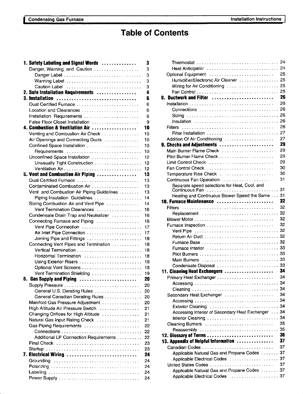
Table of Contents
1. Safety Labeling andSignalWords .............. 3
Danger, Warning and Caution .................. 3
Danger Label ............................... 3
Warning Label .............................. 3
Caution Label .............................. 3
2. Safe Installation Requirements ................ 4
3. Installation ................................ 6
Dual Certified Furnace ......................... 6
Location and Clearances ....................... 6
Installation Requirements ...................... 6
False Floor Closet Installation ................... 9
4. Combustion & Ventilation Air .................. 10
Venting and Combustion Air Check ............... 10
Air Openings and Connecting Ducts .............. 10
Confined Space Installation ..................... 10
Requirements ....................... . ...... 10
Unconfined Space Installation ................... 12
Unusually Tight Construction ................... 12
Ventilation Air ............................... 12
5. Vent and Combustion Air Piping ................ 13
Dual Certified Furnace ......................... 13
Contaminated Combustion Air ................... 13
Vent and Combustion Air Piping Guidelines ........ 13
Piping Insulation Guidelines ................... 14
Sizing Combustion Air and Vent Pipe ............. 14
Vent Termination Clearances .................. 16
Condensate Drain Trap and Neutralizer ........... 16
Connecting Furnace and Piping ................. 16
Vent Pipe Connection ........................ 17
Air Inlet Pipe Connection ...................... 17
Joining Pipe and Fittings ...................... 18
Connecting Vent Pipes and Termination ........... 18
Vertical Termination .......................... 18
Horizontal Termination ....................... 18
Using Extedor Risers ......................... 19
Optional Vent Screens ........................ 19
Vent Termination Shielding .................... 19
6. GasSupplyand Piping ....................... 20
Supply Pressure .............................. 20
General U.S. Derating Rules ................... 20
General Canadian Derating Rules ............... 20
Manifold Gas Pressure Adjustment ............... 20
High Altitude Air Pressure Switch ................ 21
Changing Orifices for High Altitude ............... 21
Natural Gas Input Rating Check ................. 21
Gas Piping Requirements ...................... 22
Connections ................................ 22
Additional LP Connection Requirements .......... 22
Final Check ................................. 23
Startup ..................................... 23
7. Electrical Wiring ............................ 24
Grounding .................................. 24
Polarizing ................................... 24
Labeling .................................... 24
Power Supply ................................ 24
Thermostat ................................. 24
Heat Anticipator ............................. 24
Optional Equipment .......................... 25
Humidifier/Electronic Air Cleaner ................ 25
Wiring for Air Conditioning ..................... 25
Fan Control ................................. 25
S. Ductwork and Filter ......................... 26
Installation .................................. 26
Connections ................................ 26
Sizing ..................................... 26
Insulation .................................. 26
Filters ..................................... 26
Filter Installation ............................. 27
Addition Of Air Conditioning .................... 27
9. Checks and Adjustments ...................... 2g
Main Burner Flame Check ..................... 29
Pilot Burner Flame Check ...................... 29
Limit Control Check .......................... 29
Fan Control Check ........................... 30
Temperature Rise Check ...................... 30
Continuous Fan Operation ..................... 31
Separate speed selections for Heat, Cool, and
Continuous Fan ............................. 31
Heating and Continuous BLower Speed the Same ... 31
10. Furnace Maintenance ....................... 32
Filters ..................................... 32
Replacement ............................... 32
Blower Motor ................................ 32
Furnace Inspection ........................... 32
Vent Pipe .................................. 32
Return Air Duct .............................. 32
Furnace Base ............................... 32
Furnace Intedor ............................. 33
Pilot Burners ................................ 33
Main Burners ............................... 33
Condensate Disposal ......................... 33
11. CleaningHeat Exchangers.................... 34
Primary Heat Exchanger ....................... 34
Accessing .................................. 34
Cleaning ................................... 34
Secondary Heat Exchanger .................... 34
Accessing .................................. 34
Extedor Cleaning ............................ 34
Accessing Intedor of Secondary Heat Exchanger ... 34
Interior Cleaning ............................. 34
Cleaning Burners ............................ 35
Reassembly ................................ 35
12. Glossary of Terms ........................... 36
13. Appendix of Helpful Information ............... 37
Canadian Codes ............................. 37
Applicable Natural Gas and Propane Codes ....... 37
Applicable Electrical Codes .................... 37
United States Codes .......................... 37
Applicable Natural Gas and Propane Codes ....... 37
Applicable Electrical Codes .................... 37
Page 3
I.Condensing Gas Furnace
1, SafetyLabelingandSi0nalWords
Installation Instructions I
Danger,Warning and Caution
The signal words DANGER, WARNING and CAUTION are used to identify levels of hazard seriousness. The signal word
DANGER isonly used on product labels to signify an immediate hazard. The signal words WARNING and CAUTION will
be used on product labels and throughout this manual and other manuals that may apply to the product.
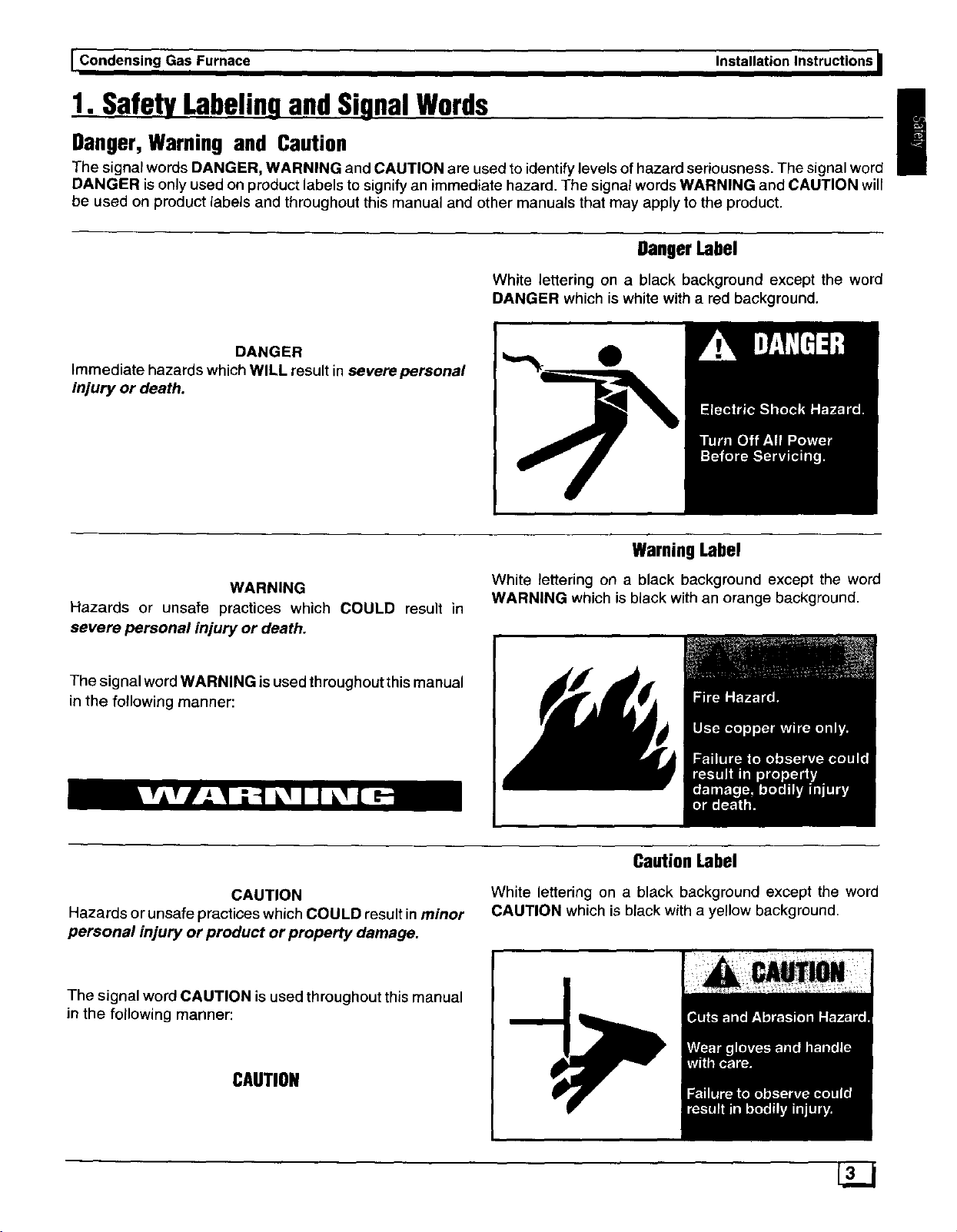
DangerLabel
White lettering on a black background except the word
DANGER which is white with a red background.
DANGER
Immediate hazards which WILL result in severe personal
injury or death.
WarningLabel
WARNING
Hazards or unsafe practices which COULD result in
severe personal injury or death.
White _ettering on a black background except the word
WARNING which is black with an orange background.
!
The signal word WARNING is used throughout this manual
in the following manner:
CAUTION
Hazards or unsafe practices which COULD result in minor
personal injury or product or property damage.
The signal word CAUTION is used throughout this manual
in the following manner:
CAUTION
CautionLabel
White lettering on a black background except the word
CAUTION which is black with a yellow background.
Page 4
_ Installation Instructions Condensin_l Gas Furnace I
2. SafeInstallationRequirements
Installation or repairs made by unqualified
persons can result in hazards to you and others.
Installation MUST conform with local codes or, in
the absence of local codes, with codes of the
country having jurisdiction. See Appendix.
The information contained in this manual is
intended for use by a qualified service technician
familiar with safety procedures and equipped
with the proper tools and test instruments.
Failure to carefully read and follow all instruc-
tions in this manual can result in furnace
malfunction, property damage, personal injury
and/or death.
NOTE: This furnace is design certified by the American
Gas Association and the Canadian Gas Association for in-
stallation in the United States and Canada. Refer to the ap-
propriate codes, along with this manual, for proper
installation.
• This furnace is NOT approved for installation in
mobile homes, trailers or recreation vehicles.
• Do NOT use this furnace as a construction heater.
• Use only the Type of gas approved for this furnace
(see Rating Plate on unit). Overfiring will result in
failure of heat exchanger and cause dangerous op-
eration.
• Ensure adequate combustion and ventilation air is
provided to the furnace.
• Seal supply and return air ducts.
• The vent system MUST be checked to determine that
it is the correct type and size.
• Install correct filter type and size.
• Unit MUST be installed so electrical components are
protected from direct contact with water.
NOTE; It is the personal responsibility and obligation of the
customer to contact a qualified installer to ensure that the
installation is adequate and conforms to governing codes
and ordinances.
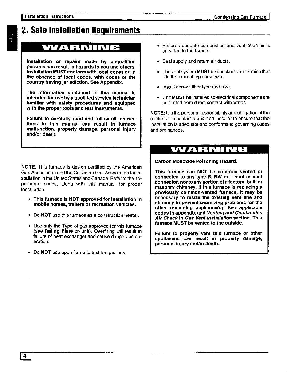
Carbon Monoxide Poisoning Hazard.
This furnace can NOT be common vented or
connected to any type B, BW or L vent or vent
connector, nor to any portion of a factory-built or
masonry chimney. If this furnace is replacing a
previously common-vented furnace, it may be
necessary to resize the existing vent line and
chimney to prevent oversizing problems for the
other remaining appliance(s). See applicable
codes in appendix and Venting and Combustion
Air Check in Gas Vent Installation section. This
furnace MUST be vented to the outside.
Failure to properly vent this furnace or other
appliances can result in property damage,
personal injury and/or death.
• Do NOT use open flame to test for gas leak.
Page 5
I Condensing Gas Furnace
installation Instructions
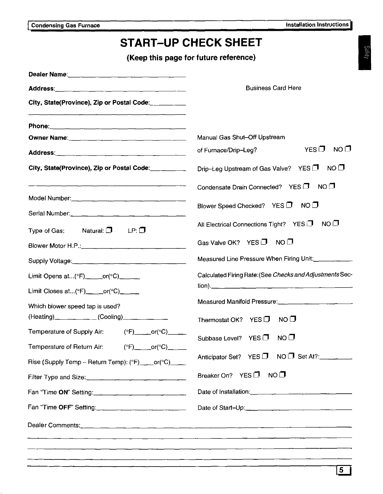
START-UP CHECK SHEET
(Keep this page for future reference)
Dealer Name:
Address:
City, State(Province), Zip or Postal Code:
Phone:
Owner Name:
Address:
City, State(Province), Zip or Postal Code:
Model Number:
Serial Number:.
Type of Gas: Natural: [_1 LP: _1
Business Card Here
Manual Gas Shut-Off Upstream
of Furnace/Drip-Leg?
Drip-Leg Upstream of Gas Valve?
Condensate Drain Connected? YES _1 NO [_
Blower Speed Checked? YES CI NO [_1
All Electrical Connections Tight? YES _1 NO {_1
YES 1_1 NO [_1
YES {_1 NO _1
!
Blower Motor H.P.:
Supply Voltage:.
Limit Opens at...(°F) or(°C)__
Limit Closes at...(°F) or(°C).__
Which blower speed tap is used?
(Heating). (Cooling)
Temperature of Supply Air: (°F) or(°C).__
Temperature of Return Air: (°F)__. or(°C).__
Rise (Supply Temp - Return Temp): (°F) or(°C)__
Filter Type and Size:
Fan "Time ON" Setting:.
Fan 'q'ime OFF" Setting:
Gas Valve OK? YES CI NO[_I
Measured Line Pressure When Firing Unit:
Calculated Firing Rate:(See ChecksandAdjustmentsSec-
tion).
Measured Manifold Pressure:
Thermostat OK?
Subbase Level?
Anticipator Set?
Breaker On? YES [_1
Date of Installation:
Date of Start-Up:
YES O NO
YESI_I NOel
YES_I NO _1 Set At?:
NO _1
Dealer Comments:
Page 6
_ Installation Instructions Condensin_l Gas Furnace I
3. Installation
!
NOTE: Installation MUST conform with local building
codes and local plumbing and waste water codes, or inthe
absence of local codes, with codes of the country having
jurisdiction. See Appendix.
DualCertified Furnace
This furnace is dual certified. This means that the INLET
pipe is optional. See Figure "1for identification of INLET
and OUTLET pipe. Combustion air can be drawn from out-
side the structure or inside the structure. If drawing com-
bustion air from inside the structure, adequate make up air
MUST be provided to compensate for oxygen burned. See
Confined Space Installation in the Combustion and
Ventilation Air chapter.
LocationandClearances
1. Referto Figure 1 fortypicaldirectventornon_:lirect
vent installation and basicconnecting parts required.
Supply and return air plenums and duct are also re-
quired.
2.
If furnace is a replacement, it is usually best to install
the furnace where the old one was. Choose the loca-
tion or evaluate the existing location based upon the
minimum clearance and furnace dimensions
(Figure 2).
Installation Requirements
1. Install furnace level.
2. This furnace is NOT to be used for temporary heat of
buildings or structures under construction.
3. Install furnace as centralized as practical with re-
spect to the heat distribution system.
4. Install the vent pipes as short as practical. (See Vent
and Combustion Air Piping section).
5. Maintain clearance for fire safety and servicing. A
front clearance of 30" (762mm) is recommended for
access to the burner, controls and filter.
CAUTION
Special precautions MUST be made if installing
furnace in an area which may drop below freezing.
This can cause improper operation or damage to
equipment. If furnace environment has the potential of
freezing, the drain trap and blower must be protected
with antifreeze. Disconnect the rubber coupling on top
of furnace and pour 8 onces of sanitary type (RV)
antifreeze into the vent pipe to protect the blower and
drain trap from freeze damage.
Do NOT operate furnace in a contaminated
atmosphere containing chlorine, fluorine or any other
damaging chemicals. Refer to Combustion &
Ventilation Air section, Contaminated Combustion
Air,
6. Use a raised base if the floor is damp or wet at times.
7. Residential garage installationsrequire:
• Burners and ignition sources installed at least 18
inches(457mm) above the floor.
• Located or physically protected from possible dam-
age by a vehicle.
61ZJ
Page 7
I Condensing Gas Furnace Installation Instructions
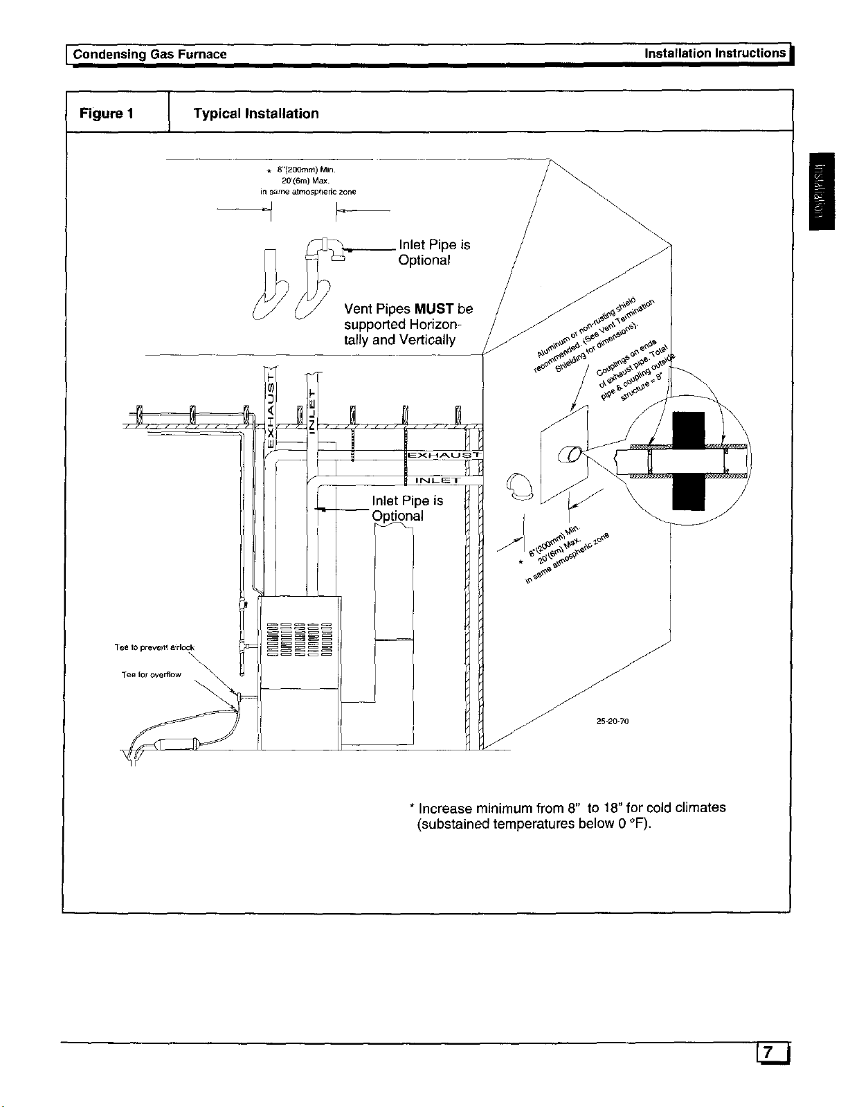
Figure I Typical Installation
* 8"(200ram) Min.
20'(6m) Max.
in same atmospheric zone
--q
ipe is
Optional
Vent Pipes MUST be
supported Horizon-
tally and Vertically
!
Tee to prevellt a_rlc<tk
Tee for overflow
I NLE:T
Inlet Pipe is
\
* Increase minimum from 8" to 18" for cold climates
(substained temperatures below 0 °F),
7LZ.J
Page 8
_ Installation Instructions Condensin_lGas Furnace J
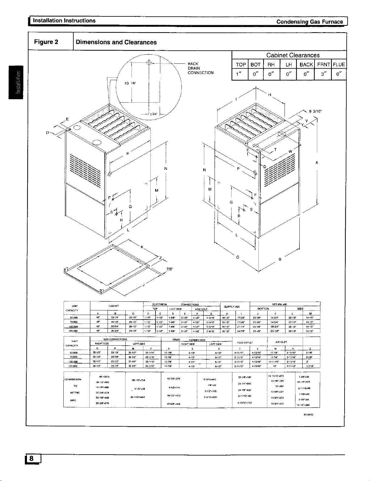
Figure 2 Dimensions and Clearances
|
I' 10 7_"
\
BACK
DRAIN
CONNECTION
Cabinet Clearances
TOP BOT RH LH BACK FRNT FLUE
1" 0 0 0 0" 3 0"
93/16.
A
L
U_IT
CAPACPTY
S00CO
7SCO0
_00.000
125CC_
_O
/CONWnSION
G,_S¢ON_ECTIO_S ORAIN CONNE¢ n_
AIG_T SIDE L_" SIO_ RdGH_SlOE
N I P N _, n s
t/2" i 2_-_B" :_,___- _.1_16. t _,_- 4._t_
i
ze 1_"=724
lt2-=$s
1o 7_.=_76
_.1F_=_7o
LEm" SlO_
S • V
7r_-_
c
nETURNApR
_)TTOM SIDE
J L I M
2_.tm. 23 IFZ" 22.1_2" I _ lrZ"
_LUE O,_TL_T
_" 2 _I_S" _.7_16_
231_'_7
14_'_'=375 2.V_.=S 4
2_._
Page 9
I Condensing Gas Furnace
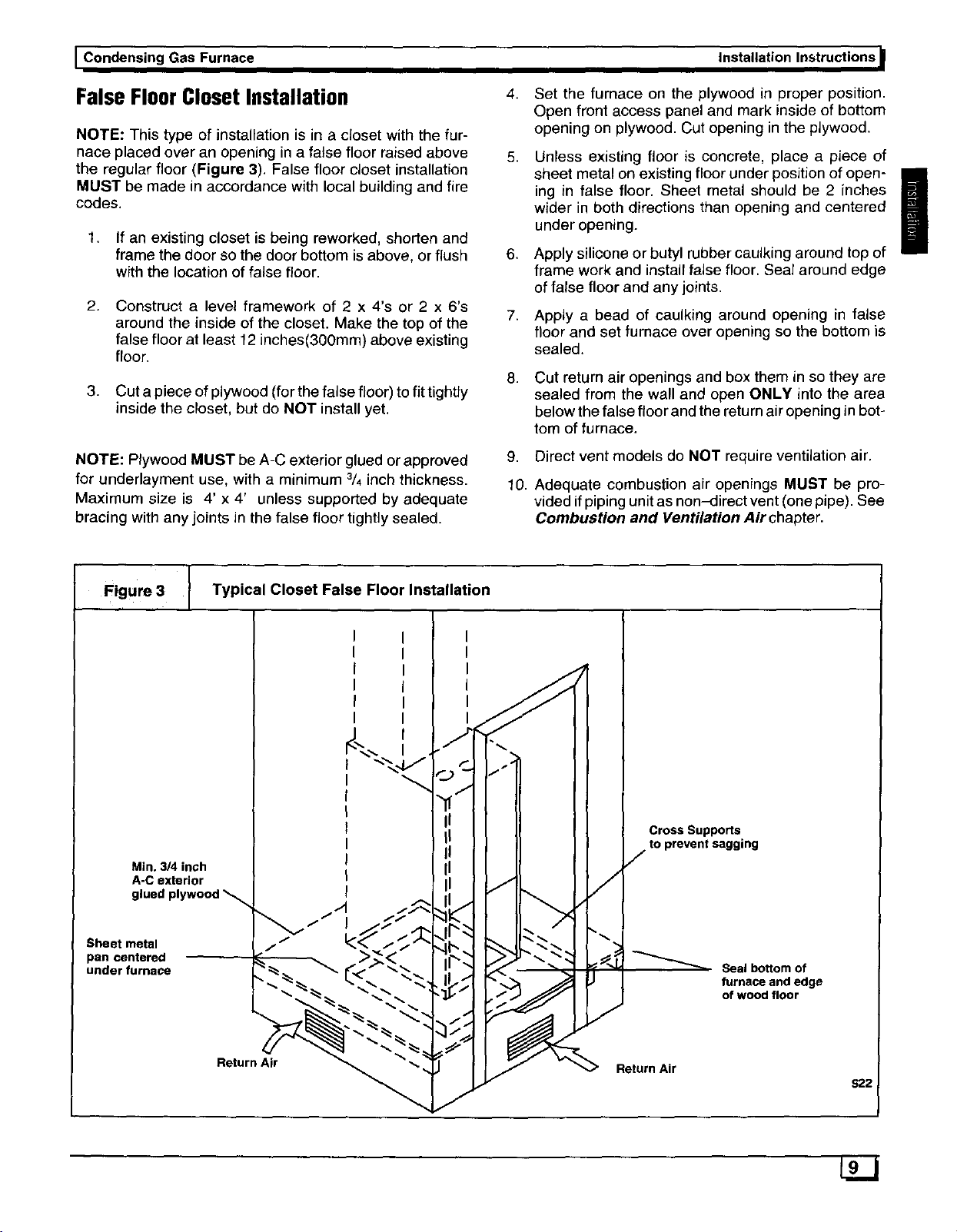
False FloorClosetInstallation
NOTE: This type of installation is in a closet with the fur-
nace placed over an opening in a false floor raised above
the regular floor (Figure 3). False floor closet installation
MUST be made in accordance with local building and fire
codes.
1. If an existing closet is being reworked, shorten and
frame the door so the door bottom is above, or flush
with the location of false floor.
2. Construct a level framework of 2 x 4's or 2 x 6's
around the inside of the closet. Make the top of the
false floor at least 12 inches(30Omm) above existing
floor.
3. Cut a piece of plywood (for the false floor) to fit tightly
inside the closet, but do NOT install yet.
NOTE: Plywood MUST be A-C exterior glued or approved
for underlayment use, with a minimum 3/4inch thickness.
Maximum size is 4' x 4' unless supported by adequate
bracing with any joints in the false floor tightly sealed.
Installation Instructions I
4.
Set the furnace on the plywood in proper position.
Open front access panel and mark inside of bottom
opening on plywood. Cut opening in the plywood.
5,
Unless existing floor is concrete, place a piece of
sheet metal on existing floor under position of open-
ing in false floor. Sheet metal should be 2 inches
wider in both directions than opening and centered
under opening.
6,
Apply silicone or butyl rubber caulking around top of
frame work and install false floor. Seal around edge
of false floor and any joints.
7,
Apply a bead of caulking around opening in false
floor and set furnace over opening so the bottom is
sealed.
8.
Cut return air openings and box them in so they are
sealed from the wall and open ONLY into the area
below the false floor and the return air opening in bot-
tom of furnace.
g,
Direct vent models de NOT require ventilation air.
10.
Adequate combustion air openings MUST be pro-
vided if piping unit as non-direct vent (one pipe). See
Combustion and Ventilation Air chapter.
|
Figure3 I Typical Closet False Floor Installation
Min. 3/4 inch
A-C exterior
glued plywood
Sheet metal
pan centered
under furnace
J
Cross Supports
to prevent sagging
Seal bottom of
furnace and edge
of wood floor
Return Air
Return Air
S22
Page 10
I Installation Instructions Condensin_lGas Furnace J
4. Combustion& VentilationAir
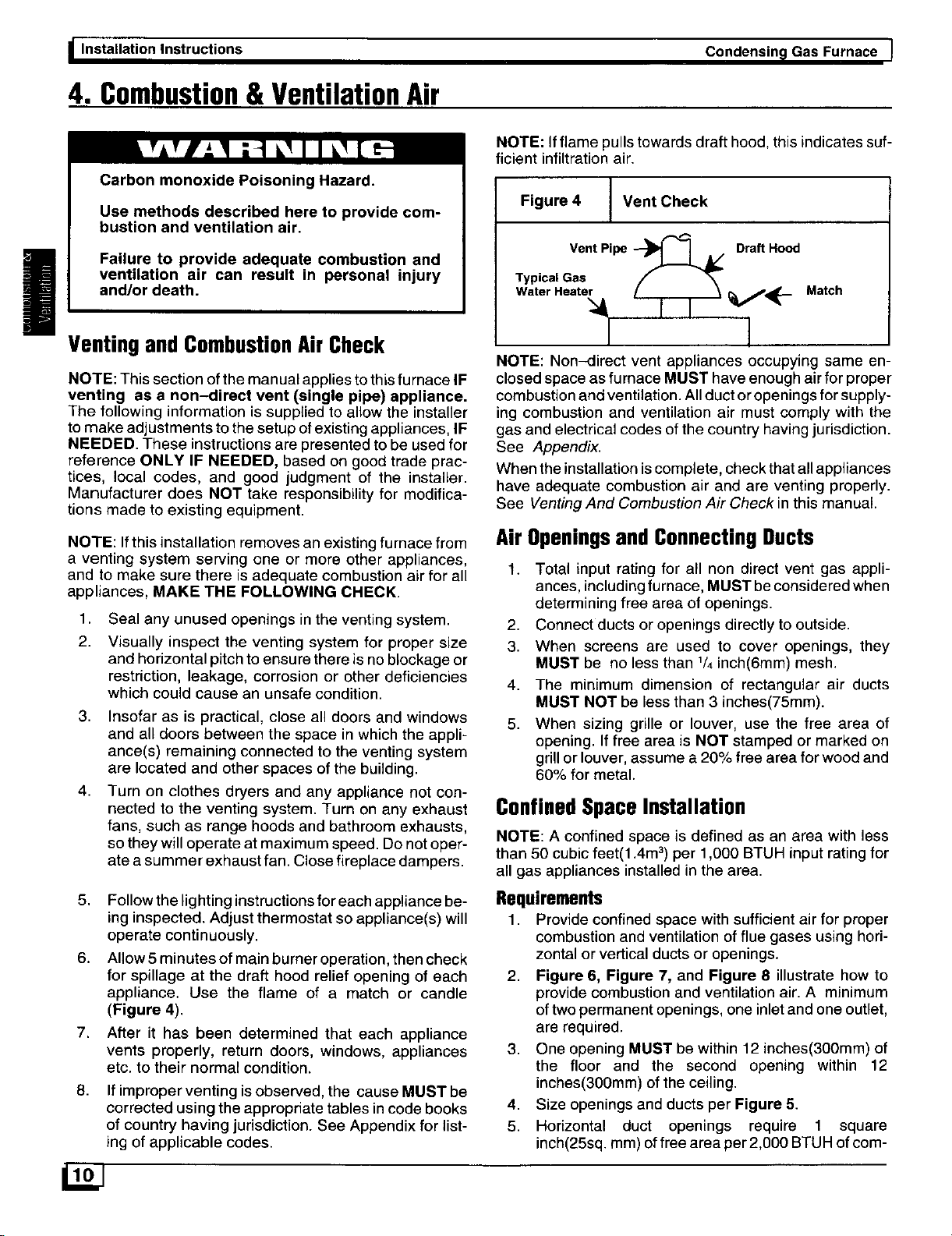
NOTE: Ifflame pulls towards draft hood, this indicates suf-
ficient infiltration air.
Carbon monoxide Poisoning Hazard.
Use methods described here to provide com-
bustion and ventilation air.
Figure 4 _ Vent Check
Failure to provide adequate combustion and
ventilation air can result in personal injury
and/or death.
!
VentingandCombustionAir Check
NOTE: This section ofthe manual applies to this furnace IF
venting as a non-direct vent (single pipe) appliance.
The following information is supp[iedto allow the installer
to make adjustments to the setup ofexisting appliances, IF
NEEDED. These instructions are presented to be used for
reference ONLY IF NEEDED, based on good trade prac-
tices, local codes, and good judgment of the installer.
Manufacturer does NOT take responsibility for modifica-
tions made to existing equipment.
NOTE: If this installation removes an existing furnace from
a venting system serving one or more other appliances,
and to make sure there is adequate combustion air for all
appliances, MAKE THE FOLLOWING CHECK.
1,
Seal any unused openings in the venting system.
2.
Visually inspect the venting system for proper size
and horizontal pitch to ensure there is no blockage or
restriction, leakage, corrosion or other deficiencies
which could cause an unsafe condition.
3. Insofar as is practical, close all doors and windows
and all doors between the space in which the appli-
ance(s) remaining connected to the venting system
are located and other spaces of the building.
4. Turn on clothes dryers and any appliance not con-
nected to the venting system. Turn on any exhaust
fans, such as range hoods and bathroom exhausts,
so they will operate at maximum speed. Do not oper-
ate asummer exhaust fan. Close fireplace dampers.
Vent Pipe --_1 I A/ DraftHood
Typical Gas
Water Heate_l_l _ _,P_._ Match
NOTE: Non-direct vent appliances occupying same en-
closed space as furnace MUST have enough air for proper
combustion and ventilation. All duct or openings for supply-
ing combustion and ventilation air must comply with the
gas and electrical codes of the country having jurisdiction.
See Appendix.
When the installation is complete, check that all appliances
have adequate combustion air and are venting properly.
See Venting And Combustion Air Check in this manual.
Air Openingsand Connecting Ducts
1. Total input rating for all non direct vent gas appli-
ances, includingfurnace, MUST be considered when
determining free area of openings.
2. Connect ducts or openings directly to outside.
3. When screens are used to cover openings, they
MUST be no less than 1/4inch(6mm) mesh.
4. The minimum dimension of rectangular air ducts
MUST NOT be less than 3 inches(75mm).
5. When sizing grille or louver, use the free area of
opening. If free area is NOT stamped or marked on
grillor louver, assume a 20% free area for wood and
60% for metal.
ConfinedSpaceInstallation
NOTE: A confined space is defined as an area with less
than 50 cubic feet(1.4m 3)per 1,000 BTUH input rating for
all gas appliances installed in the area.
5. Follow the lighting instructions for each appliance be-
ing inspected. Adjust thermostat so appliance(s) will
operate continuously.
6. Allow 5 minutes of main burner operation, then check
for spillage at the draft hood relief opening of each
appliance. Use the flame of a match or candle
(Figure 4).
7,
After it has been determined that each appliance
vents properly, return doors, windows, appliances
etc. to their normal condition.
8.
If improper venting is observed, the cause MUST be
corrected using the appropriate tables in code books
of country having jurisdiction. See Appendix for list-
ing of applicable codes.
Requirements
1. Provide confined space with sufficient air for proper
combustion and ventilation of flue gases using hori-
zontal or vertical ducts or openings.
2. Figure 6, Figure 7, and Figure 8 illustrate how to
provide combustionand ventilation air. A minimum
of two permanent openings, one inletand one outlet,
are required.
3. One opening MUST be within 12 inches(300mm) of
the floor and the second opening within 12
inches(300mm) of the ceiling.
4. Size openings and ducts per Figure 5.
5. Horizontal duct openings require 1 square
inch(25sq, mm) offree area per 2,000 BTUH ofcorn-
Page 11
I Condensing Gas Furnace
Installation Instructions
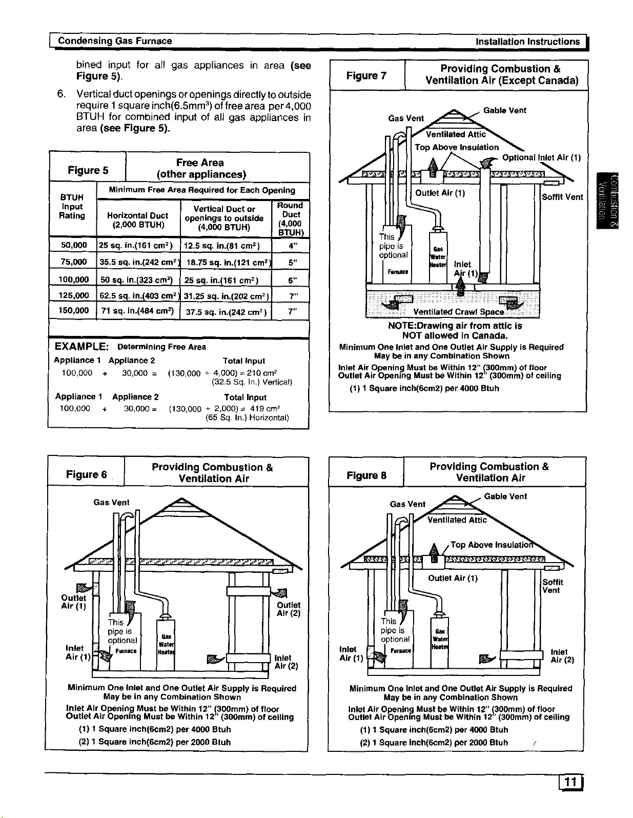
bined input for all gas appliances in area (see
Figure 5).
,
Vertical duct openings or openings directly to outside
require I square inch(6.Smm 3)of free area per 4,000
BTUH for combined input of all gas appliances in
area (see Figure 5).
Free Area
Figure 5
STUH
Input
Rating
50,000
75,000
100,000
. 125,000
150,000
Minimum Free Area Required for Each Opening
Horizontal Duct
(2,000 BTUH)
25 sq. in.(161 cm 2)
35.5 aq. in.(242 cm 2
50 sq. in.(323 cm2I
62.5 sq. in.(403 cm z
71 sq. in.(484 cm 2)
(other appliances)
Vertical Duct or
openings to outside
(4,000 BTUH)
12.5 sq, in.(81 em2)
15.75 sq. in.(121 cm 2
25 sq. in.!161 cm 2)
31.25 sq. in.(202 cm2)
37.5 sq. in.(242 cm 2)
EXAMPLE: Determining Free Area
Appliance 1 Appliance 2 Total Input
100,000 + 30,000 = (130,000 + 4,000) 2210cm 2
Appliance 1 Appliance 2 Total Input
100,000 + 30,000= (130,000 + 2,000)= 4tgcm 2
(32.5 Sq. In.) Vertical)
(65 Sq. In.) Horizontal)
Round
Duct
(4,000
BTUH I
4"
5-
6 _
7"
7,,
Figure 7
Gas Vent
NOTE:Drawing air from attic is
NOT allowed in Canada.
Minimum One Inlet and One Outlet Air Supply is Required
May be in any Combination Shown
Inlet Air Opening Must be Within 12" (3O0mm) of floor
Outlet Air Opening Must be Within 12" (300mm) of ceiling
(1) 1 Square ineh(6cm2) per 4000 Btuh
Providing Combustion &
Ventilation Air (Except Canada)
Soffit Vent
(1)
!
I Providing Combustion &Figure 6 Ventilation Air
Gas Vent
f
Outlet
Air (1) Outlet
tn II liAr'2'
I Ilpels I I_-I II It
ptional
Air (1) _ilre_2)
Minimum One Inlet and One Outlet Air Supply is Required
Inlet Air Opening Must be Within 12" 130Omm) of floor
Outlet Air Opening Must be Within 12 (300ram) of ceiling
May be in any Combination Shown
(1) 1 Square inch(6cm2) per 4000 Btuh
(2) 1 Square inch(6cm2) per 2000 atuh
Figure 8 Ventilation Air
Minimum One Inlet and One Outlet Air Supply is Required
Inlet Air Opening Must be Within 12" 1,300mm) of floor
Outlet Air Opening Must be Within 12 (300ram) of ceiling
(1) 1 Square inch(6cm2) per 4000 Btuh
(2) 1 Square inch(6cm2) per 2000 Btuh r
I Providing Combustion &
Gas Vent _ Gable Vent
Ventilated Attic_
Top Above Insulatioif_
t Air (1) ! Soffit
I Vent
May be in any Combination Shown
Page 12
I Installation Instructions
Condensing]Gas Furnace I
!
Unconfined SpaceInstallation
Carbon Monoxide Poisoning Hazard.
Most homes will require additional air,
An unconfined space or homes with tight con-
struction may not have adequate air infiltration
for proper combustion and ventilation of flue
gases,
Failure to supply additional air by means of venti-
lation grilles or ducts could result in personal in-
jury and/or death•
An unconfined space is defined as an area having a mini-
mum volume of 50 cubic feet(1.4m 3)per 1,000 Btuh total
input rating for all gas appliances in area. Refer to Figu re 9
for minimum area required.
NOTE: Refer to definitions in section titled Unusually Tight
Construction and the Appendix. If any one of the conditions
apply, the space MUST be considered confined space re-
gardless of size.
1. Adjoining rooms can be considered part of an uncon-
fined area if there are openings without doors be-
tween rooms.
2,
An attic or crawlspace may be considered an uncon-
fined space provided there are adequate ventilation
openings directly to outdoors. Openings MUST re-
main open and NOT have any means of being closed
off. Ventilation openings to outdoors MUST be at
least 1 square inch(25mm 2) of free area per 4,000
BTUH of total input rating for all gas appliances in
area.
4. Air inlet MUST be screened with not less than 1/4
inch(6mm) mesh screen.
UnusuallyTightConstruction
In unconfined spaces, infiltration may be adequate to pro-
vide air for combustion, ventilation and dilution of flue
gases. However, in buildings with unusually tight construc-
tion, additional air MUST be provided using the methods
described in section titled Confined Space Installation:
If any one of the following conditions are present, the
space MUST be treated as confined space.
1. Walls and ceilings exposed to the outside have a
continuous, sealed vapour barrier. Openings are
gasketed or sealed.
2. Doors and openable windows are weather stripped.
3,
Other openings are caulked or sealed. These include
joints around window and door frames, between sole
plates and floors, between wall-ceiling joints, be-
tween wall panels, at penetrations for plumbing,
electrical and gas lines, etc.
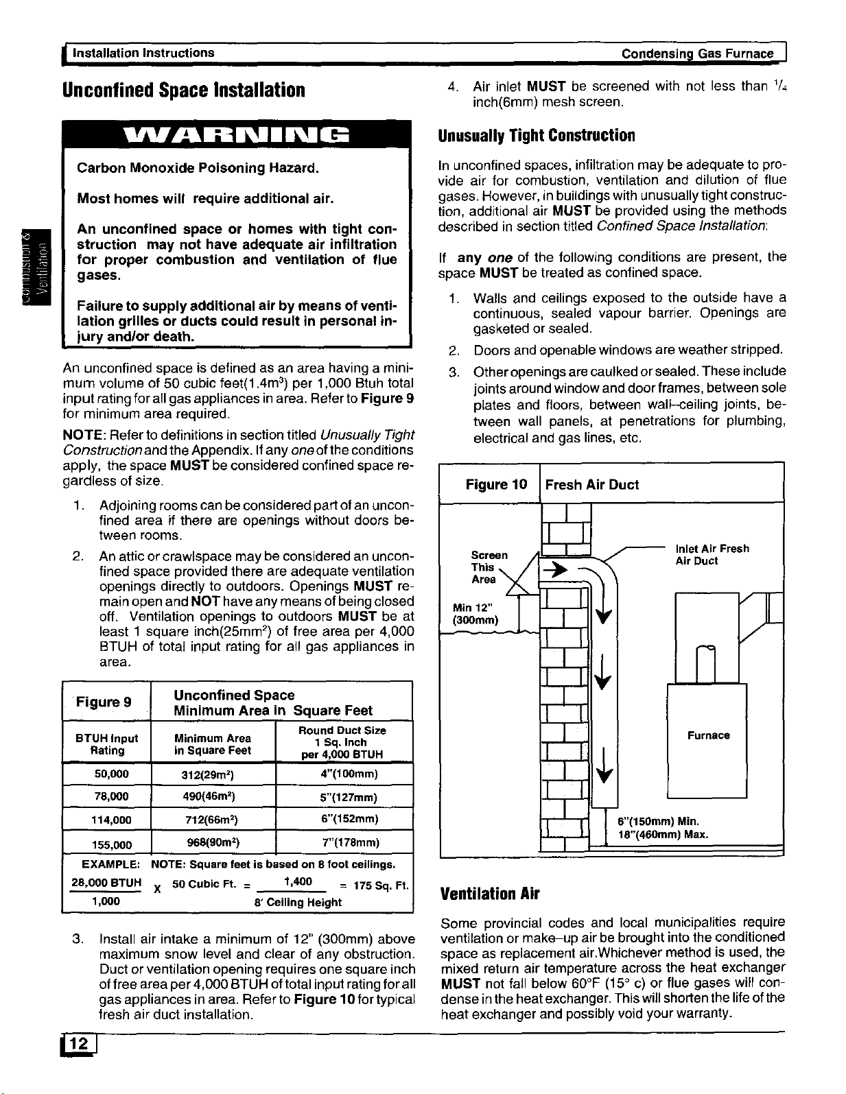
Figure 10
Screen /
Area
This _,_
Min 12" /
Fresh Air Duct
F Inlet Air Fresh
f
Air Duct
Figure 9 Unconfined Space
BTUH Input Minimum Area 1 Sq. Inch
Rating in Square Feet per 4,000 BTUH
50,000 312(29m 2) 4"(100ram)
78,000 490(46m 2) 5"(127mm)
114,000 712(66m _) 6"(152m m)
155,000 968(90m=) T'(178m m)
EXAMPLE: NOTE: Square feet is based on 8 foot ceilings,
28,000 BTUH X 50 Cubic Ft. = 1,400 -- 175 Sq. Ft.
1,000 8' Ceiling Height
3.
Install air intake a minimum of 12" (300mm) above
maximum snow level and clear of any obstruction.
Duct or ventilation opening requires one square inch
of free area per 4,000 BTUH of total input rating for all
gas appliances in area. Refer to Figure 10 for typical
fresh air duct installation.
Minimum Area in Square Feet
Round Duct Size
Furnace
6"(150mm) Min.
18"(460mm) Max.
Ventilation Air
Some provincial codes and local municipalities require
ventilation or make-up air be brought into the conditioned
space as replacement air.Whichever method is used, the
mixed return air temperature across the heat exchanger
MUST not fall below 60°F (15° c) or flue gases will con-
dense in the heat exchanger. This will shorten the life of the
heat exchanger and possibly void your warranty.
Page 13

Condensing Gas Furnace
5. VentandCombustionAirPiping
Carbon monoxide poisoning, fire and explosion
hazard.
Read and follow all instructions in this section
Failure to properly vent this furnace can result in
property damage, personal injury and/or death.
DualCertified Furnace
Installation Instructions,
• Carbon tetrachtoride.
• Halogen type refrigerants.
• Cleaning solvents (such as perchloroethylene).
• Printing inks, paint removers, varnishes, etc..
• Hydrochloric acid.
• Sulfuric Acid.
• Solvent cements and glues.
• Antistatic fabric softeners for clothes dryers.
• Masonry acid washing materials.
This furnace is certified as a category IV appliance and is
dual certified as a direct vent furnace using outside air for
combustion or it can use air from inside the structure for
combustion. The INLET air pipe is optional. If combustion
air comes from inside the structure, adequate make up air
MUST be provided to compensate for oxygen burned. See
Confined Space Installation in the Combustion and
Ventilation Air chapter. If combustion air is drawn from
outside the structure, it MUST be taken from the same at-
mospheric pressure zone as the vent pipe.
ContaminatedCombustionAir
Installations in certain areas or types of structures will in-
crease the exposure to chemicals or Halogens which may
harm the furnace.
The following areas or types of structures may contain
chemicals or Halogens. Inspect structure carefully to en-
sure listed chemicals or substances are NOT present.
• Commercial buildings.
• Buildings with indoorpools.
• Furnaces installed in laundry rooms.
• Furnaces installed in hobby or craft rooms.
• Furnaces installed near chemical storage areas.
Exposing the furnace to the following substances will dam-
age the furnace. Do NOT situate air inlet near any of the
following chemicals or their source.
CAUTION
Terminate the combustion air intake as far as possible
from any air conditioner, heat pump, swimming pool,
swimming pool pumping, chorlinator or filtration
units, or dryer vent.
• Permanent wave solutions for hair.
• Chlorinated waxes and cleaners.
• Chlorine based swimming pool chemicals.
• Water softening chemicals.
• De-icing salts or chemicals.
Vent andCombustionAirPipingGuidelines
!
NOTE: All vent piping MUST be installed in compliance
with local codes or ordinances, these instructions, good
trade practices, and codes of country having jurisdiction.
1. Determine the best routing and termination for the
vent pipe and air inlet pipe (when used) by referring
to all of the instructions and guidelines in Section 6.
2. Determine the size required for the vent pipe and air
inlet pipe (when used).
3. Looselyassemble allventing parts without adhesive
(pipe joint cement) for correct fit before final assem-
bly.
4. Use of vertical piping is preferred because there will
be some moisture in the flue gases that may con-
dense as it leaves the vent pipe (See Special Instruc-
tion For Horizontal Vents),
5. The vent MUST exit the furnace at the top left side.
6. The vertical vent pipe MUST be supported so that no
weight is allowed to rest on the combustion blower.
7. Exhaust vent piping diameter MUST NOT be re-
duced.
8. All piping from the furnace to termination MUST
slope upwards, away from furnace, a minimum of
U4" per foot of run (6mm per 300mm).
9. Use DWV type long radius elbows whenever possi-
ble, as they provide for the minimum slope on hori-
zontal runs and they provide less resistance in the
vent system. If DWV elbows cannot be used, use
two, 45 degree elbows when possible. On horizontal
runs the elbows can be slightly misaligned to provide
the correct slope.
10. All horizontal pipe runs MUST be supported at least
every five feet with metal pipe strapping. NO sags or
dips are permitted.
11. All vertical pipe runs MUST be supported every six
feet where accessible.
12. The maximum pipe length is40 total feet (12m) in the
inlet or outlet side of the system. Up to five, 90 de-
gree elbows can be used on the inlet orthe outlet,
(See Vent Tables).
13. The minimum pipe run length is 5 feet (1.5m).
14. Venting thr°ugh acrawl space is permitted °nly as di-
rected by your distributor or factory representative.
Page 14

Condensing Gas Furnace Installation Instructions
15.
The piping can be run in the same chase or adjacent
to supply or vent pipe for water supply or waste
plumbing. Itcan also be run in the same chase with a
vent from another 90+ furnace.
NOTE: In NO case can the piping be run in a chase
where temperatures can exceed 140° F. or where ra-
diated heat from adjacent surfaces would exceed
140° F.
16. If installing as a direct-vent appliance, the vent outlet
MUST be installed to terminate in the same atmos-
pheric pressure zone as the combustion air inlet.
17. The vent system can be installed in an existing un-
used chimney provided that:
Both the exhaust vent and air intake run the length of
the chimney.
No other gas fired appliance or fireplace is vented
into the chimney.
The top of the chimney MUST be sealed flush or
crowned up to seal against rain or melting snow so
ONLY the piping protrudes.
• The termination clearances shown in Figure 16 are
maintained.
Piping Insulation Guidelines
NOTE: In general, chimneys on an outside wall and attics
are exposed to cold conditions which can cause the vent
pipe to sweat from condensation. This can lead to moisture
damage to living spaces. It is highly recommended that pip-
ing in these cases be insulated to insure proper protection
from condensation damage.
Use 1/2" (50mm) wall, closed cell, neoprene insulation or
equivalent. If Fiberglas or equivalent insulation is used it
must have a vapor barrier. Use Rvalues of 7 up to 10 feet,
R-11 ifexposure exceeds 10 feet. If Fiberglas insulation is
used, exterior to the structure, the pipe MUST be boxed in
and sealed against moisture.
1. Insulate pipe when the exhaust vent passes through
an unconditioned space or raceway.
2. If situations require pipe to be run on the exterior wall
to reach a suitable termination point, it MUST be
properly insulated.
3. If it is necessary to insulate piping when an inactive
chimney is used as a chase, the top of the chimney
MUST be sealed flush or crowned up to seal against
rain or melting snow so ONLY the piping protrudes.
4. When the vent or combustion air pipe height above
the roof exceeds 30 inches(760mm), or if an exterior
vertical riser is used on a horizontal vent to get above
snow levels, the exterior portion MUST be insulated.
5. When combustion air inlet piping is installed above a
suspended ceiling, the pipe MUST be insulated with
moisture resistant insulation such as Armaflex or
other equivalent type of insulation.
6. Insulate combustion air inlet piping when run in
warm, humid spaces such as basements.
SizingCombustionAirandVentPipe
1. Single Pipelnstallation-lf installing as anon-direct
vent appliance, (single outlet pipe and no inlet pipe)
refer to Table 1. The table shows the maximum
number of elbows allowed with any given pipe di-
ameter and length of run.
2. Double Pipe Installation-If installing as a direct-
vent appliance, consult Table 2 to select the proper
diameter exhaust and combustion air piping. Ex-
haust and combustion air piping is sized for each fur-
nace Btuh size based on total lineal vent length (on
inlet or outlet side), and number of 90° elbows re-
quired.
3. Use of Elbows-Two 45 ° elbows can be substituted
for one 90° elbow. The elbow or elbows used for vent
termination outside the structure ARE counted, in-
cluding elbows needed to bring termination above
expected snow levels. When the vent system
length used is borderline with the next size com-
bination category, always use the next larger
size.
EXAMPLE: Refer to, 75,000 Btuh Furnace, Table 2.
• A vent system uses 25 feet of Inlet pipe and 24 feet
of Outlet pipe. Use the maximum length found in your
system, so 25 ft. is the lengthto use in these tables. The
25-30 column should be used.
• There are 4 elbows on the Outlet and 2 elbows on the
Inlet. Use the 4 elbows row because that is the maxi-
mum number of elbows on any one side (Inlet or Ex-
haust).
• In this example, combinations C or F are allowed.
Using the legend at the bottom of the table, combination
C is 3" Inlet with a 21/2" Exhaust. Combination F is a 3"
Inlet with a 3" Exhaust. Either combination is allowed to-
gether, but they can NOT be mixed. Inother words, part
of a C combination can NOT be used with part of an F
combination just because they are listed together in the
same block.
Page 15

J Condensing Gas Furnace Installation Instructions
Pipe Diameter Table
Table I Single Piping ONLY
50,000 & 75,000 Btuh Furnaces
Max No. Of
Elbows in One
Side3
UP TO 5 All combinations use "A" a 2" Exhaust
Max No. Of Feet of Pipe*
Elbows in One
Side _ 0-9 10-14 15-1 €. 20-24 25-29 30-3_ 35-40
1 A A A A A A B,C
2 A A A A A B,C B,C
3 A A A A B,C B,C B,C
4 A A A B,C B,C B,C B,C
5 A A B,C B,C B,C B,C B,C
Max No. Of Feet of Pipe*
Elbows in One
Side _ 0-9 10-14 15-19 20-24 25-2_ 30-3, 35-4(_
1 A A B,C B,C B,C B,C C
0-,1,0-t,lt5-,o120-2,125-,930- 3 0
100,000 Btuh Furnace
125 000 Btuh Furnace
Feet of Pipe*
Table 2 Pipe Diameter Table
50,000 Btuh Furnace
Max No. Of Feet of Pipe*
Side _ 0-9 10-14 15-19 20-24 25-29 30-3 35-4(
E,hows,oonsI I I I
UP TO 5 All combinations use "A" a 2" Exhaust
Max No. Of Feet of Pipe*
Elbows in One
Side _ 0-9 10-14 15-19 20-24 25-2c. 30-34 35-4C
1 A A A A D,B E,B E,B
2 A A A D,B E,B E,B C,F
3 A A D,B E,B E,B C,F C,F
4 A D,B E,B E,B C,F C,F C,F
5 D,B E,B E,B C,F C,F C,F C,F
Max No. Of Feet of Pipe*
Elbows in One
Side _ 0-9 10-14 15-19 20-24 25-20 30-34 35-4(1
1 A A A D,B E,B E,B C,F
and 2" Air Inlet Pipe
75,000 Btuh Furnace
100,000 Btuh Furnace
Dual Piping ONLY
!
2 A B,C B,C B,C B,C C C
3 B,C B,C B,C B,C C C C
4 R,C B,C B,C C C C C
5 B,C B,C C C C C C
Possible combination legend:
A = 2" Exhaust
B = 2_/z" Exhaust
C = 3" Exhaust
Elbows are DWV Long Radius Type for 2" and 3"vents.
Schedule 40 (sharp radius) for 2V2"
3 - Signifies the maximum number of elbows, includ-
ing the termination elbow(s), on any one part of the
system. Example: 4 elbows on the exhaust and 5 el-
bows on the inlet would use the chart showing 5 el-
bows, because 5 is the maximum number on any one
side,
* Feet of pipe is whichever pipe run is the longest,
either inlet oroutlet side,
2 A A D,B E,B E,F C,F C,F
3 A D,B E,B E,F C,F C,Fi C,F
4 D,B E,B E,F C,F C,F C,F C,F
5 E,B E,F C,F C,F C,F C,F C,F
125,000 Btuh Furnace
Max No. Of
Elbows in One
Side
UP TO 5
Possible combination legend:
A = 2" Inlet with a 2" Exhaust
B = 3" Inlet with a 2" Exhaust
C = 3" Inlet with a 2112" Exhaust
D = 2V2"Inlet with a 2" Exhaust
E = 2V2"Inlet with a 2V2"Exhaust
F = 3" Inlet with a 3" Exhaust
Elbows are DWV Long Radius Type for 2" and 3" vents.
Schedule 40 (sharp radius) for 2V="
0-,110-14115-t01 0- ,1 5- 0130- 5-49
All combinations use "F" a a- Ex-
haust and 3" Air Inlet Pipe
Feet of Pipe*
Page 16

Condensing Gas Furnace
Installation Instructions
Vent TerminationClearances
Carbon monoxide poisoning, fire and explosion
hazard.
Inlet and outlet pipes may NOT be vented
directly above each other.
Failure to properly vent this furnace can result in
property damage, personal injury and/or death.
1,
Determine termination locations based on clear-
ances specified in following steps and as shown in
Figure 11, Figure 14, Figure 15 and Figure 16.
The vent termination must be located at least 12
inches(300mm) above ground or normally expected
snow accumulation levels.
3. Do NOT terminate over public walkways. Avoid ar-
eas where condensate may cause problems such as
above planters, patios, or adjacent to windows where
steam may cause fogging.
4. The vent termination shall be located at least 4
feet(1220mm) horizontally from any electric meter,
gas meter, regulator, and any relief equipment.
These distances apply ONLY to U.S. installations.
5. The vent termination is to be located at least 3
feet(914mm) above any forced air inlet located within
10 feet(3m) ;and at least 10 feet(3m) from a combus-
tion air intake of another appliance, except another
direct vent furnace intake.
.
In Canada, the Canadian Fuel Gas Code takes
precedence over the preceding termination instruc-
tions. See Appendix.
Figure 11
I ent Termination Clearances
(United States Only)
See text for Canadian Requirements
/
CondensateDrainTrapand Neutralizer
This furnace removes both sensible and latent heat from
the combustion flue gases. Removal of latent heat results
in condensation of flue gas water vapor. This condensed
water vapor drains from the secondary heat exchanger,
through a built-in drain trap transition, and out of the unit.
Condensate piping or tubing can exit from the right side,
left side, or rear of the cabinet.
NOTE: The 90 ° compression fitting elbow(provided), re-
quires the drain line and overflow line are to be 1/2
inch(13mm) copper tube. CPVC. 5/8"(16mm) I.D. vinyl tub-
ing may be used outside the furnace cabinet to connect to
the drain line. Internal trap assembly provides the required
4 inches water column, so no additional trap is required.
1.
Do NOT put a loop in the drain piping. This would
cause an extra water column pressure in addition to
the pressure inside the built-in drain trap.
2,
Drains must terminate at an inside drain to prevent
freezing of condensate and possible property dam-
age.
3.
Consideration MUST be given to type of filter being
installed. 125,000 Btuh furnace require 2-16x25x1
filters(one on each side of furnace). This configura-
tion does NOT allow the condensate drain line to be
run out the side of furnace. If line MUST be run out
the side, an optional standoff filter rack with one
20x25x1 filter is needed. Install optional filter rack on
side of furnace opposite the side where condensate
drain line will exit.
4,
A condensate or sump pump MUST be used if local
codes require, or if no inside floor drain is available, if
pump is approved for use with acidic condensate, a
neutralizer cartridge is not needed. If using a neutral-
izer cartridge, it MUST be installed in the drain line in
a horizontal position ONLY.
NOTE: Recommended service time for replacing neutral-
izer cartridge is one year.
5. A condensate pump MUST have an auxiliary safety
switch to prevent operation of furnace and resulting
overlow of condensate in the event of pump failure.
The safety switch MUST be wired through the R cir-
cuit ONLY (low voltage) to provide operation in either
heating or cooling modes.
6. Install an overflow line if routing to floor drain or sump
pump. See Figure 1 for example of proper routing
and installation of overflow line.
Connecting Furnace and Piping
Carbon monoxide poisoning hazard.
Cement or mechanically seal all joints, fittings,
etc. to prevent leakage of flue gases.
Failure to properly seal vent piping can result in
personal injury and/or death.
1. Preassemble the exhaust and combustion air piping
from the furnace to the vent termination. Do NOT ce-
Page 17

I Condensing Gas Furnace Installation Instructions
ment any joints together until the preassembly proc-
ess is complete.
Vent Pipe Connection
1. Install the ABS supplied piece of vent pipe to the
combustion blower using RTV sealant ONLY. This
provides for future serviceability.
CAUTION
Do NOT cement pipe into combustion blower. When
inserting vent pipe into combustion blower, use a
bead of RTV sealant that is at least 3/8" (10mm) from
the edge of the pipe. Too much sealant can cause the
condensate drain to clog. See Figure 12.
2.
Install the flexible connector (provided) on the ABS
pipe from the combustion blower. This will be used to
connect to the rest of the vent system, See
Figure 13.
Air Inlet Pipe Connection
NOTE: Air Inlet Collar issized for 3" PVC pipe. If 2" (50mm)
or 2,,V2"(64mm) combustion air piping is used, a 3" (75m m)
to 2 (50mm) or 3 (75mm) to 21/2 (64mm) reducer fitting is
required.The reducing section can be before the 90° el-
bow in a horizontal section.
1. Install pipe section or pipe/reducer fitting (as re-
quired) to the inlet collar using RTV sealant ONLY to
provide for future serviceability.
NOTE: On single pipe installation, using combustion air
from inside the structure, it is recommended that a screen
be placed inside the Combustion Air Inlet. A 3" plastic
screen is available for this purpose. Itwill prevent small ob-
jects from falling into the combustion chamber. Use RTV
sealant ONLY to provide for future serviceability.
Figure 12 Proper Sealing Procedure for
Combustion Blower
ABS pipe (supplied)
MUST be used
SeaE to Combustion
blower with RTV
_ea]enl
I
Figure 13 ! Vent Trap and Furnace Connections
Flexible coupling and clamps
(supplied) are installed out-
side the cabinet.
ABS pipe (supplied) MUST be
installed between
tion blower and coupling.
RTV sealant used to join com-
bustion blower and ABS pipe
and Air Inlet Pipe to Combus-
tion Air Inlet.. See Figure 12.
Air Intake Pipe
(Direct-Vent Installation only)
Place a 3" Plastic Screen (Op-
tional) inside the Air Inlet Collar
when Combustion Air comes
from inside the structure.
Condensate compression
fitting can be turned to exit out
the left side, right side, or rear
of cabinet, If piping is exiting
out the right side of cabinet, it
is necessary to use an elbow to
run pipe In front of electronic
module. Cabinet entrance hole
is offset enough to allow ade-
quate clearance.
25-20-71
Page 18

I Condensing Gas Furnace
installation instructions
JoiningPipeand Fittings
Fire hazard.
Provide adequate ventilation and do NOT
assemble near heat source or open flame. Do NOT
smoke while using solvent cements and avoid
contact with skin or eyes.
Observe all cautions and warnings printed on
material containers to prevent possible personal
injury and/or death.
NOTE: All PVC, CPVC, ABS, and Cellular Core pipe fit-
!
tings, solvent cement, primers and procedures MUST con-
form to American National Standard Institute and
American Society for Testing and Materials (ANSI/ASTM)
standards. Schedule 40 is the ONLY approved wall thick-
ness.
• Pipe and Fittings-ASTM D1785, D2466, D2661,
D2665, F-891
• PVC Primer and Solvent Cement - ASTM D2564
• Procedure for Cementing Joints - Ref ASTM D2855
NOTE: In order to create a seal that allows future removal
of pipe, RTV sealant MUST be used on both the inlet and
the exhaust pipes where they join to the furnace. PVC,
CPVC, ABS, and Cellular Core pipe and cement may be
used on all other joints.
CAUTION
Do NOT use solvent cement that has become curdled,
lumpy or thickened and do NOT thin. Observe precau-
tions printed on containers. For applications below 32
degrees F., use only low temperature type solvent ce-
ment.
1. Cut pipe end square, remove ragged edges and
burrs. Chamfer end of pipe, then clean fitting, socket
and pipe joint of all dirt, grease, or moisture.
NOTE: Stir the solvent cement frequently while using. Use
a natural bristle brush or the dauber supplied with the ce-
ment. The proper brush size is one inch.
2_
After checking pipe and socket for proper fit, wipe
socket and pipe with cleaner-primer. Apply a liberal
coat of primer to inside surface of socket and outside
of pipe. Do NOT allow primer to dry before applying
cement.
3.
Apply a thin coat of cement evenly in the socket.
Quickly apply a heavy coat of cement to the pipe end
and insert pipe into fittings with a slight twisting
movement until it bottoms out.
NOTE: Cement MUST be fluid while inserting pipe. If NOT,
recoat pipe.
4. Hold the pipe in the fitting for 30 seconds to prevent
the tapered socket from pushing the pipe out of the
fitting.
5. Wipe all excess cement from the joint with a rag. Al-
low 15 minutes before handling. Cure time varies ac-
cording to fit, temperature and humidity.
ConnectingVent PipesandTermination
NOTE: Combustion air intake and vent MUST terminate in
the same atmospheric pressure zone. If installation is in a
cold climate (substained temperatures below 0°F), in-
crease the minimum distance between vent pipe and air in-
take from 8"to 18".
CAUTION
Maintain a minimum of 36 inches(Ira) between com-
bustion air inlet and clothes dryer vent. Terminate the
combustion air intake as far as possible from any air
conditioner, heat pump, swimming pool, swimming
pool pumping, chorlinator or filtration unit.
Carbon monoxide poisoning, fire and explosion
hazard.
Inlet and outlet pipes may NOT be vented
directly above each other.
Failure to properly vent this furnace can result in
property damage, personal injury and/or death.
1.
install all couplings, nipples and elbows using proper
procedures for Joining Pipe and Fittings and main-
tain spacing between vent and combustion air piping
as indicated in Figure 14 through Figure 16.
Vertical Termination
1. Figure 16 shows the proper installation and clear-
ances for vertical vent termination. The vertical roof
termination should be sealed with a plumbing roof
boot or equivalent flashing. The inlet of the intake
pipe and end of the exhaust vent must be terminated
no less than 12"(300mm) above the roof or snow ac-
cumulation level, and 12"(300mm) away from a verti-
cal wall or other protrusion.
2. If the vent system is installed in an existing chimney
make sure clearances shown in Figure 16 are main-
tained. Horizontal section before the termination el-
bow can be extended on the inlet air to provide
necessary clearance.
Horizontal Termination
1,
If installing as a direct-vent appliance, cut two holes.
21/2" (67mm) for 2" (50mm) pipe, 3"(75mm) for 2 _/2"
(67mm) pipe, or 31/2"(90mm) for 3"(75mm) pipe. Do
NOT make the holes oversized, or it will be neces-
sary to add a sheet metal or plywood plate on the out-
side with the correct size hole in it. If venting as a
single pipe appliance, cut only one hole.
Page 19

I Condensing Gas Furnace
Installation Instructions I
2. Check hole sizes by making sure it is smaller than the
couplings or elbows that will be installed on the out-
side. The couplings or elbows MUST prevent the
pipe from being pushed back through the wall.
3. Extend vent pipe and combustion air pipe through
the wall 3/4to 1"(19 to 25mm) and seal area between
pipe and wall.
4. install the couplings, nipple and termination elbows
as shown and maintain spacing between vent and
combustion air piping as indicated in Figure 14
through Figure 16.
UsingExteriorRisers
1. install elbows and pipe to form riser as shown in
Figure 15.
2. Secure vent pipe to wall with galvanized strap or
other rust resistant material to restrain pipe from
moving.
3. Insulate pipe with Armaflex or equivalent moisture
resistant closed cell foam insulationor Fiberglass in-
sulation ifboxed in and sealed against moisture.
Optional Vent Screens
To prevent unwanted pests or foreign material from enter-
ing terminated pipes, plastic vent screens are available in
2" and 3" sizes. Use of these screens is recommended ex-
cept in cold climate areas where ice is likely to form on
them. Glue the screen inside the termination elbow using
pipe cement. Screens should be inspected monthly for
blockage and cleaned yearly prior to startup.
Sidewall Termination
12 Inches or More Above
Snow Level or Grade Level
• 18" Minimum for cold climates
8"* _ (substainedbel°wO_F)
MIN
A metal shield is recommended 18" x 18"(457mm x
457mm) min. or 18"(457mm) min. diameter around the
vent termination at the exterior wall to protect the house ex-
terior materials from flue product or condensation (freez-
ing) damage.
Figure 15 Exterior Risers to Get Above
J Sidewall Termination with
Snow Level or Grade Level
18" Minimum for cold clirnate_
(substained below O°F)
I' MN
25-00-04F
Inlet is ]
optional
I
EXHAUST i
optionallnletis] !i/// _ _.Nj//
SNOW LEVEL
25_O,,35F
Vent Termination Shielding
Under certain wind conditions some building materials may
be affected by flue products expelled in close proximity to
unprotected surfaces. Sealing or shielding of the exposed
surfaces with a corrosion resistant material (such as alumi-
num sheeting) may be required to prevent staining or dete-
rioration. The protective material should be attached and
sealed (if necessary) to the building before attaching the
vent terminal.
FigMrei6 ;I Rooftop Termination
Inlet is
optional ]
A = f2" Above roof or snow accumulation level
B = 8" M_n., 2(_"Maximum, except in areas with extreme
cold temperatures (substamed below 0 F), then 18 Mw .
• o . =n
25-00-06
Page 20

Installation Instructions Condensing Gas Furnace ]
6. Gas
Fire and explosion hazard.
Natural Gas
Models designated for Natural Gas are to be used
with Natural Gas ONLY.
LP Gas
LP gas models have orifices sized for commer-
cially pure propane gas. Furnace MUST NOT be
used with butane or a mixture of butane unless
properly sized orifices are installed by a licensed
LP installer.
Failure to follow these instructions can result in
property damage, personal injury and/or death.
!
NOTE: The rating plate is stamped with the model number,
gas type and gas input rating. In addition, models manufac-
tured for sale in Canada have orifice size information
stamped on the rating plate.
General U.S. Derating Rules
1.
For operation with natural gas at altitudes 2,000 feet
and above, orifice change and/or manifold pressure
adjustment may be required to suit gas supplied.
Check with gas supplier. If orifice sizing is needed, it
should be based on reducing the input rating by 4
percent for each 1,000 feet above sea level. See
Figure18 and Figure 19 for required pressure
change and/or orifice change for high altitudes.
2.
For operation with LP gas, gas orifices MUST be
changed and manifold pressure MUST be
maintained as per Figure 17. Orifice sizes for
0-2000 ft. above sea level are #54. 2000-7000 ft.
above sea level, use #55. 7000-8000 ft. above sea
level, use #56 orifices. Orifices can be ordered
through your distributor.
General Canadian DeraUng Rules
3.
In Canada, to derate both Natural and LP gas, the in-
put MUST be decreased 10% for altitudes
2,000-4,500 ft. above sea level. The orifice MUST be
sized as shown on the rating plate, NOT as shown in
these instructions. Installations above 4,500 ft.
MUST consult provincial authorities.
SupplyPressure
Fire hazard.
Do NOT set input rating above that shown on
rating plate.
Failure to properly set input pressure can result in
property damage, personal injury and/or death.
1. Supply pressure can be checked using the
1/8"(3.2mm) NPT port on the supply side of the gas
valve.
2. Gas input to burners MUST NOT exceed the rated
input shown on rating plate.
3.
Do NOT allow minimum gas supply pressure to vary
downward. Doing so will decrease input to furnace.
Refer to Figure "17for normal gas supply and mani-
fold pressures.
Figure 17 Gas Pressures Below 2000 Ft.
Gas
Type
Natural 3.5 inches
LP 10 inches
Recommended Max.
7 inches 14 inches
11 inches 14 inches
With Propane gas, the rated input is obtained when the
BTU content is 2,500 BTU per cubic foot and manifold
pressure set at 10 inches W.C,
If Propane gas has a different BTU content, orifices MUST
be changed by licensed Propane installer.
Measured input can NOT exceed rated input.
Combustion Air Box Cover MUST be removed when ad*
justing manifold pressure.
Any major change in gas flow requires changing burner
orifice size.
Supply Pressure
Min.
4.5 inches
11 inches
Important Notes
Manifold
Pressure
Manifold Gas PressureAdjustment
NOTE: Gas suppty pressure MUST be within minimum and
maximum values listed on rating plate. Pressures are usu-
ally set by gas suppliers.
Make adjustment to manifoldpressure with burners oper-
ating and combustion air box cover removed.
Page 21

Condensing Gas Furnace
installation instructions
1. Remove combustion air box cover.
2. Connect U-Tube manometer to the tapped opening
on the outlet side of gas valve. Use manometer with a
O-12 inches water column range.
3. Turn gas ON, fire the furnace and remove adjust-
ment screw cover on gas valve.
4. Turn counterclockwise to decrease pressure and
clockwise to increase.
5. Set pressure to value shown in Figure 17. Refer to
Important Notes in Figure 17. Pressure is also
listed on furnace rating plate.
6. When pressure is set, replace adjustment screw
cover on gas valve.
7. Replace combustion air box cover.
NOTE: Adjustment screw cover MUST be replaced on gas
valve BEFORE reading manifold pressure and operating
furnace.
HighAltitudeAirPressureSwitch
Altitudes over 4,000 ft. require a different air pressure
switch than the one installed at the factory. Consult your
distributor for part number and availability. In Canada, pro-
vincial codes may govern installation of switch. Check with
governing authorities.
ChangingOrificesfor HighAltitude
5. Reinstall manifold and combustion air box cover. En-
sure burners de NOT bind on new orifices.
High Altitude Pressure Chart
Figure 18 2000-4999 ft. (Natural Gas)
Heat Value ;
Btu/Cu,Ft.
800
850
9O0
95O
1000
1050
1100
Figure 19
Heat Value'
Btu/Cu.Ft.
800
85O
900
950
1000
1050
1100
0-1999 2000-2999 3000-3999 4000_499. (
-I Shaded box requires orifice change to a #44.
No Shading indicates factory installed orifice and
manifold pressure change only.
J Shaded box requires odfice change to a #44.
No Shading indicates factory installed orifice and
manifold pressure change only.
Elevation Above Sea Level
3.5 3,5 3.5 3,5
3.5
3.5
3.5
3.5
3.2
2.9
3,5 3,5 3.2
3.2 3.2 2.9
3.1 2.8 2.6
2.8 2.5 2.3
2.5 2.3 3.5
2.3 3.5 3.3
High Altitude Pressure Chart
5000-7999 ft. (Natural Gas)
Elevation Above Sea Level
5000-6999
3.2
2,9
2.6
2.3
3.5
3.3
3.0
6000-6999 7000-7999
2.9 2.7
2.6 2.3
2,3 3.5
3.5 3.3
3.3 3.0
3.0 2.7
2.7 2.4
!
Electrical shock, fire or explosion hazard.
Turn OFF electric power (at disconnect) and gas
supply (at manual valve in gas line) when
installing orifices. Installation of orifices requires
a qualified service technician.
Failure to properly install orifices can result in
property damage, personal injury and/or death.
NOTE: Main burner orifices can be changed for high alti-
tudes.
1. Disconnect gas line from gas valve.
2,
Remove combustion box front cover and manifold
from furnace.
3.
Remove the orifices from the manifold and replace
them with properly sized orifices.
4.
Tighten orifices so there is 1_/_6" (27mm) from the
faces of the orifices to the back side of the manifold,
Figure 20.
Figure 20
Changing Orifices
Measure tlh6" (27ram)
from face of orifice to
the back side of the
manifold.
NaturalGasInputRatingCheck
NOTE: The gas meter can be used to measure input to fur-
nace. Rating is based on a natural gas BTU content of
1,000 BTU's per cubic meter. Check with gas supplier for
actual BTU content.
1. Make sure combustion air box cover is in place and
closed before performing the following steps.
Page 22

Installation Instructions Condensing Gas Furnace J
2.
Turn OFF gas supply to all appliances and start fur-
nace.
3.
Time how many seconds it takes the smallest dial on
the gas meter to make one complete revolution. Re-
fer to Example,
Example
Natural Gas No. of Seconds Time Per Cubic BTU Per
BTU Content Per Hour Meter in Seconds Hour
1,000 3,600 48 75,000
1,000 x 3,600 + 48 = 75,000 BTUH
NOTE: If meter uses a 2cubic foot dial, divide results (sec-
onds) by two.
4. Relight all appliances and ensure all pilots are oper-
ating.
GasPiping Requirements
!
1. Determine the minimum pipe size from the tables in
Figure 22 and Figure 23, basing the length of the
run from the main line, gas meter or source to the fur-
nace.
2.
Properly size gas pipe to handle combined appliance
load or run gas pipe directly from gas meter or LP gas
regulator.
3.
Install correct pipe size for run length and furnace rat-
ing.
4. Measure pipe length from gas meter or LP second
stage regulator.
Connections
NOTE: Refer toFigure 21 for the general layout at the fur-
nace. The rules listed apply to natural and LP gas pipe in-
stallations.
1. Use black iron or steel pipe and fittings or other pipe
approved by local code.
2.
Use ground joint unions and install a drip leg no less
than 3 inches long to trap dirt and moisture before it
can enter gas valve.
3.
Use two pipe wrenches when making connections to
prevent gas valve from turning.
4.
Install a manual shut-off valve and tighten all joints
securely.
Figure 21
Drip Leg and
Union, Union*
should be outside
the cabinet. Man-
ual shut-off valve
MUST be up-
stream of dripleg,
union, and fur-
nace.
LP Low
switch.
Optional
on some
models.
*Union may be installed inside the cabinet
when necessary because of clearances.
Typical Gas Piping
Air Intake Pipe
(Direct-Vent Use elbows to
Installation connect valve
only) to piping when
using right
side gas pipe
Additional LPConnectionRequirements
1. Have a licensed LP gas dealer make all connections
at storage tank and check all connections from tank
to furnace.
2. If copper tubing is used, it MUST comply with limita-
tion set in National Fuel Gas Code or CGA codes,
3. Two-stage regulation of LP gas is recommended.
Page 23

I Condensing Gas Furnace
Figure 22 Natural Gas Pipe Sizes/Capacity
Natural Gas Capacity
BTU Per Hour Input
(in Thousands)
Pipe Pipe Size I.D.
Length
(Feet) 3/6" 1/2" 3/4" 1" 11/4" 1112'
10 72 132 278 520 1,05C 1.600
20 49 92 190 350 730 1,100
30 40 73 152 285 590 890
40 34 63 130 245 500 760
Installation Instructions I
• ANSI Z21.24a-1983, Metal Connectors for Gas
Appliances
• ANSIZ21.45b-1983, FlexibleConnectorsofOther
Than All-Metal Construction for Gas Appliances.
2. Use pipe joint compound on external (male) threads
ONLY, Joint compound MUST be resistant to any
chemical action of LP gases (Figure 24),
/
Figure 24 / Proper Piping
&
Contro] Use Moderate Amount
Practice
of Compound
50 30 56 115 215 440 670
60 27 50 105 195 400 610
NOTE: Piping that is too small will prevent the proper
amount of gas from reaching the furnace.
Figure 23 LP Gas Pipe Sizes/Capacity
LP Gas Capacity
BTU Per Hour Input
(InThousands)
Pipe Copper Tubing O.D. Iron Pipe I,D.
Length
(Feet) 3/8" 1/2'1 518" 3141" 11211 3tt4" 1"
10 39 92 199 329 275 567 1,071
20 26 62 131 216 189 393 732
30 21 50 107 181 152 315 590
40 19 41 90 145 129 267 504
%
Leave 2 End
Thread Pipe Right Length
Final Check
1,
This furnace MUST be isolated from the gas supply
piping system by closing its individual manual shut-
off valve during any pressure testing of the gas sup-
ply system at pressures equal to or less than V2"
PSIG (3.5 kPa).
2. Test all pipes for leaks.
,
Gas pressure MUST NOT exceed 1/2"PSIG to gas
valve. Checking gas piping above _/2"PSIG requires
the furnace and manual shut-off valve to be discon-
nected during testing.
4. Apply soap suds (or a liquid detergent) to each joint.
Bubbles forming indicate a leak.
5. Correct even the smallest leak at once.
Threads Bare
!
50 -- 37 79 131 114 237 448
60 -- 35 72 121 103 217 409
NOTE: Copper tubing for gas supply MUST comply with limita-
tions in National Fuel Gas code, reference 2.6.3 Metallic Tub-
ing
NOTE: If a gas connector is used, it MUST be acceptable
to local authority. Connector may NOT be used inside the
furnace or be secured or supported by the furnace or
ductwork. Connectors MUST comply with one of the fol-
lowing standards or a superseding standard.
6. If orifices were changed, make sure they are
checked for leakage.
Startup
NOTE: Refer to Starting The Unit in the Users Informa-
tion Manual
CAUTION
If any sparks, odors or unusual noises occur, immedi-
ately shut OFF power to furnace. Check for wiring er-
rors or obstruction to blower.
Page 24

_ Installation Instructions Condensin_ Gas Furnace ]
7. ElectricalWiring
a
Electrical shock hazard.
Turn OFF electric power at fuse box or service
panel before making any electrical connections
and ensure a proper ground connection is made
before connecting line voltage.
Failure to do so can result in property damage,
personal injury and/or death.
Grounding
NOTE: The furnace MUST be electrically wired and
grounded in accordance with local codes or, inthe absence
of local codes, with the electrical codes of the country hav-
ing jurisdiction. Electronic controls and furnace will NOT
operate unless properly grounded. A ground lug wire is
provided for ground connection. Use an approved copper
connector from furnace to service panel or properly driven
ground rod. See Appendix.
I
5. Complete linevoltage connections insideconnection
box. See Figure 25.
Figure 25
115V 6OHz.
Electrical Connections
Air Intake Pipe
(Direct-Vent Installation only)
0
Polarizing
NOTE: To insure safe, reliable operation, unit MUST be
polarized. Proper polarity is shown in Figure 25. The white
wire is neutral and the black wire is hot.
Labeling
CAUTION
Label all wires prior to disconnection when servicing
controls. Wiring errors can cause improper and dan-
gerous operation.
Power Supply
NOTE: Line voltage circuit is completely factory wired.
Make all line voltage connections inside furnace junction
box. ALL electrical work MUST conform with local codes,
ordinances and the national electrical code, NFPA
70-1990 or current edition.
1. Run #14 AWG hot and neutral wires from a 15 amp
circuit breaker. Ground wire gauge MUST meet or
exceed codes.
2. Do NOT connect furnace to existing lighting or other
circuit.
3,
Do NOT complete line voltage connections until fur-
nace is permanently grounded.
4.
Make all line voltage and ground connections with
copper wires.
_ THERMOSTAT
25 2O-72
Thermostat
NOTE: Thermostat location has an important effect on the
operation of the unit. Follow instructions included with ther-
mostat for correct mounting and wiring.
Heat Anticipator
• Set thermostat heat anticipator in accordance with
thermostat instructions and actual measured value.
To measure heat anticipator, do the following:
1,
Wrap 10 loops of single strand, insulated thermostat
wire around the prongs of an amp meter. Set the
scale on the amp meter to measure no more than 10
amps.
2.
Connect the uninsulated ends of this wire jumper
across terminals R and W on the subbase. (Multi-
stage thermostats use RH and W) Do NOT attach
thermostat to subbase.
3, Fire the thermostat for about one minute. Read the
amp meter. Divide the amp reading by 10 and set an-
ticipator to this number.
Page 25

Condensing Gas Furnace
Installation Instructions
4. Remove wires from subbase and attach thermostat
to subbase.
OptionalEquipment
NOTE: All wiring (except thermostat) from furnace to op-
tional equipment MUST conform to the temperature limita-
tions of local codes or, in the absence of local codes, with
the electrical codes of the country having jurisdiction. See
Appendix. Install wiring in accordance with manufacturer's
instructions.
Humidifier/ElectronicAirCleaner
The furnace is pre-wired for humidifier and/or electronic air
cleaner connection.
CAUTION
Do NOT exceed 115V/0.8 amp maximum currrent load
for both the EAC terminal and the HUM terminal com-
bined.
1,
For connection of a humidifier, break the designated
tabs ("HUM" and "N") on the electronic fan control
located in the circulating blower compartment
(Figure 26). This will expose the terminals required
for connection to the 115v power supply.
FanControl
The fan control is preset at the factory with a fixed blower
ON delay of 60 seconds in the heating mode. The blower
OFF timing is preset at 120 seconds. If desired, the fan
OFF delay can be reset to obtain the longest OFF time
while still maintaining comfort levels. See Figure 26 and
Figure 27.
I
Figure
"EAC" And "N" 7\
26 I Fan Timer Connections
i
Breakouts _
I
I
|
2. For connection of an electronic air cleaner, break the
designated tabs ("EAC" and "N") on the electronic
fan control located in the circulating blower compart-
ment (Figure 26). This will expose the terminals re-
quired for connection to the 115v power supply.
NOTE: The humidifier willbe powered when the combus-
tion blower is energized. The electronic air cleaner will be
powered anytime the thermostat calls. However, the elec-
tronic air cleaner is NOT energized during continuous fan
operation controlled by the electronic fan control.
Wiring for Air Conditioning
1. Replace heating only thermostat and cable with heat/
cooling thermostat and 4-wire thermostat cable if re-
quired.
2. Connect from W, G, R and Y on thermostat to W, G,
R and Yon furnace low voltage terminal board.
3. Connect wires from contactor on condensing unit to
Y and C on furnace low voltage terminal board.
4. Follow all instructions with condensing unit and
evaporator coil.
"_-Dip
Switch 10-11-44
Figure 27 Fan OFF Delay DIP switch Settings
1 2 1 2
60 Sec. 90 Sec.
1 2 1 2
NOTE: The furnace electronic fan control will change fan
speeds automatically as heat and cool are selected at the
thermostat.
120 Sec. t50 Sec.
Page 26

_ Installation instructions Condensing Gas Furnace I
8, Ductw0rk andFilter
Connections
NOTE: Return air can enter through either side, both sides,
Carbon monoxide poisoning hazard.
Do NOT draw return air from inside a closet or util-
ity room. Return air duct MUST be sealed to fur-
nace casing.
Failure to properly seal duct can result in personal
injury and/or death,
Installation
NOTE: Design and install air distribution system to comply
with Air Conditioning Contractors ofAmerica manuals and/
or NFPA pamphlets 90A and 90B or other approved meth-
ods that conform to local codes and good trade practices.
1. When furnace supply ducts carry air outside furnace
area, seal return air duct to furnace casing and termi-
nate duct outside furnace space.
Install air conditioning cooling coil (evaporator) on
outlet side of furnace,
Ifseparate evaporator and blower units are used, in-
stall good sealing dampers for air flow control.
Chilled air going through the furnace could cause
condensation and shorten the furnace life.
4,
it is recommended for furnaces installed without a
cooling coil that the outlet duct be provided with a re-
movable access panel. This panel should be acces-
sible when the furnace is installed so that the heat
exchanger can be viewed for inspections. The ac-
cess panel MUST be sealed to prevent leaks.
NOTE: Dampers (field supplied) can be either automatic or
manual. Manually operated dampers MUST be equipped
with a means to prevent furnace or air conditioning opera-
tion unless damper is in the full heat or cool position.
or the bottom. When the furnace is located in an area near
or adjacent to the living area, the system should be care-
fully designed with returns to minimize noise transmission
through the return grille. Any blower moving a high volume
of air will produce audible noise which could be objection-
able to when the unit is located very close to living areas. It
is advisable to route the return air ducts under the floor or
through the attic.
1. For side connections using a 16" x 25" filter, cut out
the embossed area shown in Figure 28. This will
provide a 14Y2" x 22Y2" approximate opening.
NOTE: A 125,000 Btuh furnace requires two side returns
or a bottom return for 5tons cooling. If two side returns are
used it does NOT allow the condensate drain line to be run
out the side of furnace. If line MUST be run out the side, an
optional standoff filter rack with one 20x25x1 filter is
needed. Install optional filter rack on side of furnace oppo-
site the side where condensate drain line will exit.
.
Bottom returns can be made by removing the knock-
out panel in the furnace base. Do NOT remove
knock-out except for a bottom return. A 20" x 25" fil-
ter can be used for abottom return for a100,000 Btuh
furnace. A 25" x 25" filter is required for 125,000
Btuh furnaces.
3.
An optional 20" x 25" duct standoff is available to be
used in lieu of one filter on each side of furnace, or
optional 16" x 25" external filter racks are available.
4.
Installation of locking-type dampers are recom-
mended in all branches, or in individual ducts to bal-
ance system's air flow.
5.
Non-combustible, flexible duct connectors are rec-
ommended for return and supply connections to fur-
Race.
6.
If air return grille is located close to the fan inlet, in-
stall at least one, 90 degree air turn between fan and
inlet grille to reduce noise.
NOTE: To further reduce noise, install acoustical air turn-
ing vanes and/or line the inside of duct with acoustical ma-
terial.
Carbon monoxide poisoning hazard.
Cool air passing over heat exchanger can
cause condensate to form resulting in heat ex-
changer failure.
This could result in personal injury and/or
death.
Sizing
Existing or new ductwork MUST be sized to handle the cor-
rect amount of airflow for either heating only or heating and
air conditioning.
Insulation
1. Insulate ductwork installed inattics or other areas ex-
posed to outside temperatures with a minimum of 2
inch insulation and vapor barrier.
2. Insulate ductwork in indoor unconditioned areas with
a minimum of 1 inch insulation with indoor type vapor
barrier.
Page 27

i Condensing Gas Furnace Installation Instructions
Filters
NOTE: The size and type(s) of filter supplied with the fur-
nace will handle the airflow required if central air condition-
ing is used with the furnace.
Use either filter type:
• Washable, high velocity filter based on a maxi-
mum air flow rating of 600 FPM.
• Disposable, low velocity filter based on a maxi-
mum air flow of 300 FPM when used with filter
grille.
NOTE: Disposable, low velocity filters may be replaced
with washable, high velocity filter providing they meet the
minimum size areas listed in Table 3. Washable, high ve-
locity filters can be replaced ONLY with same type and
size.
Filter Installation
When installing or removing a bottom mounted filter, slide
the two side filter clips to the back of the furnace BEFORE
installing or removing. This will allow the filter to clear the
front raised edge of the furnace. Insert filter into side clips
first and push filter back until it is fully engaged into back
clip. When filter is in place, slide clips back into place mid-
way on filter as shown in Figure 30.
AdditionOfAir Conditioning
When a refrigeration ceil is used in conjunction with this
unit, it must be installed on the discharge side of the unit to
avoid condensation on the heat exchanger. The coil instal-
lation instructions must be consulted for proper coil loca-
tion and installation procedures. With a pararlel flow
arrangement, dampers must be installed to prevent chilled
air from entering the furnace. If manually operated damp-
ers are used, they must be equipped with a means to pre-
vent operation of either unit unless the damper is infull heat
or full cool position.
A 3" (75mm) clearance is required on the right side of the
furnace in order to run the condensate drain line. Copper,
iron or plastic tubing may be used for the condensate drain
line.
Figure 29
Refer to Figure 31 through Figure 32 for guidelines to in-
stall filters. Furnaces which require larger filter media and
have limited clearances on one side of furnace, require a
standoff filter rack, see Figure 31, available from your dis-
tributor. Refer to Table 3 for filter media needed.
CAUTION
If filters are only suitable for heating application, ad-
vise homeowner that filter size may need to be in-
creased if air conditioning is added.
Figure 28
Embossed Area I H I
on Side of Furnace ] _" L
Side Return Air Cutout
A = 14112" Height of Cutout for
16" x 25" Filter
B = 221/2"Width of Cutout for .J
16,, x 25- Filter
!
25-20-90
Figure 30 I Bottom Mounted Filter Rack
AW3192
Slide filter clips towards back before removing
Page 28

I Installation Instructions
Condensin_lGas Furnace I
Figure 31 / Standoff Filter Rack
.L
Using Optional
Standoff Filter
Rack
AW 3191
Figure
UsingTwo
FilterRacks
/ Filters Installed on Two Sides
32
±
Filter Filter
AW 3181
!
Table 3 Recommended Filter Area
Airflow
m3/hr CFM m_ Sq. In. mm Inches
375 800 .25 384 510 x 635 20 x 25
425 900 .28 432 510 x 635 20 x 25
470 1000 .30 480 510 x 760 20 x 30
520 1100 .34 528 510 x 760 20 x 30
565 1200 .37 576 355 x 635 14 x 25
615 1300 .40 4624 355 x 635 14 x 25
660 1400 .43 672 405 x 635 16 x 25
710 1500 .46 720 405 x 635 16 x 25
755 1600 .50 768 510 x 635 20 x 25
800 1700 ,53 816 510 x 635 20 x 25
850 1800 ,56 864 510 x 635 20 x 25
Disposable Low Velocity (300 FPM Air Flow)
Min, Surface Area Recommended Nominal Size
Washable High Velocity (600 FPM Air Row)
Min. Surface Area Recommended Nominal Size
Qty. m= Sq, In. mm Inches Qty.
1 0,23 350 355 x 635 14 x 25 1
1 0,23 350 355 x 635 14x 26 1
1 0.23 350 355 x 635 14 x 25 1
1 0.23 350 355 x 635 14 x 25 1
2 0,23 350 355 x 635 14 x 25 1
2 0,23 360 355 x 635 14 x 25 1
2 0.23 350 355 x 635 14 x 25 1
1 0.26 400 406 x 635 16 x 25 1
2 0.26 400 406 x 635 16 x 28 1
2 0.32 500 508 x 635 20 x 25 1
2 6,32 500 508 x 635 20x 25 1
895 1900 ,59 912 510 x 760 20 x 30
945 2000 .62 960 510 x 760 20 x 30
2 0.32 500 508 x 635 20 x 25 1
2 0,32 500 508 x 635 20 x 25 1
Page 29

I Condensing Gas Furnace
9. ChecksandAdjustments
Installation Instructions
Main BurnerFlameCheck
NOTE: The main burner flames can be observed through
the sight glass in the combustion box in most instances.
1. Check for the following (Figure 33):
, Stable, blue flames
• Flames do NOT touch sides of heat exchanger
NOTE: Dust may cause orange tips or wisps of yellow, but
MUST NOT have solid, yellow tips.
2. Check main burner flames monthly.
3. If any problems with main burner flames are noted, it
may be necessary to clean burners or adjust gas
pressures. This procedure is to be done by a quali-
fied service technician.
Pilot BurnerFlameCheck
NOTE: The pilot burner flames can be observed through
the sight glass in the combustion box. If view is not ade-
quate, you may need to remove combustion box cover.
Check for the following :
• Stable blue flame
• Flame iscompact and points toward the burners
The pilot flame should envelop 3/8"to V2"(10-13ram) of the
tip of the igniter sensor. See Figure 34. If flame is NOT cor-
rect, do the following:
Figure 34 Pilot Burner
Proper Flame
Adjustment ×_/;'_ "
' I
Flame Rod
Hot Surface
Igniter
10-11-65
1. Remove the combustion box cover. See Cleaning LimitControl Check
Burners in Cleaning Heat Exchangers chapter.
2. Remove pilot adjustment cover screw on gas valve.
3. Turn inner adjustment screw clockwise to decrease
or counterclockwise to increase pilot flame.
4. Replace cover screw and combustion cover.
I
Figure 33 I Main Burner
Burner Face
Fire hazard.
Limit control is factory preset and can NOT be ad-
justed. Use ONLY manufacturer's authorized re-
placement pads.
Failure to do so can result in personal injury and/or
death.
1. Operate furnace continuously for 15 minutes.
2. Block return air grille(s) and check that main burners
go out and blower continues to run.
3. Remove material blocking return air grille(s). Check
that main burners relight after a short cool down pe-
riod.
I
Page 30

I Installation Instructions Condensin_l Gas Furnace I
Fan ControlCheck
Figure 35 Fan OFF Delay DIP switch Settings
1 2 1 2
60 Sec. 90 Sec.
1 2 1 2
120 Sec. 150 Sec.
1. The fan OFF control switch is preset at the factory,
but, if necessary can be adjusted to obtain asatisfac-
tory comfort level.
NOTE: The fan control is preset to turn ON 60 seconds af-
ter the burners light, it can be adjusted to turn OFF at 60,
90, 120, and 150 seconds. Refer to Figure 35.
2. Operate the furnace and ensure that the blower
turns ON and OFF at the appropriate time to provide
the desired comfort level.
TemperatureRiseCheck
NOTE: Temperature rise is the difference between supply
and return air temperature.
!
1. Place thermometers in supply and return air registers
as close to furnace as possible, avoiding direct radi-
ant heat from heat exchangers.
2. Operate furnace continuously for 15 minutes with all
registers and duct dampers open.
3. Take reading and compare with range specified on
rating plate.
4. If the correct amount of temperature rise is NOT ob-
tained, it may be necessary to change blower speed.
A higher blower speed will lower the temperature
rise. A lower blower speed will increase the tempera-
ture rise.
NOTE: The blower speed MUST be set to give the correct
air temperature rise through the furnace as marked on the
rating plate.
Electrical shock hazard.
Turn OFF power to furnace before changing speed
taps.
Failure to do so can result in personal injury and/or
death,
Note: Theblowerisfactoryset for heating and cooling. If it
is necessary to change speeds, refer to steps below.
5. Refer to Figure 37 for location of the heating and
cooling speed taps located on the electronic fan con-
trol as well as location of unused blower motor speed
leads. Use the chart (Figure 36) to determine the
blower motor speed settings.
6.
Change the heat or cool blower motor speed by re-
moving the motor lead from the "Heat" or "Cool" ter-
minal and replace it with the desired motor speed tap
from the "Unused Blower Speed Tap" location.
Connect the wire previously removed from the "Heat"
or "coor' terminal to the vacated "Unused Blower
Speed Tap" terminal.
Figure 36 Blower Speed Chart
Wire Color Motor Soeed
Black High
Orange Med-High
Blue Medium-Low
Red Low
7.
If the same speed must be used for both heating and
cooling, remove the undesired motor speed lead
from the "Heat" or "Cool" terminal and connect that
lead to the open terminal at "Unused Blower Speed
Tap" location. Attach a jumper between the "Heat"
and "Cool" terminals and the remaining motor speed
lead.
Note: For motors with (4) speed leads, it may be nec-
essary to tape off the terminal of the motor speed
lead removed from the "Heat" or "Cool" terminal with
electrical tape if an open terminal is not available at
the "Unused Blower Speed Tap" location.
Page 31

Condensing Gas Furnace
Installation Instructions
Figure 37 Blower Speed Taps
Unused Blower Blower Speed
"EAC" And "N"
Breakouts _,
I L
Speed Taps Taps
"HUM" And "N"
\_Dip
Switch 10-11-44
ContinuousFanOperation
A terminal is provided on the electronic fan control located
in the circulating blower compartment for operation of the
continuous fan option. This connection is intended for the
low speed motor tap, and has a lower contact rating (8
amps) than the heat and cool taps. When the low speed
blower lead is connected to this terminal, this will provide
low speed blower operation whenever the other two
speeds (Heat or Cool) are not energized.
Thoroughly check the system after modification to ensure
the proper operation of the circulating air blower in all
modes of operation.
Separatespeedselectionsfor Heat, Cool,and
ContinuousFan
Connect low speed lead from circulating motor to the
"Cont" terminal at the electronic fan control. The appropri-
ate motor leads should already be connected to the "Heat"
and "Cool" terminals.
Note: See next section "Heating and Continuous Blower
Speedthe Same" if low speed is required for heating to ob-
tain desired temperature rise.
Heating and Continuous Blower Speed the Same
If it is necessary to operate the heating speed and continu-
ous blower speed using the same blower speed, connect a
jumper between the "Heat" and "Cont" terminals on the
electronic fan control.
Note: There should be only ONE motor lead going to the
"Heat" and "Cont" terminals.
I
Page 32

I Installation Instructions Condensin_ Gas Furnace J
10. FurnaceMaintenance
CAUTION • Filter type must be same unless replacing a dis-
It is recommended that the furnace be inspected and
serviced on an annual basis (before the heating sea-
son) by a qualified service technician.
If you perform maintenance on the furnace yourself, re-
member that certain mechanical and electrical skills, plus
specialized tools are required to properly perform mainte-
nance. Personal injury or death may result if you are NOT
properly trained. You should carl your installing dealer or
place of purchase if you are uncertain about your ability to
perform maintenance.
Electrical shock hazard.
Turn OFF power to furnace before performing
any maintenance or removing panels.
Failure to do so can result in personal injury
and/or death.
Blower Motor
posable low-velocity type with a washable high-
velocity type.
Turn OFF electric power at circuit breaker or discon-
1.
nect switch.
2.
Inspect filter then replace or clean washable type. If
filter is aluminum mesh type, coat it with filter coating
spray.
3.
Ensure all panels are tightly closed before restoring
power.
• If oil ports are provided on the motor, pedodic lubri-
cation is recommended. If no oil ports are pro-
vided, the motor is considered permanently
lubricated and no lubrication is required.
• When oil ports are provided, lubricate by adding 1/2
teaspoon (2cc) of SAE #10W30 motor oil to each
motor bearing. (This applies to motors with oil
tubes or cap plugs in motor end bells ONLY.)
• Combustion Air Blower Motor does NOT require
oiling.
Filters
NOTE: Dirty filters are the most common cause of inade-
quate heating or cooling performance.
• Inspect filters monthly
• Replace disposable type filters before they be-
come clogged.
• Use water and mild detergent to clean washable
type filters.
• Replace filters with same size and type
NOTE: Some filters are marked with an arrow to indicate
the proper direction of air flow through the filter. The arrow
MUST point in the direction of air flow. Refer to section on
filters in this manual.
Replacement
NOTE: The filter rack will normally be found outside the fur-
nace blower compartment, but alternate locations may be
somewhere in the return air duct, a remote filter rack at-
tached to the outside of the furnace, or a remote filter grille.
• Remote filter grilles and return air cabinets will
usually have a hinged door or removable panel to
access filter.
• Filter racks attached to the furnace will usually be
made so the filter simply slides out one side. Use
ONLY the same size filter.
CAUTION
Do NOT over oil or use 3 in 1oil, penetrating oil, WD40
or similar oils. Use of these may damage motors.
FurnaceInspection
NOTE: A properly adjusted gas furnace will NOT require
frequent cleaning. Inspect furnace regularly to ensure safe
and efficient operation. A brief monthly inspection that
does NOT require disassembly is recommended. Have fur-
nace inspected and cleaned (if required) by a qualified
service technician annually.
VentPipe
• Ensure vent pipe and combustion air intake are
clear and free of obstructions.
• Check vent pipe for tight joints, secure attachment
to furnace and sagging pipe.
• Horizontal sections of vent pipe MUST slope up-
ward, away from furnace, 1/4 inch per foot (6 mm
per 300mm).
ReturnAir Duct
• Check that return air ducts are sealed to furnace
casing and that duct is in good physical condition.
• Duct MUST terminate outside the space with NO
holes or inlets in furnace space.
Furnace Base
• The floor or furnace base MUST be in good physi o
cal condition.
Page 33

I Condensing Gas Furnace Installation Instructions I
Furnace Interior
• Remove the front panel and use a flashlight to in-
spect the visible part of the heat exchanger, burn-
ers and spark igniter, or pilot.
• Remove the access panel on the outlet supply
duct so you can see the top of the heat exchanger.
Remove combustion air box cover and shine a
b right light into the heat exchanger sections where
the burners are and observe for any leaks of light
from the access panel in the supply duct. If leaks of
light are observed do NOT operate furnace, call a
qualified service technician.
• Check for loose soot and give particular attention
to deterioration from corrosion or other sources.
• If soot or deterioration is found inside furnace do
NOT operate furnace and call a qualified service
technician.
Carbon monoxide poisoning hazard.
If any leaks are observed or if soot or
deterioration is found inside furnace do NOT
operate furnace. Call a qualified service
technician.
Failure to do so can result in personal injury
and/or death.
Pilot Burners
• Periodically check pilot burner for flame character-
istics. Flame should be stable, blue, and envelop
the tip of the sensor.
Main Burners
• Allow the furnace to run approximately 10 minutes
then inspect the main burner flames.
• Contact a qualified service agency at once if an ab-
normal flame develops.
• Replace burners if extremely rusted, crushed, or if
burner ports have collapsed.
CondensateDisposal
NOTE: A condensate neutralizer cartridge, if used in the
drain line, will require some maintenance.
• Disassemble and clean cartridge prior to each
heating season, or if drain line become plugged.
Inspect the drain line and overflow line at least
monthly, if the condensate neutralizer cartridge
becomes plugged, the condensate will flow
through the overflow line. If this happens, clean
both cartridge and drain lines.
To clean, disconnect the drain line cartridge and
unscrew end cap from cartridge. Pour the neutrar-
izer out and thoroughly flush neutralizer and inside
of cartridge with water, Pour neutralizer back into
cartridge, adding neutralizer if cartridge is less
than 3/+full.
Reassemble and seal threaded connections with
silicone rubber (bathtub caulk) or pipe dope ap-
proved for plastic pipe. See repair parts sections in
the parts list to order replacement neutralizer.
Condensate is acidic, do NOT use for any pur-
pose.
B
Page 34

I Installation Instructions
11. CleaningHeatExchangers
Condensin_l Gas Furnace I
Seconda HeatExchanger
Electrical shock, fire or explosion hazard.
Turn OFF electric power at disconnect and gas
supply at manual shutoff valve. Have qualified
service technician perform the following proce-
dures.
Failure to do so can result in property damage,
personal injury and/or death.
If filters are inadequate or NOT maintained, it may be nec-
essary to clean the exterior surface of the secondary heat
exchanger to obtain proper airflow. If the primary heat ex-
changer requires cleaning, itcan be completed without re-
moving or cleaning the secondary heat exchanger.
The ONLY time it should be necessary to disassemble and
clean the interior of both the primary and secondary heat
exchangers would be due to a sooting condition caused by
abnormal combustion. If heavy sooting condition is ob-
served, heat exchangers need replacement. Repair cause
of sooting.
PrimaryHeat Exchanger
Accessing
NOTE: The following parts and assemblies MUST be re-
moved before the heat exchanger can be cleaned.
1. Disconnect electric power.
2.
Disconnect gas supply line at union and at gas valve
and remove gas pipe from furnace. Disconnect elec-
trical leads at gas valve.
Remove screws from the perimeter of the combus-
tion box. Remove combustion box with care to avoid
damage.
4.
Remove four (4) screws that hold combustion blower
and remove combustion blower.
5. Remove screws around collector box and remove
collector box.
Accessing
NOTE: The following parts and assemblies MUST be re-
moved before the heat exchanger can be cleaned.
1. Disconnect electric power.
2. Remove the wiring quick connects on blower parti-
tion.
3. Remove the two retaining screws holding blower in
position on the slide rails.
4. Blower can now be removed by pulling assembly
from furnace. Support blower next to furnace to avoid
having to disconnect wiring.
ExteriorCleaning
1. Using a stiff bristle brush and a vacuum cleaner,
clean dirt and lint build-up from bottom side of secon-
dary heat exchanger. Brush strokes must be with the
fin surface to avoid damage to the fins. Use a fin
comb to straighten fins.
2. Inspect and clean blower wheel using brush and vac-
uum. Be careful NOT to dislodge balance weights
(clips) that may be on the blower wheel.
3. Reassemble in reverse order unless you are going to
clean the interior. If so, see next section.
CAUTION
Fins on secondary heat exchanger have sharp edges.
Wear gloves to prevent possible cuts.
Failure to do so can result in personal injury.
Accessing Interior of Secondary Heat Exchanger
NOTE: The following parts and assemblies MUST be re-
moved before the heat exchanger can be cleaned. These
steps assume you have already accessed the exterior of
the secondary heat exchanger as outlined above.
1. Remove screws holding combustion airblowerto the
front partition and remove combustion blower.
2. Remove screws holding collector box and remove
collector box.
Cleaning
1. Use a long flexible handle brush and vacuum cleaner
with long narrow attachment.
2.
Insert long handle brush into heat exchanger and
clean. If any large particles are observed, be careful
not to dislodge them and push them further into heat
exchanger.
3. Use long narrow vacuum attachment to clean any re-
maining particles.
4. Reassemble in reverse order,
Interior Cleaning
1. Using agarden hose, flush interior of secondary heat
exchanger from inlet side located behind the lower
part of the collector box. Flush until water is clear
2. Remove drain line from bottom of transition box lo-
cated in the blower compartment.
3. Remove two(2) screws holding transition box in
place and remove transition box.
4. Back flush transition assembly with garden hose,
Shake to loosen any particles and flush again until
water is clear.
Page 35

I Condensing Gas Furnace
Installation Instructions
5. Inspect interior passages of secondary heat ex-
changer for heavy soot. If heavy soot is indicated, an
abnormal condition exists or has existed. Correct ab-
normal condition and see you distributor about re-
placement of heat exchangers.
6. Reassemble in reverse order.
CleaningBurners
1. Follow steps 1-3 in Accessing Primary Heat Ex-
changer.
2. Remove screws holding front cover of combustion
box and remove cover and gasket.
3. Remove three(3) screws holding manifold and re-
move manifold.
4.
Remove igniter assembly and sensor (if applicable)
from burners and carefully lay in bottom of combus-
tion box.
CAUTION
Igniter assembly is fragile. Extreme care must be taken
to protect igniter from damage.
,
Remove two(2) screws holding burner tray and re-
move burner assembly.
6.
Gently strike orifice end of burners on ablock of wood
to remove any dirt or lint build up in the tube.
7.
Use a brush to clean any visible soot or scale.
8.
Vacuum burners and combustion box.
Reassembly
NOTE: Reassemble all parts in reverse order as removed,
with the following instructions.
1. Replace any torn or defective insulation.
2. Replace all gaskets and parts that are broken or de-
teriorated.
3.
Test for gas leaks after reassembly. Use a soapy so-
lution on all joints. ALL leaks MUST be repaired im-
mediately.
4. Perform an operational check of the furnace.
|
Page 36

_ installation Instructions
12. GlossaryofTerms
Condensing Gas Furnace I
Cased cooling coil
A coil assembly which attaches to upflow furnaces ONLY.
A cased cooling coil is unable to support the weight of a
downflow furnace. See Coil box.
Category IV
A direct vent central furnace which operates with a positive
vent pressure and with a vent gas temperature less than
140 ° F. above its dewpoint.
Coil box
A sheet metal box designed to support the weight of a fur-
nace. A coil box requires that a coil be added to complete
the assembly.
Combustible Materials
As defined by the National Fuel Gas Code, "As pertaining
to materials adjacent to or in contact with heat producing
appliances, vent connectors, gas vents, chimneys, steam
and hot water pipes, and warm airducts, shall mean mate-
rials made of or surfaced with wood, compressed paper,
plant fibers, or other materials that are capable of being ig-
nited and burned. Such material shall be considered com-
bustible even though flame-proofed, fire retardant treated,
or plastered."
Combustion air
Air drawn in from indoors or outdoors to supply air for the
combustion process.
tion airand help exhaust combustion air. See Combustion
Air definition.
Gas Connector
The flexible gas hose which connects the gas supply to the
furnace. Gas con nector can NOT be used inside furnace or
be secured or supported by the furnace or ductwork.
Heat anticipator
A variable resistor insidea thermostat which generates a
small amount of heat. The purpose of the anticipator is to
reduce temperature swings. The anticipator must be set to
match the current output by the low voltage transformer.
Horizontal venting
Vent of a gas appliance where vent exits or terminates
through a side wall of a structure.
Manometer
A test gauge for measuring air pressure differentials in
airflows. Calibrated to show in inches of water column.
("w.c.).
Sweep elbows
Elbows used in venting which have a larger turning radius
than standard elbows. Can be 45° or 90° radii.Allow more
latitude in venting because vent runscanbe turnedwithout
the restrictionsnormally found in90 degree elbows.
A confined space is defined as an area with less than 50
Confined space
cubic feet(l.4m 3) per 1,000 BTUH input rating for all gas
appliances installed in the area.
Some structures have unusually tight construction, and
MUST have additional air brought in. See manual for in-
structions concerning unusually tight construction.
Fan assisted appliances
An appliance which uses a motorized fan to pull incombus-
Type FSP
A direct vent central furnace system in which the combus-
tion air connections, the flue gas connections, and the vent
air intake terminal may be specified by the furnace manu-
facturer to be supplied by the installer.
Unconfined space
An unconfined space is defined as an area having a mini-
mum volume of 50 cubic feet(1.4m 3) per 1,000 Btuh total
input rating for all gas appliances in area. Refer to Figure 9
for minimum area required.
Page 37

I Condensing Gas Furnace
13. Anpendixof HelpfulInformation
Installation Instructions I
CanadianCodes
Applicable NaturalGasand PropaneCodes
National Standards;
Natural Gas Installation Code. CAN/CGA- B149.1-M91
(or current edition),
Propane Installation Code. CAN/CGA - B149.2-M91
(or current edition).
Applicable Electrical Codes
Canadian Electrical Code Part 1.CSA Standard C22.1 -
1990 (or current edition).
UnitedStatesCodes
ApplicableNatural GasandPropaneCodes
National Fuel Gas Code, ANSI Z223.1-1988 (or current
edition).
Applicable Electrical Codes
National Electrical Code
ANSI/NFPA No. 70-1990 (or current edition)
For a nominal charge, these code books can be ordered
from:
Canadian Gas Association
55 Scarsdale Road
Don Mills, Ontario M3B ZR3
Canadian Standards Association
178 Rexdale Boulevard
Rexdale, Ontario M9W IR3
For a nominal charge, these code books can be ordered
from:
American National Standards Institute
1430 Broadway
New York, NY 10018
|
 Loading...