

ICP C8MPT050B12A1, C8MPT075F14A1, C8MPT100F14A1, C8MPT100J20A1, C8MPT125J20A1 Installation Guide
...Page 1
INSTALLATION INSTRUCTIONS
For Natural Gas to Propane and High Altitude Conversion Kit No: 1011789
This kit is designed to convert the NTP6, TNE, NDP6, TDE, NTPM, TNK, NCPM, TCK, NTVM,
VNK, *9MPV, *9MPT, *8MPV and *8MPT Series Furnaces equipped with Honeywell SV9540
Series gas valves and Honeywell Q3450 igniters from Natural Gas to Propane Gas.
* Denotes Brand (T, H or C)
This conversion kit shall be installed by aqualified service agency.
Please read these instructions completely before attempting
installation. Consult gas supplier and tables in National Fuel Gas
Code NFPA 54/ANSI Z223.1,1992 or latest edition. InCanada, the
National Standard CAN/CGA B149-1 and B149-2.
Parts List
Description Part# Qty
Burner Orifice #54 1011376 5
Pilot Orifice, LP (0.011) 1009136 1
Honeywell Cony. Kit #396021 1011828 1
Switch, Low Pressure 1008801 1
Fitting Asy. 1009775 1
Inlet Fitting 1147904 1
Wire Asy. 1009516 1
Label, Field Conversion 1009678 1
Label, LP Conversion 1011832 1
Label, Derate 2505235 1
Instructions 44106101507 1
Parts for High Altitude Conversion
Burner Orifice #55 (2000' - 7000')
Burner Orifice #56 (7000' - 8000')
Orifices required, but not included in kits.
1011354 as required
1011355 as required
This conversion kit shall be installed by a
qualified service technician in accordance with the
Manufacturer's instructions and all applicable
codes and requirements of the authority having
jurisdiction. The qualified service agency
performing this work assumes responsibility for
the proper conversion of this furnace with this kit.
Failure to follow these instructions exactly can
result in death, personal injury and/or property
damage.
AVERTISSMENT
Cet ensemble de conversion ne doit etre installe
que par le representant d'un organisme qualifie et
conformement aux instructions du fabricant et
tous les codes et exigences applicables de
I'autorite competente. L'organisme qualifie
quieffectue les travaux est responsable de la
conversion correcte de ce generateur d'air chaud
I'aide de cet ensemble. Quiconque ne respecte
pas a la lettre les instructions darts le present
manuel risque de declencher un incendie ou une
explosion entrainant des dommages materiels,
des lesions corporelles ou la perte de vies
humaines.
General Information
This kit is for conversion of furnaces equipped with Honeywell
SV9540 Series 2-stage gas valves certified for use with Natural
Gas (and so marked) to units functionally the same as the certified
furnace for use with Propane Gas. Before the furnace can be
operated with LP Gas, the LP low pressure must be installed (90+
models ONLY). A gas valve conversion kit must be installed and
main burner orifices and pilot burner orifice must be replaced with
orifices in this kit or with properly sized orifices for high altitude
ordered separately.
The orifices provided in this kit are stamped to indicate the size
(twist drill number) and are sized for commercially pure propane
gas ONLY. Do NOT use them with butane or a mixture of butane
and propane gas, or at elevations above 2000'. The parts list
specifies the size orifices supplied in the kit. Compare the size
marking on the orifices with the sizes as listed in the parts list.
Make sure you have the correct main burner orifices.
Extreme care is used to assure that this kit contains the proper
orifices. Oversized orifices could result in hazardous
conditions, especially if the venting is inadequate. For that
reason, we recommend that the installer check the size of the
orifice with a new twist drill of the correct size. This procedure
assures that the orifices provided are the correct size.
D Shut off gas supply to furnace at manual shut-off valve
before starting installation.
D Disconnect electric power supply to the furnace before
starting installation.
D Check for gas leaks after installation of kit and before
attempting to start furnace.
D Locate the LP Gas Conversion Label next to the furnace
rating plate.
D Fill out and attach the Field Conversion Label to the front
exterior of the furnace.
Gas Pressure
D Refer to the furnace rating plate for the approved gas input
ratings.
D Gas input to burners MUST NOT exceed the rated input
shown on rating plate.
D Do NOT allow minimum gas supply pressure to vary
downward. Doing so will decrease input to furnace. Refer
to Table 1 for gas supply and manifold pressures.
441 06 1015 07 (10/2003)
Page 2
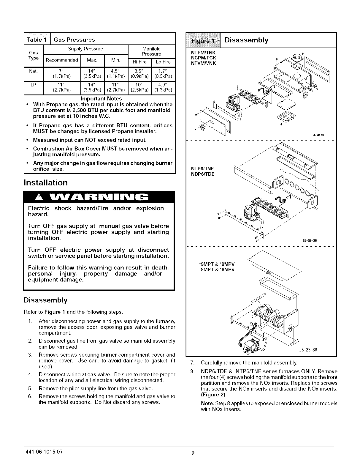
Table 1 Gas Pressures
Gas Pressure
Type Recommended Max. Min. Hi Fire Lo Fire
Nat. 7" 14" 4.5" 3.5" 1.7"
LP 11" 14" 11" 10" 4.9"
• With Propane gas, the rated input is obtained when the
BTU content is 2,500 BTU per cubic foot and manifold
pressure set at 10 inches W.C.
• If Propane gas has a different BTU content, orifices
MUST be changed by licensed Propane installer.
• Measured input can NOT exceed rated input.
• Combustion Air Box Cover MUST be removed when ad-
justing manifold pressure.
• Any major change in gas flow requires changing burner
orifice size.
Supply Pressure Manifold
(1.7kPa) (3.5kPa) (1.1kPa) (0.9kPa) (0.5kPa)
(2.7kPa) (3.5kPa) (2.7kPa) (2.5kPa) (1.3kPa)
Important Notes
Installation
Electric shock hazard/Fire and/or explosion
hazard.
Disassembly
NTPM/TNK
NCPM/TCK
NTVM/VNK
NTP6/TNE
NDP6/TDE
Turn OFF gas supply at manual gas valve before
turning OFF electric power supply and starting
installation.
Turn OFF electric power supply at disconnect
switch or service panel before starting installation.
Failure to follow this warning can result in death,
personal injury, property damage and/or
equipment damage.
Disassembly
Refer to Figure 1 and the following steps.
1. After disconnecting power and gas supply to the furnace,
remove the access door, exposing gas valve and burner
compartment.
2. Disconnect gas line from gas valve so manifold assembly
can be removed.
3. Remove screws securing burner compartment cover and
remove cover. Use care to avoid damage to gasket. (if
used)
4. Disconnect wiring at gas valve. Be sure to note the proper
location of any and all electrical wiring disconnected.
5. Remove the pilot supply line from the gas valve.
6. Remove the screws holding the manifold and gas valve to
the manifold supports. Do Not discard any screws.
_" 25-22-36
*9MPT & *9MPV
*8MPT & *8MPV
25-23-86
7.
Carefully remove the manifold assembly.
8.
NDP6/TDE & NTP6/TNE series furnaces ONLY. Remove
the four (4) screws holding the manifold supports to the front
partition and remove the NOx inserts. Replace the screws
that secure the NOx inserts and discard the NOx inserts.
(Figure 2)
Note: Step 8 applies to exposed or enclosed burner models
with NOx inserts.
441 06 1015 07 2
Page 3
High Altitude Installation
CarbonMonoxidehazard.
NOxinsertsfor usewith NaturalGasunits
ONLY.If LPGasisrequired,NOxinsertsmust
beremoved.
Failureto followthis warningcan result in
property damage,personal injury and/or
death.
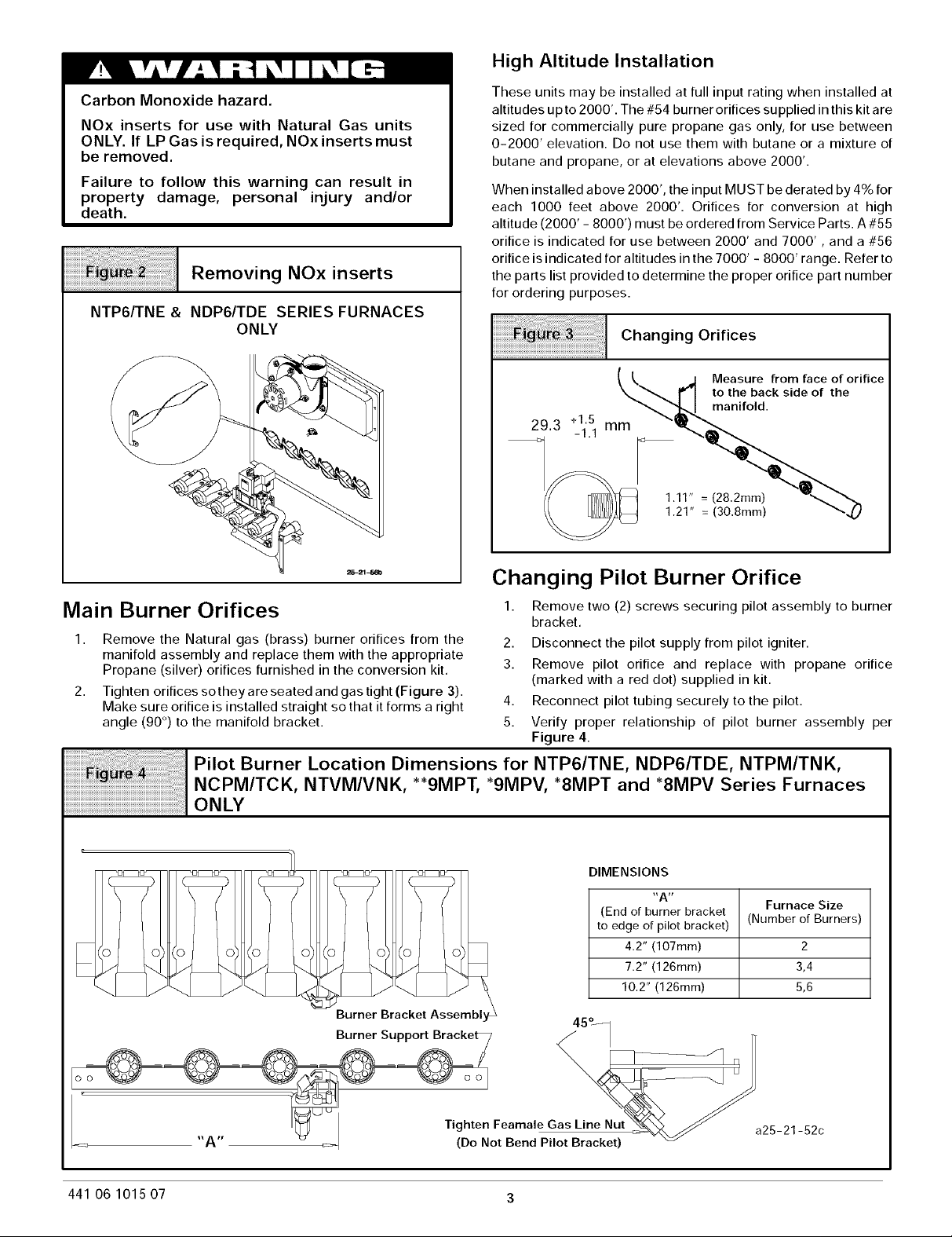
Removing NOx inserts
NTP6/TNE & NDP6/TDE SERIES FURNACES
ONLY
These units may be installed at full input rating when installed at
altitudes up to 2000'. The #54 burner orifices supplied in this kit are
sized for commercially pure propane gas only, for use between
0-2000' elevation. Do not use them with butane or a mixture of
butane and propane, or at elevations above 2000'.
When installed above 2000', the input MUST be derated by 4% for
each 1000 feet above 2000'. Orifices for conversion at high
altitude (2000' - 8000') must be ordered from Service Parts. A #55
orifice is indicated for use between 2000' and 7000', and a #56
orifice is indicated for altitudes in the 7000' - 8000' range. Refer to
the parts list provided to determine the proper orifice part number
for ordering purposes.
iiiiiiiiiiiiiiiiiiiiiiiiiii!iiiii_ii_!il! !!i!ii!ii!i!_iliiiiiiiiiiiiiiiiiiiiiiiiiiiiiiiiiiiiiiiiii!i!i!i!iiChanging Orifices
(I J Measure from face of orifice
___ _ to the back side of the
_£-,,d manifold.
293+_11.!1mm
Changing Pilot Burner Orifice
Main Burner Orifices
Remove the Natural gas (brass) burner orifices from the
1. 2. Disconnect the pilot supply from pilot igniter.
manifold assembly and replace them with the appropriate
Propane (silver) orifices furnished in the conversion kit.
Tighten orifices so they are seated and gas tight (Figure 3).
2. 4. Reconnect pilot tubing securely to the pilot.
Make sure orifice is installed straight so that it forms a right
angle (90 °) to the manifold bracket.
_i!_ l i l Pil°t Burner L°cati°n Dimensi°ns f°r Nzp61zNE' NDp61zDE' NzpMIzNK'
NCPM/TCK, NTVM/VNK, "*9MPT, *9MPV, "8MPT and *8MPV Series Furnaces
ONLY
\ /
_ _ _ 4.2"(107mm)
Burner Bracket Assembly _
Burner Support Bracke _ |
1. Remove two (2) screws securing pilot assembly to burner
bracket.
3. Remove pilot orifice and replace with propane orifice
(marked with a red dot) supplied in kit.
5. Verify proper relationship of pilot burner assembly per
Figure 4.
DIMENSIONS
,,Art
(End of burner bracket
to edge of pilot bracket)
7.2" (126mm)
10.2" (126mm)
45°_1
Furnace Size
(Number of Burners)
2
3,4
5,6
Feamale Gas Lin_e_Nut
A _ (Do.... N"^ " _ ot Bend Pilot Bracket)
441 06 1015 07 3
a25-21-52c
Page 4

Changing Pilot Orifice
Orifice with
Red Dot
25-22-17
Gas Valve Conversion
Conversion of Honeywell SV9540 & SV9541 Gas Valves using
Natural Gas Conversion Kit #396021.
1. Remove the two screws securing the Hi/Lo regulator cover
to the valve. (See Figure 6 & Figure 7)
Typical Honeywell Gas Valve
Outlet Pressure Tap Inlet Pressure Tap .Connect
on manifold.Connect manometer & check inlet
manometer & check pr, ure. (11" wc
outlet pressure recommended)
per Table 1.
Regulatol
Cover
Screws
INLET
High Fire/Low Fire
Adjusting screws
2. Remove the existing regulator spring plunger (white color)
from the regulator housing.
3. Insert the replacement spring plunger (black color)
contained in this kit into regulator housing with the spring
end down.
Typical Honeywell
Regulator Assembly
LP Natural
Gas Gas
BLACK WHITE
25-22-56
4. Replace the Hi/Lo regulator cover and secure with the two
screws.
5. Attach the Caution Label contained in the kit to the Gas
Valve where it can be readily seen.
LP Low Pressure Switch (Required for 90+
and recommended for 80+)
1. Install the inlet fitting adapter #1147904 to the inlet of the gas
valve using the O-ring and the four screws provided with the
kit. Tighten securely.
2. Using pipe joint compound that is resistant to LP gas,
tighten the fitting assembly into the inlet side of the gas
valve. (Figure 8). Position fitting assembly as shown.
3. Screw the LP pressure switch into the bushing. Use pipe
dope on connection. Tighten securely.
Note: Do not block inlet port of pressure switch with pipe dope.
Switch will not operate if inlet port is blocked.
4. Remove one blue wire from the low fire pressure switch.
Connect this wire to the male insulated blue wire in the wire
harness provided.(See Figure 8).
5. Connect the other blue wire in the harness to the open
termination on the Low Fire pressure switch.
6. Connect the other end of the wire harness to the two
terminals on the LP switch.
Note: LP switch is factory set to open if LP gas supply pressure
falls below 6" w.c.
441 06 1015 07 4
Page 5

Typical Gas Piping and Adding LP Low Pressure Switch (Required for 90+ and
recommended for 80+)
Low Fire
Switch
Switch
goes here
High Fire
Pressure
Switch
Typical left
side gas
pipe entry.
Shutoff valve
Fire
Lr%Wssure_
Switch _
Wires from kP Low \
Pressure Switch
BL
BL J \_'
Disconnect blue wire from wire harness going
Disconnect Splice
BL
\
BL--
to low fire pressure switch and connect to wire
harness splice on the blue wire going to the LP
low pressure switch, Refer to step 4 - 6.
25-22-53
25-24-27a-1
441 06 1015 07 5
Page 6

Reassembly
Reassemble all parts in reverse order as removed except leave
the burner compartment cover off (90+ONLY) until after the
manifold pressure has been adjusted. Attach LP Conversion Label
to the front exterior of the furnace,
D Manifold Assembly - Be sure to engage the main burner
orifices in the proper openings in the burners.
D Testing for leaks - After reassembly, turn the gas on and
check all joints for gas leaks using a soapy solution. All
leaks must be repaired immediately.
Start-up and Check-out
1. Remove the plug from the Inlet Pressure Tap on gas valve
and install a manometer. (See Figure 5)
2. Openmanualgaslinevalvetounit. Checkforgasleaksand
correct as necessary. Check supply pressure, 11" WC
recommended, (11" WC minimum, 14" maximum). If not
within these limitations DO NOT OPERATE
FURNACE, contact gas supplier.
3. Close manual gas line valve to unit, remove manometer and
replace inlet pressure tap plug.
Manifold Gas Pressure Adjustments (Hi &
Lo Fire)
NOTE: Gas supply pressure MUST be within minimum and
maximum values listed on rating plate. Pressures are usually set
by gas suppliers.
Make adjustment to manifold pressure with burners operating and
combustion air box cover removed.
1. Remove combustion air box cover. (90+ ONLY)
2. Connect U-Tube manometer to the tapped opening on the
outlet side of gas valve on the manifold pipe. Use a
manometer with a 0 to 12" minimum water column range.
3. Turn gas ON. Operate the furnace on high fire by using a
jumper wire on the R to Wl & W2 thermostat connections on
the fan board.
4. Remove the adjustment screw covers on the gas valve.
Turn counterclockwise to decrease the manifold pressure
and clockwise to increase.
5. Set the manifold pressure to value shown in Table 1.
6. Operate the furnace on low fire by using a jumper wire on
the R to Wl thermostat connections on the fan board.
Note: The fourth (4th) DIP switch should be in the on
position to set the low fire manifold pressure. (See wiring
diagram)
7. Repeat steps 4 and 5 for low fire operation.
8. When the manifold pressures are properly set, replace the
adjustment screw covers on the gas valve. Remove
manometer and replace plug.
9. Remove the jumper wires from the thermostat connections
on the fan board.
10. Return fourth (4th) DIP switch to correct setting.
11. Start the main burners and check pressure tap plug for gas
leaks.
12. With gas valve on, observe furnace through two or more
complete cycles to be sure all controls are operating.
13. With furnace operating, observe pilot connections for gas
leaks. Turn gas off and tighten connections if required.
14. Check and adjust pilot flame if necessary. Flame should
envelope 3/8' to 1/2' of end of igniter sensor. To adjust;
remove pilot adjustment cap on gas valve and adjust, then
replace cap. (See Figure 10)
Main Burner
,_ Burner Face
14. Turn gas valve to OFF. Remove the pressure gauge and
replace the pressure tap plug and pressure regulator cap
screw.
15. Replace burner compartment cover.
Burner Orifice Ring
10-11-92
Checking Input Rate
Checking Burner Input Using A Meter. To check the BTU input
rate, the test hand on the meter should be timed for at least one
revolution and the input determined from this timing. Refer to
Section 8, Table XIII of the National Fuel Gas Code for converting
test hand readings to cubic feet per hour.
Example
Propane Gas Time Per
BTU Content Cubic Foot in
2,500 120
Seconds
Cubic Feet BTU Per
Per Hour Hour
30 75,000
Example:
2500 BTU/ft 3 x 30 ft3/hr = 75,000 BTU/hour
Checking Burner Input Not Using a Meter. The fixed orifice size
for each burner may be used to determine the burner input in
accordance with Table F-2 of the National Fuel Gas code for
liquefied petroleum gas. Excerpt of Table F-2 is listed below.
Table F - Excerpt
Orifice # # 53 # 54 # 55
BTUH/hr at
Sea Level 28,769 24,630 21,939
For Altitudes above 5,000 feet, refer to Section, High Altitude
Installation.
Main Burner Flame Check
Check for the following:
D Stable and blue flames
D Flames extending directly from burner into heat
exchanger.
D Flames DO NOT touch sides of heat exchanger.
NOTE: Dust may cause orange tips or wisps of yellow, but flames
MUST NOT have solid, yellow tips.
441 06 1015 07 6
Page 7

Pilot Burner Flame Check
Pilot flame should envelope end of the igniter sensor 3/8" to 1/2".
Pilot Burner
High Alitude Derate Label
The derate label supplied with the orifice kit must be completed
and affixed to the furnace near the rating plate. Fill in the manifold
pressure, orifice size and revised input rate. The revised input rate
is determined in the following manner:
Proper Flame
i
Adjustment
Altitude Vs Rating Multiplier Chart
Sensor Tip
Hot Surface
Igniter
10-11-65
Sea Level - 8000' (Natural Gas)
Heat Value
Btu/Cu.Ft.
2,500
0-1999 2000-2999 3000-3999 4000-4999
1 .92 .88 .84
Elevation Above Sea Level
Verify System Operation
Upon completion of all conversion procedures, perform the
following steps to verify the system operation.
1. Turn the thermostat to its lowest temperature setting or to
OFF if equipped with a System Select Switch.
2. Turn the gas valve control knob to ON.
Refer to the parts list provided to determine the proper orifice part
numbers for ordering purposes.
High Altitude Input Rate = Nameplate Input x (Multiplier)
Example:
For a furnace with a input of 100,000 BTU/hr installed at an altitude
of 5280', the revised high altitude input is:
High Altitude Input Rate = 100,000 x 0.80 = 80,000 BTU/hr.
5000-5999
.80
3. Reinstall all access panels.
4. Turn ON all electrical power to the unit.
5. Set the thermostat to the desired temperature and the
System Select Switch to HEAT.
6. Upon call for H EAT from the thermostat, the Ignitor will ignite
the pilot flame. Upon ignition of pilot flame, the main valve
will open, providing gas for ignition of the main burners.
6000-6999
.76
7000-8000
.72
441 06 1015 07 7
 Loading...