

ICP NTV6/NNE, NTP6/TNE, NDP6/TDE Installation Instructions Manual
NTV6NNE
80+ 2-Stage & NTP6/TNE
VariableSpeedNDP6/TDE
SAFETY REQUIREMENTS
Recognize safety information. This is the safety- alert symbolZ_. When you see this symbol on the furnace and in instructions manuals
be alert to the potential for personal injury.
Understand the signal words DANGER, WARNING, or CA UTION. These words are used with the safety-alert symbol. DANGERidenti-
lies the most serious hazards, those that will result in severe personal injury or death. WARNINGsignifiesahazardthatcouldresu]tin
personal injury or death. CAUT__Nisusedt_identifyunsafe_racticesthatc_u_dresu_tinmin_r_ers_na_injury_r_r_ductand_r__erty
damage.
Installing and servicing heating equipment can be hazardous due to gas and electrical components. Only trained and qualified personnel
should install, repair, or service heating equipment.
Untrained service personnel can perform basic maintenance functions such as cleaning and replacing air filters. All other operations must
be performed by trained service personnel. When working on heating equipment, observe precautions in the literature, on tags, and on
labels attached to or shipped with the unit and other safety precautions that may apply.
Follow all safety codes. In the United States, follow all safety codes including the current edition National Fuel Gas Code (NFGC) NFPA
No. 541ANSIZ223.1. In Canada, refer to the current edition of the National Standard Canada CANICGA-B149.1 - and .2-M91 Natural
Gasand PropanelnstallationCodes(NSCNGPIC). Wear safety glasses and work gloves. Havefireextinguisheravailableduringstart-
up and adjustment procedures and service calls.
These instructions cover minimum requirements and conform to existing national standards and safety codes. In some instances, these
instructions exceed certain local codes and ordinances, especially those that may not have kept up with changing residential construction
practices. We require these instructions as a minimum for a safe installation.
f
Manufactured by:
International Comfort Products Corporation (USA)
Lewisburg, TN USA 37097
Table of Contents
I. SafeInstallation Requirements................ 2
2.Installation ............................... 4
3.Combustion & VentilationAir ................. 7
4.Vent and CombustionAir Piping .............. 9
5.HorizontalVenting ......................... 10
6.GasSupplyand Piping ...................... 10
7. Electrical Wiring.......................... 14
8. DuctworkandFilter(Upflow) ................ 16
9. DuctworkandFilter(Downflow) .............. 17
10. ChecksandAdjustments .................. 19
11.FurnaceMaintenance...................... 21
12.Sequence of Operation& Diagnostic ......... 21
13.TenchSupport andParts ................... 26
Printedin U.S.A. LP1 10/1/2002 441 01 2016 02
1. Safe Installation Requirements
Installation or repairs made by unqualified persons
can result in hazards to you and others. Installation
MUST conform with local codes or, in the absence of
local codes, with codes of all governmental authorities
having jurisdiction.
The information contained in this manual is intended
for use by a qualified service technician who is
experienced in such work, who is familiar with all
precautions and safety procedures required in such
work, and is equipped with the proper tools and test
instruments.
Failure to carefully read and follow all instructions in
this manual can result in furnace malfunction, death,
personal injury and/or property damage.
NOTE: This furnace is design certified by the American Gas
Association and the Canadian Gas Association for installation in
the United States and Canada. Refer to the appropriate codes,
along with this manual, for proper installation.
• This furnace is NOT approved for installation in mobile
homes, trailers or recreation vehicles.
• Do NOT use this furnace as a construction heater or to heat
a building that is under construction.
• Use only the Type of gas approved for this furnace (see Rat-
ing Plate on unit). Overfiring will result in failure of heat ex-
changer and cause dangerous operation. (Furnace can be
converted to L.E gas with approved kit.)
• Do NOT use open flame to test for gas leak.
• Ensure adequate combustion and ventilation air is provided
to the furnace.
• Seal supply and return air ducts.
• The vent system MUST be checked to determine that it is
the correct type and size.
• Install correct filter type and size.
• Unit MUST be installed so electrical components are pro-
tected from direct contact with water.
Safety Rules
Your unit is built to provide many years of safe and dependable
service providing it is properly installed and maintained. However,
abuse and/or improper use can shorten the life of the unit and
create hazards for you, the owner.
A. The U.S. Consumer Product Safety Commission recom-
mends that users of gas-burning appliances install carbon
monoxide detectors. There can be various sources of car-
bon monoxide in a building or dwelling. The sources could
be gas-fired clothes dryers, gas cooking stoves, water
heaters, furnaces, gas-fired fireplaces, wood fireplaces,
and several other items. Carbon monoxide can cause seri-
ous bodily injury and/or death. Therefore, to help alert
people of potentially dangerous carbon monoxide levels,
you should have carbon monoxide detectors listed by a na-
tionally recognized agency (e.g. Underwriters Laboratories
or International Approval Services) installed and main-
tained in the building or dwelling (see Note below).
B, There can be numerous sources of fire or smoke in a build-
ing or dwelling. Fire or smoke can ca use serious bodily inju-
ry, death, and/or property damage. Therefore, in order to
alert people of potentially dangerous fire or smoke, you
should have fire extinguisher and smoke detectors listed by
Underwriters Laboratories installed and maintained in the
building or dwelling (see Note below).
Note: The manufacturer of your furnace does not test any
detectors and makes no representations regarding any
brand or type of detector.
C. To ensure safe and efficient operation of your unit, you
should do the the following:
1. Thoroughly read this manual and labels on the unit.
This will help you understand how your unit operates and
the hazards involved with gas and electricity.
2,
Do not use this unit if any part has been under water.
Immediately call a qualified service technician to inspect
the unit and to replace any part of the control system and
any gas control which has been under water.
3. Never obstruct the vent grilles, or any ducts that pro-
vide air to the unit. Air must be provided for proper com-
bustion and ventilation of flue gases.
Carbon monoxide or "CO" is a colorless and odorless gas
produced when fuel is not burned completely or when the
flame does not receive sufficient oxygen.
Freezing Temperatures and Your Structure
Freeze warning.
Turn off water system.
If your unit remains shut off during cold weather the
water pipes could freeze and burst, resulting in serious
water damage.
Your unit is equipped with safety devices that may keep it from op-
erating if sensors detect abnormal conditions such as clogged ex-
haust flues.
If the structure will be unattended during cold weather you should
take these precautions.
1. Turn off main supply water into the structure and drain the
water lines if possible. Open faucets in appropriate areas.
2,
Have someone check the structure frequently during cold
weather to make sure it is warm enough to prevent pipes
from freezing. Suggest they call a qualified service agency,
if required.
441 01 2016 02
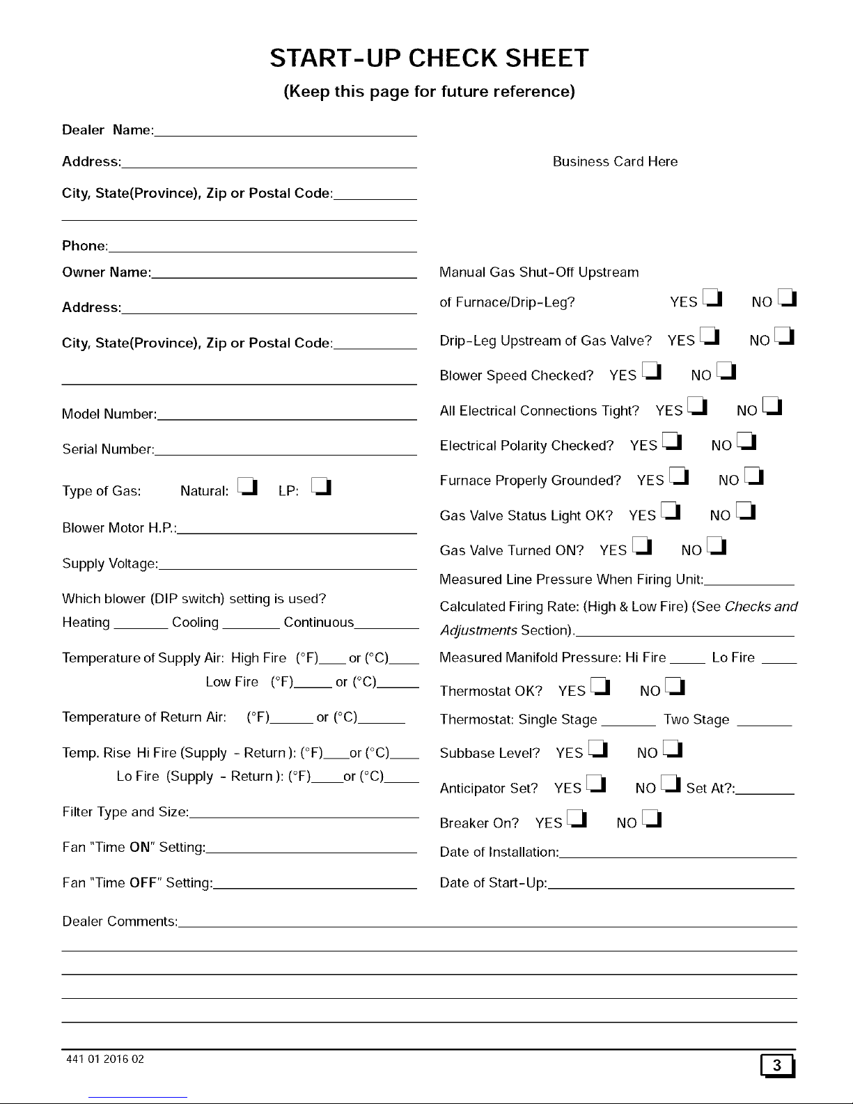
START-UP CHECK SHEET
(Keep this page for future reference)
Dealer Name:
Address:
City, State(Province), Zip or Postal Code:
Business Card Here
Phone:
Owner Name:
Address:
City, State(Province), Zip or Postal Code:
Model Number:
Serial Number:
Type of Gas: Natural: _ LP:
Blower Motor H.P.:
Supply Voltage:
Which blower (DIP switch) setting is used?
Heating Cooling Continuous
Temperature of Supply Air: High Fire (°F)__ or (°C).__
Low Fire (°F)__or (°C)__
Temperature of Return Air: (°F)__ or (°C)__
Temp. Rise Hi Fire (Supply - Return ): (°F)or (°C',__
Lo Fire (Supply - Return ): (°F) or (°C)__
Filter Type and Size:
Fan "Time ON" Setting:
Fan "Time OFF" Setting:
Dealer Comments:
Manual Gas Shut-Off Upstream
of Furnace/Drip-Leg? YES
Drip-Leg Upstream of Gas Valve? YES
Blower Speed Checked? YES _ NO
All Electrical Connections Tight?
Electrical Polarity Checked?
Furnace Properly Grounded?
Gas Valve Status Light OK?
NOE_
NoE I
YES _I NO _I
YES _I NO _I
YES _I NO _I
YES _I NO _I
Gas Valve Turned ON? YES _ NO
Measured Line Pressure When Firing Unit:
Calculated Firing Rate: (High & Low Fire) (See Checks and
Adjustments Section).
Measured Manifold Pressure: Hi Fire Lo Fire
Thermostat OK? YES _ NO
Thermostat: Single Stage Two Stage
Subbase Level? YES _ NO
Anticipator Set? YES _ NO _ Set At?:
Breaker On? YES _ NO
Date of Installation:
Date of Start-Up:
441 01 2016 02 [_
2. Installation
Poison carbon monoxide gas hazard.
If this furnace is replacing a previously common-vented
furnace, it may be necessary to resize the existing vent
line and chimney to prevent oversizing problems for the
other remaining appliances(s). See applicable codes
and Venting and Combustion Air Check in Gas Vent
Installation section.
Failure to properly vent this furnace or other appliances
can result in death, personal injury and/or property
damage.
Location and Clearances
If furnace is a replacement, it is usually best to install the furnace
where the old one was. Choose the location or evaluate the exist-
ing location based upon the minimum clearance and furnace di-
mensions (Figure 1, Figure 2 or Figure 3).
CAUTION
Do NOT operate furnace in a corrosive atmosphere contain-
ing chlorine, fluorine or any other damaging chemicals. Refer
to Combustion & Ventilation Air section, Contaminated Com-
bustion Air.
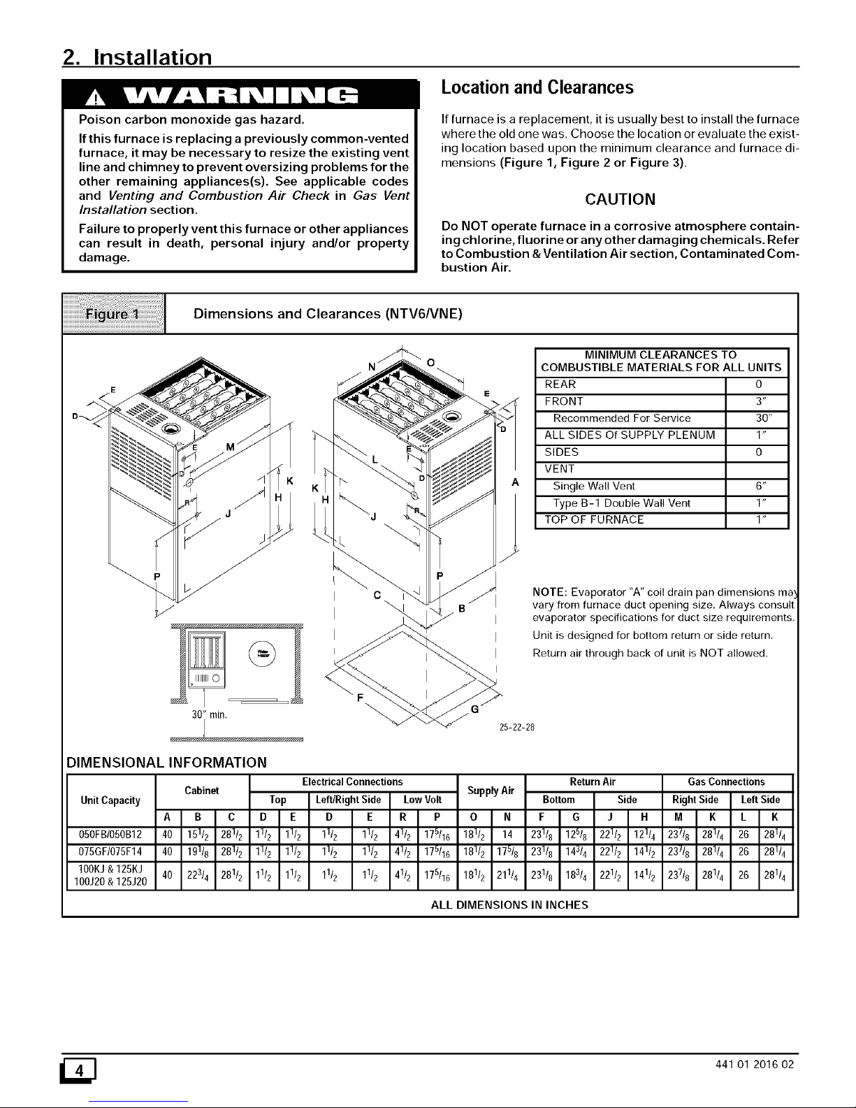
Dimensions and Clearances (NTV6NNE)
@
30" rain.
25-22-28
MINIMUM CLEARANCES TO
COMBUSTIBLE MATERIALS FOR ALL UNITS
REAR 0
FRONT 3"
Recommended For Service 30"
ALL SIDES Of SUPPLY PLENUM 1"
SIDES 0
VENT
Single Wall Vent 6"
Type B-1 Double Wall Vent 1"
TOP OF FURNACE 1"
NOTE: Evaporator "A" coil drain pan dimensions ma
vary from furnace duct opening size. Always consul
evaporator specifications for duct size requirements
Unit is designed for bottom return or side return.
Return air through back of unit is NOT allowed.
DIMENSIONAL INFORMATION
Unit Capacity
Electrical Connections
Cabinet
B C
15112 28112
19118 28112
223/4 28112
A
050FBI050BI2 40
075GF/075F14 40
100KJ& 125KJ
40
100J20& 125J20
ALL DIMENSIONS IN INCHES
Top Left/Right Side LowVolt
D E D E R P
1112 11/2 11/2 1112 41/2 175116
11/2 11/2 11/2 11/2 41/2 175116
1112 11/2 11/2 1112 41/2 175116
Supply Air
O N
18112 14
181/2 175/8
18112 21114
ReturnAir
Bottom Side
F G J H
23118 12518 22112 12114
231/8 143/4 22112 14112
23118 18314 22112 14112
GasConnections
RightSide LeftSide
M K L K
237/8 28114 26 281I
23718 28114 26 281/
23718 281/4 26 281I
_] 441 O1 201602
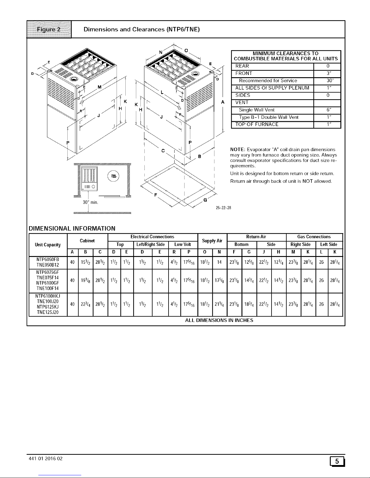
Dimensions and Clearances (NTP6/TNE)
@
Illllllll0
30" rain.
25-22-28
MINIMUM CLEARANCES TO
COMBUSTIBLE MATERIALS FOR ALL UNITS
REAR 0
FRONT 3"
Recommended for Service 30"
ALL SIDES Of SUPPLY PLENUM 1"
SIDES 0
VENT
Single Wall Vent 6"
Type B-1 Double Wall Vent 1"
TOP OF FURNACE 1"
NOTE: Evaporator "A" coil drain pan dimensions
may vary from furnace duct opening size, Always
consult evaporator specifications for duct size re-
quirements.
Unit is designed for bottom return or side return.
Return air through back of unit is NOT allowed.
DIMENSIONAL INFORMATION
Unit Capacity
Cabinet
A B C
40 15112 28112
ElectricalConnections
Top Left/Right Side Low Volt
D E D E R P
11/2 11/2 11/2 11/2 41/2 178116
Supply Air
O N
18112 14
ReturnAir
Bottom Side
F G J H
23118 12818 22112 12114
GasConnections
RightSide Left Side
M K L K
23718 28114 26 281/
NTP6050FB
TNE050BI2
NTP6075GF
TNEO75FI4
40 19118 28112 11/2 11/2 11/2 11/2 41/2 178116 18112 17518 23118 14314 22112 14112 23718 28114 26 281/
NTP6100GF
TNE100F14
NTP6100HKJ
TNE100J20
40 223/4 28112 11/2 11/2 11/2 11/2 41/2 178116 181/2 211/4 231/8 183/4 22112 14112 237/8 281/4 26 281/
NTP6125KJ
TNE125J20
ALL DIMENSIONS IN INCHES
441 O1 2016 02 [_
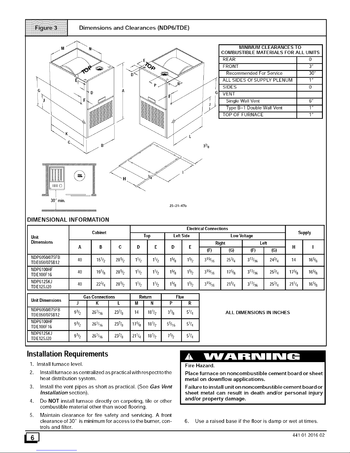
Dimensions and Clearances (NDP6/TDE)
....
c_ B_" 37/8
30" rain.
MINIMUM CLEARANCES TO
COMBUSTIBLE MATERIALS FOR ALL UNITS
REAR 0
FRONT 3"
Recommended For Service 30"
ALL SIDES Of SUPPLY PLENUM 1"
SIDES 0
VENT
Single Wall Vent 6"
Type B-1 Double Wall Vent 1"
TOP OF FURNACE 1"
25-21-47b
DIMENSIONAL INFORMATION
Unit
Dimensions
Cabinet
A
40
40
40
Electrical Connections
B C
151/2 28112
19116 281/2
22314 28112
Top
D E
11/2 11/2
11/2 1112
1112 11/2
LeftSide
D E
Right
(F)
Low Voltage
(G) (F)
NDP6050/O75FB 15/8 11/2 315116 253/4 313116
TDEOSO/O75B12
NDP61OOHF 1518 11/2 315/16 175/6 313116
TDE1OOF16
NDP6125KJ 15/8 1112 315116 211/4 313/16
TDE125J20
Left
(G)
24314
25314
25314
GasConnections Return Flue
Unit Dimensions
J K L M N P R
NDP6050/O75FB 91/2 261116 23718 14 18112 37/8 51/4
TDEO5O/O75B12
NDP610OHF 9112 261116 237/8 175i6 181i2 55116 51/4
TDE1OOF16
NDP6125KJ 91/2 261116 237/8 211i4 181/2 71/2 5114
TDE125J20
ALL DIMENSIONS IN INCHES
Supply
H I
14 165/6
17518 165/6
211i4 16516
Installation Requirements
1. Install furnace level.
2. Install furnace as centralized as practical with respect to the
heat distribution system.
3. Install the vent pipes as short as practical. (See Gas Vent
Installation section).
4. Do NOT install furnace directly on carpeting, tile or other
combustible material other than wood flooring.
5. Maintain clearance for fire safety and servicing. A front
clearance of 30" is minimum for access to the burner, con-
trols and filter.
Fire Hazard.
Place furnace on noncombustible cement board or sheet
metal on downflow applications.
Failure to install unit on noncombustible cement board or
sheet metal can result in death and/or personal injury
and/or property damage.
6. Use a raised base if the floor is damp or wet at times.
441 O1 201602
7. Residentialgarageinstallationsrequire:
• Burners and ignition sources installed at least 18" (457mm)
above the floor.
• Furnace must be located or physically protected from pos-
sible damage by a vehicle.
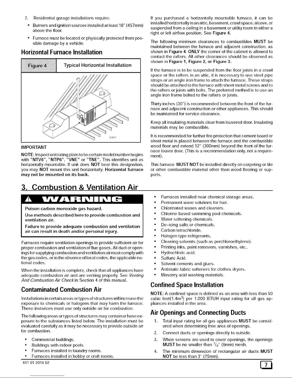
Horizontal Furnace Installation
Typical Horizontal Installation
IMPORTANT
NOTE: Inspect unit rating plate to be certain model number begins
with "NTV6", "NTP6", "VNE" or "TNE". This identifies unit as
horizontally mountable. If unit does NOT bear this designation,
you may NOT mount this unit horizontally. Horizontal furnace
may not be mounted on its back.
If you purchased a horizontally mountable furnace, it can be
installed horizontally in an attic, basement, crawl space, alcove, or
suspended from a ceiling in a basement or utility room in either a
right or left airflow position. See Figure 4.
The following minimum clearances to combustibles MUST be
maintained between the furnace and adjacent construction, as
shown in Figure 4. ONLY the corner of the cabinet is allowed to
contact the rafters. All other clearances should be observed as
shown in Figure 1, Figure 2, or Figure 3.
If the furnace is to be suspended from the floor joists in a crawl
space or the rafters in an attic, it is necessary to use steel pipe
straps or an angle iron frame to attach the furnace. These straps
should be attached to the furnace with sheet metal screws and to
the rafters or joists with bolts. The preferred method is to use an
angle iron frame bolted to the rafters or joists.
Thirty inches (30") is recommended between the front of the fur-
nace and adjacent construction or other appliances. This should
be maintained for service clearance.
Keep all insulating materials clear from Iouvered door. Insulating
materials may be combustible.
It is recommended for further fire protection that cement board or
sheet metal is placed between the furnace and the combustible
wood floor and extend 12" (300mm) beyond the front of the fur-
nace louver door. (This is a recommendation only, not a require-
ment).
This furnace MUST NOT be installed directly on carpeting or tile
or other combustible material other than wood flooring or sup-
ports.
3. Combustion & Ventilation Air
Poison carbon monoxide gas hazard.
Use methods described here to provide combustion and
ventilation air.
Failure to provide adequate combustion and ventilation
air can result in death and/or personal injury.
Furnaces require ventilation openings to provide sufficient air for
proper combustion and ventilation of flue gases. All duct or open-
ings for su pplying combustion and ventilation air must comply with
the gas codes, or in the absence of local codes, the applicable na-
tional codes.
When the installation is complete, check that all appliances have
adequate combustion air and are venting properly. See Venting
And Combustion Air Check in Section 4 of this manual.
• Furnaces installed near chemical storage areas.
• Permanent wave solutions for hair.
• Chlorinated waxes and cleaners.
• Chlorine based swimming pool chemicals.
• Water softening chemicals.
• De-icing salts or chemicals.
• Carbon tetrachloride.
• Halogen type refrigerants.
• Cleaning solvents (such as perchloroethylene).
• Printing inks, paint removers, varnishes, etc..
• Hydrochloric acid.
• Sulfuric Acid.
• Solvent cements and glues.
• Antistatic fabric softeners for clothes dryers.
• Masonry acid washing materials.
Contaminated Combustion Air
Installations in certain areas or types of structures will increase the
exposure to chemicals or halogens that may harm the furnace.
These instances must use only outside air for combustion.
The following areas or types of structures may contain or have ex-
posure to the substances listed below. The installation must be
evaluated carefully as it may be necessary to provide outside air
for combustion.
• Commercial buildings.
• Buildings with indoor pools.
• Furnaces installed in laundry rooms.
• Furnaces installed in hobby or craft rooms.
44101 2016 02
Confined Space Installation
NOTE: A confined space is defined as an area with less than 50
cubic feet(1.4m 3) per 1,000 BTUH input rating for all gas ap-
pliances installed in the area.
Air Openings and Connecting Ducts
1. Total input rating for all gas appliances MUST be consid-
ered when determining free area of openings.
2. Connect ducts or openings directly to outside.
3. When screens are used to cover openings, the openings
MUST be no smaller than 1/4" (6ram) mesh.
4. The minimum dimension of rectangular air ducts MUST
NOT be less than 3" (75ram).
5. Whensizinggrilleorlouver,usethefreeareaofopening.If
freeareaisNOTstampedormarkedongrillorlouver,as-
sumea20%freeareaforwoodand60%formetal.
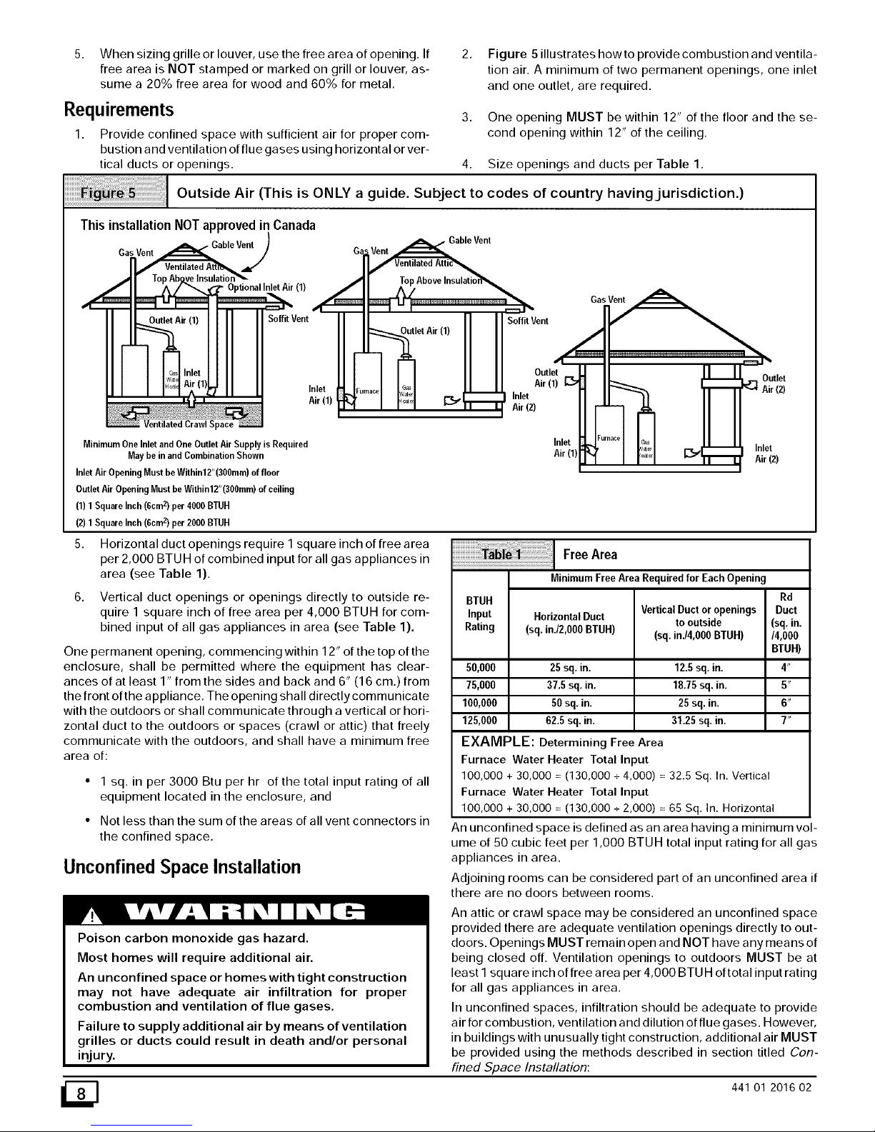
2.
Figure 5 illustrates how to provide combustion and ventila-
tion air. A minimum of two permanent openings, one inlet
and one outlet, are required.
Requirements 3.
1. Provide confined space with sufficient air for proper com-
bustion and ventilation of flue gases using horizontal or ver-
tical ducts or openings. 4. Size openings and ducts per Table 1.
Outside Air (This is ONLY a guide. Subject to codes of country having jurisdiction.)
One opening MUST be within 12" of the floor and the se-
cond opening within 12" of the ceiling.
ThisinstallationNOTapprovedin Canada
, GableVent
GasVent
(1)
.d
SoffitVent
Inlet
Air (1
MinimumOne Inlet and OneOutlet Air Supplyis Required
May be in andCombination Shown
InletAir OpeningMustbe Within12"(300ram)offloor
OutletAir OpeningMustbeWithin12"(300mm)ofceiling
(1) 1SquareInch(6cmz) per 4000BTUH
(2) 1SquareInch(6cmz) per 2000BTUH
/
letAir(1) HI
Soffit Vent
Outlet
Air (1)
Inlet
Air (2)
Inlet
Air (1)
Furnace
G_
[[_J Outlet
Air (2)
E_:_,_r._ T Inlet
Air (2)
5. Horizontal duct openings require I square inch of free area
per 2,000 BTU Hof combined input for all gas appliances in
area (see Table 1).
6. Vertical duct openings or openings directly to outside re-
quire 1 square inch of free area per 4,000 BTUH for com-
bined input of all gas appliances in area (see Table 1).
One permanent opening, commencing within 12" of the top of the
enclosure, shall be permitted where the equipment has clear-
ances of at least 1" from the sides and back and 6" (16 cm.) from
the front of the appliance. The opening shall directly communicate
with the outdoors or shall communicate through a vertical or hori-
zontal duct to the outdoors or spaces (crawl or attic) that freely
communicate with the outdoors, and shall have a minimum free
area of:
• 1 sq. in per 3000 Btu per hr of the total input rating of all
equipment located in the enclosure, and
• Not less than the sum of the areas of all vent connectors in
the confined space.
Unconfined Space Installation
FreeArea
MinimumFreeArea Requiredfor EachOpening
BTUH Rd
Input HorizontalDuct VerticalDuctoropenings Duct
to outside (sq,in.
Rating (sq.in,i2,000BTUH) (sq.in./4,000BTUH) /4,000
BTUH)
50,000 25sq. in, 12.5sq, in. 4"
75,000 37.5 sq, in, 18.75sq. in, 5"
100,000 50sq, in. 25sq. in. 6"
125,000 62,5 sq. in. 31.25sq. in, 7"
EXAMPLE: Determining Free Area
Furnace Water Heater Total Input
100,000 + 30,000 = (130,000 + 4,000) = 32.5 Sq. In. Vertical
Furnace Water Heater Total Input
100,000 + 30,000 = (130,000 + 2,000) = 65 Sq. In. Horizontal
An unconfined space is defined as an area having a minimum vol-
ume of 50 cubic feet per 1,000 BTUH total input rating for all gas
appliances in area.
Adjoining rooms can be considered part of an unconfined area if
there are no doors between rooms.
Poison carbon monoxide gas hazard.
Most homes will require additional air.
An unconfined space or homes with tight construction
may not have adequate air infiltration for proper
combustion and ventilation of flue gases.
Failure to supply additional air by means of ventilation
grilles or ducts could result in death and/or personal
injury.
An attic or crawl space may be considered an unconfined space
provided there are adequate ventilation openings directly to out-
doors. Openings MUST remain open and NOT have any means of
being closed off. Ventilation openings to outdoors MUST be at
least I square inch of free area per 4,000 BTU H oftotal input rating
for all gas appliances in area.
In unconfined spaces, infiltration should be adequate to provide
air for combustion, ventilation and dilution of flue gases. However,
in buildings with unusually tight construction, additional air MUST
be provided using the methods described in section titled Con-
fined Space Installation:
441 01 201602
Unusuallytightconstructionisdefinedas:Constructionwith
1 Wallsandceilingsexposedtotheoutsidehaveacontinu-
ous,sealedvaporbarrier.Openingsaregasketedorsealed
and
2 Doorsandopenablewindowsareweatherstrippedand
3. Otheropeningsarecaulkedorsealed.Theseincludejoints
aroundwindowanddoorframes,betweensoleplatesand
floors,betweenwall-ceilingjoints,betweenwallpanels,at
penetrationsforplumbing,electricalandgaslines,etc.
4. Gas Vent Installation
Poison carbon monoxide gas, fire and explosion
hazard.
Ventilation Air
Some provincial codes and local municipalities require ventilation
or make-up air be brought into the conditioned space as replace-
ment air. Whichever method is used, the mixed return air tempera-
ture across the heat exchanger MUST not fall below 60°F or flue
gases will condense in the heat exchanger. This will shorten the
life of the heat exchanger and possibly void your warranty.
Read and follow all instructions in this section.
Failure to properly vent this furnace can result in death,
personal injury and/or property damage.
Install the vent in compliance with codes of the country having ju-
risdiction, local codes or ordinances and these instructions.
Poison carbon monoxide gas hazard.
If this furnace is replacing a previously common-vented
furnace, it may be necessary to resize the existing
chimney liner or vent to prevent over sizing problems for
the other remaining appliances(s). See codes of country
having jurisdiction.
Failure to properly vent this furnace or other appliances
can result in death, personal injury and/or property
damage.
These fan assisted combustion furnaces have been classified as
Category [ appliances which means that they MUST operate with
a negative vent pressure.
Category I Safe Venting Requirements
NOTE: The following instructions comply with the United States
National Fuel Gas Code. Based on the highest input rate on the
furnace rating plate.
If a Category [ vent passes through an attic, any concealed
space or floor, use ONLY Type B or Type L double wall vent
pipe. If vent pipe passes through interior wall, use type B
vent pipe with ventilated thimble ONLY.
2. Do NOT vent furnace into any chimney serving an open
fireplace or solid fuel burning appliance.
3. Use the same diameter Category [ connector or pipe as
permitted by the United States National Fuel Gas Code
venting tables.
4. Keep vertical Category [vent pipe orvent connector runs as
short and direct as possible.
5. Vertical outdoor runs of type B or ANY single wall vent pipe
below the roof line are NOT permitted.
6. Slope all horizontal runs up away from furnace a minimum
of 1/4" per foot.
7. Support all horizontal vent pipe every 6' using proper
clamps and metal straps.
8. Check existing gas vent or chimney to ensure they meet
clearances and local codes.
The furnace MUST be connected to a factory built chimney
or vent complying with a recognized standard. Venting into
a masonry or concrete chimney is only permitted as
outlined in the United States National Fuel Gas Code
venting tables or Masonry Chimney section in these
instructions.
441 01 2016 02
Venting and Combustion Air Check
NOTE: If this installation removes an existing furnace from a vent-
ing system serving one or more other appliances, and to make
sure there is adequate combustion air for all appliances, MAKE
THE FOLLOWING CHECK.
1,
2.
Seal any unused openings in the venting system.
Visuallyinspect the venting system for proper size and hori-
zontal pitch to ensure there is no blockage or restriction,
leakage, corrosion or other deficiencies which could cause
an unsafe condition.
3. Insofar as is practical, close all doors and windows and all
doors between the space in which the appliance(s) remain-
ing connected to the venting system are located and other
spaces of the building.
4. Turn on clothes dryers and any appliance not connected to
the venting system. Turn on any exhaust fans, such as
range hoods and bathroom exhausts, so they will operate at
maximum speed. Do not operate a summer exhaust fan.
Close fireplace dampers.
5. Follow the lighting instructions for each appliance being in-
spected. Adjust thermostat so appliance(s) will operate
continuously.
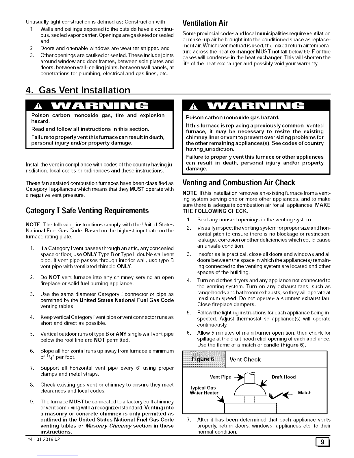
6. Allow 5 minutes of main burner operation, then check for
spillage at the draft hood relief opening of each appliance.
Use the flame of a match or candle (Figure 6).
Vent Check
Vent Pipe Draft Hood
Typical Gas
Water Heater [ 1 I _--
Match
7.
After it has been determined that each appliance vents
properly, return doors, windows, appliances etc. to their
normal condition.
8. If improper venting is observed, the cause MUST be cor-
rected.
NOTE: If flame pulls towards draft hood, this indicates sufficient
infiltration air.
Venting to Existing Masonry Chimney
NOTE: The tables and notes referred to below are found in the
most recent printing of the United States National Fuel Gas
Code venting tables.
Use the United States National Fuel Gas Code or NFGC Tables to
size the chimney or vent. Dedicated venting of one fan assisted
furnace into any masonry chimney is restricted. The chimney
must first be lined with either type B vent sized in accordance with
tables 1 or 2 or a listed single wall, metal lining system, sized in
accordance with the vent tables.
Listed, corrugated metallic chimney liner systems in masonry
chimneys shall be sized by using United States National Fuel
Gas Code tables for dedicated venting and United States Na-
tional Fuel Gas Code tables for common venting with the maxi-
mum capacity reduced by 20% (0.80 X maximum capacity) and
the minimum capacity as shown in the applicable table. Corru-
gated metal vent systems installed with bends or offsets require
additional reduction of 10% of the vent capacity for each 90 ° el-
bow.
NOTE: Two(2) 45° elbows are equivalent to one (1) 90° elbow.
Combined Venting into a Masonry Chimney
Venting into a masonry or concrete chimney is only per-
mitted as outlined in the United States National Fuel Gas
Code venting tables. Follow all safe venting requirements.
5. Horizontal Venting
Category ] Furnaces With External Power
Venters
In order to maintain a Category ] classification of fan assisted fur-
naces when vented horizontally with sidewall termination, a power
venter is REQUIRED to maintain a negative pressure in the vent-
ing system. Please consult the Fields Controls Co. or Tjernlund
Products, Inc. for power Venters certified for use with our fur-
Races.
Vent Termination
Venting Through a Non-Combustible and
Combustible Wall
CAUTION
It is the responsibility of the installer to properly termi-
nate the vent and provide adequate shielding. This is
essential in order to avoid water/ice damage to build-
ing, shrubs and walk-ways.
Consult External Power Venter manufacturer instructions.
6. Gas Supply and Piping
Poison carbon monoxide gas hazard.
Models designated for Natural Gas are to be used with
Natural Gas ONLY, unless properly converted to use
with LP gas.
Failure to follow these instructions can result in death,
personal injury and/or property damage.
GasSupplyRequirements
• Use only the Type of gas approved for this furnace. See rat-
ing plate for approved gas type.
• Gas input must not exceed the rated input shown on the rat-
ing plate. Overfiring will result in failure of heat exchanger
and cause dangerous operation.
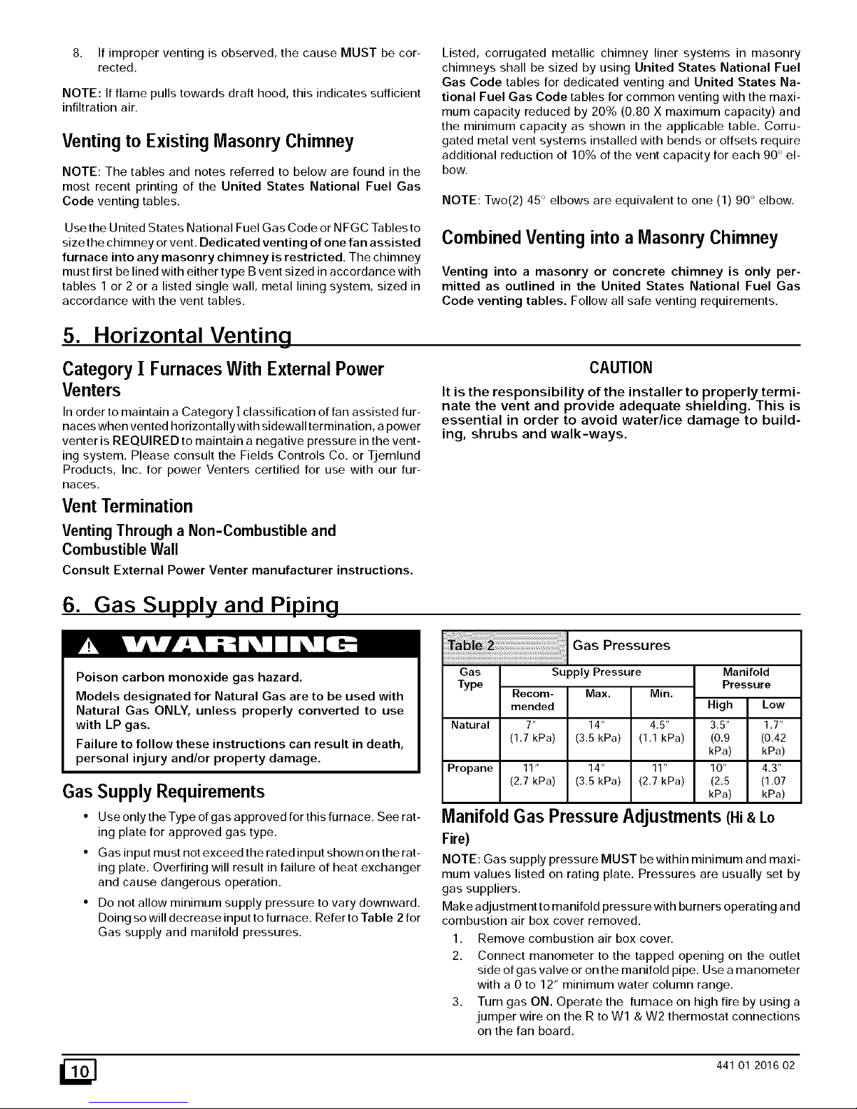
• Do not allow minimum supply pressure to vary downward.
Doing so will decrease input to furnace. Refer to Table 2 for
Gas supply and manifold pressures.
Gas Pressures
•________________________________________________________________________________________________
Gas
Supply Pressure
Type
Recom- Max. Min.
mended
Natural 7" 14" 4.5"
(1.7 kPa) (3.5 kPa) (1.1 kPa)
Propane 11" 14" 11"
(2.7 kPa) (3.5 kPa) (2.7 kPa)
Manifold
Pressure
High Low
3.5" 1.7"
(0.9 (0.42
kPa) kPa)
10" 4.3"
(2.5 (1.07
kPa) kPa)
Manifold Gas Pressure Adjustments (Hi&Lo
Fire)
NOTE: Gas supply pressure MUST be within minimum and maxi-
mum values listed on rating plate. Pressures are usually set by
gas suppliers.
Make adjustment to manifold pressure with burners operating and
combustion air box cover removed.
1. Remove combustion air box cover.
2. Connect manometer to the tapped opening on the outlet
side of gas valve or on the manifold pipe. Use a manometer
with a 0 to 12" minimum water column range.
3. Turn gas ON. Operate the furnace on high fire by using a
jumper wire on the R to Wl & W2 thermostat connections
on the fan board.
_] 441 01 2016 02
4. Removetheadjustmentcoveronthegasvalve.Turnad-
justingscrewcounterclockwisetodecreasethemanifold
pressureandclockwisetoincrease.SeeFigure29.
5. Setthe manifold pressure to value shown in Table 2,
Table 3 or Table 4.
6. Operate the furnace on low fire by using a jumper wire on
the R to Wl thermostat connections on the fan board.
Note: The fourth (4th) DIP switch should be in the on posi-
tion to set the low fire manifold pressure. (See wiring dia-
gram)
7. Repeat steps 4 and 5 for low fire operation.
8. When the manifold pressures are properly set, replace the
adjustment screw covers on the gas valve.
9. Removethejumper wires from the thermostat connections
on the fan board. Remove manometer and replace plug in
manifold.
10. Replace combustion air box cover.
11. Return fourth (4th) DIP switch to previous setting.
Natural Gas Input Rating Check
NOTE: The gas meter can be used to measure input to furnace.
Rating is based on a natural gas BTU content of 1,000 BTU's per
cubic meter. Check with gas supplier for actual BTU content.
1. Make sure combustion air box cover is in place and closed
before performing the following steps.
2. Turn OFF gas supply to all appliances and start furnace.
Use jumper wire on R to W1 and W2 for Hi fire.
3. Time how many seconds it takes the smallest dial on the
gas meter to make one complete revolution. Refer to Ex-
ample.
4. Repeat steps 2 and 3 with jumper wire on R to Wl for low
fire. NOTE: Fourth (4th) DIP switch must be in on position.
(See furnace wiring diagram). Return fourth (4th) DIP
switch to previous setting after check.
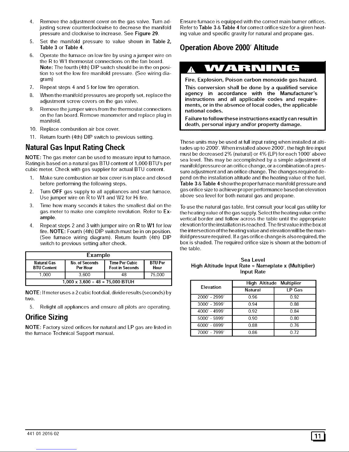
Example
NaturaIGas No.of Seconds TimePer Cubic | BTU Per
BTUContent PerHour Foot inSeconds ] Hour
1,000 3,600 48 75,000
1,000 x 3,600 + 48 = 75,000 BTUH
NOTE: If meter uses a 2 cubic foot dial, divide results (seconds) by
two.
5. Relight all appliances and ensure all pilots are operating.
Orifice Sizing
NOTE: Factory sized orifices for natural and LP gas are listed in
the furnace Technical Support manual.
Ensure furnace is equipped with the correct main burner orifices.
Refer to Table 3 & Table 4 for correct orifice size for a given heat-
ing value and specific gravity for natural and propane gas.
Operation Above 2000' Altitude
Fire, Explosion, Poison carbon monoxide gas hazard.
This conversion shall be done by a qualified service
agency in accordance with the Manufacturer's
instructions and all applicable codes and require-
ments, or in the absence of local codes, the applicable
national codes.
Failure to follow these instructions exactly can result in
death, personal injury and/or property damage.
These units may be used at full input rating when installed at alti-
tudes up to 2000'. When installed above 2000', the high fire input
must be decreased 2% (natural) or 4% (LP) for each 1000' above
sea level. This may be accomplished by a simple adjustment of
manifold pressure or an orifice change, or a combination of a pres-
sure adjustment and an orifice change. The changes required de-
pend on the installation altitude and the heating value of the fuel.
Table 3 & Table 4 showthe proper furnace manifold pressure and
gas orifice size to achieve proper performance based on elevation
above sea level for both natural gas and propane.
To use the natural gas table, first consult your local gas utility for
the heating value of the gas supply. Select the heating value on the
vertical border and follow across the table until the appropriate
elevation for the installation is reached. The first value in the box at
the intersection of the heating value and elevation will be the man-
ifold pressure required. If a gas orifice change is also required, the
box is shaded. The required orifice size is shown at the bottom of
the table.
Sea Level
High Altitude Input Rate = Nameplate x (Multiplier)
Input Rate
Elevation
2000'-2999'
3000'-3999'
4000'-4999'
5000'-5999'
6000'-6999'
7000'-7999'
High Altitude Multiplier
Natural LP Gas
0.96 0.92
0.94 0.88
0.92 0.84
0.90 0.80
0.88 0.76
0.86 0.72
441 01 2016 02 [_
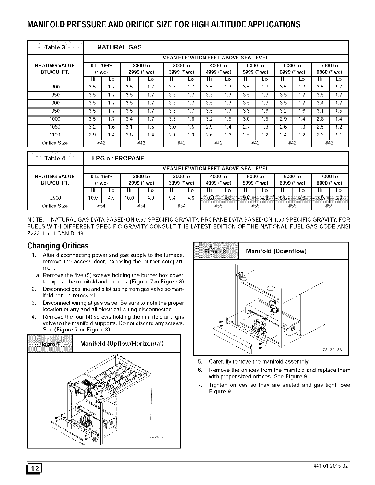
MANIFOLDPRESSUREAND ORIFICESIZEFORHIGH ALTITUDEAPPLICATIONS
Table3
NATURAL GAS
MEAN ELEVATION FEET ABOVE SEA LEVEL
HEATING VALUE 3000 to 4000 to 5000 to
BTU/CU. FT, 3999 (" wc) 4999 (" wc) 5999 (" wc)
0 to 1999 2000 to
("wc) 2999("wc)
Hi Lo Hi Lo Hi Lo Hi Lo Hi Lo
800 3.5 1.7 3.5 1.7 3.5 1.7 3.5 1.7 3.5 1.7
850 3.5 1.7 3.5 1.7 3.5 1.7 3.5 1.7 3.5 1.7
900 3.5 1.7 3.5 1.7 3.5 1.7 3.5 1.7 3.5 1.7
950 3.5 1.7 3.5 1.7 3.5 1.7 3.5 1.7 3.3 1.6
1000 3.5 1.7 3.4 1.7 3.3 1.6 3.2 1.5 3.0 1.5
1050 3.2 1.6 3.1 1.5 3.0 1.5 2.9 1.4 2.7 1.3
1100 2.9 1.4 2.8 1.4 2.7 1.3 2.6 1.3 2.5 1.2
Orifice Size #42 #42 #42 #42 #42
Table 4
HEATING VALUE
BTU/CU, FT.
2500
Orifice Size
6000 to 7000 to
6999 (" wc) 8000 (" wc)
Hi Lo Hi Lo
3.5 1.7 3.5 1.7
3.5 1.7 3.5 1.7
3.5 1.7 3.4 1.7
3.2 1.6 3.1 1.5
2.9 1.4 2.8 1.4
2.6 1.3 2.5 1.2
2.4 1.2 2.3 1.1
#42 #42
LPG or PROPANE
0 to 1999
("wc)
Hi I Lo10.0 4.9
#54
2000 to
2999 (" wc)
Hi I Lo10.0 4.9
#54
MEAN ELEVATION FEET ABOVE SEA LEVEL
3000 to 4000 to 5000 to
3999 (" wc) 4999 (" wc) 5999 (" wc)
Hi I Lo9.4 4.6
#54 #55 #55
6000 to
6999 (" wc)
7000 to
8000 ("wc)
#55 #55
NOTE: NATURAL GAS DATA BASED ON 0.60 SPECIFIC GRAVITY. PROPANE DATA BASED ON 1.53 SPECIFIC GRAVITY. FOR
FUELS WITH DIFFERENT SPECIFIC GRAVITY CONSULT THE LATEST EDITION OF THE NATIONAL FUEL GAS CODE ANSI
Z223.1 and CAN B149.
Changing Orifices
1. After disconnecting power and gas supply to the furnace,
remove the access door, exposing the burner compart-
ment.
a. Remove the five (5) screws holding the burner box cover
to expose the manifold and burners. (Figure 7 or Figure 8)
2. Disconnect gas line and pilot tubing from gas valve so man-
ifold can be removed.
3. Disconnect wiring at gas valve. Be sure to note the proper
location of any and all electrical wiring disconnected.
4. Remove the four (4) screws holding the manifold and gas
valve to the manifold supports. Do not discard any screws.
See (Figure 7 or Figure 8).
Manifold (Upflow/Horizontal)
25-22-32
Manifold (Downflow)
25-22-38
5. Carefully remove the manifold assembly.
6. Remove the orifices from the manifold and replace them
with proper sized orifices. See Figure 9.
7. Tighten orifices so they are seated and gas tight. See
Figure 9.
_] 441 O1 2016 02
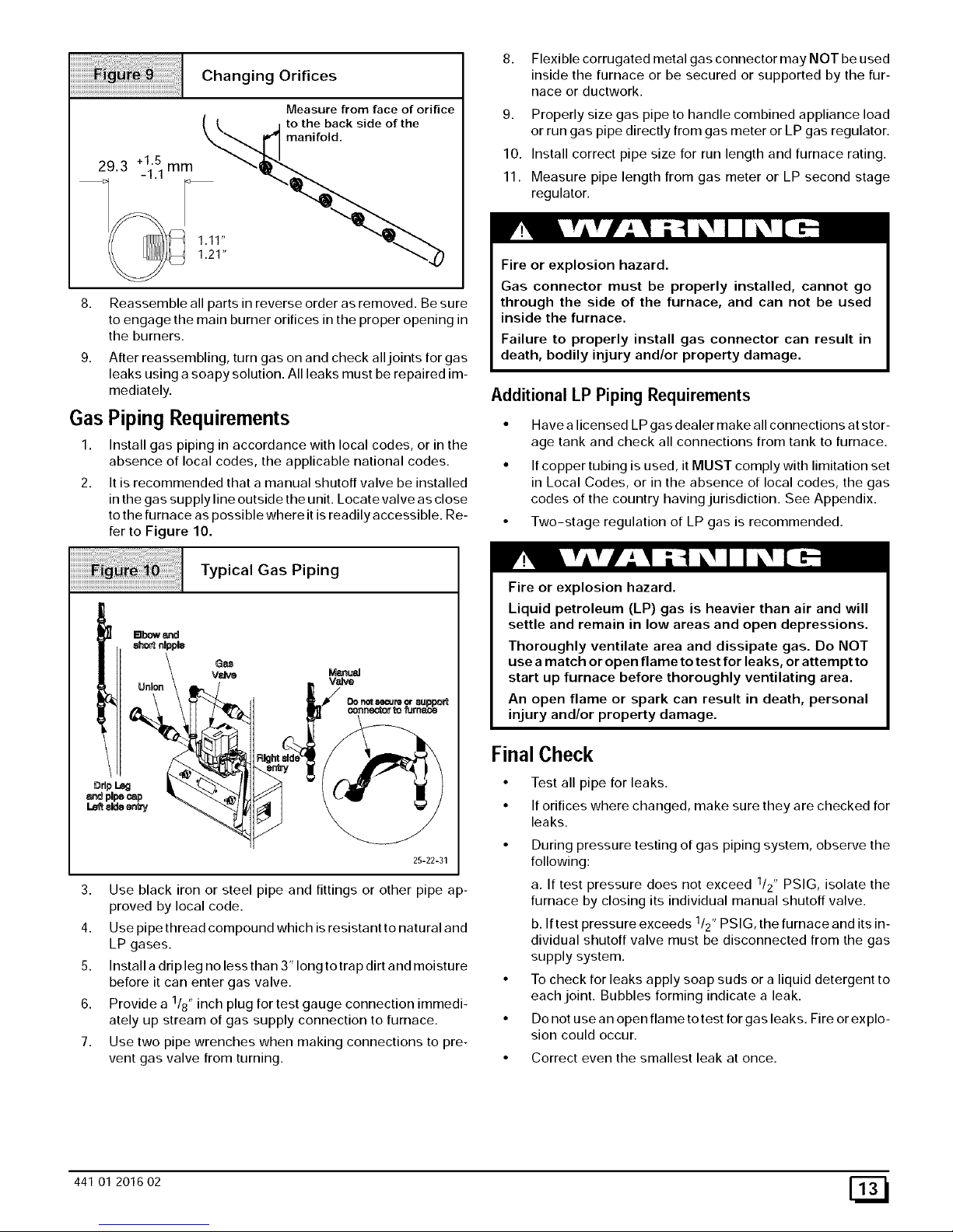
Changing Orifices
Measure from face of orifice
--( -{, j to the back side of the
_,,,",,,,_ mani fold.
8. Reassemble all parts in reverse order as removed. Be sure
to engage the main burner orifices in the proper opening in
the burners.
9. After reassembling, turn gas on and check all joints for gas
leaks using a soapy solution. All leaks must be repaired im-
mediately.
Gas Piping Requirements
1. Install gas piping in accordance with local codes, or in the
absence of local codes, the applicable national codes.
2. It is recommended that a manual shutoff valve be installed
in the gas supply line outside the unit. Locate valve as close
to the furnace as possible where it is readily accessible. Re-
fer to Figure 10.
Typical Gas Piping
25-22-31
3. Use black iron or steel pipe and fittings or other pipe ap-
proved by local code.
4. Use pipe thread compound which is resistant to natural and
LP gases.
5. Install a dripleg no less than 3" long totrap dirt and moisture
before it can enter gas valve.
6. Provide a 118" inch plug for test gauge connection immedi-
ately up stream of gas supply connection to furnace.
7. Use two pipe wrenches when making connections to pre-
vent gas valve from turning.
8. Flexible corrugated metal gas connector may NOT be used
inside the furnace or be secured or supported by the fur-
nace or ductwork.
9. Properly size gas pipe to handle combined appliance load
or run gas pipe directly from gas meter or LP gas regulator.
10. Install correct pipe size for run length and furnace rating.
11. Measure pipe length from gas meter or LP second stage
regulator.
Fire or explosion hazard.
Gas connector must be properly installed, cannot go
through the side of the furnace, and can not be used
inside the furnace.
Failure to properly install gas connector can result in
death, bodily injury and/or property damage.
Additional LP Piping Requirements
• Have a licensed LP gas dealer make all connections at stor-
age tank and check all connections from tank to furnace.
• If copper tubing is used, it MUST comply with limitation set
in Local Codes, or in the absence of local codes, the gas
codes of the country having jurisdiction. See Appendix.
• Two-stage regulation of LP gas is recommended.
Fire or explosion hazard.
Liquid petroleum (LP) gas is heavier than air and will
settle and remain in low areas and open depressions.
Thoroughly ventilate area and dissipate gas. Do NOT
use a match or open fla me to test for lea ks, or attempt to
start up furnace before thoroughly ventilating area.
An open flame or spark can result in death, personal
injury and/or property damage.
Final Check
• Test all pipe for leaks.
• If orifices where changed, make sure they are checked for
leaks.
• During pressure testing of gas piping system, observe the
following:
a. If test pressure does not exceed 1/2" PSIG, isolate the
furnace by closing its individual manual shutoff valve.
b. If test pressure exceeds 1/2" PSIG, the furnace and its in-
dividual shutoff valve must be disconnected from the gas
supply system.
• To check for leaks apply soap suds or a liquid detergent to
each joint. Bubbles forming indicate a leak.
• Do not use an open flame totest for gas leaks. Fire or explo-
sion could occur.
• Correct even the smallest leak at once.
441 01 2016 02 [_
 Loading...