

ICP NTG3/FBF, NTN3/NBF, NTN6/NNE, NTC6/GNE, NDN3/NDF Installation Manual
...
80+
SingleStage
NTG3/FBF& NTC6/GNE
NTN3/NBF& NTN6/NNE
NDN3/NDF& NDN6/GDE
SAFETY REQUIREMENTS
/X
Recognize safety information. This isthe safety-alert symbol/.v X. When you see this symbol on the furnace and in instructions manuals be
alert to the potential for personal injury.
UnderstandthesignalwordsDANGER, WARNING, orOAUTION. Thesewordsareusedwiththesafety-alertsymbol. DANGERidentifiesthe
most serious hazards, those that will result in severe personal injury or death. WARNINGsignifiesahazardthatoouldresultinpersonalinjury
or death. CAUTION is used to identify unsafe practices that could result in minor personal injury or product and property damage.
Installing and servicing heating equipment can be hazardous due to gas and electrical components. Only trained and qualified personnel
should install, repair, or service heating equipment.
Untrained service personnel can perform basic maintenance functions such as cleaning and replacing air filters. All other operations must be
performed by trained service personnel. When working on heating equipment, observe precautions in the literature, on tags, and on labels
attached to or shipped with the unit and other safety precautions that may apply.
Follow all safety codes. In the United States, follow all safety codes including the current edition National Fuel Gas Code (NFGC) NFPA No.
54/ANSIZ223.1. In Canada, refer to the current edition of the National Standard Canada CAN/CGA-B149.1- and .2-M91 Natural Gas and
Propane Installation Codes (NSCNGPIC). Wear safety glasses and work gloves. Have fire extinguisher available during start-up and adjust-
ment procedures and service calls.
These instructions cover minimum requirements and conform to existing national standards and safety codes. In some instances, these
instructions exceed certain local codes and ordinances, especially those that may not have kept up with changing residential construction
practices. We require these instructions as a minimum for a safe installation.
Manufactured by:
International Comfort Products Corporation (USA)
Lewieburg, TN USA 37091
Contents
1.SafeInstallationRequirements................ 3
2.Installation............................... 4
3.Combustion&VentilationAir ................. 7
4.GasVentInstallation ....................... 9
5.HorizontalVenting ......................... 10
6.MasonryChimneyVentingwithOptionalKit ...... 11
7.GasSupplyandPiping...................... 12
8.ElectricalWiring ......................... 15
9. DuctworkandFilter (Upflow/Horizontal)...... 16
10. Ductworkand Filter (Downflow)............ 17
11. ChecksandAdjustments ................. 19
12. FurnaceMaintenance.................... 21
13. TechSupportand Parts .................. 22
Fire or Explosion hazard.
This furnace is not designed for use in mobile
homes, trailers or recreational vehicles.
Such use could result in death, bodily injury
and/or property damage.
Printed in U.S.A. LP1 3/4/2002 441 01 2603 02
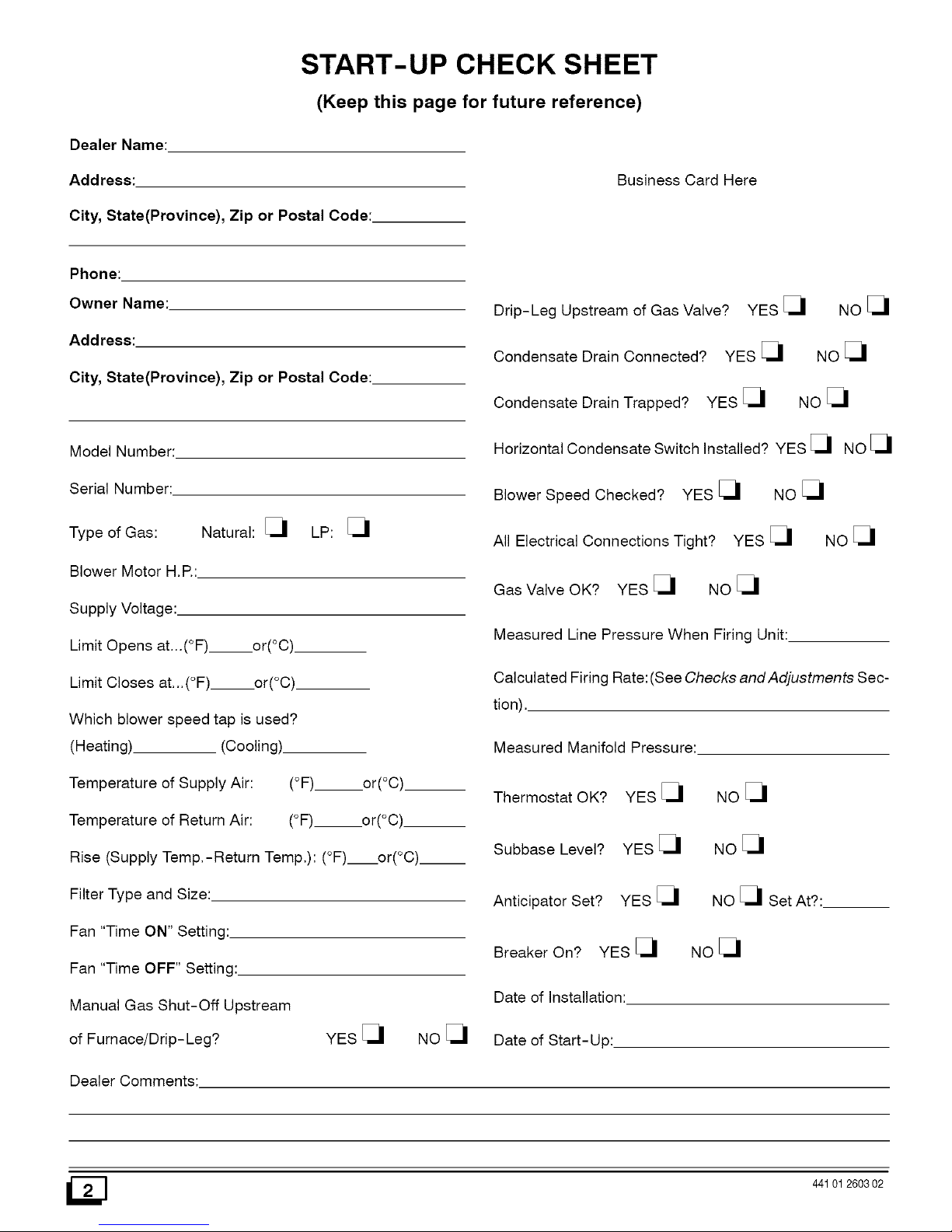
START-UP CHECK SHEET
(Keep this page for future reference)
Dealer Name:
Address:
City, State(Province), Zip or Postal Code:
Business Card Here
Phone:
Owner Name:
Address:
City, State(Province), Zip or Postal Code:
Model Number:
Serial Number:
Natural: [_1 LP: [_1
Type of Gas:
Blower Motor H,P,:
Supply Voltage:.
Limit Opens at...(°F)__.or(°C)
Limit Closes at...(°F) or(°C)
Which blower speed tap is used?
(Heating) (Cooling).
Temperature of Supply Air: (°F) or(°C)
Temperature of Return Air: (°F)___or(°C)
Rise (Supply Temp,-Return Temp,): (°F) or(°C).__
Filter Type and Size:
Fan "Time ON" Setting:
Fan "Time OFF" Setting:
Manual Gas Shut-Off Upstream
of Furnace!Drip-Leg? YES [_1 NO [_1
Dealer Comments:
Drip-Leg Upstream of Gas Valve?
Condensate Drain Connected? YES [_
Condensate Drain Trapped? YES [_
YES _1 NO _1
Noel
NO_1
Horizontal Condensate Switch Installed? YES [_ NO [_
Blower Speed Checked? YES [_ NO [_
All Electrical Connections Tight? YES [_ NO [_
Gas Valve OK? YES [_ NO [_
Measured Line Pressure When Firing Unit:
Calculated Firing Rate:(See Checks and Adjustments Sec-
tion),
Measured Manifold Pressure:
Thermostat OK? YES [_1
Subbase Level? YES [_1
Anticipator Set? YES [_1
Breaker On? YES [_1
Date of Installation:
Date of Start- Up:
NOel
NO_1
NO _1 Set At?:
Noel
I_] 441012603 02

1. Safe Installation Requirements
Installation or repairs made by unqualified persons can
result in hazards to you and others. Installation MUST
conform with local codes or, in the absence of local
codes, with codes of all governmental authorities
having jurisdiction.
The information contained in this manual is intended for
use by a qualified service technician who is experienced
in such work, who is familiar with all precautions and
safety procedures required in such work, and is
equipped with the proper tools and test instruments.
Failure to carefully read and follow all instructions in this
manual can result in furnace malfunction, death,
personal injury and/or property damage.
NOTE: This furnace is design certified by the American Gas
Association and the Canadian Gas Association for installation in
the United States and Canada. Refer to the appropriate codes,
along with this manual, for proper installation.
• This furnace is NOT approved for installation in mobile
homes, trailers or recreation vehicles.
• Do NOT use this furnace as aconstruction heater or to heat
a building that is under construction.
Use only the Type of gas approved for this furnace (see
Rating Plate on unit). Overfiring will result in failure of heat
exchanger and cause dangerous operation, (Furnace can
be converted to LR gas with approved kit.)
• Do NOT use open flame to test for gas leak.
• Ensure adequate combustion and ventilation air is provided
to the furnace.
a.
There can be numerous sources of fire or smoke in a building
or dwelling. Fire or smoke can cause serious bodily injury,
death, and/or property damage. Therefore, in order to alert
people of potentially dangerous fire or smoke, you should
have fire extinguisher and smoke detectors listed by Under-
writers Laboratories installed and maintained in the building
or dwelling (see Note below).
Note: The manufacturer of your furnace does not test any detec-
tors and makes no representations regarding any brand or
type of detector.
C. To ensure safe and efficient operation ofyour unit, you should
do the the following:
1. Thoroughly read this manual and labels on the unit. This
will help you understand how your unit operates and the haz-
ards involved with gas and electricity.
Do not use this unit if any part has been under water. Im-
mediately call a qualified service technician to inspect the
unit and to replace any part of the control system and any gas
control which has been under water.
3. Never obstruct the vent grilles, or any ducts that provide
air to the unit. Air must be provided for proper combustion
and ventilation of flue gases.
Carbon monoxide or "CO" is a colorless and odorless gas
produced when fuel is not burned completely or when the
flame does not receive sufficient oxygen.
• Seal supply and return air ducts.
• The vent system MUST be checked to determine that it is
the correct type and size.
FreezingTemperaturesandYour Structure
• Install correct filter type and size.
• Unit MUST be installed so electrical components are pro-
tected from direct contact with water.
• It is the suggestion of the manufacturer to install fire and
carbon monoxide detectors.
Safety Rules
Your unit is built to provide many years of safe and dependable
service providing it is properly installed and maintained. However,
abuse and/or improper use can shorten the life of the unit and
create hazards for you, the owner.
The U.S. Consumer Product Safety Commission recom-
mends that users of gas-burning appliances install carbon
monoxide detectors. There can be various sources of carbon
monoxide in a building or dwelling. The sources could be
gas-fired clothes dryers, gas cooking stoves, water heaters,
furnaces, gas-fired fireplaces, wood fireplaces, and several
other items. Carbon monoxide can cause serious bodily inju-
ry and/or death. Therefore, to help alert people of potentially
dangerous carbon monoxide levels, you should have carbon
monoxide detectors listed by a nationally recognized agency
(e.g. Underwriters Laboratories or International Approval
Services) installed and maintained in the building or dwelling
(see Note below).
A.
44101 260302
Freeze warning.
Turn off water system.
If your unit remains shut off during cold weather the
water pipes could freeze and burst, resulting in serious
water damage.
Your unit is equipped with safety devices that may keep it from op-
erating if sensors detect abnormal conditions such as clogged ex-
haust flues.
If the structure will be unattended during cold weather you should
take these precautions.
1. Turn off main supply water into the structure and drain the
water lines if possible. Open faucets in appropriate areas.
Have someone check the structure frequently during cold
weather to make sure it is warm enough to prevent pipes
from freezing. Suggest they call a qualified service agency, if
required.
2. Installation
Poison carbon monoxide gas hazard.
Ifthis furnace is replacing a previously common-vented
furnace, it may be necessary to resize the existing vent
line and chimney to prevent oversizing problems for the
other remaining appliances(s). See applicable codes
and Venting and Combustion Air Check in Gas Vent
Installation section.
Failu reto properly vent this furnace or other appliances
can result in death, personal injury and/or property
damage.
Locationand Clearances
If furnace is a replacement, it is usually best to install the furnace
where the old one was. Choose the location or evaluate the exist-
ing location based upon the minimum clearance and furnace di-
mensions (Figure 1, Figure 2 and Figure 3).
CAUTION
Do NOT operate furnace in a corrosive atmosphere contain-
ing chlorine, fluorine or any other damaging chemicals. Re-
fer to Combustion & Ventilation Air section, Contaminated
Combustion Air.
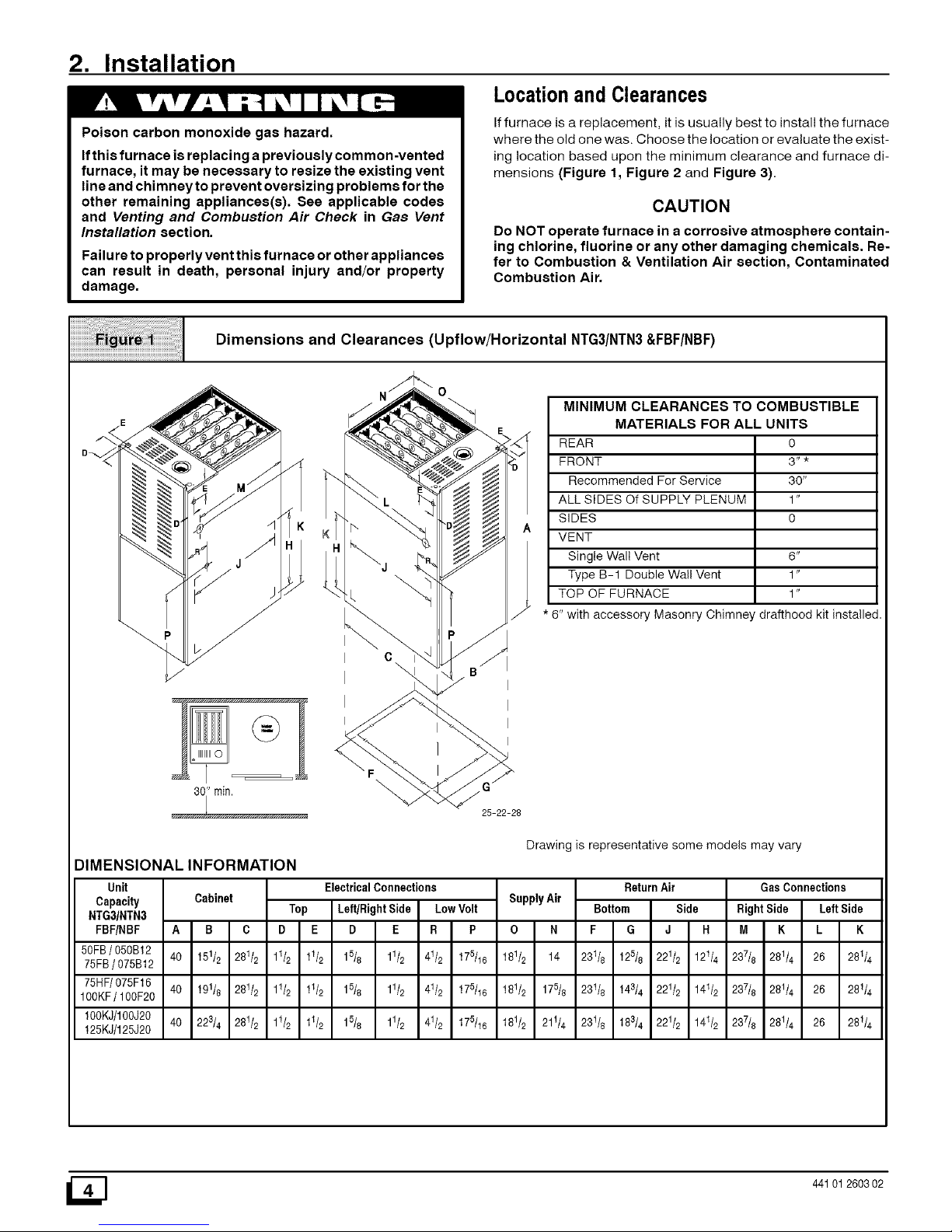
Dimensions and Clearances (Upflow/Horizontal NTG3/NTN3&FBF/NBF)
" rain.
25-22-28
MINIMUM CLEARANCES TO COMBUSTIBLE
MATERIALS FOR ALL UNITS
REAR 0
FRONT 3" *
Recommended For Service 30"
ALL SIDES Of SUPPLY PLENUM 1"
SIDES 0
VENT
Single Wall Vent 6"
Type B-1 Double Wall Vent 1"
TOP OF FURNACE 1"
* 6" with accessory Masonry Chimney drafthood kit installed
Drawing is representative some models may vary
DIMENSIONAL INFORMATION
Unit
Capacity
NTG31NTN3
FBF/NBF A
50FB/ 050B12 40
75FB/ 075B12
75HF/075F16 40
100KF/ 100F20
100KJ/100J20 40
125KJ/125J20
Cabinet
B C
151/2 281/2
191/8 281/2
223/4 281/2
ElectricalConnections
Top Left/RightSide LowVolt
D E D E R P
11/2 11/2 15/8 11/2 41/2 175/16
11/2 11/2 15/8 11/2 41/2 175/16
11/2 11/2 15/8 11/2 41/2 175/16
SupplyAir
O N
181/2 14
181/2 175/8
181/2 211/4
Return Air
Bottom Side
F G J R
231/8 125/8 221/2 121/4
23t/8 143/4 221/2 141/2
231/8 183/4 221/2 141/2
GasConnections
Right Side Left Side
M K L K
237/8 281/4 26 28t/4
237/8 281/4 26 28t/4
237/8 281/4 26 281/4
441012603 02
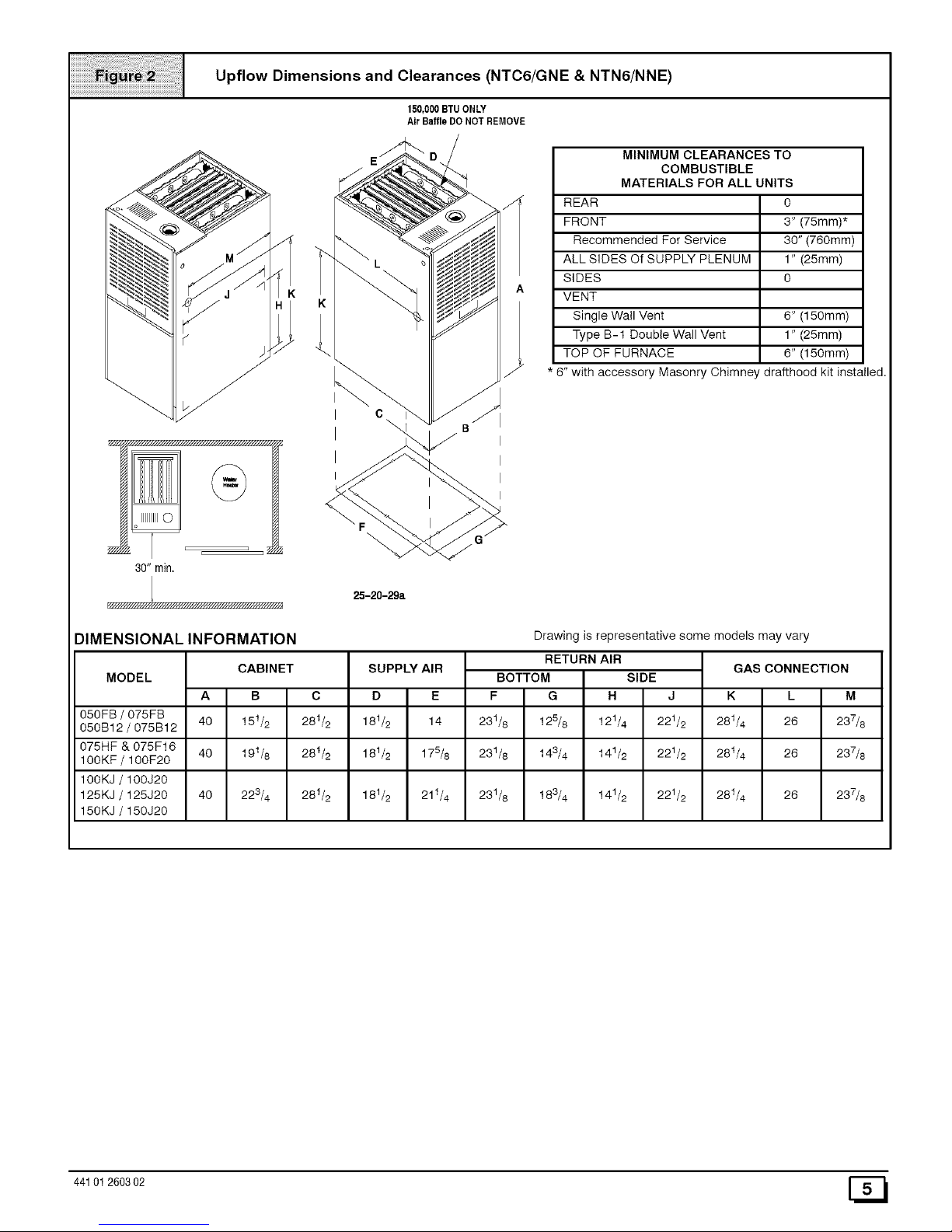
Upflow Dimensions and Clearances (NTC6/GNE & NTN6/NNE)
150,000BTUONLY
Air BaffleDO NOT REMOVE
30" min.
K
K
o
25-20-29a
MINIMUM CLEARANCES TO
COMBUSTIBLE
MATERIALS FOR ALL UNITS
REAR 0
FRONT 3" (75mm)*
Recommended For Service 30" (760mm)
ALL SIDES Of SUPPLY PLENUM 1" (25mm)
SIDES O
VENT
Single Wall Vent 6" (150mm)
Type B-1 Double Wall Vent 1" (25mm)
TOP OF FURNACE 6" (150mm)
* 8" with accessory Masonry Chimney drafthood kit installed.
I
I
I
I
DIMENSIONAL INFORMATION
MODEL
Drawing is representative some models may vary
GAS CONNECTIONCABINET
A I B C
I
40 I 151/2 281/2
40 I 191/8 28t/2
I
40 I 223/4 28t/2
SUPPLY AIR
D I E
181/2 I 14
181/2 I 178/8
RETURN AIR
BOTTOM SIDE
F IG I. IJ
231/8 125/8 I 121/4 221/2
231/8 143/4 I 141/2 221/2
231/8 183/4 141/2 221/2
K I L M
I
050FB / 075FB 281/4 I 26 237/8
050B12 / 075B12
075HF & 075F16 28t/4 I 26 237/8
100KF / 10OF2O
100KJ / 100J2O
125KJ / 125J20 181/2 I 21t/4 28t/4 I 26 237/8
150KJ / 15OJ2O
44101 260302 [_
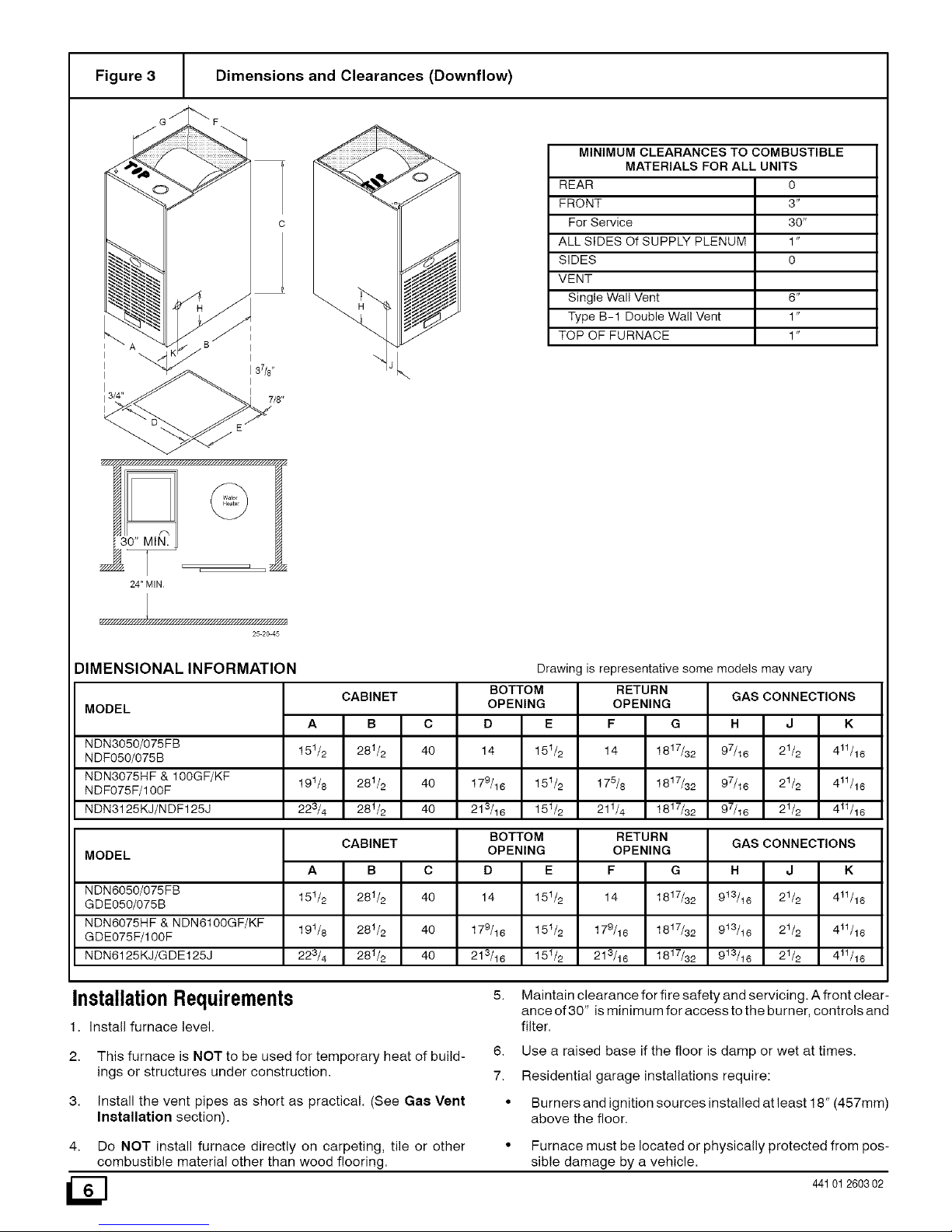
Figure 3 Dimensions and Clearances (Downflow)
I _A ",Jj B I
I3/4" 7/8"
/_ y////////////////////////.'////////////////////////h ,_
MINIMUM CLEARANCES TO COMBUSTIBLE
MATERIALS FOR ALL UNITS
REAR 0
FRONT 3"
For Service 30"
ALL SIDES Of SUPPLY PLENUM 1"
SIDES O
VENT
Single Wall Vent 6"
Type B-1 Double Wall Vent 1"
TOP OF FURNACE 1"
f_
130" MIN.
_, ._ _
24" MIN
25 2O 45
DIMENSIONAL INFORMATION
MODEL
NDN3050/075FB
NDF050/075B
NDN3075HF & 100GF/KF
NDF075F/100F
NDN3125KJ/N DF125J
MODEL
NDN6050/075FB
GDE050/075B
NDN6075HF & NDN6100GF/KF
GDE075F/100F
NDN6125KJ/GDE125J
CABINET
A B C
151/2 281/2 40
191/8 281/2 40
223/4 28t/2 40
BOTTOM
OPENING
F G
14 1817/32
175/8 1817/32
211/4 1817/32
Drawing is representative some models may vary
RETURN
GAS CONNECTIONS
H J K
97/16 21/2 411/16
97/16 21/2 411/16
97/16 21/2 411/16
OPENING
D E
14 151/2
179/16 151/2
213/16 151/2
CABINET
A B C
15t/2 281/2 40
19t/8 281/2 40
223/4 28t/2 40
BOTTOM RETURN
OPENING
F G
14 1817/32
179/16 1817/32
213/16 1817/32
OPENING
D E
14 15t/2
179/16 15 t/2
213/16 151/2
GAS CONNECTIONS
H J K
9t3/t6 21/2 4tl/16
9t3/t6 21/2 4tl/16
913/16 21/2 411/16
InstallationRequirements
1. Install furnace level.
5. Maintain clearance for fire safety and servicing. A front clear-
ance of 30" is minimum for access to the burner, controls and
filter.
2.
3.
This furnace is NOT to be used for temporary heat of build-
ings or structures under construction.
Install the vent pipes as short as practical. (See Gae Vent
Installation section).
6. Use a raised base if the floor is damp or wet at times.
7. Residential garage installations require:
• Burners and ignition sources installed at least 18" (457mm)
above the floor.
4. Do NOT install furnace directly on carpeting, tile or other
combustible material other than wood flooring.
• Furnace must be located or physically protected from pos-
sible damage by a vehicle.
441012603 02
HorizontalFurnaceInstallation
IMPORTANT
NOTE: Inspect unit rating plate to be certain model number be-
gins with "NTN3", "FBF', "NTG3", "NBF", "NTC6", "GNE,
"NTN6" or"NNE". This identifies unit as horizontally mountable.
If unit does NOT bear this designation, you may NOT mount this
unit horizontally. Horizontal furnace may not be mounted on
its back.
If you purchased a horizontally mountable furnace, it can be
installed horizontally in an attic, basement, crawl space, alcove,
or suspended from a ceiling ina basement or utility room in either
a right or left airflow position. See Figure 4.
iiiiiiiii%;:i¸iiiiiiiii!ii;i;i]]i]]i]]iiii;i]]]]ii;i;fill!;;!!i!i!i!i!i!i!i!ill;;;;;;;;;;;;;;;;;;;;;!
ii ii ii ii ii ii ii il ii ii ii ii ii i
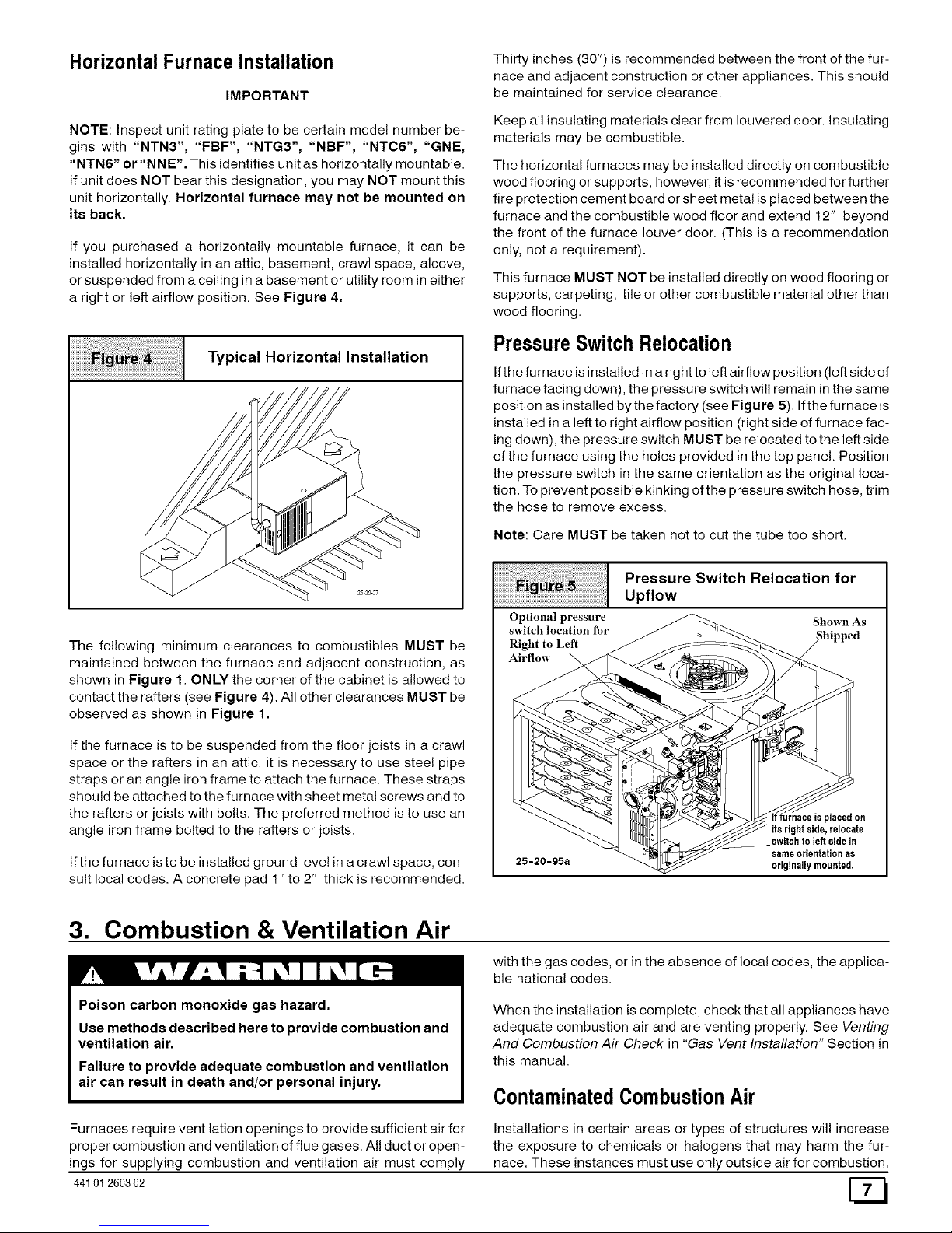
Typical Horizontal Installation
The following minimum clearances to combustibles MUST be
maintained between the furnace and adjacent construction, as
shown in Figure 1. ONLY the corner of the cabinet is allowed to
contact the rafters (see Figure 4). All other clearances MUST be
observed as shown in Figure 1.
If the furnace is to be suspended from the floor joists in a crawl
space or the rafters in an attic, it is necessary to use steel pipe
straps or an angle iron frame to attach the furnace. These straps
should be attached to the furnace with sheet metal screws and to
the rafters or joists with bolts. The preferred method is to use an
angle iron frame bolted to the rafters or joists.
If the furnace is to be installed ground level in a crawl space, con-
sult local codes. A concrete pad 1" to 2" thick is recommended.
Thirty inches (30") is recommended between the front of the fur-
nace and adjacent construction or other appliances. This should
be maintained for service clearance.
Keep all insulating materials clear from Iouvered door. Insulating
materials may be combustible.
The horizontal furnaces may be installed directly on combustible
wood flooring or supports, however, it is recommended for further
fire protection cement board or sheet metal is placed between the
furnace and the combustible wood floor and extend 12" beyond
the front of the furnace louver door. (This is a recommendation
only, not a requirement).
This furnace MUST NOT be installed directly on wood flooring or
supports, carpeting, tile or other combustible material other than
wood flooring.
PressureSwitchRelocation
If the furnace is installed in a right to left airflow position (left side of
furnace facing down), the pressure switch wil! remain in the same
position as installed by the factory (see Figure 5). If the furnace is
installed in a left to right airflow position (right side of furnace fac-
ing down), the pressure switch MUST be relocated to the left side
of the furnace using the holes provided in the top panel. Position
the pressure switch in the same orientation as the original loca-
tion. To prevent possible kinking of the pressure switch hose, trim
the hose to remove excess.
Note: Care MUST be taken not to cut the tube too short.
iiiiiiiiiiiiiiiiiiiiiiiiiiiill¸iiiiiiiii_i%i;!iiiiiiiiiiiiii!;iiii;i;i;i;i;i;i;i;i;i;i;i;i;i;i;i;i;iiiil
iiiiiiiiiiiiiiiiiiiiiii ii i! ! ii J i ; ; i!i!i!i!i!i!i!i!i!i!i!i!i!i!i!i! !!!!i
Optional pressure
switch location for
Right to Left
Airflow
Pressure Switch Relocation for
Upflow
Shown As
25-20-95a
If furnace is placedon
itsrightside, relocate
switchto left sidein
sameorientationas
originallymounted,
3. Combustion & Ventilation Air
Poison carbon monoxide gas hazard.
Use methods described here to provide combustion and
ventilation air.
Failure to provide adequate combustion and ventilation
air can result in death and/or personal injury.
with the gas codes, or in the absence of local codes, the applica-
ble national codes.
When the installation is complete, check that all appliances have
adequate combustion air and are venting properly. See Venting
And Combustion Air Check in "Gas Vent Installation" Section in
this manual.
ContaminatedCombustionAir
Furnaces require ventilation openings to provide sufficient airfor
proper combustion and ventilation of flue gases. All duct or open-
ings for supplying combustion and ventilation air must comply
44101260302
Installations in certain areas or types of structures will increase
the exposure to chemicals or halogens that may harm the fur-
nace. These instances must use only outside air for combustion.
Thefollowingareasortypesofstructuresmaycontainorhaveex-
posuretothesubstanceslistedbelow.Theinstallationmustbe
evaluatedcarefullyasitmaybenecessarytoprovideoutsideair
forcombustion.
• Commercialbuildings.
• Buildingswithindoorpools.
• Furnacesinstalledinlaundryrooms.
• Furnacesinstalledinhobbyorcraftrooms.
• Furnacesinstallednearchemicalstorageareas.
• Permanentwavesolutionsforhair.
• Chlorinatedwaxesandcleaners.
• Chlorinebasedswimmingpoolchemicals.
• Watersofteningchemicals.
• De-icingsaltsorchemicals.
• Carbontetrach!oride.
• Halogentyperefrigerants.
• Cleaningsolvents(suchasperchloroethylene).
• Printinginks,paintremovers,varnishes,etc.
• Hydrochloricacid.
• SulfuricAcid.
• Solventcementsandglues.
• Antistaticfabricsoftenersforclothesdryers.
• Masonryacidwashingmaterials.
ConfinedSpace Installation
NOTE: A confined space is defined as an area with less than 50
cubic feet per 1,000 BTUH input rating for all gas appliances
installed in the area.
AirOpeningsandConnectingDucts
1. Total input rating for all gas appliances MUST be considered
when determining free area of openings.
2. Connect ducts or openings directly to outside.
3. When screens are used to cover openings, the openings
MUST be no smaller than 1/4" mesh.
4. The minimum dimension of rectangular air ducts MUST NOT
be less than 3".
5. When sizing grille or louver, use the free area of opening. If
free area is NOT stamped or marked on grill or louver, as-
sume a 20% free area for wood and 60% for metal.
Requirements
1. Provide confined space with sufficient air for proper combus-
tion and ventilation of flue gases using horizontal or vertical
ducts or openings.
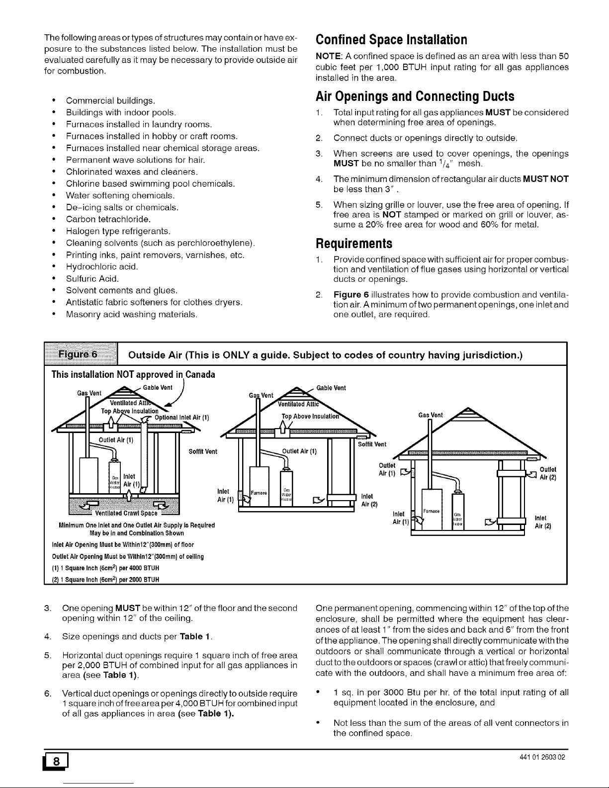
2. Figure 6 illustrates how to provide combustion and ventila-
tion air. A minimum of two permanent openings, one inlet and
one outlet, are required.
Outside Air (This is ONLY a guide. Subject to codes of country having jurisdiction.)
ThisinstallationNOTapprovedinCanada
Gas Vent , Gable Vent Gsl.slVe_le Vent
(f)
/3
i iI I _ ITM
| l] Soffit Vent
soffitvent utletAi''f'II
I _ .LL II I Outlet
Inlet -_'"'"1 [::t;I Inlet
Air(f) d"l I I I _11 • Air(2)
VentilatedCrawlSpace Inlet
MinimumOneInletandOneOutletAirSupplyisRequired Air(1}
MaybeinendCombinationShown
InletAirOpeningMustbeWithinf2"(300mm)offloor
OutletAirOpeningMustbeWithin12"(300mm)ofceiling
(1)1SquareInch(6om2)per4000BTUH
(2)1SquareInch(6cm2)per2000BTUH
iFurn_oe
3a_
Outlet
_] Air(2)
Inlet
Air(2)
3.
4.
5.
6.
One opening MUST be within 12" of the floor and the second
opening within 12" of the ceiling.
Size openings and ducts per Table 1.
Horizontal duct openings require 1 square inch of free area
per 2,000 BTUH of combined input for all gas appliances in
area (see Table 1).
Vertical duct openings or openings directly to outside require
1 square inch of free area per 4,000 BTUH for combined input
of all gas appliances in area (see Table 1).
One permanent opening, commencing within 12" of the top of the
enclosure, shall be permitted where the equipment has clear-
ances of at least 1" from the sides and back and 6" from the front
of the appliance. The opening shall directly communicate with the
outdoors or shall communicate through a vertical or horizontal
duct to the outdoors or spaces (crawl or attic) that freely communi-
cate with the outdoors, and shall have a minimum free area of:
• 1 sq. in per 3000 Btu per hr. of the total input rating of all
equipment located in the enclosure, and
• Not less than the sum of the areas of all vent connectors in
the confined space.
_] 44101260302
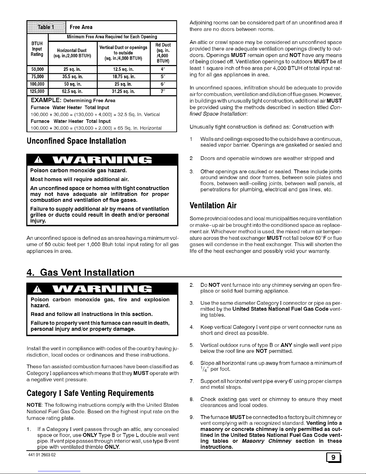
ilFreeAre0
MinimumFreeArea Requiredfor Each Opening
BTUH Rd Duct
VerticalDuctor openings (sq. in.
Input HorizontalDuct to outside
Rating (sq. in./2,OOOBTUH) (sq. in./4,0O0BTUH) /4,000
BTUR)
50,000 25 sq.in. 12.5sq.in. 4"
75,000 35.5 sq. in. 18.75sq. in. 5"
100,000 50sq. in. 25sq. in. 6"
125,000 62.5 sq. in. 31.25 sq.in. 7"
EXAMPLE: Determining Free Area
Furnace Water Heater Total Input
100,000 + 30,000 = (130,000 +4,000) = 32.5 Sq. in. Vertical
Furnace Water Heater Total Input
100,000 + 30,000 = (130,000 + 2,000) = 65 Sq. In. Horizontal
UnconfinedSpaceInstallation
Poison carbon monoxide gas hazard.
Most homes will require additional air.
An unconfined space or homes with tight construction
may not have adequate air infiltration for proper
combustion and ventilation of flue gases.
Failure to supply additional air by means of ventilation
grilles or ducts could result in death and/or personal
injury.
An unconfined space is defined as an area having a minimum vol-
ume of 50 cubic feet per 1,000 Btuh total input rating for all gas
appliances in area.
Adjoining rooms can be considered part of an unconfined area if
there are no doors between rooms.
An attic or crawl space may be considered an unconfined space
provided there are adequate ventilation openings directly to out-
doors. Openings MUST remain open and NOT have any means
of being closed off. Ventilation openings to outdoors MUST be at
least 1 square inch of free area per 4,000 BTUH of total input rat-
ing for all gas appliances in area.
In unconfined spaces, infiltration should be adequate to provide
air for combustion, ventilation and dilution of flue gases. However,
in buildings with unusually tight construction, additional air MUST
be provided using the methods described in section titled Con-
fined Space Installation:
Unusually tight construction is defined as: Construction with
1 Walls and ceilings exposed to the outside have a continuous,
sealed vapor barrier. Openings are gasketed or sealed and
2 Doors and openable windows are weather stripped and
Other openings are caulked or sealed. These include joints
around window and door frames, between sole plates and
floors, between wall-ceiling joints, between wall panels, at
penetrations for plumbing, electrical and gas lines, etc.
VentilationAir
Some provincial codes and local municipalities require ventilation
or make-up air be brought into the conditioned space as replace-
ment air. Whichever method is used, the mixed return air temper-
ature across the heat exchanger MUST not fall below 60 °F or flue
gases will condense in the heat exchanger. This will shorten the
life of the heat exchanger and possibly void your warranty.
4. Gas Vent Installation
Poison carbon monoxide gas, fire and explosion
hazard.
2. Do NOT vent furnace into any chimney serving an open fire-
place or solid fuel burning appliance.
Read and follow all instructions in this section.
Failure to properly vent this furnace can result in death,
personal injury and/or property damage.
Use the same diameter Category ][connector or pipe as per-
mitted by the United States National Fuel Gas Code vent-
ing tables.
Keep vertical Category [vent pipe or vent connector runs as
short and direct as possible.
Install the vent in compliance with codes of the country having ju-
risdiction, local codes or ordinances and these instructions.
These fan assisted combustion furnaces have been classified as
Category ][ appliances which means that they MUST operate with
a negative vent pressure.
Category! SafeVentingRequirements
NOTE: The following instructions comply with the United States
National Fuel Gas Code. Based on the highest input rate on the
furnace rating plate.
1. If a Category [ vent passes through an attic, any concealed
space or floor, use ONLY Type B or Type L double wall vent
pipe. If vent pipe passes through interior wall, use type Bvent
pipe with ventilated thimble ONLY.
44101260302
5. Vertical outdoor runs of type B or ANY single wall vent pipe
below the roof line are NOT permitted.
6. Slope all horizontal runs up away from furnace a minimum of
1/4" per foot.
7. Support all horizontal vent pipe every 6' using proper clamps
and metal straps.
8. Check existing gas vent or chimney to ensure they meet
clearances and local codes.
The furnace MUST be connected to a factory built chimney or
vent complying with a recognized standard. Venting into a
masonry or concrete chimney is only permitted as out-
lined in the United States National Fuel Gas Code vent-
ing tables or Masonry Chimney section in these
instructions.
Poison carbon monoxide gas hazard.
If this furnace is replacing a previously common-
vented furnace, it may be necessary to resize the
existing chimney liner or vent to prevent over sizing
problems for the other remaining appliances(s). See
codes of country having jurisdiction.
Failure to properly vent this furnace or other
appliances can result in property damage, personal
injury and/or death.
Ventingand CombustionAir Check
NOTE: Ifthis installation removes an existing furnace from a vent-
ing system serving one or more other appliances, and to make
sure there is adequate combustion air for all appliances, MAKE
THE FOLLOWING CHECK.
1. Seal any unused openings in the venting system.
2.
Visually inspect the venting system for proper size and hori-
zontal pitch to ensure there is no blockage or restriction, leak-
age, corrosion or other deficiencies which could cause an
unsafe condition.
8.
Insofar as is practical, close all doors and windows and all
doors between the space in which the appliance(s) remain-
ing connected to the venting system are located and other
spaces of the building.
4.
Turn on clothes dryers and any appliance not connected to
the venting system. Turn on any exhaust fans, such as range
hoods and bathroom exhausts, so they will operate at maxi-
mum speed. Do not operate a summer exhaust fan. Close
fireplace dampers.
5. Follow the lighting instructions for each appliance being in-
spected. Adjust thermostat so appliance(s) will operate con-
tinuously.
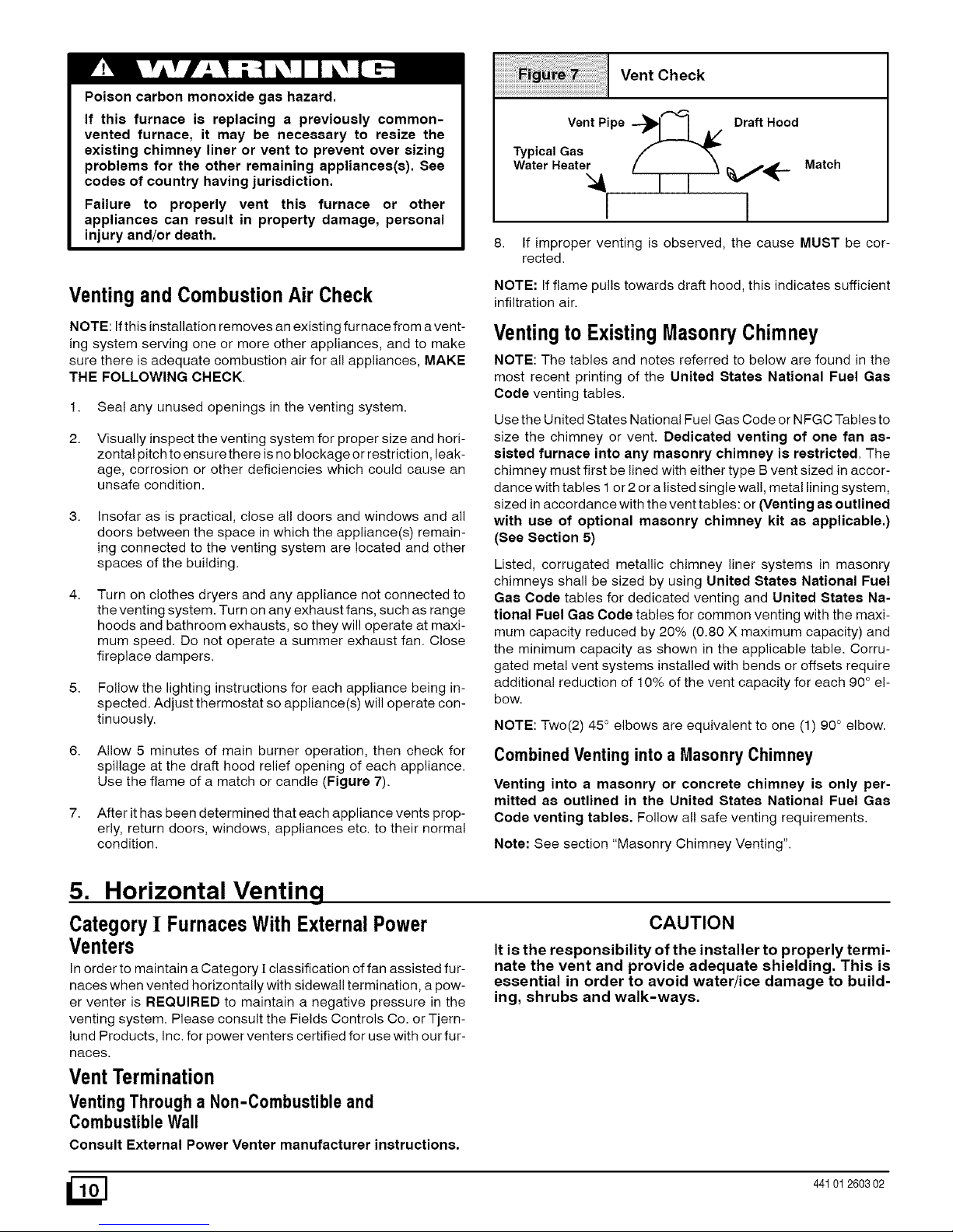
6. Allow 5 minutes of main burner operation, then check for
spillage at the draft hood relief opening of each appliance.
Use the flame of a match or candle (Figure 7).
7. After it has been determined that each appliance vents prop-
erly, return doors, windows, appliances etc. to their normal
condition.
Vent Check
Vent Pipe "_ I A/ Draft Hood
Typical Gas
Water Heater
I 1
Match
8. If improper venting is observed, the cause MUST be cor-
rected.
NOTE: If flame pulls towards draft hood, this indicates sufficient
infiltration air.
Ventingto Existing MasonryChimney
NOTE: The tables and notes referred to below are found in the
most recent printing of the United States National Fuel Gas
Code venting tables.
Use the United States National Fuel Gas Code or NFGC Tables to
size the chimney or vent. Dedicated venting of one fan as-
sisted furnace into any masonry chimney is restricted, The
chimney must first be lined with either type B vent sized in accor-
dance with tables 1 or 2 or a listed single wall, metal lining system,
sized in accordance with the vent tables: or (Venting as outlined
with use of optional masonry chimney kit as applicable.)
(See Section 5)
Listed, corrugated metallic chimney liner systems in masonry
chimneys shall be sized by using United States National Fuel
Gas Code tables for dedicated venting and United States Na-
tional Fuel Gas Code tables for common venting with the maxi-
mum capacity reduced by 20% (0.80 X maximum capacity) and
the minimum capacity as shown in the applicable table. Corru-
gated metal vent systems installed with bends or offsets require
additional reduction of 10% of the vent capacity for each 90 ° e!-
bow.
NOTE: Two(2) 45 ° elbows are equivalent to one (1) 90 ° elbow.
Combined Ventinginto a Masonry Chimney
Venting into a masonry or concrete chimney is only per-
mitted as outlined in the United States National Fuel Gas
Code venting tables. Follow all safe venting requirements.
Note: See section "Masonry Chimney Venting".
5. Horizontal Venting
CategoryI FurnacesWith ExternalPower
Venters
In order to maintain a Category ][classification of fan assisted fur-
naces when vented horizontally with sidewall termination, a pow-
er venter is REQUIRED to maintain a negative pressure in the
venting system. Please consult the Fields Controls Co. or Tjern-
lund Products, Inc. for power venters certified for use with our fur-
naces.
CAUTION
It is the responsibility of the installer to properly termi-
nate the vent and provide adequate shielding, This is
essential in order to avoid water/ice damage to build-
ing, shrubs and walk-ways.
VentTermination
Venting Through a Non-Combustible and
CombustibleWall
Consult External Power Venter manufacturer instructions.
441012603 02
6. Masonry Chimney Venting with Optional Kit Upflow/Horizontal
(USA ONLY) Not recommended for Downflow Furnaces
ChimneyInspection
All masonry chimney construction must conform to Standard
ANSl/NFPA211 and to any state or local codes applicable. The
chimney must be in good condition and a complete investigation
must be conducted prior to installation. If the inspection reveals
damage or abnormal conditions, make necessary repairs or seek
expert help. See "The Chimney Inspection Chart". Measure area
of tile-liner and exact height of chimney.
Connector Type 6.
To reduce flue gas heat loss and the chance of condensate prob- 7.
lems, the vent connector must be double wall Type B vent.
Venting Restrictionsfor ChimneyTypes 8.
Interior Chimney - has no sides exposed to the outside below
the roofline. All installations can be single furnace or common 9.
vented with another draft hood equipped Category I appliance.
Exterior Chimney - has one or more sides exposed to the out-
side below the roof line. All installations must be common vented
only with another draft hood equipped Category I appliance.
I I
lines may cause severe property dama_le.
Optional Masonry Vent Kit 3.
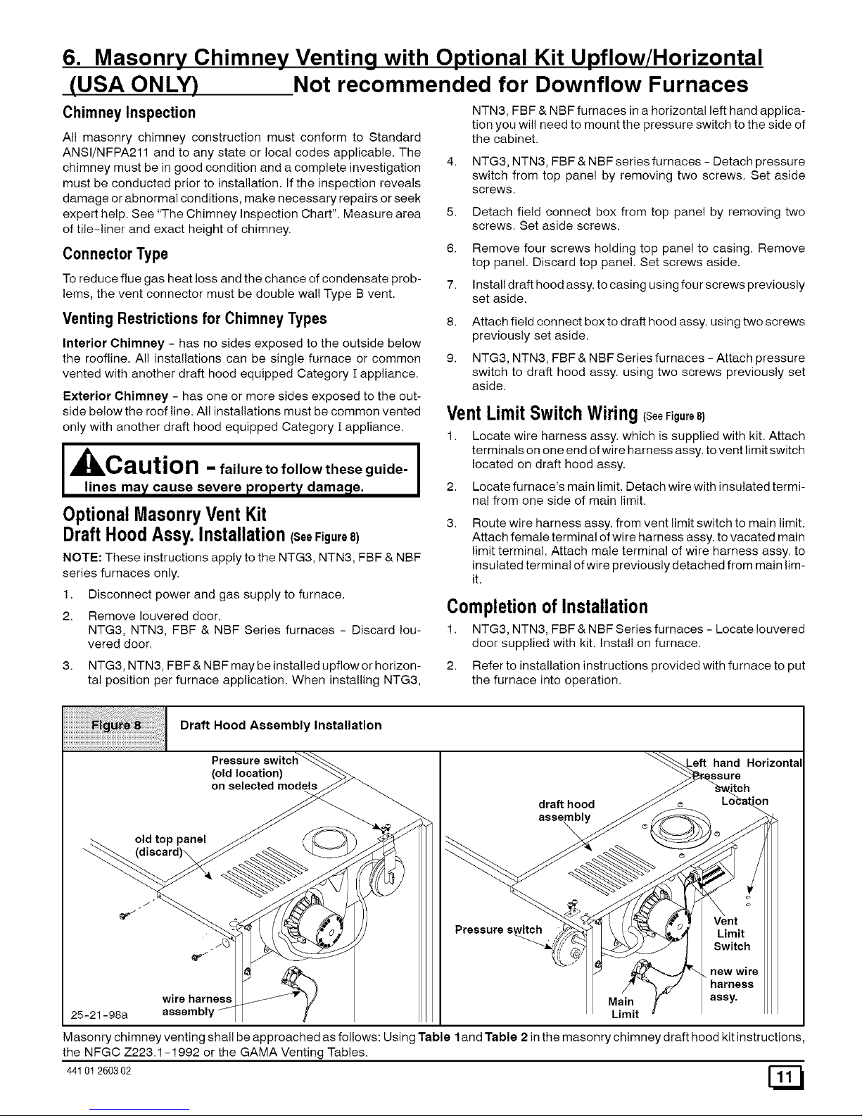
DraftHoodAssy. Installation(SeeFigure8)
NOTE: These instructions apply to the NTG3, NTN3, FBF & NBF
series furnaces only.
1. Disconnect power and gas supply to furnace.
2. Remove Iouvered door.
NTG3, NTN3, FBF & NBF Series furnaces - Discard Iou-
vered door.
NTN3, FBF & NBF furnaces in a horizontal left hand applica-
tion you will need to mount the pressure switch to the side of
the cabinet.
4. NTG3, NTN3, FBF & NBF series furnaces - Detach pressure
switch from top panel by removing two screws. Set aside
screws.
5. Detach field connect box from top panel by removing two
screws. Set aside screws.
Remove four screws holding top panel to casing. Remove
top panel. Discard top panel. Set screws aside.
Install draft hood assy. to casing using four screws previously
set aside.
Attach field connect box to draft hood assy. using two screws
previously set aside.
NTG3, NTN3, FBF & NBF Series furnaces - Attach pressure
switch to draft hood assy. using two screws previously set
aside.
VentLimit SwitchWiring(SeeFigure8)
1. Locate wire harness assy. which is supplied with kit. Attach
terminals on one end of wire harness assy. to vent limit switch
located on draft hood assy.
2. Locate furnace's main limit. Detach wire with insulated termi-
nal from one side of main limit.
Route wire harness assy. from vent limit switch to main limit.
Attach female terminal of wire harness assy. to vacated main
limit terminal. Attach male terminal of wire harness assy. to
insulated terminal of wire previously detached from main lim-
it.
Completionof Installation
1. NTG3, NTN3, FBF & NBF Series furnaces - Locate Iouvered
door supplied with kit. Install on furnace.
3. NTG3, NTN3, FBF & NBF may be installed upflow or horizon-
tal position per furnace application. When installing NTG3,
2. Refer to installation instructions provided with furnace to put
the furnace into operation.
Draft Hood Assembly Installation
Pressure switch_
(oO/dle_cation) "--.._>_
old top panel _ ( _C )) _ >
wire harness _J_%'_
25-21-98a assembly//-
ft hand Horizontal
_ch..
draft hood __ e__._ LOcain
""-_'_ _ _ _ f I_q/ /f_ ! Vent
Pressure s_ _ __...(l__ u_ Limit
/2 ,_"
/ . new wire
. ..;:ro:,:e
Main _" assy.
Limit
Masonry chimney venting shall be approached as follows: Using Table land Table 2 in the masonry chimney draft hood kit instructions,
the NFGC Z223.1-1992 or the GAMA Venting Tables.
44101 260302
7. Gas Supply and Piping
Poison carbon monoxide gas, fire and explosion hazard.
Models designated for Natural Gas are to be used with
Natural Gas ON LY,unless properly converted to use with
LP gas.
Failure to follow these instructions can result in death,
personal injury and/or property damage.
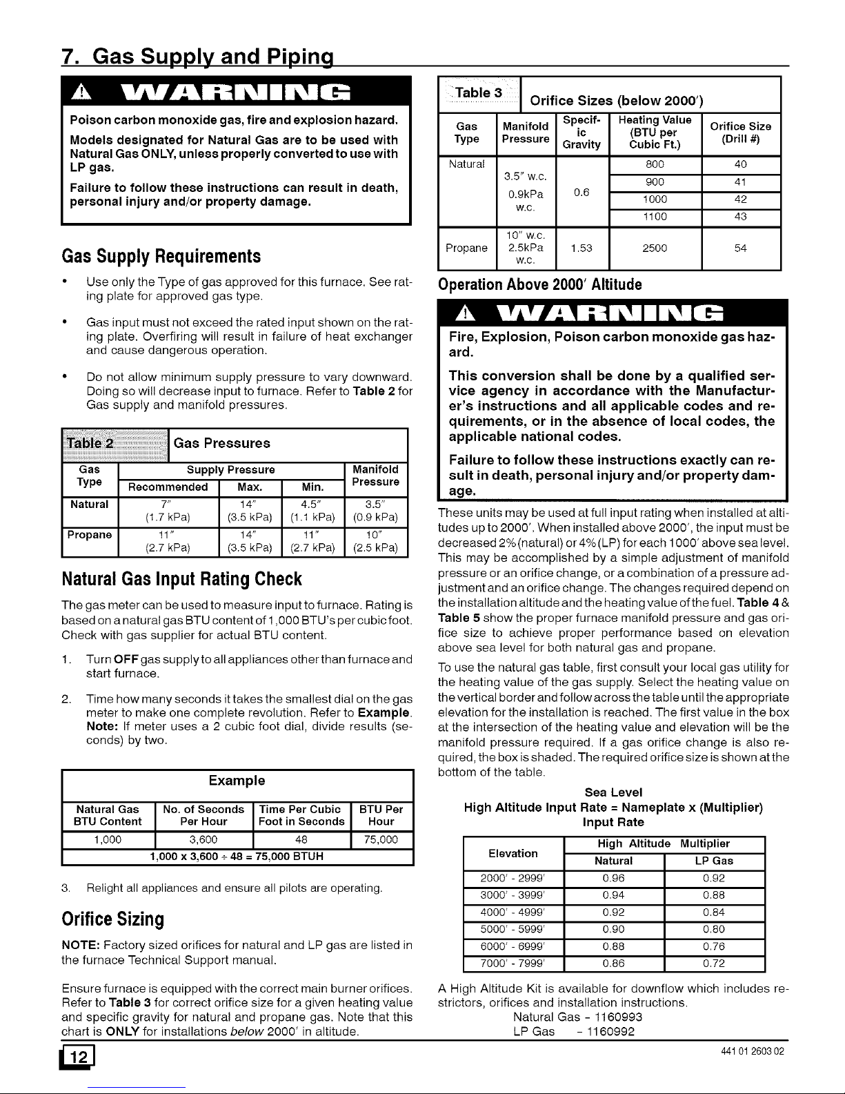
Table 3
Orifice Sizes (below 2000')
Gas Manifold Spacif- HeatingValue
ic (BTU par
Type Pressure Gravity Cubic Ft.)
Natural
Propane
GasSupplyRequirements
80O
3.5" w.c.
90O
0.9kPa 0.6
1000
w.c.
1100
10" w.c.
2.5kPa 1.53
w.c.
2500
Orifice Size
(Drill #)
4O
41
42
43
54
• Use only the Type of gas approved for this furnace. See rat-
ing plate for approved gas type.
OperationAbove 2000' Altitude
Gas input must not exceed the rated input shown on the rat-
ing plate. Overfiring will result in failure of heat exchanger
and cause dangerous operation.
Do not allow minimum supply pressure to vary downward.
Doing so will decrease input to furnace. Refer to Table 2 for
Gas supply and manifold pressures.
Pressures
Gas
Type
Natural
Manifold
Pressure
Supply Pressure
Recommended Max.
7" 14"
(1.7 kPa) (3.5 kPa)
11" 14"
(2.7 kPa) (3.5 kPa)
Min.
4.5" 3.5"
(1,1 kPa) (0.9 kPa)
Propane 11" 10"
(2.7 kPa) (2.5 kPa)
NaturalGas Input RatingCheck
The gas meter can be used to measure input to furnace. Rating is
based on a natural gas BTU content of 1,000 BTU's per cubic foot.
Check with gas supplier for actual BTU content.
1. Turn OFF gas supplyto all appliances otherthan furnace and
start furnace.
2.
Time how many seconds ittakes the smallest dial on the gas
meter to make one complete revolution. Refer to Example.
Note: If meter uses a 2 cubic foot dial, divide results (se-
conds) by two.
Example
Natural Gas No. of Seconds Time Per Cubic BTU Par
BTU Content Per Hour Foot in Seconds Hour
1,000 3,600 48 75,000
1,000 x 3,600 + 48 = 75,000 BTUH
3. Relight all appliances and ensure all pilots are operating.
OrificeSizing
NOTE: Factory sized orifices for natural and LP gas are listed in
the furnace Technical Support manual.
Fire, Explosion, Poison carbon monoxide gas haz-
ard.
This conversion shall be done by a qualified ser-
vice agency in accordance with the Manufactur-
er's instructions and all applicable codes and re-
quirements, or in the absence of local codes, the
applicable national codes.
Failure to follow these instructions exactly can re-
sult in death, personal injury and/or property dam-
age.
These units may be used at full input rating when installed at alti-
tudes up to 2000'. When installed above 2000', the input must be
decreased 2%(natural) or 4%(LP) for each 1000' above sea level.
This may be accomplished by a simple adjustment of manifold
pressure or an orifice change, or a combination of a pressure ad-
justment and an orifice change. The changes required depend on
the installation altitude and the heating value of the fuel. Table 4 &
Table 5 show the proper furnace manifold pressure and gas ori-
fice size to achieve proper performance based on elevation
above sea level for both natural gas and propane.
To use the natural gas table, first consult your local gas utility for
the heating value of the gas supply. Select the heating value on
the vertical border and follow across the table until the appropriate
elevation for the installation is reached. The first value in the box
at the intersection of the heating value and elevation will be the
manifold pressure required. If a gas orifice change is also re-
quired, the box is shaded. The required orifice size is shown atthe
bottom of the table.
Sea Level
High Altitude Input Rate -- Nameplate x (Multiplier)
Elevation
2000'-2999'
3000'-3999'
4000'-4999'
5000'-5999'
6000'-6999'
7000'-7999'
Input Rate
High Altitude Multiplier
Natural LP Gas
0.96 0.92
0.94 0.88
0.92 0.84
0.90 0.80
0.88 0.76
0.86 0.72
Ensure furnace is equipped with the correct main burner orifices.
Refer to Table 3 for correct orifice size for a given heating value
and specific gravity for natural and propane gas. Note that this
chart is ONLY for installations below 2000' in altitude.
/2N
A High Altitude Kit is available for downflow which includes re-
strictors, orifices and installation instructions.
Natural Gas - 1160993
LP Gas - 1160992
44101260302
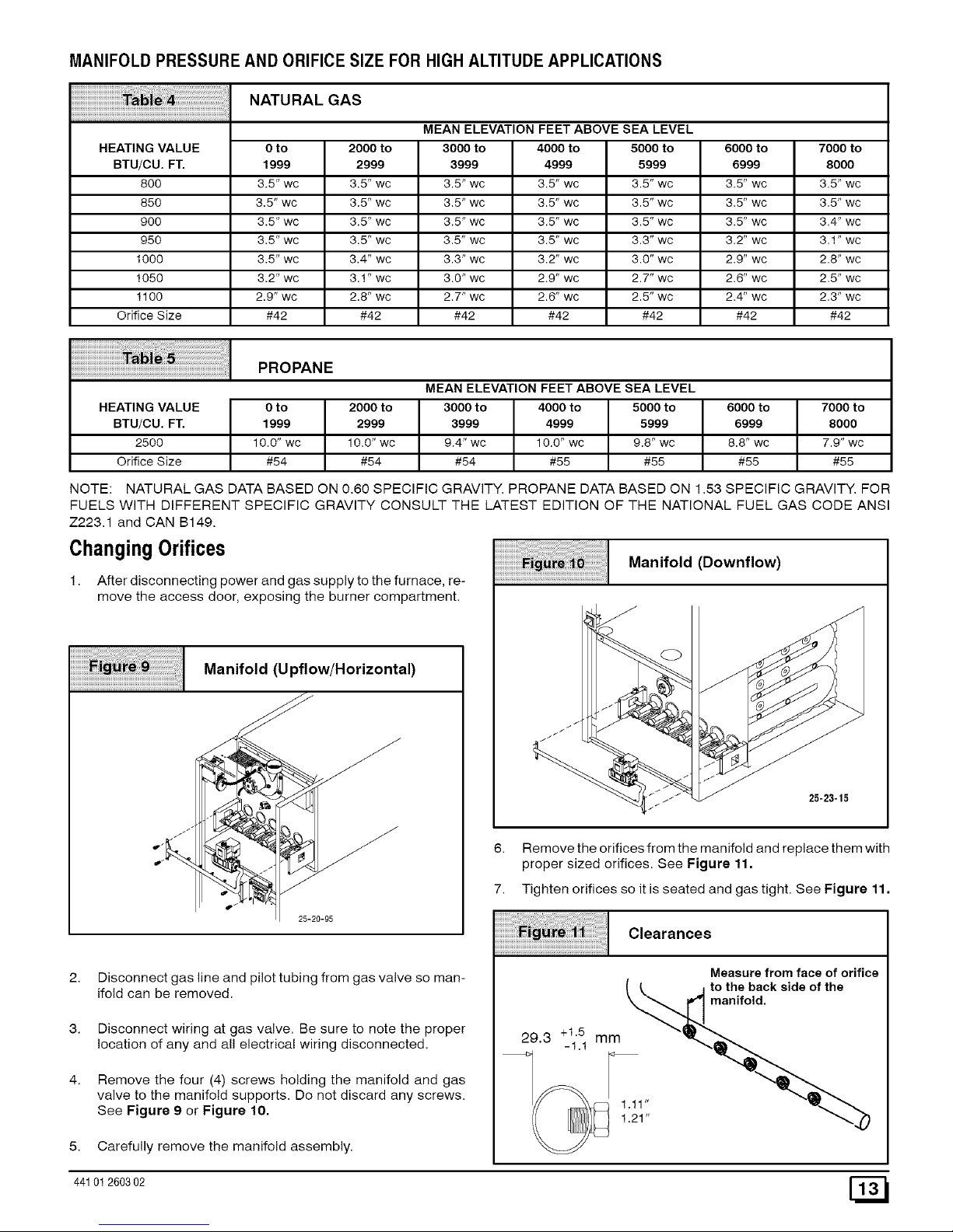
MANIFOLD PRESSUREAND ORIFICESIZE FOR HIGHALTITUDE APPLICATIONS
NATURAL GAS
MEAN ELEVATION FEET ABOVE SEA LEVEL
HEATING VALUE 0 to 2000 to 3000 to 4000 to 5000 to 6000 to 7000 to
BTU/CU. FT. 1999 2999 3999 4999 5999 6999 8000
800 3.5" wc 3.5" wc 3.5" wc 3.5" wc 3.5" wc 3.5" wc 3.5" wc
850 3.5" wc 3.5" wc 3.5" wc 3.5" wc 3.5" wc 3.5" wc 3.5" wc
900 3.5" wc 3.5" wc 3.5" wc 3.5" wc 3.5" wc 3.5" wc 3.4" wc
950 3.5" wc 3.5" wc 3.5" wc 3.5" wc 3.3" wc 3.2" wc 3.1" wc
1000 3.5" wc 3.4" wc 3.3" wc 3.2" wc 3.0" wc 2.9" wc 2.8" wc
1050 3.2" wc 3.1" wc 3.0" wc 2.9" wc 2.7" wc 2.6" wc 2.5" wc
1100 2.9" wc 2.8" wc 2.7" wc 2.6" wc 2.5" wc 2.4" wc 2.3" wc
Orifice Size #42 #42 #42 #42 #42 #42 #42
PROPANE
MEAN ELEVATION FEET ABOVE SEA LEVEL
HEATING VALUE 0 to 2000 to 3000 to 4000 to 5000 to 6000 to 7000 to
BTU/CU. FT. 1999 2999 3999 4999 5999 6999 8000
2500 10.0" wc 10.0" wc 9.4" wc 10.0" wc 9.8" wc 8.8" wc 7.9" wc
Orifice Size #54 #54 #54 #55 #55 #55 #55
NOTE: NATURAL GAS DATA BASED ON 0.60 SPECIFIC GRAVITY. PROPANE DATA BASED ON 1.53 SPECIFIC GRAVITY. FOR
FUELS WITH DIFFERENT SPECIFIC GRAVITY CONSULT THE LATEST EDITION OF THE NATIONAL FUEL GAS CODE ANSI
Z223.1 and CAN B149.
ChangingOrifices
1. After disconnecting power and gas supply to the furnace, re-
move the access door, exposing the burner compartment.
Manifold (Upflow/Horizontal)
jJ_
25-20-95
2.
3.
4.
Disconnect gas line and pilot tubing from gas valve so man-
ifold can be removed.
Disconnect wiring at gas valve. Be sure to note the proper
location of any and all electrical wiring disconnected.
Remove the four (4) screws holding the manifold and gas
valve to the manifold supports. Do not discard any screws.
See Figure 9 or Figure 10,
5. Carefully remove the manifold assembly.
Manifold (Downflow)
/
//
25-23-15
6. Remove the orifices from the manifold and replace them with
proper sized orifices. See Figure 11.
7. Tighten orifices so it is seated and gas tight. See Figure 11.
Clearances
Measure from face of orifice
( _ j to the back side of the
_anifold.
1.21"
44101 260302 [_
8. Reassembleallpartsinreverseorderasremoved.Besureto
engagethemainburnerorificesintheproperopeninginthe
burners.
9. Afterreassembling,turngasonandcheckalljointsforgas
leaksusingasoapysolution.Allleaksmustberepairedim-
mediately.
GasPipingRequirements
1. Install gas piping in accordance with local codes, or in the ab-
sence of local codes, the applicable national codes.
2.
3.
4.
5.
6.
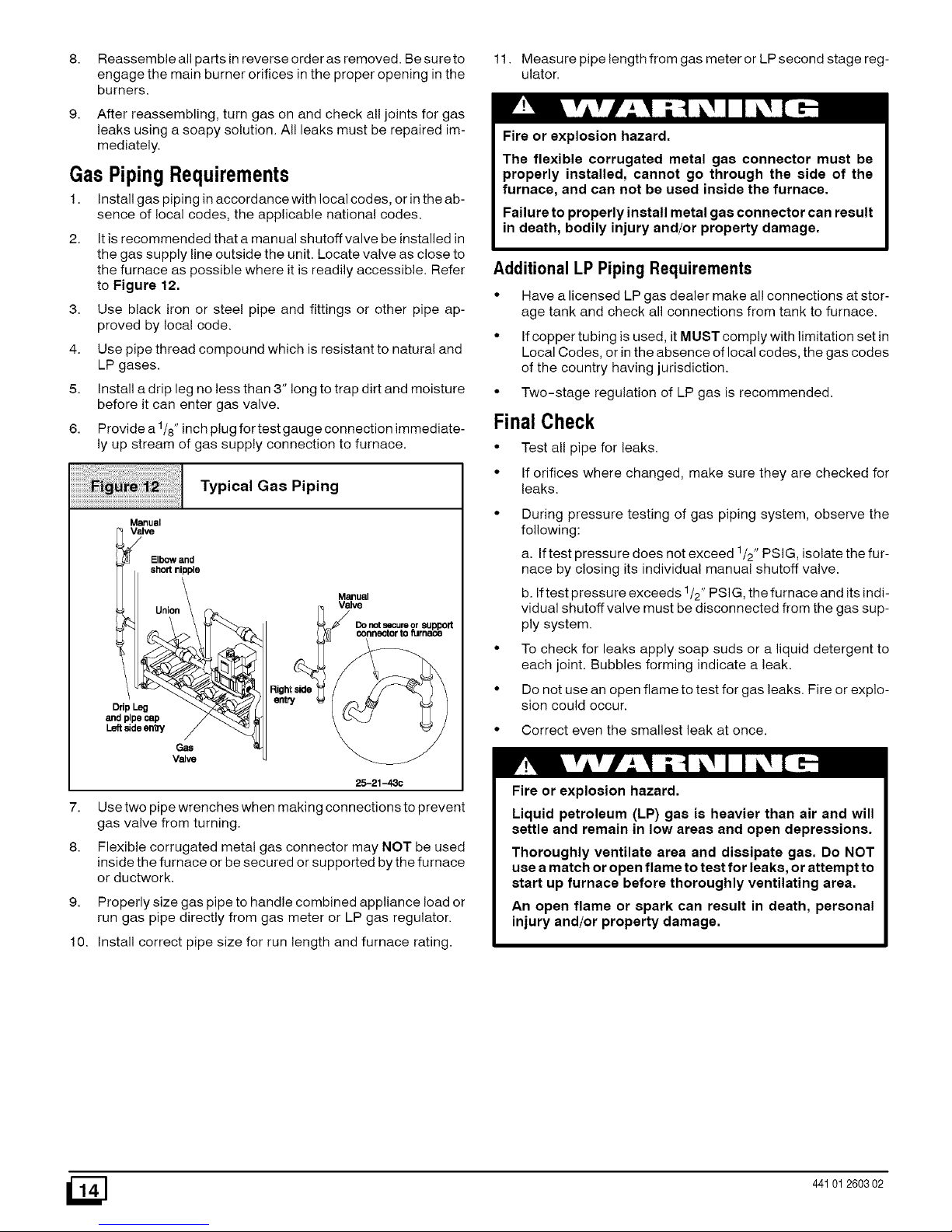
It is recommended that a manual shutoff valve be installed in
the gas supply line outside the unit. Locate valve as close to
the furnace as possible where it is readily accessible. Refer
to Figure 12.
Use black iron or steel pipe and fittings or other pipe ap-
proved by local code.
Use pipe thread compound which is resistant to natural and
LP gases.
Install a drip leg no less than 3" long to trap dirt and moisture
before it can enter gas valve.
Provide a 1/8" inch plug for test gauge connection immediate-
ly up stream of gas supply connection to furnace.
Typical Gas Piping
Manual
V_lve
Elbow and
short nipple
Union _
and pipe cap / _
L_deen_ / _._
Gas
Valve
Manuel
Valve
25-21-43c
7.
8.
Use two pipe wrenches when making connections to prevent
gas valve from turning.
Flexible corrugated metal gas connector may NOT be used
inside the furnace or be secured or supported by the furnace
or ductwork.
9. Properly size gas pipe to handle combined appliance load or
run gas pipe directly from gas meter or LP gas regulator.
10. Install correct pipe size for run length and furnace rating.
11. Measure pipe length from gas meter or LP second stage reg-
ulator.
Fire or explosion hazard.
The flexible corrugated metal gas connector must be
properly installed, cannot go through the side of the
furnace, and can not be used inside the furnace.
Failure to properly install metal gas connector can result
in death, bodily injury and/or property damage.
Additional LP PipingRequirements
• Have a licensed LP gas dealer make all connections at stor-
age tank and check all connections from tank to furnace.
• If copper tubing is used, it MUST comply with limitation set in
Local Codes, or in the absence of local codes, the gas codes
of the country having jurisdiction.
• Two-stage regulation of LP gas is recommended.
FinalCheck
• Test all pipe for leaks.
• If orifices where changed, make sure they are checked for
leaks.
During pressure testing of gas piping system, observe the
following:
a. If test pressure does not exceed 1/2" PSIG, isolate the fur-
nace by closing its individual manual shutoff valve.
b. If test pressure exceeds 1/2" PSIG, the furnace and its indi-
vidual shutoff valve must be disconnected from the gas sup-
ply system.
To check for leaks apply soap suds or a liquid detergent to
each joint. Bubbles forming indicate a leak.
Do not use an open flame to test for gas leaks. Fire or explo-
sion could occur.
• Correct even the smallest leak at once.
Fire or explosion hazard.
Liquid petroleum (LP) gas is heavier than air and will
settle and remain in low areas and open depressions.
Thoroughly ventilate area and dissipate gas. Do NOT
use a match or open flame to test for leaks, or attempt to
start up furnace before thoroughly ventilating area.
An open flame or spark can result in death, personal
injury and/or property damage.
_] 441012603 02

8. Electrical Wiring
Electrical shock hazard.
Turn OFF electrical power at fuse box or service panel
before making any electrical connections and ensure a
proper ground connection is made before connecting
line voltage.
Failure to do so can result in death, personal injury
and/or property damage.
PowerSupplyWiring
The furnace MUST be electrically wired and grounded in accor-
dance with local codes, or in the absence of local codes, the appli-
cable national codes.
Field wiring connections must be made inside the furnace con-
nection box. A suitable strain relief should be used at the point the
wires exit the furnace casing.
Copper conductors shall be used. Line voltage wires should be
sized for the input amps stated on the rating plate. Furnace must
be connected to its own separate circuit.
Thermostat
Thermostat location has an important effect on the operation of
the unit. Follow instructions included with thermostat for correct
mounting and wiring.
Low voltage connections to furnace must be made on terminal
board to fan control. (See Figure 13 or Figure 14)
If cooling is used, the Y from the thermostat must be connected to
the control board Y to energize cooling blower speed.*
Set thermostat heat anticipator in accordance with the Technical
Support Manual.
OptionalEquipment
All wiring from furnace to optional equipment MUST conform to
local codes or, in the absence of local codes, the applicable na-
tional codes. Install wiring in accordance with manufacturer's
instructions.
Humidifier/ElectronicAir Cleaner
The furnace is wired for humidifier and/or electronic air cleaner
connection.
CAUTION
Do NOT exceed 115V/0,8 amp, maximum current load
for both the EAC terminal and the HUM terminal com-
bined.
NOTE: The humidifier will be powered when the furnace is fired
and the circulating air blower comes on. The electronic air cleaner
will be powered anytime the thermostat calls for air movement.
However, the electronic air cleaner is NOT energized during con-
tinuous fan operation controlled by the electronic fan control.
Electrical Connections
(Upflow/Horizontal)
115V, 60Hz
NEUT.
Connection Box
Ground
Thermostat
i i
I i ! _ I
--q I I I
Low Voltage
Termina_Board
25-22-30
115V, 60Hz
NEUT.
Electrical Connections
(Downflow)
Ground
LowVoltage
TerminalBoard
25-21-05b
Control CenterFuse
The 24V circuit contains a 5-amp, automotive-type fuse located
on control center. (See Figure 15) Any electrical shorts of 24V
wiring during installation, service, or maintenance may cause
fuse to blow. If fuse replacement is required, use only a fuse of
identical size (5 amp.)
44101 260302 [_
 Loading...