

Page 1
80+
SingleStage
NTG3/FBF& NTC6/GNE
NTN3/NBF& NTN6/NNE
NDN3/NDF& NDN6/GDE
SAFETY REQUIREMENTS
/X
Recognize safety information. This isthe safety-alert symbol/.v X. When you see this symbol on the furnace and in instructions manuals be
alert to the potential for personal injury.
UnderstandthesignalwordsDANGER, WARNING, orOAUTION. Thesewordsareusedwiththesafety-alertsymbol. DANGERidentifiesthe
most serious hazards, those that will result in severe personal injury or death. WARNINGsignifiesahazardthatoouldresultinpersonalinjury
or death. CAUTION is used to identify unsafe practices that could result in minor personal injury or product and property damage.
Installing and servicing heating equipment can be hazardous due to gas and electrical components. Only trained and qualified personnel
should install, repair, or service heating equipment.
Untrained service personnel can perform basic maintenance functions such as cleaning and replacing air filters. All other operations must be
performed by trained service personnel. When working on heating equipment, observe precautions in the literature, on tags, and on labels
attached to or shipped with the unit and other safety precautions that may apply.
Follow all safety codes. In the United States, follow all safety codes including the current edition National Fuel Gas Code (NFGC) NFPA No.
54/ANSIZ223.1. In Canada, refer to the current edition of the National Standard Canada CAN/CGA-B149.1- and .2-M91 Natural Gas and
Propane Installation Codes (NSCNGPIC). Wear safety glasses and work gloves. Have fire extinguisher available during start-up and adjust-
ment procedures and service calls.
These instructions cover minimum requirements and conform to existing national standards and safety codes. In some instances, these
instructions exceed certain local codes and ordinances, especially those that may not have kept up with changing residential construction
practices. We require these instructions as a minimum for a safe installation.
Manufactured by:
International Comfort Products Corporation (USA)
Lewieburg, TN USA 37091
Contents
1.SafeInstallationRequirements................ 3
2.Installation............................... 4
3.Combustion&VentilationAir ................. 7
4.GasVentInstallation ....................... 9
5.HorizontalVenting ......................... 10
6.MasonryChimneyVentingwithOptionalKit ...... 11
7.GasSupplyandPiping...................... 12
8.ElectricalWiring ......................... 15
9. DuctworkandFilter (Upflow/Horizontal)...... 16
10. Ductworkand Filter (Downflow)............ 17
11. ChecksandAdjustments ................. 19
12. FurnaceMaintenance.................... 21
13. TechSupportand Parts .................. 22
Fire or Explosion hazard.
This furnace is not designed for use in mobile
homes, trailers or recreational vehicles.
Such use could result in death, bodily injury
and/or property damage.
Printed in U.S.A. LP1 3/4/2002 441 01 2603 02
Page 2
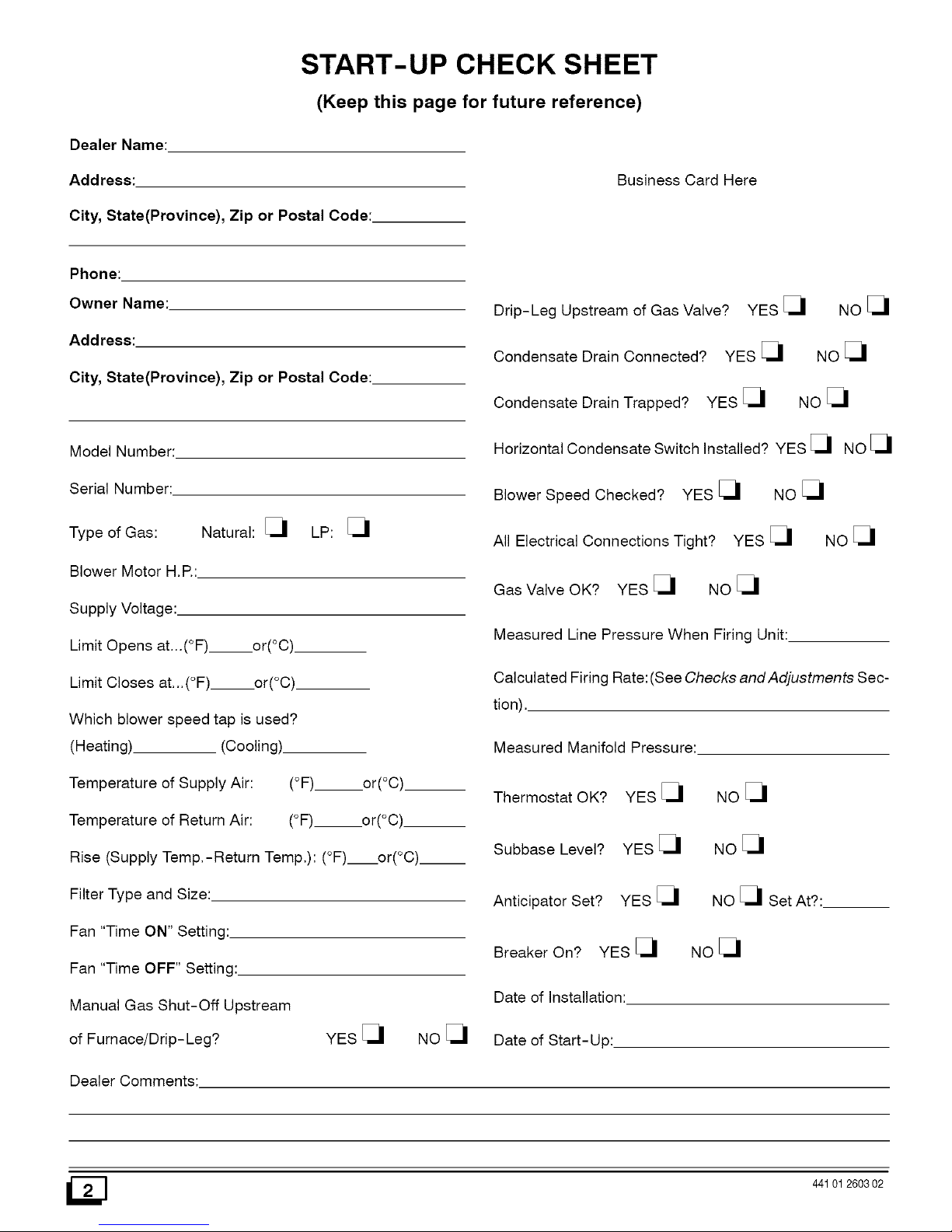
START-UP CHECK SHEET
(Keep this page for future reference)
Dealer Name:
Address:
City, State(Province), Zip or Postal Code:
Business Card Here
Phone:
Owner Name:
Address:
City, State(Province), Zip or Postal Code:
Model Number:
Serial Number:
Natural: [_1 LP: [_1
Type of Gas:
Blower Motor H,P,:
Supply Voltage:.
Limit Opens at...(°F)__.or(°C)
Limit Closes at...(°F) or(°C)
Which blower speed tap is used?
(Heating) (Cooling).
Temperature of Supply Air: (°F) or(°C)
Temperature of Return Air: (°F)___or(°C)
Rise (Supply Temp,-Return Temp,): (°F) or(°C).__
Filter Type and Size:
Fan "Time ON" Setting:
Fan "Time OFF" Setting:
Manual Gas Shut-Off Upstream
of Furnace!Drip-Leg? YES [_1 NO [_1
Dealer Comments:
Drip-Leg Upstream of Gas Valve?
Condensate Drain Connected? YES [_
Condensate Drain Trapped? YES [_
YES _1 NO _1
Noel
NO_1
Horizontal Condensate Switch Installed? YES [_ NO [_
Blower Speed Checked? YES [_ NO [_
All Electrical Connections Tight? YES [_ NO [_
Gas Valve OK? YES [_ NO [_
Measured Line Pressure When Firing Unit:
Calculated Firing Rate:(See Checks and Adjustments Sec-
tion),
Measured Manifold Pressure:
Thermostat OK? YES [_1
Subbase Level? YES [_1
Anticipator Set? YES [_1
Breaker On? YES [_1
Date of Installation:
Date of Start- Up:
NOel
NO_1
NO _1 Set At?:
Noel
I_] 441012603 02
Page 3

1. Safe Installation Requirements
Installation or repairs made by unqualified persons can
result in hazards to you and others. Installation MUST
conform with local codes or, in the absence of local
codes, with codes of all governmental authorities
having jurisdiction.
The information contained in this manual is intended for
use by a qualified service technician who is experienced
in such work, who is familiar with all precautions and
safety procedures required in such work, and is
equipped with the proper tools and test instruments.
Failure to carefully read and follow all instructions in this
manual can result in furnace malfunction, death,
personal injury and/or property damage.
NOTE: This furnace is design certified by the American Gas
Association and the Canadian Gas Association for installation in
the United States and Canada. Refer to the appropriate codes,
along with this manual, for proper installation.
• This furnace is NOT approved for installation in mobile
homes, trailers or recreation vehicles.
• Do NOT use this furnace as aconstruction heater or to heat
a building that is under construction.
Use only the Type of gas approved for this furnace (see
Rating Plate on unit). Overfiring will result in failure of heat
exchanger and cause dangerous operation, (Furnace can
be converted to LR gas with approved kit.)
• Do NOT use open flame to test for gas leak.
• Ensure adequate combustion and ventilation air is provided
to the furnace.
a.
There can be numerous sources of fire or smoke in a building
or dwelling. Fire or smoke can cause serious bodily injury,
death, and/or property damage. Therefore, in order to alert
people of potentially dangerous fire or smoke, you should
have fire extinguisher and smoke detectors listed by Under-
writers Laboratories installed and maintained in the building
or dwelling (see Note below).
Note: The manufacturer of your furnace does not test any detec-
tors and makes no representations regarding any brand or
type of detector.
C. To ensure safe and efficient operation ofyour unit, you should
do the the following:
1. Thoroughly read this manual and labels on the unit. This
will help you understand how your unit operates and the haz-
ards involved with gas and electricity.
Do not use this unit if any part has been under water. Im-
mediately call a qualified service technician to inspect the
unit and to replace any part of the control system and any gas
control which has been under water.
3. Never obstruct the vent grilles, or any ducts that provide
air to the unit. Air must be provided for proper combustion
and ventilation of flue gases.
Carbon monoxide or "CO" is a colorless and odorless gas
produced when fuel is not burned completely or when the
flame does not receive sufficient oxygen.
• Seal supply and return air ducts.
• The vent system MUST be checked to determine that it is
the correct type and size.
FreezingTemperaturesandYour Structure
• Install correct filter type and size.
• Unit MUST be installed so electrical components are pro-
tected from direct contact with water.
• It is the suggestion of the manufacturer to install fire and
carbon monoxide detectors.
Safety Rules
Your unit is built to provide many years of safe and dependable
service providing it is properly installed and maintained. However,
abuse and/or improper use can shorten the life of the unit and
create hazards for you, the owner.
The U.S. Consumer Product Safety Commission recom-
mends that users of gas-burning appliances install carbon
monoxide detectors. There can be various sources of carbon
monoxide in a building or dwelling. The sources could be
gas-fired clothes dryers, gas cooking stoves, water heaters,
furnaces, gas-fired fireplaces, wood fireplaces, and several
other items. Carbon monoxide can cause serious bodily inju-
ry and/or death. Therefore, to help alert people of potentially
dangerous carbon monoxide levels, you should have carbon
monoxide detectors listed by a nationally recognized agency
(e.g. Underwriters Laboratories or International Approval
Services) installed and maintained in the building or dwelling
(see Note below).
A.
44101 260302
Freeze warning.
Turn off water system.
If your unit remains shut off during cold weather the
water pipes could freeze and burst, resulting in serious
water damage.
Your unit is equipped with safety devices that may keep it from op-
erating if sensors detect abnormal conditions such as clogged ex-
haust flues.
If the structure will be unattended during cold weather you should
take these precautions.
1. Turn off main supply water into the structure and drain the
water lines if possible. Open faucets in appropriate areas.
Have someone check the structure frequently during cold
weather to make sure it is warm enough to prevent pipes
from freezing. Suggest they call a qualified service agency, if
required.
Page 4
2. Installation
Poison carbon monoxide gas hazard.
Ifthis furnace is replacing a previously common-vented
furnace, it may be necessary to resize the existing vent
line and chimney to prevent oversizing problems for the
other remaining appliances(s). See applicable codes
and Venting and Combustion Air Check in Gas Vent
Installation section.
Failu reto properly vent this furnace or other appliances
can result in death, personal injury and/or property
damage.
Locationand Clearances
If furnace is a replacement, it is usually best to install the furnace
where the old one was. Choose the location or evaluate the exist-
ing location based upon the minimum clearance and furnace di-
mensions (Figure 1, Figure 2 and Figure 3).
CAUTION
Do NOT operate furnace in a corrosive atmosphere contain-
ing chlorine, fluorine or any other damaging chemicals. Re-
fer to Combustion & Ventilation Air section, Contaminated
Combustion Air.
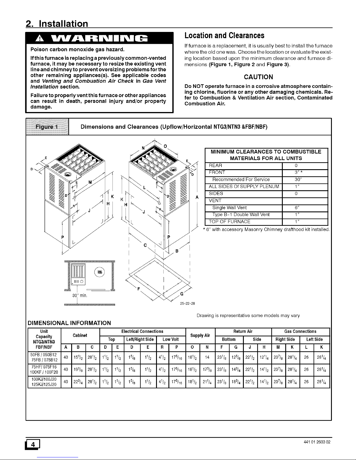
Dimensions and Clearances (Upflow/Horizontal NTG3/NTN3&FBF/NBF)
" rain.
25-22-28
MINIMUM CLEARANCES TO COMBUSTIBLE
MATERIALS FOR ALL UNITS
REAR 0
FRONT 3" *
Recommended For Service 30"
ALL SIDES Of SUPPLY PLENUM 1"
SIDES 0
VENT
Single Wall Vent 6"
Type B-1 Double Wall Vent 1"
TOP OF FURNACE 1"
* 6" with accessory Masonry Chimney drafthood kit installed
Drawing is representative some models may vary
DIMENSIONAL INFORMATION
Unit
Capacity
NTG31NTN3
FBF/NBF A
50FB/ 050B12 40
75FB/ 075B12
75HF/075F16 40
100KF/ 100F20
100KJ/100J20 40
125KJ/125J20
Cabinet
B C
151/2 281/2
191/8 281/2
223/4 281/2
ElectricalConnections
Top Left/RightSide LowVolt
D E D E R P
11/2 11/2 15/8 11/2 41/2 175/16
11/2 11/2 15/8 11/2 41/2 175/16
11/2 11/2 15/8 11/2 41/2 175/16
SupplyAir
O N
181/2 14
181/2 175/8
181/2 211/4
Return Air
Bottom Side
F G J R
231/8 125/8 221/2 121/4
23t/8 143/4 221/2 141/2
231/8 183/4 221/2 141/2
GasConnections
Right Side Left Side
M K L K
237/8 281/4 26 28t/4
237/8 281/4 26 28t/4
237/8 281/4 26 281/4
441012603 02
Page 5
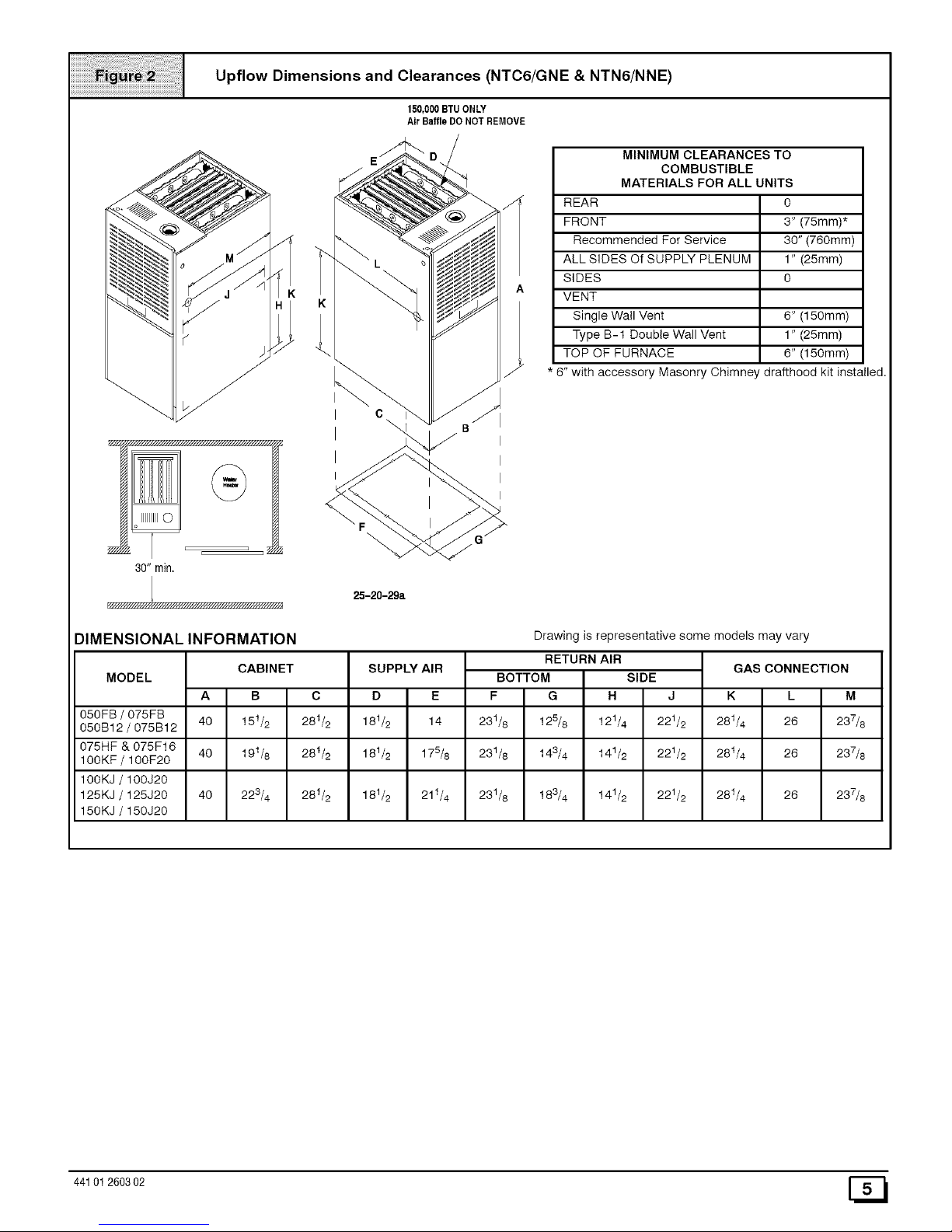
Upflow Dimensions and Clearances (NTC6/GNE & NTN6/NNE)
150,000BTUONLY
Air BaffleDO NOT REMOVE
30" min.
K
K
o
25-20-29a
MINIMUM CLEARANCES TO
COMBUSTIBLE
MATERIALS FOR ALL UNITS
REAR 0
FRONT 3" (75mm)*
Recommended For Service 30" (760mm)
ALL SIDES Of SUPPLY PLENUM 1" (25mm)
SIDES O
VENT
Single Wall Vent 6" (150mm)
Type B-1 Double Wall Vent 1" (25mm)
TOP OF FURNACE 6" (150mm)
* 8" with accessory Masonry Chimney drafthood kit installed.
I
I
I
I
DIMENSIONAL INFORMATION
MODEL
Drawing is representative some models may vary
GAS CONNECTIONCABINET
A I B C
I
40 I 151/2 281/2
40 I 191/8 28t/2
I
40 I 223/4 28t/2
SUPPLY AIR
D I E
181/2 I 14
181/2 I 178/8
RETURN AIR
BOTTOM SIDE
F IG I. IJ
231/8 125/8 I 121/4 221/2
231/8 143/4 I 141/2 221/2
231/8 183/4 141/2 221/2
K I L M
I
050FB / 075FB 281/4 I 26 237/8
050B12 / 075B12
075HF & 075F16 28t/4 I 26 237/8
100KF / 10OF2O
100KJ / 100J2O
125KJ / 125J20 181/2 I 21t/4 28t/4 I 26 237/8
150KJ / 15OJ2O
44101 260302 [_
Page 6
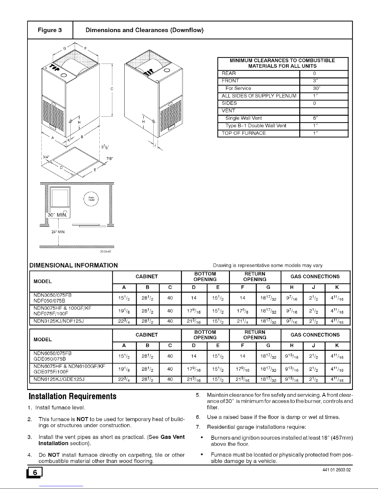
Figure 3 Dimensions and Clearances (Downflow)
I _A ",Jj B I
I3/4" 7/8"
/_ y////////////////////////.'////////////////////////h ,_
MINIMUM CLEARANCES TO COMBUSTIBLE
MATERIALS FOR ALL UNITS
REAR 0
FRONT 3"
For Service 30"
ALL SIDES Of SUPPLY PLENUM 1"
SIDES O
VENT
Single Wall Vent 6"
Type B-1 Double Wall Vent 1"
TOP OF FURNACE 1"
f_
130" MIN.
_, ._ _
24" MIN
25 2O 45
DIMENSIONAL INFORMATION
MODEL
NDN3050/075FB
NDF050/075B
NDN3075HF & 100GF/KF
NDF075F/100F
NDN3125KJ/N DF125J
MODEL
NDN6050/075FB
GDE050/075B
NDN6075HF & NDN6100GF/KF
GDE075F/100F
NDN6125KJ/GDE125J
CABINET
A B C
151/2 281/2 40
191/8 281/2 40
223/4 28t/2 40
BOTTOM
OPENING
F G
14 1817/32
175/8 1817/32
211/4 1817/32
Drawing is representative some models may vary
RETURN
GAS CONNECTIONS
H J K
97/16 21/2 411/16
97/16 21/2 411/16
97/16 21/2 411/16
OPENING
D E
14 151/2
179/16 151/2
213/16 151/2
CABINET
A B C
15t/2 281/2 40
19t/8 281/2 40
223/4 28t/2 40
BOTTOM RETURN
OPENING
F G
14 1817/32
179/16 1817/32
213/16 1817/32
OPENING
D E
14 15t/2
179/16 15 t/2
213/16 151/2
GAS CONNECTIONS
H J K
9t3/t6 21/2 4tl/16
9t3/t6 21/2 4tl/16
913/16 21/2 411/16
InstallationRequirements
1. Install furnace level.
5. Maintain clearance for fire safety and servicing. A front clear-
ance of 30" is minimum for access to the burner, controls and
filter.
2.
3.
This furnace is NOT to be used for temporary heat of build-
ings or structures under construction.
Install the vent pipes as short as practical. (See Gae Vent
Installation section).
6. Use a raised base if the floor is damp or wet at times.
7. Residential garage installations require:
• Burners and ignition sources installed at least 18" (457mm)
above the floor.
4. Do NOT install furnace directly on carpeting, tile or other
combustible material other than wood flooring.
• Furnace must be located or physically protected from pos-
sible damage by a vehicle.
441012603 02
Page 7
HorizontalFurnaceInstallation
IMPORTANT
NOTE: Inspect unit rating plate to be certain model number be-
gins with "NTN3", "FBF', "NTG3", "NBF", "NTC6", "GNE,
"NTN6" or"NNE". This identifies unit as horizontally mountable.
If unit does NOT bear this designation, you may NOT mount this
unit horizontally. Horizontal furnace may not be mounted on
its back.
If you purchased a horizontally mountable furnace, it can be
installed horizontally in an attic, basement, crawl space, alcove,
or suspended from a ceiling ina basement or utility room in either
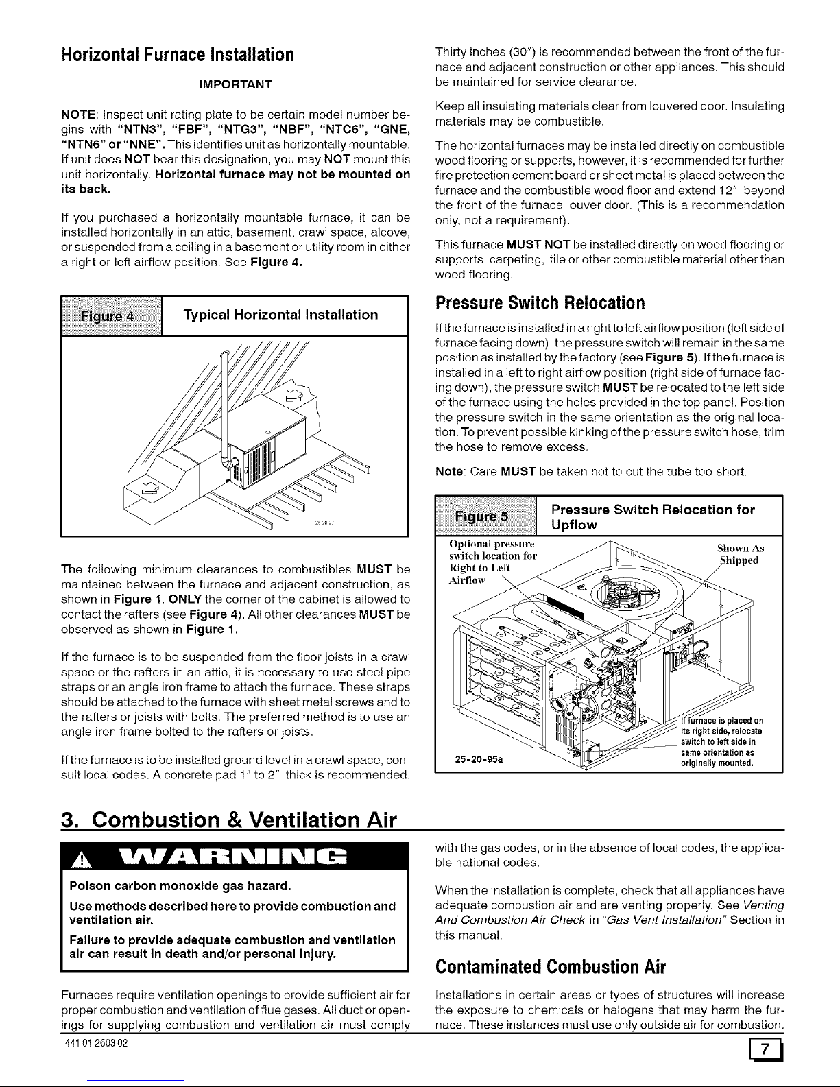
a right or left airflow position. See Figure 4.
iiiiiiiii%;:i¸iiiiiiiii!ii;i;i]]i]]i]]iiii;i]]]]ii;i;fill!;;!!i!i!i!i!i!i!i!ill;;;;;;;;;;;;;;;;;;;;;!
ii ii ii ii ii ii ii il ii ii ii ii ii i
Typical Horizontal Installation
The following minimum clearances to combustibles MUST be
maintained between the furnace and adjacent construction, as
shown in Figure 1. ONLY the corner of the cabinet is allowed to
contact the rafters (see Figure 4). All other clearances MUST be
observed as shown in Figure 1.
If the furnace is to be suspended from the floor joists in a crawl
space or the rafters in an attic, it is necessary to use steel pipe
straps or an angle iron frame to attach the furnace. These straps
should be attached to the furnace with sheet metal screws and to
the rafters or joists with bolts. The preferred method is to use an
angle iron frame bolted to the rafters or joists.
If the furnace is to be installed ground level in a crawl space, con-
sult local codes. A concrete pad 1" to 2" thick is recommended.
Thirty inches (30") is recommended between the front of the fur-
nace and adjacent construction or other appliances. This should
be maintained for service clearance.
Keep all insulating materials clear from Iouvered door. Insulating
materials may be combustible.
The horizontal furnaces may be installed directly on combustible
wood flooring or supports, however, it is recommended for further
fire protection cement board or sheet metal is placed between the
furnace and the combustible wood floor and extend 12" beyond
the front of the furnace louver door. (This is a recommendation
only, not a requirement).
This furnace MUST NOT be installed directly on wood flooring or
supports, carpeting, tile or other combustible material other than
wood flooring.
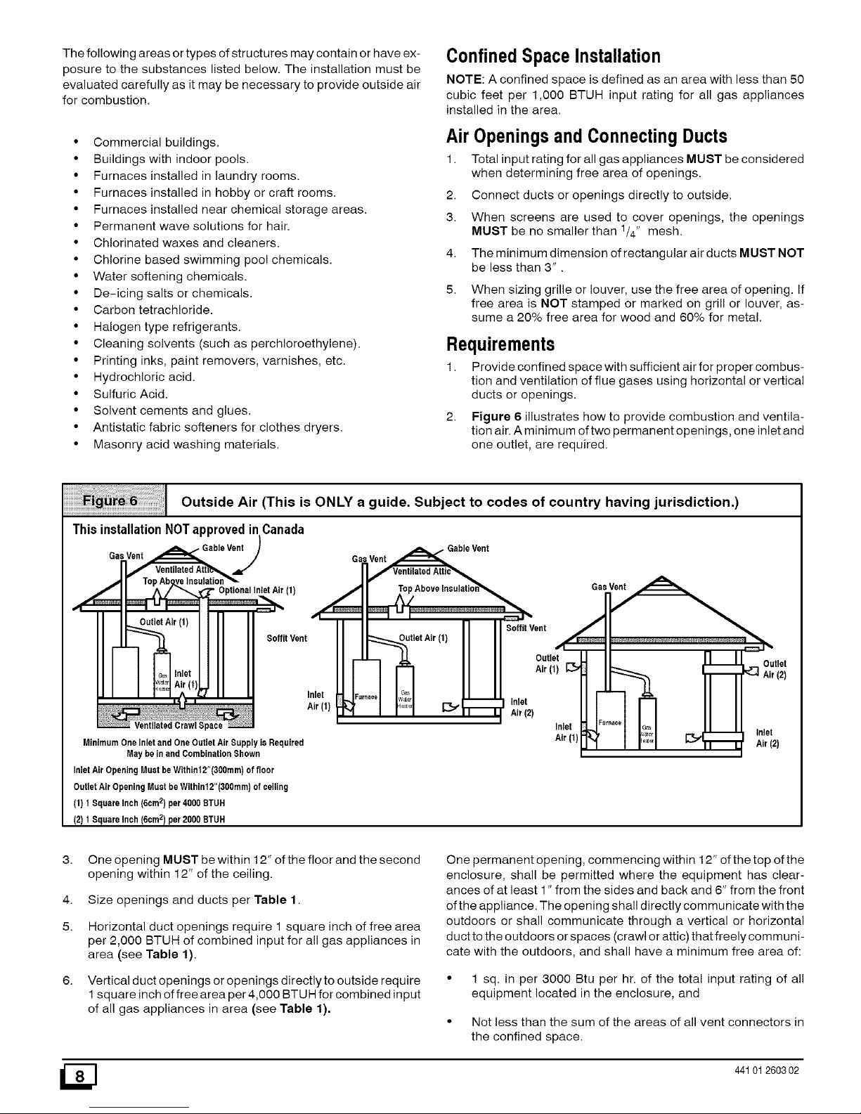
PressureSwitchRelocation
If the furnace is installed in a right to left airflow position (left side of
furnace facing down), the pressure switch wil! remain in the same
position as installed by the factory (see Figure 5). If the furnace is
installed in a left to right airflow position (right side of furnace fac-
ing down), the pressure switch MUST be relocated to the left side
of the furnace using the holes provided in the top panel. Position
the pressure switch in the same orientation as the original loca-
tion. To prevent possible kinking of the pressure switch hose, trim
the hose to remove excess.
Note: Care MUST be taken not to cut the tube too short.
iiiiiiiiiiiiiiiiiiiiiiiiiiiill¸iiiiiiiii_i%i;!iiiiiiiiiiiiii!;iiii;i;i;i;i;i;i;i;i;i;i;i;i;i;i;i;i;iiiil
iiiiiiiiiiiiiiiiiiiiiii ii i! ! ii J i ; ; i!i!i!i!i!i!i!i!i!i!i!i!i!i!i!i! !!!!i
Optional pressure
switch location for
Right to Left
Airflow
Pressure Switch Relocation for
Upflow
Shown As
25-20-95a
If furnace is placedon
itsrightside, relocate
switchto left sidein
sameorientationas
originallymounted,
3. Combustion & Ventilation Air
Poison carbon monoxide gas hazard.
Use methods described here to provide combustion and
ventilation air.
Failure to provide adequate combustion and ventilation
air can result in death and/or personal injury.
with the gas codes, or in the absence of local codes, the applica-
ble national codes.
When the installation is complete, check that all appliances have
adequate combustion air and are venting properly. See Venting
And Combustion Air Check in "Gas Vent Installation" Section in
this manual.
ContaminatedCombustionAir
Furnaces require ventilation openings to provide sufficient airfor
proper combustion and ventilation of flue gases. All duct or open-
ings for supplying combustion and ventilation air must comply
44101260302
Installations in certain areas or types of structures will increase
the exposure to chemicals or halogens that may harm the fur-
nace. These instances must use only outside air for combustion.
Page 8
Thefollowingareasortypesofstructuresmaycontainorhaveex-
posuretothesubstanceslistedbelow.Theinstallationmustbe
evaluatedcarefullyasitmaybenecessarytoprovideoutsideair
forcombustion.
• Commercialbuildings.
• Buildingswithindoorpools.
• Furnacesinstalledinlaundryrooms.
• Furnacesinstalledinhobbyorcraftrooms.
• Furnacesinstallednearchemicalstorageareas.
• Permanentwavesolutionsforhair.
• Chlorinatedwaxesandcleaners.
• Chlorinebasedswimmingpoolchemicals.
• Watersofteningchemicals.
• De-icingsaltsorchemicals.
• Carbontetrach!oride.
• Halogentyperefrigerants.
• Cleaningsolvents(suchasperchloroethylene).
• Printinginks,paintremovers,varnishes,etc.
• Hydrochloricacid.
• SulfuricAcid.
• Solventcementsandglues.
• Antistaticfabricsoftenersforclothesdryers.
• Masonryacidwashingmaterials.
ConfinedSpace Installation
NOTE: A confined space is defined as an area with less than 50
cubic feet per 1,000 BTUH input rating for all gas appliances
installed in the area.
AirOpeningsandConnectingDucts
1. Total input rating for all gas appliances MUST be considered
when determining free area of openings.
2. Connect ducts or openings directly to outside.
3. When screens are used to cover openings, the openings
MUST be no smaller than 1/4" mesh.
4. The minimum dimension of rectangular air ducts MUST NOT
be less than 3".
5. When sizing grille or louver, use the free area of opening. If
free area is NOT stamped or marked on grill or louver, as-
sume a 20% free area for wood and 60% for metal.
Requirements
1. Provide confined space with sufficient air for proper combus-
tion and ventilation of flue gases using horizontal or vertical
ducts or openings.
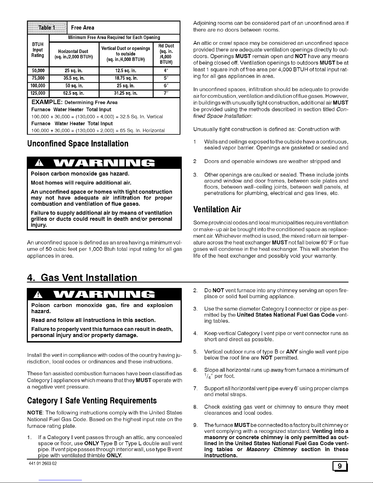
2. Figure 6 illustrates how to provide combustion and ventila-
tion air. A minimum of two permanent openings, one inlet and
one outlet, are required.
Outside Air (This is ONLY a guide. Subject to codes of country having jurisdiction.)
ThisinstallationNOTapprovedinCanada
Gas Vent , Gable Vent Gsl.slVe_le Vent
(f)
/3
i iI I _ ITM
| l] Soffit Vent
soffitvent utletAi''f'II
I _ .LL II I Outlet
Inlet -_'"'"1 [::t;I Inlet
Air(f) d"l I I I _11 • Air(2)
VentilatedCrawlSpace Inlet
MinimumOneInletandOneOutletAirSupplyisRequired Air(1}
MaybeinendCombinationShown
InletAirOpeningMustbeWithinf2"(300mm)offloor
OutletAirOpeningMustbeWithin12"(300mm)ofceiling
(1)1SquareInch(6om2)per4000BTUH
(2)1SquareInch(6cm2)per2000BTUH
iFurn_oe
3a_
Outlet
_] Air(2)
Inlet
Air(2)
3.
4.
5.
6.
One opening MUST be within 12" of the floor and the second
opening within 12" of the ceiling.
Size openings and ducts per Table 1.
Horizontal duct openings require 1 square inch of free area
per 2,000 BTUH of combined input for all gas appliances in
area (see Table 1).
Vertical duct openings or openings directly to outside require
1 square inch of free area per 4,000 BTUH for combined input
of all gas appliances in area (see Table 1).
One permanent opening, commencing within 12" of the top of the
enclosure, shall be permitted where the equipment has clear-
ances of at least 1" from the sides and back and 6" from the front
of the appliance. The opening shall directly communicate with the
outdoors or shall communicate through a vertical or horizontal
duct to the outdoors or spaces (crawl or attic) that freely communi-
cate with the outdoors, and shall have a minimum free area of:
• 1 sq. in per 3000 Btu per hr. of the total input rating of all
equipment located in the enclosure, and
• Not less than the sum of the areas of all vent connectors in
the confined space.
_] 44101260302
Page 9
ilFreeAre0
MinimumFreeArea Requiredfor Each Opening
BTUH Rd Duct
VerticalDuctor openings (sq. in.
Input HorizontalDuct to outside
Rating (sq. in./2,OOOBTUH) (sq. in./4,0O0BTUH) /4,000
BTUR)
50,000 25 sq.in. 12.5sq.in. 4"
75,000 35.5 sq. in. 18.75sq. in. 5"
100,000 50sq. in. 25sq. in. 6"
125,000 62.5 sq. in. 31.25 sq.in. 7"
EXAMPLE: Determining Free Area
Furnace Water Heater Total Input
100,000 + 30,000 = (130,000 +4,000) = 32.5 Sq. in. Vertical
Furnace Water Heater Total Input
100,000 + 30,000 = (130,000 + 2,000) = 65 Sq. In. Horizontal
UnconfinedSpaceInstallation
Poison carbon monoxide gas hazard.
Most homes will require additional air.
An unconfined space or homes with tight construction
may not have adequate air infiltration for proper
combustion and ventilation of flue gases.
Failure to supply additional air by means of ventilation
grilles or ducts could result in death and/or personal
injury.
An unconfined space is defined as an area having a minimum vol-
ume of 50 cubic feet per 1,000 Btuh total input rating for all gas
appliances in area.
Adjoining rooms can be considered part of an unconfined area if
there are no doors between rooms.
An attic or crawl space may be considered an unconfined space
provided there are adequate ventilation openings directly to out-
doors. Openings MUST remain open and NOT have any means
of being closed off. Ventilation openings to outdoors MUST be at
least 1 square inch of free area per 4,000 BTUH of total input rat-
ing for all gas appliances in area.
In unconfined spaces, infiltration should be adequate to provide
air for combustion, ventilation and dilution of flue gases. However,
in buildings with unusually tight construction, additional air MUST
be provided using the methods described in section titled Con-
fined Space Installation:
Unusually tight construction is defined as: Construction with
1 Walls and ceilings exposed to the outside have a continuous,
sealed vapor barrier. Openings are gasketed or sealed and
2 Doors and openable windows are weather stripped and
Other openings are caulked or sealed. These include joints
around window and door frames, between sole plates and
floors, between wall-ceiling joints, between wall panels, at
penetrations for plumbing, electrical and gas lines, etc.
VentilationAir
Some provincial codes and local municipalities require ventilation
or make-up air be brought into the conditioned space as replace-
ment air. Whichever method is used, the mixed return air temper-
ature across the heat exchanger MUST not fall below 60 °F or flue
gases will condense in the heat exchanger. This will shorten the
life of the heat exchanger and possibly void your warranty.
4. Gas Vent Installation
Poison carbon monoxide gas, fire and explosion
hazard.
2. Do NOT vent furnace into any chimney serving an open fire-
place or solid fuel burning appliance.
Read and follow all instructions in this section.
Failure to properly vent this furnace can result in death,
personal injury and/or property damage.
Use the same diameter Category ][connector or pipe as per-
mitted by the United States National Fuel Gas Code vent-
ing tables.
Keep vertical Category [vent pipe or vent connector runs as
short and direct as possible.
Install the vent in compliance with codes of the country having ju-
risdiction, local codes or ordinances and these instructions.
These fan assisted combustion furnaces have been classified as
Category ][ appliances which means that they MUST operate with
a negative vent pressure.
Category! SafeVentingRequirements
NOTE: The following instructions comply with the United States
National Fuel Gas Code. Based on the highest input rate on the
furnace rating plate.
1. If a Category [ vent passes through an attic, any concealed
space or floor, use ONLY Type B or Type L double wall vent
pipe. If vent pipe passes through interior wall, use type Bvent
pipe with ventilated thimble ONLY.
44101260302
5. Vertical outdoor runs of type B or ANY single wall vent pipe
below the roof line are NOT permitted.
6. Slope all horizontal runs up away from furnace a minimum of
1/4" per foot.
7. Support all horizontal vent pipe every 6' using proper clamps
and metal straps.
8. Check existing gas vent or chimney to ensure they meet
clearances and local codes.
The furnace MUST be connected to a factory built chimney or
vent complying with a recognized standard. Venting into a
masonry or concrete chimney is only permitted as out-
lined in the United States National Fuel Gas Code vent-
ing tables or Masonry Chimney section in these
instructions.
Page 10
Poison carbon monoxide gas hazard.
If this furnace is replacing a previously common-
vented furnace, it may be necessary to resize the
existing chimney liner or vent to prevent over sizing
problems for the other remaining appliances(s). See
codes of country having jurisdiction.
Failure to properly vent this furnace or other
appliances can result in property damage, personal
injury and/or death.
Ventingand CombustionAir Check
NOTE: Ifthis installation removes an existing furnace from a vent-
ing system serving one or more other appliances, and to make
sure there is adequate combustion air for all appliances, MAKE
THE FOLLOWING CHECK.
1. Seal any unused openings in the venting system.
2.
Visually inspect the venting system for proper size and hori-
zontal pitch to ensure there is no blockage or restriction, leak-
age, corrosion or other deficiencies which could cause an
unsafe condition.
8.
Insofar as is practical, close all doors and windows and all
doors between the space in which the appliance(s) remain-
ing connected to the venting system are located and other
spaces of the building.
4.
Turn on clothes dryers and any appliance not connected to
the venting system. Turn on any exhaust fans, such as range
hoods and bathroom exhausts, so they will operate at maxi-
mum speed. Do not operate a summer exhaust fan. Close
fireplace dampers.
5. Follow the lighting instructions for each appliance being in-
spected. Adjust thermostat so appliance(s) will operate con-
tinuously.
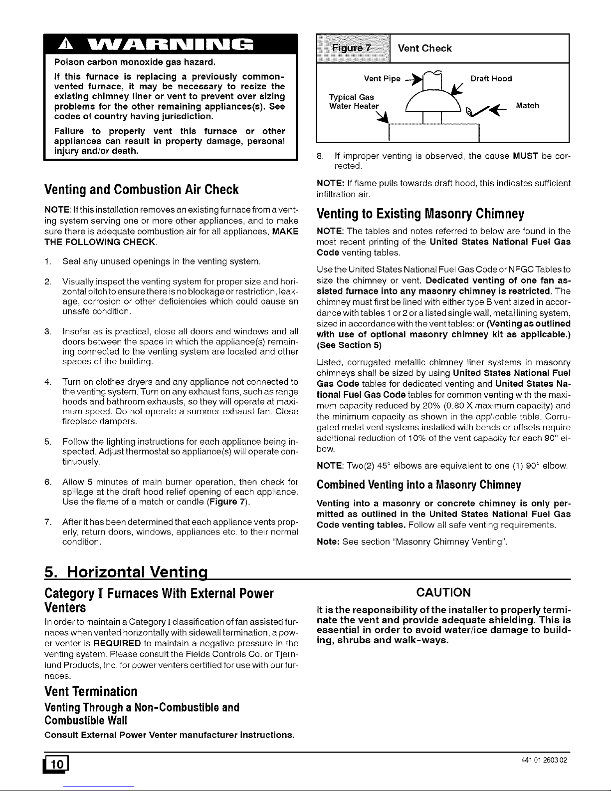
6. Allow 5 minutes of main burner operation, then check for
spillage at the draft hood relief opening of each appliance.
Use the flame of a match or candle (Figure 7).
7. After it has been determined that each appliance vents prop-
erly, return doors, windows, appliances etc. to their normal
condition.
Vent Check
Vent Pipe "_ I A/ Draft Hood
Typical Gas
Water Heater
I 1
Match
8. If improper venting is observed, the cause MUST be cor-
rected.
NOTE: If flame pulls towards draft hood, this indicates sufficient
infiltration air.
Ventingto Existing MasonryChimney
NOTE: The tables and notes referred to below are found in the
most recent printing of the United States National Fuel Gas
Code venting tables.
Use the United States National Fuel Gas Code or NFGC Tables to
size the chimney or vent. Dedicated venting of one fan as-
sisted furnace into any masonry chimney is restricted, The
chimney must first be lined with either type B vent sized in accor-
dance with tables 1 or 2 or a listed single wall, metal lining system,
sized in accordance with the vent tables: or (Venting as outlined
with use of optional masonry chimney kit as applicable.)
(See Section 5)
Listed, corrugated metallic chimney liner systems in masonry
chimneys shall be sized by using United States National Fuel
Gas Code tables for dedicated venting and United States Na-
tional Fuel Gas Code tables for common venting with the maxi-
mum capacity reduced by 20% (0.80 X maximum capacity) and
the minimum capacity as shown in the applicable table. Corru-
gated metal vent systems installed with bends or offsets require
additional reduction of 10% of the vent capacity for each 90 ° e!-
bow.
NOTE: Two(2) 45 ° elbows are equivalent to one (1) 90 ° elbow.
Combined Ventinginto a Masonry Chimney
Venting into a masonry or concrete chimney is only per-
mitted as outlined in the United States National Fuel Gas
Code venting tables. Follow all safe venting requirements.
Note: See section "Masonry Chimney Venting".
5. Horizontal Venting
CategoryI FurnacesWith ExternalPower
Venters
In order to maintain a Category ][classification of fan assisted fur-
naces when vented horizontally with sidewall termination, a pow-
er venter is REQUIRED to maintain a negative pressure in the
venting system. Please consult the Fields Controls Co. or Tjern-
lund Products, Inc. for power venters certified for use with our fur-
naces.
CAUTION
It is the responsibility of the installer to properly termi-
nate the vent and provide adequate shielding, This is
essential in order to avoid water/ice damage to build-
ing, shrubs and walk-ways.
VentTermination
Venting Through a Non-Combustible and
CombustibleWall
Consult External Power Venter manufacturer instructions.
441012603 02
Page 11
6. Masonry Chimney Venting with Optional Kit Upflow/Horizontal
(USA ONLY) Not recommended for Downflow Furnaces
ChimneyInspection
All masonry chimney construction must conform to Standard
ANSl/NFPA211 and to any state or local codes applicable. The
chimney must be in good condition and a complete investigation
must be conducted prior to installation. If the inspection reveals
damage or abnormal conditions, make necessary repairs or seek
expert help. See "The Chimney Inspection Chart". Measure area
of tile-liner and exact height of chimney.
Connector Type 6.
To reduce flue gas heat loss and the chance of condensate prob- 7.
lems, the vent connector must be double wall Type B vent.
Venting Restrictionsfor ChimneyTypes 8.
Interior Chimney - has no sides exposed to the outside below
the roofline. All installations can be single furnace or common 9.
vented with another draft hood equipped Category I appliance.
Exterior Chimney - has one or more sides exposed to the out-
side below the roof line. All installations must be common vented
only with another draft hood equipped Category I appliance.
I I
lines may cause severe property dama_le.
Optional Masonry Vent Kit 3.
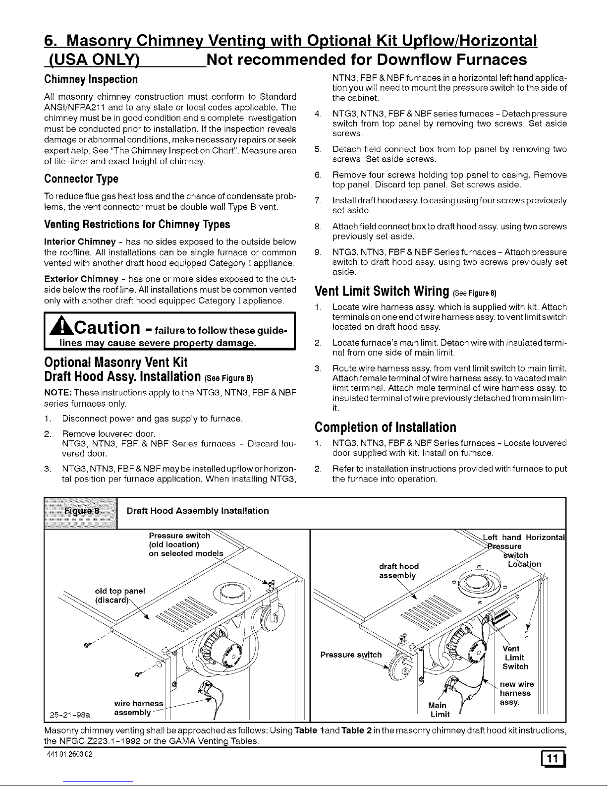
DraftHoodAssy. Installation(SeeFigure8)
NOTE: These instructions apply to the NTG3, NTN3, FBF & NBF
series furnaces only.
1. Disconnect power and gas supply to furnace.
2. Remove Iouvered door.
NTG3, NTN3, FBF & NBF Series furnaces - Discard Iou-
vered door.
NTN3, FBF & NBF furnaces in a horizontal left hand applica-
tion you will need to mount the pressure switch to the side of
the cabinet.
4. NTG3, NTN3, FBF & NBF series furnaces - Detach pressure
switch from top panel by removing two screws. Set aside
screws.
5. Detach field connect box from top panel by removing two
screws. Set aside screws.
Remove four screws holding top panel to casing. Remove
top panel. Discard top panel. Set screws aside.
Install draft hood assy. to casing using four screws previously
set aside.
Attach field connect box to draft hood assy. using two screws
previously set aside.
NTG3, NTN3, FBF & NBF Series furnaces - Attach pressure
switch to draft hood assy. using two screws previously set
aside.
VentLimit SwitchWiring(SeeFigure8)
1. Locate wire harness assy. which is supplied with kit. Attach
terminals on one end of wire harness assy. to vent limit switch
located on draft hood assy.
2. Locate furnace's main limit. Detach wire with insulated termi-
nal from one side of main limit.
Route wire harness assy. from vent limit switch to main limit.
Attach female terminal of wire harness assy. to vacated main
limit terminal. Attach male terminal of wire harness assy. to
insulated terminal of wire previously detached from main lim-
it.
Completionof Installation
1. NTG3, NTN3, FBF & NBF Series furnaces - Locate Iouvered
door supplied with kit. Install on furnace.
3. NTG3, NTN3, FBF & NBF may be installed upflow or horizon-
tal position per furnace application. When installing NTG3,
2. Refer to installation instructions provided with furnace to put
the furnace into operation.
Draft Hood Assembly Installation
Pressure switch_
(oO/dle_cation) "--.._>_
old top panel _ ( _C )) _ >
wire harness _J_%'_
25-21-98a assembly//-
ft hand Horizontal
_ch..
draft hood __ e__._ LOcain
""-_'_ _ _ _ f I_q/ /f_ ! Vent
Pressure s_ _ __...(l__ u_ Limit
/2 ,_"
/ . new wire
. ..;:ro:,:e
Main _" assy.
Limit
Masonry chimney venting shall be approached as follows: Using Table land Table 2 in the masonry chimney draft hood kit instructions,
the NFGC Z223.1-1992 or the GAMA Venting Tables.
44101 260302
Page 12
7. Gas Supply and Piping
Poison carbon monoxide gas, fire and explosion hazard.
Models designated for Natural Gas are to be used with
Natural Gas ON LY,unless properly converted to use with
LP gas.
Failure to follow these instructions can result in death,
personal injury and/or property damage.
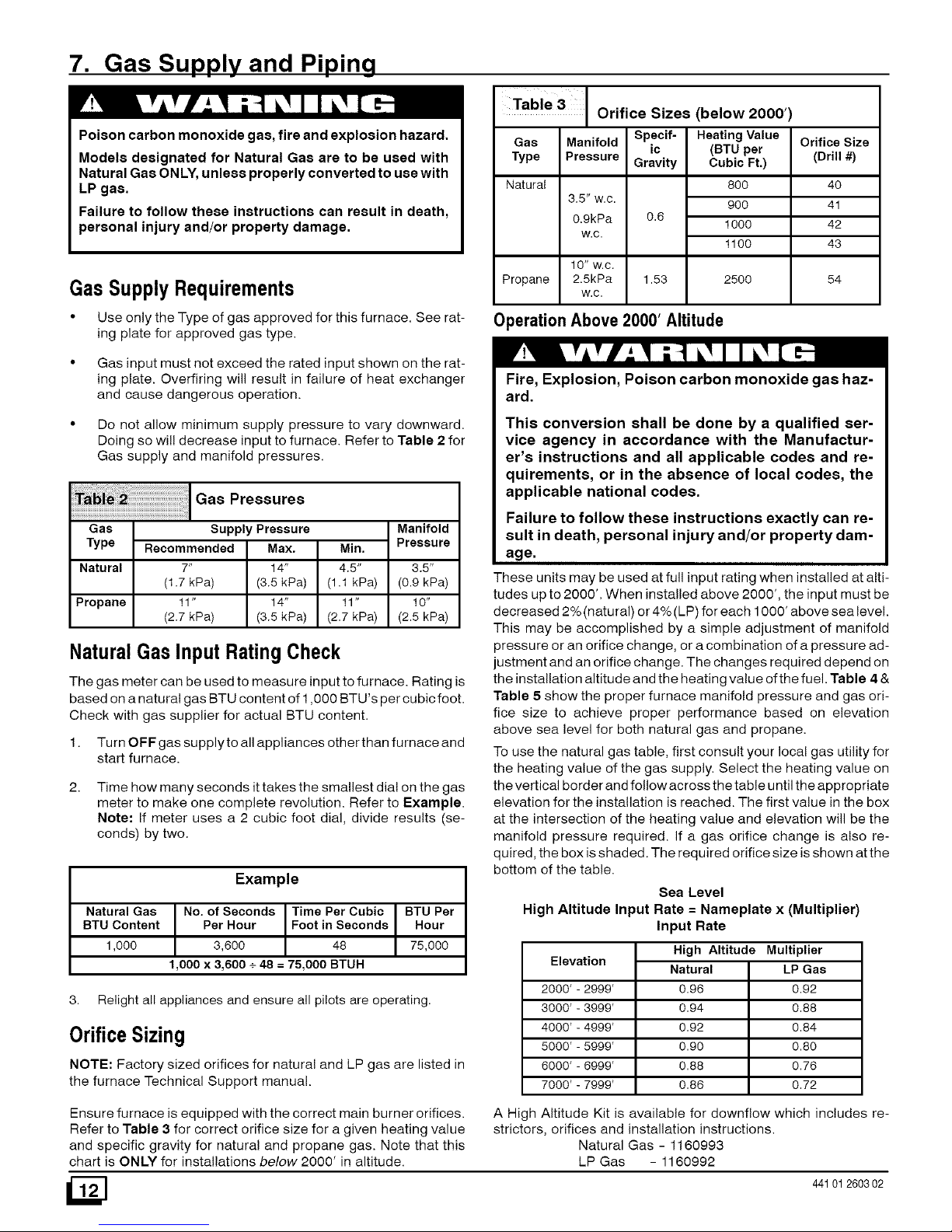
Table 3
Orifice Sizes (below 2000')
Gas Manifold Spacif- HeatingValue
ic (BTU par
Type Pressure Gravity Cubic Ft.)
Natural
Propane
GasSupplyRequirements
80O
3.5" w.c.
90O
0.9kPa 0.6
1000
w.c.
1100
10" w.c.
2.5kPa 1.53
w.c.
2500
Orifice Size
(Drill #)
4O
41
42
43
54
• Use only the Type of gas approved for this furnace. See rat-
ing plate for approved gas type.
OperationAbove 2000' Altitude
Gas input must not exceed the rated input shown on the rat-
ing plate. Overfiring will result in failure of heat exchanger
and cause dangerous operation.
Do not allow minimum supply pressure to vary downward.
Doing so will decrease input to furnace. Refer to Table 2 for
Gas supply and manifold pressures.
Pressures
Gas
Type
Natural
Manifold
Pressure
Supply Pressure
Recommended Max.
7" 14"
(1.7 kPa) (3.5 kPa)
11" 14"
(2.7 kPa) (3.5 kPa)
Min.
4.5" 3.5"
(1,1 kPa) (0.9 kPa)
Propane 11" 10"
(2.7 kPa) (2.5 kPa)
NaturalGas Input RatingCheck
The gas meter can be used to measure input to furnace. Rating is
based on a natural gas BTU content of 1,000 BTU's per cubic foot.
Check with gas supplier for actual BTU content.
1. Turn OFF gas supplyto all appliances otherthan furnace and
start furnace.
2.
Time how many seconds ittakes the smallest dial on the gas
meter to make one complete revolution. Refer to Example.
Note: If meter uses a 2 cubic foot dial, divide results (se-
conds) by two.
Example
Natural Gas No. of Seconds Time Per Cubic BTU Par
BTU Content Per Hour Foot in Seconds Hour
1,000 3,600 48 75,000
1,000 x 3,600 + 48 = 75,000 BTUH
3. Relight all appliances and ensure all pilots are operating.
OrificeSizing
NOTE: Factory sized orifices for natural and LP gas are listed in
the furnace Technical Support manual.
Fire, Explosion, Poison carbon monoxide gas haz-
ard.
This conversion shall be done by a qualified ser-
vice agency in accordance with the Manufactur-
er's instructions and all applicable codes and re-
quirements, or in the absence of local codes, the
applicable national codes.
Failure to follow these instructions exactly can re-
sult in death, personal injury and/or property dam-
age.
These units may be used at full input rating when installed at alti-
tudes up to 2000'. When installed above 2000', the input must be
decreased 2%(natural) or 4%(LP) for each 1000' above sea level.
This may be accomplished by a simple adjustment of manifold
pressure or an orifice change, or a combination of a pressure ad-
justment and an orifice change. The changes required depend on
the installation altitude and the heating value of the fuel. Table 4 &
Table 5 show the proper furnace manifold pressure and gas ori-
fice size to achieve proper performance based on elevation
above sea level for both natural gas and propane.
To use the natural gas table, first consult your local gas utility for
the heating value of the gas supply. Select the heating value on
the vertical border and follow across the table until the appropriate
elevation for the installation is reached. The first value in the box
at the intersection of the heating value and elevation will be the
manifold pressure required. If a gas orifice change is also re-
quired, the box is shaded. The required orifice size is shown atthe
bottom of the table.
Sea Level
High Altitude Input Rate -- Nameplate x (Multiplier)
Elevation
2000'-2999'
3000'-3999'
4000'-4999'
5000'-5999'
6000'-6999'
7000'-7999'
Input Rate
High Altitude Multiplier
Natural LP Gas
0.96 0.92
0.94 0.88
0.92 0.84
0.90 0.80
0.88 0.76
0.86 0.72
Ensure furnace is equipped with the correct main burner orifices.
Refer to Table 3 for correct orifice size for a given heating value
and specific gravity for natural and propane gas. Note that this
chart is ONLY for installations below 2000' in altitude.
/2N
A High Altitude Kit is available for downflow which includes re-
strictors, orifices and installation instructions.
Natural Gas - 1160993
LP Gas - 1160992
44101260302
Page 13
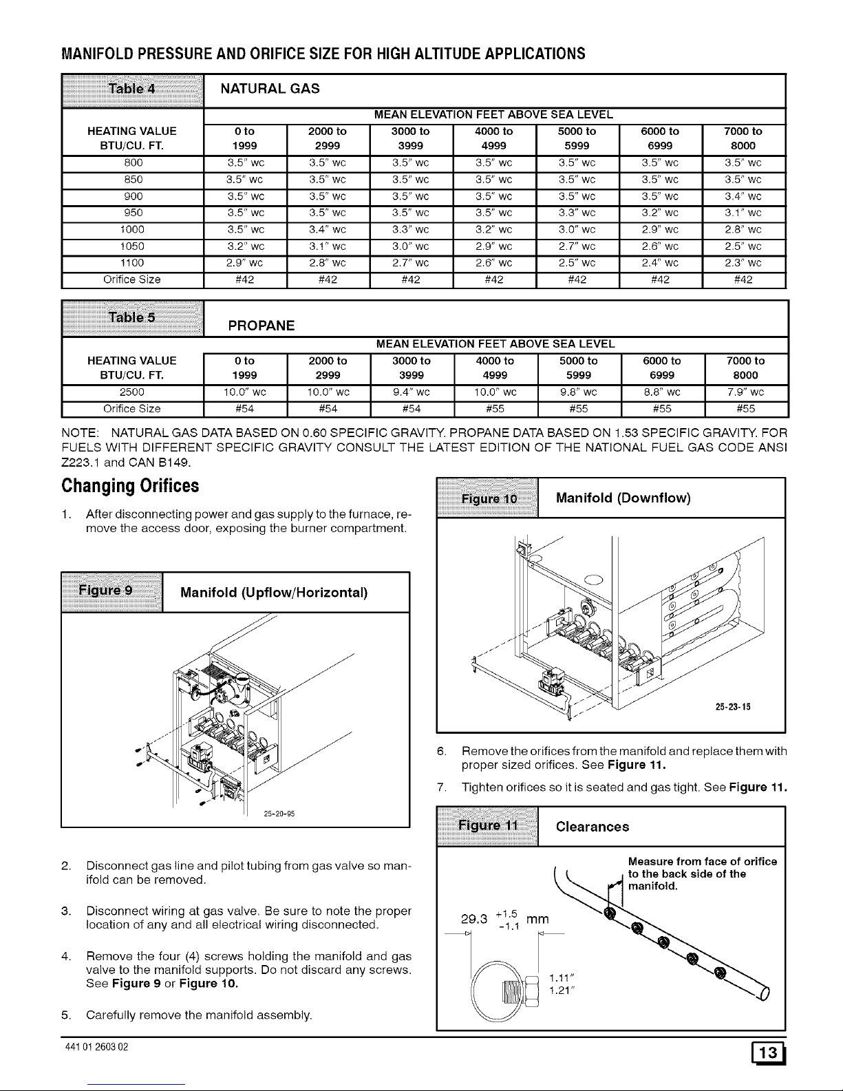
MANIFOLD PRESSUREAND ORIFICESIZE FOR HIGHALTITUDE APPLICATIONS
NATURAL GAS
MEAN ELEVATION FEET ABOVE SEA LEVEL
HEATING VALUE 0 to 2000 to 3000 to 4000 to 5000 to 6000 to 7000 to
BTU/CU. FT. 1999 2999 3999 4999 5999 6999 8000
800 3.5" wc 3.5" wc 3.5" wc 3.5" wc 3.5" wc 3.5" wc 3.5" wc
850 3.5" wc 3.5" wc 3.5" wc 3.5" wc 3.5" wc 3.5" wc 3.5" wc
900 3.5" wc 3.5" wc 3.5" wc 3.5" wc 3.5" wc 3.5" wc 3.4" wc
950 3.5" wc 3.5" wc 3.5" wc 3.5" wc 3.3" wc 3.2" wc 3.1" wc
1000 3.5" wc 3.4" wc 3.3" wc 3.2" wc 3.0" wc 2.9" wc 2.8" wc
1050 3.2" wc 3.1" wc 3.0" wc 2.9" wc 2.7" wc 2.6" wc 2.5" wc
1100 2.9" wc 2.8" wc 2.7" wc 2.6" wc 2.5" wc 2.4" wc 2.3" wc
Orifice Size #42 #42 #42 #42 #42 #42 #42
PROPANE
MEAN ELEVATION FEET ABOVE SEA LEVEL
HEATING VALUE 0 to 2000 to 3000 to 4000 to 5000 to 6000 to 7000 to
BTU/CU. FT. 1999 2999 3999 4999 5999 6999 8000
2500 10.0" wc 10.0" wc 9.4" wc 10.0" wc 9.8" wc 8.8" wc 7.9" wc
Orifice Size #54 #54 #54 #55 #55 #55 #55
NOTE: NATURAL GAS DATA BASED ON 0.60 SPECIFIC GRAVITY. PROPANE DATA BASED ON 1.53 SPECIFIC GRAVITY. FOR
FUELS WITH DIFFERENT SPECIFIC GRAVITY CONSULT THE LATEST EDITION OF THE NATIONAL FUEL GAS CODE ANSI
Z223.1 and CAN B149.
ChangingOrifices
1. After disconnecting power and gas supply to the furnace, re-
move the access door, exposing the burner compartment.
Manifold (Upflow/Horizontal)
jJ_
25-20-95
2.
3.
4.
Disconnect gas line and pilot tubing from gas valve so man-
ifold can be removed.
Disconnect wiring at gas valve. Be sure to note the proper
location of any and all electrical wiring disconnected.
Remove the four (4) screws holding the manifold and gas
valve to the manifold supports. Do not discard any screws.
See Figure 9 or Figure 10,
5. Carefully remove the manifold assembly.
Manifold (Downflow)
/
//
25-23-15
6. Remove the orifices from the manifold and replace them with
proper sized orifices. See Figure 11.
7. Tighten orifices so it is seated and gas tight. See Figure 11.
Clearances
Measure from face of orifice
( _ j to the back side of the
_anifold.
1.21"
44101 260302 [_
Page 14
8. Reassembleallpartsinreverseorderasremoved.Besureto
engagethemainburnerorificesintheproperopeninginthe
burners.
9. Afterreassembling,turngasonandcheckalljointsforgas
leaksusingasoapysolution.Allleaksmustberepairedim-
mediately.
GasPipingRequirements
1. Install gas piping in accordance with local codes, or in the ab-
sence of local codes, the applicable national codes.
2.
3.
4.
5.
6.
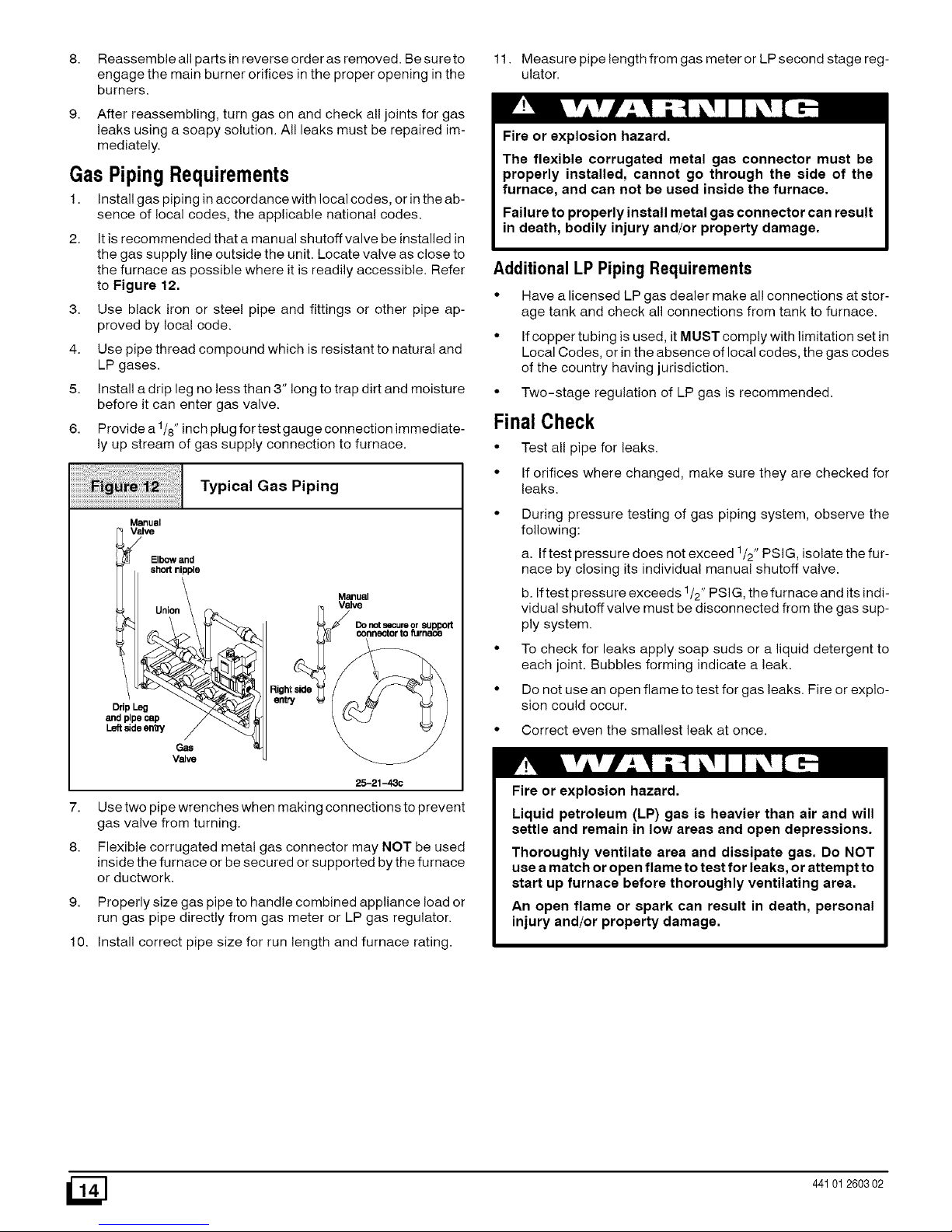
It is recommended that a manual shutoff valve be installed in
the gas supply line outside the unit. Locate valve as close to
the furnace as possible where it is readily accessible. Refer
to Figure 12.
Use black iron or steel pipe and fittings or other pipe ap-
proved by local code.
Use pipe thread compound which is resistant to natural and
LP gases.
Install a drip leg no less than 3" long to trap dirt and moisture
before it can enter gas valve.
Provide a 1/8" inch plug for test gauge connection immediate-
ly up stream of gas supply connection to furnace.
Typical Gas Piping
Manual
V_lve
Elbow and
short nipple
Union _
and pipe cap / _
L_deen_ / _._
Gas
Valve
Manuel
Valve
25-21-43c
7.
8.
Use two pipe wrenches when making connections to prevent
gas valve from turning.
Flexible corrugated metal gas connector may NOT be used
inside the furnace or be secured or supported by the furnace
or ductwork.
9. Properly size gas pipe to handle combined appliance load or
run gas pipe directly from gas meter or LP gas regulator.
10. Install correct pipe size for run length and furnace rating.
11. Measure pipe length from gas meter or LP second stage reg-
ulator.
Fire or explosion hazard.
The flexible corrugated metal gas connector must be
properly installed, cannot go through the side of the
furnace, and can not be used inside the furnace.
Failure to properly install metal gas connector can result
in death, bodily injury and/or property damage.
Additional LP PipingRequirements
• Have a licensed LP gas dealer make all connections at stor-
age tank and check all connections from tank to furnace.
• If copper tubing is used, it MUST comply with limitation set in
Local Codes, or in the absence of local codes, the gas codes
of the country having jurisdiction.
• Two-stage regulation of LP gas is recommended.
FinalCheck
• Test all pipe for leaks.
• If orifices where changed, make sure they are checked for
leaks.
During pressure testing of gas piping system, observe the
following:
a. If test pressure does not exceed 1/2" PSIG, isolate the fur-
nace by closing its individual manual shutoff valve.
b. If test pressure exceeds 1/2" PSIG, the furnace and its indi-
vidual shutoff valve must be disconnected from the gas sup-
ply system.
To check for leaks apply soap suds or a liquid detergent to
each joint. Bubbles forming indicate a leak.
Do not use an open flame to test for gas leaks. Fire or explo-
sion could occur.
• Correct even the smallest leak at once.
Fire or explosion hazard.
Liquid petroleum (LP) gas is heavier than air and will
settle and remain in low areas and open depressions.
Thoroughly ventilate area and dissipate gas. Do NOT
use a match or open flame to test for leaks, or attempt to
start up furnace before thoroughly ventilating area.
An open flame or spark can result in death, personal
injury and/or property damage.
_] 441012603 02
Page 15

8. Electrical Wiring
Electrical shock hazard.
Turn OFF electrical power at fuse box or service panel
before making any electrical connections and ensure a
proper ground connection is made before connecting
line voltage.
Failure to do so can result in death, personal injury
and/or property damage.
PowerSupplyWiring
The furnace MUST be electrically wired and grounded in accor-
dance with local codes, or in the absence of local codes, the appli-
cable national codes.
Field wiring connections must be made inside the furnace con-
nection box. A suitable strain relief should be used at the point the
wires exit the furnace casing.
Copper conductors shall be used. Line voltage wires should be
sized for the input amps stated on the rating plate. Furnace must
be connected to its own separate circuit.
Thermostat
Thermostat location has an important effect on the operation of
the unit. Follow instructions included with thermostat for correct
mounting and wiring.
Low voltage connections to furnace must be made on terminal
board to fan control. (See Figure 13 or Figure 14)
If cooling is used, the Y from the thermostat must be connected to
the control board Y to energize cooling blower speed.*
Set thermostat heat anticipator in accordance with the Technical
Support Manual.
OptionalEquipment
All wiring from furnace to optional equipment MUST conform to
local codes or, in the absence of local codes, the applicable na-
tional codes. Install wiring in accordance with manufacturer's
instructions.
Humidifier/ElectronicAir Cleaner
The furnace is wired for humidifier and/or electronic air cleaner
connection.
CAUTION
Do NOT exceed 115V/0,8 amp, maximum current load
for both the EAC terminal and the HUM terminal com-
bined.
NOTE: The humidifier will be powered when the furnace is fired
and the circulating air blower comes on. The electronic air cleaner
will be powered anytime the thermostat calls for air movement.
However, the electronic air cleaner is NOT energized during con-
tinuous fan operation controlled by the electronic fan control.
Electrical Connections
(Upflow/Horizontal)
115V, 60Hz
NEUT.
Connection Box
Ground
Thermostat
i i
I i ! _ I
--q I I I
Low Voltage
Termina_Board
25-22-30
115V, 60Hz
NEUT.
Electrical Connections
(Downflow)
Ground
LowVoltage
TerminalBoard
25-21-05b
Control CenterFuse
The 24V circuit contains a 5-amp, automotive-type fuse located
on control center. (See Figure 15) Any electrical shorts of 24V
wiring during installation, service, or maintenance may cause
fuse to blow. If fuse replacement is required, use only a fuse of
identical size (5 amp.)
44101 260302 [_
Page 16

Fan Timer Connections
Fuse
25-22-68
9. Ductwork and Filter (Upflow/Horizontal)
Poison carbon monoxide gas hazard.
Do NOT draw return air from inside a closet or utility
room where furnace is located. Return air duct MUST
be sealed to furnace casing.
Failure to properly seal duct can result in death and/or
personal injury.
When the furnace is located in an area near or adjacent to the liv-
ing area, the system should be carefully designed with returns to
minimize noise transmission through the return air grille. Any
blower moving a high volume of air will produce audible noise
which could be objectionable when the unit is located very close
to a living area. It is often advisable to route the return air ducts
under the floor or through the attic.
• Refer to furnace Technical Support Manual (Blower Data)
for air flow information.
DuctConnections
This furnace may be installed in only a bottom or side return ap-
plication. Return air through the back of the unit is NOT allowed.
Side connections can be made by cutting out the embossed area
shown in Figure 16,
Cutting Side Return Air Opening
Starting
Hole
• Size ductwork to handle air flow for heating and air condition-
ing if used.
DuctInstallationRequirements
• When furnace supply ducts carry air outside furnace area,
seal return air duct to furnace casing and terminate duct out-
side furnace space.
• When a refrigeration coil is used in conjunction with this unit,
it must be installed on the discharge side of the unit to avoid
condensation on the heat exchanger.
If separate evaporator and blower unit is used, install good
sealing dampers for air flow control. Chilled air going through
the furnace could cause condensation and shorten furnace
life. Dampers (purchased locally) can be either automatic or
manual. Manually operated dampers MUST be equipped
with a means to prevent furnace or air conditioning operation
unless damper is in the full heat or coo! position.
Bottom returns can be made by removing the knockout panel in
the furnace base. Do NOT remove knock-out except for a bottom
return.
Duct Design
Design and install air distribution system to comply with Air Condi-
tioning Contractors of America manuals or other approved meth-
ods that conform to local codes and good trade practices.
Poison carbon monoxide gas hazard.
Cool air passing over heat exchanger can cause
condensate to form resulting in heat exchanger failure.
This could result in personal injury and/or death.
Installation of locking-type dampers are recommended in all
branches, or in individual ducts to balance system's air flow.
If air return grille is located close to the fan inlet, install at least
one, 90 ° air turn between fan and inlet grille to reduce noise.
441012603 02
Page 17

Ductwork installed in attic, or exposed to outside tempera-
tures requires a minimum of 2" of insulation with outdoor type
vapor barrier.
Ductwork installed in an indoor unconditioned space re-
quires a minimum of 1" of insulation with indoor type vapor
barrier.
Filters
A filter MUST be used:
Filters are not supplied with these furnaces, but can be purchased
from your dealer.
Use either filter type:
• Washable, high velocity filters are based on a maximum air
flow rating of 600 FPM.
• Disposable, Iowvelocity filters are based on a maximum air
flow of 300 FPM when used with filter grille.
• The furnaces, with 1600 or less CFM rating use a 16" x 25"
high velocity filter. On these models the filter may be
mounted internally for bottom return using factory kit or ex-
ternally for side return.
• The furnaces with greater than 1600 CFM requires that
both !eft and right side returns are used in side return ap-
plications. Two 16" x 25" high velocity filters and racks are
provided with furnace. Filter racks must be mounted exter-
nally. !f return air must be on one side only. an optional 20" x
25" filter standoff rack kits can be used. (See Figure 17)
For bottom return, an optional 20" x 25" filter rack kit can be
mounted internally.
10. Ductwork and Filter (Downflow)
Fire or explosion hazard.
Use sub-base for downflow installation on combustible
floors.
Failure to use sub-base on combustible floors can result
in death, bodily injury and/or property damage.
Sub-Bases for CombustibleFloors - Furnace Only
The Subbase for Combustible Floors MUST be used when a
downflow furnace is set on combustible material even when the
furnace is installed on a col! box (cased col!).
NOTE: The 20 x 25" standoff filter rack gives more filter area but
does not provide more air. To achieve 2000 CFM a bottom return
or 2 side returns are still needed.
NOTE: Disposable, low velocity filters may be replaced with
washable, high velocity filter providing they meet the minimum
size areas. Washable, high velocity filters can be replaced ONLY
with same type and size.
Figure 17
1
Optional Duct Standoff
20 x 25 Optional
Filter Rack
NOTE: Supply opening is 37/8" from the rear of the furnace.
Therefore maintain a 37/8" clearance from a wall behind the fur-
nace (where applicable).
Cut the opening in the floor according to Table 6. The hole in
the floor must be cut to the dimensions listed in Table 6 since
the base is equipped with locating tabs that center the base
over the opening.
The opening in the base is 1t/4" shorter and 1t/8" narrower than
the minimum required size of the opening in the floor. This is done
to maintain a 1" clearance between the floor and the plenum.
2. Fabricate the plenum to the dimensions given in Table 6.
Note that the dimensions given are outside dimensions.
Sub-bases for Combustible Floors Dimensions
H _
15tl/16
195/16
22t5/16
15tl/16
195/I6
22t5/16
sub-base for Com-
bustible Floors
Part Number
(Furnace Only)
NAHHOOlSB
NAHHOO2SB
NAHHOO3SB
sub-base for
Cased Coil
NAHHOO4SB
NAHHOO5SB
NAHHOOSSB
* Outside Dimension
sub-base for Combustible
Floor Dimensions
J* K**
283/4 149/16
283/4 183/16
283/4 2113/16
209/16 149/I6
209/16 183/I6
209/16 2113/16
Opening In Floor
L M N
16 161/4 145/8
16 161/4 181/4
16 161/4 217/8
16 161/4 145/8
16 161/4 181/4
16 161/4 217/8
Opening In
Base For Plenum
Typical Plenum
Dimensions
15
15
15
P R
15 13t/2
15 17t/8
15 193/4
15 13t/2
15 17t/8
15 193/4
15
15
15
131/2
171/8
193/4
131/2
171/8
193/4
** Base Spacer Side To Side
44101 260302
Page 18

3.
4.
Set the base overthe opening in the floor, centering the open-
ing in the base over the opening in the floor. Fasten the base
to the floor with screws or nails. See Figure 18 and
Figure 20.
Drop the plenum through the opening in the base. The flange
of the plenum should rest on top of the combustible floor
base.
Exploded View of Sub-Base
Figure 18 for Furnace ONLY
Sub-base for Combustible Floors- Downflow Coil
Box
The Subbase for Combustible Floors MUST be used when a
downflow furnace, used with a downflow coil box, is set on
combustible flooring.
NOTE: Supply opening is 37/8" from the rear of the furnace.
Therefore maintain a 37/8" clearance from wall (where applica-
ble).
Cut the opening in the floor according to Table 6. The hole in
the floor must be cut to the dimensions listed in Table 6 since
the base is equipped with locating tabs that center the base
over the opening.
The opening in the base is 11/4" shorter and 1 1/8" narrower than
the recommended size of the opening in the floor. This is done to
provide a 1" clearance between the floor and the plenum.
2.
3.
4.
Fabricate the plenum to the dimensions given in Table 6.
Note that the dimensions given are outside dimensions.
Set the base over the opening in the floor, centering the open-
ing in the base over the opening in the floor. Fasten the base
to the floor with screws or nails. See Figure 19 and
Figure 20.
Drop the plenum through the opening in the base. The flange
of the plenum should rest on top of the combustible floor
base.
Figure 19 Exploded View of Base for
Downflow Cased Coil
Setting the Base
Subbase
Insulation
25-21-46b
Wood Floor
25 20 46A
This subbase for combustible floors has been designed so that
the height of the sub-base raises the downflow coil off the floor to
allow easy installation of the condensate drain. See Figure 21.
Figure 21 Condensate Line Raised by Base
Filters:
25-20-52
The filter may be installed in the return air plenum above the fur-
nace. A filter rack is supplied with each furnace. See Figure 22 or
Figure 23.
NOTE: The return air plenum MUST extend a sufficient height
above dimensions "A" (Figure 23) to provide for the attachment
of a return air duct or grille above the filters.
1. Insert end of filter rack with 3/4" (19mm) flange into slot in the
back of the unit, See Figure 22.
_] 441012603 02
Page 19

2.
With filter rack pushed back, insert front end with 1/4" flange
into position and push into front slot. with filter rack pushed as
far forward as it will go, bend 1/4" flange and 3/4" flange up
90°. See Figure 22.
NOTE: Plenum must be fitted as close to the return air flange of
the unit as possible to eliminate any air bypassing the filters.
NOTE: If filters are installed in the plenum with the filter rack pro-
vided use two 16" x 18" high velocity filters. Otherwise consult fil-
ter section of the "User's Information Manual" for proper size.
Figure 22 Filter Rack Installation
25-21-05c
3. Filters can only be installed through the right hand side of the
unit blower opening. Slide filter into unit until it is in position to
be pushed up and over into place on the left hand side of unit.
See Figure 23.
4. Slide remaining filter into unit and up into place on left hand
side of unit. See Figure 23.
Figure 23 Filter Installation
25-21-05d
If there is insufficient plenum height for this type of installation, fil-
ters may be installed in any accessible location in the return air
system. In such a case, the filters should be of adequate size and
style as originally supplied with the furnace.
Filter Removal
1. Remove compartment door.
2. Reach up above right side of blower and lift dirty filters out of
rack at top of furnace.
3. Straighten up filters and pull straight down at side of blower.
Pull out through right door opening.
4. Vacuum clean or wash with warm water and dry thoroughly
before replacing.
11. Checks and Adjustments
Startup
NOTE: Refer to startup procedures in the Users Information
Manual.
CAUTION
If any sparks, odors or unusual noises occur, immedi-
ately shut OFF power to furnace. Check for wiring er-
rors or obstruction to blower.
Fire or explosion hazard.
Turn OFF gas at shut off before
manometer.
connecting
Failure to turn OFF gas at shut off before connecting
manometer can result in death and/or personal injury.
GasSupplyPressure
Gas supply pressure should be within minimum and maximum
values listed on rating plate. Pressures are usually set by gas sup-
pliers.
(See L.R Kit instruction manual for furnaces converted to L.R
gas)
ManifoldGas PressureAdjustment
NOTE: Make adjustment to manifold pressure with burners oper-
ating.
1. With gas OFF, Connect manometer to gas valve or maniflod
tap. Use manometer with a 0 to min. 12" water column range.
2. Turn gas ON and remove adjustment screw cover on gas
valve. Turn counterclockwise to decrease pressure and
clockwise to increase.
NOTE: Adjustment screw cover MUST be placed on gas valve
before reading manifold pressure and operating furnace.
3. For altitudes up to 2000', set pressure to value shown in
Table 2. For altitudes between 2000' to 8000', see Section
7. "Gas Supply and Piping" for correct pressure value.
44101 260302 [_
Page 20

AdjustPilot Burner
The furnace has a pilot flame to light the main burner. The flame
should surround 3/8" to 1/2" of the flame rod. See Figure 24. To
adjust, remove cap from pilot adjusting screw on gas valve. Turn
screw counterclockwise to increase or clockwise to decrease
flame as required. Replace cap after adjusting screw.
iiiiiiiiiiiiiiiiJ!;iiiiiiiiiil¸;i ;;;;;;;;;;!!ii ¸ ;;;;;
Proper flame
adjustment
Pilot Burner
3/8to 1/2"
Igniter-sensor
I 10-12-12c
ChangingBlowerSpeed
Electrical shock hazard.
Turn OFF power to furnace before changing speed taps.
Failure to do so can result in death, personal injury
and/or property damage.
NOTE: The speed taps that the manufacture sets from the factory
for this product are based on a nominal 400 CFM per ton cooling
and the basic mid range on the temperature rise for heating.
Since the manufacturer cannot establish the static pressure
that will be applied to the unit, it is the responsibility of the
installer deal er/contractor to select the proper speed taps for
the application when the unit is installed.
If it is necessary to change speeds, refer to steps below.
1. Refer to Furnace Wiring Diagram for location of the heating
and cooling speed taps located on the electronic fan control
as well as location of unused blower motor speed leads. Use
the chart (Table 7) to determine the blower motor speed set-
tings.
Main BurnerFlameCheck
Allow the furnace to run approximately 10 minutes then inspect
the main burner and pilot flames. See Figure 25.
Check for the fol!owing (Figure 25):
• Stable and blue flames. Dust may cause orange tips or
wisps of yellow, but flames MUST NOT have solid, yellow
tips.
• Flames extending directly from burner into heat exchanger.
• Flames do NOT touch sides of heat exchanger
If any problems with main burner flames are noted, it may be nec-
essary to adjust gas pressures, or check for drafts.
Main Burner
10-10-78
TemperatureRiseCheck
The blower speed MUST be set to give the correct air temperature
rise through the furnace as marked on the rating plate. Tempera-
ture rise is the difference between supply and return air tempera-
tures.
IN
Blower Speed Chart
Wire Color
Black
Orange*
Blue
Red
Motor Speed
High
Med-High
Medium
low
* Med-High speed may not be provided on all models.
Change the heat or cool blower motor speed by removing the
motor lead from the "Heat" or "Cool" terminal and replace it
with the desired motor speed lead from the "Unused Motor
Lead" location. Connect the wire previously removed from
the "Heat" or "Cool" terminal to the vacated "Unused Motor
Lead" terminal.
Ifthe same speed must be used for both heating and cooling,
remove the undesired motor speed lead from the "Heat" or
"Cooi"terminal and connect that lead to the open terminal at
"Unused Motor Lead" location ortape off. Attach a jumper
between the "Heat" and "Cool" terminals and the remaining
motor speed lead.
Note: When using the same speed on motors with (4) speed
leads, it will be necessary to tape off the terminal of the motor
speed lead removed from the "Heat" or "Cool" terminal with
electrical tape since an open terminal wi!! not be available at
the "Unused Motor Lead" location.
ContinuousFanOperation
A terminal is provided on the electronic fan control located in the
circulating blower compartment for operation of the continuous
fan option. This connection is intended for the low speed motor
tap, and has a lower contact rating (8 amps) than the heat and
cool taps. When the low speed blower lead is connected to this
terminal, this will provide low speed blower operation whenever
the other two speeds (Heat or Cool) are not energized.
Thoroughly check the system after modification to ensure the
proper operation of the circulating air blower in all modes of opera-
tion.
441012603 02
Page 21

Separatespeed selectionsfor Heat, Cool,and
Continuous Fan
Connect low speed lead from circulating motor to the "Cont" ter-
minal at the electronic fan control. The appropriate motor leads
should already be connected to the "Heat" and "Cool" terminals.
Heating and Continuous Blower Speed the Same
If it is necessary to operate the heating speed and continuous
blower speed using the same blower speed, connect a jumper be-
tween the "Neat" and "Cont" terminals on the electronic fan con-
trol.
Note: There should be only ONE motor lead going to the "Heat"
and "Cont" terminals.
12. Furnace Maintenance
CAUTION
It is recommended that the furnace be inspected and
serviced on an annual basis (before the heating sea-
son) by a qualified service technician.
See "User's Information Manual".
44101 260302 [_
Page 22

Save This Manual For Future Reference
Models
NTC6050FBG1
NTC6075FBG1
NTC6075HFG1
NTC6100GFG1
NTC6100KFG1
NTC6100KJG1
NTC6125KJG1
NTC6150KJG1
NTN6050FBG1
NTN6075FBG1
NTN6075HFG1
NTN6100KFG1
NTN6100KJG1
NTN6125KJG1
NDN6050FBG1
NDN6075FBG1
NDN6075HFG1
NDN6100GFG1
NDN6100KFG1
NDN6125KJG1
GNE050B12G1
GNE075B12G1
GNE075F16G1
GNE100F14G1
GNE100F20G1
GNE100J20G1
GNE125J20G1
GNE150J20G1
NNE050B12G1
NNE075B12G1
NNE075F16G1
NNE100F20G1
NNE100J20G1
NNE125J20G1
GDE050B12G1
GDE075B12G1
GDE075F16G1
GDE100F14G1
GDE100F20G1
GDE125J20G1
Models
NTN3050FBG1
NTN3075FBG1
NTN3075HFG1
NTN3100KFG1
NTN3100KJG1
NTN3100LJG1
NTN3125KJG1
NTN3125LJG1
NTG3050FBG1
NTG3075FBG1
NTG3075HFG1
NTG3100GFG1
NTG3100KFG1
NTG3100LJG1
NTG3125KJG1
NTG3125LJG1
NDN3050FBG1
NDN3075FBG1
NDN3075HFG1
NDN3100GFG1
NDN3100KFG1
NDN3125KJG1
NBF050B12G1
NBF075B12G1
NBF075F16G1
NBF100F20G1
NBF100J20G1
NBF100J22G1
NBF125J20G1
NBF125J22G1
FBF050B12G1
FBF075B12G1
FBF075F16G1
FBF100F14G1
FBF100F20G1
FBF100J22G1
FBF125J20G1
FBF125J22G1
NDF050B12G1
NDF075B12G1
NDF075F16G1
NDF100F14G1
NDF100F20G1
NDF125J20G1
Manufactured by:
International Comfort Products Corporation (USA)
Lewisburg, TN USA 37091
_] 44101 260302
Page 23

ManufacturersNumber(Mfr No-See RatingPlate)
ALL Models
Specifications
NTN305OFB/ NTN3075FB/ NTN3075HF/ NTN31OOKF/ NTN31OOKJ/ NTN31OOLJ/ NTN3125KJ/ NTN3125LJ/
NBFO5OB12 NBFO75B12 NBFO75F16 NBFIOOF20 NBFIOOJ20 NBFIOOJ22 NBF125J20 NBF125J22
NTG305OFB NTG3075FB NTG3075HF NTG31OOKF NTG31OOLJ/ NTG3125KJ/ NTG3125LJ/
/FBFO5OB12 /FBFO75B12 /FBFO75F16 /FBFIOOF20 FBFIOOJ22 FBF125J20 FBF125J22
General
Input(Btuh) 50,000 75,000 75,000 100,000 100,000 1O0,OO0 125,000 125,000
Output(Btuh) 40,000 59,000 59,000 79,000 79,000 79,000 99,000 99,000
Temp.Rise (F) 35-65 35-65 25-55 35-65 35-65 40-70 40-70 40-70
Electrical(Votts/Hz!FLA) 115/60/5.3 115/60/5.3 115/60/12.0 115/60/12.0 115/60/12.0 115/60/12.0 115/60/12.0 115/60/12.0
GasType Nat LP Nat LP Nat LP Nat LP Nat LP Nat LP Nat LP Nat LP
Transformer Size (VA) 40 40 40 40 40 40 40 40 40 40 40 40 40 40 40 40
T'statHeat Anticipator .30 .30 .30 .30 .30 .30 .30 .30 .30 .30 .30 .30 .30 .30 .30 .30
Gas& Ignition
Std.MainOrifices(No/Size) 2/#42 2/#54 3/#42 3/#54 3/#42 3/#54 4/#42 4/#54 4/#42 4/#54 4/#42 4/#54 5/#42 5/#54 5/#42 5/#54
GasValve HoneywellVR 8204 8204 8204 8204 8204 8204 8204 8204 8204 8204 8204 8204 8204 8204 8204 8204
RegulationType SNAP SNAP SNAP SNAP SNAP SNAP SNAP SNAP SNAP SNAP SNAP SNAP SNAP SNAP SNAP SNAP
ManifoldPress.(Inch'sWC) 3.5 10.0 3.5 10.0 3.5 10.0 3.5 10.0 3.5 10.0 3.5 10.0 3.5 10.0 3.5 10.0
PilotOrificeSize .018 .011 .018 .011 .018 .011 .018 .011 .018 .011 .018 .011 .018 .011 .018 .011
IgnitionType/Series HW S8600 HW $8600 HW$8600 HW$8600 HW $8600 HW$8600 HW$8600 HW $8600
Lock-Out Time NA NA NA NA NA NA NA NA
Combustion
FlueOutlet Size (Inches) 3 3 3 3 3 3 3 3
Std.OutletTemp(F) <480 <480 <480 <480 <480 <480 <480 <480
Limits &Controls
ThermalSensor ('F) 300 300 300 300 300 300 300 300
LimitControlSetting(F) See PartsList SeeParts List See PartsList See PartsList See PartsList SeeParts List See PartsList See PartsList
Auxiliary Umit (F) 130 130 130 130 130 130 130 130
Std.PressureSw. (PartNo) 1010898 1010898 1010898 1010898 1010898 1010898 1010898 1010898
Press(Close) -0.81 -0.81 -0.81 -0.81 -0.81 -0.81 -0.81 -0.81
Press(Open) -0.65 -0.65 -0.65 -0.65 -0.65 -0.65 -0.65 -0.65
FanControl(Type) HWST9120 HWST9120 HW ST9120 HWST9120 HWST9120 HW ST9120 HWST9120 HW ST9120
FanControt On 30/60 30/60 30/60 30/60 30/60 30/60 30/60 30/60
(Timed-secs) Off 60,100,140,180 60,100,140,180 60,100,140,180 60,100,140,180 60,100,140,180 60,100,140,180 60,100,140,180 60,100,140,180
Blower Data
Type&Size 10-8 10-8 10-10 10-10 11-10 11-10 11-10 11-10
MotorAmps/Rpm 6.5/1050 6.5/1050 10.3/110O 11.9/900 11.9/900 11.9/900 11.9/900 11.9/900
MotorType/H.p. PSC/1/3 PSC/1/3 PSC/1/2 PSC/3/4 PSC/3/4 PSC/3/4 PSC/3/4 PSC/3/4
Cap.MfdiVolts 5/370 5/370 10/370 10/370 10/370 10/370 10/370 10/370
FilterType Washable Washable Washable Washable Washable Washable Washable Washable
FilterSize (") 14x25x1 14x25x1 16x25x1 16x25x1 16x25x1 16x25x1 16x25x1(2) 16x25x1
Min.CootCap. (Tons) 1.5 1.5 3 3 3 3 3 3
Max.0oot OaF (Tons) 3 3 4 5 5 5 5 5
GasConversionKits
Natto LP NAHFOO2LPor NAHLO02LP,*1160991
LPto Nat NAHF002NG,*1009510*
LPHighAltitude *1160992
*Mustbe orderedfromServiceParts
44101260302 THIS DATA IS SUBJECT TO CHANGE WITHOUT NOTICE [_]
Page 24

ManufacturersNumber(Mfr No-See RatingPlate)
ALL Models
Specifications
NDN305OFB/ NDN3075FB/ NDN3075HF/ NDN31OOGF/ NDN31OOKF/ NDN3125KJ/
NDFO5OB12 NDFO75B12 NDFO75F16 NDFIOOF14 NDFIOOF20 NDF125J20
General
Input(Btuh) 50,000 75,000 75,000 100,000 100,000 125,000
Output(Btuh) 40,000 61,000 61,000 81,000 81,000 102,000
Temp.Rise (F) 30-60 40-70 40-70 40-70 40-70 45-75
Electrical(Volts/liz!FLA) 115/60/5.3 115/60/5.3 115/60/12.0 115/60/7.5 115/60/12.0 115/60/12.0
GasType Nat LP Nat LP Nat LP Nat LP Nat LP Nat LP
Transformer Size (VA) 40 40 40 40 40 40 40 40 40 40 40 40
T'statHeat Anticipator .30 .30 .30 .30 .30 .30 .30 .30 .30 .30 .30 .30
Gas& Ignition
Std.MainOrifices(No/Size) 2/#42 2/#54 3/#42 3/#54 3/#42 3/#54 4/#42 4/#54 4/#42 4/#54 5/#42 5/#54
GasValve Honeywell SV9501 SV9501 SV9501 SV9501 SV9501 SV9501 SV9501 SV9501 SV9501 SV9501 SV9501 SV9501
RegulationType SNAP SNAP SNAP SNAP SNAP SNAP SNAP SNAP SNAP SNAP SNAP SNAP
ManifoldPress.(Inch'sWC) 3.5 10.0 3.5 10.0 3.5 10.0 3.5 10.0 3.5 10.0 3.5 10.0
PilotOrificeSize .018 .011 .018 .011 .018 .011 .018 .011 .018 .011 .018 .011
IgnitionType/Series HWHSP HWHSP HW HSP liW liSP liW HSP HW HSP
Lock-Out Time NA NA NA NA NA NA
Limits &Controls
ThermalSensor('F) 300 300 300 300 300 300
LimitControlSetting(F) See Parts Ust SeePartsList See Parts List See PartsList See PartsList SeeParts List
Auxiliary Limit (F) 110 110 110 110 110 110
Std.PressureSw. (PartNo) 1010898 1010898 1010898 1010898 1010898 1010898
Press(Close) -0.75 -0.75 -0.75 -0.75 -0.75 -0.75
Press(Open) -0.65 -0.65 -0.65 -0.65 -0.65 -0.65
FanControl(Type) HWST9120 HW ST9120 HWST9120 liW ST9120 liW ST9120 HW ST9120
FanControtOn 30/60 30/60 30/60 30/60 30/60 30/60
(Timed-secs) Off 60,100,140,180 60,100,140,180 60,100,140,180 60,100,140,180 60,100,140,180 60,100,140,180
Combustion
FlueOutlet Size (Inches) 3 3 3 3 3 3
Std.OutletTemp(F) <480 <480 <480 <480 <480 <480
Blower Data
Type&Size 10-8 10-8 11-10 11-10 11-10 11-10
MotorAmps/Rpm 6.5/1050 6.5/1050 10.3/1100 8/1050 10.3/1100 11.9/900
MotorType!H.p. PSC/1/3 PSC/1/3 PSC/1/3 PSC/1/2 PSC/1/2 PSC/3/4
Cap.MfdNolts 5/370 5/370 5/370 5/370 5/370 5/370
FilterType Washable Washable Washable Washable Washable Washable
FilterSize (') 16xl8xl (2) 16xl 8xl (2) 16xl8xl (2) 16xl8xl (2) 16xl 8xl (2) 16xl8xl (2)
Min.CootCap. (Tons) 1.5 1.5 3 2 3 3
Max.CoolCap.(Tons) 3 3 4 3.5 5 5
GasConversionKits
Natto LP NAHF002LPor NAHL002LP,*1160991
LPto Nat NAHF002NG,'1009510'
LPHighAltitude "1160992
*Mustbe orderedfromServiceParts
_] THIS DATA IS SUBJECT TO CHANGE WITHOUT NOTICE 44101260302
Page 25

ManufacturersNumber(Mfr No-See RatingPlate)
ALL Models
Specifications
NTC605OFB/ NTC6075FB/ NTC6075HF/ NTC6100GF/ NTC6100KF/ NTC6100KJ/ NTC6125KJ/
GNEO50B12 GNEO75B12 GNEO75F16 GNE100F14 GNEIOOF20 GNEIOOJ20 GNE125J20
NTN605OFB/ NTN6075FB/ NTN6075HF/ NTN6100KF/ NTN6100KJ/ NTN6125KJ/
NNEO50B12 NNEO75B12 NNEO75F16 NNEIOOF20 NNEIOOJ20 NNE125J20
General
Input(Btuh) 50,000 75,000 75,000 100,000 100,000 100,000 125,000
Output(Btuh) 40,000 59,000 59,000 79,000 79,000 79,000 99,000
Temp.Rise (F) 35-65 35-65 25-55 45-75 35-65 35-65 40-70
Electrical(Votts/Hz!FLA) 115/60/5.3 115/60/5.3 115/60/12.0 115/60/7.5 115/60/12.0 115/60/12.0 115/60/12.0
GasType Nat I LP NatI,P Nat Nat NatI,P NatI,P Nat I 'P
Transformer Size (VA) 40 40 40 40 40 40 40
T'statHeat Anticipator .30 .30 .30 .30 .30 .30 .30
Gas& Ignition
GasType Nat LP Nat LP Nat LP Nat LP Nat LP Nat LP Nat LP
Std.MainOrifices(No/Size) 2/#42 2/#54 3/#42 3/#54 3/#42 3/#54 4/#42 4/#54 4/#42 4/#54 4/#42 4/#54 5/#42 5/#54
GasValve HoneywellSV 9501 9501 9501 9501 9501 9501 9501 9501 9501 9501 9501 9501 9501 9501
RegulationType SNAP SNAP SNAP SNAP SNAP SNAP SNAP SNAP SNAP SNAP SNAP SNAP SNAP SNAP
ManifoldPress.(Inch'sWC) 3.5 10.0 3.5 10.0 3.5 10.0 3.5 10.0 3.5 10.0 3.5 10.0 3.5 10.0
PilotOrificeSize .018 .011 .018 .011 .018 .011 .018 .011 .018 .011 .018 .011 .018 .011
IgnitionType/SeriesHoneywell HSP HSP HSP HSP HSP HSP HSP
Lock-Out Time NA NA NA NA NA NA NA
Combustion
FlueOutlet Size (Inches) 3 3 3 3 3 3 3
Std.OutletTemp(F) <480 <480 <480 <480 <480 <480 <480
Limits&Controls
ThermalSensor (F) 300 300 300 300 300 300 300
LimitControlSetting(F) See PartsList See PartsList See PartsList See PartsList SeeParts List SeeParts List See PartsList
Auxiliary Umit ('F) 130 130 130 130 130 130 130
Std.PressureSw. (PartNo) 1010897 1010897 1010897 1010896 1010896 1010896 1010898
Press(Close) -0.50 -0.50 -0.50 -0.60 -0.60 -0.60 -0.75
Press(Open) -0.40 -0.40 -0.40 -0.50 -0.50 -0.50 -0.65
FanControl(Type) HW ST9120 HW ST9120 HW ST9120 HW ST9120
FanControl On 30/60 30/60 30/60 30/60
(Timed-secs) Off 60,100,140,180 60,100,140,180 60,100,140,180 60,100,140,180
Blower Data
Type&Size 10-8 10-8 10-10 10-10 11-10 11-10 11-10
MotorAmps/Rpm 6.5/1050 6.5/1050 10.3/11O0 8.0/1050 10.6/11O0 11.9/900 11.9/900
MotorType/H.p. PSC/1/3 PSC/1/3 PSC/1/2 PSC/1/2 PS0/3/4 PS0/3/4 PS0/3/4
Cap.Mfd/Volts 5/370 5/370 10/370 7.5/370 10/370 10/370 10/370
FilterType Washable Washable Washable Washable Washable Washable Washable
FilterSize (") 14x25xl 14x25xl 16x25x1 16x25x1 16x25xl 16x25xl 16x25x1(2)
Min.CoolCap.(Tons) 1.5 1.5 3 1.5 3 3 3
Max.CoolCap.(Tons) 3 3 4 3.5 4.5 5 5
Gas Conversion Kits
Natto LPNAHFO02LP"1009509 or NAHL002LP"1160991
LPto Nat '1009510
LPHighAltitude "1160992
NatHighAltitude "1160993
*Mustbe orderedfromServiceParts
44101260302 THIS DATA IS SUBJECT TO CHANGE WITHOUT NOTICE [_
Page 26

ManufacturersNumber(Mfr No-See RatingPlate)
ALL Models
Specifications
NTC615OKJ/ NDN605OFB/ NDN6075FB/ NDN6075HF/ NDN61OOGF/ NDN61OOKF/ NDN6125KJ/
GNE15OJ20 GDEO5OB12 GDEO75B12 GDEO75F16 GDEIOOF14 GDEIOOF20 GDE125J20
General
Input(Btuh) 150,000 50,000 75,000 75,000 100,000 100,000 125,000
Output(Btuh) 120,000 40,000 61,000 61,000 81,000 81,000 102,000
Temp.Rise (F) 45-75 30-60 40-70 40-70 40-70 40-70 45-75
Electrical(Volts/Hz!FLA) 115/60/12.0 115/60/5.3 115/60/5.3 115/60/12.0 115/60/7.5 115/60/12.0 115/60/12.0
GasType Nat I LP Nat I LP Nat I LP NatI LP Nat I LP NatI LP Nat I LP
Transformer Size (VA) 40 40 40 40 40 40 40
T'statHeat Anticipator .30 .30 .30 .30 .30 .30 .30
Gas& Ignition
Std.MainOrifices(No/Size) 6#42 6/#54 2/#42 2/#54 3/#42 3/#54 3/#42 3/#54 4/#42 4/#54 4/#42 4/#54 5/#42 5/#54
GasValve HoneywellSV g501 g501 g501 g501 g501 g501 g501 g501 g501 g501 g501 g501 g501 g501
RegulationType SNAP SNAP SNAP SNAP SNAP SNAP SNAP SNAP SNAP SNAP SNAP SNAP SNAP SNAP
ManifoldPress.(Inch'sWC) 3.5 10.0 3.5 10.0 3.5 10.0 3.5 10.0 3.5 10.0 3.5 10.0 3.5 10.0
PilotOrificeSize .018 .011 .018 .011 .018 .011 .018 .011 .018 .011 .018 .011 .018 .011
IgnitionType/SeriesHoneywetI HSP HSP HSP HSP HSP HSP HSP
Lock-Out Time NA NA NA NA NA NA NA
Combustion
FlueOutlet Size (Inches) 3 3 3 3 3 3 3
Std.OutletTemp(F) <480 <480 <480 <480 <480 <480 <480
Limits & Controls
ThermalSensor('F) 300 300 300 300 300 300 300
LimitControlSetting(F) See PartsList See Parts List See PartsList See PartsList SeeParts List See Parts List SeeParts List
Auxiliary Limit (F) 130 110 110 110 110 110 110
Std.PressureSw. (PartNo) 1010898 1010897 1010896 1010896 1010898 1010898 1010898
Press(Close) -0.75 -0.50 -0.60 -0.60 -0.75 -0.75 -0.75
Press(Open) -0.65 -0.40 -0.50 -0.50 -0.65 -0.65 -0.65
FanControl(Type)Honeywell STg120 STg120 STg120 STg120 STg120 STg120 STg120
FanControl On 30/60 30/60 30/60 30/60 30/60 30/60 30/60
(Timed-secs) Off 60,100,140,180 60,100,140,180 60,100,140,180 60,100,140,180 60,100,140,180 60,100,140,180 60,100,140,180
Blower Data
Type&Size 12-12 10-8 10-8 11-10 11-10 11-10 11-10
MotorAmps/Rpm 11.9/900 6.5/1050 6.5/1050 10.3/1100 8/1050 10.3/1100 11.9/900
MotorType!H.p. PSC/3/4 PSC/1/3 PSC/1/3 PSC/1/3 PSC/1/2 PSC/1/2 PSC/3/4
Cap.MfdNolts 10/370 5/370 5/370 5/370 5/370 5/370 5/370
FilterType Washable Washable Washable Washable Washable Washable Washable
FilterSize (') 16x25xl (2) 16xl8xl (2) 16xl8xl (2) 16xl 8xl (2) 16xl 8xl (2) 16xl8xl (2) 16xl8xl (2)
Min.CootCap. (Tons) 3 1.5 1.5 3 2 3 3
Max.CoolCap.(Tons) 5 3 3 4 3.5 5 5
Gas Conversion Kits
Natto LPNAHFO02LP"1009509 or NAHL002LP"1160991
LPto Nat '1009510
LPHighAltitude "1160992
NatHighAltitude "1160993
*Mustbe orderedfromServiceParts
THIS DATA IS SUBJECT TO CHANGE WITHOUT NOTICE 44_o_2603o2
Page 27

CIRCULATION AIR BLOWER DATA
NTG3050FB/FBF050B12, NTN3050FB/NBF050B12, NTG3075FB/FBF075B12, NTN3075FB/NBF075B12 &
NTC6050FB/GNE050B12, NTN6050FB/NNE050B12, NTC6075FB/GNE075B12, NTN6075FB/NNE075B12
Air Delivery in Cubic Feet per Minute (C.RM.)
(Furnace Rated @0,5" WC ESP)
TAP LOW MED L MED MED H HIGH
0 .10 675 859 -- 1015 1394
o .20 662 468 -- 999 1342
_o
_ .30 651 819 -- 977 1289
m o .40 636 795 -- 952 1227
E_
.50 608 765 -- 914 1163
w .60 564 735 -- 870 1086
.70 514 685 -- 818 1002
Air Delivery in Liters Per Second (L/S)
(Furnace Rated @0.5" WC ESP)
TAP LOW MED L MED MED H HIGH
(n
.. .10 318 405 -- 479 658
_" .20 312 399 -- 472 633
o
,7-
•_ o .30 307 387 -- 461 608
_ .= .40 300 375 -- 449 579
E__
.50 287 361 -- 431 549
x
w .60 266 347 -- 411 513
.70 243 323 -- 386 473
NTN3075HFA/NBF075F16A & NTG3075HFA/FBF075F16A, NTC6075HF/GNE075F16 & NTN6075HF/NNE075F16
Air Delivery in Cubic Feet per Minute (C.RM,)
(Furnace Rated @0,5" WC ESP)
TAP LOW MED L MED MED H HIGH
d .10 1503 1722 .... 1887
_ .20 1460 1660 .... 1810
o
o .30 1420 1608 .... 1752
_ .40 1370 1540 .... 1670
E_
.50 1318 1484 .... 1599
w .60 1250 1400 .... 1520
.70 1182 1322 .... 1425
Air Delivery in Liters Per Second (L/S)
(Furnace Rated @0.5" WC ESP)
TAP LOW MED L MED MED H HIGH
(n
d .10 709 812 .... 891
_ .20 689 784 .... 854
o
o .30 670 759 .... 827
-- _= .40 647 727 .... 788
E_=
_. .50 622 700 .... 755
w .60 590 661 .... 717
.70 558 624 .... 673
NTN3100KFA/NBF100F20A, NTN3100KJA/NBF100J20A, NTG3100KFA/FBF100F20A &
NTC6100KJ/GNE100J20 & NTC6100KJ/GNE100J20
Air Delivery in Cubic Feet per Minute (C.RM,)
(Furnace Rated @0,5" WC ESP)
o TAP LOW MED L MED MED H HIGH
d .10 1210 1441 -- 1773 2104
_ .20 1201 1430 -- 1740 2078
_ .30 1197 1453 -- 1740 2061
E _ .40 1191 1441 -- 1718 2020
.50 1167 1425 -- 1707 2005
x
w
.60 1160 1390 -- 1676 1953
.70 1130 1365 -- 1654 1917
Air Delivery in Liters Per Second (L/S)
(Furnace Rated @0,5" WC ESP)
= TAP LOW MED L MED MED H HIGH
(n
t_
d .10 571 680 -- 837 993
_ .20 567 675 -- 821 981
t_ _ .30 565 686 -- 821 973
E -= .40 562 680 -- 811 953
.50 552 673 -- 806 946
x
LU
.60 548 656 -- 791 922
.70 533 644 -- 781 905
NTN3100LJA/NBF100J22A , NTG3100LJA/FBF100J22A, NTN3125LJA/NBF125J22A & NTG3125LJA/FBF125J22A
Air Delivery in Cubic Feet per Minute (C.RM,)
(Furnace Rated @0,5" WC ESP)
TAP LOW MED L MED MED H HIGH
_ .10 1598 1864 -- 2131 2383
o .20 1586 1839 -- 2086 2340
_o
_ .30 1574 1814 -- 2048 2299
_ .40 1550 1786 -- 2018 2253
E_
.50 1516 1752 -- 1976 2193
w .60 1481 1699 -- 1914 2136
.70 1441 1630 -- 1865 2072
Air Delivery in Liters Per Second (L/S)
(Furnace Rated @0.5" WC ESP)
TAP LOW MED L MED MED H HIGH
(n
,; .10 754 880 -- 1006 1125
o .20 749 868 -- 984 1104
_o
_ .30 743 856 -- 967 1084
o .40 732 843 -- 952 1063
E__
_: .50 716 826 -- 933 1035
x
w .60 699 803 -- 903 1008
.70 680 769 -- 880 978
44101260_02 THIS DATA IS SUBJECT TO CHANGE WITHOUT NOTICE [_
Page 28
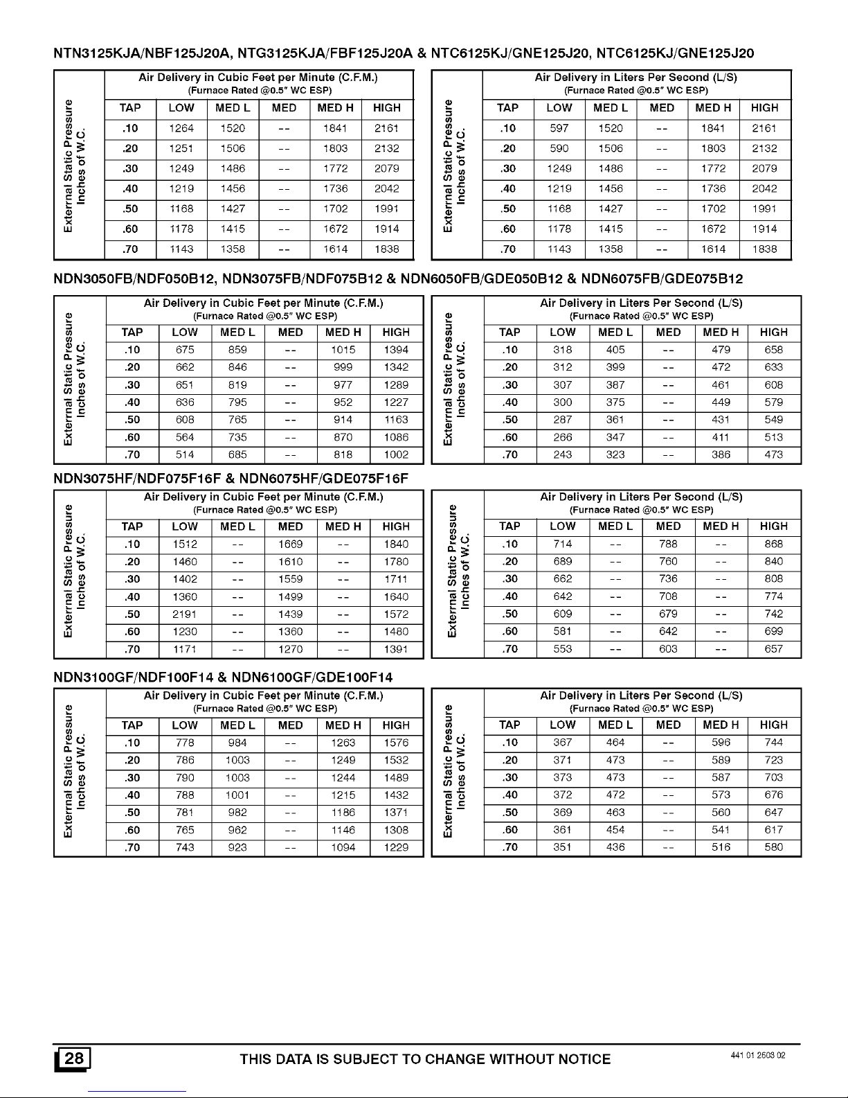
NTN3125KJA/NBF125J20A, NTG3125KJA/FBF125J20A & NTC6125KJ/GNE125J20, NTC6125KJ/GNE125J20
Air Delivery in Cubic Feet per Minute (C.F.M,)
(Furnace Rated @0,5"WC ESP)
TAP LOW MED L MED MED H HIGH
_ .10 1264 1520 -- 1841 2161
_ .20 1251 1506 -- 1803 2132
o
_o
_ .30 1249 1486 -- 1772 2079
o .40 1219 1456 -- 1736 2042
5_
.50 1168 1427 -- 1702 1991
w .60 1178 1415 -- 1672 1914
.70 1143 1358 -- 1614 1838
Air Delivery in Liters Per Second (L/S)
(Furnace Rated @0,5" WC ESP)
TAP LOW MED L MED MED H HIGH
,; .10 597 1520 -- 1841 2161
LJ
_ .20 590 1506 -- 1803 2132
o
_o
_ .30 1249 1486 -- 1772 2079
o .40 1219 1456 -- 1736 2042
5-=
.50 1168 1427 -- 1702 1991
w .60 1178 1415 -- 1672 1914
.70 1143 1358 -- 1614 1838
NDN3050FB/NDF050B12, NDN3075FB/NDF075B12 & NDN6050FB/GDE050B12 & NDN6075FB/GDE075B12
Air Delivery in Cubic Feet per Minute (C.F.M.)
(Furnace Rated @0,5" WC ESP)
LOW MED L
d 675 859
o 662 846
_o
_ 651 819
o 636 795
5=
-- 608 765
× 564 735
LU
514 685
TAP MED MED H HIGH TAP HIGH
.10 -- 1015 1394 _ d .10 658
.20 -- 999 1342 .£ .20 633
o
.30 -- 977 1289 _ _ .30 608
.40 -- 952 1227 _ _ .40 579
E_
.50 -- 914 1163 .50 549
.60 -- 870 1086 × .60 513
w
.70 -- 818 1002 .70 473
Air Delivery in Liters Per Second (L/S)
(Furnace Rated @0.5" WC ESP)
LOW MED L MED MED H
318 405 -- 479
312 399 -- 472
307 387 -- 461
300 375 -- 449
287 361 -- 431
266 347 -- 411
243 323 -- 386
NDN3075HF/NDF075F16F & NDN6075HF/GDE075F16F
Air Delivery in Cubic Feet per Minute (C.F.M.)
(Furnace Rated @0.5" WC ESP)
TAP LOW MED L MED MED H HIGH
_ O. .10 1512 -- 1669 -- 1840
o
_ .20 1460 -- 1610 -- 1780
(13
•cn .30 1402 -- 1559 -- 1711
o .40 1360 - - 1499 - - 1640
5-=
.50 2191 - - 1439 - - 1572
x
LU .60 1230 -- 1360 -- 1480
.70 1171 -- 1270 -- 1391
Air Delivery in Liters Per Second (L/S)
,_ (Furnace Rated @0.5" WC ESP)
u_ TAP LOW MED L MED MED H HIGH
u)
,=
O .10 714 -- 788 -- 868
:= % .20 689 -- 760 -- 840
8 .30 662 -- 736 -- 808
o .40 642 -- 708 -- 774
E£
.50 609 -- 679 -- 742
× .60 581 642 699
.70 553 -- 603 -- 657
NDN3100GF/NDF100F14 & NDN6100GF/GDE100F14
Air Delivery in Cubic Feet per Minute (C.F.M.)
(Furnace Rated @0.5" WC ESP)
TAP LOW MED L
8 d .10 778 984 -- 1263
o .20 786 1003 -- 1249
_o
8 .30 790 1003 -- 1244
I J=
o .40 788 1001 -- 1215
5_=
.50 781 982 -- 1186
I_ .60 765 962 -- 1146
.70 743 923 -- 1094
MED MED H HIGH TAP HIGH
1576 _ d .10 744
1532 .£ .20 723
o
1489 _ 8 .30 703
1432 _ o .40 676
E_=
1371 _ .50 647
1308 _ .60 617
1229 .70 580
Air Delivery in Liters Per Second (L/S)
(Furnace Rated @0.5" WC ESP)
LOW MED L MED MED H
367 464 -- 596
371 473 -- 589
373 473 -- 587
372 472 -- 573
369 463 -- 560
361 454 -- 541
351 436 -- 516
THIS DATA IS SUBJECT TO CHANGE WITHOUT NOTICE 44101260302
Page 29

NDN3100KF/NDF100F20&NDN6100KF/GDE100F20
Air Delivery in Cubic Feet per Minute (C.F.M.)
(Furnace Rated @0.5" WC ESP)
TAP LOW MED L MED MED H HIGH
d .10 1305 1405 -- 1805 2141
'.,.) .20 1258 1475 -- 1743 2064
_o
_ .30 1241 1424 -- 1698 1981
"_ .40 1227 1383 -- 1636 1902
__-= .50 1178 1343 -- 1563 1818
× .60 1103 1279 -- 1491 1740
LU
.70 1029 1185 -- 1390 1644
(n
==d
.£
_o
E-=
x
LU
Air Delivery in Liters Per Second (L/S)
(Furnace Rated @0.5" WC ESP)
TAP LOW MED L MED MED H HIGH
.10 616 706 -- 852 1011
.20 594 688 -- 823 974
.30 586 672 -- 801 935
.40 579 653 -- 772 898
.50 556 634 -- 738 858
.60 521 604 -- 704 821
.70 486 559 -- 656 776
NDN3125KJ/NDF1 25J20 & NDN6125KJ/GDE125J20
Air Delivery in Cubic Feet per Minute (C.RM.)
(Furnace Rated @0,5" WC ESP)
ca TAP LOW MED L MED MED H HIGH
d .10 1333 1573 -- 1840 2148
",.) .20 1294 1544 -- 1816 2093
_o
_ .30 1266 1500 -- 1776 2041
"_ .40 1240 1467 -- 1726 1981
5_=
.50 1175 1419 -- 1665 1906
× .60 1141 1357 -- 1607 1828
LU
.70 1054 1308 -- 1538 1751
_d
.'.2-
E_=
x
LU
Air Delivery in Liters Per Second (L/S)
(Furnace Rated @0.5" WC ESP)
TAP LOW MED L MED MED H HIGH
.10 629 742 -- 868 1014
.20 611 729 -- 857 988
.30 598 708 -- 838 963
.40 585 692 -- 815 935
.50 555 670 -- 786 900
.60 539 641 -- 759 863
.70 497 617 -- 726 826
NTC6100GF/GNE100F14
Air Delivery in Cubic Feet per Minute (C.F.M.)
(Furnace Rated @0,5" WC ESP)
TAP LOW MED L MED MED H HIGH
® .10 815 1043 -- 1324 1649
_ .20 783 1030 -- 1302 1616
_ .30 755 1021 -- 1280 1592
.40 735 989 -- 1255 1546
_ .50 704 968 -- 1218 1502
.60 668 941 -- 1171 1425
w
.70 646 881 -- 1100 1353
NTC6100KF/GNE100F20 & NTN6100KF/NNE100F20
Air Delivery in Cubic Feet per Minute (C.F.M.)
._ (Furnace Rated @0.5"WC ESP)
TAP LOW MED L MED MED H HIGH
.10 1278 1546 -- 1822 2302
.9 _ .20 1264 1543 -- 1784 2731
_"6 .30 1244 1499 -- 1737 2171
o)
'_ ',_ .40 1212 1471 -- 1683 2098
E_
.50 1185 1417 -- 1641 2012
w .60 1178 1367 -- 1574 1921
.70 1119 1304 -- 1495 1826
NTC61 50KJ/GNE150J20
03
_o."
.£
uJ
Air Delivery in Liters Per Second (L/S)
(Furnace Rated @0.5" WC ESP)
TAP LOW MED L MED MED H HIGH
.10 385 492 -- 625 778
.20 370 486 -- 615 763
.30 356 482 -- 604 751
.40 347 467 -- 592 730
.50 332 457 -- 575 709
.60 315 444 -- 553 673
.70 305 415 -- 519 639
e3
e)
_-o."
.£
E_=
e)
full
Air Delivery in Liters Per Second (L/S)
(Furnace Rated @0.5" WC ESP)
TAP LOW MED L MED MED H HIGH
.10 603 730 -- 860 1087
.20 597 728 -- 842 1289
.30 587 708 -- 820 1025
.40 572 694 -- 794 990
.50 559 669 -- 775 950
.60 556 645 -- 743 907
.70 528 615 -- 706 862
Air Delivery in Cubic Feet per Minute (C.F.M.)
"_ (Furnace Rated @0.5" WC ESP)
61
TAP LOW MED L MED MED H HIGH
0," .10 1357 1542 -- 1709 2073
._.2
_"6 .20 1325 1525 -- 1750 2040
.30 1290 1503 -- 1761 2014
E -= .40 1270 1480 -- 1740 1975
.50 1243 1464 -- 1710 1953
LU
.60 1225 1430 -- 1650 1885
.70 1195 1401 -- 1602 1827
.=
Air Delivery in Liters Per Second (L/S)
(Furnace Rated @0.5" WC ESP)
TAP LOW MED L MED MED H HIGH
.10 641 728 -- 807 978
.20 625 720 -- 826 963
.30 609 709 -- 831 951
.40 600 699 -- 821 932
.50 587 691 -- 807 922
.60 578 675 -- 779 890
.70 564 661 -- 756 862
._'-2
E_=
UJ
44_o_260s02 THIS DATA IS SUBJECT TO CHANGE WITHOUT NOTICE [_
Page 30

B
o
o
o
CONNECTION DIAGRAM
FIELD
CONNECTION
BOX
60HZ _-
'------1K
INTER- r_-.|
LOCK 11Zl
SWITCH I_
ITRANSFORMERI
I L
iI
_ _L
I
I I
I,
DANGER: ELECTRICAL SHOCK HAZARD
DISCONNECT BEFORE SERVICING
SPARK I_- -- -- --
24V _-
24V GND
GND
PV - _
MVIPV
MV -"
LADDER DIAGRAM
i_ IGNTER
J SENSOR
-It,
-3 n
G I
/ I
G- -I I
--BL-_PV L U-
I
I
_' --Y-- _" MV/PV I I
] I I
-o- .._ MV ii
IGNITION MODULE I GAS
, VALVE I I
O I
L W , y l
BK
----- II ROLLOUTSW,TOH I '1
1 TO 3 IN SERIES I
DEPENDING I VENT SAFETY I
-- -- NOT ON ALL I I
_---R-- _ --R-I _ -I
L! _ Ik_ ii I
_s_ _ _)_1 ! r ...... J MAIN UMIT R I
-- "" (_)_, I r____R____:_.J I i
__ -- I . _,JAUX, NOT _ I ,
--BL-- J I b_ __R__ ON ALL MODELS j I
--F_ BK- 11" BL_ i_}_ __ BL__ __--_ __ BL__ j
--(3" L ................ I
',..p.J _
ITJQI3D 3ELAy FURNACE AUX, LIMIT
HOT 115V-60HZ NEUTRAL
_L.s< °-II' _ ,
>
INTERLOCK GND.
WITCH MODULE
$1 COOL HI N i
II - -_-"_._ ......... ._MOTOR_. _ --_
II _mR II
II _ II
II II
£
m
CAPACITOR
_|_ .....i i ]_I_I_I_1r_ CONTROL
_FF U_
-,_,----- I-T-E-r-._ _
THERMOST ; 2X
0TO 2IN
SERIES
DEPENDING
ON MODEL
SPEED TAP CODE
BLACK H_ BLUBMLO
ORANGE MHF RED LO
-- LINE VOLTAGE FACTORY
LiNE VOLTAGE FIELD
-- -- LOW VOLTAGE FACTORY
-- LOW VOLTAGE FIELD
_ INTERNAL CiRCUiT BOARD WiRiNG
PRESSURE SWITCH
1 TO 3 IN SERIES
DEPENDING ON
MODEL
COLOR CODE
BLUE BL
BROWN BR
GREEN G
ORANGE O
RED R
WHITE W
YELLOW Y
r SEE TABLE _N MANUAL FOR CF.M VS E.S.P TO DETERMINE PROPER HEATING AND COOLING SPEED CONNECTIONS
...... =
_==_e.0..0oo=_ =4
_:: _TRANSFORMER _ =
ROLLOUT SWITCH IGNITER
-rmm-,;_pOE_%_%%oE_....... SENSOR
xu s_c_ / MODELSl _VGNI_ ' -1
6u'o3 / '_I
24 VAC I GND I1_ J
.......o_ MA,NUM,T'_n g
A A j MWPVII 11--_ "MWPVI
_ 0_--_ M_u H _._ I
< I_ 40 AUX NOTON
Z Z_ ALLMODELS II rI GAS
O _O- .......... -I I VALVE
u_ (D I
-0- -0
r <) c 50-- --1 AUK, LIMIT PRESSURE SWITCH
__ 0 TO 2 IN 1 TO 3 IN SERIES
I
I SERIES DEPENDING ON MODEL
_- I . • . DEPENDING
I _ I ONMODEL
THERMOSTAT
iF ANY OF THE ORiGiNAL WiRE AS SUPPUED WiTH THE APPLIANCE
MUST BE REPLACED• _TMUST BE REPLACED WITH TYPE
AWM - 105°C WIRE OR ITS EQUIVALENT
O O
m Z
o oo
oo
o_o
> *_-] _ "
0_oo
©m
co
11
>
Z
o
O
Z
° _
_1_ _ o
m_
_q_ >
Z> _z O
om_o O
zZ_OZ o
_ZOZo >
o_ o_q .
o_ o
_>_'
_m_
>o -I m m
I012723-A
Q
5
,-11
5
"11
-rl
Page 31

13.NTG3/FBF& NTN3/NBF
/B
DD
EE
D
E
-AA
U
22
10
14
25-22-27
441 01 2603 02
Page 32

I Replacement Parts - NTG3/FBF (NaturalGas) I
Models - NTG305OFBG1, NTG3075FBG1, NTG3075HFG1, NTG3100GFG1, NTG3100KFG1, NTG3100LJG1, NTG3125KJG1,
NTG3125LJG1: & FBF050B12G1, FBFO75B12G1, FBFO75F16G1, FBF100F14G1, FBF10OF2OG1, FBF100J22G1, FBF125J20G1,
FBF125J22G1
Replacement part supplied will be current active part. For parts not listed, consult place of purchase.
Key Description
No. Functional
HeatExchanger
2 BtowerWheel 10-10 DD
10-8 DD
11-10DD
3 Switch,AuxiliaryLimit
4 BlowerMotor 115V-1/3HP
115V-1/2 HP
115V-1/3 HP
115V-3/4 HP
115V-3/4 HP
115V-3/4 HP
5 Motor MountKit
6 Control,FanTimer
6A Control,Module
7 Transformer,40VA
8 Capacitor 5mf 370V
10mf370V
7.5mf370V
40mf370V
9 SwitchDoor
10 BurnerAssembly
11 Pilot/IgnitorNatural
12 PitotOrifice,NAT(.018)
13 Orifice, #42 NAT
14 Tube,Pilot
15 Manifold
16 Valve,Natural
17 Switch,Limit 270°F
250°F
150°F
195°F
190°F
170°F
18 Tubing,Silicone24"
19 CombustionBlowerAssemly
20 RoIIoutSwitch,Limit
21 Switch,Pressure
22 Heat ExchangerGaskets
23 Heat ExchangerFrtPartition
Part
Number
1011544
1012406
1012407
1011364
1011363
1012408
601210
600587
1011420
1000735
1012514
1012119
1013341
1011906
1010263
1011404
609227
522020024
1011927
1011449
1012722
1094954
1094956
1094239
1012176
1010886
1012382
1012383
1012384
1012385
1011477
503211
1011351
1011943
1011044
1011945
1011458
1011459
1011460
1011461
1005597
1320365
1009169
1320364
1320363
1008445
1095242
2971255
1010975
1094863
1005549
1010898
2480904
2480905
2480906
2480907
1011451
1012409
1012410
1008072
1008071
1012411
050FBG1/
050B12G1
1
2
1
1
1
1
1
1
1
2
1
1
1
2
075FBG1/
075B12G1
2
1
1
1
1
1
1
1
1
3
1
1
1
1
1
1
2
1
2
075HFG1/
075F16G1
1
2
1
1
1
1
1
1
1
1
3
1
1
NTG3/FBF
100GFG1/ 100LJG1/
100F14G1 100J22G1
1
1
1
1
2 2
1
1
1
1
1 1
1 1
1 1
1
1
1 1
1 1
1 1
1 1
4 4
1 1
1 1
1 1
1
1
1 1
1 1
2 2
1 1
2 2
1
1
100KFG1/
100F20G1
1
1
1
1
1
1
4
1
1
1
1
2
125KJG1/
125J20G1
1
1
2
1
1
1
1
1
1
1
5
1
1
2
125LJG1/
125J22G1
1
2
1
1
1
1
1
1
1
5
1
1
1
2
441 01 2603 02
Page 33

I Replacement Parts - NTG3/FBF (NaturaI s, I
Models - NTG305OFBG1, NTG3075FBG1, NTG3075HFG1, NTG31 OOGFG1, NTG3100KFG1, NTG3100LJG1, NTG31 25KJG1,
NTG31 25LJA: & FBFO5OB1 2G1, FBFO75B1 2G1, FBFO75F1 6G1, FBF100F1 4G1, FBF100F2OG1, FBF100J22G1, FBF1 25J20G1,
FBF1 25J22A
Replacement part supplied will be current active part. For parts not listed, consult place of purchase.
NTG3/FBF
Key Description
No, Non- Functional
Top
B FieldConnectBox
C Cover,FieldConnect
D Gasket,Collector
Collector
F Gasket,CombustionBlower
H Door,Louvered
Door,Blower
Shield,Burner
M Bracket,Pilot
O ManifoldSupportBracket
U FanTimer Bracket
W BlowerHousing
BlowerCutoff
Y BlowerHanger
AA StrapCapacitor
BB Rail,BlowerSlide
LL Bracket,Control
NN Partition,Blower
)( PARTNOTILLUSTRATED
)( WireHarnessAsy. LowVolt
)( Manual,Homeowners
)( Manual, Installation&Tech
Part
Number
1013295
1013296
1013297
1013298
1011941
1010360
1093661
1093662
1093663
1011045
1011048
1011052
1011055
1011379
1013324
1013316
1013317
1013303
1013304
1013305
1011335
1011336
1011337
1010901
1011820
1012321
1013131
1013132
1013128
721020008
721020013
1010690
1095020
1095022
57059
1011448
1013456
1013457
1013461
1011868
44102200105
44101260301
050FBG1/
050B12G1
1
1
1
1
1
2
1
1
1
2
1
2
1
1
1
1
1
075FBG1/
075B12G1
1
1
1
1
1
1
1
1
1
1
2
1
1
1
2
1
2
1
1
1
1
1
075HFG1/
075F16G1
1
1
1
1
1
1
1
1
2
1
1
1
1
100GFG1/
100F14G1
1
1
1
1
1
1
1
1
2
1
1
1
2
1
2
1
1
1
1
1
100LJG1/
100J22G1
1
1
1
1
1
1
1
1
2
1
1
2
1
1
1
1
100KFG1/
100F20G1
1
1
1
1
1
1
1
1
2
1
1
1
1
125KJG1/
125J20G1
1
1
1
1
1
1
2
1
1
1
1
125LJG1/
125J22G1
1
1
1
1
1
1
2
1
1
2
1
1
1
1
441 01 2603 02
Page 34

I Replacement Parts - NTN3/NBF (.aturaJGas)
Models - NTN305OFBG1, NTN3075FBG1, NTN3075HFG1, NTN3100KFG1, NTN31 OOKJG1, NTN3100LJG1, NTN31 25KJG1,
NTN3125LJG1: & NBFO50B12G1, NBFO75B12G1, NBFO75F16G1, NBF10OF14G1, NBF1OOF2OG1, NBF1OOJ22G1, NBF125J20G1,
NBF1 25J22G1
Replacement part supplied will be current active part. For parts not listed, consult place of purchase.
Key Description
No. Functional
HeatExchanger
2 BlowerWheet 10-10 DD
10-8 DD
11-10 DD
3 Switch,AuxiliaryLimit
4 Blower Motor 115V-1/3HP
115V-1/2HP
115V-3/4 HP
115V-3/4 HP
115V-3/4 HP
5 Motor MountKit
6 Control,FanTimer
6A Controt, Module
7 Transformer,40VA
8 Capacitor 10mf370V
5mf370V
40mf370V
9 Switch Door
10 BurnerAssembly
11 Pilot/IgnitorNatural
12 PilotOrifice,NAT(.018)
13 Orifice, #42 NAT
14 Tube,Pilot
Manifold
16 Valve,Natural
17 Switch,Limit 270°F
250°F
195°F
130°F
190°F
170°F
18 Tubing,Silicone24"
19 CombustionBlowerAssem
20 RolloutSwitch,Limit
21 Switch,Pressure
22 HeatExchangerGaskets
23 HeatExchangerFrt Partition
Part
Number
1011544
1012406
1012407
1011364
1011363
1012408
601210
600587
1011420
1000735
1012514
1012119
1011404
1010263
1011906
609227
522020024
1011927
1011449
1012722
1094956
1094954
1012176
1010886
1012382
1012383
1012384
1012385
1011477
503211
1011351
1011943
1011944
1011945
1011458
1011459
1011460
1011461
1005597
1320365
1009169
1320363
1320364
1008445
1095242
2971255
1010975
1094863
1005549
1010898
2480904
2480905
2480906
2480907
1011451
1012409
1012410
1008072
1008071
1012411
050FBG1/ 075FBG1/ 075HFG1/
050B12G1 075B12G1 075F16G1
1
1
2
1
1
1
1
1
1
2
1
1
1
2
1
2
1
1
1
1
1
1
1
3
1
1
1
1
2
1
2
1
2
1
1
1
1
1
1
1
1
3
1
1
NTN3/NBF
100KFG1/ 100KJG1/
100F20G1 100J20G1
1
1
1 1
2 2
1
1
1 1
1 1
1 1
1 1
1 1
1 1
1 1
1 1
1 1
4 4
1 1
1 1
1 1
1
1 1
1 1
2 2
1 1
2 2
1
1
100LJG1/
100J22G1
1
1
1
1
1
1
4
1
1
1
1
2
125KJG1/ 125LJG1/
125J20G1 125J22G1
1
1
2
1
1
1
1
1
1
1
1
1
5
1
1
2
1
1
2
1
1
1
1
1
1
1
5
1
1
1
2
I
_] 441 01 2603 02
Page 35

I Replacement Parts - NTN3/NBF (Natural s, I
Models - NTN3050FBG1, NTN3075FBG1, NTN3075HFG1, NTN3100KFG1, NTN3100KJG1, NTN3100LJG1, NTN3125KJG1,
NTN3125LJG1: & NBF050B12G1, NBF075B12G1, NBF075F16G1, NBF100F14G1, NBF100F20G1, NBF100J22G1, NBF125J20G1,
NBF125J22A
Replacement part supplied will be current active part. For parts not listed, consult place of purchase.
NTN3/NBF
Key Description
No. Non- Functional
Top
B FieldConnectBox
C Cover,FieldConnect
D Gasket,Collector
Collector
F Gasket,CombustionBlower
H Door,Louvered
Door,Blower
Shietd,Burner
M Bracket,Pilot
O ManifoldSupportBracket
U FanTimer Bracket
W BlowerHousing
BlowerCutoff
Y BlowerHanger
AA StrapCapacitor
BB Rail,BlowerSlide
EE NOxBaffle
LL Bracket,Control
NN Partition,Blower
)( PARTNOT ILLUSTRATED
)( Wire HarnessAsy.LowVolt
)( Manual, Homeowners
)( Manual, Installation&Tech
Part
Number
1013295
1013296
1013297
1013298
1011941
1010360
1093661
1093662
1093663
1011047
1011050
1011053
1011056
1011379
1013324
1013316
1013317
1013303
1013304
1013305
1011335
1011336
1011337
1010901
1011820
1012321
1013131
1013132
1013128
721020008
721020013
1010690
1095020
1095022
57059
1009876
1011448
1013456
1013457
1013461
1011868
44102 200106
44101 260301
050FBG1/
050B12G1
1
1
1
1
1
2
1
1
2
1
2
2
1
1
1
1
1
075FBG1/
075B12G1
1
1
1
1
1
1
1
1
1
1
2
1
1
2
1
2
3
1
1
1
1
1
075HFG1/
075F16G1
1
1
1
1
1
1
1
1
2
1
2
3
1
1
1
1
100KFG1/
100F20G1
1
1
1
1
1
1
1
1
2
1
2
4
1
1
1
1
100KJG1/
100J20G1
1
1
1
1
1
1
1
1
2
1
2
4
1
1
1
1
100LJG1/
100J22G1
1
1
1
1
1
1
1
1
2
1
1
2
4
1
1
1
1
125KJGt/
125J20G1
1
1
1
1
1
1
1
2
1
2
5
1
1
1
1
125LJG1/
125J22G1
1
1
1
1
1
1
2
1
1
2
5
1
1
1
1
441 01 2603 02
Page 36

14.NDN3/NDF
MM
A
$S
BB
LL
19\
22
20
22
25-23-14
441 01 2603 02
Page 37

I Replacement Parts - NDN3/NDF I
Models - NDN305OFBG1, NDN3075FBG1, NDN3075HFG1, NDN3100GFG1, NDN3100KFG1, NDN3125KJG1
NDFO50B12G1, NDFO75B12G1, NDFO75F16G1, NDF10OF14G1, NDFIOOF2OG1, NDF125J20G1
Replacement part supplied will be current active part. For parts not listed, consult place of purchase.
Key Description
No. Functional
t HeatExchAssembty
2 SlowerWheel 10-1ODD
10-8DD
11-10DD
3 Switch, Limit(Auxiliary)
4 SlowerMotor 115V1/3HP
115V1/2HP
115V1/2HP
115V3/4 HP
tt5V 3/4 HP
5 MotorMountKit
6 Control,FanTimer
6A ControlModule
7 Transformer,40VA
8 Capacitor 10mf 370V
7.5mf370V
5mf370V
9 Switch Door
10 BurnerAssembly
11 Pilot,Natural&LP
12 Orifice,Pilot,Nat. (.018)
13 Orifice,#42, Nat.
14 Tube, Pilot
15 Manifold
16 Valve,Natural
17 Switch, Limit 210°F
260°F
195°F
220°F
150°F
18 Tubing,Silicone,(24")
19 CombustionBlwr Assb
20 RolloutSwitch,Limit
21 Switch, Pressure
22 Gasket,HeatExchanger
23 Partition,FrontHtExchanger
Part
Number
1011544
1012406
1012407
1011364
1012408
601210
600587
1011420
1320368
1012514
1012119
1013341
1011404
1010263
609227
522020024
1011927
1011449
1012722
1094956
1094239
1094954
1010886
1012382
1012383
1012384
1012385
1011477
503211
1011351
1011943
1011944
1011945
1011458
1011459
1011460
1011461
1005597
34335001
1320366
1320363
1320367
1065638
2971255
1010975
1005549
1010898
2480904
2480905
2480906
2480907
1011451
1012409
1012410
1008072
1012411
050FBG1/
050B12G1
1
1
1
1
1
1
1
1
1
1
t
2
1
1
1
1
1
2
075FBG1/
075B12G1
1
1
1
1
1
1
1
1
3
1
1
1
1
NDN3/NDF
075HFG1/ t00GFG1/
075F16G1 100F14G1
1
1
1
]
]
]
]
]
]
]
]
3
]
]
]
]
]
]
]
]
2
]
100KFG1/
100F20G1
1 1
1
1
1 1
1
1
t ;
] 1
] 1
] 1
1
]
] 1
] 1
] 1
] t
4 4
] 1
] 1
]
1
] 1
] 1
] 1
] 1
2 2
] 1
125KJG1/
125J20G1
1
1
1
1
1
1
1
1
1
t
5
1
1
1
1
1
441 01 2603 02
Page 38

I Replacement Parts - NDN3/NDF I
Models - NDN305OFBG1, NDN3075FBG1, NDN3075HFG1, NDN3100GFG1, NDN3100KFG1, NDN3125KJG1
NDFO50B1 2G1, NDFO75B1 2G1, NDFO75F1 6G1, NDF1 0OF1 4G1, NDFIOOF2OG1, NDF1 25J20G1
Replacement part supplied will be current active part. For parts not listed, consult place of purchase.
Key Description
No, Non- Functional
Top
B FieldConnectBox
C Cover,FieldConnect
D Gasket,Collector
Collector
F Gasket,CombustionBlwr
H Door,Louvered
Door,Blower
M Bracket,Piiot
O ManifoldSupportBracket
U Support,Control
W BlowerHousing
BlowerCutoff
Y BlowerHanger
AA Clamp,Capacitor
BB Rail,BlowerSlide
EE NOxBaffle
LL Bracket,Ignition Module
MM Filter Holder
NN Flue Pipe
CO VentPipeShield
PP VentShield Endplate
QQ Plate, FiII-in
RR Partition,Blower
SS BurnerShield
)( PART NOTILLUSTRATED
)( Wire Harness
)( Manual, Homeowners
)( Manual, Installation
)( Manual,TechSupport
Part
Number
1013299
1013302
1013300
1013301
1011941
1010360
1093661
1093662
1093663
1011047
1011050
1011053
1011056
1011379
1013334
1013335
1013336
1013310
1013311
1013312
1010901
1011820
1011178
1010579
1013129
1010580
721020008
721020013
33403100
1095020
33406100
1009876
1011448
33411100
613193
2311160
57083
1011071
1011072
1011073
1013476
1013477
1013474
1013475
1011335
1011336
1011337
1012720
44102200105
44101260300
44103260900
050FBG1/
050B12G1
1
1
1
1
1
2
1
1
1
2
1
2
2
1
1
1
1
2
1
1
1
1
1
075FBG1/
075B12G1
1
1
1
1
1
2
1
1
1
2
1
2
3
1
1
1
1
2
1
1
1
1
1
NDN3/NDF
075HFG1/ 100GFG1/
075F16G1 100F14G1
1
1
1
1
1
1
1
2
1
1
1
2
1
2
3
1
1
1
1
2
1
1
1
1
1
1
1
100KFG1/
100F20G1
1 1
1 1
1 1
1 1
1 1
1 1
1 1
1 1
2 2
1 1
1
1
1 1
2 2
1 1
2 2
4 4
1 1
1 1
1 1
1 1
2 2
1 1
1 1
1 1
1 1
1 1
1 1
125KJG1/
125J20G1
1
1
1
1
1
2
1
2
1
2
5
1
1
1
1
2
1
1
1
1
441 01 2603 02
Page 39

DANGER: ELECTRICAL SHOCK HAZARD
CONNECTION DIAGRAM
DISCONNECT BEFORE SERVICING
FIELD
CONNECTION .BK SENSOR
BOX / r---rl--
_r_ _Eu-'Y_"_O -- /FXHmJST_ TRANSFORMER I I I I I
_HL __ \R, nWFR/ _ i]_
BK I F,-_ -- ..... _ '9
__ ;----_L_ I 0_s_
--- II r------ VALVE I I I
BK -w-- IROLLOUT SWITCF
i I Ii TO 3 IN SERIES B,L i i
INTER- r_)] w I I I DEPENDING ON MODEL ' I I
LOCK II )1 i I I-- A- I K
% -- II I , VENT SAFETY I II I
I i , I I NOT ON ALL i 6
I II IB MODELS R II II
- gt - .... 14.J
_" _ I_J_-4-= ....... :i
...... y BK-- FURNACE AUX, LIMIT PRESSURE
_F_ LI 10 CONTROL I TO 2 iN SWITCH
i i _L_Y E_ y C ] Y W R
_ _' t C t_ SERIES I TO 3 IN
7? _/l/ 011N_NNNII DEPENDING SERIES
- ON MODEL DEPENDING
II -_u _ _#:L __
_ill I ON MODEL
| ,,_-o-!FiB COLORCOOL
| I I _ SPEED TAP CODE
__ I Y W BLACK BK
0 i i BLACK -Hl 81UE-NL[ BLUE BL
CAPACITOR I _.&_ ORANGE-MHI RED -LC RRnWN m R
_ I ILINE VOLTAIGE FACTORY GREEN _G
ILINE VOLTAGE FIELD ORANGE 0
. I LOW VOLTAGE FACTORY REO R
THERMOSTAT I LOW VOLTAGE FIELD WHITE
INTERNAL CIRCUIT BOARD WIRIN[ YELLOW
LADDER DIAGRAM
NOT II5V-BBHZ NEUTRAL
#< odl, >J_
_ZNTERLOCK GNOo
SWITCH MODULE
II _c°°_° _° "_-zo_& II
ii _--_ CAPACITOR
II CAPACITOR II
b a
= _ _OHUM HUM_ :
s2 llSV TRANSFORMER N iI
ROLLOUT SWITCH 24 VOLT HOT_
,r_ z_._.v_ I TO 3 IN SERIES /
I r OEPENO]NG_ON MOOEL 24MVCoLT _ /
' ' F_- SENSORl/
X_R S_C / VENT_SAFETY E_,_--I / /
MA_N NOT ON LL IGNITER II I / /
_o/ _ MODELS I II I I / w
LIMIT I • //
L O 3) ...... 4 , _ I ]
r,-oc 5o--11 AUX, LIMIT PRESSURE SWITCH \\ I
|_ I Ito_ IN 1tO 3IN SERIES\\
|_ I SERIES DEPENDmGCN_ODE_\I
-L I I I I DEPENDING __ IIILLI
= I _ IoN _DOE_F-- --_q-vETJW
___ .... m FsEw_S_ R E \
.TFHAE#yMoOFSTT_ET ORIGINAL WIRE AS SUPPLED wITEHFITHEOcUpTptIUAT_
MUST BE REPLACED, IT MUST BE REPLACED WITH TYPE
AWM - I_5'C WIRE OR iTS EOUIVALENT_
SEE TABLE IN MANUAL FOR C,PIM. VS, E.S.P. TO DETERMINE PROPER HEATING AND COOLING SPEED CONNECTIONS.
o®m
c_ "q O
_mp
S_g
,.<
m
_CB,
E_
_>#$ g
Roog g
' _o_O
Z .__ E]
Fm
1_II742-A
m
m
m
Page 40

NTC6/GNE& NTN6/NNE
EE
AA
/J
16
22
14
25-22-29
_] 441 01 2603 02
Page 41

I Replacement Parts - NTC6/GNE (NaturalGas) I
Models - NTC605OFBG1, NTC6075FBG1, NTC6075HFG1, NTC6100GFG1, NTC6100KFG1, NTC6100KJG1, NTC6125KJG1,
NTC6150KJG1: GNEO50B12G1, GNEO75B12G1, GNEO75F16G1, GNE100F14G1, GNEIOOF2OG1, GNEIOOJ2OG1, GNE125J20G1
& GNE150J20G1
Replacement part supplied will be current active part. For parts not listed, consult place of purchase.
NTC6/GNE
Key Functional
No. Description
1 HeatExchanger
2 BlowerWheet 10-10DD
10-8DD
11-10DD
12-12DD
3 Switch,Auxiliary Limit
4 BIowerMotor 115V1/3liP
115V1/2HP
115V1/2HP
115V3/4HP
115V3/4liP
5 MotorMountKit
6 Control,FanTimer
7 Transformer,40VA
8 Capacitor 10mf370V
5mf370V
7.5mf370V
9 SwitchDoor
10 BurnerAssembly
11 Pilot, Natural& LP
12 PilotOrifice,NAT(.018)
13 Orifice, #42 NAT
14 Tube,Pilot
15 Manifold
16 Valve, Natural&LP
17 Switch,Limit 270°F
145°F
130°F
150°F
250°F
140°F
18 Tubing,Silicone24"
19 CombustionBlowerAssem
20 l!ollout Switch, Limit
21 Switch,Pressure
22 HeatExchangerGaskets
23 HeatExchangerFrt Partition
Part
Number
1011544
1012406
1012407
1011364
1011363
1012408
1011366
601210
600587
1011420
1011433
1000735
1012514
1012119
1013341
1011404
1010263
609227
522020024
1002804
1011927
1012722
1094956
1094954
1094239
1010886
1012382
1012383
1012384
1012385
1013066
1008731
503211
1011351
1011943
1011944
1011945
1011458
1011459
1011460
1011461
1011462
1011421
1320365
1320363
1320364
1320362
1009169
1008445
2971255
1010975
1005549
1010898
2480904
2480905
2480906
2480907
2480908
1008068
1008072
1008071
1008074
1012409
1012410
1012411
1009524
050FBG1/
050B12G1
1
2
1
1
1
1
1
2
1
1
1
2
1
2
075FBG1/
075B12G1
2
1
1
1
1
1
1
3
1
1
2
1
1
1
075HFG1/
075F16G1
2
1
1
1
1
1
1
1
3
1
1
2
1
1
1
100GFG1/
100F14G1
2
1
1
1
1
1
1
1
1
1
4
1
1
1
1
1
1
2
1
100KFG1/
100F20G1
1
2
1
1
1
1
1
1
1
4
1
1
1
1
1
2
1
100KJG1/
100J20G1
1
2
1
1
1
1
1
1
1
1
4
1
1
1
1
28 Ignitor/Sensorwith clip 1 1 1 1
441 01 2603 02
1
1
2
1
125KJG1/ 150KJG1/
125J20G1 150J20G1
1 ;
1
1
2 2
1 ;
1 1
1 1
1 1
1 1
1
1
1 1
1 1
5 6
1 1
1
1
1 1
1 1
1 1
2 2
1 1
2
1
1 1
Page 42

I Replacement Parts - NTC6/GNE (NaturalGas) I
Models - NTC6050FBG1, NTC6075FBG1, NTC6075HFG1, NTC6100GFG1, NTC6100KFG1, NTC6100KJG1, NTC6125KJG1,
NTC6150KJG1: GNE050B12G1, GNE075B12G1, GNE075F16G1, GNE100F14G1, GNE100F20G1, GNE100J20G1, GNE125J20G1
& GNE150J20G1
Replacement part supplied will be current active part. For parts not listed, consult place of purchase.
NTC6/GNE
Key Non- Functional
No. Description
A Top
B FieldConnectBox
C Cover, FieldConnect
D Gasket,Collector
E Collector
F Gasket,CombustionBlower
H Door,LouveredNTC6only
NTC6only
NTC6only
GNEonty
GNEonty
GNEonty
J Door,Blower
M Bracket,Pilot
O ManifoldSupportBracket
U FanTimerBracket
W BlowerHousing
X BlowerCutoff
Y BlowerHanger
AA StrapCapacitor
BB Rail,BlowerSlide
NN Partition,Blower
CO Baffle,BurnerBox
PP Top,BurnerBox
QQ Cover,BurnerBox
RR Sightglass
)( PARTNOTILLUSTRATED
)( Wire HarnessAsy LowVolt
)( Fuse
)( Manual,Homeowners
)( Manual,Installation& Tech
Part
Number
1013295
1013296
1013297
1013298
1011941
1010360
1093661
1093662
1093663
1011045
1011048
1011052
1011055
1011057
1011379
1013331
1013332
1013333
1013325
1013326
1013327
1013303
1013304
1013305
1010901
1011450
1012321
1013131
1013132
1013128
1013130
721020008
721020013
721020015
1010690
1011921
1095020
57059
1013456
1013457
1013461
1013458
1011454
1011455
1011456
1011457
1011768
1011769
1011770
1011771
1011469
1011470
1011471
1011472
1011781
1011861
1083348
44102200105
44101230802
050FBG1/
050B12G1
1
1
1
1
1
2
1
1
1
2
1
2
1
1
1
1
1
075FBG1/
075B12G1
1
1
1
1
1
2
1
1
1
2
1
2
1
1
1
1
1
075HFG1/
075F16G1
1
1
1
1
1
1
2
1
1
2
1
2
1
1
1
1
1
1
100GFG1/
100F14G1
1
1
1
1
1
1
1
1
1
1
2
1
1
1
2
1
2
1
1
1
1
1
100KFG1/
100F20G1
1
1
1
1
1
1
1
1
1
1
2
1
1
1
2
1
2
1
1
1
1
1
100KJG1/
100J20G1
1
1
1
1
1
1
1
1
1
2
1
1
1
2
1
2
1
1
1
1
1
1
125KJG1/
125J20G1
1
1
1
1
1
1
1
1
1
2
1
1
1
2
1
2
1
1
1
1
1
1
1
150KJG1/
150J20G1
1
1
1
1
1
2
1
2
1
2
1
1
1
1
_] 441 01 2603 02
Page 43

I Replacement Parts - NTN6/NNE (NaturalGas) I
Models - NTN605OFBG1, NTN6075FBG1, NTN6075HFG1, NTN61OOKFG1, NTN61OOKJG1, NTN6125KJG1:
NNEO5OB12G1, NNEO75B12G1, NNEO75F16G1, NNEIOOF2OG1, NNE1OOJ2OG1 & NNE125J2OG1
Replacement part supplied will be current active part. For parts not listed, consult place of purchase.
NTN6/NNE
Key Functional
No, Description
1 Heat Exchanger
2 BlowerWheet 10-10DD
10-8DD
11-10DD
3 Switch,AuxiliaryLimit
4 BlowerMotor 115V1/3HP
115V1/2HP
115V3/4 HP
115V3/4 HP
5 Motor MountKit
6 Controt,Fan Timer
7 Transformer,40VA
8 Capacitor 10mf370V
5mf370V
9 SwitchDoor
10 BurnerAssembty
11 PiIot, Natural& LP
12 PilotOrifice,NAT(.018)
13 Orifice, #42 NAT
14 Tube,PiIot
15 Manifold
16 Valve,Natural& LP
17 Switch,Limit 270°F
145°F
130°F
250°F
140°F
18 Tubing,Silicone24"
19 CombustionBlowerAssembly
20 RolloutSwitch,Limit
21 Switch,Pressure
22 HeatExchangerGaskets
23 HeatExchangerFrontPartition
28 Ignitor/Sensorwithclip
Part
Number
1011544
1011364
1011363
1012406
1012407
1012408
601210
600587
1011420
1000735
1012514
1012119
1011404
1010263
609227
522020024
1011927
1012722
1094956
1094954
1010886
1012382
1012383
1012384
1012385
1008731
503211
1011351
1011943
1011944
1011945
1011458
1011459
1011460
1011461
1011421
1320365
1320363
1320364
1009169
1008445
2971255
1010975
1005549
1010898
2480904
2480905
2480906
2480907
1008068
1012409
1012410
1008072
1008071
1012411
1009524
050FBG1/
050B12G1
1
1
2
1
1
1
1
1
1
2
1
1
1
2
1
2
075FBG1/
075B12G1
1
2
1
1
1
3
1
1
2
1
075HFG1/
075F16G1
1
1
2
1
1
1
1
1
1
1
1
1
3
1
1
1
1
1
2
1
100KFG1/
100F20G1
1
1
1
1
1
1
4
1
1
1
1
1
2
1
1
1
100KJG1/
100J20G1
1
1
1
1
1
1
4
1
1
1
1
2
1
1
1
125KJG1/
125J20G1
1
1
1
1
1
1
1
5
1
1
1
2
1
441 Ol 2603 02 [_
Page 44

I Replacement Parts - NTN6/NNE (NaturalGas) I
Models - NTN605OFBG1, NTN6075FBG1, NTN6075HFG1, NTN6100KFG1, NTN6100KJG1, NTN6125KJG1:
NNE050B12G1, NNEO75B12G1, NNEO75F16G1, NNE10OF20G1, NNEIOOJ20G1 & NNE125J20G1
Replacement part supplied will be current active part. For parts not listed, consult place of purchase.
NTN6/NNE
Key Non-Functional
No. Description
Top
B FieldConnectBox
C Cover,FieldConnect
D Gasket,Collector
Collector
F Gasket,CombustionBlower
H Door,Louvered
Door,Blower
M Bracket,Pilot
O ManifoldSupportBracket
U FanTimer Bracket
W BlowerHousing
BlowerCutoff
Y BlowerHanger
AA StrapCapacitor
BB Rail,BlowerSlide
EE Baffle,NOx
NN Partition,Blower
O0 Baffle,BurnerBox
PP Top,BurnerBox
QQ Cover,BurnerBox
RR Sightglass
)( PARTNOTILLUSTRATED
)( Wire HarnessAsy.LowVolt
)( Fuse (5Amp.)
)( Manual,Homeowners
)( Manual, Installation&Tecb
Part
Number
1013295
1013296
1013297
1013298
1011941
1010360
1093661
1093662
1093663
1011047
1011050
1011053
1011056
1011379
1013331
1013332
1013333
1013303
1013304
1013305
1010901
1011450
1012321
1013131
1013132
1013128
721020008
721020013
1010690
1095020
57059
1009876
1013456
1013457
1013461
1011454
1011455
1011456
1011768
1011769
1011770
1011469
1011470
1011471
1011781
1011861
1083348
44102200106
44101230802
050FBG1/
050B12G1
1
1
1
1
1
2
1
1
1
2
1
2
2
1
1
1
1
1
075FBG1/
075B12G1
1
1
1
1
1
2
1
1
1
2
1
2
3
1
1
1
1
1
075HFG1/
075F16G1
1
1
1
1
1
1
2
1
2
1
2
3
1
1
1
1
100KFG1/
100F20G1
1
1
1
1
1
1
1
1
2
1
2
1
2
4
1
1
1
1
1
1
100KJGt/
100J20G1
1
1
1
1
1
1
1
2
1
2
1
2
4
1
1
1
1
1
1
1
1
125KJG1/
125J20G1
1
1
1
1
1
2
1
2
1
2
5
1
1
1
1
_] 441 01 2603 02
Page 45

NDN6/GDE
MM
BB
QQ
UU
22
\
10
22
25-22-37
Page 46

I Replacement Parts - NDN6/GDE I
Models - NDN605OFBG1, NDN6075FBG1, NDN6075HFG1, NDN6100GFG1, NDN6100KFG1, NDN6125KJG1
GDEO5OB12G 1, GDEO75B12G 1, GDEO75F16G1, GDE100F14G1, GDE100F20G 1, GDE125J20G 1
Replacement part supplied will be current active part. For parts not listed, consult place of purchase.
Key Description
No. Functional
1 Heat ExchAssembly
2 BlowerWheel 10-10DD
10-8DD
11-10DD
3 Switch,Limit(Auxiliary)
4 BlowerMotor 115V1/3HP
115V1/2HP
115V1/2HP
115V3/4HP
115vS/4HP
5 MotorMount Kit
6 Control,FanTimer
7 Transformer,40VA
8 Capacitor 10mf 370V
7.5mf 370V
5mf370V
9 SwitchDoor
10 BurnerAssembly
11 Pilot,Natural& LP
12 Orifice,Pilot, Nat. (.018)
Orifice,Pilot,LP (.011)*
13 Orifice,#42, Nat.
Orifice,#54,LP *
14 Tube, Pilot
15 Manifold
16 Valve,Natural+ LP
17 Switch,Limit 210°F
195°F
160°F
150°F
18 Tubing,Silicone,(24")
19 CombustionBtwrAssb.
20 RottoutSwitch,Umit
21 Switch,Pressure
22 Gasket,HeatExchanger
23 Partition,FrontHtExchanger
Part
Number
1011544
1011364
1012406
1012407
1012408
601210
600587
1011420
1320368
1012514
1012119
1012513
1011404
1010263
609227
522020024
1011927
1011626
1094956
1094239
1094954
1010886
1008723
1008724
1008725
1008726
1008731
503211
1009136
1011351
1011376
64930
1011458
1011459
1011460
1011461
1011421
34335001
1320366
1320363
1320367
1065638
1149483
1010975
1005549
1010898
2480904
2480905
2480906
2480907
1008068
1008072
1012409
1012410
1012411
050FBG1/
050B12G1
1
1
1
1
1
1
1
1
1
1
1
1
1
2
2
1
1
1
1
1
1
2
28 Ignitor/Sensorwith clip 1009524 1
* Parts for models converted to LP Gas using the appropiate LP Kit.
075FBG1/
075B12G1
1
1
1
1
1
1
1
1
1
3
3
1
1
1
1
1
1
1
NDN6/GDE
075HFG1/ 100GFG1/
075F16G1 100F14G1
1
1
1
1
1 1
1
1
1
1
1 1
1 1
1
1
1 1
1
1
1 1
1 1
1 1
3 4
3 4
1 1
1
1
1 1
1 1
1 1
1 1
1 1
1 1
2
2
1
1
1 1
100KFG1/
100F20G1
1
1
1
1
1
1
1
4
4
1
1
1
1
1
1
1
125KJG1/
125J20G1
1
1
1
1
1
1
1
1
5
5
1
1
1
1
1
1
_] 441 Ol 2603 02
Page 47

I Replacement Parts - NDN6/GDE I
Models - NDN605OFBG1, NDN6075FBG1, NDN6075HFG1, NDN6100GFG1, NDN6100KFG1, NDN6125KJG1
GDEO5OB1 2G 1, GDEO75B1 2G 1, GDEO75F1 6G1, GDE100F14G1, GDE100F20G 1, GDE1 25J20G 1
Replacement part supplied will be current active part. For parts not listed, consult place of purchase.
Key Description
No. Non-Functional
A Top
B FieldConnectBox
C Cover,Field Connect
D Gasket,Collector
E Collector
F Gasket,CombustionBlwr
H Door,Louvered
J Door,Blower
M Bracket,Pilot
0 ManifoldSupportBracket
R Filter 181/4"X153/4"X1"
U Support,Control
W BlowerHousing
X BlowerCutoff
Y BlowerHanger
AA Clamp,Capacitor
BB Rail,BlowerSlide
EE NOxBaffle
MM FilterHolder
NN FluePipe
O0 VentPipeShield
PP Vent ShieldEndptate
QQ Plate,FilI-in
RR Partition,Blower
SS Baffle,BurnerBox
TT Top,BurnerBox
UU Sightgtass
VV Cover,BurnerBox
)( PARTNOT ILLUSTRATED
)( Wire HarnessAsy.
)( Fuse
)( Manual,Homeowners
)( Manual,Installation&Tech
Part
Number
1013299
1013302
1013300
1013301
1011941
1010360
1093661
1093662
1093663
1011047
1011050
1011053
1011056
1011379
1013334
1013335
101336
1013310
1013311
1013312
1010901
1011450
1009750
1011178
1010579
1013129
1010580
721020008
721020013
33403100
1095020
33406100
1009876
33411100
613193
2311160
57083
1011071
1011072
1011073
1013476
1013477
1013474
1013475
1011454
1011455
1011456
1011772
1011773
1011774
1011781
1011469
1011470
1011471
1012203
1083348
44102200106
44101230802
050FBG1/
050B12G1
1
1
1
1
1
2
2
1
1
t
2
1
2
2
1
1
1
2
1
1
1
1
1
075FBG1/
075B12G1
1
1
1
1
1
2
2
1
1
1
2
1
2
3
1
1
1
2
1
1
1
1
1
NDN6/GDE
075HFG1/ 100GFG1/
075F16G1 100F14G1
1
1
1 1
1 1
1 ;
1
1
1 1
1 1
1 1
2 2
2 2
1 1
1
1
1 1
2 2
1 1
2 2
3 4
1 1
1 1
1 1
2 2
1 1
1
1
1
1
1
1
1 1
1
1
1 1
1 1
1 1
1 1
100KFG1/
100F20G1
1
1
1
1
1
1
1
1
2
2
1
2
1
2
4
1
1
1
2
1
1
1
1
1
1
1
1
1
125KJG1/
125J20G1
1
1
1
1
1
2
2
1
2
1
2
5
1
1
1
2
1
1
1
1
441 01 2603 02 [_
 Loading...