

Page 1
INSTALLATION INSTRUCTIONS
For Propane to Natural Gas Conversion Kit Model No:
NAHA00701NG or Part No. (1178474)
This kit is designed to convert *9UHX and *9MPX Natural Gas furnace to Propane Gas furnace.
SAFETY CONSIDERATIONS
Improper installation, adjustment, alteration, service,
maintenance, or use can cause explosion, fire, electrical shock,
or other conditions which may cause death, personal injury, or
property damage. Consult a qualified installer, service agency, or
your distributor or branch for information or assistance. The
qualified installer or agency must use factory-authorized kits or
accessories when modifying this product. Refer to the individual
instructions packaged with the kits or accessories when installing.
Follow all safety codes. Wear safety glasses, protective clothing,
and work gloves. Use quenching cloth for brazing operations.
Have fire extinguisher available. Read these instructions
thoroughly and follow all warnings or cautions included in
literature and attached to the unit. Consult local building codes,
the current editions of the National Fuel Gas Code (NFCG) NFPA
54/ANSI Z223.1, National Electrical Code (NEC) NFPA 70.
In Canada refer to the current editions of the National standards
of Canada CAN/CSA-B149.1 and .2 Natural Gas and Propane
Installation Codes, and Canadian Electrical Code CSA C22.1.
Recognize safety information. This is the safety-alert symbol /_
When you see this symbol on the unit and in instructions or
manuals, be alert to the potential for personal injury. Understand
these signal words; DANGER, WARNING, and CAUTION. These
words are used with the safety-alert symbol. DANGER identifies
the most serious hazards which will result in severe personal
injury or death. WARNING signifies hazards which could result in
personal injury or death. CAUTION is used to identify unsafe
practices which may result in minor personal injury or product
and property damage. NOTE is used to highlight suggestions
which will result in enhanced installation, reliability, or operation.
General Information
This kit is for conversion of furnaces equipped with Single Stage
Honeywell VR8205S Series gas valves from propane gas to natural
gas. Before the furnace can be operated with natural gas, the low
inlet pressure switch must be removed. A gas valve conversion kit
must be installed and main burner orifices must be replaced with ori-
fices inthis kit or with properly sized orifices for high altitude (ordered
separately).
* Denotes Brand (T, H or C)
FIRE, EXPLOSION, ELECTRIC SHOCK, AND CAR-
BON MONOXIDE HAZARD.
This conversion kit shall be installed by a qualified
service technician in accordance with the Manufac-
turer's instructions and all applicable codes and re-
quirements of the authority having jurisdiction. If
the information in these instructions is not followed
exactly, a fire, an explosion or production of carbon
monoxide could result causing property damage,
personal injury or loss of life. The qualified service
agency is responsible for the proper installation of
this kit. The installation is not proper and complete
until the operation of the converted appliance is
checked as specified in the manufacturer's instruc-
tions supplied with the kit.
Cette trousse de conversion dolt 6tre install6e par
un service d'entretien qualifi6, selon les instruc-
tions du fabricant et selon toutes les exigences et
tous les codes pertinents de rautorite competente.
Assurezvous de bien suivre les instructions dans
cette notice pour r6duire au minimum le risque d'in-
cendie, d'explosion ou la production de monoxyde
de carbone pouvant causer des dommages mate-
riels, des blessures ou la mort. Le service d'entreien
qualifi6 est responsable de rinstallation de cette
trousse. L'installation n'est pas ad6quate ni com-
pl6te tant que le bon fonctionnement de rappareil
convertin'a pas 6te verifi6 selon les instructions du
fabricant fournies avec la trousse.
Parts List
Description
Burner Orifice #44
Honeywell Conv. Kit (396222)
Label, Field Conversion
Label, Nat Conversion
Label, Conversion
Label, Derate
Instructions 441 06 1083 00
Orifices for High Altitude Conversion
(Not included in kit)
(Referto Table 1- for required orifice)
Part#
1011352
330732-401
1009678
336083-101
336082-101
334836-101
Qty.
6
1
1
1
1
1
1
Burner Orifice #41
Burner Orifice #42
Burner Orifice #43
Burner Orifice #45
Burner Orifice #46
Specificationssubjecttochangewithoutnotice. 441 06 1083 00 June 2009
1096942 as required
1011351 as required
1011377 as required
1011353 as required
1011744 as required
Page 2
The orifices provided in this kit are stamped to indicate the size (twist
drill number). The parts list specifies the size orifices supplied in the kit.
Compare the size marking on the orifices with the sizes as listed in the
parts list. Make sure you have the correct main burner orifices.
Extreme care is used to assure that this kit contains the proper orifices.
Oversized orifices could result in hazardous conditions, espe-
cially if the venting is inadequate. For that reason, we recommend
that the installer check the size of the orifice with a new twist drill of the
correct size. This procedure assures that the orifices provided are the
correct size.
Installation
ELECTRIC SHOCK, FIRE AND EXPLOSION
HAZARD.
Failure to follow this warning could result in
personal injury, death, equipment damage, and/or
property damage.
Turn OFF gas supply at manual gas valve before
turning OFF electric power supply and starting
conversion.
Turn OFF electric power supply at disconnect
switch or service panel before starting
conversion. Tag and lockout shutoff(s) with appro-
priate device warning labels. There may be more
than one disconnect.
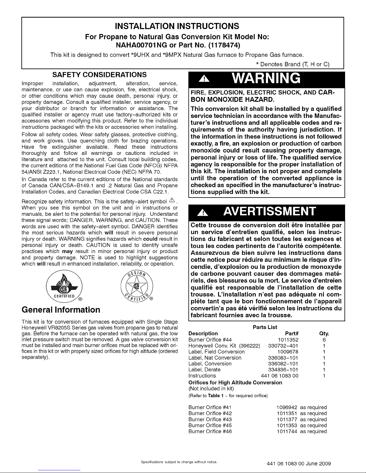
Disassembly
Refer to Figure 1 and the following steps.
1. After disconnecting power and gas supply to the furnace, re-
move the access door, exposing gas valve and burner
compartment.
2. Disconnect the yellow wire harness from the two terminals on
the Propane switch, the air pressure switch, and furnace har-
ness.
3. Reconnect yellow furnace harness wire to air pressure switch.
See furnace wiring label.
4. Disconnect gas line from fitting assembly so manifold assembly
can be removed.
5. Disconnect wiring at gas valve. Be sure to note the proper loca-
tion of any and all electrical wiring disconnected.
6. Remove the four (4) screws holding the manifold and gas valve
to the manifold supports. Do not discard any screws.
7. Carefully remove the manifold assembly and remove fitting as-
sembly from the gas valve.
8. Unscrew the Propane pressure switch from the bushing.
Figure 1 Disassembly
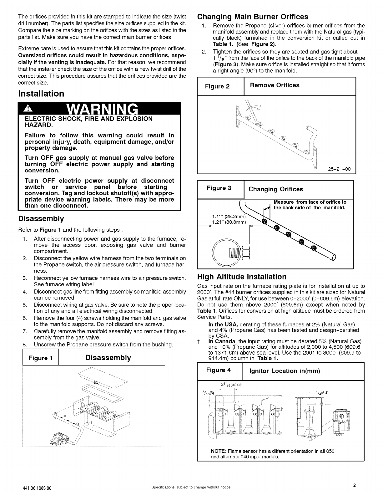
Changing Main Burner Orifices
1. Remove the Propane (silver) orifices burner orifices from the
manifold assembly and replace them with the Natural gas (typi-
cally black) furnished in the conversion kit or called out in
Table 1. (See Figure 2).
2. Tighten the orifices so they are seated and gas tight about
11/8" from the face of the orifice to the back of the manifold pipe
(Figure 3). Make sure orifice is installed straight so that it forms
a right angle (90 °) to the manifold.
Figure 2
Remove Orifices
25-21-00
Figure 3 Changing Orifices
I _ Measure fromface oforifice to
_ 4 the back side of the manifold.
1.11"(28.2mm) _',',',',',',',','_
__>1.21" (30.8mm) <_
High Altitude Installation
Gas input rate on the furnace rating plate is for installation at up to
2000'. The #44 burner orifices supplied in this kit are sized for Natural
Gas at full rate ONLY, for use between 0-2000' (0-609.6m) elevation.
Do not use them above 2000' (609.6m) except when noted by
Table 1. Orifices for conversion at high altitude must be ordered from
Service Parts.
In the USA, derating of these furnaces at 2% (Natural Gas)
and 4% (Propane Gas) has been tested and design-certified
by CSA.
1- In Canada, the input rating must be derated 5% (Natural Gas)
and 10% (Propane Gas) for altitudes of 2,000 to 4,500 (609.6
to 1371.6m) above sea level. Use the 2001 to 3000 (609.9 to
914.4m) column in Table 1.
..... ....... ....
44106 108300 Specifications subject to change without notice. 2
Figure 4 Ignitor Location in(mm)
21/16(52.39)
...... 1/4(6.4 )
A .
Y _',ii Jill
.....-_.i_.......
NOTE: Flame sensor has a different orientation in all 050
and alternate 040 input models.
Page 3

MANIFOLDPRESSUREANDORIFICESIZE
iii/iiiiiii'¸'ii
iiiiiiiiiiiiiiiiiiiiiiiiiiiiiiiiiiiiiiiiiiii
HEATING
VALUE
BTU/CU.
FT.
700
725
750
775
800
825
850
875
900
925
950
975
1000
1050
1100
* When installing the *9MPX 100,000 BTU furnace only, in downflow or horizontal positions, firing rate is reduced to 19,500 BTU/cell. Sub-
tract 0.2 in wc from the manifold pressures listed in table above for the correct manifold pressure.
Conversion:1inwc=249Pa
Bold- indicatesfactoryorificesize.
NOTE: Natural gas data is based on 0.60 specific gravity. For fuels with different specific gravity consult the National Fuel Gas Code ANSI
Z223.1-2006/N FPA 54-2006 or National Standard of Canada, Natural Gas And Propane Installation Code CSA B149.1-05.
In the USA, derating of these furnaces at 2% (Natural Gas) and 4% (Propane Gas) has been tested and design-certified by CSA.
t
In Canada, the inputratingmust be derated5% (NaturalGas)and 10% (PropaneGas)for altitudes of 2,000 to 4,500 (609.6 to
1371.6m) above sea level. Use the 2001 to 3000 (609.9 to 914.4m) column in Table 1.
Gas Valve Conversion Figure6
Conversion of Honeywell VR8205S Gas Valve using Natural Gas
Conversion Kit# 396222.
Figure 5 |Typical Gas Control Valve
INLET
Inlet
Pressure
Tap1/8NPT
1. Remove the regulator cap screw and pressure regulator adjust-
2. Remove the existing regulator spring from the regulator hous-
3. Insert the replacement spring (silver color) contained in this kit
4. Install the pressure regulator adjusting screw and give it six (6)
5. Replace the regulator cap screw.
6. Attach the Caution Label contained in the kit to the Gas Valve
NATURAL GAS MANIFOLD PRESSURE (in wc) 20,000 BTU per burner
MEANELEVATIONFEETABOVESEALEVELft (m)
0to 2000 2001to 30001 3001to 4000 4001to 5000 5001to6000
(0to610) (610.1to914)t (914.1to 1219) (1219.1to1524) (1524.1to1829)
Orifice Orifice Orifice Orifice Orifice
Mnfld Mnfld Mnfld Mnfld Mnfld
Press Press Press Press Press
6001to 7000
(1829.1to2134)
Orifice
Mnfld
Press
iiiiiii_!iiiii!!ii!iiii_iiii!i!!ii!iii!iiiiiiiiii!iiiiiiii;iiii_iii_i_ii;i_ii%iiiii!i!i!liii:i_!iii!£_iili!_i!iiii_liii!!iiiiii!i!i!liiiii!!!i£_i!iii!iii!i!i!iiiiiiiii;iiii_ii%i_iiiiiiii_ii_iiii:;iiiiii!i!iiii;ii!iX_i!@!i!ii!iilii_i!iiii!iiiii!i!i!iii!iiii!i!!_i_!iiiiiiii_i_ii_;iiiiliiiii!iiiiiii!!l_iii!iii!!i!iliii!!iiiiii!i!ii!liiiiiii@ii!iiiiii:iii!iii!_;_H_;_;_H__%_;_=_%;_J__%_;_ 44 3.7
44 3.7 44 3.4
44 3.5 44 3.2
.... 44 3.5 44 3.2 44 3.0
44 3.6 44 3.3 44 3.0 44 2.8
44 3.7 44 3.4 44 3.1 44 2.9 44 2.6
44 3.5 44 3.2 44 2.9 44 2.7 44 2.5
_-_i , !! .... 44 3.5 44 3.3 44 3.0 44 2.8 44 2.5 47 3.4
44 3.7 44 3.2 44 2.9 44 2.7 44 2.5 48 3.7 48 3.4
44 3.5 44 3.0 44 2.8 44 2.6 47 3.4 48 3.5 48 3.3
44 3.3 44 2.8 44 2.6 47 3.5 48 3.7 48 3.4 49 3.6
44 3.2 44 2.7 44 2.5 47 3.3 48 3.5 48 3.2 49 3.4
44 2.9 44 2.5 48 3.7 48 3.4 49 3.7 ........
46 3.3 48 3.7 48 3.4 49 3.7 ............
.... 44 3.3 44 3.1 44 2.8 44 2.6 47 3.5 48 3.6
Honeywell Gas Valve VR8205S
Color Propane Natural
Code Gas Gas
Pressure
Regulator
Adjusting
Screw
Spring Red
Black Black
.L
RegulatorAdjustment f
UnderCap
ing screw. (See Figure 5 and Figure 6)
ing.
into regulator housing.
Outlet
Pressure
Tap
1/8NpT
f_J--
OUTLET
@ ressureReg,AdjustScrew
Spring
Reassembly
Reassemble all parts in reverse order as removed. Attach Natural
Gas Conversion Label next to the furnace rating plate or to the front
exterior of the furnace. If Propane Gas Conversion Label is there
replace with Natural Conversion Label.
• Manifold Assembly - Be sure to engage the main burner ori-
fices in the proper openings in the burners.
• Verify the ignitor is in the correct location. (See Figure 4)
• Testing for leaks - After reassembly, turn the gas on and
check all joints for gas leaks using a soapy solution. All leaks
must be repaired immediately.
Gas Pressure
full turns. This will set the manifold pressure close to required
setting for normal operation.
where it can be readily seen. If Propane Conversion Label is al-
ready there, replace with new Natural Gas Caution Label.
• Gas input to burners MUST NOT exceed the rated input shown
on rating plate.
• Do NOT allow minimum gas supply pressure to vary down-
ward. Doing so will decrease input to furnace. Refer to Table 2
for gas supply and manifold pressures.
7001to 8000
(2134.1to 2438)
Orifice
Mnfld
Press
Stainless
Steel
3 Specifications subject to change without notice. 44106 108300
Page 4

Table 2 Gas Pressures - in wc (Pa)
Gas SupplyPressure
Type Recommended Max. Min.
Natural
7in wc 14in wc 4.5 inwc
(1744Pa) (3487 Pa) (1121Pa)
* See Table 1
Important Notes
Measured input can NOT exceed rated input.
Any major change in gas flow requires changing burner
orifice size.
Start-up and Check-out
1. Remove the plug from the Inlet Pressure Tap on gas valve and
install a manometer. (See Figure 5)
2. Open manual gas line valve to unit. Check for gas leaks and
correct as necessary. Check supply pressure, 7 in wc (1744Pa)
recommended, 4.5 in wc (1121Pa) minimum, 14 in wc (3487 Pa)
maximum. If not within these limitations DO NOT OPERATE
FURNACE, contact gas supplier.
3. Close manual gas line valve to unit, remove manometer and re-
place inlet pressure tap plug.
Gas Valve Adjustment
1. With the gas valve knob or switch in the OFF position, remove
the pressure tap plug from the outlet end of the valve, and con-
nect a "U" tube manometer to the pressure port. (Figure 5)
2. Turn the gas valve knob or switch to the ON position and restore
electrical power to unit. Cycle the main burner on and off sever-
al times to stabilize the pressure regulator diaphragm. This
MUST be done before an accurate pressure reading can be ob-
tained.
3. With the main burner on, read the manometer. For appropriate
reading see Table 1. Turn pressure regulator adjusting screw
clockwise to increase or counterclockwise to decrease man-
ifold pressure. Burner Input must not exceed nameplate rating.
Refer to Section "Checking Input Rate".
4. Turn gas valve to OFF. Remove the manometer and replace the
pressure tap plug and pressure regulator cap screw.
5. Start the main burners and check pressure tap plug for gas
leaks.
6. With gas valve on, observe furnace through two or more com-
plete cycles to be sure all controls are operating.
Checking Input Rate
Checking Burner Input Using A Meter To check the BTU input rate,
the test hand on the meter should be timed for at least one revolution
and the input determined from this timing. Refer to Section 11, Table
I1.1.1of the National Fuel Gas Code for converting test hand readings
to cubic feet per hour.
Example (BTUH)
NaturalGas No.of Time Per
BTU Contentper Seconds Cubic Foot in
cu.foot PerHour Seconds Hour
1,000 3,600 48 75,000
1,000x 3,600+ 48 = 75,000 BTUH
To Determine the appliance kW input rate from a .05m 3 test dial that
has been clocked at 80 seconds for one complete revolution.
Example (kW)
Number of
secondsper seconds per Sizeof test dial
hour complete (.05m3) kW m3/h
3,600 80 .05 2.25
44106 108300 Specifications subject to change without notice. 4
Number of
rotation
3,600+ 80x .05 = 7.2 m3/h
2.25m3/hx 10.35 kWh/m3 = 23.28 kW
23.28 x 3.412 = 79,431 BTU
Manifold
Pressure
3.5*
(872 Pa)
* Based on mid-range of elevation.
2001' - 3000" (609.9 - 914.4)1-
3001' - 4000" (914.7 - 1219.2)
4001' - 5000" (1219.5 - 1524)
5001' - 6000" (1524.3 - 1828.8)
6001' - 7000" (1829.1 - 2133.6)
7001' - 8000" (2133.9 - 2438.4)
In the USA, derating of these furnaces at 2% (Natural Gas) and
4% (Propane Gas) has been tested and design-certified by
CSA.
1- In Canada, the inputrating must be derated 5% (Natural Gas)
and 10% (Propane Gas) for altitudes of 2,000 to 4,500 (609.6
to1371.6m) above sea level. Use the 2001 to 3000 (609.9 to
914.4m) column in Table 1.
Main Burner Flame Check
Allow the furnace to run approximately 10 minutes then inspect the
main burner and pilot flames. Check for the following: (See Figure 7)
• Stable and blue flames. Dust may cause orange tips or wisps of
yellow, but flames MUST NOT have solid, yellow tips.
• Flames extending directly from burner into heat exchanger.
• Flames do NOT touch sides of heat exchanger
If any problems with main burner flames are noted, it may be neces-
sary to adjust gas pressures or check for drafts.
Figure 7 JMain Burner
High Altitude Derated Unit Label
The derated label supplied with the conversion kit must be completed
and affixed to the furnace near the rating plate. Fill in the manifold
pressure, orifice size and revised input rate.
Refer toTable 1 provided to determine the proper orifice part numbers
for ordering purposes.
Verify System Operation
Upon completion of all conversion procedures, perform the following
BTU Per
International Comfort Products, LLC
Lewisburg, TN 37091 U.S.A.
steps to attach appropriate labels and verify the system operation.
1. Locate the Natural Gas Conversion Label next to the furnace
rating plate. Replace Propane Gas Conversion Label ifthere.
2. Fill out and attach the Field Conversion Label to the front exteri-
or of the furnace. Replace any existing Field Conversion Label.
3. Turn the thermostat to itslowest temperature setting or to OFF if
equipped with a System Select Switch.
4. Turn the gas valve control knob or switch to ON.
5. Reinstall all access panels.
6. Turn ON all electrical power to the unit.
7. Set the thermostat to the desired temperature and the System
Select Switch to HEAT.
8. Observe unit operation through two complete heating cycles. See
"Sequence of Operation" in furnace installation instructions.
*High Altitude Input Rate =
Nameplate Sea Level Input Rate x (Multiplier)
HighAltitude
Elevation Multiplier
NaturalGas*StandardInput
0'- 2000' (0 - 609.6)
1.00
0.95
0.93
0.91
0.89
0.87
0.85
Burner
10-10-78
 Loading...