

Page 1
INSTALLATION INSTRUCTIONS
For Natural Gas to Propane Conversion Kit Model No:
NAHA00701LP or Part No. (1178473)
This kit is designed to convert *9UHX and *9MPX Natural Gas furnace to Propane Gas furnace.
SAFETY CONSIDERATIONS
Improper installation, adjustment, alteration, service,
maintenance, or use can cause explosion, fire, electrical shock,
or other conditions which may cause death, personal injury, or
property damage. Consult a qualified installer, service agency, or
your distributor or branch for information or assistance. The
qualified installer or agency must use factory-authorized kits or
accessories when modifying this product. Refer to the individual
instructions packaged with the kits or accessories when installing.
Follow all safety codes. Wear safety glasses, protective clothing,
and work gloves. Use quenching cloth for brazing operations.
Have fire extinguisher available. Read these instructions
thoroughly and follow all warnings or cautions included in
literature and attached to the unit. Consult local building codes,
the current editions of the National Fuel Gas Code (NFCG) NFPA
54/ANSI Z223.1, National Electrical Code (NEC) NFPA 70.
In Canada refer to the current editions of the National standards
of Canada CAN/CSA-B149.1 and .2 Natural Gas and Propane
Installation Codes, and Canadian Electrical Code CSA C22.1.
Recognize safety information. This is the safety-alert symbol /_ .
When you see this symbol on the unit and in instructions or
manuals, be alert to the potential for personal injury. Understand
these signal words; DANGER, WARNING, and CAUTION. These
words are used with the safety-alert symbol. DANGER identifies
the most serious hazards which will result in severe personal
injury or death. WARNING signifies hazards which could result in
personal injury or death. CAUTION is used to identify unsafe
practices which may result in minor personal injury or product
and property damage. NOTE is used to highlight suggestions
which will result in enhanced installation, reliability, or operation.
General Information
This kit is for conversion of furnaces equipped with Honeywell VR8205S
Series single stage gas valves certified for use with Natural Gas (and so
marked) to units functionally the same as the certified furnace for use
with Propane Gas, Before the furnace can be operated with Propane
Gas, the low pressure switch must be installed. A gas valve conversion
kit must be installed and main burner orifices must be replaced with ori-
fices in this kit or with properly sized orifices for high altitude (or-
dered separately),
* Denotes Brand (T, H or C)
FIRE, EXPLOSION, ELECTRIC SHOCK, AND CAR-
BON MONOXIDE HAZARD.
This conversion kit shall be installed by a qualified
service technician in accordance with the Manufac-
turer's instructions and all applicable codes and re-
quirements of the authority having jurisdiction. If
the information in these instructions is not followed
exactly, a fire, an explosion or production of carbon
monoxide could result causing property damage,
personal injury or loss of life. The qualified service
agency is responsible for the proper installation of
this kit. The installation is not proper and complete
until the operation of the converted appliance is
checked as specified in the manufacturer's instruc-
tions supplied with the kit.
Cette trousse de conversion dolt 6tre install6e par
un service d'entretien qualifie, selon les instruc-
tions du fabricant et selon toutes les exigences et
tous les codes pertinents de rautorite competente.
Assurezvous de bien suivre les instructions dans
cette notice pour r6duire au minimum le risque d'in-
cendie, d'explosion ou la production de monoxyde
de carbone pouvant causer des dommages mate-
riels, des blessures ou la mort. Le service d'entreien
qualifi6 est responsable de rinstallation de cette
trousse. L'installation n'est pas ad6quate ni com-
pl6te tant que le bon fonctionnement de rappareil
convertin'a pas 6te verifi6 selon les instructions du
fabricant fournies avec la trousse.
This conversion kit shall be installed by a qualified service agency.
Please read these instructionscompletely before attempting instal-
lation. Consult gas supplier and tables in National Fuel Gas Code
NFPA 54/ANSI Z223.1, 2006 or latest edition. In Canada, the Na-
tional Standard CAN/CGA B149-1 and B149-2.
Parts List
Description Part# Qty,
Burner Orifice #55 1011354 6
Honeywell Conv. Kit (396221) 330733-401 1
Switch, Low Pressure(LGPS) 1008801 1
Fitting Asy. 1009775 1
Wire Asy. 1173071 1
Label, Field Conversion 1009678 1
Label, Propane Conversion 332874-101 1
Label, Derate 334836-101 1
Label, Conversion 336084-101 1
Label, Conversion 336085-101 1
Instructions 441 06 1082 00 1
Orifices for High Altitude Conversion (Not included in kit)
(Referto Table 1- for required orifice)
Burner Orifice #56 1011355 as required
Specifications subject to change without notice.
441 06 1082 00 June 2009
Page 2
The orifices provided in this kit are stamped to indicate the size (twist
drill number) and are sized for commercially pure propane gas
ONLY. DO NOT use them with butane or a mixture of butane and
propane gas. The parts list specifies the size orifices supplied in the
kit. Compare the size marking on the orifices with the sizes as listed
in the parts list. Make sure you have the correct main burner orifices.
Extreme care is used to assure that this kit contains the proper
orifices. Oversized orifices could result in hazardous
conditions, especially if the venting is inadequate. For that
reason, we recommend that the installer check the size of the orifice
with a new twist drill of the correct size. This procedure assures that
the orifices provided are the correct size.
Installation
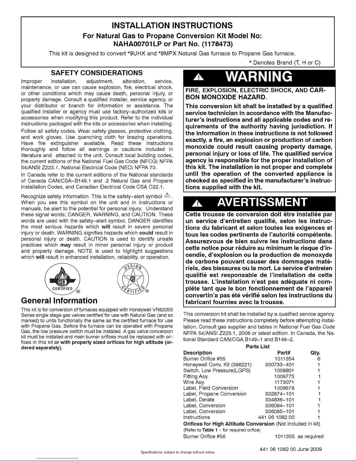
2.
Tighten the orifices so they are seated and gas fight about 11/8"
(28.6mm) from the face ofthe orifice to the back ofthe manifold
pipe (Figure 2). Make sure orifice is installed straight so that it
forms a right angle (90°) to the manifold.
Figure 2 JRemove Orifices
ELECTRIC SHOCK, FIRE AND EXPLOSION
HAZARD.
Failure to follow this warning could result in
personal injury, death, equipment damage, and/or
property damage.
Turn OFF gas supply at manual gas valve before
turning OFF electric power supply and starting
conversion.
Turn OFF electric power supply at disconnect
switch or service panel before starting
conversion. Tag and lockout shutoff(s) with appro-
priate device warning labels. There may be more
than one disconnect.
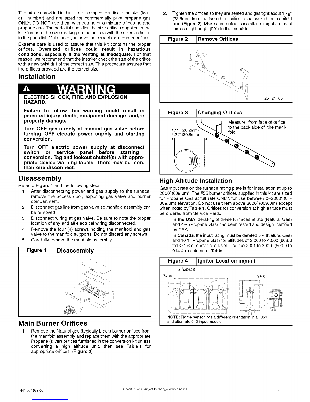
Disassembly
Refer to Figure 1 and the following steps.
1. After disconnecting power and gas supply to the furnace,
remove the access door, exposing gas valve and burner
compartment.
2. Disconnect gas line from gas valve so manifold assembly can
be removed.
3. Disconnect wiring at gas valve. Be sure to note the proper
location of any and all electrical wiring disconnected.
4. Remove the four (4) screws holding the manifold and gas
valve to the manifold supports. Do not discard any screws.
5. Carefully remove the manifold assembly.
Figure 1
Disassembly
25-21-00
Figure 3
I .t1" (28.2mm)_
1.2t" (30.8ram)
J Changing Orifices
Measure from face of orifice
to the back side of the mani-
fold.
High Altitude Installation
Gas input rate on the furnace rating plate is for installation at up to
2000' (609.6m). The #55 burner orifices supplied in this kit are sized
for Propane Gas at full rate ONLY, for use between 0-2000' (0 -
609.6m) elevation. Do not use them above 2000' (609.6m) except
when noted by Table 1. Orifices for conversion at high altitude must
be ordered from Service Parts.
In the USA, derating of these furnaces at 2% (Natural Gas)
and 4% (Propane Gas) has been tested and design-certified
by CSA.
1- In Canada, the input rating must be derated 5% (Natural Gas)
and 10% (Propane Gas) for altitudes of 2,000 to 4,500 (609.6
to1371.6m) above sea level. Use the 2001 to 3000 (609.9 to
914.4m) column in Table 1.
Main Burner Orifices
Remove the Natural gas (typically black) burner orifices from
the manifold assembly and replace them with the appropriate
Propane (silver) orifices furnished in the conversion kit unless
converting a high altitude unit, then see Table 1 for
appropriate orifices. (Figure 2)
44106 1082 00 Specifications subject to change without notice. 2
Figure 4 J lgnitor Location in(mm)
21/16( 52. 39)
5/1o/8)_
i..............................;_ _,- ::o
t
\-- .....................................................................................................................................i
NOTE: Flame sensor has a different orientation in all 050
and alternate 040 input model&
Page 3

MANIFOLD PRESSUREAND ORIFICE SIZE
Table 1 PROPANE GAS MANIFOLD PRESSURE (in wc) 20,000 BTUH per burner
HEATING FURNACE MEANELEVATIONFEETABOVESEALEVELft (m)
VALUE
BTU/CU.
FT. BURNER (0to 610) (610.1to914)1" (914.1to1219) (1219.1to1524) (1524.1to1829) (1829.1to2134) (2134.1to2438)
2500 10.0 8.9 8.4 10.0 10.0 10.0 10.0
OrificeSize 20000
2500 9.9 8.4 8.0 10.0 10.0 10.0 9.6
OrificeSize 19500_ #55 #55 #55 i #5_ i, i #5_ i ....
$ Applies to *9MPX 100,000 BTU models only, when installed in the downflow or horizontal applications
Conversion:1inwc=249Pa
NOTE: Propane data is based on 1.53 specific gravity. For fuels with different specific gravity consult the National Fuel Gas Code ANSI
Z223.1-2006/N FPA 54-2006 or National Standard of Canada, Natural Gas and Propane Installation Code CSA B149.1-05.
In the USA, derating of these furnaces at 2% (Natural Gas) and 4% (Propane Gas) has been tested and design-certified by CSA.
1- In Canada, the input rating must be derated 5% (Natural Gas) and 10% (Propane Gas) for altitudes of 2,000 to 4,500 (609.6 to
1371.6m) above sea level. Use the 2001 to 3000 (609.9 to 914.4m) column in and Table 1.
INPUTBTU/ 0 to 2000 2001to30001" 3001to 4000 4001to5000 5001to 6000 6001to 7000 7001to 8000
55 ....
Gas Valve Conversion Figure 6 Honeywell Gas Valve VR8205S
Conversion of Honeywell VR8205S Gas Valve using Propane Gas
Conversion Kit # 396221. _ PressureReg.Adjust Color Propane Natural
1. Remove the cap screw and pressure regulator adjusting _9 sc,ew Code Gas Gas
screw. (See Figure 5 or Figure 6) spring Pressure
2. Remove the existing regulator spring from the regulator
housing. Regulator Black Black
3. Insert the replacement spring (red color) contained in this kit Adjusting
into regulator housing. Screw
4. Install the pressure regulator adjusting screw and give it Stainless
eleven full clockwise turns. This will set the manifold pressure Spring Red
close to required setting for normal operation. Steel
5. Replace the regulator cap screw. Propane Low Pressure Switch (Required)
6. Attach the Yellow Attention Label contained in the kit to the 1. Using pipe joint compound that is resistant to Propane gas,
Gas Valve where it can be readily seen. tighten the fitting assembly into the inlet side of the gas valve.
Figure 5 ] Typical Gas Control Valve (Figure 7). Position fitting assembly as shown.
UnderRegulat°rcapAdjustment "_ _'_ _ pipe dope on connection. Tighten securely.
:;_ Tap 3. Remove one yellow wire from the air pressure switch.
INLET _ _ ,_-_,, _' wire in the wire harness provided.
.... z .,mr. OUTLET termination on the air pressure switch.
Inlet ,>i, 5. Connect the other end of the wire harness to the two terminals
Pressure _ on the Propane switch.
Tap1/8NPT Note: Propane switch is factory set to open if Propane gas supply
Figure 7 ] Typical Gas Piping and Adding Propane Low Pressure Switch
................ --_ Manualshut-off Right pipe
_ \-. valve ;' entry
...._ // DripLeg ,,
Switch Left pipe / ,
Detail -_.... entry _..._ " , ,'/
I _ ___ J Connect this wire to the male terminal of the insulated yellow
i _ 4. Connect the other yellow wire in the harness to the open
, _ pressure falls below 6 in wc (1495 Pa).
"_a Outlet Note: Do not block inlet port of pressure switch with pipe dope.
Pressure Switch will not operate if inlet port is blocked.
1/8NPT
.... _ 1"(25.4mm).
&Union# .....,
2. Screw the Propane pressure switch into the bushing. Use
Note: See Furnace Wiring Label, to confirm wiring.
f -- ........
..................._ cl
# Union should be outside cabinet except pipingwhenusingrightsidegas
when clearances disallow, then it may be z pipeentry.
installed inside the cabinet. ;
Manualshut-offvalveMUSTbeupstreamofdripleg, //"
union,andfurnace, ;;
3 Specifications subject to change without notice. 44106 108200
Alternative ----
installation
Useelbowsand1" (25.4mm)
close nippletoconnectvalveto
/
Page 4

Reassembly
Reassemble all parts in reverse order as removed. Attach Propane
Conversion Label next to the furnace rating plate or to the front exteriorof
the furnace.
• Manifold Assembly - Be sure to engage the main burner
orifices in the proper openings in the burners.
• Verify the ignitor is inthe correct location. (See Figure 4)
• Testing for leaks - After reassembly, turn the gas on and
check all joints for gas leaks using a soapy solution. All leaks
must be repaired immediately.
Gas Pressure
• Refer to the furnace rating plate for the approved gas input
rating.
• Gas input to burners MUST NOT exceed the rated input
shown on rating plate.
• Do NOT allow minimum gas supply pressure to vary
downward. Doing so wilt decrease input to furnace. Refer to
Table2 for gas supply and manifold pressures.
Table 2 Gas Pressures - in wc(Pa)
Gas Supply Pressure
Type Recommended Max. Min.
Propane 11 (2740) 14 (3487) 11 (2740) 10 (2490) *
* See Table 1
Important Notes
,, With Propane gas, the rated input is obtained when the BTU
content is 2,500 BTU per cubic foot and manifold pressure
set at 10 in w¢ (2490 Pa),
. If Propane gas has a different BTU content, orifices MUST be
changed by licensed Propane installer.
. Measured input can NOT exceed rated input.
. Any major change in gas flow requires changing burner
orifice size.
Start-up and Check-out
1. Remove the plug from the Inlet Pressure Tap on gas valve
and install a manometer. (Figure 5)
2. Open manual gas line valve to unit. Check for gas leaks and
correct as necessary. Check supply pressure, 11 in wc
recommended (2740 Pa), 11 in wc (2740 Pa ) - minimum, 14
in wc (3487 Pa) - maximum. If not within these limitations DO
NOT OPERATE FURNACE, contact gas supplier.
3. Close manual gas line valve to unit, remove manometer and
replace inlet pressure tap plug.
Gas Valve Adjustment
1. With the gas valve knob or switch in the OFF position, remove
the pressure tap plug from the outlet end of the valve, and
connect a "U" tube manometer to the pressure port. (See
Figure 5)
2. Turn the gas valve knob or switch to the ON position and
restore electrical power to unit. Cycle the main burner on and
off several times to stabilize the pressure regulator
diaphragm. This MUST be done before an accurate pressure
reading can be obtained.
3. With the main burner on, read the manometer. For
appropriate reading see Table 1. Turn pressure regulator
adjusting screw clockwise to increase or counterclockwise to
decrease manifold pressure. Burner Input must not exceed
nameplate rating. Refer to Section "Checking Input Rate".
4. Turn gas valve to OFF. Remove the manometer and replace
the pressure tap plug and pressure regulator cap screw.
5. Start the main burners and check pressure tap plug for gas
leaks.
6. With gas valve on, observe furnace through two or more
complete cycles to be sure all controls are operating.
44106 108200
Checking Input Rate
Nameplate Sea Level Input Rate x (Multiplier)
0 - 2000' (0 - 608)
2001'- 3000' (609.9 - 914.4) t
3001' - 4000' (914.7 - 1219.2)
4001' - 5000" (1219.5 - 1524)
5001' - 6000" (1524.3 - 1828.8)
6001' - 7000" (1829.1 - 2133.6)
7001' - 8000" (2133.9 - 2438.4)
* Based on mid-range of elevation.
In the USA, derating of these furnaces at 2% (Natural Gas)
and 4% (Propane Gas) has been tested and design-certified
by CSA.
t In Canada, the input rating must be derated 5% (Natural Gas)
and 10% (Propane Gas) for altitudes of 2,000 to 4,500 (609.6
to1371.6m) above sea level. Use the 2001 to 3000 (609.9 to
914.4m) column in Table 1.
Main Burner Flame Check
Manifold
Pressure
Check for the following: (See Figure 8)
• Stable and blue flames. Dust may cause orange tips or wisps
of yellow, but flames MUST NOT have solid, yellow tips.
• Flames extending directly from burner into heat exchanger.
• Flames do NOT touch sides of heat exchanger
If any problems with main burner flames are noted, it may be
necessary to adjust gas pressures or check for drafts.
Figure 8 J Main Burner
High Altitude Derated Unit Label
The derated label supplied with the conversion kit must be
completed and affixed to the furnace near the rating plate. Fill in the
manifold pressure, orifice size and revised input rate.
Refer to Table 1 provided to determine the proper orifice part
numbers for ordering purposes.
Verify System Operation
Upon completion of all conversion procedures, perform the
following steps to attach the appropriate labels and verify the system
operation.
1. Locate the Propane Conversion Label next to the furnace
rating plate.
2. Fill out and attach the Field Conversion Label near the
furnace rating plate or to the front exterior of the furnace.
3. Turn the thermostat to its lowest temperature setting or to
OFF if equipped with a System Select Switch.
4. Turn the gas valve control knob or switch to ON.
5. Reinstall all access panels.
6. Turn ON all electrical power to the unit.
7. Set the thermostat to the desired temperature and the
System Select Switch to HEAT.
8. Observe unit operation through two complete heating cycles.
See "Sequence of Operation" in furnace installation
instructions.
InternationalComfort Products,LLC
Lewisburg,TN 37091 U.S.A.
Specifications subject to change without notice.
*High Altitude Input Rate =
Elevation
ft (m)
Burner Face
High Altitude Multiplier
Propane Gas*
1.00
0.90
0.86
0.82
0.78
0.74
0.70
10-10-78
 Loading...