

Page 1
INSTALLATION INSTRUCTIONS
TWINNING KIT
NAHA00601WK
Please read these instructions completely before starting the
installation.
SAFETY CONSIDERATIONS
! WARNING
FIRE, EXPLOSION, ELECTRICAL SHOCK AND CARBON
MONOXIDE POISONING HAZARD
Failure to follow this warning could result in personal injury,
death and/or property damage.
Improper installation, adjustment, alteration, service,
maintenance, or use can cause carbon monoxide poisoning,
explosion, fire, electrical shock, other conditions, which could
result in personal injury or death. Consult a qualified service
agency, local gas supplier, or your distributor or branch for
information or assistance. The qualified service agency must
use only factory−authorized kits or accessories when
modifying this product.
!
FIRE, EXPLOSION, ELECTRICAL SHOCK, AND CARBON
MONOXIDE POISONING HAZARD
Failure to follow this warning could result in dangerous
operation, personal injury, death, or property damage.
Furnaces shall NOT be twinned (i.e. tandem or staged
operation) unless approved in factory technical specifications
literature for the furnace. A factory authorized, field−supplied
Twinning Kit MUST be used. Consult furnace pre−sale
literature for specific models approved for twinning and the
correct twinning kit. Twinned furnaces must be installed on
both a common supply AND a common return duct system
as shown in the Twinning Kit Installation Instructions. Only
two furnaces can be twinned on a common supply and
return duct system using a factory authorized twinning kit.
WARNING
gloves. Have a fire extinguisher available during start−up,
adjustment steps, and service calls.
Recognize safety information. This is the safety−alert symbol
. When you see this symbol on the unit and in instructions or
manuals, be alert to the potential for personal injury.
Understand the signal words DANGER, WARNING, and
CAUTION. These words are used with the safety−alert symbol.
DANGER identifies the most serious hazards which will result
in severe personal injury or death. WARNING signifies hazards
which could result in personal injury or death. CAUTION is
used to identify unsafe practices which may result in minor
personal injury or product and property damage. NOTE is used
to highlight suggestions which will result in enhanced
installation, reliability, or operation.
TABLE OF CONTENTS
SAFETY CONSIDERATIONS 1................................
TABLE OF CONTENTS 1.....................................
INTRODUCTION 2..........................................
DESCRIPTION AND USAGE 2................................
ELECTROSTATIC DISCHARGE (ESD) PRECAUTION 4..........
MULTIPOISE SINGLE−SPEED AND TWO−SPEED
NON−CONDENSING HSI FURNACE MODELS 4................
INSTALL FURNACES 5......................................
DIMENSIONS 5.............................................
CONNECT ELECTRICAL COMPONENTS—HEATING 11..........
CONNECT ELECTRICAL COMPONENTS−COOLING 15..........
VENTING 15................................................
GAS SUPPLY PIPING 15......................................
ELECTRICAL SUPPLY CONNECTIONS 15......................
START−UP AND ADJUSTMENT 16.............................
SEQUENCE OF OPERATION 19...............................
Installing and servicing heating equipment can be hazardous
due to gas and electrical components. Only trained and
qualified personnel should install, repair, or service
heating equipment. Untrained personnel can perform basic
maintenance functions such as cleaning and replacing air
filters. All other operations must be performed by trained
service personnel. When working on heating equipment,
observe precautions in literature, on tags, and on labels
attached to or shipped with unit and other safety precautions
that may apply.
These instructions cover the minimum requirements and
conform to existing national standards and safety codes. In
some instances, these instructions exceed certain local codes
and ordinances, especially those that may not have kept up
with changing residential construction practices. We require
these instructions as a minimum for a safe installation.
Follow all safety codes. In the United States, follow all safety
codes including the current edition of the National Fuel Gas
Code (NFGC) NFPA No. 54/ANSI Z223.1. In Canada, refer to
the current edition of the National Standard of Canada, Natural
Gas and Propane Installation Codes (NSCNGPIC),
CAN/CSA−B149.1 and .2. Wear safety glasses and work
! WARNING
ELECTRICAL SHOCK AND FIRE HAZARD
Failure to follow this warning could result in personal injury,
death, and/or property damage.
Turn off the gas and electrical supplies to the furnace and
install lockout tag before performing any installation or
modification. Follow the operating instructions on the label
attached to the furnace.
!
CAUTION
CUT HAZARD
Failure to follow this caution may result in personal injury.
Sheet metal parts may have sharp edges or burrs. Use
care and wear appropriate protective clothing and gloves
when handling parts.
443 06 2403 01 6/12/2018
Page 2
INTRODUCTION
IMPORTANT: Only the furnace sizes listed in Table 2 can be
twinned. Both furnaces must have the same product number,
including heating and cooling sizes, to achieve correct
operation.
This furnace twinning kit permits connection to the following
furnaces to operate as a single unit on the same duct work:
S Two multipoise, 33.3 inch (846 mm), single−speed,
non−condensing furnaces (See Figure 1, Figure 2 and
Table 2)
S Two multipoise, 33.3 inch (846 mm), two−stage,
non−condensing furnaces (See Figure 1, Figure 14, and
Table 2)
!
UNIT AND PROPERTY DAMAGE HAZARD
Failure to follow this warning could result in unit and
property damage.
A non−condensing furnace shall NOT be twinned with a
condensing furnace. Two−stage condensing or
non−condensing furnaces shall not be twinned with any
single stage furnace. Do not twin furnaces that have a
different number of blower motor speed taps together.
Furnaces shall only be twinned in the positions shown.
Variable−speed furnaces shall not be twinned.
WARNING
DESCRIPTION AND USAGE
Refer to the appropriate section for your furnaces.
SECTION I: Models N8MSN & N8MSL Multipoise
Single−Speed Non−Condensing HSI Furnaces
S Single−Stage Heat with Single−Stage Gas−Heat Thermostat
S Two−Stage Heat with Two−stage Gas−Heat Thermostat
Models F8MTL & G8MTL Multipoise Two−Stage
Non−Condensing HSI Furnaces
S Two−Stage Heat with Single−Stage Gas−Heat Thermostat
S Two−Stage Heat with Two−Stage Gas−Heat Thermostat
DUCT CONNECTIONS
All furnaces must have a common supply plenum attached to
the furnaces or evaporator coils prior to any branch supply
trunk or take−off. The height of the plenum should be at least
as high (upflow/downflow) or as long (horizontal) as the width
of one furnace. Supply air dampers, when used should be
installed in the branch ducts, not in the common plenum. Fire
or smoke dampers, when required by code may be installed in
the common plenum. Refer to the damper manufacturer’s
ratings installation instructions for proper application. The
damper should not create undue restriction in the open
position.
All furnaces must be installed to ensure sufficient return air to
both furnaces:
S For upflow furnaces: A combination of one full side of each
and bottom inlet plenum or bottom only inlet plenum shall be
used for return air to each furnace. The preferred method is
to have all return air brought into the bottom of the furnaces
through a common bottom plenum. The bottom return−air
plenum shall be at least as high as the width of the furnace
bottom return−air opening. When there are height limitations,
the bottom return−air plenum height can be reduced to 8 in.
minimum (203mm) if one entire side return−air opening of
each furnace is used in conjunction with the bottom return
opening. Rear inlet plenums shall not be used. (See
Figure 1) Connect all return trunks or branch return ducts to
common return plenum.
S For downflow and horizontal furnaces: All return air must
be brought into the bottom opening of the furnace through a
common return air plenum. The return−air plenum shall be at
least as long (horizontal) or tall (downflow) as the width of
the furnace return−air opening. (See Figure 2) Connect all
return trunks or branch return ducts to common return
plenum.
S For all furnaces: Fire or smoke dampers, when required by
code may be installed in the common return plenum. Refer
to the damper manufacturer’s ratings installation instructions
for proper application. The damper should not create undue
restriction in the open position.
!
FIRE HAZARD
Failure to follow this warning could result in improper
auxiliary limit operation, fire, personal injury or death.
Do not remove the center return−air partitions between
the furnaces.
Staged heating operation is permitted only with this twinning
kit. With the single−speed, non−condensing furnaces, the
left−hand furnace is used for first−stage heat, and both
furnaces are used for second−stage heat. With the two−stage,
non−condensing furnaces, low−gas heat in both furnaces is
used for first−stage heat, and high−gas heat in both furnaces is
used for second−stage heat. This kit ensures both furnace
blowers operate simultaneously so air flows through the duct
work rather than recirculating in a loop between the furnaces.
WARNING
2
Specifications subject to change without notice.
443 06 2403 01
Page 3
Common
A
Supply Air
Plenum
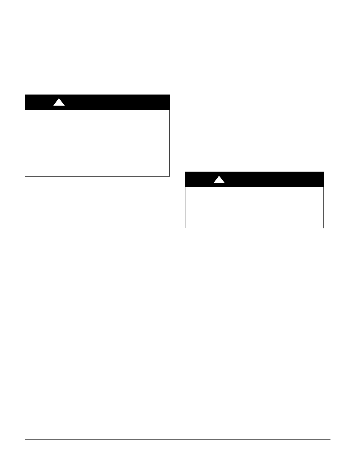
Figure 1 − Upflow Ductwork Connections
Common
A
Supply Air
Plenum
Twinned Furnace
Common
Return
A
A
Example 1
Example 1 Notes:
Return duct cannot obstruct access to either furnace
Return Air can enter thru any combination of:
a. Left side only
b. Right side only
c. Bottom only
d. Back of platform when height of platform
equal Dimension A as shown
e. Any combination of a, b, c, d
Air
Plenum
Figure 2 − Downflow/Horizontal Ductwork Connections
Return
Air
Plenum
B
Example 2 Notes:
When furnaces are installed Back-to-Back (not shown)
return duct MUST connect to the common return plenum
and side inlet of BOTH furnaces
Return duct cannot obstruct access to either furnace
Twinned Furnace
8 MIN
Common Return
Air Plenum
Example 2
Return
Air
Plenum
B
A02223
Common
Return
Air
Plenum
A
A
Twinned Furnaces
Common
Supply Air
Plenum
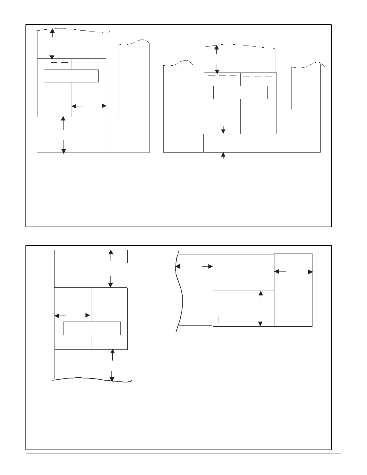
Example 3 - Downflow Applications
Example 3 Notes:
Do not connect return air to any side of the
furnace
Connect return air plenum as shown
A
A
Common
Supply Air
Plenum
Example 4 Notes:
Do not connect return air to any side of furnace.
Do not stack condensing furnaces of top of each other
When furnaces are installed Side-by-Side (not shown),
return connection is similiar. Depth of plenum
Dimension A must equal to the front width of one furnace
Twinned furnaces
Stacked* (80% ONLY)
A
Example 4 - Horizonal Applications
A
Common
Return
Air
Plenum
443 06 2403 01
Specifications subject to change without notice.
3
Page 4
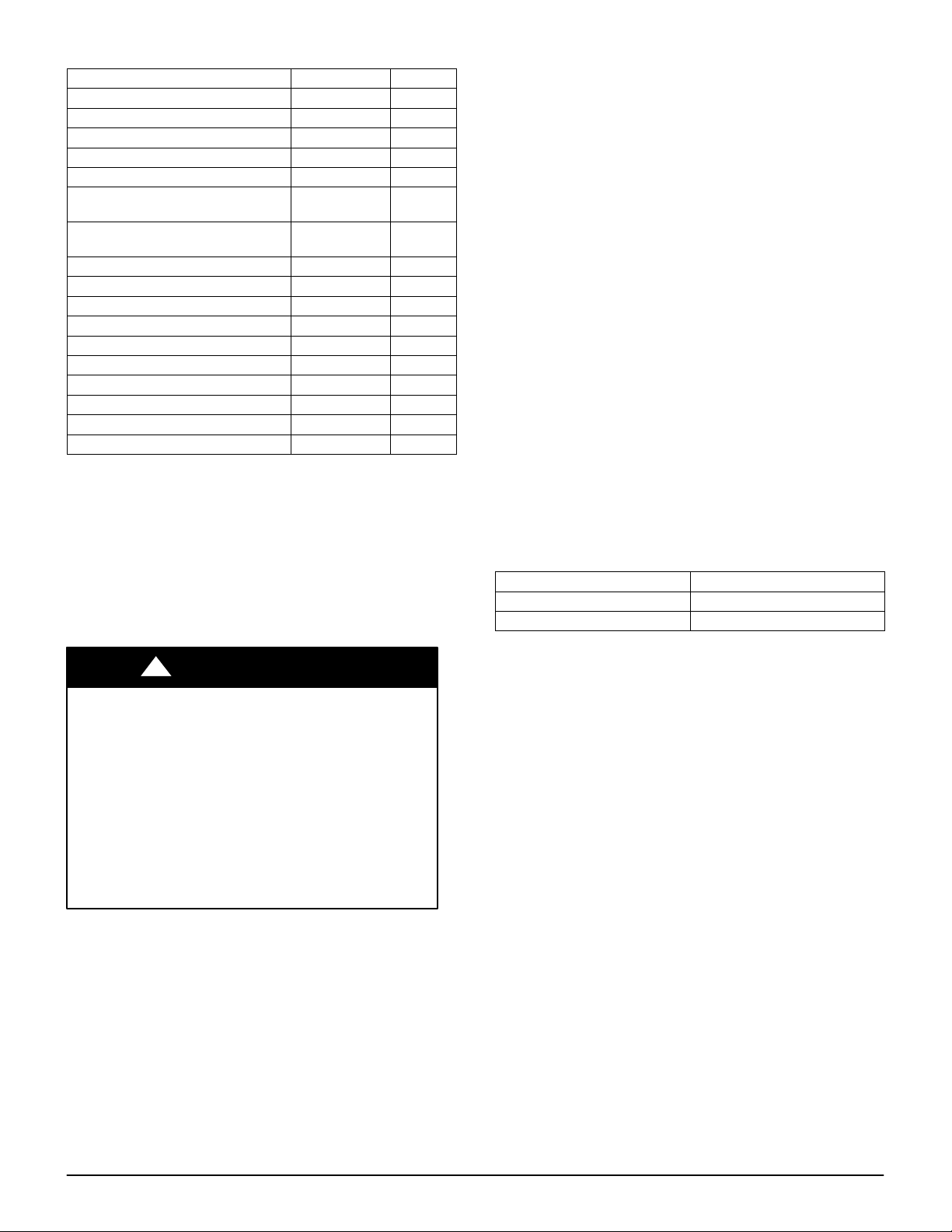
Table 1 – Kit Contents
DESCRIPTION PART NO. QTY
Sealing tape 2
External extension harness 327962701 1
Main twinning harness 327957701 1
Secondary twinning harness 327959701 1
Twostage furnace wiring diagram 337068101 1
Single stage furnace heat wiring
diagram
Single stage furnace/twostage
heat wiring diagram
Label 327956101 1
Tape 1
Bag Assembly includes:
Snap bushing 2
Screws (HEX HD 6B X ¾) 10
Screws (flat head) 1
Wire tie 4
Clamps 2
Installation Instructions 1
Auxiliary door switch bracket 1
337070101 1
337069101 1
NOTE: As a result of staged heating with single−speed
furnaces, the air temperature distribution in the supply plenum
may be uneven when only 1 furnace is heating.
NOTE: Refer to the Installation, Start−Up, and Operating
Instructions supplied with each furnace for information on
venting, clearances, start−up, maintenance, and other
information not covered in this publication.
See Table 1 for kit contents.
ELECTROSTATIC DISCHARGE (ESD) PRECAUTION
!
UNIT DAMAGE HAZARD
Failure to follow this caution may result in unit and
component damage.
Failure to follow this caution could result in unit and
component damage. Electrostatic discharge can affect
electronic components. Take precautions during furnace
installation and servicing to protect the furnace
electronic control. Precautions will prevent electrostatic
discharges from personnel and hand tools which are
held during the procedure. These precautions will help
to avoid exposing the control to electrostatic discharge
by putting the furnace, the control, and the person at the
same electrostatic potential.
CAUTION
A02224
1. Disconnect all power to the furnace. DO NOT TOUCH
THE CONTROL OR ANY WIRE CONNECTED TO THE
CONTROL PRIOR TO DISCHARGING YOUR BODY’S
ELECTROSTATIC CHARGE TO GROUND.
2. Firmly touch a clean, unpainted, metal surface of the
furnace chassis which is close to the control. Tools held
in a person’s hand during grounding will be satisfactorily
discharged.
3. After touching the chassis you may proceed to service
the control or connecting wires as long as you do
nothing that recharges your body with static electricity
(for example; DO NOT move or shuffle your feet, DO
NOT touch ungrounded objects, etc.).
4. If you touch ungrounded objects (recharge your body
with static electricity), firmly touch furnace again before
touching control or wires.
5. Use this procedure for installed and uninstalled
(ungrounded) furnaces.
6. Before removing a new control from its container,
discharge your body’s electrostatic charge to ground to
protect the control from damage. If the control is to be
installed in a furnace, follow items 1 through 5 before
bringing the control or yourself into contact with the
furnace. Put all used AND new controls into containers
before touching ungrounded objects.
7. An ESD service kit (available from commercial sources)
may also be used to prevent ESD damage.
SECTION I: MULTIPOISE SINGLE−SPEED AND
TWO−SPEED NON−CONDENSING HSI FURNACE
MODELS
SINGLE−STAGE TWO−STAGE
N8MSN F8MTL
N8MSL G8MTL
NOTE: Throughout these instructions, when the furnace
installed side−by−side, the left−hand (LH) side will be referred
to as the LH furnace, and the furnace installed on the
right−hand (RH) side as the RH furnace. When the furnaces
are installed back−to−back, the left−hand (LH) side will be
referred to as the LH furnace, and the furnace installed on the
right−hand (RH) side as the RH furnace when viewed from the
side with the extension harness installed.
4
Specifications subject to change without notice.
443 06 2403 01
Page 5
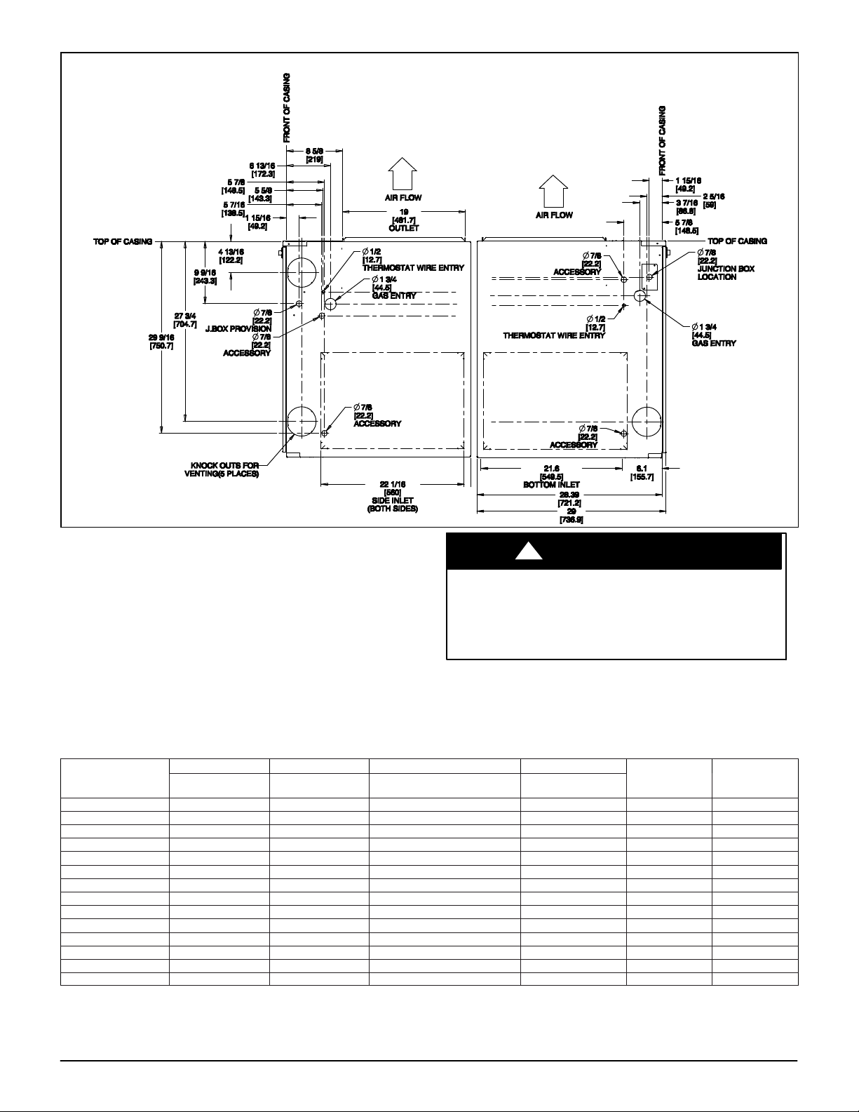
Figure 3 − Dimensional Drawing
FLUE
PROCEDURE 1 — INSTALL FURNACES
A. Upflow/Downflow, Side−by−Side Position
Refer to Figure 3 and Table 2 for appearance and dimensional
drawing of twinned furnaces and their connection locations.
1. Select 2 identical heating and airflow furnaces. (See
Table 2.)
2. Remove outer door and blower access door.
3. For upflow and downflow applications:
a. For upflow applications: Bottom return air usage is
required as part of any upflow return air
configuration. If additional return air is to enter 1 side
of each furnace, in addition to bottom return air, cut
open 1 entire return−air opening in appropriate side
of each furnace. (See Figure 1)
UNIT DAMAGE AND FIRE HAZARD
Failure to follow this warning could result in fire,
personal injury or death.
DO NOT use the back of the furnace for return−air duct
connections, as limit cycling will occur.
b. For downflow applications:
!
Return air can only be connected to bottom opening
of furnace. A common return air plenum is required
for proper auxiliary limit switch operation. (See
Figure 2)
Table 2 – Dimensions − in. (mm) for Single Stage and Two−Stage with PSC Blower
A B C D
CABINET WIDTH
Model Numbers
0451408 14−3/16 (360) 12−9/16 (319) 9−5/16 (237) 12−11/16 (322) 4 (102) 104 (47)
0451412 14−3/16 (360) 12−9/16 (319) 9−5/16 (237) 12−11/16 (322) 4 (102) 107 (49)
0701408 14−3/16 (360) 12−9/16 (319) 9−5/16 (237) 12−11/16 (322) 4 (102) 111 (50)
0701412 14−3/16 (360) 12−9/16 (319) 9−5/16 (237) 12−11/16 (322) 4 (102) 115 (52)
0701716 17−1/2 (445) 15−7/8 (403) 11−9/16 (294) 16 (406) 4 (102) 126 (57)
0901714 17−1/2 (445) 15−7/8 (403) 11−9/16 (294) 16 (406) 4 (102) 127 (58)
0902116 21 (533) 19−3/8 (492) 13−5/16 (338) 19−1/2 (495) 4 (102) 140 (64)
0902120 21 (533) 19−3/8 (492) 13−5/16 (338) 19−1/2 (495) 4 (102) 146 (66)
1101712 17−1/2 (445) 15−7/8 (403) 11−9/16 (294) 16 (406) 4 (102) 135 (61)
1102116 21 (533) 19−3/8 (492) 13−5/16 (338) 19−1/2 (495) 4 (102) 146 (66)
1102122 21 (533) 19−3/8 (492) 13−5/16 (338) 19−1/2 (495) 4 (102) 152 (69)
1352116 21 (533) 19−3/8 (492) 13−5/16 (338) 19−1/2 (495) 4 (102){ 149 (68)
1352422 24−1/2 (622) 22−7/8 (581) 15−1/16 (383) 23 (584) 4 (102){ 163 (74)
1552420 24−1/2 (622) 22−7/8 (581) 15−1/16 (383) 23 (584) 4 (102){ 170 (77)
*5−in. or 6−in. (127 or 152 mm) vent connector may be required in some cases.
{135 and 155 size furnaces require 5 or 6−in. (127 or 152 mm) vents. Use a vent adapter between furnace and vent stack. See Installation Instructions for complete
installation requirements
in (mm)
OUTLET WIDTH
in (mm)
TOP AND BOTTOM FLUE
COLLAR in (mm)
WARNING
BOTTOM INLET
WIDTH in (mm)
COLLAR*
in (mm)
SHIP WT (KG)
443 06 2403 01
Specifications subject to change without notice.
5
Page 6
!
UNIT DAMAGE AND FIRE HAZARD
Failure to follow this warning could result in unit
damage, fire, personal injury or death.
DO NOT use the back or sides of the furnace for
return−air duct connections in downflow position, as limit
switch cycling will occur.
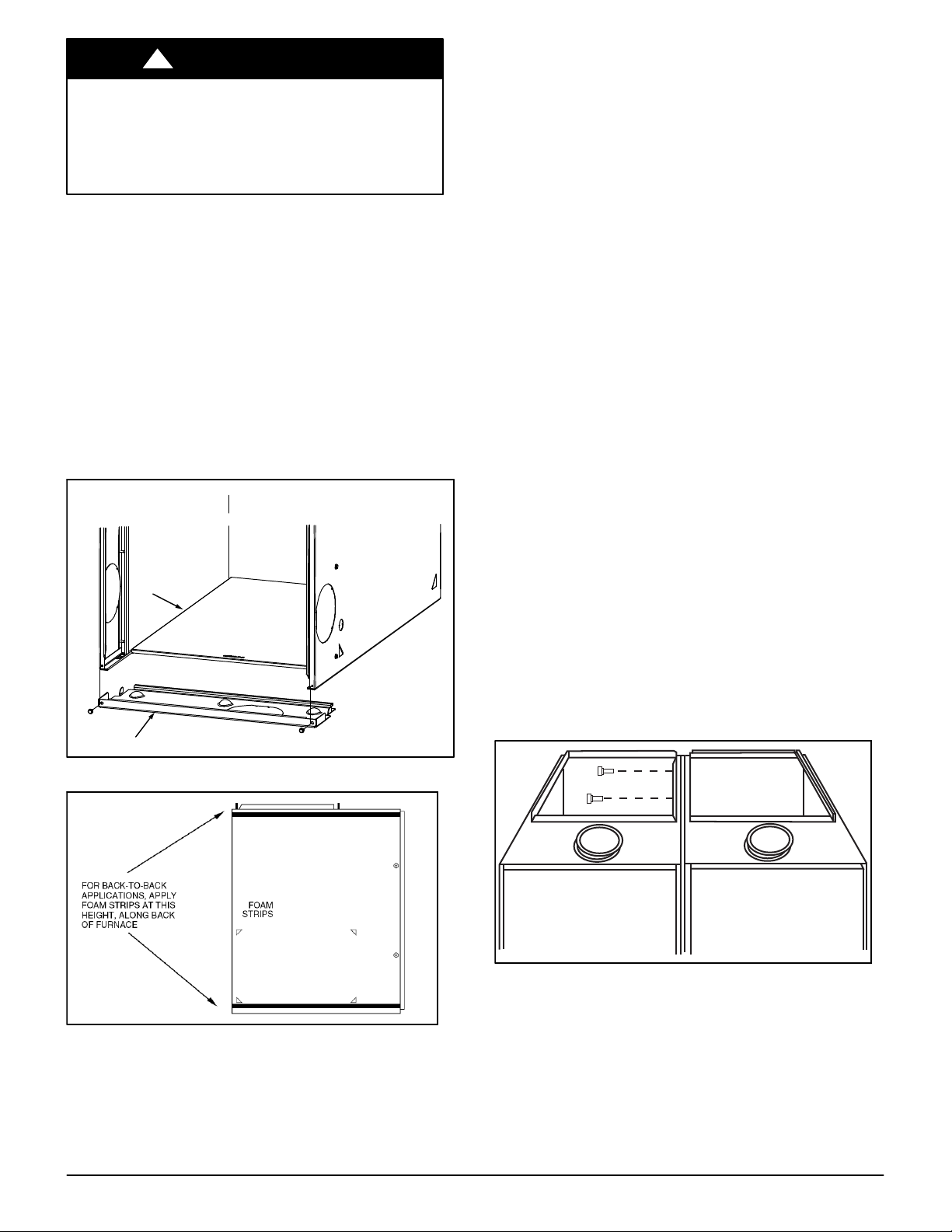
4. Remove bottom closure panels from both furnaces. (See
Figure 4)
a. Lay furnaces on back or sides.
b. Remove 2 screws from bottom front panel.
c. Pull front panel forward to remove.
d. Remove bottom closure panel and discard.
e. Reinstall bottom front panel.
f. Stand furnaces upright.
5. Apply 2 factory−supplied foam strips to mating side of
each furnace. Locate strips equal distance from top and
bottom as shown in Figure 5. Trim off excess material.
6. Remove 7/8−in. diameter accessory hole knock−outs in
blower compartment from mating sides of furnaces. (See
Figure 3)
Bottom
Closure Panel
Bottom Filler Panel
WARNING
8. Bend or remove the supply flanges as required for
upflow or downflow installation. Refer to the furnace
installation instructions for complete details.
9. Position furnaces against each other on return air
plenum, supply air plenum or evaporator coil casing.
Adjust and shim each furnace to align 7/8−in. diameter
holes in both furnaces.
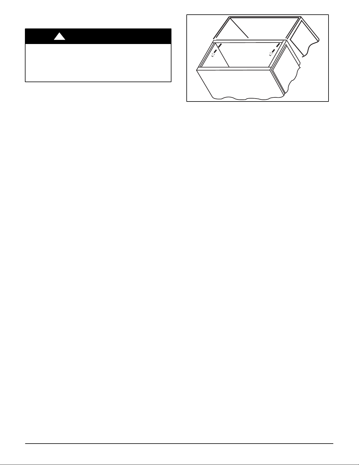
10. Drill two 1/8−in. holes, approximately 1 in. (25 mm)below
discharge flange, from inside top of discharge opening
and through both furnaces. (See Figure 6) Drill two
1/8−in. holes, approximately 1 in. (25 mm)below return
air flange, from inside top of return air opening and
through both furnaces. (See Figure 7 as an example.)
11. Drive 1 factory−supplied screw through each hole and
tighten until furnaces are secure and foam strips have
sealed gap between furnaces.
12. Connect return− and supply−air ducts to furnaces. Seal
duct connections to prevent air leakage.
13. Move 115−v junction box JB in RH furnace (as viewed
from the upflow position) from left−hand side to
right−hand side. Refer to furnace installation instructions
for complete details.
14. Go to PROCEDURE 2A for Single Stage Furnaces or
PROCEDURE 2B for Two−Stage Furnaces.
B. Upflow/Downflow, Back−to−Back Position
Refer to Figure 3 and Table 2 for appearance and dimensional
drawing of twinned furnaces and their connection locations.
1. Select 2 identical heating and airflow furnaces. (See
Table 2)
2. Remove outer door and blower access door.
3. Remove bottom closure panels from both furnaces. (See
Figure 4)
a. Lay furnaces on back or sides.
b. Remove 2 screws from bottom front panel.
c. Pull front panel forward to remove.
d. Remove bottom closure panel and discard.
e. Reinstall bottom front panel.
f. Stand furnaces upright.
4. Applications
Figure 4 − Removing Bottom Closure Panel
Figure 5 − Location of Foam Strips
7. Insert a plastic snap bushing through the 7/8−in.
knock−out from the outside of the casing.
6
Specifications subject to change without notice.
A02232
Figure 6 − Attaching Furnaces Together at Discharge
Opening
a. For upflow applications:
Bottom return air usage is required as part of any
upflow return air configuration. If additional return air
is to enter 1 side of each furnace, in addition to
bottom return air, cut open 1 entire return−air
443 06 2403 01
Page 7
opening in appropriate side of each furnace. (See
Figure 2)
!
UNIT DAMAGE AND FIRE HAZARD
Failure to follow this warning could result in unit
damage, fire, personal injury or death.
DO NOT use the side of the furnace for return−air duct
connections, as limit cycling will occur.
b. For downflow applications:
Return air can only be connected to bottom opening
of furnace. A common return air plenum is required
for proper auxiliary limit switch operation. (See
Figure 3)
5. Apply 2 factory−supplied foam strips to the back of each
furnace. Locate strips equal distance from top and
bottom as shown in Figure 5. Trim off excess material.
6. Determine which side of furnace will be used to route
external extension harness. Remove 7/8−in. diameter
accessory hole knockouts in blower compartment side
selected to attach harness to. (See Figure 3)
7. Bend or remove the supply flanges as required for
upflow or downflow installation. Refer to the furnace
installation instructions for complete details.
8. Position furnaces back−to−back on return−air plenum,
supply air plenum or evaporator coil casing. Adjust and
shim each furnace to align both furnaces.
NOTE: External extension harness cannot be used on the
same side of the furnace that the return air ducts connect to.
Locate harness on opposite side of furnace when side return
air is used.
9. Drill two 1/8−in. holes, approximately 1 in. (25 mm)below
discharge flange, from inside top of discharge opening
and through both furnaces. (Similar to Figure 6) Drill two
1/8−in. holes, approximately 1 in. (25 mm)below return
air flange, from inside top of return air opening and
through both furnaces. (Similar to Figure 7)
10. Drive 1 factory−supplied No. 6 X 3/4−in. LG screw
through each hole and tighten until furnaces are secure
and foam strips have sealed gap between furnaces.
11. Connect return− and supply−air ducts to furnaces. Seal
duct connections to prevent air leakage.
WARNING
A02219
Figure 7 − Attaching Furnaces Together at Return Air
Opening
12. Move 115−v junction box JB in either furnace from
left−hand side to right−hand side if required. Refer to
furnace installation instructions for complete details.
13. Go to Step 2A for Single Stage Furnaces or Step 2B for
Two−Stage Furnaces.
C. Horizontal, Back−to−Back Position
When twinning furnaces in the horizontal position,
consideration must be made to the type of building
construction. Attic floors should be constructed to support
normal live and dead loads of the furnaces and the person(s)
servicing them.
Trusses, wood and metal are engineered for specific
applications, and may not support the weight of two (2)
furnaces suspended from the top chords or the bottom chords
of the trusses. Long horizontals spans may flex or sag,
resulting in damage to the building. Contact the truss
manufacturer for additional design and engineering assistance.
Do not suspend furnaces with straps or suspend furnaces from
roof decking.
For attic installations on a platform (See Figure 8):
1. Construct a platform from 3/4−in. (76 mm) (nominal
plywood), extending out 30 inches (762 mm) from the
front of each furnace.
2. Maintain all clearances to combustibles per the furnace
Installation, Start−up and Operating Instructions.
3. Follow all additional building codes.
4. Long truss spans may require additional support along
the bottom chord of the truss. Consult the truss
manufacturer’s guidelines for engineering assistance.
5. Long rafter or attic joist spans may require additional
support along the bottom of the rafter or joist. Consult
local or regional building codes for design and loading
requirements.
443 06 2403 01
Specifications subject to change without notice.
7
Page 8

Figure 8 − Attic Installation of Horizontal Back−to−Back Furnaces
For suspended installations (See Figure 9) Not recommended
for wood trusses unless approved by the truss manufacturer or
other approved engineering methods):
1. Furnaces may be suspended using two (2) pieces of
1−1/2−in. x 1−1/4−in x 1/4−in. thick cold rolled angle iron
underneath the furnaces and four (4) 3/8−in. diameter
threaded rods.
2. Allow for at least 9 inches (229 mm) in front of each door
for door removal.
3. Each piece of angle iron must be secured to the bottom
of each furnace with at least two (2) #8 x 3/4−in. sheet
metal screws.
4. Maintain all clearances to combustibles per the furnace
Installation, Start−up and Operating Instructions.
5. Unistrut or similar material may be used, provided that
the furnaces do not sag in the middle or bend or twist at
the support ends. The support material must be secured
to the bottom of each furnace in a manner similar to
securing angle iron to the furnace.
Refer to Figure 3 and Table 2 for appearance and dimensional
drawing of twinned furnaces and their connection locations.
1. Select 2 identical heating and airflow furnaces. (See
Table 2)
2. Remove outer door and blower access door.
3. Remove bottom closure panels from both furnaces. (See
Figure 4)
a. Lay furnaces on back or sides.
b. Remove 2 screws from bottom front panel.
A02241
c. Pull front panel forward to remove.
d. Remove bottom closure panel and set aside for
possible use as roll−out protection.
e. Reinstall bottom front panel.
f. Stand furnaces upright.
4. For All Horizontal applications:
Return air can only be connected to bottom opening of
furnace. (See Figure 2) A common return air plenum is
required for proper auxiliary limit switch operation.
!
UNIT DAMAGE AND FIRE HAZARD
Failure to follow this warning could result in unit
damage, fire, personal injury or death.
DO NOT use the side or back of the furnace for
return−air duct connections in the horizontal position, as
limit cycling will occur.
5. Apply 2 factory−supplied foam strips to the back of each
furnace. Locate strips equal distance from top and
bottom as shown in Figure 5. Trim off excess material.
6. Determine which side of furnace will be used to route
external extension harness. Remove 7/8−in. diameter
accessory hole knockouts in blower compartment side
selected to attach harness to. (See Figure 3)
WARNING
8
Specifications subject to change without notice.
443 06 2403 01
Page 9

Figure 9 − Suspended Installation for Horizontal Furnaces Back−to−Back
7. Position furnaces back−to−back on attic platform or
suspended supports. Adjust and shim each furnace to
align both furnaces. Follow all clearance to combustible
material.
8. If furnaces are installed closer than 12 inches above a
deck made from combustible material, provide roll−out
protection as shown in the furnace installation
instructions. The bottom closure pan may be used for
this purpose.
NOTE: DO NOT lay furnace down flat on the side that external
extension harness is installed. Raise furnace up a minimum of
1−1/2 inches (38 mm) above deck so harness does not rub on
casing or deck.
9. Drill two 1/8−in. holes, approximately 1 in. (25 mm)below
discharge flange, from inside top of discharge opening
and through both furnaces. (See Figure 6) Drill two
1/8−in. holes, approximately 1 in. (25 mm)below return
air flange, from inside top of return air opening and
through both furnaces. (Use Figure 6 as an example).
10. Drive 1 factory−supplied No. 6 X 3/4−in. LG screw
through each hole and tighten until furnaces are secure
and foam strips have sealed gap between furnaces.
11. Connect return− and supply−air ducts to furnaces. Seal
duct connections to prevent air leakage.
12. Move 115−v junction box JB in either furnace from
left−hand side to right−hand side if required. Refer to
furnace installation instructions for complete details.
13. Go to PROCEDURE 2A for Single Stage Furnaces or
PROCEDURE 2B for Two−Stage Furnaces.
D. Horizontal, Stacked Together
When twinning furnaces in the horizontal position,
consideration must be made to the type of building
construction. Attic floors should be constructed to support
normal live and dead loads of the furnaces and the person(s)
servicing them.
Trusses, wood and metal are engineered for specific
applications, and may not support the weight of two (2)
furnaces suspended from the top chords or the bottom chords
of the trusses. Long horizontals spans may flex or sag,
resulting in damage to the building. Contact the truss
manufacturer for additional design and engineering assistance.
Do not suspend furnaces with straps or suspend furnaces from
roof decking.
For attic installations on a platform, see Figure 10:
1. Construct a platform from 3/4−in. (nominal plywood),
extending out 30 inches (762 mm) from the front of each
furnace.
2. Maintain all clearances to combustibles per the furnace
Installation, Start−up and Operating Instructions.
3. Follow all additional building codes.
4. Long truss spans may require additional support along
the bottom chord of the truss. Consult the truss
manufacturer’s guidelines for engineering assistance.
5. Long rafter or attic joist spans may require additional
support along the bottom of the rafter or joist. Consult
local or regional building codes for design and loading
requirements.
443 06 2403 01
Specifications subject to change without notice.
9
Page 10

Figure 10 − Attic Installation of Horizontal Furnace Stacked Together
Figure 11 − Suspended Installation for Horizontal Furnaces Stacked Together
3
/8 Theaded Rod
3
/8 Hex Nut
3
/8 Lock Washer
3
/8 Flat Washer
11/2 x 11/2 x 1/4Angle Iron
3
/8 Flat Washer
3
/8 Lock Washer
3
/8 Hex Nut
For suspended installations, see Figure 11. Not recommended
for wood trusses unless approved by the truss manufacturer or
other approved engineering methods):
1. Furnaces may be suspended using two (2) pieces of
1−1/2−in. x 1−1/2−in. x 1/4−in. thick cold rolled angle
iron underneath the furnaces and four (4) 3/8−in.
diameter threaded rods.
10
Specifications subject to change without notice.
2. Allow for at least 9 inches (229 mm) in front of each door
for door removal.
3. Each piece of angle iron must be secured to the bottom
of each furnace with at least two (2) #8 x 3/4−in. sheet
metal screws.
4. Maintain all clearances to combustibles per the furnace
Installation, Start−up and Operating Instructions.
443 06 2403 01
Page 11

5. Unistrut or similar material may be used, provided that
the furnaces do not sag in the middle or bend or twist at
the support ends. The support material must be secured
to the bottom of each furnace in a manner similar to
securing angle iron to the furnace.
Refer to Figure 3 and Table 2 for appearance and dimensional
drawing of twinned furnaces and their connection locations.
1. Select 2 identical heating and airflow furnaces. (See
Table 2)
2. Remove outer door and blower access door.
3. Remove bottom closure panels from both furnaces. (See
Figure 4)
a. Lay furnaces on back or sides.
b. Remove 2 screws from bottom front panel.
c. Pull front panel forward to remove.
d. Remove bottom closure panel and set aside for
possible use as roll−out protection.
e. Reinstall bottom front panel.
f. Stand furnaces upright.
4. For all horizontal applications: Return air can only be
connected to bottom opening of furnace.
5. Apply 2 factory−supplied foam strips to mating side of
each furnace. Locate strips equal distance from top and
bottom as shown in Figure 5.
6. Remove 7/8−in. diameter accessory hole knockouts in
blower compartment from mating sides of furnaces. (See
Figure 3)
7. Insert a plastic snap bushing through the 7/8−in. K.O.
from the outside of the casing.
8. Position furnaces on top of each other on platform or
suspended supports. Adjust and shim each furnace to
align 7/8−in. diameter holes in both furnaces.
9. Drill two 1/8−in. holes, approximately 1 in. (25 mm)below
discharge flange, from inside top of discharge opening
and through both furnaces. (See Figure 6) Drill two
1/8−in. holes, approximately 1 in. (25 mm)above return
air opening flange, from inside blower compartment and
through both furnaces. (See Figure 7)
10. Drive 1 factory−supplied screw through each hole and
tighten until furnaces are secure and foam strips have
sealed gap between furnaces.
11. Connect return− and supply−air ducts to furnaces. Seal
duct connections to prevent air leakage.
12. Move 115−v junction box JB in RH furnace (as viewed
from the upflow position) from left−hand side to
right−hand side. Refer to furnace installation instructions
for complete details.
13. Go to PROCEDURE 2A for Single Stage Furnaces or
PROCEDURE 2B for Two−Stage Furnaces.
PROCEDURE 2 — CONNECT ELECTRICAL
COMPONENTS—HEATING
A. All Single−Stage Models N8MSN & N8MSL Multipoise
Single−Speed Non−Condensing HSI Furnaces
!
FIRE HAZARD
Failure to follow this warning could result in fire,
personal injury or death.
Make no connections between the R 24−vac connector
in 1 furnace and the R 24−vac connector in other
furnace.
WARNING
See Electrostatic Discharge Precaution Section.
The twinning kit can be used for single−stage or two−stage
heating operation. There are 3 harness assemblies included in
this kit. If the furnaces are side−by−side, only 2 harness
assemblies are required. If the furnaces are installed
back−to−back, all 3 harness assemblies included in the kit
must be used.
1. Remove outer doors and blower access doors from both
furnaces.
2. If furnaces are installed back−to−back in any orientation,
the external Extension Harness must be used. The
harness consists of:
a. 54−1/2 inches (1384 mm) of 1/2−in. flexible steel
conduit
b. (2) 90_ conduit connectors
c. (1) 4 wire polarized wiring harness d. (1) 2 wire
polarized wiring harness
3. Install the Extension Harness as follows:
a. Remove lock nuts from the end of each conduit
connector.
b. Route the end of the harness, labeled “twinning kit
harness,” that mates to the TRK relay harness from
the outside of the furnace through the 7/8−in.
knock−out in the casing to the blower compartment.
c. Route the end of the harness that mates to the
4−wire harness through the outside of the furnace
through the 7/8−in. knockout in the casing to the
blower compartment.
d. Install the lock nuts on the 90_ conduit connectors.
e. Install 2 kit−supplied straps approximately 18 inches
(457 mm) from each end of harness.
Single−Stage Heat with Single−Stage Gas−Heat
Thermostat (Field−Supplied)
NOTE: This application allows both furnaces to operate as 1
furnace in gas heat mode as determined by single−stage
thermostat operation. Both furnaces operate in heating mode
simultaneously. See furnace Installation, Start−Up, and
Operating Instructions for further details on this heating mode.
1. Install harness labeled “Main Furnace” with TKR on L/H
Furnace:
The Main Harness includes the TKR relay and Auxiliary
Limit switch on the harness. The harness is also tagged
“Main Furnace” near the ends of the plug connector.
a. Secure relay of TKR harness assembly to LH
furnace blower housing using 2 factory−supplied
screws. (See Figure 12)
NOTE: See Figure 15 for Single Stage furnace Twinning Kit
wiring diagram.
b. Connect TKR white wire labeled W from TKR to LH
furnace control thermostat connection W.
c. Connect TKR black wire labeled C from TKR to LH
furnace control thermostat connection C.
d. Connect yellow wire labeled TEST to LH furnace
control TEST/TWIN terminal.
e. If Extension Harness was used, connect 4−wire
harness to Extension Harness.
NOTE: If Extension Harness will not plug in to L/H and R/H
furnaces, extension harness is installed backward. Remove
extension harness and re−install in correct orientation.
443 06 2403 01
Specifications subject to change without notice.
11
Page 12

Figure 12 − TKR Relay Secured with Factory−Supplied Screws
2. Install Auxiliary Limit Switch (ALS−M) on L/H furnace:
a. Drill 1/8−in. hole in blower housing 12 in. (305
mm)below blower shelf. (See Figure 13)
b. Position ALS−M so reset button faces front of
furnace.
c. Secure bracket to blower housing using a
factory−supplied screw.
d. Disconnect red transformer wire from LH furnace
control 24 VAC connection.
e. Connect red transformer wire connector to ALS−M
wire connector PLC labeled TRAN.
f. Connect orange ALS−M wire connector labeled SEC
1 to LH furnace control 24 VAC terminal.
g. If Extension Harness was used, connect 2−wire
harness to Extension Harness
3. Install Secondary 4−wire harness on R/H furnace:
The Secondary Harness includes the Auxiliary Door Switch
and Auxiliary Limit Switch. The harness is also tagged
“Secondary Furnace” near the plug ends of the harness.
a. Connect red wire labeled R−Secondary to RH
furnace control thermostat connection R.
b. Connect white wire labeled W−Secondary to RH
furnace control thermostat connection W.
c. Connect black wire labeled C−Secondary to RH
furnace control thermostat connection C.
d. Connect yellow wire labeled TEST SECONDARY to
RH furnace control TEST/TWIN terminal.
e. If the furnaces are side−by−side, route loose ends of
4−wire harness from Secondary furnace to Main
furnace through snap bushings previously installed
between furnaces. (See Figure 4)
f. Connect Secondary 4−wire harness into 4−wire Main
harness.
g. If Extension Harness was installed, connect 4−wire
Secondary Harness to the Extension Harness.
4. Install Auxiliary Limit Switch, ALS−S on Secondary
furnace:
a. Drill 1/8−in. hole in blower housing 12 in. (305
mm)below blower shelf. (See Figure 13)
b. Position ALS−S with terminals facing front of furnace.
c. Secure bracket to blower housing using
factory−supplied screw.
12
Specifications subject to change without notice.
5. Install Auxiliary Blower Door Interlock Switch, (See
Figure 13) ILK−1 on Secondary furnace:
NOTE: This kit contains two auxiliary blower door switch
brackets. Assure that switch bracket used matches bracket
used for factory installed blower door switch.
a. Measure along the left edge of the furnace casing, 6
inches (152 mm) down from blower shelf.
b. Drill a 3/16−in. clearance hole through front edge of
blower door support.
c. Insert blower door switch mounting tab behind front
edge of blower door support.
d. Secure auxiliary door switch ILK−
factory−supplied screw.
e. Connect 2−Wire Secondary Harness to 2−wire Main
Harness that was routed through furnace casings.
f. If extension harness was installed, 2−wire Secondary
Harness from Secondary to Main Extension Harness.
NOTE: If Extension Harness will not plug in to L/H and R/H
furnaces, extension harness is installed backward. Remove
extension harness and re−install in correct orientation.
6. Select identical blower motor speed taps at control
center connectors in both furnaces.
!
CAUTION
UNIT DAMAGE HAZARD
Failure to follow this caution may result equipment
damage.
Failure to select identical blower speed taps in both
furnaces can result in overheating of furnace
components and possible loss of furnace operation and
damage to the furnaces.
7. Dress wires to ensure they do not contact sharp or
moving parts nor interfere with blower operation,
removal of filters, or operation of switches.
8. Make all thermostat connections to LH furnace only. See
Figure 15.
1 using
443 06 2403 01
Page 13

Figure 13 − Auxiliary Door Switch
Two −Stage Heat with Two−stage Gas−Heat Thermostat
(Field Supplied)
NOTE: ALL thermostat connections are to be made to LH
furnace control ONLY. (See Figure 16)
NOTE: This application allows only the LH furnace to operate
for first−stage heat mode or both furnaces to operate for
second−stage heat mode as determined by a two−stage
thermostat. See furnace Installation, Start−Up, and Operating
Instructions for further details on this heating mode.
To operate furnaces in two−stage heating mode when a
two−stage thermostat controls the staging, install twinning kit
as described in Single−Stage Heat with Single−Stage Gas
Heat Thermostat, then modify TKR wiring as follows:
a. Disconnect TKR white wire labeled W from the LH
furnace control thermostat connection W.
b. Cut off terminal of TKR white wire labeled W and
strip 1/4 in. (6 mm).
c. Connect two−stage thermostat W2 connection to
TKR white wire labeled W.
!
PERSONAL INJURY HAZARD
Failure to follow this caution could result in intermittent
furnace operation and unit damage.
Supply−air temperature will be uneven left−to−right
when only main system is operating.
NOTE: ALL other two−stage thermostat connections are to be
made to LH furnace control ONLY. (See Figure 16)
B. All Two−Stage Models: F8MTL & G8MTL Two−Speed
Non−Condensing HSI Furnaces with PSC Motors
See Electrostatic Discharge Precaution Section.
The twinning kit can be used for single−stage or two−stage
heating operation. There are 3 harness assemblies included in
this kit. If the furnaces are side−by−side, only 2 harness
assemblies are required. If the furnaces are installed
CAUTION
back−to−back, all 3 harness assemblies included in the kit
must be used.
!
FIRE HAZARD
Failure to follow this warning could result in fire,
personal injury or death.
Make no connections between the R 24−vac connector
in 1 furnace and the R 24−vac connector in other
furnace.
1. Remove outer doors and blower access doors from both
furnaces.
2. If furnaces are installed back−to−back in any orientation,
the external Extension Harness must be used. The
harness consists of:
a. 54−1/2−in. of 1/2−in. flexible steel conduit
b. (2) 90_ conduit connectors
c. (2) 4 wire polarized wiring harness
d. (2) 2 wire polarized wiring harness
3. Install the Extension Harness as follows:
a. Remove lock nuts from the end of each conduit
connector.
b. Route the end of the harness labeled “Twinning Kit
Harness” that mates to the TKR relay harness from
the outside of the furnace through the 7/8−in.
knock−out in the casing to the blower compartment.
c. Route the end of the harness that mates to the
4−wire harness through the outside of the furnace
through the 7/8−in. knockout in the casing to the
blower compartment.
d. Install the lock nuts on the 90_ conduit connectors.
WARNING
443 06 2403 01
Specifications subject to change without notice.
13
Page 14

Two −Stage Heat with Single−Stage Gas−Heat Thermostat
(Field Supplied) (See Figure 17).
NOTE: This application allows both furnaces to operate as 1
furnace in gas heat mode as determined by single−stage
thermostat operation. Both furnaces operate in heating mode
simultaneously. See furnace Installation, Start−Up, and
Operating Instructions for further details on this heating mode.
1. Install harness labeled “Main Furnace” with TKR on L/H
Furnace: The Main Harness includes the TKR relay and
Auxiliary Limit switch on the harness. The harness is
also tagged “Main Furnace” near the ends of the plug
connector.
a. Secure relay of TKR harness assembly to LH
furnace blower housing using 2 factory−supplied
screws. Two new screw holes will have to be drilled
using a 1/8−inch drill bit. See Figure 12 for location of
holes to be drilled.
b. Connect TKR white wire labeled W from TKR to LH
furnace control thermostat connection W/W1.
c. Connect TKR black wire labeled C from TKR to LH
furnace control thermostat connection C.
d. Connect yellow wire labeled TEST to LH furnace
control TEST/TWIN terminal.
e. If Extension Harness was used, connect 4−wire
harness to Extension Harness.
f. Turn TT set−up switch on L/H control board to “OFF.”
(See Figure 14)
g. Turn TT set−up switch on R/H control board to “ON.”
NOTE: If Extension Harness will not plug in to L/H and R/H
furnaces, extension harness is installed backward. Remove
extension harness and re−install in correct orientation.
2. Install Auxiliary Limit Switch (ALS−M) on L/H furnace:
a. Drill 1/8−in. hole in blower housing 12 in. (305
mm)below blower shelf. (See Figure 13)
b. Position ALS−M so reset button faces front of
furnace.
c. Secure bracket to blower housing using a
factory−supplied screw.
d. Disconnect red transformer wire from LH furnace
control 24 VAC connection.
e. Connect red transformer wire connector to ALS−M
wire connector PLC labeled TRAN.
f. Connect ALS−M orange wire connector labeled SEC
1 to LH furnace control 24 VAC terminal.
g. If Extension Harness was used, connect 2−wire
harness to Extension Harness
3. Install Secondary 4−wire harness on R/H furnace:
The Secondary Harness includes the Auxiliary Door Switch
and Auxiliary Limit Switch. The harness is also tagged
“Secondary Furnace” near the plug ends of the harness.
a. Connect red wire labeled R−Secondary to RH
furnace control thermostat connection R.
b. Connect white wire labeled W−Secondary to RH
furnace control thermostat connection W/W1.
c. Connect black wire labeled C−Secondary to RH
furnace control thermostat connection C.
d. Connect yellow wire labeled TEST SECONDARY to
RH furnace control TEST/TWIN terminal.
e. If the furnaces are side−by−side, route loose ends of
4−wire harness from Secondary furnace to Main
furnace through snap bushings previously installed
between furnaces.
f. Connect Secondary 4−wire harness into 4−wire Main
harness.
14
Specifications subject to change without notice.
g. If Extension Harness was installed, connect 4−wire
Secondary Harness to the Extension Harness.
4. Install Auxiliary Limit Switch, ALS−S on Secondary
furnace:
a. Drill 1/8−in. hole in blower housing 12 in. (305
mm)below blower shelf. (See Figure 13)
b. Position ALS−S with terminals facing front of furnace.
c. Secure bracket to blower housing using
factory−supplied screw.
5. Install Auxiliary Blower Door Interlock Switch, ILK−1 on
Secondary furnace:
NOTE: This kit contains two auxiliary blower door switch
brackets. Assure that switch bracket used matches bracket
used for factory installed blower door switch.
a. Measure along the left edge of the furnace casing, 6
inches (152 mm) down from blower shelf.
b. Drill a 3/16−in. clearance hole through front of blower
door support.
c. Insert blower door switch mounting tab behind blower
door support
d. Secure auxiliary door switch ILK−1 using
factory−supplied shallow head screw.
e. Connect 2−Wire Secondary Harness to 2−wire Main
Harness that was routed from Secondary to Main
furnace casings.
f. If extension harness was installed, 2−wire Secondary
Harness to Extension Harness.
NOTE: If Extension Harness will not plug in to L/H and R/H
furnaces, extension harness is installed backward. Remove
extension harness and re−install in correct orientation.
6. Select identical blower motor speed taps at control
motor connectors in both furnaces.
!
CAUTION
UNIT DAMAGE HAZARD
Failure to follow this caution may result in unit damage.
Failure to select identical blower speed taps in both
furnaces can result in overheating of furnace
components and possible loss of furnace operation and
damage to the furnaces
7. Dress wires to ensure they do not contact sharp or
moving parts nor interfere with blower operation,
removal of filters, or operation of switches.
8. Make all thermostat connections to LH furnace only.
Two −Stage Heat with Two−stage Gas−Heat Thermostat
(Field Supplied)
NOTE: ALL thermostat connections are to be made to LH
furnace control ONLY. (See Figure 17)
NOTE: This application allows both furnaces to operate in low
heat for first−stage heat mode or both furnaces to operate in
high heat for second−stage heat mode as determined by a
two−stage thermostat. See furnace Installation, Start−Up, and
Operating Instructions for further details on this heating mode.
To operate furnaces in two−stage heating mode when a
two−stage thermostat controls the staging, install twinning kit
as described in the two−stage heat with single−stage gas heat
thermostat:
a. Turn TT set−up switch on L/H control board to “ON.”
b. Turn TT set−up switch on R/H control board to “ON.”
NOTE: ALL other two−stage thermostat connections are to be
made to LH furnace control ONLY. (See Figure 17)
443 06 2403 01
Page 15

Figure 14 − TT Switch Settings
Thermostat
Typ e
One Stage
Thermostat
Two Stage
Thermostat
Main
(LH)
TT Switch 1
OFF ON
ON ON
Secondary
(RH)
TT Switch 1
PROCEDURE 3 — CONNECT ELECTRICAL
COMPONENTS−COOLING
!
ELECTRICAL OPERATION HAZARD
Failure to follow this warning could result in fire,
personal injury or death.
Failure to follow warning could result in fire, personal
injury or death. Make no connections between the R
24−vac connector in one furnace and the R 24−vac
connector in other furnace.
When installing twinned outdoor units with twinned gas
furnaces, it is necessary to use a field−supplied 24−vac
pilot−duty relay and a field−supplied 24/115−vac transformer
as shown in Figure 15, Figure 16, or Figure 17 to prevent
overloading furnace 24/115−vac transformer.
WARNING
PROCEDURE 4 — VENTING
Refer to Installation, Start−Up, and Operating Instructions
supplied with each furnace for venting information.
!
UNIT DAMAGE HAZARD
Failure to follow this caution may result in unit damage
When common−venting twinned, Category I
(negative−pressure venting), non−condensing furnaces,
excessive condensate may occur as a result of
oversized vent systems. Dedicated vents and/or proper
vent sizing, per the current edition of the National Fuel
Gas Code, will reduce the potential for condensation.
CAUTION
PROCEDURE 5 — GAS SUPPLY PIPING
NOTE: All gas connections must be made through exposed
outer side of each furnace. Do not common connect any
connection other than supply and return−air ducts.
Furnaces are recommended to be provided with a single
shutoff valve. However, individual shutoff valves may be
required by local codes or jurisdictions. Refer to Installation,
Start−Up, and Operating Instructions provided with each
furnace for additional gas supply information.
PROCEDURE 6 — ELECTRICAL SUPPLY
CONNECTIONS
NOTE: All electrical power connections must be made through
exposed outer side of each furnace. Do not common connect
any connection other than supply− and return−air ducts.
1. Each furnace shall be connected to its own 115−vac
power supply. The twinning kit installation interconnects
the furnaces, allowing them to operate as a single
furnace. The L1 (black) connection to each furnace must
be connected to circuit breakers connected to the same
service panel 115−vac phase leg.
On single−phase (residential) systems, each furnace
circuit breaker should be located directly across from
each other in service panel, or each furnace circuit
breaker should be located on the same side of service
panel, but must skip 1 space to be connected to the
same leg of the 1−phase power supply.
On 3−phase (commercial) systems, each furnace circuit
breaker should be located directly across from each
other in service panel, or each furnace circuit breaker
should be located on the same side of service panel, but
must skip 2 spaces to be connected to the same leg of
the 3−phase power supply.
The proper 115−vac phasing of furnace connections
permits 24−vac transformer phasing as described below.
2. Phasing of the connected 24−vac transformer
secondary circuits can be determined with the LED
status of both furnaces. See furnace Installation,
Start−Up, and Operating Instructions and status code
labels on blower doors. The furnaces’ transformers’
black leads should be connected to XFMR connectors
and white leads to NEUTRAL connectors on controls. If
1 or both LEDs are rapidly flashing, disconnect lead at
TEST/TWIN terminal of LH furnace and observe LED at
each furnace.
To verify that the furnaces are in phase, check from Main
furnace L1 to Secondary furnace L1 with a voltmeter. If
the furnaces are in phase, the voltage between both
furnaces will be ZERO.
IF:
a. Both LEDs are flashing a heart beat. System phasing
is okay.
b. One or both LEDs are flashing status code 10:
(1.) Line voltage polarity is reversed
(2.) Reverse 24 VAC and COM in furnace flashing
status code 10.
c. One LED is off, 1 LED is flashing a heart beat.
(1.) The 24 VAC circuit is inoperative on furnace with
LED light off.
(2.) Check transformers, auxiliary limits, and door
switches in both furnaces and correct problem.
d. One or both LEDs are dim or flickering. Furnaces are
on different phase legs. Disconnect TWIN/TEST
lead. If both LEDs are flashing a heart beat when
TWIN/TEST is disconnected, furnace line voltage
power supply is out of phase.
3. Reconnect lead at TWIN/TEST terminal of LH furnace
and observe LED at each furnace. The LEDs will flash a
heart beat for proper phasing.
443 06 2403 01
Specifications subject to change without notice.
15
Page 16

PROCEDURE 7 — START−UP AND ADJUSTMENT
Refer to Installation, Start−Up, and Operating Instructions
supplied with furnaces for detailed information.
1. Shut off all power and gas to both furnaces.
2. Position blower off delay switches on controls in BOTH
furnaces to SAME desired gas heat blower off delay.
(See Figure 18 and Figure 19) See furnace Installation,
Start−Up, and Operating Instructions for further details.
3. Attach twinning connection wiring label above the
existing furnace wiring label on the inside of the L/H
furnace blower access door. Use the following labels for
the following applications:
Single Stage furnaces with single−stage thermostat,
337070−101 Single Stage furnaces with two−stage thermostat,
337069−101 Two Stage furnaces with single−stage or
two−stage thermostat, 337068−101
4. Attach twinning reference label 327956–101 on outside
of blower access door of RH furnace blower door.
5. Turn on power and gas to both furnaces.
6. Reinstall blower access doors on both furnaces.
Figure 15 − Single−Stage Furnace and A/C Single−Stage Thermostat
7. Operate furnaces through 2 cycles in each mode to
confirm correct operation by operating only thermostat.
a. Single−stage gas heating thermostat R−to−W
operates both furnaces gas heat mode. First stage of
a two−stage thermostat causes LH furnace to
operate in gas−heat mode. Second stage of a
two−stage thermostat causes both furnaces to
operate in gas heat mode.
b. Single stage thermostat operates first or second
stage of a two stage furnace, based on the furnace
control board algorithm. two−stage heating
thermostat R−to−W/W1 will operate both furnaces in
low heat mode. Thermostat R to W/W1 and−W2
causes both furnaces to operate in high gas−heat
mode.
c. Thermostat R−to−G for continuous fan or
low−cooling blower.
d. Cooling thermostat R−to−G−and−Y for single−speed
cooling blower.
8. Reinstall control doors on both furnaces.
9. Instruct user in operation of furnace and thermostat.
16
Specifications subject to change without notice.
443 06 2403 01
Page 17

Figure 16 − Single−Stage Furnace and A/C Two−Stage Thermostat
Figure 17 − Two−Stage Furnaces and 1−Stage A/C Unit − One or Two−Stage Thermostat
443 06 2403 01
Specifications subject to change without notice.
17
Page 18

Figure 18 − Single−Stage Furnace Control
J2 JUMPER
24−V THERMOSTAT
TERMINALS
3−AMP FUSE
LED OPERATION &
DIAGNOSTIC LIGHT
115 −VAC (L2) NEUTRAL
CONNECTIONS
BLOWER SPEED
SELECTION TERMINALS
COM/BLUE
NEUTRAL
L2
SPARE1
OFF−DELAY
J2
BLW
SPARE1
SPARE2
HEAT
90 150
120 180
HUM
24VAC
24VAC/RED
SPARE2
(115 VAC 1.0 AMP MAX.)
TWINNING AND/OR
COMPONENT TEST
TERMINAL
115 VAC
(L1) LINE VOLTAGE
CONNECTION
L1
EAC 1 AMP
XFMR
EAC TERMINAL
HUMIDIFIER TERMINAL
(24−VAC 0.5 AMP MAX)
TRANSFORMER 24−VAC
CONNECTIONS
P1 − LOW VOLTAGE MAIN
HARNESS CONNECTOR
HUM
HUMIDIFIER
TERMINAL
115 −VAC
P2
IND
HSI
P2−HOT SURFACE IGNITOR (HSI) & INDUCER MOTOR (IND) CONNECTOR
SETUP SWITCHES THERMOSTAT
24−V THERMOSTAT
TERMINALS
3−AMP FUSE
LED OPERATION &
DIAGNOSTIC LIGHT
115 −VAC (L2) NEUTRAL
CONNECTIONS
Figure 19 − Two−Stage Furnace Control
TYPE AND HEAT OFF−DELAY
TT
OFF
DLY
HUM
24VAC
COM/BLUE
24VAC/RED
TWINNING AND/OR COM-
PONENT TEST TERMINAL
SW1
115 VAC (L1) LINE
VOLTAGE CONNECTION
HUMIDIFIER TERMINAL
(24−VAC 0.5 AMP MAX)
TRANSFORMER 24VAC
CONNECTIONS
P1 − LOW VOLTAGE MAIN
HARNESS CONNECTOR
18
BLOWER SPEED
SELECTION TERMINALS
SPARE1
SPARE1 SPARE2
SPARE2
(115 VAC 1.0 AMP MAX.)
EAC TERMINAL
EAC 1 AMP
XFMR
Specifications subject to change without notice.
HUM
HUMIDIFIER
TERMINAL
115 −VAC
P2−HOT SURFACE IGNITOR (HSI) &
INDUCER MOTOR CONNECTOR
443 06 2403 01
Page 19

PROCEDURE 8 — SEQUENCE OF OPERATION
See Figure 15, Figure 16, or Figure 17 and Figure 20 or
Figure 21 for single−speed non−condensing furnace twinning
connection and schematic wiring diagrams while reviewing the
sequence of operation.
Twinning operation is controlled by LH furnace. The
TWIN/TEST and C connection wires ensure the 2 furnaces
coordinate their blower operation. When either furnace
requires blower operation, both furnaces operate their blowers
at the same speed. Both furnaces operate simultaneously in
the same mode: heat, cool, or continuous fan. Exceptions can
occur if a safety switch on either furnace is activated (such as
pressure switch, flame roll−out switch, main limit switch, draft
safeguard switch, twinning kit auxiliary limit switch, or
flame−proving sensor). In such a case, the other furnace
continues to operate unless open switch is the flame roll−out,
main limit, or twinning kit auxiliary limit switch, in which case
both furnaces respond.
Before performing component test, disconnect TKR yellow wire
labeled TEST from LH furnace control TEST/TWIN terminal.
After removing yellow wire, component test can be initiated on
each furnace individually as stated in Installation, Start−Up,
and Operating Instructions.
Single−Stage Heat with Single−Stage Gas−Heat
Thermostat
See Section I, Procedure 2 for furnace and kit components
used.
1. Single−stage thermostat causes both furnaces to
operate in heating mode.
2. Operation in ALL modes is the same for twinned
furnaces as for an individual furnace. See furnace
Installation, Start−Up, and Operating Instructions for
more information on sequence of operation.
Two−Stage Heat with Two−stage Gas−Heat Thermostat
See Section I, Procedure 2 for furnace and kit components
used.
1. The two−stage thermostat causes the furnaces to
operate in first−stage heat (LH furnace operates in heat
while RH furnace blower operates but RH furnace is not
heating) or causes the furnaces to operate in
second−stage heat (both furnaces operate in heat),
depending on whether 1 or 2 thermostat stages are
calling for heat.
2. Operation in ALL modes is the same for twinned
furnaces as for an individual furnace. See furnace
Installation, Start−Up, and Operating Instructions for
more information on sequence of operation.
443 06 2403 01
Specifications subject to change without notice.
19
Page 20

Figure 20 − Wiring Diagram for Single Stage, Non−Condensing Furnaces
20
Specifications subject to change without notice.
443 06 2403 01
Page 21

Figure 21 − Wiring Diagram for Two−Stage, Non−Condensing Furnaces
443 06 2403 01
Specifications subject to change without notice.
21
Page 22

22
Copyright 2018 International Comfort Product S PO Box 128 S Lewisburg, TN 37091 USA
Specifications subject to change without notice.
443 06 2403 01
 Loading...