

ICP N9MSB0401410A1, N9MSB0601410A1, N9MSB0601714A1, N9MSB0801716A1, N9MSB0802120A1 Installation Guide
...Page 1
These instructions must be read and understood completely before attempting installation.
Safety Labeling and Signal Words
DANGER, WARNING, CAUTION, and NOTE
The signal words DANGER, WARNING,
CAUTION, and NOTE are used to identify levels of
hazard seriousness. The signal word DANGER is
only used on product labels to signify an immediate
hazard. The signal words WARNING, CAUTION,
and NOTE will be used on product labels and
throughout this manual and other manual that may
apply to the product.
DANGER - Immediate hazards which will result in
severe personal injury or death.
WARNING - Hazards or unsafe practices which
could result in severe personal injury or death.
CAUTION - Hazards or unsafe practices which
may result in minor personal injury or product or
property damage.
NOTE - Used to highlight suggestions which will
result in enhanced installation, reliability, or
operation.
TABLE OF CONTENTS
SAFETY CONSIDERATIONS .............................. 3
INTRODUCTION ......................................... 4
CODES AND STANDARDS ................................ 4
ELECTROSTATIC DISCHARGE (ESD) PRECAUTIONS ....... 5
DIMENSIONS NEW 6/7/12 ................................ 6
LOCATION .............................................. 7
LOCATION RELATIVE TO COOLING EQUIPMENT ........... 9
AIR FOR COMBUSTION AND VENTILATION ................ 9
CONDENSATE TRAP .................................... 12
INSTALLATION .......................................... 19
UPFLOW INSTALLATION ................................. 19
DOWNFLOW INSTALLATION .............................. 20
HORIZONTAL INSTALLATION ............................. 23
FILTER ARRANGEMENT ................................. 24
AIR DUCTS ............................................. 28
GAS PIPING ............................................. 28
ELECTRICAL CONNECTIONS ............................. 30
J-BOX INSTALLATION ................................... 31
VENTING ............................................... 35
SPECIAL VENTING REQUIREMENTS
FOR INSTALLATIONS IN CANADA ........................ 35
DIRECT VENT / 2-PIPE SYSTEM .......................... 39
VENTILATED COMBUSTION AIR .......................... 39
TERMINATION REQUIREMENTS FOR THE PROVINCES OF ALBERTA
AND SASKATCHEWAN ................................... 39
INSTALLING THE VENT TERMINATION .................... 48
MAXIMUM EQUIVALENT VENT LENTH - FEET (METERS) .... 53
MAXIMUM ALLOWABLE EXPOSED VENT
LENGTHS IN UNCONDITIONED SPACE ................... 56
Portions of the text and tables are reprinted from NFPA 54/ANSI Z223.t -2009_, with permission of National Fire Protection Association, Quincy, MA 02269 and American Gas Association, Washington, DC
20001. This reprinted material is not the complete and official position of the NFPA or ANSI, on the referenced subject, which is represented only by the standard in its entirety,
Signal Words in Manuals
The signal word WARNING is used throughout
this manual in the following manner:
The signal word CAUTION is used throughout
this manual in the following manner:
Signal Words on Product Labeling
Signal words are used in combination with
colors and/or pictures or product labels.
z_ Safety-alert symbol
When you see this symbol on the unit and in
instructions or manuals, be alert to the
potential for personal injury.
IS09001
Use of the AHRI Certified TM Mark indicates a
manufacturer's participation in the program.
For verification of certification for individual
products, go to www.ahddirectory,org ,
INSTALLER: Affix these instructions on or adjacent to the
furnace.
CONSUMER: Retain these instructions for future
reference.
PrintedinU.S.A. 440 01 4101 03 Aug.2012
Page 2
Required Notice for Massachusetts Installations
Important
The Commonwealth of Massachusetts requires compliance with regulation 248 CMR as follows:
5.08: Modifications to NFPA-54, Chapter 10
2) Revise 10.8.3 by adding the following additional requirements:
(a)
For all side wall horizontally vented gas fueled equipment installed in every dwelling, building or structure used in whole or in part for residential
purposes, including those owned or operated by the Commonwealth and where the side wall exhaust vent termination is less than seven (7) feet
above finished grade in the area of the venting, including but not limited to decks and porches, the following requirements shall be satisfied:
1,
INSTALLATION OF CARBON MONOXIDE DETECTORS. At the time of installation of the side wall horizontal vented gas fueled equipment, the
installing plumber or gasfitter shall observe that a hard wired carbon monoxide detector with an alarm and battery back-up is installed on the floor
level where the gas equipment is to be installed, in addition, the installing plumber or gasfitter shall observe that a battery operated or hard wired
carbon monoxide detector with an alarm is installed on each additional level of the dwelling, building or structure served by the side wall
horizontal vented gas fueled equipment. It shall be the responsibility of the property owner to secure the services of qualified license professionals
for the installation of hard wired carbon monoxide detectors.
a. In the event that the side wall horizontally vented gas fueled equipment is installed in a crawl space or an attic, the hard wired carbon
monoxide detector with alarm and battery back-up may be installed on the next adjacent floor level.
b. In the event that the requirements of this subdivision can not be met at the time of completion of installation, the owner shall have a period of
thirty (30) days to comply with the above requirement; provided, however, that during said thirty (30) day period, a battery operated carbon
monoxide detector with an alarm shall be installed.
2. APPROVED CARBON MONOXIDE DETECTORS. Each carbon monoxide detector as required in accordance with the above provisions shall
comply with NFPA 720 and be ANSI/UL 2034 listed and IAS certified.
3. SIGNAGE. A metal or plastic identification plate shall be permanently mounted to the exterior of the building at a minimum height of eight (8) feet
above grade directly in line with the exhaust vent terminal for the horizontally vented gas fueled heating appliance or equipment. The sign shall
read, in print size no less than one-half (1/2) inch in size, "GAS VENT DIRECTLY BELOW. KEEP CLEAR OF ALL OBSTRUCTIONS".
4. INSPECTION. The state of local gas inspector of the side wall horizontally vented gas fueled equipment shall not approve the installation unless,
upon inspection, the inspector observes carbon monoxide detectors and signage installed in accordance with the provisions of 248 CMR
5.08(2)(a) 1 through 4.
(b) EXEMPTIONS: The following equipment is exempt from 248 CMR 5.08(2)(a) 1 through 4:
1. The equipment listed in Chapter 10 entitled "Equipment Not Required To Be Vented" in the most current edition of NFPA 54 as adopted by the
Board; and
2. Product Approved side wall horizontally vented gas fueled equipment installed in a room or structure separate from the dwelling, building or
structure used in whole or in part for residential purposes.
(c)
MANUFACTURER REQUIREMENTS - GAS EQUIPMENT VENTING SYSTEM PROVIDED. When the manufacturer of Product Approved side wall
horizontally vented gas equipment provides a venting system design or venting system components with the equipment, the instructions provided by
the manufacturer for installation of the equipment and the venting system shall include:
1. Detailed instructions for the installation of the venting system design or the venting system components; and
2. A complete parts list for the venting system design or venting system.
(d)
MANUFACTURER REQUIREMENTS - GAS EQUIPMENT VENTING SYSTEM NOT PROVIDED. When the manufacturer of a Product Approved side
wall horizontally vented gas fueled equipment does not provide the parts for venting the flue gases, but identifies "special venting systems", the
following requirements shall be satisfied by the manufacturer:
1. The referenced "special venting system" instructions shall be included with the appliance or equipment installation instructions; and
2. The "special venting systems" shall be Product Approved by the Board, and the instructions for that system shall include a parts list and detailed
installation instructions.
(e)
A copy of all installation instructions for all Product Approved side wall horizontally vented gas fueled equipment, all venting instructions, all parts lists
for venting instructions, and/or all venting design instructions shall remain with the appliance or equipment at the completion of the installation.
For questions regarding these requirements, please contact the Commonwealth of Massachusetts Board of State Examiners of Plumbers and Gas
Fitters, 239 Causeway Street, Boston, MA 02114.617-727-9952
2 Specifications are subject to change without notice. 440 01 4101 03
Page 3
Safety Considerations
FIRE, EXPLOSION, ELECTRICAL SHOCK, AND
CARBON MONOXIDE POISONING HAZARD
Failure to follow this warning could result in dangerous
operation, personal injury, death, or property damage.
Improper installation, adjustment, alteration, service,
maintenance, or use can cause carbon monoxide
poisoning, explosion, fire, electrical shock, or other
conditions which may cause personal injury or property
damage. Consult a qualified service agency, local gas
supplier, or your distributor or branch for information or
assistance. The qualified service agency must use
only factory-authorized and listed kits or accessories
when modifying this product.
FIRE HAZARD
Failure to follow this warning could result in personal
injury, death, or property damage.
Solvent cements and primers are combustible. Keep
away from heat, sparks and open flame. Use only in
well-ventilated areas. Avoid breathing in vapor or
allowing contact with skin or eyes.
FURNACE RELIABILITY HAZARD
Failure to follow this caution may result in unit
component damage.
Application of this furnace should be indoors with
special attention given to vent sizing and material, gas
input rate, air temperature rise, unit leveling, and unit
sizing.
Improper installation, adjustment, alteration, service,
maintenance, or use can cause explosion, fire, electrical shock,
or other conditions which may cause personal injury or property
damage. Consult a qualified service agency, local gas supplier,
or your distributor or branch for information or assistance. The
qualified installer or agency must use only factory-authorized
and listed kits or accessories when modifying this product.
Refer to the individual instructions packaged with the kits or
accessories when installing.
Installing and servicing heating equipment can be hazardous
due to gas and electrical components. Only trained and
qualified personnel should install, repair, or service
heating equipment. Untrained personnel can perform basic
maintenance functions such as cleaning and replacing air
filters. All other operations must be performed by trained
service personnel. When working on heating equipment,
observe precautions in literature, on tags, and on labels
attached to or shipped with furnace and other safety
precautions that may apply.
These instructions cover minimum requirements and conform
to existing national standards and safety codes. In some
instances, these instructions exceed certain local codes and
ordinances, especially those that may not have kept up with
changing residential construction practices. We require these
instructions as a minimum for a safe installation.
Follow all safety codes. Wear safety glasses, protective
clothing, and work gloves. Have a fire extinguisher available.
Read these instructions thoroughly and follow all warnings or
cautions included in literature and attached to the unit.
CUT HAZARD
Failure to follow this caution may result in personal
injury.
Sheet metal parts may have sharp edges or burrs. Use
care and wear appropriate protective clothing, safety
glasses and gloves when handling parts, and servicing
furnaces.
This is the safety-alert symbol /_. When you see this symbol
on the furnace and in instructions or manuals, be alert to the
potential for personal injury.
Understand the signal words DANGER, WARNING, and
CAUTION. These words are used with the safety-alert symbol.
DANGER identifies the most serious hazards which will result
in severe personal injury or death. WARNING signifies a
hazard which could result in personal injury or death.
CAUTION is used to identify hazards which may result in minor
personal injury or product and property damage. NOTE and
NOTICE are used to highlight suggestions which wilt result in
enhanced installation, reliability, or operation.
1. Use only with type of gas approved for this furnace.
Refer to the furnace rating plate.
2. Install this furnace only in a location and position as
specified in the "Location" section of these instructions.
3. Provide adequate combustion and ventilation air to the
furnace space as specified in "Air for Combustion and
Ventilation" section.
4. Combustion products must be discharged outdoors.
Connect this furnace to an approved vent system only,
as specified in the "Venting" section of these
instructions.
5. Never test for gas leaks with an open flame. Use a
commercially available soap solution made specifically
for the detection of leaks to check all connections, as
specified in the "Gas Piping" section.
6. Always install furnace to operate within the furnace's
intended temperature-rise range with a duct system
which has an external static pressure within the
allowable range, as specified in the "Start-Up,
Adjustments, and Safety Check" section. See furnace
rating plate.
7. When a furnace is installed so that supply ducts carry air
circulated by the furnace to areas outside the space
containing the furnace, the return air shall also be
handled by duct(s) sealed to the furnace casing and
terminating outside the space containing the furnace.
See "Air Ducts" section.
8. A gas-fired furnace for installation in a residential
garage must be installed as specified in the warning box
in the "Location" section. (See Figure 4)
9. The furnace may be used for construction heat provided
that the furnace installation and operation complies with
the first CAUTION in the LOCATION section on page 7
of these instructions.
10. These Multipoise Gas-Fired Furnaces are CSA
design-certified for use with natural and propane gases
(see furnace rating plate) and for installation in alcoves,
attics, basements, closets, utility rooms, crawlspaces,
and garages. The furnace is factory-shipped for use
with natural gas. A CSA (A.G.A. and C.G.A.) listed
440 01 4101 03 Specificationssubjectto change without notice. 3
Page 4
accessory gas conversion kit is required to convert
furnace for use with propane gas.
11.
See Table 1 for required clearances to combustible
construction.
12.
Maintain a 1-in. (25 mm) clearance from combustible
materials to supply air ductwork for a distance of 36-in.
(914 mm) horizontally from the furnace. See NFPA 90B
or local code for further requirements.
Minimum Clearances to
Table 1 Combustible Materials for All Units
POSITION
CLEARANCE
In(mm)
REAR 0
FRONT (Combustion air openings in
furnace and in structure)
1(25)
Recommended for service *24 (610)
All Sides of Supply Plenum "1 (25)
Sides 0
Vent 0
Top of Furnace 1 (25)
* Consult local building codes
13.
These furnaces SHALL NOT be installed directly on
carpeting, combustible tile, or any other combustible
material other than wood flooring. In downfiow
installations, factory accessory floor base MUST be
used when installed on combustible materials and wood
flooring. Special base is not required when this furnace
is installed on manufacturer's Coil Assembly or when
Coil Box is used. See Table 1 for clearance to
combustible construction information.
Introduction
The 4-way multipoise Category IV condensing furnace is CSA
design-certified as a direct vent (2-pipe) or non-direct vent
(1-pipe) furnace. (See Figure 3) The furnace is
factory-shipped for use with natural gas. The furnace can be
converted in the field for use with propane gas when a
factory-supplied conversion kit is used. Refer to the furnace
rating plate for conversion kit information.
These furnaces are not approved for installation in recreational
vehicles or outdoors. Single-stage furnaces (40k through
120k) are approved for installation in manufactured
housing/mobile homes with manufacturer approved accessory.
The conversion kit is required for use with both natural and
propane gas. The furnace must also be installed on a
factory-supplied accessory combustible floor base or
evaporator coil casing.
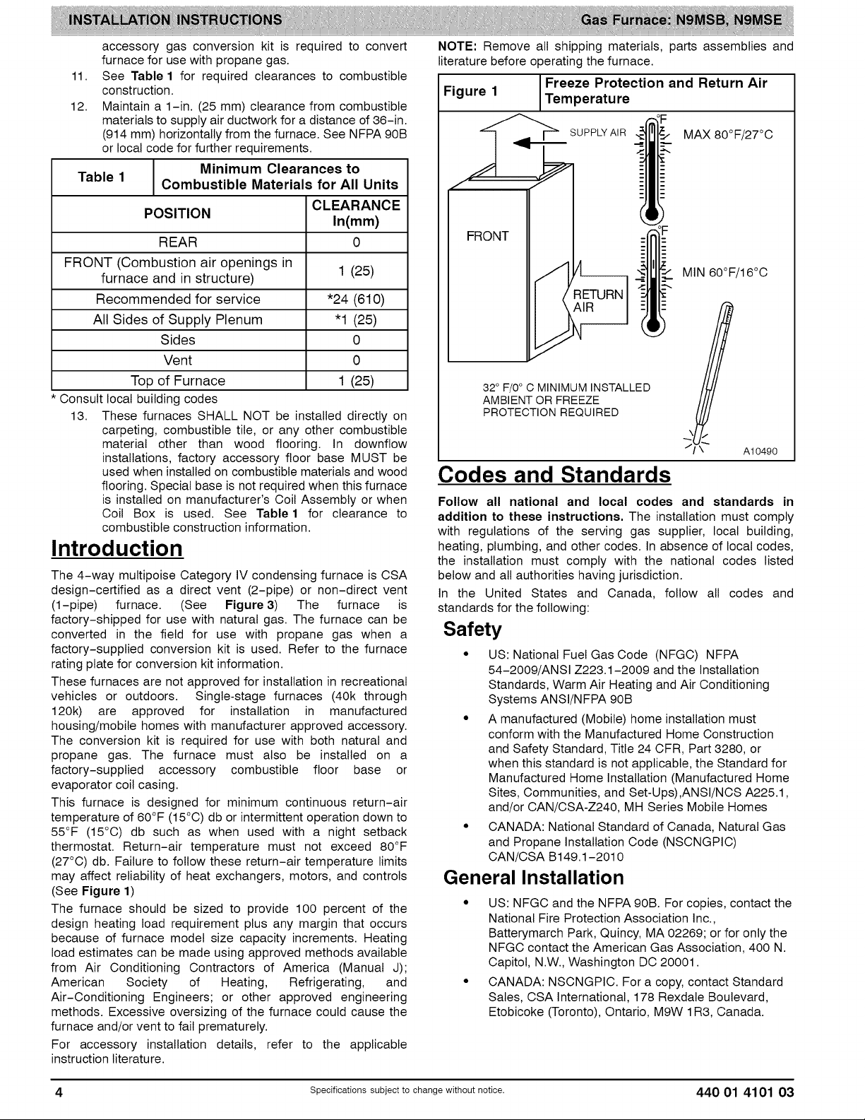
This furnace is designed for minimum continuous return-air
temperature of 60°F (15°C) db or intermittent operation down to
55°F (15°C) db such as when used with a night setback
thermostat. Return-air temperature must not exceed 80°F
(27°C) db. Failure to follow these return-air temperature limits
may affect reliability of heat exchangers, motors, and controls
(See Figure 1)
The furnace should be sized to provide 100 percent of the
design heating load requirement plus any margin that occurs
because of furnace model size capacity increments. Heating
load estimates can be made using approved methods available
from Air Conditioning Contractors of America (Manual J);
American Society of Heating, Refrigerating, and
Air-Conditioning Engineers; or other approved engineering
methods. Excessive oversizing of the furnace could cause the
furnace and/or vent to fail prematurely.
For accessory installation details, refer to the applicable
instruction literature.
NOTE: Remove all shipping materials, parts assemblies and
literature before operatingthe furnace.
I Freeze Protection and Return Air
Figure 1 [Temperature
_" SUPPLY AIR
FRONT
32° F/0 ° C MINIMUM INSTALLED
AMBIENT OR FREEZE
PROTECTION REQUIRED
MAX 80°F/27°C
MIN 60°F/16°C
J
A10490
Codes and Standards
Follow all national and local codes and standards in
addition to these instructions. The installation must comply
with regulations of the serving gas supplier, local building,
heating, plumbing, and other codes. In absence of local codes,
the installation must comply with the national codes listed
below and all authorities having jurisdiction.
In the United States and Canada, follow all codes and
standards for the following:
Safety
• US: National Fuel Gas Code (NFGC) NFPA
54-2009/ANSI Z223.1-2009 and the Installation
Standards, Warm Air Heating and Air Conditioning
Systems ANSI/NFPA 90B
• A manufactured (Mobile) home installation must
conform with the Manufactured Home Construction
and Safety Standard, Title 24 CFR, Part 3280, or
when this standard is not applicable, the Standard for
Manufactured Home Installation (Manufactured Home
Sites, Communities, and Set-Ups),ANSI/NCS A225.1,
and/or CAN/CSA-Z240, MH Series Mobile Homes
• CANADA: National Standard of Canada, Natural Gas
and Propane Installation Code (NSCNGPIC)
CAN/CSA B149.1-2010
General Installation
• US: NFGC and the NFPA 90B. For copies, contact the
National Fire Protection Association Inc.,
Batterymarch Park, Quincy, MA 02269; or for only the
NFGC contact the American Gas Association, 400 N.
Capitol, N.W., Washington DO 20001.
• CANADA: NSCNGPIC. For a copy, contact Standard
Sales, CSA International, 178 Rexdale Boulevard,
Etobicoke (Toronto), Ontario, M9W 1R3, Canada.
4 Specificationssubjectto change without notice. 440 01 4101 03
Page 5
Combustion and Ventilation Air
• US: Section 9.3 ofthe NFPA54/ANSI Z223.1-2009,
Air for Combustion and Ventilation
• CANADA: Part 8 of the CAN/CSA B149.1-2010,
Venting Systems and Air Supply for Appliances
Duct Systems
• US and CANADA: Air Conditioning Contractors
Association (ACCA) Manual D, Sheet Metal and Air
Conditioning Contractors National Association
(SMACNA), or American Society of Heating,
Refrigeration, and Air Conditioning Engineers (ASHRAE)
2005 Fundamentals Handbook Chapter 35.
Acoustical Lining and Fibrous Glass
Duct
• US and CANADA: current edition of SMACNA, NFPA
90B as tested by UL Standard 181 for Class I Rigid Air
Ducts
Gas Piping and Gas Pipe Pressure
Testing
• U.S.A.: NFPA 54/ANSI Z223.1-2009, NFGC; Chapters
5, 6, 7, and 8 and national plumbing codes.
• CANADA: CAN/CSA-B149.1-2010, Parts 4, 5, 6 and
9.
In the state of Massachusetts:
• This product must be installed by a licensed plumber or
gas fitter.
• When flexible connectors are used, the maximum
length shall not exceed 36-in. (914 mm).
• When lever type gas shutoffs are used they shall be
T-handle type.
• The use of copper tubing for gas piping is not
approved by the state of Massachusetts.
Electrical Connections
• U.S.A.: National Electrical Code (NEC) ANSI/NFPA
70-2011
• CANADA: Canadian Electrical Code CSA C22.1
Electrostatic Discharge (ESD)
Precautions Procedure
FURNACE RELIABILITY HAZARD
Failure to follow this caution may result in unit component
damage.
Electrostatic discharge can affect electronic
components. Take precautions during furnace
installation and servicing to protect the furnace electronic
control. Precautions will prevent electrostatic discharges
from personnel and hand tools which are held during the
3rocedure. These precautions will help to avoid exposing
the control to electrostatic discharge by putting the
furnace, the control, and the person at the same
electrostatic potential.
1. Disconnect all power to the furnace. Multiple
disconnects may be required. DO NOT TOUCH THE
CONTROL OR ANY WIRE CONNECTED TO THE
CONTROL PRIOR TO DISCHARGING YOUR BODY'S
ELECTROSTATIC CHARGE TO GROUND.
2. Firmly touch the clean, unpainted, metal surface of the
furnace chassis which is close to the control. Tools held
in a person's hand during grounding will be satisfactorily
discharged.
3. After touching the chassis, you may proceed to service
the control or connecting wires as long as you do nothing
to recharge your body with static electricity (for example;
DO NOT move or shuffle your feet, do not touch
ungrounded objects, etc.).
4. If you touch ungrounded objects (and recharge your
body with static electricity), firmly touch a clean,
unpainted metal surface of the furnace again before
touching control or wires.
5. Use this procedure for installed and uninstatled
(ungrounded) furnaces.
6. Before removing a new control from its container,
discharge your body's electrostatic charge to ground to
protect the control from damage. If the control is to be
installed in a furnace, follow items 1 through 4 before
bringing the control or yourself in contact with the
furnace. Put all used and new controls into containers
before touching ungrounded objects.
7. An ESD service kit (available from commercial sources)
may also be used to prevent ESD damage.
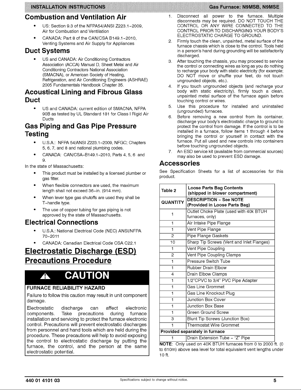
Accessories
See Specification Sheets for a list of accessories for this
product.
Table 2
QUANTITY
1
1 Air Intake Pipe Flange
1 Vent Pipe Flange
2 Pipe Flange Gaskets
10 Sharp Tip Screws (Vent and Inlet Flanges)
1 Vent Pipe Coupling
2 Vent Pipe Coupling Clamps
1 Pressure Switch Tube
1 Rubber Drain Elbow
4 Drain Elbow Clamps
1 1/2"CPVC to 3/4" PVC Pipe Adapter
1 Gas Line Grommet
1 Gas Line Knockout Plug
1 Junction Box Cover
1 Junction Box Base
1 Green Ground Screw
3 Blunt Tip Screws (Junction Box)
1 Thermostat Wire Grommet
Provided separately in furnace
1 Drain Extension Tube - "Z" Pipe
NOTE: Only used on 40K BTUH furnaces from 0 to 2000 ft. (0
to 610m) above sea level for total equivalent vent lengths under
lOft.
Loose Parts Bag Contents
(shipped in blower compartment)
DESCRIPTION - See NOTE
(Provided in Loose Parts Bag)
Outlet Choke Plate (used with 40k BTUH
furnaces, only)
440 01 4101 03 Specifications subject to change without notice. 5
Page 6
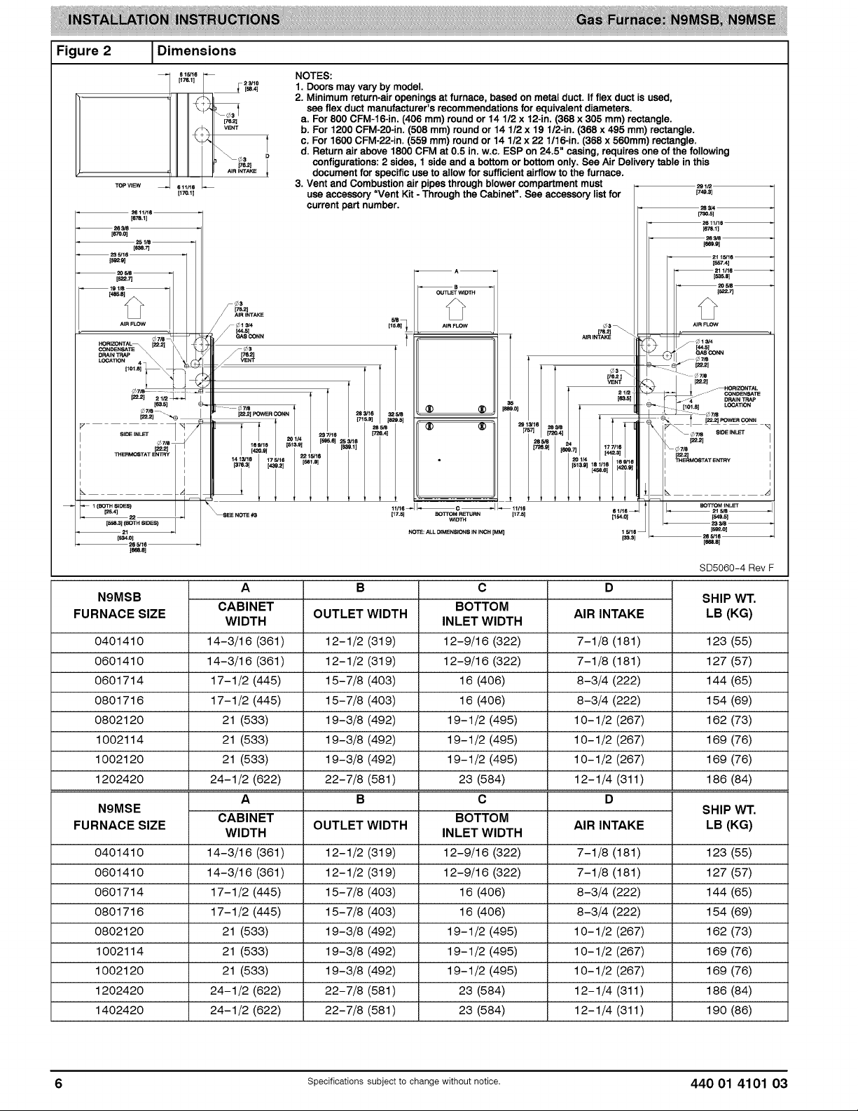
Figure 2 1Dimensions
s15/1
[17s.1]
[1/0,11
2_1o
_ [26,41
NOTES:
1. Doors may vary by model.
2. Minimum return-air openings at furnace, based on metal duct. If flex duct is used,
see flex duct manufacturer's recommendations for equivalent diameters.
a. For 800 CFM-16-in. (406 mm) round or 14 112 x 12-in. (368 x 305 mm) rectangle.
b. For 1200 CFM-20-in. (508 mm) round or 14 1/2 x 19 1/2-in. (368 x 495 mm) rectangle.
c. For 1600 CFM-22-in. (559 mm) round or 14 112x 22 1/16-in. (368 x 560mm) rectangle.
d. Return air above 1800 CFM at 0.5 in. w.c. ESP on 24.5" casing, requires one of the following
configurations: 2 sides, 1 side and a bottom or bottom only. See Air Delivery table in this
document for specific use to allow for sufficient airflow to the furnace.
3. Vent and Combustion air pipes through blower compartment must
use accessory Went Kit - Through the Cabinet". See accessory list for
current part number.
• 2611/16_
1749_1
283/4
[730,51
(_.11
1557,4]
[s26.e]
ls,_z.7]
[76.21 _\
AIR INTAKE
6 1116
[154.01
NOTE: ALL DIMENSIONS IN INCH [MM]
1268.8]
N9MSB
FURNACESIZE
0401410 12-1/2 (319) 7-1/8 (181) 123 (55)
0601410 12-1/2 (319) 7-1/8 (181) 127 (57)
0601714 15-7/8 (403) 8-3/4 (222) 144 (65)
0801716 15-7/8 (403) 8-3/4 (222) 154 (69)
0802120 19-3/8 (492) 10-1/2 (267) 162 (73)
1002114 19-3/8 (492) 10-1/2 (267) 169 (76)
1002120 19-3/8 (492) 10-1/2 (267) 169 (76)
1202420 22-7/8 (581) 12-1/4 (311 ) 186 (84)
N9MSE
FURNACESIZE
0401410 12-1/2 (319) 7-1/8 (181) 123 (55)
0601410 12-1/2 (319) 7-1/8 (181) 127 (57)
0601714 15-7/8 (403) 8-3/4 (222) 144 (65)
0801716 15-7/8 (403) 8-3/4 (222) 154 (69)
0802120 19-3/8 (492) 10-1/2 (267) 162 (73)
1002114 19-3/8 (492) 10-1/2 (267) 169 (76)
1002120 19-3/8 (492) 10-1/2 (267) 169 (76)
1202420 22-7/8 (581) 12-1/4 (311 ) 186 (84)
1402420 22-7/8 (581) 12-1/4 (311 ) 190 (86)
CABINET
WIDTH
14-3/16 (361)
14-3/16 (361)
17-1/2 (445)
17-1/2 (445)
21 (533)
21 (533)
21 (533)
24-1/2 (622)
A
CABINET
WIDTH
14-3/16 (361)
14-3/16 (361)
17-1/2 (445)
17-1/2 (445)
21 (533)
21 (533)
21 (533)
24-1/2 (622)
24-1/2 (622)
OUTLET WIDTH
OUTLET WIDTH AIR INTAKE
B
B D
C
BOTTOM
INLET WIDTH
12-9/16 (322)
12-9/16 (322)
16 (406)
16 (406)
19-1/2 (495)
19-1/2 (495)
19-1/2 (495)
23 (584)
C
BOTTOM
INLET WIDTH
12-9/16 (322)
12-9/16 (322)
16 (406)
16 (406)
19-1/2 (495)
19-1/2 (495)
19-1/2 (495)
23 (584)
23 (584)
AIR INTAKE
1 5/16
(_.31
DA
i_R FLOW
• ],
¢7/S
_[ J J-'- CONDENSATE
[101,61 LOCATION
J_ [22,2_ POWER CONN
_-- _ 7/8 SIDE INleT
_¢7/8
RMOSTAT ENTRY
GAS CONN
--_OR ZONTAL
_7/S
BOTTOM iNLET
215/8_
IS4_.S]
263/8 _
[51_.01
26 5/16
[_.e]
SD5060-4 Rev F
SHIP WT.
LB (KG)
SHIP WT.
LB (KG)
/
Specifications subject to change without notice. 440 01 4101 03
Page 7
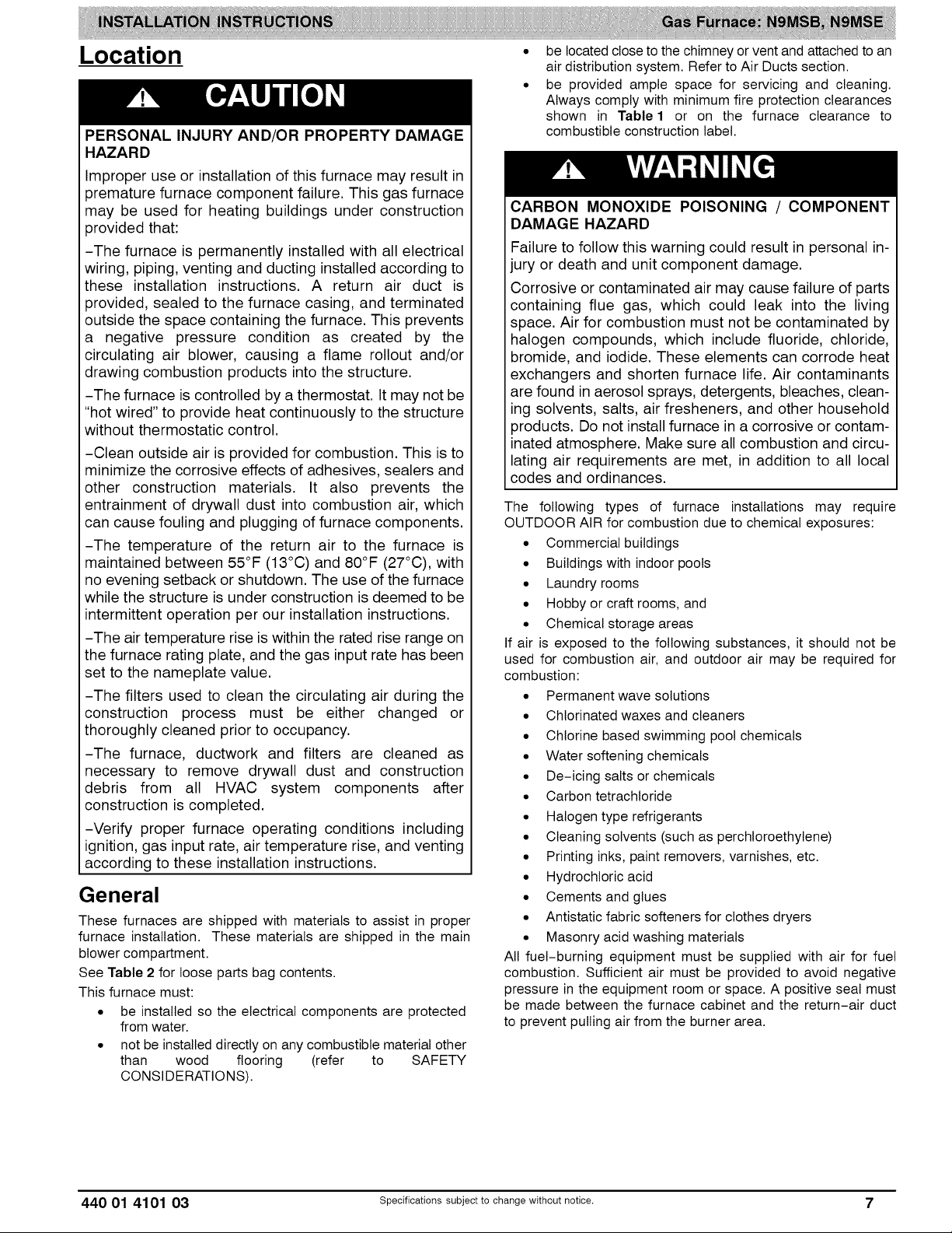
Location
PERSONAL INJURY AND/OR PROPERTY DAMAGE
HAZARD
Improper use or installation of this furnace may result in
3remature furnace component failure. This gas furnace
may be used for heating buildings under construction
3rovided that:
-The furnace is permanently installed with all electrical
wiring, piping, venting and ducting installed according to
these installation instructions. A return air duct is
3rovided, sealed to the furnace casing, and terminated
outside the space containing the furnace. This prevents
a negative pressure condition as created by the
circulating air blower, causing a flame rollout and/or
drawing combustion products into the structure.
-The furnace is controlled by a thermostat. It may not be
"hot wired" to provide heat continuously to the structure
without thermostatic control.
-Clean outside air is provided for combustion. This is to
minimize the corrosive effects of adhesives, sealers and
other construction materials. It also prevents the
entrainment of drywall dust into combustion air, which
can cause fouling and plugging of furnace components.
-The temperature of the return air to the furnace is
maintained between 55°F (13°C) and 80°F (27°C), with
no evening setback or shutdown. The use of the furnace
while the structure is under construction is deemed to be
intermittent operation per our installation instructions.
-The air temperature rise is within the rated rise range on
the furnace rating plate, and the gas input rate has been
set to the nameplate value.
-The filters used to clean the circulating air during the
construction process must be either changed or
thoroughly cleaned prior to occupancy.
-The furnace, ductwork and filters are cleaned as
necessary to remove drywall dust and construction
debris from all HVAC system components after
construction is completed.
-Verify proper furnace operating conditions including
ignition, gas input rate, air temperature rise, and venting
according to these installation instructions.
General
These furnaces are shipped with materials to assist in proper
furnace installation. These materials are shipped in the main
blower compartment.
See Table 2 for loose parts bag contents.
This furnace must:
• be installed so the electrical components are protected
from water.
• not be installed directly on any combustible material other
than wood flooring (refer to SAFETY
CONSIDERATIONS).
be located close to the chimney orvent and attached to an
air distribution system. Refer to Air Ducts section.
be provided ample space for servicing and cleaning.
Always comply with minimum fire protection clearances
shown in Table 1 or on the furnace clearance to
combustible construction label.
CARBON MONOXIDE POISONING / COMPONENT
DAMAGE HAZARD
Failure to follow this warning could result in personal in-
jury or death and unit component damage.
Corrosive or contaminated air may cause failure of parts
containing flue gas, which could leak into the living
space. Air for combustion must not be contaminated by
halogen compounds, which include fluoride, chloride,
bromide, and iodide. These elements can corrode heat
exchangers and shorten furnace life. Air contaminants
are found in aerosol sprays, detergents, bleaches, clean-
ing solvents, salts, air fresheners, and other household
products. Do not install furnace in a corrosive or contam-
inated atmosphere. Make sure all combustion and circu-
lating air requirements are met, in addition to all local
codes and ordinances.
The following types of furnace installations may require
OUTDOOR AIR for combustion due to chemical exposures:
• Commercial buildings
• Buildings with indoor pools
• Laundry rooms
• Hobby or craft rooms, and
• Chemical storage areas
If air is exposed to the following substances, it should not be
used for combustion air, and outdoor air may be required for
combustion:
• Permanent wave solutions
• Chlorinated waxes and cleaners
• Chlorine based swimming pool chemicals
• Water softening chemicals
• De-icing salts or chemicals
• Carbon tetrachloride
• Halogen type refrigerants
• Cleaning solvents (such as perchloroethylene)
• Printing inks, paint removers, varnishes, etc.
• Hydrochloric acid
• Cements and glues
• Antistatic fabric softeners for clothes dryers
• Masonry acid washing materials
All fuel-burning equipment must be supplied with air for fuel
combustion. Sufficient air must be provided to avoid negative
pressure in the equipment room or space. A positive seal must
be made between the furnace cabinet and the return-air duct
to prevent pulling air from the burner area.
440 01 4101 03 Specificationssubjectto change without notice. 7
Page 8
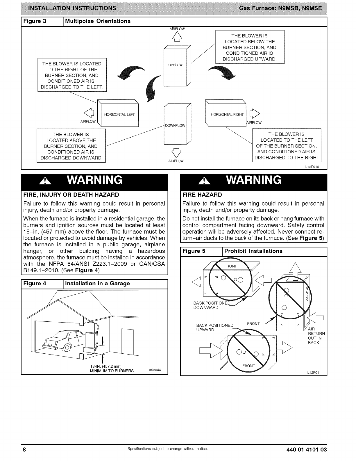
Figure 3 1Multipoise Orientations
THE BLOWER IS LOCATED
TO THE RIGHT OF THE
BURNER SECTION, AND
CONDITIONED AIR IS
DISCHARGED TO THE LEFT.
AIRFLOW
0
THE BLOWER IS
LOCATED BELOW THE
BURNER SECTION, AND
CONDITIONED AIR IS
DISCHARGED UPWARD.
I HORIZONTAL RIGHT1AIF F_LC w
THE BLOWER IS
LOCATED ABOVE THE
BURNER SECTION, AND
CONDITIONED AIR IS
DISCHARGED DOWNWARD. AIRFLOW
FIRE, INJURY OR DEATH HAZARD
Failure to follow this warning could result in personal
injury, death and/or property damage.
When the furnace is installed in a residential garage, the
burners and ignition sources must be located at least
18-in. (457 mm) above the floor. The furnace must be
located or protected to avoid damage by vehicles. When
the furnace is installed in a public garage, airplane
hangar, or other building having a hazardous
atmosphere, the furnace must be installed in accordance
with the NFPA 54/ANSI Z223.1-2009 or CAN/CSA
B149.1-2010. (See Figure 4)
Figure 4 1Installation in a Garage
THE BLOWER IS
LOCATED TO THE LEFT
OF THE BURNER SECTION,
AND CONDITIONED AIR IS
DISCHARGED TO THE RIGHT.
L12F010
FIRE HAZARD
Failure to follow this warning could result in personal
injury, death and/or property damage.
Do not install the furnace on its back or hang furnace with
control compartment facing downward. Safety control
operation will be adversely affected. Never connect re-
turn-air ducts to the back of the furnace. (See Figure 5)
Figure 5 _Prohibit Installations
BACK POSITIONED
DOWNWARD
BACK POSITIONED
UPWARD
18-1N. (457.2 mm)
MINIMUM TO BURNERS A93044
8 Specifications subject to change without notice. 440 01 4101 03
,d
IR
RETURN
CUT IN
BACK
L12F011
Page 9
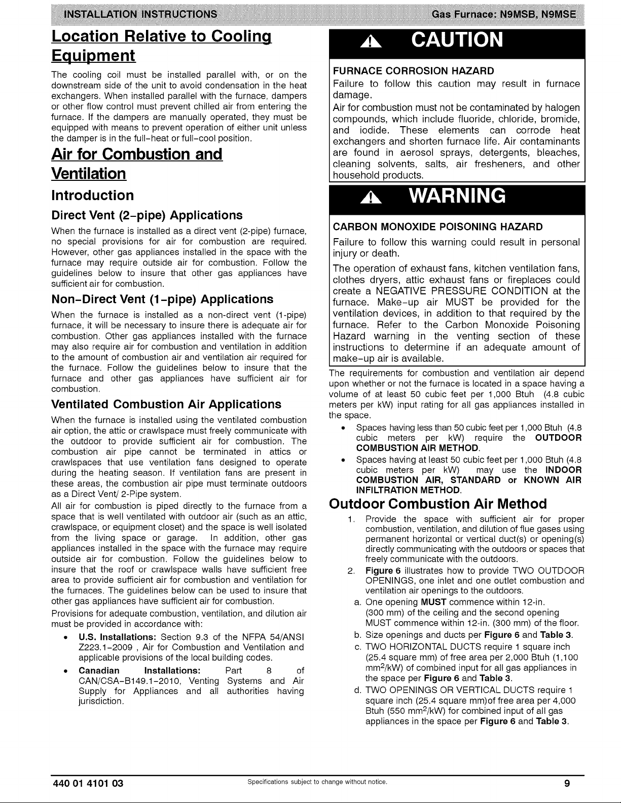
Location Relative to Cooling
Equipment
The cooling coil must be installed parallel with, or on the
downstream side of the unit to avoid condensation in the heat
exchangers. When installed parallel with the furnace, dampers
or other flow control must prevent chilled air from entering the
furnace. If the dampers are manually operated, they must be
equipped with means to prevent operation of either unit unless
the damper is in the full-heat or full-cool position.
Air for Combustion and
Ventilation
Introduction
FURNACE CORROSION HAZARD
Failure to follow this caution may result in furnace
damage.
Air for combustion must not be contaminated by halogen
compounds, which include fluoride, chloride, bromide,
and iodide. These elements can corrode heat
exchangers and shorten furnace life. Air contaminants
are found in aerosol sprays, detergents, bleaches,
cleaning solvents, salts, air fresheners, and other
household products.
Direct Vent (2-pipe) Applications
When the furnace is installed as a direct vent (2-pipe) furnace,
no special provisions for air for combustion are required.
However, other gas appliances installed in the space with the
furnace may require outside air for combustion. Follow the
guidelines below to insure that other gas appliances have
sufficient air for combustion.
Non-Direct Vent (1-pipe) Applications
When the furnace is installed as a non-direct vent (1-pipe)
furnace, it wilt be necessary to insure there is adequate air for
combustion. Other gas appliances installed with the furnace
may also require air for combustion and ventilation in addition
to the amount of combustion air and ventilation air required for
the furnace. Follow the guidelines below to insure that the
furnace and other gas appliances have sufficient air for
combustion.
Ventilated Combustion Air Applications
When the furnace is installed using the ventilated combustion
air option, the attic or crawlspace must freely communicate with
the outdoor to provide sufficient air for combustion. The
combustion air pipe cannot be terminated in attics or
crawlspaces that use ventilation fans designed to operate
during the heating season. If ventilation fans are present in
these areas, the combustion air pipe must terminate outdoors
as a Direct Vent/2-Pipe system.
All air for combustion is piped directly to the furnace from a
space that is well ventilated with outdoor air (such as an attic,
crawlspace, or equipment closet) and the space is well isolated
from the living space or garage. In addition, other gas
appliances installed in the space with the furnace may require
outside air for combustion. Follow the guidelines below to
insure that the roof or crawlspace walls have sufficient free
area to provide sufficient air for combustion and ventilation for
the furnaces. The guidelines below can be used to insure that
other gas appliances have sufficient air for combustion.
Provisions for adequate combustion, ventilation, and dilution air
must be provided in accordance with:
• U.S. Installations: Section 9.3 of the NFPA 54/ANSI
Z223.1-2009 , Air for Combustion and Ventilation and
applicable provisions of the local building codes.
• Canadian Installations: Part 8 of
CAN/CSA-B149.1-2010, Venting Systems and Air
Supply for Appliances and all authorities having
jurisdiction.
CARBON MONOXIDE POISONING HAZARD
Failure to follow this warning could result in personal
injury or death.
The operation of exhaust fans, kitchen ventilation fans,
clothes dryers, attic exhaust fans or fireplaces could
create a NEGATIVE PRESSURE CONDITION at the
furnace. Make-up air MUST be provided for the
ventilation devices, in addition to that required by the
furnace. Refer to the Carbon Monoxide Poisoning
Hazard warning in the venting section of these
instructions to determine if an adequate amount of
make-up air is available.
The requirements for combustion and ventilation air depend
upon whether or not the furnace is located in a space having a
volume of at least 50 cubic feet per 1,000 Btuh (4.8 cubic
meters per kW) input rating for all gas appliances installed in
the space.
• Spaces having less than 50 cubic feet per 1,000 Btuh (4.8
cubic meters per kW) require the OUTDOOR
COMBUSTION AIR METHOD.
• Spaces having at least 50 cubic feet per 1,000 Btuh (4.8
cubic meters per kW) may use the INDOOR
COMBUSTION AIR, STANDARD or KNOWN AIR
INFILTRATION METHOD.
Outdoor Combustion Air Method
1. Provide the space with sufficient air for proper
combustion, ventilation, and dilution of flue gases using
permanent horizontal or vertical duct(s) or opening(s)
directly communicating with the outdoors or spaces that
freely communicate with the outdoors.
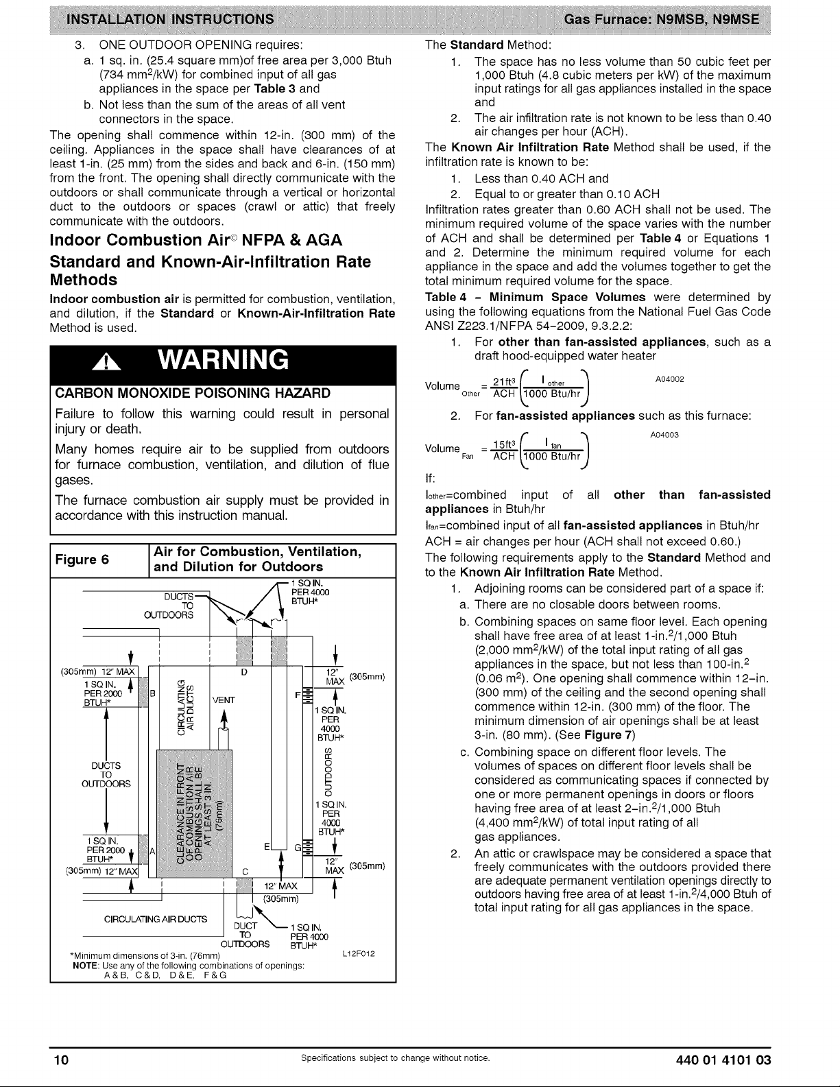
2. Figure 6 illustrates how to provide TWO OUTDOOR
OPENINGS, one inlet and one outlet combustion and
ventilation air openings to the outdoors.
a. One opening MUST commence within 12-in.
(300 mm) of the ceiling and the second opening
MUST commence within 12-in. (300 mm) of the floor.
b. Size openings and ducts per Figure 6 and Table 3.
c. TWO HORIZONTAL DUCTS require 1 square inch
(25.4 square mm) of free area per 2,000 Btuh (1,100
mm2/kW) of combined input for all gas appliances in
the space per Figure 6 and Table 3.
d. TWO OPENINGS OR VERTICAL DUCTS require 1
square inch (25.4 square mm)of free area per 4,000
Btuh (550 mm2/kW) for combined input of all gas
appliances in the space per Figure 6 and Table 3.
440 01 4101 03 Specificationssubjectto change without notice. 9
Page 10
3. ONE OUTDOOR OPENING requires:
a. 1 sq. in. (25.4 square mm)of free area per 3,000 Btuh
(734 mm2/kW) for combined input of all gas
appliances in the space per Table 3 and
b. Not less than the sum of the areas of all vent
connectors in the space.
The opening shall commence within 12-in. (300 mm) of the
ceiling. Appliances in the space shall have clearances of at
least 1-in. (25 mm) from the sides and back and 6-in. (150 mm)
from the front. The opening shall directly communicate with the
outdoors or shall communicate through a vertical or horizontal
duct to the outdoors or spaces (crawl or attic) that freely
communicate with the outdoors.
Indoor Combustion Air ° NFPA & AGA
Standard and Known-Air-Infiltration Rate
Methods
Indoor combustion air is permitted for combustion, ventilation,
and dilution, if the Standard or Known-Air-Infiltration Rate
Method is used.
The Standard Method:
1. The space has no less volume than 50 cubic feet per
1,000 Btuh (4.8 cubic meters per kW) of the maximum
input ratings for alt gas appliances installed in the space
and
2. The air infiltration rate is not known to be less than 0.40
air changes per hour (ACH).
The Known Air Infiltration Rate Method shall be used, if the
infiltration rate is known to be:
1. Less than 0.40 ACH and
2. Equal to or greater than 0.10 ACH
Infiltration rates greater than 0.60 ACH shall not be used. The
minimum required volume of the space varies with the number
of ACH and shall be determined per Table 4 or Equations 1
and 2. Determine the minimum required volume for each
appliance in the space and add the volumes together to get the
total minimum required volume for the space.
Table 4 - Minimum Space Volumes were determined by
using the following equations from the National Fuel Gas Code
ANSI Z223.1/NFPA 54-2009, 9.3.2.2:
1. For other than fan-assisted appliances, such as a
draft hood-equipped water heater
CARBON MONOXIDE POISONING HAZARD
Failure to follow this warning could result in personal
injury or death.
Many homes require air to be supplied from outdoors
for furnace combustion, ventilation, and dilution of flue
gases.
The furnace combustion air supply must be provided in
accordance with this instruction manual.
Figure 6
(305_m/12"M_X]j
lsQiN, ill
PER 2000 B
BTUH*
and Dilution for Outdoors
JAir for Combustion, Ventilation,
DUCTS ,
-k /l E 40o0
TO BTUH
OUiDOORS
' J :i
VENT
1 SQ IN.
12/_X (305ram}
1 so IN.
PER
4000
BTUH*
b3
n-
O
O
/
f
t
£
o
SQ IN.
PER
4000
sa i .
PER 2000 A
(305mm)12"MAN | I
CIRCULATING AIR DUCTS
*Minimum dimensions of 3-in. (76mm)
NOTE: Use any of the following combinations of openings:
A&B, C&D, D&E, F&G
' 1
I
OUTDOORS BTUH*
12" MAX
(305mm)
TO PER 4000
BTUH*
_2j_X (a05mm)
I SQ IN,
L12F012
Volume _ 21ft 3 _ I other "_ A04002
Other ACH _.000 Btu/hrJ
2. For fan-assisted appliances such as this furnace:
_ 15ft3 I fan
VolumeFan ACH 000 Btu/hr
( ) o40o
If:
Iother=combJned input of all other than fan-assisted
appliances in Btuh/hr
Ifan=combined input of all fan-assisted appliances in Btuh/hr
ACH = air changes per hour (ACH shall not exceed 0.60.)
The following requirements apply to the Standard Method and
to the Known Air Infiltration Rate Method.
1. Adjoining rooms can be considered part of a space if:
a. There are no closable doors between rooms.
b. Combining spaces on same floor level. Each opening
shall have free area of at least 1-in.2/1,000 Btuh
(2,000 mm2/kW) of the total input rating of all gas
appliances in the space, but not less than 100-in. 2
(0.06 m2). One opening shall commence within 12-in.
(300 mm) of the ceiling and the second opening shall
commence within 12-in. (300 mm) of the floor. The
minimum dimension of air openings shall be at least
3-in. (80 mm). (See Figure 7)
c. Combining space on different floor levels. The
volumes of spaces on different floor levels shall be
considered as communicating spaces if connected by
one or more permanent openings in doors or floors
having free area of at least 2-in.2/1,000 Btuh
(4,400 mm2/kW) of total input rating of all
gas appliances.
2. An attic or crawlspace may be considered a space that
freely communicates with the outdoors provided there
are adequate permanent ventilation openings directly to
outdoors having free area of at least 1-in.2/4,000 Btuh of
total input rating for all gas appliances in the space.
10 Specificationssubjectto change without notice. 440 01 4101 03
Page 11
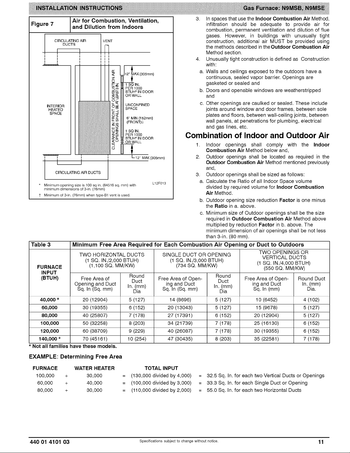
Airfor Combustion,Ventilation,
Figure7 andDilutionfromIndoors
CIRCULATING AIR VENT
DUCTS
I
I
I
I I I I
I I I I
I I I I
_(305mm)
3. In spaces that use the Indoor Combustion Air Method,
infiltration should be adequate to provide air for
combustion, permanent ventilation and dilution of flue
gases. However, in buildings with unusually tight
construction, additional air MUST be provided using
the methods described in the Outdoor Combustion Air
Method section.
4. Unusually tight construction is defined as Construction
with:
a. Walls and ceilings exposed to the outdoors have a
continuous, sealed vapor barrier. Openings are
E_ ----t SQIN.
_" _o = PER 1000
_: _ BTUH* IN DOOR
_ ORWALL
INTERIOR
HEATED
SPACE
i C_ UNCONFINED
rr T 6" MIN (152ram)
u_ o0 (FRONT)0
z_
tSO,N.
zZ PER 1000
g O___&_ALL
I
I
CIRCULATING AIR DUCTS
* Minimum opening size is 100 sq in, (64516 sq, mm) with
minimum dimensions of 3-in, (76mm)
1 Minimum of 3-in, (76mm) when type-B1 vent is used,
HHHHHHHHHHHHHHHHHHHHHHHHHHHHHHHHHHHHHHHHHHHHHHHHHHHHHHHH
i i - 12" MAX (3O5mm)
I
o
Combination of Indoor and Outdoor Air
Lt2F013
gasketed or sealed and
b. Doors and openable windows are weatherstripped
and
c. Other openings are caulked or sealed. These include
joints around window and door frames, between sole
plates and floors, between walt-ceiling joints, between
wall panels, at penetrations for plumbing, electrical
and gas lines, etc.
1.
Indoor openings shall comply with the Indoor
Combustion Air Method below and,
2.
Outdoor openings shall be located as required in the
Outdoor Combustion Air Method mentioned previously
and,
3.
Outdoor openings shall be sized as follows:
a.
Calculate the Ratio of all Indoor Space volume
divided by required volume for Indoor Combustion
Air Method.
b.
Outdoor opening size reduction Factor is one minus
the Ratio in a. above.
C.
Minimum size of Outdoor openings shall be the size
required in Outdoor Combustion Air Method above
multiplied by reduction Factor in b. above. The
minimum dimension of air openings shall be not less
than 3-in. (80 mm).
Table 3 Minimum Free Area Required for Each Combustion Air Opening or Duct to Outdoors
TWO HORIZONTAL DUCTS SINGLE DUCT OR OPENING TWO OPENINGS OR
(1 SQ. IN./2,000 BTUH) (1 SQ. IN./3,000 BTUH)
FURNACE (1,100 SQ. MM/KW) (734 SQ. MM/KW) (1 SQ. IN./4,000 BTUH)
INPUT
Round Round
VERTICAL DUCTS
(550 SQ. MM/KW)
(BTUH) Free Area of Duct Free Area of Open- Duct Free Area of Open- Round Duct
Opening and Duct In. (mm) ing and Duct In. (mm) ing and Duct In. (mm)
Sq. In (Sq. mm) Dia Sq. In (Sq. mm) Dia Sq. In (mm) Dia.
40,000 * 20 (12904) 5 (127) 14 (8696) 5 (127) 10 (6452) 4 (102)
60,000 30 (19355) 6 (152) 20 (13043) 5 (127) 15 (9678) 5 (127)
80,000 40 (25807) 7 (178) 27 (17391) 6 (152) 20 (12904) 5 (127)
100,000 50 (32258) 8 (203) 34 (21739) 7 (178) 25 (16130) 6 (152)
120,000 60 (38709) 9 (229) 40 (26087) 7 (178) 30 (19355) 6 (152)
140,000 * 70 (45161) 10 (254) 47 (30435) 8 (203) 35 (22581) 7 (178)
• Not all families have these models,
EXAMPLE: Determining Free Area
FURNACE WATER HEATER TOTAL INPUT
100,000 + 30,000 = (130,000 divided by 4,000)
60,000 + 40,000 = (100,000 divided by 3,000)
80,000 + 30,000 = (110,000 divided by 2,000)
440 01 4101 03 specificationssubjectto change without notice. 11
= 32.5 Sq. In. for each two Vertical Ducts or Openings
= 33.3 Sq. In. for each Single Duct or Opening
= 55.0 Sq. In. for each two Horizontal Ducts
Page 12
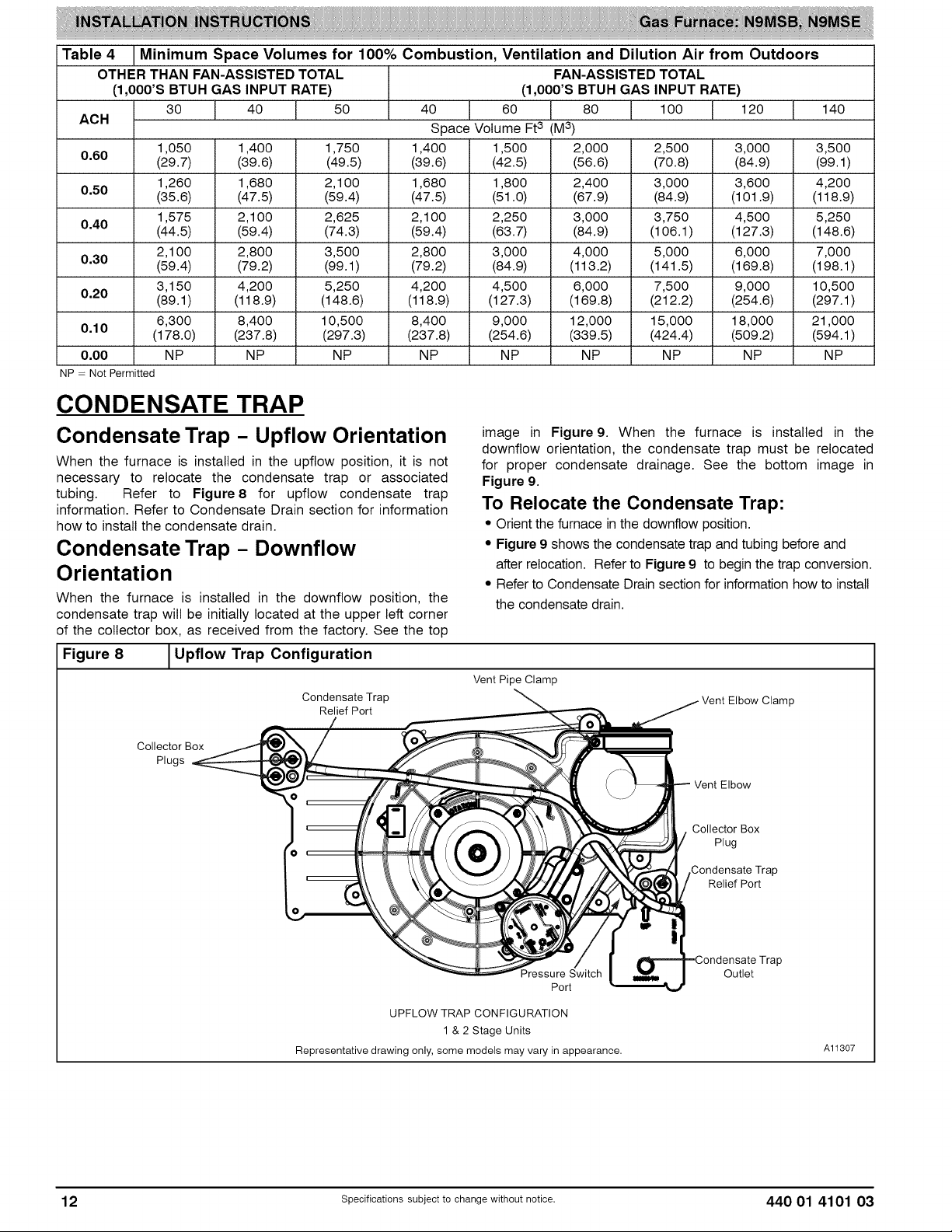
Table 4 Minimum Space Volumes for 100% Combustion, Ventilation and Dilution Air from Outdoors
OTHER THAN FAN-ASSISTED TOTAL FAN-ASSISTED TOTAL
(1,000'S BTUH GAS INPUT RATE) (1,000'S BTUH GAS INPUT RATE)
30 40 50 40 60 80 1O0 120 140
AOH Space Volume Ft3 (U 3)
1,050 1,400 1,750 1,400 1,500 2,000 2,500 3,000 3,500
0.60 (29.7) (39.6) (49.5) (39.6) (42.5) (56.6) (70.8) (84.9) (99.1)
1,260 1,680 2,1 O0 1,680 1,800 2,400 3,000 3,600 4,200
0.50 (35.6) (47.5) (59.4) (47.5) (51.0) (67.9) (84.9) (101.9) (118.9)
1,575 2,1 O0 2,625 2,1 O0 2,250 3,000 3,750 4,500 5,250
0.40 (44.5) (59.4) (74.3) (59.4) (63.7) (84.9) (106.1 ) (127.3) (148.6)
2,1 O0 2,800 3,500 2,800 3,000 4,000 5,000 6,000 7,000
0.30 (59.4) (79.2) (99.1) (79.2) (84.9) (113.2) (141.5) (169.8) (198.1 )
3,150 4,200 5,250 4,200 4,500 6,000 7,500 9,000 10,500
0.20 (89.1) (118.9) (148.6) (118.9) (127.3) (169.8) (212.2) (254.6) (297.1)
6,300 8,400 10,500 8,400 9,000 12,000 15,000 18,000 21,000
0.10 (178.0) (237.8) (297.3) (237.8) (254.6) (339.5) (424.4) (509.2) (594.1)
0,00 NP NP NP NP NP NP NP NP NP
NP = Not Permitted
CONDENSATE TRAP
Condensate Trap - Upflow Orientation
When the furnace is installed in the upflow position, it is not
necessary to relocate the condensate trap or associated
tubing. Refer to Figure8 for upflow condensate trap
information. Refer to Condensate Drain section for information
how to install the condensate drain.
Condensate Trap - Downflow
Orientation
When the furnace is installed in the downflow position, the
condensate trap will be initially located at the upper left corner
of the collector box, as received from the factory. See the top
Figure 8 _Upflow Trap Configuration
I
Condensate Trap
Relief Port
Collector Box
Plugs
image in Figure9. When the furnace is installed in the
downflow orientation, the condensate trap must be relocated
for proper condensate drainage. See the bottom image in
Figure 9.
To Relocate the Condensate Trap:
• Orient the furnace in the downflow position.
• Figure 9 shows the condensate trap and tubing before and
after relocation. Refer to Figure 9 to begin the trap conversion.
• Refer to Condensate Drain section for information how to install
the condensate drain.
Vent Pipe Clamp
Vent Elbow Clamp
Vent Elbow
Collector Box
Plug
Condensate Trap
Relief Port
Pressure Switch
Port
UPFLOW TRAP CONFIGURATION
1 & 2 Stage Units
Representative drawing only, some models may vary in appearance.
Outlet
Al1307
12 specificationssubjectto change without notice. 440 01 4101 03
Page 13
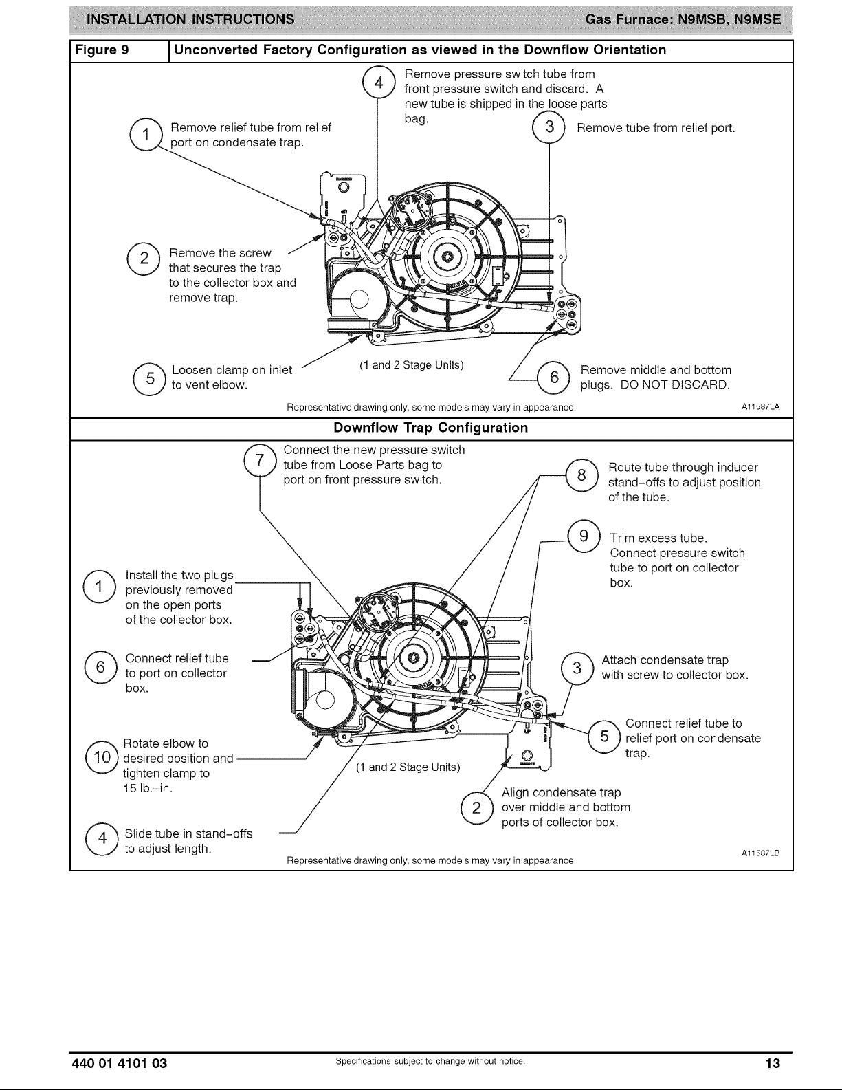
Figure 9
Unconverted Factory Configuration as viewed in the Downflow Orientation
Remove pressure switch tube from
front pressure switch and discard. A
new tube is shipped in the loose parts
Remove tube from relief port.
tief
(_ emovethe screw /
that secures the trap
to the collector box and
remove trap.
(_ Loosen clamp on inlet (1 and 2 Stage Units) Remove middle and bottom
to vent elbow, plugs. DO NOT DISCARD.
Representative drawing only, some models may vary in appearance. A11587LA
Downflow Trap Configuration
Connect the new pressure switch
tube from Loose Parts bag to _ Route tube through inducer
port on front pressure switch. _ stand-offs to adjust position
?
i
(_ nstall the two plugs
previously removed
on the open ports
of the collector box.
(_) Connect relief tube
to port on collector
box.
desired position and
(_ Rotate elbow to
tighten clamp to
15 lb.-in.
(_ Slide tube in stand-offs
to adjust length.
/ of the tube.
/ / r___-k N ) Trim excess tube.
/ / / X"-J Connect Pressure switch
/ / / tube to port on collector
.,,,_ _,, ' / t box.
I__i _ (/_ Attach condensate trap
_,,\VV___ _,_ I,_ If====/II \ _ ) with screw to collector box.
_ ___----- _ relief port on condensate
/ trap.
(1 and 2 Stage Units)
/_= Align condensate trap
ports of collector box.
Representative drawing only, some models may vary in appearance.
A11587LB
440 01 4101 03 specificationssubjectto change without notice. 13
Page 14
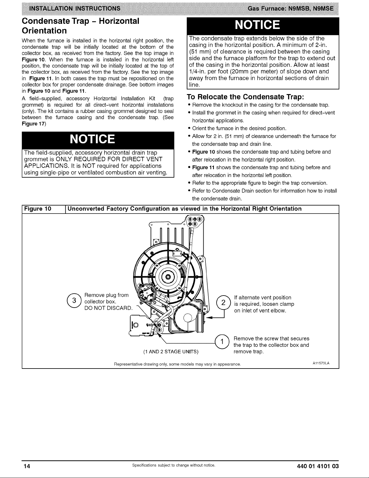
Condensate Trap - Horizontal
Orientation
When the furnace is installed in the horizontal right position, the
condensate trap will be initially located at the bottom of the
collector box, as received from the factory. See the top image in
Figure10. When the furnace is installed in the horizontal left
position, the condensate trap will be initially located at the top of
the collector box, as received from the factory. See the top image
in Figure 11. In both cases the trap must be repositioned on the
collector box for proper condensate drainage. See bottom images
in Figure 10 and Figure 11.
A field-supplied, accessory Horizontal Installation Kit (trap
grommet) is required for all direct-vent horizontal installations
(only). The kit contains a rubber casing grommet designed to seal
between the furnace casing and the condensate trap. (See
Figure 17)
The field-supplied, accessory horizontal drain trap
grommet is ONLY REQUIRED FOR DIRECT VENT
APPLICATIONS. It is NOT required for applications
using single-pipe or ventilated combustion air venting.
The condensate trap extends below the side of the
casing in the horizontal position. A minimum of 2-in.
(51 mm) of clearance is required between the casing
side and the furnace platform for the trap to extend out
of the casing in the horizontal position. Allow at least
1/4-in. per foot (20mm per meter) of slope down and
away from the furnace in horizontal sections of drain
line.
To Relocate the Condensate Trap:
• Remove the knockout in the casing for the condensate trap.
• Install the grommet in the casing when required for direct-vent
horizontal applications.
• Orient the furnace in the desired position.
• Allow for 2 in. (51 mm) of clearance underneath the furnace for
the condensate trap and drain line.
• Figure 10 shows the condensate trap and tubing before and
after relocation in the horizontal right position.
• Figure 11 shows the condensate trap and tubing before and
after relocation in the horizontal left position.
• Refer to the appropriate figure to begin the trap conversion.
• Refer to Condensate Drain section for information how to install
the condensate drain.
Figure 10 1Unconverted Factory Configuration as viewed in the Horizontal Right Orientation
collector box.
(_ emove plug from
DO NOT DISCARD.
Representative drawing only, some models may vary in appearance.
(1 AND 2 STAGE UNITS)
If alternate vent position
is required, loosen clamp
on inlet of vent elbow.
Remove the screw that secures
the trap to the collector box and
remove trap.
A11573LA
14 Specificationssubjectto change without notice. 440 01 4101 03
Page 15
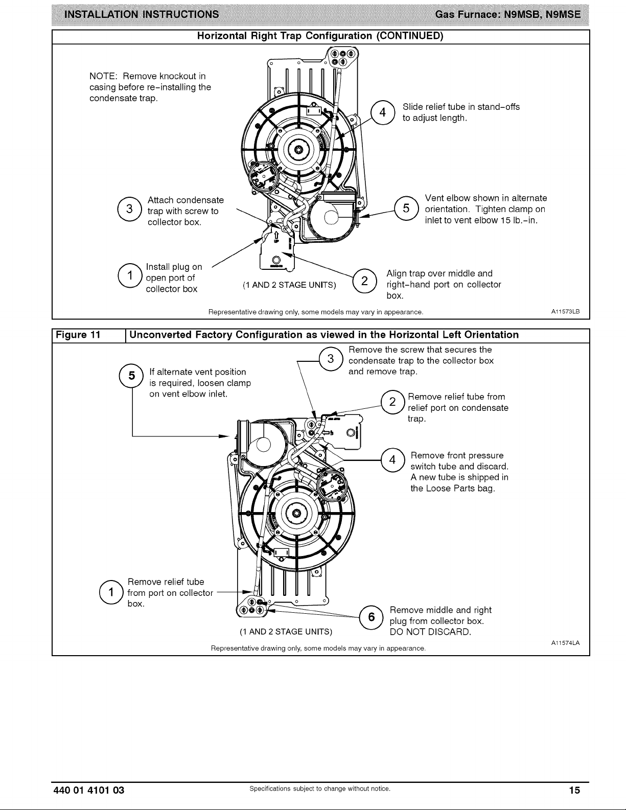
HorizontalRightTrapConfiguration(CONTINUED)
NOTE: Remove knockout in
casing before re-installing the
condensate trap.
trap with screw to
(_ ttach condensate
collector box.
open port of Align trap over middle and
(_ Install plug on
collector box (1 AND 2 STAGE UNITS) right-hand port on collector
Slide relief tube in stand-offs
to adjust length.
box.
Representative drawing only, some models may vary in appearance.
Vent elbow shown in alternate
orientation. Tighten clamp on
inlet to vent elbow 15 lb.-in.
A11573LB
Figure 11
Unconverted Factory Configuration as viewed in the Horizontal Left Orientation
If alternate vent position
is required, loosen clamp
on vent elbow inlet.
from port on collector --
(_ emove relief tube
box.
Remove the screw that secures the
condensate trap to the collector box
and remove trap.
Remove relief tube from
relief port on condensate
trap.
Remove front pressure
switch tube and discard.
A new tube is shipped in
the Loose Parts bag.
Remove middle and right
plug from collector box.
(1 AND 2 STAGE UNITS)
Representative drawing only, some models may vary in appearance.
DO NOT DISCARD.
A11574LA
440 01 4101 03 specificationssubjectto change without notice. 15
Page 16
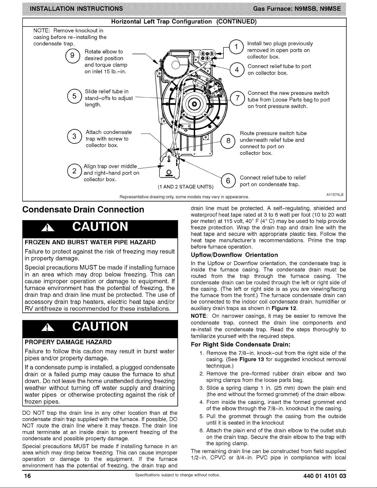
NOTE: Remove knockout in
casing before re-installing the
condensate trap.
(_ otate elbow to
desired position
and torque clamp
on inlet 15 lb.-in.
Horizontal Left Trap Configuration (CONTINUED)
Install two plugs previously
removed in open ports on
collector box.
Connect relief tube to port
on collector box.
(_ Slide relief tube instand-offs to adjust
length.
(_ Attach condensatetrap with screw to
collector box.
(_ Align trap over middle
and right-hand port on
collector box.
(1 AND 2 STAGE UNITS)
Representative drawing only, some models may vary in appearance.
Condensate Drain Connection
FROZEN AND BURST WATER PIPE HAZARD
Failure to protect against the risk of freezing may result
in property damage.
Special precautions MUST be made if installing furnace
in an area which may drop below freezing. This can
cause improper operation or damage to equipment. If
furnace environment has the potential of freezing, the
drain trap and drain line must be protected. The use of
accessory drain trap heaters, electric heat tape and/or
RV antifreeze is recommended for these installations.
PROPERY DAMAGE HAZARD
Failure to follow this caution may result in burst water
pipes and/or property damage.
If a condensate pump is installed, a plugged condensate
drain or a failed pump may cause the furnace to shut
down. Do not leave the home unattended during freezing
weather without turning off water supply and draining
water pipes or otherwise protecting against the risk of
frozen pipes.
DO NOT trap the drain line in any other location than at the
condensate drain trap supplied with the furnace. If possible, DO
NOT route the drain line where it may freeze. The drain line
must terminate at an inside drain to prevent freezing of the
condensate and possible property damage.
Special precautions MUST be made if installing furnace in an
area which may drop below freezing. This can cause improper
operation or damage to the equipment. If the furnace
environment has the potential of freezing, the drain trap and
drain line must be protected. A self-regulating, shielded and
waterproof heat tape rated at 3 to 6 watt per foot (10 to 20 watt
per meter) at 115 volt, 40° F (4° C) may be used to help provide
freeze protection. Wrap the drain trap and drain line with the
heat tape and secure with appropriate plastic ties. Follow the
heat tape manufacturer's recommendations. Prime the trap
before furnace operation.
Upflow/Downflow Orientation
In the Upflow or Downflow orientation, the condensate trap is
inside the furnace casing. The condensate drain must be
routed from the trap through the furnace casing. The
condensate drain can be routed through the left or right side of
the casing. (The left or right side is as you are viewing/facing
the furnace from the front.) The furnace condensate drain can
be connected to the indoor coil condensate drain, humidifier or
auxiliary drain traps as shown in Figure 12.
NOTE: On narrower casings, it may be easier to remove the
condensate trap, connect the drain line components and
re-install the condensate trap. Read the steps thoroughly to
familiarize yourself with the required steps.
For Right Side Condensate Drain:
1. Remove the 7/8-in. knock-out from the right side of the
casing. (See Figure 13 for suggested knockout removal
technique.)
2. Remove the pre-formed rubber drain elbow and two
spring clamps from the loose parts bag.
3. Slide a spring clamp 1 in. (25 mm) down the plain end
(the end without the formed grommet) of the drain elbow.
4. From inside the casing, insert the formed grommet end
of the elbow through the 7/8-in. knockout in the casing.
5. Pull the grommet through the casing from the outside
until it is seated in the knockout
6. Attach the plain end of the drain elbow to the outlet stub
on the drain trap. Secure the drain elbow to the trap with
the spring clamp.
The remaining drain line can be constructed from field supplied
1/2-in. CPVC or 3/4-in. PVC pipe in compliance with local
Connect the new pressure switch
tube from Loose Parts bag to port
on front pressure switch.
Route pressure switch tube
underneath relief tube and
connect to port on
collector box.
Connect relief tube to relief
port on condensate trap.
A11574LB
16 Specificationssubjectto change without notice. 440 01 4101 03
Page 17
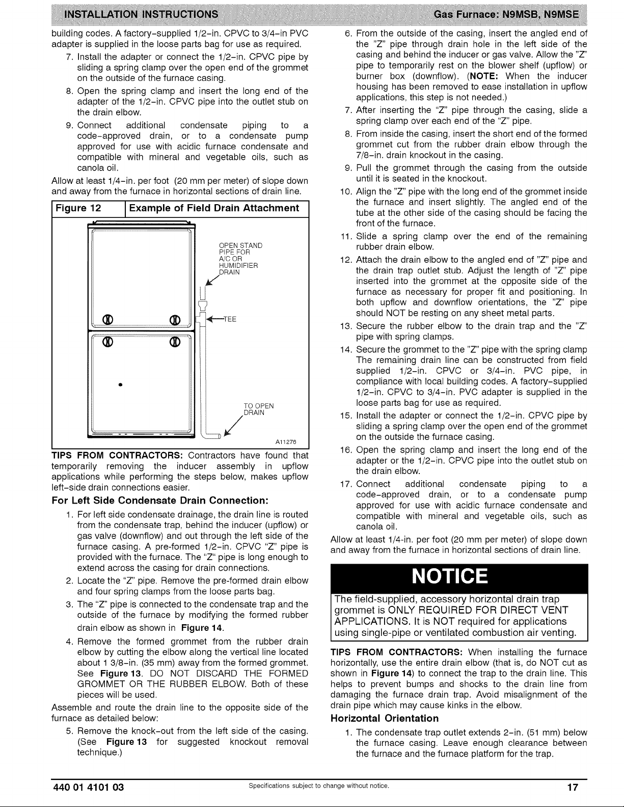
building codes. A factory-supplied 1/2-in. CPVC to 3/4-in PVC
adapter is supplied in the loose parts bag for use as required.
7. Install the adapter or connect the 1/2-in. CPVC pipe by
sliding a spring clamp over the open end of the grommet
on the outside of the furnace casing.
8. Open the spring clamp and insert the long end of the
adapter of the 1/2-in. CPVC pipe into the outlet stub on
the drain elbow.
9. Connect additional condensate piping to a
code-approved drain, or to a condensate pump
approved for use with acidic furnace condensate and
compatible with mineral and vegetable oils, such as
canola oil.
Allow at least 1/4-in. per foot (20 mm per meter) of slope down
and away from the furnace in horizontal sections of drain line.
Figure 12 _Example of Field Drain Attachment
OPEN STAND
PIPE FOR
A/C OR
HUMIDIFIER
DRAIN
U
i-,_--TEE
TO OPEN
DRAIN
Al1276
TIPS FROM CONTRACTORS: Contractors have found that
temporarily removing the inducer assembly in upflow
applications while performing the steps below, makes upflow
left-side drain connections easier.
For Left Side Condensate Drain Connection:
1. For left side condensate drainage, the drain line is routed
from the condensate trap, behind the inducer (upflow) or
gas valve (downflow) and out through the left side of the
furnace casing. A pre-formed 1/2-in. CPVC "Z" pipe is
provided with the furnace. The "Z" pipe is long enough to
extend across the casing for drain connections.
2. Locate the "Z" pipe. Remove the pre-formed drain elbow
and four spring clamps from the loose parts bag.
3. The "Z" pipe is connected to the condensate trap and the
outside of the furnace by modifying the formed rubber
drain elbow as shown in Figure 14.
4. Remove the formed grommet from the rubber drain
elbow by cutting the elbow along the vertical line located
about 1 3/8-in. (35 mm) away from the formed grommet.
See Figure13. DO NOT DISCARD THE FORMED
GROMMET OR THE RUBBER ELBOW. Both of these
pieces will be used.
Assemble and route the drain line to the opposite side of the
furnace as detailed below:
5. Remove the knock-out from the left side of the casing.
(See Figure 13 for suggested knockout removal
technique.)
6. From the outside of the casing, insert the angled end of
the "Z" pipe through drain hole in the left side of the
casing and behind the inducer or gas valve. Allow the "Z"
pipe to temporarily rest on the blower shelf (upflow) or
burner box (downflow). (NOTE: When the inducer
housing has been removed to ease installation in upflow
applications, this step is not needed.)
7. After inserting the "Z" pipe through the casing, slide a
spring clamp over each end of the "Z" pipe.
8. From inside the casing, insert the short end of the formed
grommet cut from the rubber drain elbow through the
7/8-in. drain knockout in the casing.
9. Pull the grommet through the casing from the outside
until it is seated in the knockout.
10. Align the "Z" pipe with the long end of the grommet inside
the furnace and insert slightly. The angled end of the
tube at the other side of the casing should be facing the
front of the furnace.
11. Slide a spring clamp over the end of the remaining
rubber drain elbow.
12. Attach the drain elbow to the angled end of "Z" pipe and
the drain trap outlet stub. Adjust the length of "Z" pipe
inserted into the grommet at the opposite side of the
furnace as necessary for proper fit and positioning. In
both upflow and downflow orientations, the "Z" pipe
should NOT be resting on any sheet metal parts.
13. Secure the rubber elbow to the drain trap and the "Z"
pipe with spring clamps.
14. Secure the grommet to the "Z" pipe with the spring clamp
The remaining drain line can be constructed from field
supplied 1/2-in. CPVC or 3/4-in. PVC pipe, in
compliance with local building codes. A factory-supplied
1/2-in. CPVC to 3/4-in. PVC adapter is supplied in the
loose parts bag for use as required.
15. Install the adapter or connect the 1/2-in. CPVC pipe by
sliding a spring clamp over the open end of the grommet
on the outside the furnace casing.
16. Open the spring clamp and insert the long end of the
adapter or the 1/2-in. CPVC pipe into the outlet stub on
the drain elbow.
17. Connect additional condensate piping to a
code-approved drain, or to a condensate pump
approved for use with acidic furnace condensate and
compatible with mineral and vegetable oils, such as
canola oil.
Allow at least 1/4-in. per foot (20 mm per meter) of slope down
and away from the furnace in horizontal sections of drain line.
The field-supplied, accessory horizontal drain trap
grommet is ONLY REQUIRED FOR DIRECT VENT
APPLICATIONS, It is NOT required for applications
using single-pipe or ventilated combustion air venting.
TIPS FROM CONTRACTORS: When installing the furnace
horizontally, use the entire drain elbow (that is, do NOT cut as
shown in Figure 14) to connect the trap to the drain line. This
helps to prevent bumps and shocks to the drain line from
damaging the furnace drain trap. Avoid misatignment of the
drain pipe which may cause kinks in the elbow.
Horizontal Orientation
1. The condensate trap outlet extends 2-in. (51 mm) below
the furnace casing. Leave enough clearance between
the furnace and the furnace platform for the trap.
440 01 4101 03 Specificationssubjectto change without notice. 17
Page 18
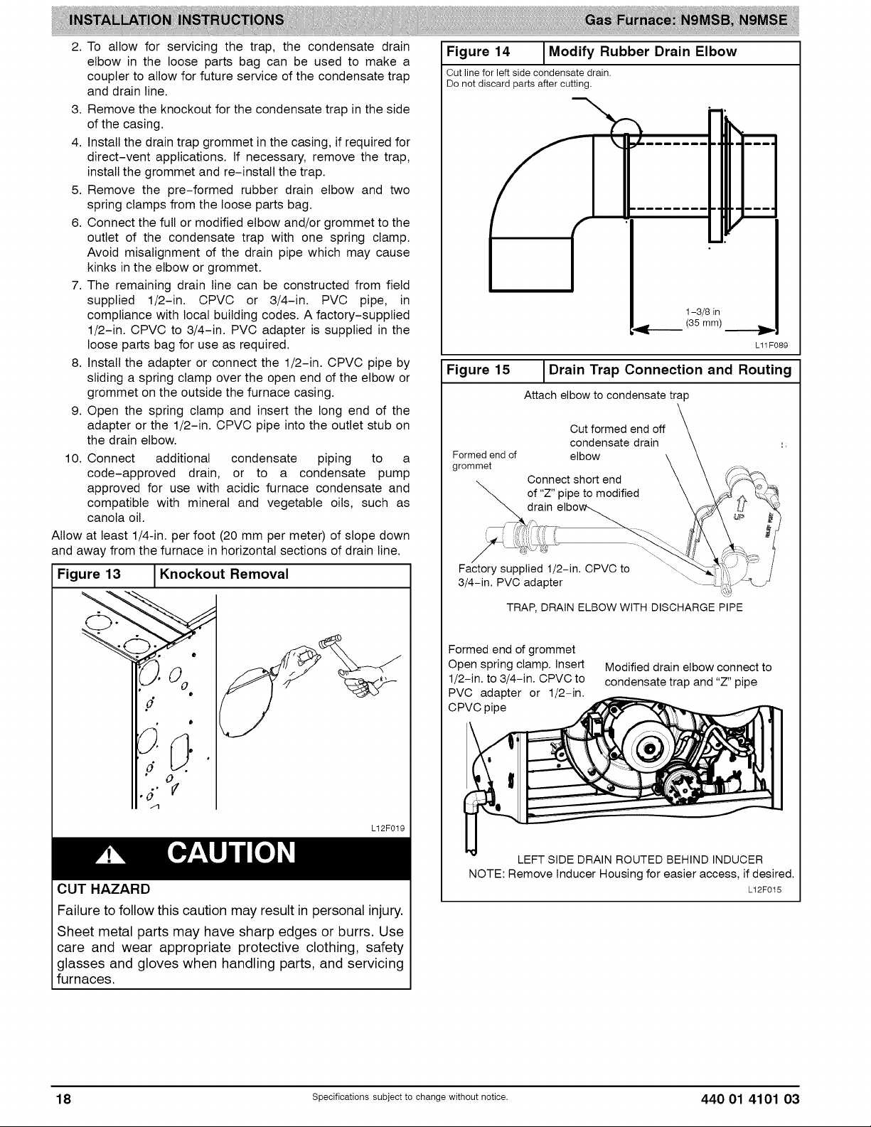
2. To allow for servicing the trap, the condensate drain
elbow in the loose parts bag can be used to make a
coupler to allow for future service of the condensate trap
and drain line.
3. Remove the knockout for the condensate trap in the side
of the casing.
4. Install the drain trap grommet in the casing, if required for
direct-vent applications. If necessary, remove the trap,
install the grommet and re-install the trap.
5. Remove the pre-formed rubber drain elbow and two
spring clamps from the loose parts bag.
6. Connect the full or modified elbow and/or grommet to the
outlet of the condensate trap with one spring clamp.
Avoid misalignment of the drain pipe which may cause
kinks inthe elbow or grommet.
7. The remaining drain line can be constructed from field
supplied 1/2-in. CPVC or 3/4-in. PVC pipe, in
compliance with local building codes. A factory-supplied
1/2-in. CPVC to 3/4-in. PVC adapter is supplied in the
loose parts bag for use as required.
8. Install the adapter or connect the 1/2-in. CPVC pipe by
sliding a spring clamp over the open end of the elbow or
grommet on the outside the furnace casing.
9. Open the spring clamp and insert the long end of the
adapter or the 1/2-in. CPVC pipe into the outlet stub on
the drain elbow.
10. Connect additional condensate piping to a
code-approved drain, or to a condensate pump
approved for use with acidic furnace condensate and
compatible with mineral and vegetable oils, such as
canola oil.
Allow at least 1/4-in. per foot (20 mm per meter) of slope down
and away from the furnace in horizontal sections of drain line.
Figure 13 I Knockout Removal
!
Figure 14
Cut line for left side condensate drain.
Do not discard parts after cutting,
Modify Rubber Drain Elbow
&
1-3/8 in
"gE'_ (35 mm)
L11F089
Figure 15 IDrain Trap Connection and Routing
Attach elbow to condensate trap
Cut formed end off
condensate drain
Formed end of elbow
grommet
Oonnect short end
of "Z" pipe to modified
drain
i
Factory supplied 1/2-in. CPVC to
3/4-in. PVO adapter
TRAP, DRAIN ELBOW WITH DISCHARGE PIPE
o
J
,5.°¢
/"1
L12F019
CUT HAZARD
Failure to follow this caution may result in personal injury.
Sheet metal parts may have sharp edges or burrs. Use
care and wear appropriate protective clothing, safety
glasses and gloves when handling parts, and servicing
furnaces.
Formed end of grommet
Open spring clamp. Insert
1/2-in. to 3/4-in. CPVC to
PVC adapter or 1/2-in.
CPVC pipe
Modified drain elbow connect to
condensate trap and "Z" pipe
LEFTSIDE DRAINROUTED BEHIND INDUCER
NOTE: Remove Inducer Housing for easier access, if desired.
L12F015
18 specificationssubjectto change without notice. 440 01 4101 03
Page 19

Figure 16
Formed Rubber Drain Grommet
INSTALL CLAMPS ON DRAIN ELBOW
ATTACH DRAIN ELBOW TO CONDENSATE
DRAIN TRAP i"
PULL DRAIN STUB
THROUGH CASING,
/
/
/
/
/
/
\
Figure 18 1Furnace Pitch Requirements
LEVEL 0-IN. (0 MM) TO
1/2-iN.(13 MM) MAX
MIN1/4-1N.(6 MM)TO
l/2qN. (13 MM) MAX
/
\
OPEN SPRING CLAMP
INSERT FACTORY-SUPPLIED 1/2-1N. CPVC
TO 3/4-1N. PVC ADAPTER OR 1/2-1N. CPVC PIPE
*CLAMP MAY BE LOCATED ON OUTSIDE OF DRAIN ELBOW
RIGHT SIDE DRAIN INSTALLATION
L12F022
Figure 17 _Horizontal Drain Trap Grommet
4_ _' QRemove knockout
_a _tgr _mmn_t:Jote
trap.
Al1348
INSTALLATION
This furnace is certified to leak 2% or less of nominal air con-
ditioning CFM delivered when pressurized to 1-inch water
column (250 Pa) with all present air inlets (including bottom
closure in upflow and horizontal applications), air outlets, and
plumbing and electrical ports sealed.
UPFLOW INSTALLATION
NOTE: The furnace must be pitched as shown in Figure 18 for
proper condensate drainage.
UPFLOW OR
DOWNFLOW HORIZONTAL Al1237
Supply Air Connections
For a furnace not equipped with a cooling coil, the outlet duct
shall be provided with a removable access panel. This opening
shall be accessible when the furnace is installed and shall be of
such a size that the heat exchanger can be viewed for possible
openings using light assistance or a probe can be inserted for
sampling the air stream. The cover attachment shall prevent
leaks.
Connect supply-air duct to flanges on furnace supply-air
outlet. Bend flange upward to 90° with wide duct pliers. (See
Figure 22) The supply-air duct must be connected to ONLY
the furnace supply-outlet-air duct flanges or air conditioning
coil casing (when used). DO NOT cut main furnace casing side
to attach supply air duct, humidifier, or other accessories. All
supply-side accessories MUST be connected to duct external
to furnace main casing.
Return Air Connections
FIRE HAZARD
A failure to follow this warning could cause personal
injury, death and/or property damage.
Never connect return-air ducts to the back of the
furnace. Fo ow nstruct ons be ow.
The return-air duct must be connected to bottom, sides (left or
right), or a combination of bottom and side(s) of main furnace
casing. Bypass humidifier may be attached into unused return
air side of the furnace casing. (See Figure 27, Figure 28 and
Figure 29)
Bottom Return Air Inlet
These furnaces are shipped with bottom closure panel installed
in bottom return-air opening. Remove and discard this panel
when bottom return air is used. To remove bottom closure
panel, perform the following:
1. Tilt or raise furnace and remove four (4) screws holding
bottom plate. (See Figure 19)
2. Remove bottom plate.
3. Remove bottom closure panel.
4. Reinstall bottom plate and screws.
440 01 4101 03 specificationssubjectto change without notice. 19
Page 20

Figure 19 JRemoving Bottom Closure Panel
,_ •
,d,°f
_ ON
•,.."_ %.. _t_.,.!_ " CLOSURE
-_ ,-,,_ i I
PANE,
BOTTOM
PLATE
Side Return Air Inlet
These furnaces are shipped with bottom closure panel installed
in bottom return-air opening. This panel MUST be in place
when only side return air is used.
NOTE: Side return-air openings can be used in UPFLOW and
most HORIZONTAL configurations. Do not use side return-air
openings in DOWNFLOW configuration. (See Figure27,
Figure 28 and Figure 29)
Leveling Legs (If Desired)
In upflow position with side return inlet(s), leveling legs may be
used. (See Figure 20) Install field-supplied, 5/16 x 1-1/2-in. (8
x 38 mm) (max) corrosion-resistant machine bolts, washers
and nuts.
Ltl F004
3. Install another nut on other side of furnace base. (Install
flat washer if desired.)
4. Adjust outside nut to provide desired height, and tighten
inside nut to secure arrangement.
5. Reinstall bottom closure panel if removed.
DOWN FLOW INSTALLATION
NOTE: The furnace must be pitched as shown in Figure 18 for
proper condensate drainage.
Supply Air Connections
NOTE: For downflow applications, this furnace is approved for
use on combustible flooring when any one of the following two
accessories are used (see specification sheets for list of
approved accessories):
• Special Base - NAHA01101SB
• Cased Coil Assembly- EAM4X, END4X, ENW4X
1. Determine application being installed from Table 5.
2. Construct hole in floor per Table 5 and Figure 21.
3. Construct plenum to dimensions specified in Table 5
and Figure 21.
4. Install as shown in Figure 23. If Coil Assembly Part is
used, install as shown in Figure 24.
Figure 21 Dimensions
I Floor and Plenum Opening
Figure 20 I Leveling Legs
A
5/
(Smm)
1 3/4"i
(44mm)
1 3/4"
(44mm)
(8mrn)
5/16"
(8mm)
(44mm) 1 3/4"
(44mm) 1
A89014
NOTE: Bottom closure must be used when leveling legs are
used. It may be necessary to remove and reinstall bottom
closure panel to install leveling legs. To remove bottom closure
panel, see Step 1 in Bottom Return Air Inlet section.
To install leveling legs:
1. Position furnace on its back. Locate and drill a hole in
each bottom corner of furnace.
2. For each leg, install nut on bolt and then install bolt with
nut in hole. (Install flat washer if desired.)
A96283
NOTE: It is recommended that the perforated supply-air duct
flanges be completely removed from furnace when installing
the furnace on a factory-supplied cased coil or coil box. To
remove the supply-air duct flange, use wide duct pliers or hand
seamers to bend flange back and forth until it breaks off. Be
careful of sharp edges. (See Figure 22)
CUT HAZARD
Failure to follow this caution may result in personal
injury.
Sheet metal parts may have sharp edges or burrs. Use
care and wear appropriate protective clothing, safety
glasses and gloves when handling parts, and servicing
furnaces.
Connect supply-air duct to supply-air outlet on furnace. Bend
flange inward past 90 ° with wide duct pliers (See Table 1
Figure 22) The supply-air duct must be connected to ONLY
the furnace supply outlet or air conditioning coil casing (when
used). When installed on combustible material, supply-air duct
must be connected to ONLY the factory-approved accessory
20 Specificationssubjectto change without notice. 440 01 4101 03
Page 21
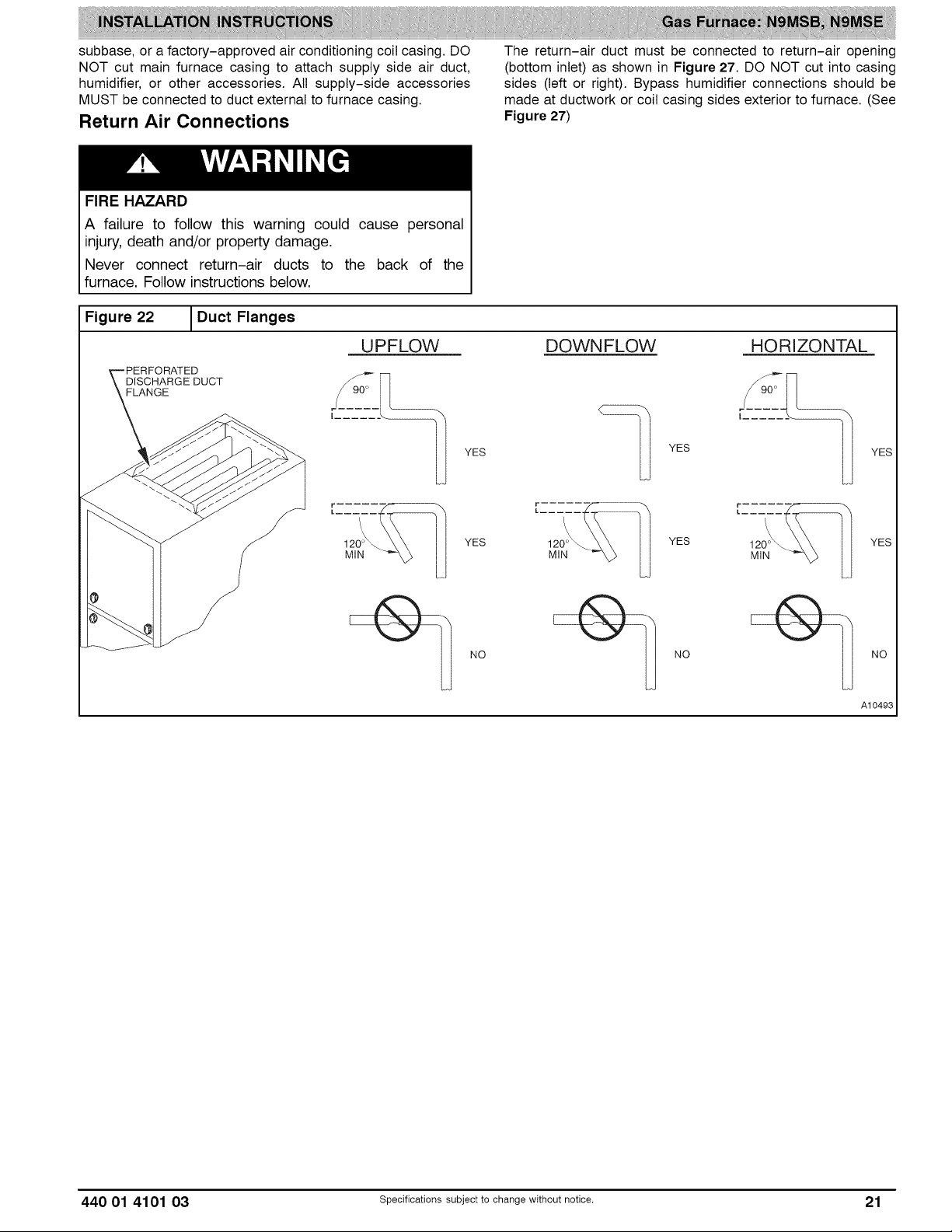
subbase, or a factory-approved air conditioning coil casing. DO
NOT cut main furnace casing to attach supply side air duct,
humidifier, or other accessories. All supply-side accessories
MUST be connected to duct external to furnace casing.
Return Air Connections
FIRE HAZARD
A failure to follow this warning could cause personal
injury, death and/or property damage.
Never connect return-air ducts to the back of the
furnace. Follow instructions below.
Figure 22 _Duct Flanges
UPFLOW DOWNFLOW HORIZONTAL
_RATED
FLANGE
I ......
The return-air duct must be connected to return-air opening
(bottom inlet) as shown in Figure 27. DO NOT cut into casing
sides (left or right). Bypass humidifier connections should be
made at ductwork or coil casing sides exterior to furnace. (See
Figure 27)
I ......
120°_
MIN
YES
\
YES YES
NO NO NO
YES
YES
A10493
440 01 4101 03 Specificationssubjecttochange without notice. 21
Page 22
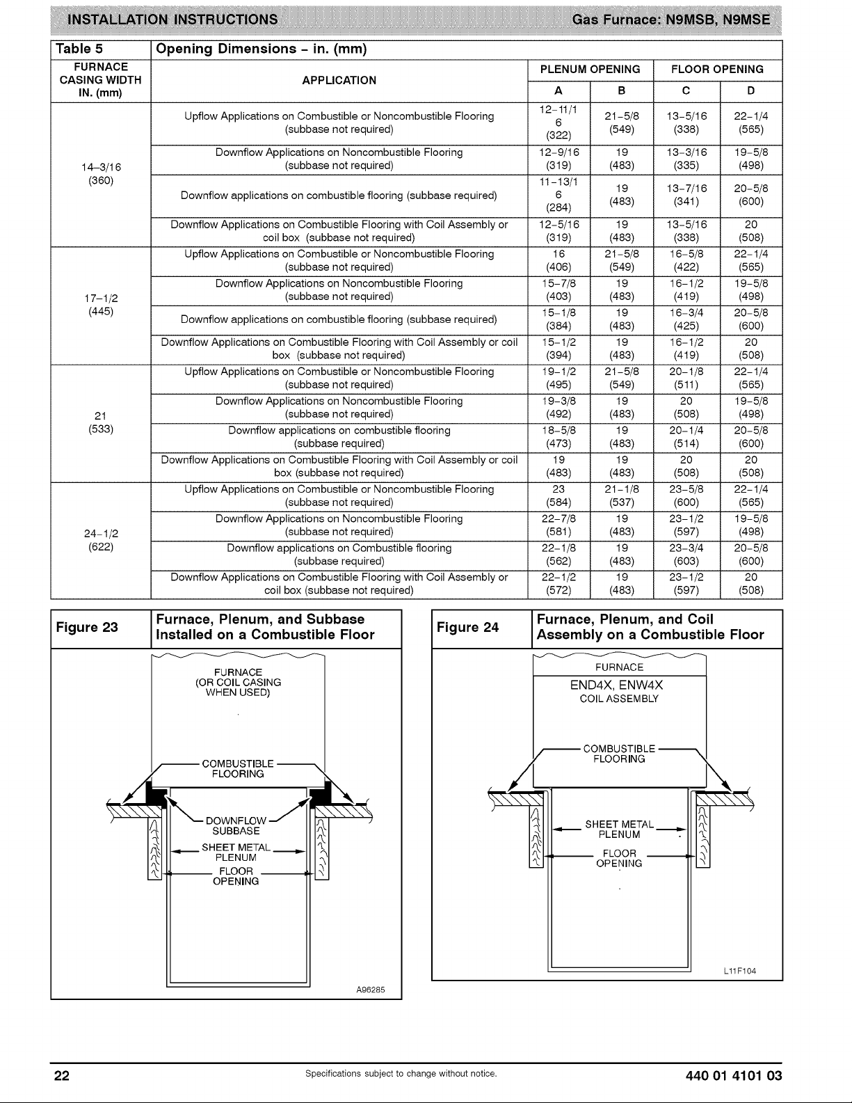
iTable 5
FURNACE
CASI NG WIDTH
IN, (mm)
14-3/16 (subbase not required) (319) (483) (335) (498)
(360) 11-13/1 19 13-7/16 20-5/8
17-1/2 (subbase not required) (403) (483) (419) (498)
(445) 15-1/8 19 16-3/4 20-5/8
21 (subbase not required) (492) (483) (508) (498)
(533) Downflow applications on combustible flooring 18-5/8 19 20-1/4 20-5/8
24-1/2 (subbase not required) (581) (483) (597) (498)
(622) Downflow applications on Combustible flooring 22-1/8 19 23-3/4 20-5/8
Opening Dimensions - in. (mm)
APPLICATION
PLENUM OPENING
12-11/1
Upflow Applications on Combustible or Noncombustible Flooring 6 21-5/8 13-5/16 22-1/4
(subbase not required) (322) (549) (338) (565)
Downflow Applications on Noncombustible Flooring 12-9/16 19 13-3/16 19-5/8
Downflow applications on combustible flooring (subbase required) 6
(284) (483) (34t) (600)
Downflow Applications on Combustible Flooring with Coil Assembly or 12-5/16 19 13-5/16 20
coil box (subbase not required) (319) (483) (338) (508)
Upflow Applications on Combustible or Noncombustible Flooring 16 21-5/8 16-5/8 22-1/4
(subbase not required) (406) (549) (422) (565)
Downflow Applications on Noncombustible Flooring 15-7/8 19 16-1/2 19-5/8
Downflow applications on combustible flooring (subbase required) (384) (483) (425) (600)
Downflow Applications on Combustible Flooring with Coil Assembly or coil 15-1/2 19 16-1/2 20
box (subbase not required) (394) (483) (419) (508)
Upflow Applications on Combustible or Noncombustible Flooring 19-1/2 21-5/8 20-1/8 22-1/4
(subbase not required) (495) (549) (511) (565)
Downflow Applications on Noncombustible Flooring 19-3/8 19 20 19-5/8
(subbase required) (473) (483) (514) (600)
Downflow Applications on Combustible Flooring with Coil Assembly or coil 19 19 20 20
box (subbase not required) (483) (483) (508) (508)
Upflow Applications on Combustible or Noncombustible Flooring 23 21-1/8 23-5/8 22-1/4
(subbase not required) (584) (537) (600) (565)
Downflow Applications on Noncombustible Flooring 22-7/8 19 23-1/2 19-5/8
(subbase required) (562) (483) (603) (600)
Downflow Applications on Combustible Flooring with Coil Assembly or 22-1/2 19 23-1/2 20
(572) (483) (597) (508)coil box (subbase not required)
FLOOR OPENING
C DA B
Figure 23
Furnace, Plenum, and Subbase
Installed on a Combustible Floor
FURNACE
(OR COIL CASING
WHEN USED)
COMBUSTIBLE
FLOORING
SUBBASE
SHEET METAL
PLENUM
-- FLOOR --
OPENING
A96285
Figure 24
Furnace, Plenum, and Coil
Assembly on a Combustible Floor
FURNACE
END4X, ENW4X
COIL ASSEMBLY
_ COMBUSTIBLE --
FLOORING
SHEET METAL
PLENUM
FLOOR
OPENING
\
-!
E
Lll F104
22 Specificationssubjectto change without notice. 440 01 4101 03
Page 23

Bottom Return Air Inlet
These furnaces are shipped with bottom closure panel installed
in bottom return-air opening. Remove and discard this panel
when bottom return air is used. To remove bottom closure
panel, perform the following:
1. Tilt or raise furnace and remove four (4) screws holding
bottom plate. (See Figure 19)
2. Remove bottom plate.
3. Remove bottom closure panel.
4. Reinstall bottom plate and screws.
HORIZONTAL INSTALLATION
NOTE: The furnace must be pitched forward as shown in
Figure 18 for proper condensate drainage.
FIRE, EXPLOSION, AND CARBON MONOXIDE
POISONING HAZARD
Failure to follow this warning could result in personal
injury, death, or property damage.
Do not install the furnace on its back or hang furnace with
control compartment facing downward. Safety control
operation will be adversely affected. Never connect
return-air ducts to the back of the furnace.
MINOR PROPERTY HAZARD
Failure to follow this caution may result in minor property
damage.
Local codes may require a drain pan under entire furnace
and condensate trap when a condensing furnace is used
in an attic application or over a finished ceiling.
The furnace can be installed horizontally in an attic or
crawlspace on either the left-hand (LH) or right-hand (RH)
side. The furnace can be hung from floor joists, rafters or
trusses or installed on a non-combustible platform, blocks,
bricks or pad.
Suspended Furnace Support
The furnace may be supported under the entire length of the
furnace with threaded rod and angle iron. (See Figure 25)
Secure angle iron to bottom of furnace as shown.
Platform Furnace Support
Construct working platform at location where all required
furnace clearances are met. (See Table 1 and Figure 26) For
furnaces with 1-in. (25 mm) clearance requirement on side, set
furnace on non-combustible blocks, bricks or angle iron. For
crawlspace installations, if the furnace is not suspended from
the floor joists, the ground underneath furnace must be level
and the furnace set on blocks or bricks.
Figure 25
Suspended Furnace Installation
NOTE: EXTEND ANGLE
IRON OUT FOR
COIL SUPPORT
ROD LOCATION
USING DIMPLE I
LOCATORS
HEX NUT
& WASHER (4)
REQD. PER ROD
COMBUSTION. AIR PiPE
(SEE VENTING SECTION)
VENT
IN ROD
NOTES: 1. A 1 In. (25mm) clearance minimum between
top of furnace and combustible material
2. The entire length of furnace must be
supported when furnace is used in horizontal
position to ensure proper drainage.
3. Furnace shown is a direct vent application,
Refer to the Venting section for agowable vent
configurations.
Al1155
NOTE: Local codes may require a drain pan and condensate trap when a condensing furnace is installed over a finished
ceiling.
440 01 4101 03 Specifications subject to change without notice. 23
Page 24

Figure 26 I Working Platform for Attic Installation
COMBUSTION - AIR PIPE VENT
(SEE VENTING SECTION)
(305 mm) MIN HORIZONTAL PIPE
SECTION IS RECOMMENDED WITH A
SHORT (5 TO 8 FT / 1.5 TO 2.4 M) VENT
SYSTEM TO REDUCE EXCESSIVE
CONDENSATE DROPLETS FROM
EXITING THE VENT PIPE.
INDOOR
COIL
30" (762 mm)
Min Work Area
ROLLOUT PROTECTION RE-
QUIRED Install 1.2" x 22" (305 x 559
mm) sheet metal in front of burner
compartment area.
CONDENSATE
TRAP
NOTE: FURNACE SHOWN AS DIRECT VENT APPLICATION. REFER TO THE
VENTING SECTION FOR ALLOWABLE VENT CONFIGURATIONS
NOTE:
Local codes may require a drain pan and condensate trap when a condensing furnace is installed over a finished
ceiling.
Roll-Out Protection
Provide a minimum 12-in. x 22-in. (305 x 559 mm) piece of
sheet metal for flame roll-out protection in front of burner area
for furnaces closer than 12-in. (305 mm) above the
combustible deck or suspended furnaces closer than 12-in.
(305mm) to joists. The sheet metal MUST extend underneath
the furnace casing by 1-in. (25mm) with the door removed.
The bottom closure panel may be used for flame roll-out
protection when bottom of furnace is used for return air
connection. See Figure 26 for proper orientation of roll-out
shield.
Supply Air Connections
For a furnace not equipped with a cooling coil, the outlet duct
shall be provided with a removable access panel. This opening
shall be accessible when the furnace is installed and shall be of
such a size that the heat exchanger can be viewed for possible
openings using light assistance or a probe can be inserted for
sampling the air stream. The cover attachment shall prevent
leaks.
Connect supply-air duct to flanges on furnace supply-air
outlet. Bend flange upward to 90° with wide duct pliers. (See
Figure 22) The supply-air duct must be connected to ONLY
the furnace supply-outlet-air duct flanges or air conditioning
coil casing (when used). DO NOT cut main furnace casing side
to attach supply air duct, humidifier, or other accessories. All
supply-side accessories MUST be connected to duct external
to furnace main casing.
Return Air Connections
The return-air duct may be connected to bottom of the furnace.
The side of casing that faces downward may also be used for
return air connection. A combination of the bottom and
downward facing side may also be used. The upward facing
A1ff54
side of the casing cannot be used as a return air connection.
Bypass humidifier may be attached into unused return air side
of the furnace casing. (See Figure 29)
Bottom Return Air Inlet
These furnaces are shipped with bottom closure panel installed
in bottom return-air opening. Remove and discard this panel
when bottom return air is used. To remove bottom closure
panel, perform the following:
1. Tilt or raise furnace and remove four (4) screws holding
bottom plate. (See Figure 19)
2. Remove bottom plate.
3. Remove bottom closure panel.
4. Reinstall bottom plate and screws.
Side Return Air Inlet
These furnaces are shipped with bottom closure panel installed
in bottom return-air opening. This panel MUST be in place
when side return air inlet(s) are used without a bottom return air
inlet.
Not all horizontal furnaces are approved for side return air
connections (See Figure 29)
Filter Arrangement
FIRE, CARBON MONOXIDE AND POISONING
HAZARD
Failure to follow this warning could result in personal
injury, or death.
Never operate a furnace without afilter or filtration device
installed. Never operate a furnace with filter or filtration
device access doors removed.
24 specificationssubjectto change without notice. 440 01 4101 03
Page 25

Furnaces shipped without a filter rack:
There are no provisions for an internal filter in these furnaces.
An external filter rack is required and is purchased separately.
A field supplied accessory air cleaner may also be used in
place of the filter rack.
For upflow applications, the filter can be installed on either side
of the furnace, the bottom of the furnace or any combination of
side and bottom of the furnace. (See Figure 28, Figure 31, and
Figure 30)
For downfiow applications, the filter rack (or field supplied
accessory air cleaner) must only be connected to the bottom
opening on the furnace (See Figure 27 and Figure 30 and
Table 9).
For horizontal applications, the filter rack (or field supplied
accessory air cleaner) can be connected to the bottom opening
on the furnace. For side return use in the horizontal position,
refer to Figure 29. If both side and bottom openings are used in
Figure 29, each opening used will require a filter.
A filter rack or any field supplied accessory air cleaner can also
be installed in the common return duct prior to entering the
return air opening in any orientation.
See Table 6 for recommended filter size details.
Table 6 Filter Size Information - in. (mm)
FURNACE
CASING
WIDTH
14-3/16 16 x 25 x 3/4 14 x 25 x 3/4 Washable*
(360) (406 x 635 x 19) (356 x 635 x 19)
17-1/2 16 x 25 x 3/4 16 x 25 x 3/4 Washable*
(445) (406 x 635 x 19) (406 x 635 x 19)
21 (533) (406 x 635 x 19) (508 x 635 x 19)
24-1/2 16 x 25 x 3/4 24 x 25 x 3/4 Washable*
(622) (406 x 635 x 19) (610 x 635 x 19)
Recommended to maintain air filter face velocity. See Product Data for part
number.
SIDE RETURN
16 x 25 x 3/4 20 x 25 x 3/4 Washable*
Refer to the instructions supplied with the Filter Rack or
accessory air filter for additional assembly and installation
options.
FILTERSIZE
BOTTOM
RETURN
FILTER
TYPE
Filter and Return Duct Sizing
Pressure drop must be taken into account when sizing filters,
filter racks, IAQ devices, and associated system ductwork. See
Table7 for a comparison of Pressure Drop (initial/clean
resistance to airflow) versus Airflow for a variety of filter media
types and sizes. These are representative numbers. Consult
the filter or IAQ device manufacturers' specification sheet for
performance data for a particular filter media or IAQ device.
Design the filter and associated ductwork for the best match of
pressure drop versus filter size. Best practice usually chooses
filter systems with pressure drops under 0.2 in wc (50 Pa), with
the best blower electrical efficiency and system airflow
performance occurring with filter pressure drops under 0.1 in
wg (25 Pa).
Due to the relatively high pressure drops of 1-in (25 mm) thick
after-market filter media, it is recommended that the filtration
system be designed for at least 2-in (51 mm) thick media.
TIPS FROM CONTRACTORS: Install a media cabinet capable
of incorporating a 4-in (102 mm) thick media filter. This allows
room for future upgrades to other IAQ devices.
Design the duct system FIRST to determine how much
pressure drop may be allowed in the filter system. See
the AIR DUCTS section. Excessive filter pressure drop
often compromises system airflow and duct perform-
ance, causes inadequate airflow to the furthest ends of
the duct system, as well as causes excess noise and
higher than anticipated electrical consumption.
Provide duct transitions, as required, to smoothly transition
airflow from the return duct system to the filter (or IAQ device)
to the furnace when the dimensions of the ductwork or furnace
return air opening do not match the required filter or IAQ device
dimensions. See the instructions supplied with
factory-accessory duct adapters.
440 01 4101 03 Specificationssubjectto change without notice. 25
Page 26
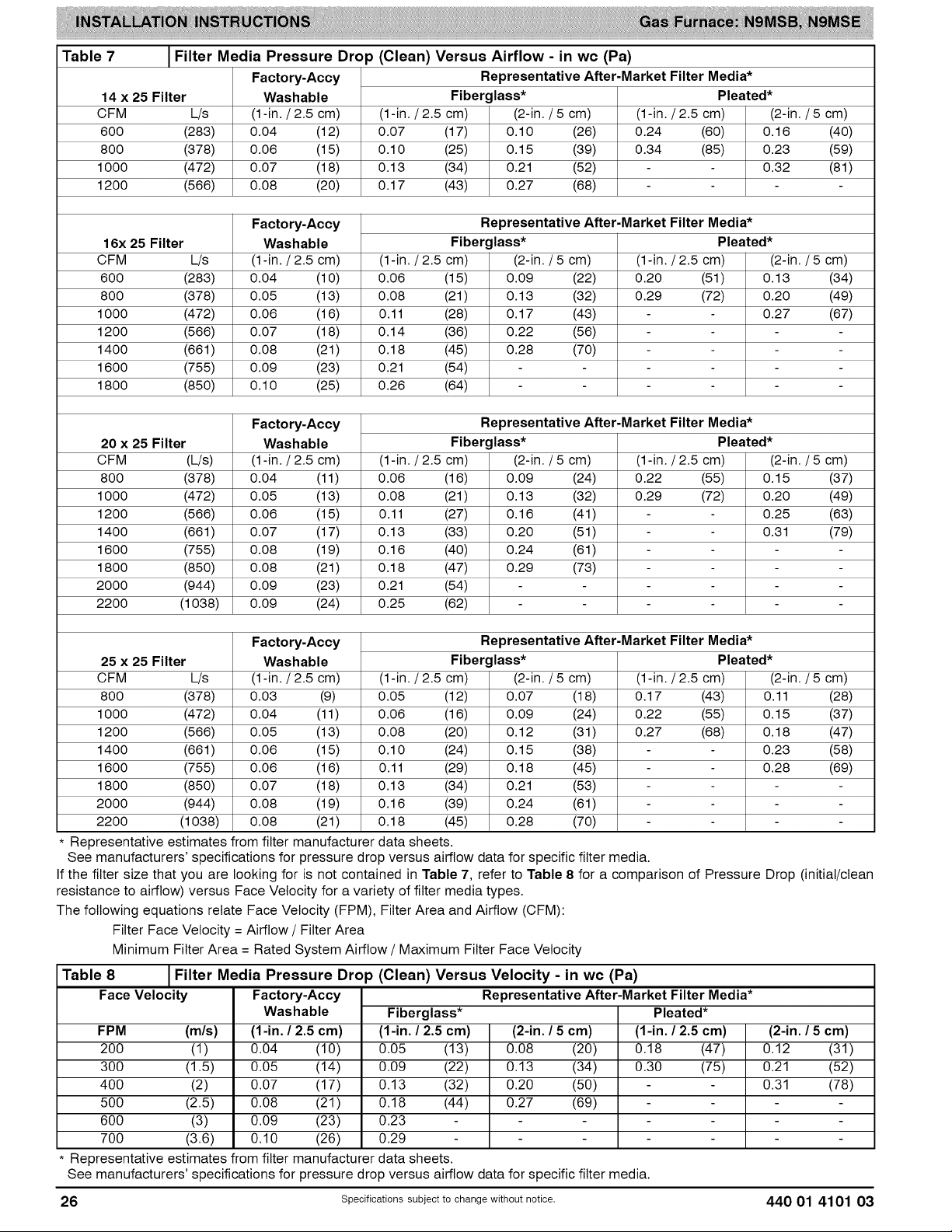
Table 7 Filter Media Pressure Drop (Clean) Versus Airflow - in wc (Pa)
Representative After-Market Filter Media*
Fiberglass*
14 x 25 Filter
OFM L/s
600 (283)
800 (378)
1000 (472)
1200 (566)
Factory-Accy
Washable
(1-in./2.5 cm)
0.04 (12)
0.06 (15)
0.07 (18)
0.08 (20)
(1-in./2.5 cm) (2-in./5 cm)
0.07 (17) 0.10 (26)
O.10 (25) O.15 (39)
0.13 (34) 0.21 (52)
O.17 (43) 0.27 (68)
Pleated*
(1-in./2.5 cm) (2-in.
0.24 (60) O.16
0.34 (85) 0.23
0.32
/ 5 cm)
(40)
(59)
(81)
Representative After-Market Filter Media*
Fiberglass* Pleated*
(2-in.
0.13
0.20
0.27
Representative After-Market Filter Media*
Fiberglass* Pleated*
(2-in.
0.15
0.20
0.25
0.31
Representative After-Market Filter Media*
Fiberglass* Pleated*
(2-in.
0.11
0.15
0.18
0.23
0.28
16x 25 Filter
CFM L/s
600 (283)
800 (378)
1000 (472)
1200 (566)
1400 (661)
1600 (755)
1800 (850)
20 x 25 Filter
CFM (L/s)
800 (378)
1000 (472)
1200 (566)
1400 (661)
1600 (755)
1800 (850)
2000 (944)
2200 (1038)
25 x 25 Filter
CFM L/s
800 (378)
1000 (472)
1200 (566)
1400 (661)
1600 (755)
1800 (850)
2000 (944)
2200 (1038)
Factory-Accy
Washable
(1-in./2.5 cm)
0.04 (1 O)
0.05 (13)
0.06 (16)
0.07 (18)
0.08 (21)
0.09 (23)
O.10 (25)
(1-in. /2.5 cm) (2-in. /5 cm) (1-in. /2.5 cm) /5 cm)
0.06 (15) 0.09 (22) 0.20 (51) (34)
0.08 (21) O.13 (32) 0.29 (72) (49)
0.11 (28) 0.17 (43) (67)
O.14 (36) 0.22 (56)
O.18 (45) 0.28 (70)
0.21 (54)
0.26 (64)
Factory-Accy
Washable
(1-in./2.5 cm) (1-in./2.5 cm) (2-in./5 cm) (1-in./2.5 cm) /5 cm)
0.04 (11) 0.06 (16) 0.09 (24) 0.22 (55) (37)
0.05 (13) 0.08 (21) 0.13 (32) 0.29 (72) (49)
0.06 (15) 0.11 (27) 0.16 (41) (63)
0.07 (17) 0.13 (33) 0.20 (51) (79)
0.08 (19) O.16 (40) 0.24 (61)
0.08 (21) O.18 (47) 0.29 (73)
0.09 (23) 0.21 (54)
0.09 (24) 0.25 (62)
Factory-Accy
Washable
(1-in./2.5 cm) (1-in./2.5 cm) (2-in./5 cm) (1-in./2.5 cm) /5 cm)
0.03 (9) 0.05 (12) 0.07 (18) O.17 (43) (28)
0.04 (11) 0.06 (16) 0.09 (24) 0.22 (55) (37)
0.05 (13) 0.08 (20) 0.12 (31) 0.27 (68) (47)
0.06 (15) 0.10 (24) 0.15 (38) (58)
0.06 (16) O.11 (29) O.18 (45) (69)
0.07 (18) O.13 (34) 0.21 (53)
0.08 (19) 0.16 (39) 0.24 (61)
0.08 (21) O.18 (45) 0.28 (70)
* Representative estimates from filter manufacturer data sheets.
See manufacturers' specifications for pressure drop versus airflow data for specific filter media.
If the filter size that you are looking for is not contained in Table 7, refer to Table 8 for a comparison of Pressure Drop (initial/clean
resistance to airflow) versus Face Velocity for a variety of filter media types.
The following equations relate Face Velocity (FPM), Filter Area and Airflow (CFM):
Filter Face Velocity = Airflow / Filter Area
Minimum Filter Area = Rated System Airflow / Maximum Filter Face Velocity
Table 8
Face
FPM (m/s)
200 (I)
300 (1.5)
400 (2)
500 (2.5)
600 (3)
700 (3.6)
Filter Media Pressure Drop (Clean) Versus Velocity - in wc (Pa)
Velocity Factory-Accy Representative After-Market Filter Media*
Washable
(1-in. / 2.5 cm)
0.04 (10)
0.05 (14)
0.07 (17)
0.08 (21)
0.09 (23)
0.10 (26)
Fiberglass*
(1-in. / 2.5 cm)
0.05 (13)
0.09 (22)
0.13 (32)
0.18 (44)
0.23
0.29
(2-in. / 5 cm)
0.08 (20)
0.13 (34)
0.20 (50)
0.27 (69)
Pleated*
(1-in. / 2.5 cm)
0.18 (47)
0.30 (75)
(2-in. / 5 cm)
0.12 (31)
0.21 (52)
0.31 (78)
* Representative estimates from filter manufacturer data sheets.
See manufacturers' specifications for pressure drop versus airflow data for specific filter media.
26 specificationssubjectto change without notice. 440 01 4101 03
Page 27

Figure 27
SIDE RETURN
NOT PERMITTED
FOR ANY MODEL
JDownflow Return AirConfigurations and Restrictions
/ (17 RETURN
......................._/z/i ......................... SIDE RETURN
AIR
O
®
®
i s_LY L,0F033
Upflow Return Air Configurations
Figure 28 and Restrictions
SUPPLY t
............._iR J/_....................
NOT PERMI]qED
FOR ANY MODEL
External
Figure 30
Filter Cabinet Configurations
Accessory Bottom Filter Rack
m
om
0
® @
@ @
L10F031
B
A
m
o
® ®
® ®
®
)
RETURN
AIR
SUPPLY
AIR
RETURN
AIR
AIR C!_ RETURN AIR
RETURN I UPFLOW
Figure 29 Configurations and Restrictions
HORIZONTAL TOP
RETURN NOT
PERMITTED FOR
ANY MODEL
IHorizontal Return Air
RESTRICTIONS L10F032
24
RETURN
AIR
* NOTE: RESTRICTION SAME FOR HORIZONAL
HORIZONAL LEFT RETURN AIR
SIDE RETURN AIR NOT PERMITTED FOR 2000 CFM AND ABOVE OF AIR
FLOW L10F034
RETURN
AIR
0
RESTRICTIONS
e
,3
A
22-5/t 6
(566.4)
I
28-7/16
(722.2)
o
,3
o
o
o
o
e
e
e
e
2-3/t 6 - .=,_=,
(55.5)
Table 9 Dimensional Drawing - in. (mm)
KIT NO. A B
NAH B00501FF 14-3/16 11-3/8 14-1/4
NAHB00601 FF 17-1/2 14-5/8 17-5/8
NAHB00701FF
NAH B00801FF 24-1/2 21-5/8 24-5/8
FURNACE
WIDTH
(360.4) (289) (362)
(444.5) (371.5) (447.7)
21 18-1/8 21-1/8
(533.4) (460.4) (536.6)
(622.3) (549.3) (625.5)
o
440 01 4101 03 specificationssubjectto change without notice. 27
Page 28

Figure 31 JAccessory Side Filter Rack
L10F027
Systems Design Guidelines reference tables available from
your local distributor. The duct system should be sized to
handle the required system design CFM at the design external
static pressure. The furnace airflow rates are provided in the
Service and Technical Support Manual. When a furnace is
installed so that the supply ducts carry air circulated by the
furnace to areas outside the space containing the furnace, the
return air shall also be handled by duct(s) sealed to the furnace
casing and terminating outside the space containing the
furnace.
Secure ductwork with proper fasteners for type of ductwork
used. Seal supply- and return-duct connections to furnace
with code approved tape or duct sealer.
NOTE: Flexible connections should be used between ductwork
and furnace to prevent transmission of vibration.
Ductwork passing through unconditioned space should be
insulated to enhance system performance. When air
conditioning is used, a vapor barrier is recommended.
Maintain a 1-in. (25 mm) clearance from combustible materials
to supply air ductwork for a distance of 36-in. (914 mm)
horizontally from the furnace. See NFPA 90B or local code for
further requirements.
Return Duct Sizing
Refer to the Filter Selection and Duct Sizing section for
information on the proper selection of filter sizes and the
associated ductwork and duct transitions. Improperly designed
filtering systems and return ductwork are the most common
causes of airflow and/or noise complaints in HVAC systems.
Ductwork Acoustical Treatment
NOTE: Metal duct systems that do not have a 90 degree elbow
and 10 ft. (3 M) of main duct to the first branch take-off may
require internal acoustical lining. As an alternative, fibrous
ductwork may be used if constructed and installed in
accordance with the latest edition of SMACNA construction
standard on fibrous glass ducts. Both acoustical lining and
fibrous ductwork shall comply with NFPA 90B as tested by UL
Standard 181 for Class 1 Rigid air ducts.
NOTE: For horizontal applications, the top most flange may be
bent past 90 _' to allow the evaporator coil to hang on the
flange temporarily while the remaining attachment and sealing
of the coil are performed.
GAS PIPING
L12F023
Air Ducts
FIRE OR EXPLOSION HAZARD
Failure to follow this warning could result in personal
injury, death, and/or property damage.
Never purge a gas line into a combustion chamber.
Many states, provinces and localities are considering
or have implemented standards and/or restrictions on
duct sizing practices, ductwork leakage, and/or duct-
work thermal, airflow and electrical efficiencies. CON-
SULT LOCAL CODE OFFICIALS for ductwork design
Never test for gas leaks with an open flame. Use a
commercially available soap solution made specifically
for the detection of leaks to check all connections. A
fire or explosion may result causing property damage,
3ersonal injury or loss of life.
and performance requirements in your area.
General Requirements
The duct system should be designed and sized according to
accepted national standards such as those published by: Air
Conditioning Contractors Association (ACCA Manual D), Sheet
Metal and Air Conditioning Contractors National Association
(SMACNA) or American Society of Heating, Refrigerating and
Air Conditioning Engineers (ASHRAE) or consult The Air
28 Specificationssubjectto change without notice. 440 01 4101 03
FIRE OR EXPLOSION HAZARD
Failure to follow this warning could result in personal
injury, death, and/or property damage.
Use proper length of pipe to avoid stress on gas con-
trol manifold and a gas leak.
Page 29
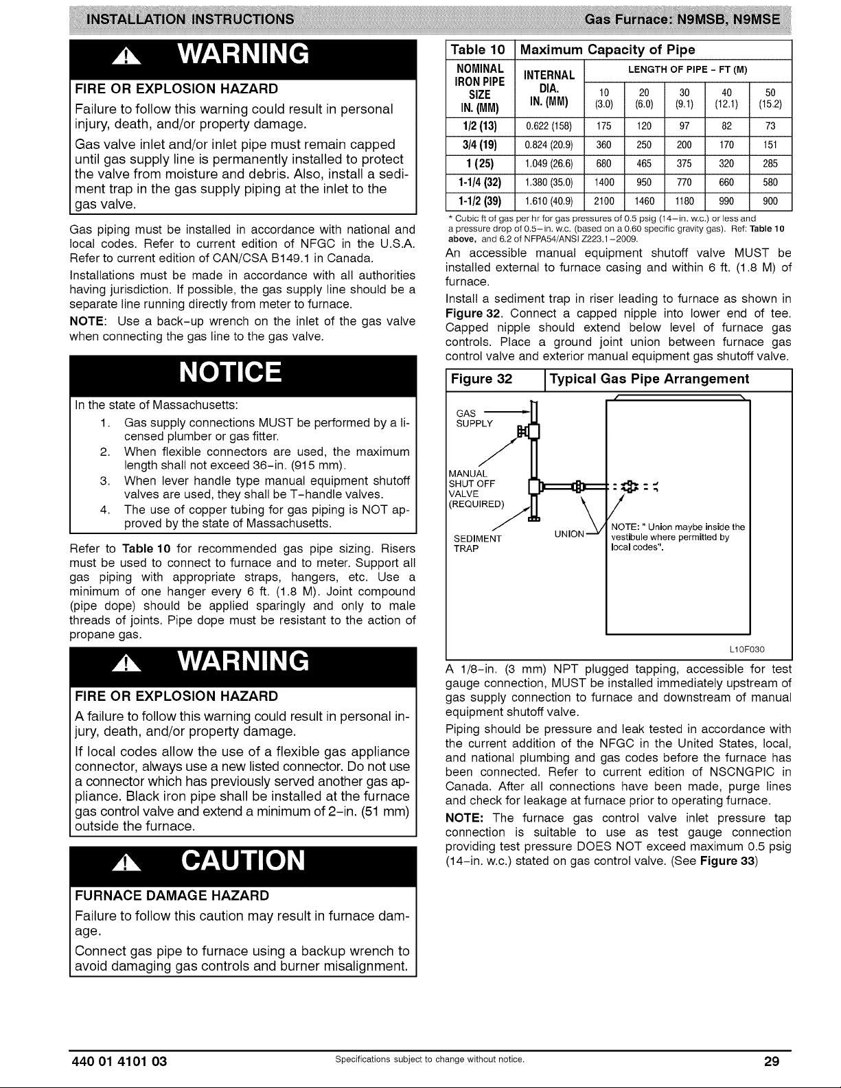
FIRE OR EXPLOSION HAZARD
Failure to follow this warning could result in personal
injury, death, and/or property damage.
Gas valve inlet and/or inlet pipe must remain capped
until gas supply line is permanently installed to protect
the valve from moisture and debris. Also, install a sedi-
ment trap in the gas supply piping at the inlet to the
gas valve.
Gas piping must be installed in accordance with national and
local codes. Refer to current edition of NFGC in the U.S.A.
Refer to current edition of CAN/CSA B149.1 in Canada.
Installations must be made in accordance with all authorities
having jurisdiction. If possible, the gas supply line should be a
separate line running directly from meter to furnace.
NOTE: Use a back-up wrench on the inlet of the gas valve
when connecting the gas line to the gas valve.
In the state of Massachusetts:
1. Gas supply connections MUST be performed by a li-
censed plumber or gas fitter.
2. When flexible connectors are used, the maximum
length shall not exceed 36-in. (915 mm).
3. When lever handle type manual equipment shutoff
valves are used, they shall be T-handle valves.
4. The use of copper tubing for gas piping is NOT ap-
proved by the state of Massachusetts.
Refer to Table 10 for recommended gas pipe sizing. Risers
must be used to connect to furnace and to meter. Support all
gas piping with appropriate straps, hangers, etc. Use a
minimum of one hanger every 6 ft. (1.8 M). Joint compound
(pipe dope) should be applied sparingly and only to male
threads of joints. Pipe dope must be resistant to the action of
propane gas.
FIRE OR EXPLOSION HAZARD
A failure to follow this warning could result in personal in-
jury, death, and/or property damage.
If local codes allow the use of a flexible gas appliance
connector, always use a new listed connector. Do not use
a connector which has previously served another gas ap-
31iance. Black iron pipe shall be installed at the furnace
gas control valve and extend a minimum of 2-in. (51 mm)
outside the furnace.
Table 10 Maximum Capacity of Pipe
NOMINAL INTERNAL LENGTH OF PIPE - FT (a)
IRONPIPE
SIZE DIA, 10 2O 30 40 50
IN.(MM) IN.(MM) (3.0) (6.0) (9.1) (12.1) (15.2)
1/2(13) 0,622(158) 175 120 97 82 73
3/4 (19) 0,824(20,9) 360 250 200 170 151
1(25) 1.049(26,6) 680 465 375 320 285
1-1/4(32) 1.380(35.0) 1400 950 770 660 580
1-1/2(39) 1.610(40.9) 2100 1460 1180 990 900
* Cubic ft of gas per hr for gas pressures of 0.5 psig (14-in. w.c.) or less and
a pressure drop of 0.5-in. w.c. (based on a 0.60 specific gravity gas). Ref: Table 10
above, and 6.2 of NFPA54/ANSI Z223.1-2009.
An accessible manual equipment shutoff valve MUST be
installed external to furnace casing and within 6 ft. (1.8 M) of
furnace.
Install a sediment trap in riser leading to furnace as shown in
Figure 32. Connect a capped nipple into lower end of tee.
Capped nipple should extend below level of furnace gas
controls. Place a ground joint union between furnace gas
control valve and exterior manual equipment gas shutoff valve.
Figure 32 ITypical Gas Pipe Arrangement
MANUAL U
SHUvTEOFF
/
\
SEDIMEN_TT UNION "-'v
TRAP
A 1/8-in. (3 mm) NPT plugged tapping, accessible for test
gauge connection, MUST be installed immediately upstream of
gas supply connection to furnace and downstream of manual
equipment shutoff valve.
Piping should be pressure and leak tested in accordance with
the current addition of the NFGC in the United States, local,
and national plumbing and gas codes before the furnace has
been connected. Refer to current edition of NSCNGPIC in
Canada. After all connections have been made, purge lines
and check for leakage at furnace prior to operating furnace.
NOTE: The furnace gas control valve inlet pressure tap
connection is suitable to use as test gauge connection
providing test pressure DOES NOT exceed maximum 0.5 psig
(14-in. w.c.) stated on gas control valve. (See Figure 33)
NOTE: " Union maybe inside the
vestibule where permitted by
local codes".
LIOF030
FURNACE DAMAGE HAZARD
Failure to follow this caution may result in furnace dam-
age.
Connect gas pipe to furnace using a backup wrench to
avoid damaging gas controls and burner misalignment.
440 01 4101 03 Specificationssubjectto change without notice. 29
Page 30
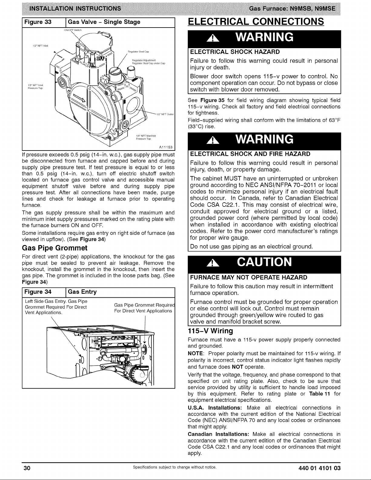
Figure 33
I Gas Valve - Single Stage
ON/OFF Switch
\
ELECTRICAL CONNECTIONS
Regulator Seal Cap
Regulatol Adjustment
Regulator Sea_ Cap l_nder Cap
1/8" NPT In_et
Pressure Tap
1,8' NPT Manifold
Pressure Tap
Al1153
If pressure exceeds 0.5 psig (14-in. w.c.), gas supply pipe must
be disconnected from furnace and capped before and during
supply pipe pressure test. If test pressure is equal to or less
than 0.5 psig (14-in. w.c.), turn off electric shutoff switch
located on furnace gas control valve and accessible manual
equipment shutoff valve before and during supply pipe
pressure test. After all connections have been made, purge
lines and check for leakage at furnace prior to operating
furnace.
The gas supply pressure shall be within the maximum and
minimum inlet supply pressures marked on the rating plate with
the furnace burners ON and OFF.
Some installations require gas entry on right side of furnace (as
viewed in upflow). (See Figure 34)
Gas Pipe Grommet
For direct vent (2-pipe) applications, the knockout for the gas
pipe must be sealed to prevent air leakage. Remove the
knockout, install the grommet in the knockout, then insert the
gas pipe. The grommet is included in the loose parts bag. (See
Figure 34)
Figure 34 I Gas Entry
LeftSideGas Entry.Gas Pipe
GrommetRequiredFor Direct Gas PipeGrommet Required
VentApplications. For DirectVentApplications
ELECTRICAL SHOCK HAZARD
Failure to follow this warning could result in personal
injury or death.
Blower door switch opens 115-v power to control. No
component operation can occur. Do not bypass or close
switch with blower door removed.
See Figure 35 for field wiring diagram showing typical field
115-v wiring. Check all factory and field electrical connections
for tightness.
Field-supplied wiring shall conform with the limitations of 63°F
(33°C) rise.
ELECTRICAL SHOCK AND FIRE HAZARD
Failure to follow this warning could result in personal
injury, death, or property damage.
The cabinet MUST have an uninterrupted or unbroken
ground according to NEC ANSI/NFPA 70-2011 or local
codes to minimize personal injury if an electrical fault
should occur. In Canada, refer to Canadian Electrical
Code CSA C22.1. This may consist of electrical wire,
conduit approved for electrical ground or a listed,
grounded power cord (where permitted by local code)
when installed in accordance with existing electrical
codes. Refer to the power cord manufacturer's ratings
for proper wire gauge.
Do not use gas piping as an electrical ground.
FURNACE MAY NOT OPERATE HAZARD
Failure to follow this caution may result in intermittent
furnace operation.
Furnace control must be grounded for proper operation
or else control will lock out. Control must remain
grounded through green/yellow wire routed to gas
valve and manifold bracket screw.
115-V Wiring
Furnace must have a 115-v power supply properly connected
and grounded.
NOTE: Proper polarity must be maintained for 115-v wiring. If
polarity is incorrect, control status indicator light flashes rapidly
and furnace does NOT operate.
Verify that the voltage, frequency, and phase correspond to that
specified on unit rating plate. Also, check to be sure that
service provided by utility is sufficient to handle load imposed
by this equipment. Refer to rating plate or Table11 for
equipment electrical specifications.
U,S,A, Installations: Make all electrical connections in
accordance with the current edition of the National Electrical
Code (NEC) ANSI/NFPA 70 and any local codes or ordinances
that might apply.
Canadian Installations: Make all electrical connections in
accordance with the current edition of the Canadian Electrical
Code CSA C22.1 and any local codes or ordinances that might
apply.
30 Specificationssubjectto change without notice. 440 01 4101 03
Page 31

FIRE HAZARD
Failure to follow this warning could result in personal SWITCH
injury, death, or property damage.
Do not connect aluminum wire between disconnect
switch and furnace. Use only copper wire.
Use a separate, fused branch electrical circuit with a properly
sized fuse or circuit breaker for this furnace. See Table 11 for
wire size and fuse specifications. A readily accessible means of
electrical disconnect must be located within sight of the
furnace.
Figure 35
[Heating and Cooling Application Single Stage Wiring Diagram
.... FIELD 24 VWIRING
.... FIELD 115,208/230-, 460 VWIRING
-- FACTORY24 VWIRING
®
FACTORY115V WIRING
Al1146
J-Box Installation
FIRE OR ELECTRICAL SHOCK HAZARD
Failure to follow this warning could result in personal
injury, death, or property damage.
If field-supplied manual disconnect switch is to be
mounted on furnace casing side, select a location where
a drill or fastener cannot damage electrical or gas
components.
The J-Box is used when field line voltage electrical connections
are made to the furnace wiring harness inside the furnace
casing. The J-Box is not required if a field-supplied electrical
box is attached to the outside of the furnace casing and the box
is grounded to the green ground wire of the main wiring
harness and the earth ground of the field electrical supply.
The J-Box cover, mounting bracket and screws are shipped in
the loose parts bag included with the furnace. The J-Box can
be mounted on the left or right side of the casing, as viewed
from the upflow position. (See Figure 36)
Figure 36 Optional J-Box Locations
Representative drawing only, some models may vary in appearance
OPTIONAL
J-BOX
LOCATIONS
7
J
Al1387
L12F024
440 01 4101 03 Specificationssubjectto change without notice. 31
Page 32

Figure 37
J-BOX
MOUNTING
SCREWS
J-BOX --\
MOUNTING "--..
BRACKET
J-Box Bracket Installation
f
Figure 38
\
\
I Field-Supplied Electrical Box onFurnace Casing
GROUNU
NEUTRAb
GROUND
SCREW ", _
J-BOX COVER --
/
L12F025
Remove the J-Box cover and mounting bracket from the loose
parts bag. Select a 7/8-in. (22 mm) knock-out on the desired
side of the casing. Remove the knock-out from the casing. Drill
two 1/8-in. (3 mm) pilot holes in the casing dimples by the
desired 7/8-in. (22 mm) knock-out.
Align the J-Box mounting bracket against the inside of the
casing and secure the mounting bracket with the screws. (See
Figure 37)
Electrical Box on Furnace Casing Side
NOTE: Check that duct on side of furnace will not interfere with
installed electrical box.
1. Fasten a field-supplied external electrical box to the
outside of the casing by driving two field-supplied
screws from inside electrical box into casing. (See
Figure 38)
2. Route field power wiring into external electrical box.
3. Pull furnace power wires through 1/2-in. (12 mm)
diameter hole in J-Box. If necessary, loosen power
wires from strain-relief wire-tie on furnace wiring
harness.
4. Connect any code required external disconnect(s) to
field power wiring.
5. Route external field power wires through holes in
electrical box and casing.
6. Connect field ground wire and factory ground wire to
green ground screw on J-Box mounting bracket as
shown in Figure 37.
7. Connect field power and neutral leads to furnace power
leads, as shown in Figure 35.
8. Attach furnace J-Box cover to mounting bracket with
screws supplied in loose parts bag. Do not pinch wires
between cover and bracket.
9. Complete external disconnect wiring and installation.
Connect line voltage leads as shown in Figure 38. Use
best practices (NEC)ANSI/NFPA 70 in U.S.A. for wire
bushings, strain relief, etc., and Canadian Electrical
Code CSA C22.1.
,J
,/
A10141
Power Cord Installation in Furnace J-Box
NOTE: Power cords must be able to handle the electrical
requirements listed in Table 11. Refer to power cord
manufacturer's listings.
1. Install J-Box mounting bracket to inside of furnace
casing. (See Figure 37)
2. Route listed power cord through 7/8-in. (22 mm)
diameter hole in casing and J-Box bracket.
3. Secure power cord to J-Box bracket with a strain relief
bushing or a connector approved for the type of cord
used.
4. Pull furnace power wires through 1/2-in. (12 mm)
diameter hole in J-Box. If necessary, loosen power wires
from strain--relief wire-tie on furnace wiring harness.
5. Connect field ground wire and factory ground wire to
green ground screw on J-Box mounting bracket as
shown in Figure 37,
6. Connect power cord power and neutral leads to furnace
power leads as shown in Figure 35.
7. Attach furnace J-Box cover to mounting bracket with
screws supplied in loose parts bag. Do not pinch wires
between cover and bracket.
BX Cable Installation in Furnace J-Box
1. Install J-Box mounting bracket to inside of furnace
casing.
2. Route BX connector through 7/8-in. (22 mm) diameter
hole in casing and J-Box bracket.
3. Secure BX cable to J-Box bracket with connectors
approved for the type of cable used.
4. Connect field ground wire and factory ground wire to
green ground screw on J-Box mounting bracket as
shown in Figure 37.
5. Connect field power and neutral leads to furnace power
leads, as shown in Figure 35.
6. Attach furnace J-Box cover to mounting bracket with
screws supplied in loose parts bag. Do not pinch wires
between cover and bracket.
24-V Wiring
Make field 24-v connections at the 24-v terminal strip. (See
Figure 40) Connect terminal Y as shown in Figure 35 for
proper cooling operation. Use only AWG No. 18, color-coded,
copper thermostat wire.
32 Specificationssubjectto change without notice. 440 01 4101 03
Page 33

NOTE: Use AWG No. 18 color-coded copper thermostat wire
for lengths up to 100 ft. (30.5 M). For wire lengths over 100 ft.,
use AWG No. 16 wire.
The 24-v circuit contains an automotive-type, 3-amp. fuse
located on the control. Any direct shorts during installation,
service, or maintenance could cause this fuse to blow. If fuse
replacement is required, use ONLY a 3-amp. fuse of identical
size. (See Figure 40)
See the Service and Technical Support manual for detailed
instructions on control wiring and setup,
Thermostats and Control Settings for
N9MSB & N9MSE Single-Stage Furnaces
A single stage heating and single-stage cooling thermostat
may be used with the furnace. Refer to typical thermostat wiring
diagrams and the Sequence of Operation section of the
Service and Technical Support manual for details on
configuring the furnace control board. Consult the thermostat
installation instructions for specific information about
configuring the thermostat.
Accessories (See Figure 39 and/or Figure 40)
1. Electronic Air Cleaner (EAC):
Connect an accessory Electronic Air Cleaner (if used)
using 1/4-in female quick connect terminals to the two
male 1/4-in quick-connect terminals on the control
board marked EAC and NEUTRAL. The terminals are
rated for 115 VAC, 1.0 amps maximum and are
energized during blower motor operation. (See
Figure 40)
2. Humidifier (HUM 24VAC and HUM)
• a. HUM 24VAC: Connect an accessory 24 VAC, 0.5
amp maximum humidifier (if used) to the 1/4-in mate
quick-connect HUM 24VAC terminal and C screw
NOTE: A field-supplied, 115-v controlled relay connected to
EAC terminals may be added if humidifier operation is desired
during blower operation.
NOTE: DO NOT connect furnace control HUM 24VAC terminal
to H (humidifier) terminal on humidity sensing thermostat, or
similar device. See humidity sensing thermostat, thermostat, or
controller manufacturer's instructions for proper connection.
Alternate Power Supplies
This furnace is designed to operate on a utility generated
power which has a smooth sinusoidat waveform. If the furnace
is to be operated on a generator or other alternate power
supply, the alternate power supply must produce a smooth
sinusoidal waveform for compatibility with furnace electronics.
The alternate power supply must generate the same voltage,
phase, and frequency (Hz) as shown in Table 11 or on the
furnace rating plate.
Power from an alternate power supply that non-sinusoidat may
damage the furnace or cause erratic furnace operation.
Contact the alternate power supply manufacturer for
specifications and details.
terminal on the control board thermostat strip. The
HUM 24VAC terminal is energized when there is a call
for heat (W) and the pressure switch (LPS) closes.
(See Figure 40)
• b. HUM: Connect an accessory 115VAC (EAC and
HUM are 1 amp maximum combined) humidifier (if
used) to the ¼-inch male quick connect HUM terminal
and NEUTRAL ¼-inch quick connect. The HUM
terminal is energized when the inducer motor is
energized (IDR). (See Figure 40)
Table 11 Electrical Data
N9MSB SINGLE-STAGE, PSC BLOWER FURNACES
MAXIMUM
FUSE OR CKT
BKR
AMPSt
15
15
15
15
20
15
20
20
UNIT SIZE
0401410
0601410
0601714
0801716
0802120
1002114
1002120
1202420
VOLTS-
HERTZ-
PHASE
115-60-1
115-60-1
115-60-1
115-60-1
115-60-1
115-60-1
115-60-1
115-60-1
OPERATINGVOLTAGE MINIMUM
RANGE* MAXIMUM WIRE
Maximum* Minimum* AMPS AMPACITY# AWG
127 104
127 104
127 104
127 104
127 104
127 104
127 104
127 104
UNIT UNIT SIZE
6.8
7.0
8.4
9.6
14.5
7.6
14.6
14.9
9.5
9.7
11.5
13.0
19.1
10.4
19.2
19.6
14
14
14
14
12
14
12
12
MAXIMUM
WIRE LENGTH
FT (i)_
39 (11.9)
38 (11.6)
32 (9.8)
28 (8.5)
30 (9.1)
35 (10.7)
29 (8.8)
29 (8.8)
N9MSE SINGLE-STAGE, PSC BLOWER FURNACES
VOLTS-
UNIT SIZE
0401410
0601410
0601714
0801716
0802120
1002114
1002120
1202420
1402420
Permissible limits of the voltage range at which the unit operates satisfactorily.
# Unit ampacity = 125 percent of largest operating component's full load amps plus 100 percent of all other potential operating components' (EAC, humidifier, etc.) full load
amps.
1-Time-delay type is recommended.
$ Length shown is as measured one way along wire path between unit and service panel for maximum 2 percent voltage drop.
HERTZ-
PHASE
115-60-1
115-60-1
115-60-1
115-60-1
115-60-1
115-60-1
115-60-1
115-60-1
115-60-1
OPERATING VOLTAGE
RANGE*
Maximum* Minimum*
127 104
127 104
127 104
127 104
127 104
127 104
127 104
127 104
127 104
MAXIMUM
UNIT
AMPS
6.8
7.0
8.4
9.6
14.5
7.6
14.6
14.9
14.9
UNIT
AMPAClTY#
9.5
9.7
11.5
13.0
19.1
10.4
19.2
19.6
19.6
MINIMUM
WIRE
SIZE
AWG
14
14
14
14
12
14
12
12
12
MAXIMUM
WIRE LENGTH
FT (i)$
39 (11.9)
38 (11.6)
32 (9.8)
28 (8.5)
30 (9.1)
35 (10.7)
29 (8.8)
29 (8.8)
29 (8.8)
MAXIMUM
FUSE OR CKT
BKR
AMPSt
15
15
15
15
20
15
20
20
20
440 01 4101 03 Specifications subject to change without notice. 33
Page 34
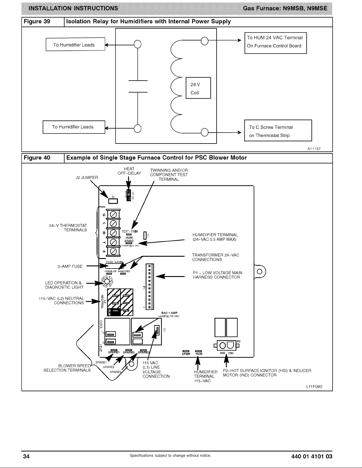
Figure 39 1Isolation Relay for Humidifiers with Internal Power Supply
Figure 40
To Humidifier Leads
To Humidifier Leads
O
24 V
Coil
O
Example of Single Stage Furnace Control for PSC Blower Motor
HEAT TWINNING AND/OR
J2 JUMPER
\
OFF-DELAY COMPONENT TEST
TERMINAL
To HUM 24 VAC Terminal
On Furnace Control Board
To C Screw Terminal
on Thermostat Strip
I
Al1157
24-V THERMOSTAT
TERMINALS
8-AMP FUSE
LED OPERATION &
DIAGNOSTIC LIGHT
115-VAC (L2) NEUTRAL
CONNECTIONS _'_
BLOWER SPEEE
SELECTION TERMINALS
TES&_W,.rlHUM _ HUMIDIFIER TERMINAL
115 VAC
(L1) LINE
VOLTAGE
CONNECTION
(24-VAC 0.5 AMP MAX)
TRANSFORMER 24-VAC
CONNECTIONS
P1 - LOW VOLTAGE MAIN
HARNESS CONNECTOR
XFMR HUM
HUMIDIFIER
TERMINAL
115-VAC
IND 1 HSI
P2-HOT SURFACE IGNITOR (HSI) & INDUCER
MOTOR (IND) CONNECTOR
L11F090
34 specificationssubjectto change without notice. 440 01 4101 03
Page 35
VENTING
NOTE: Planning for the venting system should be done in
conjunction with planning for the ductwork, drainage, and
furnace accessories, such as air cleaners and humidifiers.
Begin assembling the venting system AFTER the furnace is set
in place in the required orientation.
Venting for this furnace shall follow all Local codes for category
IV venting systems. This furnace is CSA approved for venting
with PVC/ABS DWV venting systems. This furnace is also CSA
approved for venting the M&G DuraVent ® PolyPro ®
polyproplylene venting systems.
NOTE: THESE INSTRUCTIONS DO NOT CONTAIN
DETAILED INSTALLATION INSTRUCTIONS FOR
POLYPROPYLENE VENTING SYSTEMS. Refer to the
polyproplylene venting system manufacturer's installation
instructions for the polyproplylene venting system installation.
NOTE: When using polypropylene venting systems, all venting
materials used, including the vent terminations, must be from
the same manufacturer.
Special Venting Requirements for Installations
in Canada
Installation in Canada must conform to the requirements of
CAN/CSA B149 code. Vent systems must be composed of
pipe, fittings, cements, and primers listed to ULC $636. The
special vent fittings, accessory concentric vent termination kits,
and accessory external drain trap available from the
manufacturer have been certified to ULC $636 for use with
those Royal Pipe and IPEX PVC vent components which have
been certified to this standard. In Canada, the primer and
cement must be of the same manufacturer as the vent system
- GVS-65 Primer (Purple) for Royal Pipe or IPEX System 636,
PVC/CPVC Primer, Purple Violet for Flue Gas Venting and
GVS-65 PVC Solvent Cement for Royal Pipe or IPEX System
636(1)t, PVC Cement for Flue Gas Venting, rated Class IIA, 65
deg C. must be used with this venting system - do not mix
primers and cements from one manufacturer with a vent
system from a different manufacturer. Follow the
manufacturer's instructions in the use of primer and cement
and never use primer or cement beyond its expiration date.
The safe operation, as defined by ULC $636, of the vent
system is based on following these installation instructions, the
vent system manufacturer's installation instructions, and proper
use of primer and cement. All fire stop and roof flashing used
with this system must be UL listed material. Acceptability under
Canadian standard CAN/CSA B149 is dependent upon full
compliance with all installation instructions. Under this
standard, it is recommended that the vent system be checked
once a year by qualified service personnel.
The authority having jurisdiction (gas inspection authority,
municipal building department, fire department, etc) should be
consulted before installation to determine the need to obtain a
permit.
*IPEX System 636 _' is a trademark of IPEX Inc.
Consignes sp_ciales pour rinstallation de
ventilation au Canada
L'installation faite au Canada dolt se conformer aux exigences
du code CAN/CSA B149-2010. Ce syst_me de ventillation dolt
se composer de tuyaux, raccords, ciments et appr_ts
conformes au ULC $636. La tuyauterie de ventilation des gaz,
ses accessoires, le terminal concentrique mural ainsi que
I'ensemble du drain de condensation exterieur fourni par le
fabricant de cette fournaise ont et6 certifies ULC $636 pour
I'application des composantes Royal Pipe, IPEX PVC qui sont
certifiees & ce standard. Au Canada, I'appr_t et le ciment
doivent _tre du m_me fabricant que le systeme d'evacuation.
L'appr_t GVS-65 (Purple) et le ciment-solvant GVS-65 doivent
_tre utitise avec les Royal Pipe. Systeme IPEX 636, appr_t
PVC/CPVC, Purple pour evacuation des gaz de combustion et
systeme IPEX 636(1)t, ciment PVC pour evacuation des gaz
de combustion, cote classe IIA, 65 deg C. doivent _tre utilises
avec le systeme d'evacuation IPEX 636 - Ne pas combiner I
'appr_t et le ciment d'un manufacturier avec un systeme
d'evacuation d'un manufacturier different.
Bien suivre les indications du manufacturier Iors de I'utilisation
de I'appr_t et du ciment et ne pas utitiser ceux-ci si la date
d'expiration est atteinte.
L'operation securitaire, tel que definit par ULC $636, du
systeme de ventilation est base sur les instructions
d'instaltation suivantes, ainsi que I'usage approprie de I'appr_t
et ciment. Tout arret feu et solin de toit utilises avec ce
systeme doivent _tre des materiaux listes UL L'acceptation du
standard Canadien CAN/CSA B149 est directement relie &
I'installation conforme aux instructions ci- haut mentionnees. Le
standard Canadien recommande I' inspection par un personel
qualifie et ce, une fois par annee.
Les autoritees ayant juridiction (inspecteurs de gas,
inspecteurs en b&timents, departement des incendies, etc)
devraient _tre consultees avant I'instatlation afin de determiner
si un permis est requis.
CARBON MONOXIDE POISONING HAZARD
Failure to follow the steps outlined below for each ap-
pliance connected to the venting system being placed
into operation could result in carbon monoxide poison-
ing or death.
Failure to follow the steps outlined below for each ap-
pliance connected to the venting system being placed
into operation could result in carbon monoxide poison-
ing or death.
1. Seal any unused openings in venting system.
2. Inspect the venting system for proper size and hori-
zontal pitch, as required in the National Fuel Gas
Code, ANSI Z223.1/NFPA 54 or the CSA B149.1 Nat-
ural Gas and Propane Installation Code and these in-
structions. Determine that there is no blockage or re-
striction, leakage, corrosion and other deficiencies,
which could cause an unsafe condition.
3. As far as practical, close all building doors and win-
dows and all doors between the space in which the ap-
pliance(s) connected to the venting system are loc-
ated and other spaces of the building.
4. Close fireplace dampers.
5. Turn on clothes dryers and any appliance not connec-
ted to the venting system. Turn on any exhaust fans,
such as range hoods and bathroom exhausts, so they
are operating at maximum speed. Do not operate a
summer exhaust fan.
6. Follow the lighting instructions. Place the appliance
being inspected into operation. Adjust the thermostat
so appliance is operating continuously.
7. Test for spillage from draft hood equipped appliances
at the draft hood relief opening after 5 minutes of main
burner operation. Use the flame of a match or candle.
8. If improper venting is observed during any of the
above tests, the venting system must be corrected in
accordance with the National Fuel Gas Code, ANSI
Z223.1/NFPA 54 and/or CSA B149.1 Natural Gas and
Propane Installation Code.
9. After it has been determined that each appliance con-
nected to the venting system properly vents when
tested as outlined above, return doors, windows, ex-
haust fans, fireplace dampers and any other gas-fired
burning appliance to their previous conditions of use.
440 01 4101 03 specificationssubjectto change without notice. 35
Page 36

General
If this furnace replaces a furnace that was connected to a vent
system or chimney, the vent or vent connectors of other
remaining appliances may need to be re-sized. Vent systems
or vent connectors of other appliances must be sized to the
minimum size as determined using appropriate table found in
the current edition of National Fuel Gas Code NFPA 54/ANSI
Z-223.1. In Canada, refer to CAN/CSA-B149.1
An abandoned masonry chimney may be used as a raceway
for properly insulated and supported combustion-air (when
applicable) and vent pipes. Each furnace must have its own set
of combustion-air and vent pipes and be terminated
individually, as shown in Figure 47 for Direct Vent (2-Pipe)
system, or Figure 48 for single-pipe or ventilated combustion
air option.
A furnace shall not be connected to a chimney flue serving a
separate appliance designed to burn solid fuel. Other gas
appliances with their own venting system may also use the
abandoned chimney as a raceway providing it is permitted by
local code, the current edition of the National Fuel Gas Code,
and the vent or liner manufacturer's installation instructions.
Care must be taken to prevent the exhaust gases from one
appliance from contaminating the combustion air of other gas
appliances.
Do not take combustion air from inside the chimney when using
ventilated combustion air or single-pipe vent option.
These furnaces can be vented as direct-vent (two-pipe),
ventilated combustion air, or non-direct (single-pipe) vent
system. Each type of venting system is described below.
Common venting between these furnaces or other appliances
is prohibited.
Materials
U.S.A.
Combustion air and vent pipe, fittings, primers, and solvents
must conform to American National Standards Institute (ANSI)
standards and American Society for Testing and Materials
(ASTM) standards. See Table 13 for approved materials for
use in the U.S.A. This furnace is also CSA approved for venting
with M&G DuraVent® PolyPro® polyproplylene venting
systems.
Canada
Special Venting Requirements for Installations in Canada
Installation in Canada must conform to the requirements of
CAN/CSA B149 code. Vent systems must be composed of
pipe, fittings, cements, and primers listed to ULC S636. M&G
DuraVent PolyPro polyproplylene venting systems are ULC
S636 listed.
NOTE: When using polypropylene venting systems, all venting
materials used, including the vent terminations, must be from
the same manufacturer.
Venting Systems
CARBON MONOXIDE POISONING HAZARD
Failure to follow the instructions outlined below for each
appliance being placed into operation could result in
carbon monoxide poisoning or death.
For all venting configurations for this appliance and other
gas appliances placed into operation for the structure,
3rovisions for adequate combustion, ventilation, and di-
lution air must be provided in accordance with:
U.S.A. Installations: Section 9.3 NFPA 54/ANSI
Z223.1 1-2009, Air for Combustion and Ventilation and
applicable provisions of the local building codes.
Canadian Installations: Part 8 of
CAN/CSA-B149.1-10. Venting Systems and Air
Supply for Appliances and all authorities having
jurisdiction.
RECOMMENDED SUPPORT FOR VENT
TERMINATIONS
It is recommended that sidewall vent terminations of
over 24 inches (0.6 M) in length or rooftop vent termin-
ations of over 36 inches (1 M) in length be supported
by EITHER the factory accessory vent termination kit
or field-supplied brackets or supports attached to the
structure. A factory accessory vent termination kit may
be used for direct vent terminations. Termination kits
are available for 2-in. or 3-in. pipe. See Table 12 for
available options.
Table 12
DirectVent (2-Pipe) Termination CombustionAir
TerminationKit System and Vent Pipes
2-in (51 mm) Concentric Single Penetration 1,1-1/2, 2, or 2-1/2
Vent Kit ofWall or Roof (25, 38, 51, 64 mm)
3-in (76 mm) Concentric Single Penetration 2-1/2, 3or 4
Vent Kit ofWall or Roof (64, 76, 102 mm)
2-in (51 mm) Termination Termination
Bracket Kit System (25, 38, 51, 64 mm)
3-in (76 mm) Termination Termination
Bracket System (64,76, 102mm)
Direct Vent / 2-Pipe System
In a direct-vent (2-pipe) system, all air for combustion is taken
directly from outdoor atmosphere, and all flue products are
discharged to outdoor atmosphere. Combustion-air and vent
pipes must terminate together in the same atmospheric
pressure zone, either through the roof (preferred) or a sidewall.
See Figure58 for references to clearances required by
National code authorities.
Vent Termination Kit for Direct
Vent (2-Pipe) Systems
Diam. Of
in,(mm)
2-Pipe 1, 1-1/2, 2, or 2-1/2
2-Pipe 2-1/2, 3 or 4
36 specificationssubjectto change without notice. 440 01 4101 03
Page 37

OPTIONAL CONFIGURATION FOR COMBUSTION
AIR INLET PIPE
In applications where there is a risk of excessive mois-
ture entering the combustion air inlet pipe, a moisture
trap may be added to the inlet pipe to help prevent
moisture from entering the furnace from the combus-
tion air inlet pipe. See Figure 49.
When sizing venting systems, the equivalent length of
the optional inlet pipe moisture trap must be taken into
account.
Ventilated Combustion Air Systems
In a ventilated combustion air option, the vent terminates and
discharges the flue products directly to the outdoors similar to a
direct vent system. See Figure 59 for references to clearances
required by National code authorities.
All air for combustion is piped directly to the furnace from a
space that is well ventilated with outdoor air (such as an attic or
crawl space) and the space is well isolated from the living
space or garage. Combustion air requirements for this option
are the same as the requirements for providing outside air for
combustion for a single pipe vent system. Refer to the "Air For
Combustion and Ventilation Section."
Provisions for adequate combustion, ventilation, and dilution air
must be provided in accordance with:
Non-Direct Vent (1-pipe) System
In a non direct-vent (1-pipe) system, all air for combustion is
taken from the area adjacent to furnace, and all flue products
are discharged to outdoor atmosphere. Air for combustion
must be supplied as described in the Air For Combustion and
Ventilation Section. Do not use an abandoned chimney to
supply outside air to the furnace. See Figure 59 for references
to clearances required by National code authorities.
A combustion air pipe to the outdoors is not required for a
single pipe vent system. A 12-in. (304 mm) long pipe with a
2-in. (50 mm Nominal Dimension- ND) tight radius 90 degree
elbow is required to be attached to the combustion air pipe
adapter on the furnace. (See Figure 55) This short inlet air pipe
helps to ensure stable combustion, as well as allow for sound
attenuation. To aid sound attenuation, point the inlet air pipe
away from occupants. An extra elbow and/or five feet (1.5 M) of
pipe may be used to accomplish the sound attenuation
function.
OPTIONAL VENTING BELOW THE FURNACE
The venting system may be positioned below the fur-
nace ONLY IF the factory accessory External Vent
Trap Kit is used. The External Vent Trap Kit is only
approved for PVC/ABS DWV venting systems.
CAREFULLY FOLLOW THE INSTRUCTIONS
PROVIDED WITH THE EXTERNAL VENT TRAP KIT
FOR LAYING OUT THE VENTING SYSTEM AND
THE DRAIN SYSTEM. The instructions included with
this furnace DO NOT APPLY to vent systems that are
located below the furnace
CARBON MONOXIDE POISONING HAZARD
Failure to follow the instructions outlined in Locating
the Vent Termination for each appliance being placed
into operation could result in carbon monoxide poison-
ing or death.
The instructions included with this furnace DO NOT
APPLY to vent systems that are located below the fur-
nace. CAREFULLY FOLLOW THE INSTRUCTIONS
PROVIDED WITH THE EXTERNAL VENT TRAP KIT
FOR LAYING OUT THE VENTING SYSTEM AND
THE DRAIN SYSTEM when all or part of the venting
system is placed below the furnace.
Proper configuration of the venting and drain system is
critical when placing all or part of the venting system
below the level of the furnace. VENT GASSES
COULD BE RELEASED FROM THE DRAINAGE
SYSTEM, if the instructions provided with the External
Vent Trap Kit are not followed.
440 01 4101 03 Specifications subject to change without notice. 37
Page 38

Table 13
ASTM
SPECIFICATION
(MARKEDON
MATERIAL)
D1527
D1785
D2235
D2241
D2466
D2468
D2564
D2661
D2665
F438
F441
F442
F493
F628
F656
F891
Approved Combustion-Air and Vent Pipe, Fitting and Cement Materials (U.S.A. Installation)
MATERIAL PIPE FITTINGS
ABS Pipe -
PVC Pipe -
For ABS - -
PVC Pipe -
PVC - Fittings
ABS - Fittings
For PVC - -
ABS Pipe Fittings
PVC Pipe Fittings
CPVC - Fittings
CPVC Pipe -
CPVC Pipe -
For CPVC - -
ABS Pipe
For PVC
PVC Pipe
SOLVENT CEMENT AND
PRIMERS
Solvent Cement
Solvent Cement
Solvent Cement
Primer
DESCRIPTION
Schedule-40
Schedule-40
For ABS
SDR-21 & SDR-26
Schedule-40
Schedule-40
For PVC
DWV at Schedule-40 IPS sizes
DWV
Schedule-40
Schedule-40
SDR
For CPVC
Cellular Core DWV at Schedule-40 IPS
sizes
For PVC
Cellular Core Schedule-40 & DWV
Figure 41
Attach gaskets to vent pipe and combustion air adapters
Vent Coupling and Adapter with
Gaskets
L
Vent Couplingand Adapter
Al1314
Figure 42
Vent Pipe Flush with Adaptor
VENT PIPE ADAPTER WITH GASKET
INSTALLED ON FURNACE VENT
PIPE IS CUT FLUSH WITH TOP OF
ADAPTER.
A11339A
Figure 43 _Vent Pipe Flush Showing Coupling
ALIGN NOTCHES IN VENT PIPE COUPLING OVER STAND-
OFF ON ADAPTER. TORQUE LOWER CLAMP 15 LB-IN. WHEN
REMAINING VENT PIPE IS INSTALLED, TORQUE UPPER
CLAMP TO 15 LB-IN.
A11889B
38 Specificationssubjectto change without notice. 440 01 4101 03
Page 39
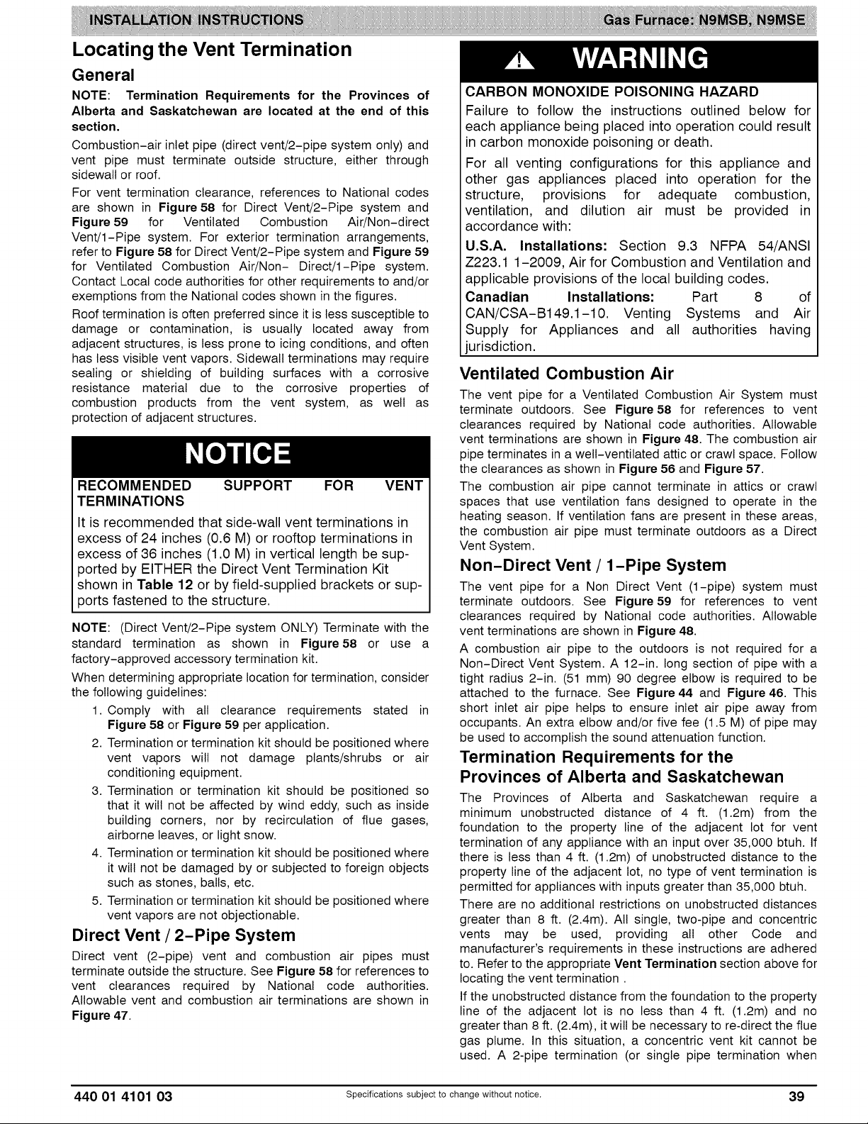
Locating the Vent Termination
General
NOTE: Termination Requirements for the Provinces of
Alberta and Saskatchewan are located at the end of this
section.
Combustion-air inlet pipe (direct vent/2-pipe system only) and
vent pipe must terminate outside structure, either through
sidewall or roof.
For vent termination clearance, references to National codes
are shown in Figure 58 for Direct Vent/2-Pipe system and
Figure 59 for Ventilated Combustion Air/Non-direct
Vent/I-Pipe system. For exterior termination arrangements,
refer to Figure 58 for Direct Vent/2-Pipe system and Figure 59
for Ventilated Combustion Air/Non- Direct/I-Pipe system.
Contact Local code authorities for other requirements to and/or
exemptions from the National codes shown in the figures.
Roof termination is often preferred since it is less susceptible to
damage or contamination, is usually located away from
adjacent structures, is less prone to icing conditions, and often
has less visible vent vapors. Sidewall terminations may require
sealing or shielding of building surfaces with a corrosive
resistance material due to the corrosive properties of
combustion products from the vent system, as well as
protection of adjacent structures.
RECOMMENDED SUPPORT FOR VENT
TERMINATIONS
It is recommended that side-wall vent terminations in
excess of 24 inches (0.6 M) or rooftop terminations in
excess of 36 inches (1.0 M) in vertical length be sup-
ported by EITHER the Direct Vent Termination Kit
shown in Table 12 or by field-supplied brackets or sup-
3orts fastened to the structure.
NOTE: (Direct Vent/2-Pipe system ONLY) Terminate with the
standard termination as shown in Figure58 or use a
factory-approved accessory termination kit.
When determining appropriate location for termination, consider
the following guidelines:
1. Comply with all clearance requirements stated in
Figure 58 or Figure 59 per application.
2. Termination or termination kit should be positioned where
vent vapors will not damage plants/shrubs or air
conditioning equipment.
3. Termination or termination kit should be positioned so
that it will not be affected by wind eddy, such as inside
building corners, nor by recirculation of flue gases,
airborne leaves, or light snow.
4. Termination or termination kit should be positioned where
it will not be damaged by or subjected to foreign objects
such as stones, balls, etc.
5. Termination or termination kit should be positioned where
vent vapors are not objectionable.
Direct Vent / 2-Pipe System
Direct vent (2-pipe) vent and combustion air pipes must
terminate outside the structure. See Figure 58 for references to
vent clearances required by National code authorities.
Allowable vent and combustion air terminations are shown in
Figure 47.
CARBON MONOXIDE POISONING HAZARD
Failure to follow the instructions outlined below for
each appliance being placed into operation could result
in carbon monoxide poisoning or death.
For all venting configurations for this appliance and
other gas appliances placed into operation for the
structure, provisions for adequate combustion,
ventilation, and dilution air must be provided in
accordance with:
U.S.A. Installations: Section 9.3 NFPA 54/ANSI
Z223.1 1-2009, Air for Combustion and Ventilation and
applicable provisions of the local building codes.
Canadian Installations: Part 8 of
CAN/CSA-B149.1-10. Venting Systems and Air
Supply for Appliances and all authorities having
jurisdiction.
Ventilated Combustion Air
The vent pipe for a Ventilated Combustion Air System must
terminate outdoors. See Figure58 for references to vent
clearances required by National code authorities. Allowable
vent terminations are shown in Figure 48. The combustion air
pipe terminates in a welt-ventilated attic or crawl space. Follow
the clearances as shown in Figure 56 and Figure 57.
The combustion air pipe cannot terminate in attics or crawl
spaces that use ventilation fans designed to operate in the
heating season. If ventilation fans are present in these areas,
the combustion air pipe must terminate outdoors as a Direct
Vent System.
Non-Direct Vent / 1-Pipe System
The vent pipe for a Non Direct Vent (1-pipe) system must
terminate outdoors. See Figure59 for references to vent
clearances required by National code authorities. Allowable
vent terminations are shown in Figure 48.
A combustion air pipe to the outdoors is not required for a
Non-Direct Vent System. A 12-in. long section of pipe with a
tight radius 2-in. (51 mm) 90 degree elbow is required to be
attached to the furnace. See Figure 44 and Figure 46. This
short inlet air pipe helps to ensure inlet air pipe away from
occupants. An extra elbow and/or five fee (1.5 M) of pipe may
be used to accomplish the sound attenuation function.
Termination Requirements for the
Provinces of Alberta and Saskatchewan
The Provinces of Alberta and Saskatchewan require a
minimum unobstructed distance of 4 ft. (1.2m) from the
foundation to the property line of the adjacent lot for vent
termination of any appliance with an input over 35,000 btuh. If
there is less than 4 ft. (1.2m) of unobstructed distance to the
property line of the adjacent lot, no type of vent termination is
permitted for appliances with inputs greater than 35,000 btuh.
There are no additional restrictions on unobstructed distances
greater than 8 ft. (2.4m). All single, two-pipe and concentric
vents may be used, providing all other Code and
manufacturer's requirements in these instructions are adhered
to. Refer to the appropriate Vent Termination section above for
locating the vent termination.
If the unobstructed distance from the foundation to the property
line of the adjacent lot is no less than 4 ft. (1.2m) and no
greater than 8 ft. (2.4m), it will be necessary to re-direct the flue
gas plume. In this situation, a concentric vent kit cannot be
used. A 2-pipe termination (or single pipe termination when
440 01 4101 03 Specificationssubjectto change without notice. 39
Page 40
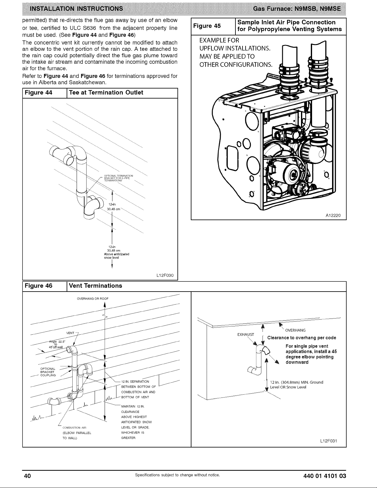
permitted) that re-directs the flue gas away by use of an elbow
or tee, certified to ULC S636 from the adjacent property line
must be used. (See Figure 44 and Figure 46)
The concentric vent kit currently cannot be modified to attach
an elbow to the vent portion of the rain cap. A tee attached to
the rain cap could potentially direct the flue gas plume toward
the intake air stream and contaminate the incoming combustion
air for the furnace.
Refer to Figure 44 and Figure 46 for terminations approved for
use in Alberta and Saskatchewan.
Sample Inlet Air Pipe Connection
Figure 45 for Polypropylene Venting Systems
EXAMPLE FOR
UPFLOW INSTALLATIONS.
MAY BEAPPLIED TO
OTHERCONFIGURATIONS.
Figure 44 ITee at Termination Outlet
I
OPTIONALTERMINATION
BRACKETFOR2 PIPE
TERMINATIONS _
12-in
30.48 cm
Above anticipated
snow level
\
A12220
Figure 46 IVent Terminations
COMBUSTION AIR
(ELBOW PARALLEL
TO WALL)
SEPARATION
LEVEL OR GRADE,
WHICHEVER IS
GREATER
L12F030
J
OVERHANG
Clearance to overhang per code
For single pipe vent
degree elbow pointing
applications, install a 45
......"'_ downward
L12F031
40 Specificationssubjectto change without notice. 440 01 4101 03
Page 41
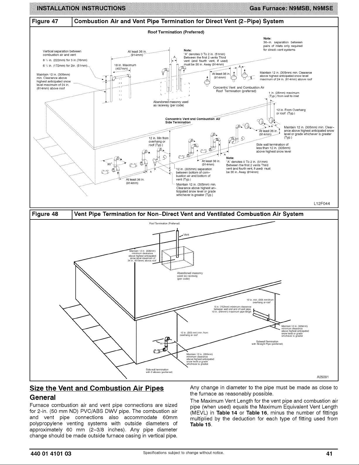
Figure47 _Combustion Air and Vent Pipe Termination for Direct Vent (2-Pipe) System
Roof Termination (Preferred)
Note:
36-in separation between
pairs of inlets only required
for direct-vent systems
Maintain 12 in. (3O5mm) min Clearance
above highest anticipated snow level
maximum of 24 in. (614ram) above roof
1 in (25mm) maximum
(Typ.) from wall to inlet
12 in. From Overhang
or roof (Typ.)
(914rain)_
/ ....
Side wall termination of
less than 12 in (3O5mm)
above highest snow level
Vertical separation between
combustion air and vent
8 ;,_ in (222mm) for 3 in (76ram)
6 in. (172mm) for 2in. (51mm) ,
Maintain 12 in (305mm) \\
min. Clearance above
highest anticipated snow
level maximum of 24 in.
(614mm) above roof
\\\\\
J
A east36 n ............ q
................ (914mm) ....... / I'A4
,\
\,
18 in. Maximum
(914mm)
i
i
Abandoned masonry used
as raceway (per code)
Concentric Vent and Combustion Air
Side Termination
12 in. Min from
overhang or _
roof (Typ.)
Note:
"A" denotes 0 To 2 in (51 mm)
Between the first 2 vents Third
vent (and fourth vent, if used)
I /
must be 36 in Away (914mm)
(305ram) separation
between bottom of com-
bustion air and bottom of
vent (Typ.)
Maintain 12 in. (305mm) rain.
Clearance above highest an-
ticipated snow level or grade
whichever is greater (Typ)
Concentric Vent and Combustion Air
Roof Termination (preferred)
Note:
(914mm)
"A" denotes 0 To 2 in (51ram)
Between the first 2 vents Third
vent (and fourth vent, if used) must
be 36 in. Away (914mm)
Maintain 12 in (3O5mm) min Clear-
ance above highest anticipated snow
level or grade whichever is greater
(Typ)
L12F044
Figure 48
Vent Pipe Termination for Non-Direct Vent and Ventilated Combustion Air System
Roof Termination (Preferred)
Maintain 12 in (3O5mm)
minimum clearance
above highest anticipated
snow level maximum of
24 _n (61 gram) above roof
Abandoned masonry
used as raceway
(percode)
12 in rain (305 ram)from
overhang or roof
Sidewall Termination
w_th Straight P_pe (preferred)
Maintain 12 in (3O5mm)
minimumclearance
above highest anticipated
whichever is greater
Side wall terminaSon
w_h 2 elbows (preferred)
Maintain 12 in (3O5mm)
minimum clearance
above highest anticipated
snow level or grade
whichever _s greater
6 in 152mm) minimum clearance
bergen wa I and end o vent pipe
10 in (254mm) m_lmum pipe lengh
A05091
Size the Vent and Combustion Air Pipes
General
Furnace combustion air and vent pipe connections are sized
for 2-in. (50 mm ND) PVC/ABS DWV pipe. The combustion air
and vent pipe connections also accommodate 60mm
polypropylene venting systems with outside diameters of
Any change in diameter to the pipe must be made as close to
the furnace as reasonably possible.
The Maximum Vent Length for the vent pipe and combustion air
pipe (when used) equals the Maximum Equivalent Vent Length
(MEVL) in Table 14 or Table 16, minus the number of fittings
multiplied by the deduction for each type of fitting used from
Table 15.
approximately 60 mm (2-3/8 inches). Any pipe diameter
change should be made outside furnace casing in vertical pipe.
440 01 4101 03 Specificationssubjectto change without notice. 41
Page 42

OPTIONAL CONFIGURATION FOR COMBUSTION
AIR INLET PIPE
In applications where there is a risk of excessive mois-
ture entering the combustion air inlet pipe, a moisture
trap may be added to the inlet pipe to help prevent
moisture from entering the furnace from the combus-
tion air inlet pipe. See Figure 49.
When sizing venting systems, the equivalent length of
the optional moisture trap (15 feet/5 M) must be taken
into account
Optional Combustion Air Inlet
Moisture Trap
As an option to prevent moisture from trickling into the furnace
vestibule, a trap can be installed in the intake air pipe near the
furnace. Connecting a drain line to the trap is optional as trace
amounts of moisture will evaporate into the intake air stream. If
the combustion air inlet is located near a moisture exhaust
duct, or there are other concerns of excessive moisture being
drawn into the combustion air inlet, it is encouraged to connect
a drain line to the trap.
The trap can be constructed from a running tee of the same
diameter of the intake air pipe with EITHER a removable cap
attached to a 6-inch long pipe connected to the tee or the
External vent Trap Kit to help prevent contaminants from
entering the furnace. See Figure 49.
The External Vent Trap Kit accessory may be used as a trap for
the combustion air inlet pipe if a large amount of moisture must
be removed. The drain line may be connected to the same
drain as the furnace condensate and the evaporator coil
condensate line ONLY if the inlet air trap drain and the
evaporator coil drain empty into an open segment of pipe
above the drain, See Figure 12. When using the External Vent
Trap Kit, refer to those instructions for proper drain
connections.
The tee may also be connected to the intake air pipe on the
side of the casing. See Figure 49.
In any configuration, it will be necessary to add the equivalent
length of the tee (15 feet/5 M) to the Total Equivalent Vent
Length of the venting system.
ADDITIONAL INFORMATION FOR POLYPROPYL-
ENE VENTING SYSTEMS
Polypropylene venting systems include flexible vent
pipe. These flexible vent pipes have a different equi-
valent vent length than straight sections of PVC/ABS
DWV vent pipe. Be sure to make the appropriate de-
ductions from the Maximum Equivalent Vent Length
(MEVL), or additions to the Total Equivalent Vent
Length (TEVL), when applying flexible vent pipes in
polypropylene venting systems. See the polypropylene
vent system manufacturer's installation instructions for
details.
When using metric-sized venting systems, use these
equivalencies for obtaining the proper MEVL from the
Tables:
Use 2" Vent Tables for 60mm (o.d.) vent systems
Use 3" Vent Tables for 80mm (o.d.) vent systems
Use 4" Vent Tables for 100mm (o.d.) vent systems
The measured length of pipe used in a single or 2-pipe
termination is included in the total vent length. Include
deductions from the Maximum Equivalent Vent Length (MEVL)
contained in the Venting Tables for elbows and flexible vent
pipe. Factory accessory concentric vent terminations, or pipe
lengths and elbows used for "standard" vent terminations (see
vent termination figures associated with Table14) do not
require a deduction from the Maximum Equivalent Vent Length.
Include a deduction for a Tee when used for Alberta and
Saskatchewan terminations.
NOTE: Polypropylene venting systems MAY require additional
deductions from the MEVL, or additions to the TEVL, for vent
terminations and flexible pipe sections. See the polypropylene
venting system manufacturer's instructions for details on
equivalent lengths of vent terminations and flexible vent pipes,
and for calculating total vent lengths.
To calculate the Total Equivalent Vent Length (TEVL) of the
venting system:
1. Measure the individual distance from the furnace to the
termination for each pipe.
2. Count the number of elbows for each pipe.
3. For each pipe, multiply the number of elbows by the
equivalent length for the type of elbow used. Record the
equivalent length of all the elbows for each pipe.
4. If a Tee is used on the termination (Alberta and
Saskatchewan, when required), record the equivalent
length of the Tee used.
5. Calculate Total Equivalent Vent Length by adding the
equivalent lengths of the fittings to the lengths of the
individual vent and combustion air pipes.
6. When using polypropylene venting systems with flexible
vent pipes, perform adjustments for the equivalent length
of the flexible vent pipe to the calculated total equivalent
venting system length. See the polypropylene vent
system manufacturer's instructions for details.
7. Select a diameter of vent pipe from Table 14 and
Table 16 and note the Maximum Equivalent Vent Length
(MEVL) shown for that application for that specific
furnace input size. Compare the Total Equivalent Vent
Length (TEVL) to the MEVL:
a. If the Total Equivalent Vent Length is shorter than the
Maximum Equivalent Vent Length for the diameter of
pipe chosen, then that diameter of pipe selected may
be used.
b. If the Total Vent Length is longer than the Maximum
Equivalent Vent Length for the diameter of pipe
chosen, that diameter pipe MAY NOT be used for
venting the furnace. Try the next larger diameter pipe.
NOTE: If the calculated Total Equivalent Vent Lengths results
in different diameter pipes for the vent and combustion air,
select the larger diameter for both pipes.
NOTE: If the Maximum Vent Length for diameter of the pipe
selected is longer than the measured length and the equivalent
length of all the fittings and terminations (TEVL), recalculate
Total Equivalent Vent Length using the next smaller diameter. If
the Maximum Vent Length is still longer than the longer TEVL
of the vent pipe or combustion air pipe, then that diameter of
pipe selected may be used.
When installing vent systems with pipe lengths of 10 ft. (3.0 M)
or less, use the smallest allowable pipe diameter. Using pipe
size greater than required for short venting systems may result
in loss of efficiency, incomplete combustion, flame disturbance,
or flame sense lockout.
For vent systems longer than 10 ft. (3.0 M), any larger diameter
shown in Table 14 or Table 16 for that size model may be
used.
42 Specificationssubjectto change without notice. 440 01 4101 03
Page 43

Figure 49
Optional Combustion Air Inlet Moisture Trap
® ®
i
TO CODE-APPROVED DRAIN OR CONDENSATE PUMP
N
Representative drawing only, some models may vary in appearance
Combustion Air and Vent Piping Insulation
Guidelines
NOTE: Use closed cell, neoprene insulation or equivalent.
The vent pipe may pass through unconditioned areas. The
amount of exposed pipe allowed is shown in Table 17.
1. Using winter design temperature (used in load
calculations), find appropriate temperature for your
application and furnace model.
2. Determine the amount of total and exposed vent pipe.
3. Determine required insulation thickness for exposed pipe
length(s).
4. When combustion air inlet piping is installed above a
suspended ceiling, the pipe MUST be insulated with
moisture resistant insulation such as Armafiex or other
equivalent type of insulation.
5. Insulate combustion air inlet piping when run in warm,
humid spaces.
6. Install the insulation per the insulation manufacturer's
installation instructions.
NOTE: Pipe length (ft / M) specified for maximum pipe lengths
located in unconditioned spaces (See Table 17) cannot exceed
total allowable pipe length as calculated from Table 14 through
Table 16.
® ®
® ®
o-o
Configure the Furnace
CARBON MONOXIDE POISONING HAZARD
Failure to follow this warning could result in personal
injury or death.
To route the vent pipe and combustion air pipe through
the furnace, the manufacturer supplied kit must be
used. Failure to properly seal the blower compartment
from the furnace vestibule could result in the
circulation of carbon monoxide throughout the
structure. The vent pipe and combustion air pipe must
be a continuous pipe while passing through the blower
compartment. Seals supplied in this kit must be
installed per the instructions provided. Follow all
procedures outlined in these instructions.
Install the Vent and Combustion Air Pipes
With the furnace installed in the required position, remove the
desired knockouts from the casing. It will be necessary to
remove one knockout for the vent pipe and the other knockout
for the combustion air connection. (See Figure 13)
Use a flat blade screwdriver and tap on the knockout on
opposite sides, where the knockout meets the casing. Fold the
knockout down with duct pliers and work the knockout back
and forth until it is removed. Trim any excess metal from the
knockout with tin snips.
L12F028
440 01 4101 03 Specifications subject to change without notice. 43
Page 44
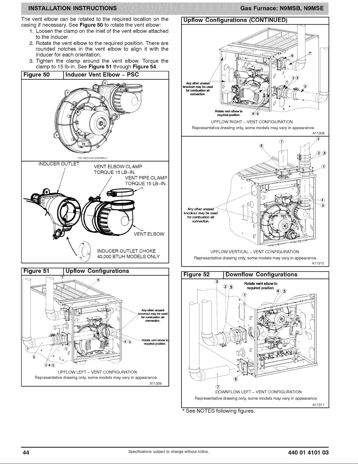
The vent elbow can be rotated to the required location on the
casing if necessary. See Figure 50 to rotate the vent elbow:
1. Loosen the clamp on the inlet of the vent elbow attached
to the inducer.
2. Rotate the vent elbow to the required position. There are
rounded notches in the vent elbow to align it with the
inducer for each orientation.
3. Tighten the clamp around the vent elbow. Torque the
clamp to 15 Ib-in. See Figure 51 through Figure 54.
Figure 50 1Inducer Vent Elbow - PSC
Upflow Configurations (CONTINUED)
Anyother unused
le'u_kentmay bo used
for combustionair
cennec_en.
INDUCEROUTLET
Figure 51
/i'
PSC INDUCER ASSEMBLY
VENT ELBOW CLAMP
TORQUE 15 LB-IN.
\
INDUCER OUTLET CHOKE
40,000 BTUH MODELS ONLY
Upflow Configurations
Y
VENT PIPE CLAMP
TORQUE 15 LB-IN.
VENT ELBOW
Rotate vent elbow to
require_:l posi_en.
UPFLOW RIGHT - VENT CONFIGURATION
Representative drawing only, some models may vary in appearance.
J
J
/
/
j/-_/J
Any other unused <z
knockout may be used tlI
for combustion air ',
connection.
,, 0
\\\
UPFLOW VERTICAL - VENT CONFIGURATION
Representative drawing only, some models may vary in appearance.
Figure 52 I Downflow Configurations
_3_ Rotate vent elbow to
i F, ,_F,,_,
......... ! _2__5_ required position.
/ ...........
Al1308
Al1310
I
Any _ _used
for cecnbustten air
o_r_actten.
" - Rotate vent elbow to
required position.
d2b_®
UPFLOW LEFT - VENT CONFIGURATION
Representative drawing only, some models may vary in appearance.
Al1309
Representative drawing only, some models may vary in appearance.
@
DOWNFLOW LEFT - VENT CONFIGURATION
Al1311
* See NOTES following figures.
44 specificationssubjectto change without notice. 440 01 4101 03
Page 45
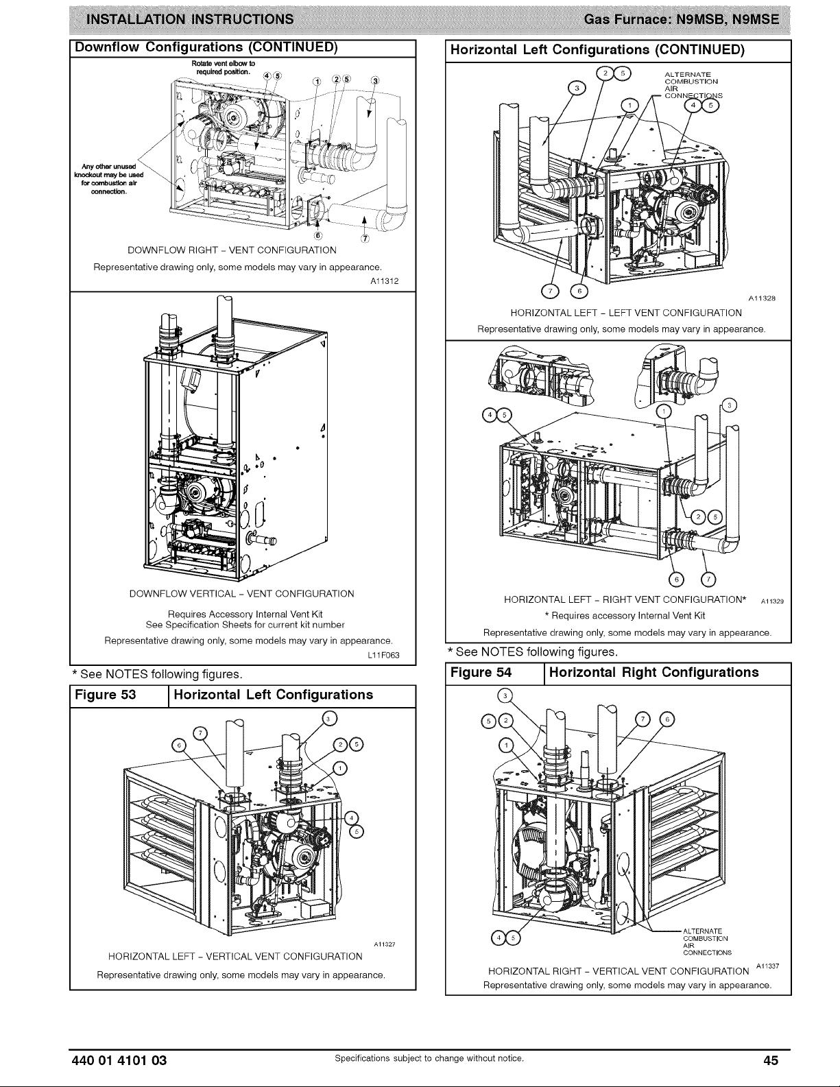
Downflow Configurations (CONTINUED)
Rotate vent elbow to
required position,
DOWNFLOW RIGHT - VENT CONFIGURATION
Representative drawing only, some models may vary in appearance.
Alt3t2
Horizontal Left Configurations (CONTINUED)
ALTERNATE
COMBUSTION
AIR
HORIZONTAL LEFT - LEFT VENT CONFIGURATION
Representative drawing only, some models may vary in appearance.
©
A11328
DOWNFLOW VERTICAL - VENT CONFIGURATION
Requires Accessory Internal Vent Kit
See Specification Sheets for current kit number
Representative drawing only, some models may vary in appearance.
* See NOTES following figures.
Figure 53 _Horizontal Left Configurations
L11F063
I
HORIZONTAL LEFT - RIGHT VENT CONFIGURATION* Al1329
* Requires accessory Internal Vent Kit
Representative drawing only, some models may vary in appearance.
* See NOTES following figures.
Figure 54 1Horizontal Right Configurations
COMBUSTION
CONNECTIONS
AI 1337
HORIZONTAL LEFT - VERTICAL VENT CONFIGURATION
Representative drawing only, some models may vary in appearance.
AI1327
HORIZONTAL RIGHT - VERTICAL VENT CONFIGURATION
Representative drawing only, some models may vary in appearance.
440 01 4101 03 Specificationssubjectto change without notice. 45
Page 46

Horizontal Right Configurations (CONTINUED)
HORIZONTAL RIGHT - LEFT VENT CONFIGURATION
Representative drawing only, some models may vary in appearance.
ALTERNATE
COMBUSTION
AIR
A11336
Installing the Vent Pipe Adapter and
Combustion Air Pipe Adapter
CARBON MONOXIDE POISONING HAZARD
Failure to follow this warning could result in personal
injury or death.
To route the vent pipe and combustion air pipe through
the furnace, the manufacturer supplied kit must be
used. Failure to properly seal the blower compartment
from the furnace vestibule could result in the
circulation of carbon monoxide throughout the
structure. The vent pipe and combustion air pipe must
be a continuous pipe while passing through the blower
compartment. Seals supplied in this kit must be
installed per the instructions provided. Follow all
3rocedures outlined in these instructions.
CARBON MONOXIDE POISONING HAZARD
Failure to follow this warning could result in personal
injury or death.
DO NOT use cement to join polypropylene venting
systems. Follow the polypropylene venting system
manufacturer,s instructions for installing polypropylene
venting systems.
HORIZONTAL RIGHT - RIGHT VENT CONFIGURATION
Representative drawing only, some models may vary in appearance.
* See NOTES following figures.
NOTES:
1. Attach vent pipe adapter with gasket to furnace casing.
2. Align notches in rubber coupling over standoffs on
adapter. Slide clamps over the coupling.
3. Slide vent pipe through adapter and coupling into vent
elbow.
4. Insert vent pipe into vent elbow.
5. Torque all clamps 15-lb.-in.
6. Attach combustion air pipe adapter with gasket to
furnace.
7. Attach combustion air pipe to adapter with silicone. Pilot
drill a ]/8-in. Hole in adapter and secure with a #7 x
]/2-in. Sheet metal screw.
A11335
NOTE: The rubber coupling that attaches to the vent pipe
adapter must be used. The adapter seals the vent pipe to the
casing and reduces the strain on the vent elbow attached to the
inducer.
1. Apply the gaskets to the vent pipe and combustion air
pipe adapters. If supplied, remove and discard round
center "slug" from interior of gasket. See Figure 41.
NOTE: The vent pipe adapter can be distinguished from the
inlet pipe adapter by the absence of an internal pipe-stopping
ring. The vent pipe can pass through the vent pipe adapter; it
cannot pass through the inlet pipe adapter.
2. Align the screw holes in the plastic vent pipe adapter with
the dimples in the casing.
3. Pilot drill the screw holes for the adapter in the casing
and attach the vent pipe adapter to the furnace with
sheet metal screws
4. Slide the end of the rubber vent coupling with notches in
it over the standoffs on the vent pipe adapter.
5. Insert a length of vent pipe through the coupling into the
outlet of the vent elbow.
6. Tighten the clamp around the outlet of the vent elbow.
Torque the clamp to 15 Ib-in.
The following instructions are for PVC/ABS DWV vent
piping, only. DO NOT USE THESE TECHNIQUES FOR
POLYPROPYLENE VENT PIPING SYSTEMS. See the
polypropylene vent system manufacturer's instructions
for installing polypropylene venting systems.
46 specificationssubjectto change without notice. 440 01 4101 03
Page 47

Installtheremainingventandcombustionairpipesasshown
below.Itisrecommendedthatallpipesbecut,prepared,and
preassembledbeforepermanentlycementinganyjoint.
1.Workingfromfurnaceto outside,cutpipeto required
length(s).
2.De-burrinsideandoutsideofpipe.
3.Chamferoutsideedgeofpipeforbetterdistributionof
primerandcement.
4.Cleananddryallsurfacestobejoined.
5.Checkdryfitofpipeandmarkinsertiondepthonpipe.
6.Inserttheventpipeintotheventelbow.
7.Torqueclamponventelbow15Ib-in.
8.Torqueclamponventcoupling15Ib-in.
9.Insertthecombustionairpipeintotheadapter.
10.Pilotdrilla screwholethroughtheadapterintothe
combustionairpipeandsecurethepipetotheadapter
with sheetmetalscrews.DO NOTDRILLINTO
POLYPROPYLENEVENTPIPES.Usean optional
accessoryventcoupling,ifneeded.
11.Sealaroundthecombustionairpipewithsiliconeorfoil
tape. SILICONESEALERSMAY NOT BE
APPROPRIATEFOR POLYPROPYLENEVENT
SYSTEMS.SEEPOLYPROPYLENEVENTSYSTEM
MANUFACTRUER'SINSTRUCTIONS.
12.Afterpipeshavebeencutandpreassembled,apply
generouslayerofcementprimertopipefittingsocket
and endof pipeto insertionmark.Quicklyapply
approvedcementtoendofpipeandfittingsocket(over
primer).Applycementinalight,uniformcoatoninsideof
socketto preventbuildupof excesscement.Apply
secondcoat.DONOTCEMENTPOLYPROPYLENE
FITTINGS.
13.Whilecementis stillwet,twistpipeintosocketwith
1/4-in.turn.Besurepipeis fullyinsertedintofitting
socket.
14.Wipeexcesscementfromjoint.A continuousbeadof
cementwillbevisiblearoundperimeterofa properly
madejoint.
15.Handlepipejointscarefullyuntilcementsets.
16.Horizontalportionsof the ventingsystemshallbe
supportedto preventsagging.Supportcombustionair
pipingandventpipingaminimumofevery5ft.(1.5M)[3
ft. (.91M)forSDR-21or -26 PVC]usingperforated
metalhangingstraporcommerciallyavailablehangars
designedtosupportplasticpipe.
17.Preventcondensatefromaccumulatinginthepipesby
slopingthe combustionair pipingandventpiping
downwardtowardsfurnacea minimumof 1/4-in.per
linearft.withnosagsbetweenhangers.
18.Completetheventandcombustionairpipeinstallation
byconnectingtotheconcentricventorbyinstallingthe
requiredterminationelbowsasshowninFigure47and
Figure 48, Alberta Figure 44 and Figure 46. For
ventilated combustion air terminations, refer to
Figure 48, Alberta Figure 44 and Figure 46.
19. Use appropriate methods to seal openings where
combustion air pipe and vent pipe pass through roof or
sidewall.
CARBON MONOXIDE POISONING HAZARD
Failure to follow this warning could result in personal
injury or death.
DO NOT use cement to join polypropylene venting
systems. Follow the polypropylene venting system
manufacturer's instructions for installing polypropylene
venting systems.
Optional Installation of the Vent Pipe
NOTE: DO NOT USE THIS TECHNIQUE FOR
POLYPROPYLENE VENTING SYSTEMS.
This option provides a disconnect point for the vent pipe. The
vent pipe must be cemented to the plastic vent pipe adapter to
maintain a sealed vestibule. See Figure 42 and Figure 43
1. Insert a length of vent pipe through the casing into the
outlet of the vent elbow.
2. Slide the plastic vent pipe adapter over the length of the
vent pipe down to the furnace casing. Mark the pipe
where it is flush with the outlet of the adapter.
3. Remove the pipe from the furnace and the adapter and
cut off any excess pipe.
4. Clean and prime the end of the pipe that is flush with the
vent adapter with a primer that is appropriate for the type
of pipe being used.
5. Re-insert the pipe through the casing into the vent
elbow.
6. Tighten the clamp around the outlet of the vent elbow.
Torque the clamp to 15 Ib-in.
7. Apply cement to the end of the pipe and to the inside of
the plastic vent adapter.
8. Slide the adapter over the vent pipe and align the screw
holes in the adapter with the dimples in the furnace
casing,
9. Pilot drill 1/8-in. screw holes for the adapter in the casing
and secure the adapter to the furnace with sheet metal
screws.
10. Loosen the clamps on the rubber vent coupling.
11. Slide the end of the coupling with notches in it over the
standoffs in the vent pipe adapter.
12. Tighten the clamp of the coupling over the vent pipe
adapter. Torque the lower clamp around the vent pipe
adapter to 15 Ib-in.
13. Pilot drill a 1/8-in. hole in the combustion air pipe
adapter.
14. Complete the vent and combustion air pipe as shown in
"Install the Vent and Combustion Air Pipe"
FOR POLYPROPYLENE VENTING SYSTEMS
When using polypropylene venting systems, all venting
materials used, including the vent terminations, must
be from the same manufacturer.
440 01 4101 03 Specificationssubjectto change without notice. 47
Page 48
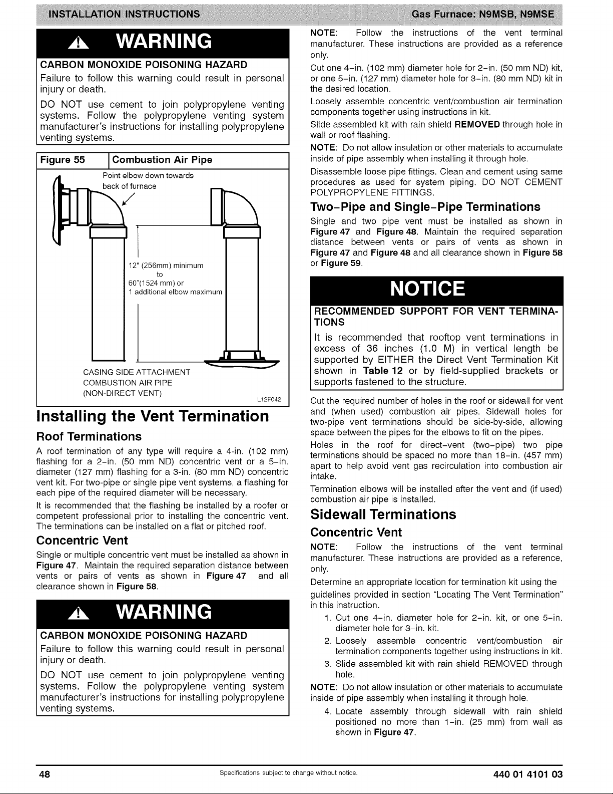
CARBON MONOXIDE POISONING HAZARD
Failure to follow this warning could result in personal
injury or death.
DO NOT use cement to join polypropylene venting
systems. Follow the polypropylene venting system
manufacturer's instructions for installing polypropylene
venting systems.
Figure 55
Combustion Air Pipe
Point elbowdown towards
back of furnace
/
12" (256mm) minimum
to
60"(1524 mm) or
1 additional elbow maximum
CASING SIDE ATTACHMENT
COMBUSTION AIR PIPE
(NON-DIRECT VENT)
Installing the Vent Termination
Roof Terminations
A roof termination of any type will require a 4-in. (102 mm)
flashing for a 2-in. (50 mm ND) concentric vent or a 5-in.
diameter (127 mm) flashing for a 3-in. (80 mm ND) concentric
vent kit. For two-pipe or single pipe vent systems, a flashing for
each pipe of the required diameter will be necessary.
It is recommended that the flashing be installed by a roofer or
competent professional prior to installing the concentric vent.
The terminations can be installed on a flat or pitched roof.
Concentric Vent
Single or multiple concentric vent must be installed as shown in
Figure 47. Maintain the required separation distance between
vents or pairs of vents as shown in Figure 47 and all
clearance shown in Figure 58.
CARBON MONOXIDE POISONING HAZARD
Failure to follow this warning could result in personal
injury or death.
DO NOT use cement to join polypropylene venting
systems. Follow the polypropylene venting system
manufacturer's instructions for installing polypropylene
venting systems.
Lt2F042
NOTE: Follow the instructions of the vent terminal
manufacturer. These instructions are provided as a reference
only.
Cut one 4-in. (102 mm) diameter hole for 2-in. (50 mm ND) kit,
or one 5-in. (127 mm) diameter hole for 3-in. (80 mm ND) kit in
the desired location.
Loosely assemble concentric vent/combustion air termination
components together using instructions in kit.
Slide assembled kit with rain shield REMOVED through hole in
wall or roof flashing.
NOTE: Do not allow insulation or other materials to accumulate
inside of pipe assembly when installing it through hole.
Disassemble loose pipe fittings. Clean and cement using same
procedures as used for system piping. DO NOT CEMENT
POLYPROPYLENE FITTINGS.
Two-Pipe and Single-Pipe Terminations
Single and two pipe vent must be installed as shown in
Figure 47 and Figure 48. Maintain the required separation
distance between vents or pairs of vents as shown in
Figure 47 and Figure 48 and all clearance shown in Figure 58
or Figure 59.
RECOMMENDED SUPPORT FOR VENT TERMINA-
TIONS
It is recommended that rooftop vent terminations in
excess of 36 inches (1.0 M) in vertical length be
supported by EITHER the Direct Vent Termination Kit
shown in Table 12 or by field-supplied brackets or
supports fastened to the structure.
Cut the required number of holes in the roof or sidewall for vent
and (when used) combustion air pipes. Sidewall holes for
two-pipe vent terminations should be side-by-side, allowing
space between the pipes for the elbows to fit on the pipes.
Holes in the roof for direct-vent (two-pipe) two pipe
terminations should be spaced no more than 18-in. (457 mm)
apart to help avoid vent gas recirculation into combustion air
intake.
Termination elbows will be installed after the vent and (if used)
combustion air pipe is installed.
Sidewall Terminations
Concentric Vent
NOTE: Follow the instructions of the vent terminal
manufacturer. These instructions are provided as a reference,
only.
Determine an appropriate location for termination kit using the
guidelines provided in section "Locating The Vent Termination"
in this instruction.
1. Cut one 4-in. diameter hole for 2-in. kit, or one 5-in.
diameter hole for 3-in. kit.
2. Loosely assemble concentric vent/combustion air
termination components together using instructions in kit.
3. Slide assembled kit with rain shield REMOVED through
hole.
NOTE: Do not allow insulation or other materials to accumulate
inside of pipe assembly when installing it through hole.
4. Locate assembly through sidewall with rain shield
positioned no more than 1-in. (25 mm) from wall as
shown in Figure 47.
48 Specificationssubjectto change without notice. 440 01 4101 03
Page 49

5.Disassembleloosepipefittings.Cleanandcementusing
sameproceduresasusedforsystempiping.DONOT
CEMENTPOLYPROPYLENEFITTINGS.
Two-Pipe and Single-Pipe Vent Termination
NOTE: Follow the instructions of the vent terminal
manufacturer. These instructions are provided as a reference,
only.
RECOMMENDED SUPPORT FOR VENT
TERMINATIONS
It is recommended that side-wall vent terminations in
excess of 24 inches (0.6 M) in vertical length be sup-
ported by EITHER the Direct Vent Termination Kit in
Table 12 or by field-supplied brackets or supports
fastened to the structure.
Determine an appropriate location for termination kit using the
guidelines provided in section "Locating The Vent Termination"
in this instruction.
1. Cut two holes, one for each pipe, of appropriate size for
pipe size being used.
2. Loosely install elbow in bracket (if used) and place
assembly on combustion-air pipe.
3. Install bracket as shown in Figure 44 and Figure 46.
NOTE: For applications using vent pipe option indicated by
dashed lines in Figure 47 and Figure 48, rotate vent elbow 90°
from position.
4. Disassemble loose pipe fittings. Clean and cement using
same procedures as used for system piping. DO NOT
CEMENT POLYPROPYLENE FITTINGS.
(Direct Vent / Two-Pipe System ONLY)
When two or more furnaces are vented near each other, two
vent terminations may be installed as shown in Figure 47, but
next vent termination, or pair of vent terminations, must be at
least 36-in. (914 mm) away from first two terminations. It is
important that vent terminations be made as shown in
Figure 47 to avoid recirculation of gases.
Inducer Outlet Restrictor
(PSC models only)
To improve efficiency and operation of 40,000 BTUH input
models on very short vent systems, an inducer outlet restrictor
is required to be installed on the outlet of the inducer assembly.
The outlet restrictor isshipped in the loose parts bag.
To determine if the outlet restrictor is required, see Table 14
NOTE: Failure to use an outlet choke when required may
result in flame disturbance or flame sense lockout.
To install the outlet restrictor:
1. Remove the vent elbow from the inducer outlet
2. Align the lock tabs on the outlet restrictor with the slots
on inside outlet of the inducer assembly.
3. Snap the outlet restrictor in place.
4. Re-install the vent elbow
5. Torque vent elbow clamp 15 Ib-in.
440 01 4101 03 specificationssubjectto change without notice. 49
Page 50

Figure 56 1Crawl Space Vent Termination
Ventilated Combustion _ T_
/ Air intake pipe _ I I
Pipe hangar
Ventilated Combustion Air 12" (305 mm)
intake termination in crawl
space
Figure 57 l Attic Vent Termination
'_" (76 mm)
t
CRAWL SPACE
Ventilated Combustion
- Air intake pipe
Vent throuhgb__._
roof flashing
ATTIC
--f
L11F016
50 Specifications subject to change without notice. 440 01 4101 03
Page 51

Figure58
H
[] VEHTTERMINAL \\\X _/_ AIR SUPPLYINLET
NOTE: The following is based upon National codes for gas appliances, and is provided as a reference.
Refer to Local codes which may supersede these standards and/or recommendations.
Item Clearance Description
A Clearanceabove grade,veranda, porch,deck,balcony or
B
Clearanceto a window or doorthat may be opened and</= 50,000 Btuh( 15 kW),
C Clearanceto a permanentlyclosedwindow
Verticalclearanceto a ventilated soffitlocated abovethe
D terminalwithin a horizontal distance of 2 feet (61cm) from
E Clearancetoan unventilatedsoffit
F Clearance to an outsidecorner
G Clearanceto an inside corner
Clearanceto eachside of the centerlineextendedabove
H
electrical meteror gas serviceregulator assembly
I Clearanceto serviceregulatorventoutlet
Clearanceto non mechanicalair supplyinlet to buildingor
J and</= 100,000 Btuh (30 kW), and</= 50,000 Btuh(15 kW),
K 6 ft. (1.8 M) 3ft. (.9 M)
L Clearanceunder averanda,porch, deck,or balcony Permittedonly if veranda, porch,deck, or balconyis fully openon a
M belowvent terminalof the furnaceto a dryer or water heater 12 in. (305 ram) 12 in. (305 ram)
N (dryer vent,spa exhaust, etc.) 3 ft. (.9 M) 3 ft. (.9 M)
0 Clearancefrom a plumbingvent stack 3 ft. (.9 M) 3 ft. (.9 M)
P
> greaterthan, > greater than or equalto, < lessthan, < less than or equalto
thecombustionair inletto any other appliance
Clearanceto each side ofthe centerline extendedaboveor
vent, orother appliance's directvent intake or exhaust
Clearanceabovepaved sidewalkor paved drivewaylocated Vent shallnot terminateabove a sidewalkorpaved drivewaythat is
anticipatedsnowlevel 12 in. (305 ram)
12 in. (305ram)for appliances>10,000Btuh (3 kW)
36 in. (914ram)for appliances>100,000Btuh (30 kW)
Forclearancesnot specifiedinANSI Z223.1/NFPA54or CAN/CSAB149.1,clearances shallbe in accordancewith local
the centerlineof the terminal
36 in. (914mm)for appliances>100,000Btuh (30 kW) 12in.(305 ram)for appliances>50,000 Btuh (15kW)
Clearanceto a mechanicalair supply inlet
Inletair clearanceto a moisture exhaustduct
on public property locatedbetweentwo singlefamily dwellingsand servesboth Manufacturer'sRecommendation:See Notes3-8.
CanadianInstallations {1)
(perCAN/CSA B149.1)
12 in. (305 ram)
18 in. (457ram)aboveroof surface.
and</=100,000Btuh (30 kW),
installationcodesand the requirements of the gas supplierandthe manufacturer'sinstallationinstructions.
3 ft. (.9 M) within15 ft. (4.6 M) 3 ft. (.9 M) within 15 ft. (4.6 M)
abovethe meter/regulatorassembly, abovethe meter/regulatorassembly.
3ft. (.9 M) See Note4.
12 in. (305ram)forappliances >10,000Btuh(3 kW) 9 in. (9 ram)for appliances>10,000Btuh (3kW)
12 in. (305ram). See Note4.
minimumof two sides beneaththe floor. Manufacturer'sRecommendation:See Notes3-8.
7 ft. (2.1 M) See Note4.
dwellings.
AREAWHERE TERMINAL IS NOT PERMITED
Manufacturer'sRecommendation:SeeNotes3-8.
/
G
25-24-65-2
U.S. Installations Iz)
(perANSI Z223.1/NFPA54)
9in. (229 ram)for appliances>10,000Btuh (3 kW)
12 in. (305ram)for appliances>50,000 Btuh (15kW)
Notes:
1.
Inaccordancewiththecurrent CAN/CSAB149,1,NaturalGas andPropaneInstallationCode,
2.
Inaccordancewiththecurrent ANSIZ223,1/NFPA54, NationalFuelGasCode
3.
NOTE:Thistable is based uponNationalcodesfor gasappliances,and areprovidedas a reference.
Referto Loca/codes whichmaysupersedethesestandardsand/orrecommendations.
4. ForclearancesnotspecifiedinANSI Z223,1/NFPA54 orCAN/CSAB 149,1,clearancesshallbe in accordancewith localinstallationcodesandthe requirementsofthe
gassupplierandthe manufacturer'sinstallationinstructions,
5. Whenlocatingventterminations,considerationmustbe givento prevailingwinds,location,andotherconditionswhichmaycauserecirculationofthecombustionproducts
ofadjacentvents,Recirculationcancausepoor combustion,inlet condensateproblems,and acceleratedcorrosionof the heatexchangers.
6. Designand positionventoutletsto avoid icebuild-upon and moisturedamageto surroundingsurfaces,
7. The ventfor thisapplianceshallnotterminate:
a, Nearsoffitvents of crawl spacevents or otherareas wherecondensateor vaporcouldcreate a nuisanceor hazardor properlydamage;or
b, Wherecondensatevapor couldcause damageor couldbe detrimentalto theoperationof regulators,reliefvalves, or otherequipment,
8. Avoidventingundera deckor largeoverhang,Recirculationcouldoccurand cause performanceor systemproblems.Ice build-upmayoccur.
440 O1 41O1 03 Specificationssubjectto change without notice. 51
Page 52
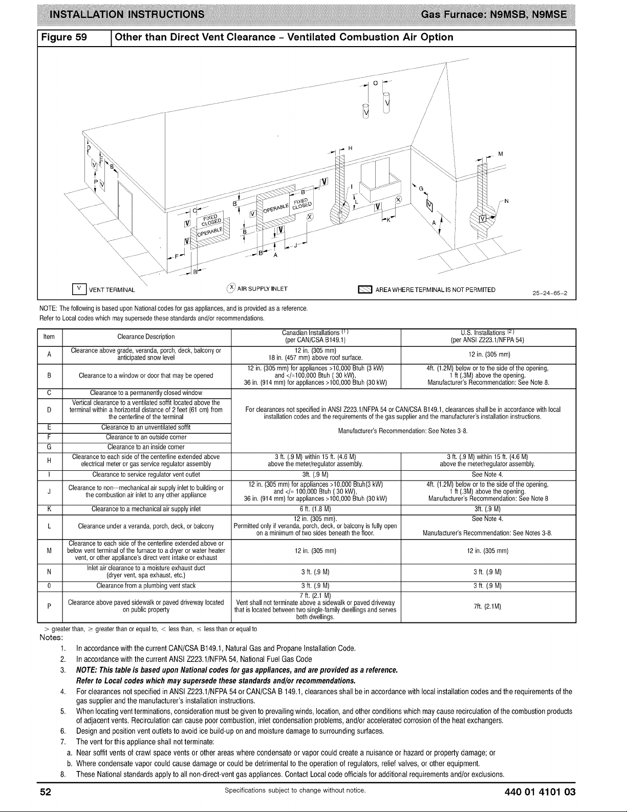
Figure 59 1Other than Direct Vent Clearance - Ventilated Combustion Air Option
D VENT TERMINAL qXi AIR SUPPLY INLET E_ AREA WHERE TERMINAL IS NOT PERMITED 25-24-55-2
NOTE:The followingis based uponNationalcodesfor gas appliances, and is providedas areference.
Refer to Local codeswhichmay supersedethese standardsand/orrecommendations.
Item
Clearanceabove grade, veranda,porch,deck,balconyor
A
B
C
D
E
F
G
H
J
K
L
M below ventterminal of the furnaceto adryer or water heater 12in. (305 ram) 12in. (305 ram)
N (dryervent, spaexhaust,etc.) 3 ft. (.9 M) 3 ft. (.9 M)
0 Clearancefrom a plumbingvent stack 3 ft. (.9 M) 3 ft. (.9 M)
p Clearanceabovepavedsidewalk orpaved drivewaylocated Ventshall notterminateabove asidewalk or paveddriveway
> greaterthan,> greaterthanorequalto, < lessthan,< lessthanorequalto
Notes:
Clearanceto awindow or doorthat maybe opened 1ft (.3M) abovethe opening.
Verticalclearanceto aventilated soffit locatedabovethe
terminal withina horizontaldistanceof 2feet (61 cm) from
Clearanceto eachside ofthe centerlineextended above
I
electricalmeteror gas serviceregulatorassembly
Clearanceto non mechanicalair supplyinlettobuilding or
the combustionair inlet to any otherappliance
Clearanceunder a veranda,porch, deck,or balcony Permittedonly if veranda, porch, deck,or balcony isfully open
Clearanceto eachside of the centedineextendedabove or
vent,or other appliance'sdirect vent intake or exhaust
1.
In accordancewith thecurrentCAN/CSAB149.1,NaturalGas andPropaneInstallationCode.
2.
In accordancewith thecurrentANSI Z223.1/NFPA54,NationalFuel GasCode
3.
NOTE:Thistable is basedupon Nationalcodesforgas appliances,andare providedasa reference.
ClearanceDescription
anticipatedsnowlevel 12 in. (305 ram)
12 in. (305ram)for appliances>10,000Btuh (3 kW)
36 in. (914ram)for appliances>100,000Btuh(30 kW)
Clearanceto apermanentlyclosedwindow
thecentedine ofthe terminal
Clearanceto an unventilatedsoffit
Clearanceto an outsidecorner
Clearanceto an insidecorner
Clearanceto serviceregulatorvent outlet
Clearanceto a mechanicalair supplyinlet
Inletair clearance toa moisture exhaust duct
on publicproperty that is locatedbetweentwo single-familydwellingsand serves 7ft. (2.1M)
Forclearancesnot specifiedinANSI Z223.1/NFPA54or CAN/CSAB149.1,clearances shallbe in accordancewith local
12 in. (305ram)for appliances>10,000Btuh(3 kW) 4ft. (1.2M)below or to the side ofthe opening,
36 in. (914ram)for appliances>100,000Btuh(30 kW) Manufacturer'sRecommendation:SeeNote 8
CanadianInstallations(1
(per CAN/CSAB149.1)
12in. (305ram)
18 in. (457ram)above roofsurface.
and</=100,000Btuh (30 kW),
installationcodesand the requirements of the gas supplierandthe manufacturer'sinstallationinstructions.
Manufacturer'sRecommendation:SeeNotes3-8.
3 ft. (.9 M) within15 ft. (4.6 M) 3ft. (.9 M)within15ft. (4.6 M)
abovethe meter/regulatorassembly, abovethe meter/regulatorassembly.
3ft. (.9 M) See Note4.
and</= 100,000 Btuh (30 kW), 1ft (.3M)abovethe opening.
6 ft. (1.8 M) 3ft. (.9 M)
12in. (305ram). See Note4.
on a minimumof two sides beneath thefloor. Manufacturer'sRecommendation:See Notes 3-8.
7 ft. (2.1 M)
bothdwellings.
4ft. (1.2M)below or tothe side ofthe opening,
Manufacturer'sRecommendation:SeeNote 8.
U.S. Installationst2}
(perANSI Z223.1/NFPA54)
Referto Loca/ codeswhich maysupersedethese standardsand/orrecommendations.
4. ForclearancesnotspecifiedinANSIZ223.1/NFPA54 or CAN/CSAB 149.1,clearancesshallbein accordancewithlocalinstallationcodesand therequirementsofthe
gas supplierandthe manufacturer'sinstallationinstructions.
5. Whenlocatingventterminations,considerationmustbegivento prevailingwinds,location,andotherconditionswhich maycauserecirculationof the combustionproducts
of adjacentvents.Recirculationcancause poorcombustion,inlet condensationproblems,and/or acceleratedcorrosionof theheat exchangers.
6. Designandpositionvent outletsto avoidicebuild-upon and moisturedamageto surroundingsurfaces.
7. Thevent forthis applianceshall notterminate:
a. Nearsoffitvents of crawlspace ventsor otherareaswherecondensateor vapor could createa nuisanceor hazardor propertydamage;or
b. Where condensatevapor couldcausedamageor could be detrimentalto the operationof regulators,reliefvalves, or other equipment.
8. These Nationalstandardsapplyto all non-direct-ventgasappliances.ContactLocalcodeofficialsfor additionalrequirementsand!orexclusions.
52 Specificationssubjectto change without notice. 440 O1 41O1 03
Page 53
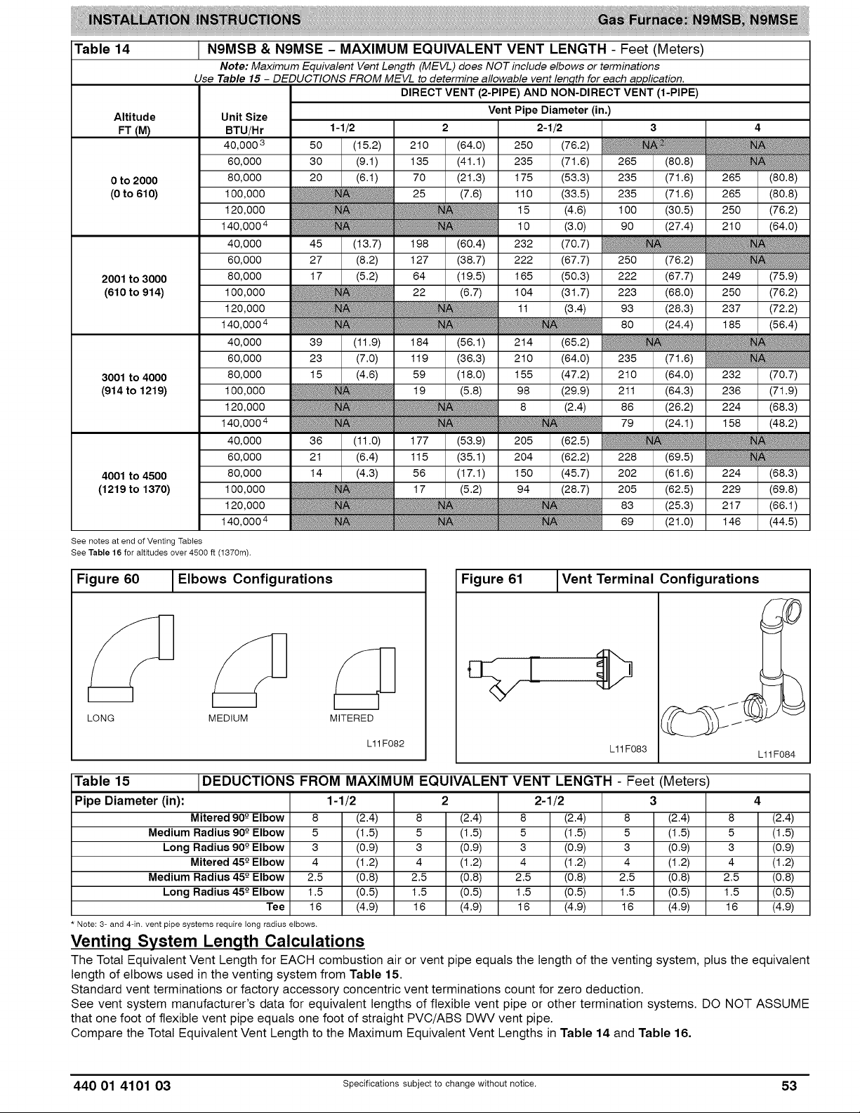
Table 14
Altitude
FT (M)
0 to 2000 80,000 (21.3) 175 235 (71.6) 265 (80.8)
(0 to 610) 100,000 25 (7.6) 110 235 (71.6) 265 (80.8)
2001 to 3000 80,000 64 (19.5) 165 222 (67.7) 249 (75.9)
(610 to 914) 100,000 22 (6.7) 104 223 (68.0) 250 (76.2)
3001 to 4000 80,000 59 (18.0) 155 (47.2) 210 (64.0) 232 (70.7)
(914 to 1219) 100,000 19 (5.8) 98 (29.9) 211 (64.3) 236 (71.9)
4001 to 4500 80,000 56 (17.1) 150 (45.7) 202 (61.6) 224 (68.3)
(1219 to 1370) 100,000 17 (5.2) 94 (28.7) 205 (62.5) 229 (69.8)
See notes at end of Venting Tables
See Table 16 for altitudes over 4500 ft (1370m).
N9MSB & N9MSE - MAXIMUM EQUIVALENT VENT LENGTH - Feet (Meters)
Note: Maximum Equivalent Vent Length (MEVL) does NOT include elbows or terminations
Use Table 15 - DEDUCTIONS FROM MEVL to determine allowable vent len,qth for each application.
Unit Size Vent Pipe Diameter (in,)
BTU/Hr
40,000 3 50 (64.0) 250
60,000 I 30 (41.1) 235 265 (80.8)
120,000 15 100 (30.5) 250 (76.2)
140,0004 10 90 (27.4) 210 (64.0)
40,000 I 45 (13.7) I 198 (60.4) 232
60,000 I 27 (8.2) 1127 (38.7) 222 250 (76.2)
120,000 1t 93 (28.3) 237 (72.2)
140,0004 80 (24.4) 185 (56.4)
40,000 I 39 (11.9) I 184 (56.1) 214 (65.2)
60,000 I 23 (7.0) 1 119 (36.3) 210 (64.0) 235 (71.6)
120,000 8 (2.4) 86 (26.2) 224 (68.3)
140,0004 79 (24.1) 158 (48.2)
40,000 I 36 (11.0) I 177 (53.9) 205 (62.5)
60,000 I 21 (8.4) 1 115 (35.1) 204 (62.2) 228 (69.5)
120,000 83 (25.3) 217 (66.1)
140,0004 69 (21.0) 146 (44.5)
1-1/2
(15.2) 210
(9.1) 1135
DIRECT VENT (2-PIPE) AND NON-DIRECT VENT (1-PIPE)
2 2-1/2 3 4
(76.2)
(71.6)
70
(53.3)
(33.5)
(4.6)
(3.0)
(70.7)
(67.7)
(50.3)
(31.7)
(3.4)
Figure 60 _Elbows Configurations
MEDIUM MITEREDLONG
Table 15
Pipe Diameter (in):
Medium Radius 90-0Elbow
Medium Radius 45 -0Elbow 2.5
* Note: 3- and 4-in. vent pipe systems require long radius elbows,
DEDUCTIONS FROM MAXIMUM EQUIVALENT VENT LENGTH - Feet (Meters)
Mitered 90-0Elbow
Long Radius 90-0Elbow
Mitered 45-0Elbow
Long Radius 45-0Elbow 1.5
Tee 16
L11F082
1-1/2 2 2-1/2 3 4
8 (2.4) 8 (2.4) 8 (2.4) 8 (2.4) 8 (2.4)
5 (1.5) 5 (1.5) 5 (1.5) 5 (1.5) 5 (1.5)
3 (0.9) 3 (0.9) 3 (0.9) 3 (0.9) 3 (0.9)
4 (1.2) 4 (1.2) 4 (1.2) 4 (1.2) 4 (1.2)
(0.8) 2.5 (0.8) 2.5 (0.8) 2.5 (0.8) 2.5 (0.8)
(0.5) 1.5 (0.5) 1.5 (0.5) 1.5 (0.5) 1.5 (0.5)
(4.9) 16 (4.9) 16 (4.9) 16 (4.9) 16 (4.9)
Figure 61 Vent Terminal Configurations
L11F083
L11F084
Venting System Length Calculations
The Total Equivalent Vent Length for EACH combustion air or vent pipe equals the length of the venting system, plus the equivalent
length of elbows used in the venting system from Table 15.
Standard vent terminations or factory accessory concentric vent terminations count for zero deduction.
See vent system manufacturer's data for equivalent lengths of flexible vent pipe or other termination systems. DO NOT ASSUME
that one foot of flexible vent pipe equals one foot of straight PVC/ABS DWV vent pipe.
Compare the Total Equivalent Vent Length to the Maximum Equivalent Vent Lengths in Table 14 and Table 16.
440 01 4101 03 Specifications subject to change without notice. 53
Page 54

Example 1
A direct-vent 60,000 BTUH furnace installed at 2100 ft. (640M). Venting system includes FOR EACH PIPE 100 feet (30 M) of vent
pipe, 95 feet (28 M) of combustion air inlet pipe, (3) 90°-long-radius elbows, (2) 450-long-radius elbows, and a factory accessory
concentric vent kit.
Can this application use 2-in. (50 mm ND) PVC/ABS DWV vent piping?
Measure the required linear length of air inlet
and vent pipe; insert the longest of the two here
Add equiv length of (3) 900-long-radius elbows
(use the highest number of elbows for either the 3 x (0.9 M)
vent or inlet pipe)
Add equiv length of (2) 450-long-radius elbows
(use the highest number of elbows for either the 2 x (0.5 M)
vent or inlet pipe)
Add equiv length of factory concentric vent term
Add correction for flexible vent pipe, if any
Total Equivalent Vent Length (TEVL)
3ff
1.5ft
lOOft
(30 M)
9ft.
(2.7 M)
3ft
(0.9 M)
Oft.
Oft.
112 ft.
(34 M)
Use length of the longer of the vent
or air inlet piping system
From Table 15
From Table 15
From Table 15
From Vent Manufacturer's
instructions; zero for PVC/ABS DWV
Add all of the above lines
Maximum Equivalent Vent Length (MEVL)
Is TEVL less than MEVL?
127 ft.
(38.7 M)
YES
For 2" pipe from Table 14
Therefore, 2" pipe MAY be used
Example 2
A direct-vent 60,000 BTUH furnace installed at 2100 ft. (640M). Venting system includes FOR EACH PIPE 100 feet (30 M) of vent
pipe, 95 feet (28 M) of combustion air inlet pipe, (3) 900-long-radius elbows, and a polypropylene concentric vent kit. Also includes 20
feet (6.1 M) of flexible polypropylene vent pipe, included within the 100 feet (30 M) of vent pipe.
Assume that one meter of flexible 60mm or 80mm polypropylene pipe equals 1.8 meters of PVC/ABS pipe. VERIFY FROM VENT
MANUFACTURER'S INSTRUCTIONS.
Can this application use 60mm (o.d.) polypropylene vent piping? If not, what size piping can be used?
Measure the required linear length of air inlet and
vent pipe; insert the longest of the two here
Add equiv length of (3) 900-long-radius elbows 3 ft
(use the highest number of elbows for either the 3 x (0.9 =
vent or inlet pipe) M) (2.7 M)
Add equiv length of (2) 450-long-radius elbows 0 ft.
(use the highest number of elbows for either the 0 x = (0 M)
vent or inlet pipe)
Add equiv length of factory concentric vent term x =
Add correction for flexible vent pipe, if any 8 x (6.1 =
Total Equivalent Vent Length (TEVL)
9 3.3 ft/ 3Oft.
M M (9 M)
1. 36 ft.
20ft
M) (11 M)
100 ft Use length of the longer of the vent
(30 M) or air inlet piping system
9ft.
175 ft
(53 U).
From Vent Manufacturer's instructions
From Vent Manufacturer's instructions
From Vent Manufacturer's instructions
From Vent Manufacturer's instructions
Add all of the above lines
127 ft.
Maximum Equivalent Vent Length (MEVL)
(38.7
For 2" pipe from Table 14
M)
Is TEVL less than MEVL?
Maximum Equivalent Vent Length (MEVL)
NO
250 ft.
(76.2
Therefore, 60ram pipe may NOT be
used; try 80ram
For 3" pipe from Table 14
M)
Is TEVL less than MEVL?
54 specificationssubjectto change without notice. 440 01 4101 03
YES
Therefore, 80ram pipe MAY be used
Page 55

Table 16
Altitude Unit Size
FT (M) BTU/Hr
4501 to 5000 80,000
(1370 to 1524) 100,000
5001 to 6000 80,000
(1524 to 1829) 100,000
6001 to 7000 80,000
(1829 to 2134) 100,000
7001 to 8000 80,000
(2134 to 2438) 100,000
8001 to 9000 80,000
(2438 to 2743) 100,000
9001 to 10,000 80,000
(2743 to 3048) 100,000
* Not all families have these models
NOTES:
N9MSB & N9MSE - MAXIMUM EQUIVALENT VENT LENGTH - Feet (Meters)
Note: Maximum Equivalent Vent Length (MEVL) does NOT include elbows or terminations.
Use DEDUCTIONS FROM MEVL - Table 15 to determine allowable vent length for each application.
Note: Vent sizing for Canadian installations over 4500 ft. (1370 M) above sea level are subject to acceptance
40,000
60,000
120,000
140,0004
40,000
60,000
120,000
140,0004
40,000
60,000
120,000
140,0004
40,000
60,000
120,000
140,0004
40,000
60,000
I 20 (6.1) I 111 I (33.8) I 198 (60.4) 221 (67.4)
I 27 (8.2) I 158 I (48.2) I 179 (54.6)
I 16 (4.9) I 103 I (31.4) I 186 (56.7) 207 (63.1)
I 21 (6.4) I 145 I (44.2) I 162 (49.4)
I 13 (4.0) I 96 I (29.3) I 174 (53.0) 194 (59.1)
I 15 (4.6) I 133 I (40.5) I 146 (44.5)
I 10 (3.0) I 89 I (27.1) I 163 (49.7) 181 (55.2)
I 10 (3.0) I 121 I (36.9) I 130 (39.6)
I 7 (2.1) I 82 1(25.o) 1 152 (46.3) 168 (51.2)
by the local authorities havin,q jurisdiction.
DIRECT VENT (2-PIPE) AND NON-DIRECT VENT (1-PIPE)
Vent Pipe Diameter
1-1/2 2 2-1/2 3
33 1(10.1) 171 1(52.1) 196 (59.7)
54 (16.5) 146 (44.5) 195 (59.4)
16 (4.9) 91 (27.7) 200 (61.0)
80 (24.4)
60 (18.3)
49 (14.9) 137 (41.8) 183 (55.8)
12 (3.7) 85 (25.9) 188 (57.3)
74 (22.6)
50 (15.2)
44 1(13.4) 1 120 (36.6) 171 (52.1)
10 (3.0) I 79 (24.1) 178 (54.3)
68 (20.7)
41 (12.5)
40 1(12.2) 1 120 (36.6) 159 (48.5)
73 (22.3) 167 (50.9)
62 (18.9)
32 (9.8)
35 1(10.7) 1 111 (33.8) 148 (45.1)
120,000
140,0004
40,000
60,000
120,000
140,0004
I 5 (1.5) I 110 I (33.5) I 115 (35.1)
76 I (23.2) I 142 (43.3) 156 (47.5)
31 (9.4) I 103 (31.4) 137 (41.8)
67 (20.4) 157 (47.9)
56 (17.1)
23 (7.0)
62 (18.9) 147 (44.8)
51 (15.5)
16 (4.9)
216 (65.8)
222 (67.7)
211 (64.3)
134 (40.8)
200 (61.0)
208 (63.4)
199 (60.7)
109 (33.2)
185 (56.4)
195 (59.4)
187 (57.0)
87 (26.5)
170 (51.8)
182 (55.5)
175 (53.3)
63 (19.2)
156 (47.5)
170 (51.8)
164 (50.0)
42 (12.8)
142 (43.3)
157 (47.9)
153 (46.6)
20 (6.1)
1. Use only the vent pipe sizes shown for each furnace. It is NOT necessary to choose the smallest diameter pipe possible for
venting.
2. NA = Not allowed. Pressure switch will not close, or flame disturbance may result.
3. Total equivalent vent lengths under 10 ft. for 40k BTUH furnaces from 0 to 2000 ft (0 to 610m) above sea level require use of
an inducer outlet choke. Failure to use an outlet choke may result in flame disturbance or flame sense lock-out.
4. Not all furnace families include 140,000 BTUH input models.
5. Vent sizing for Canadian installation over 4500 ft. (1370 m) above sea level are subject to acceptance by local authorities having
jurisdiction.
6. Size both the combustion air and vent pipe independently, then use the larger size for both pipes.
7. Assume two 45° degree elbows equal one 90° degree elbow. Wide radius elbows are desirable and may be required in some
cases.
8. Elbow and pipe sections within the furnace casing and at the vent termination should not be included in vent length or elbow
count.
9. The minimum pipe length is 5 (1.5) linear feet (meters) for all applications.
10. Use 3-in (76 mm) diameter vent termination kit for installations requiring a 4-in (102 mm) diameter pipe.
440 01 4101 03 Specifications subject to change without notice. 55
Page 56
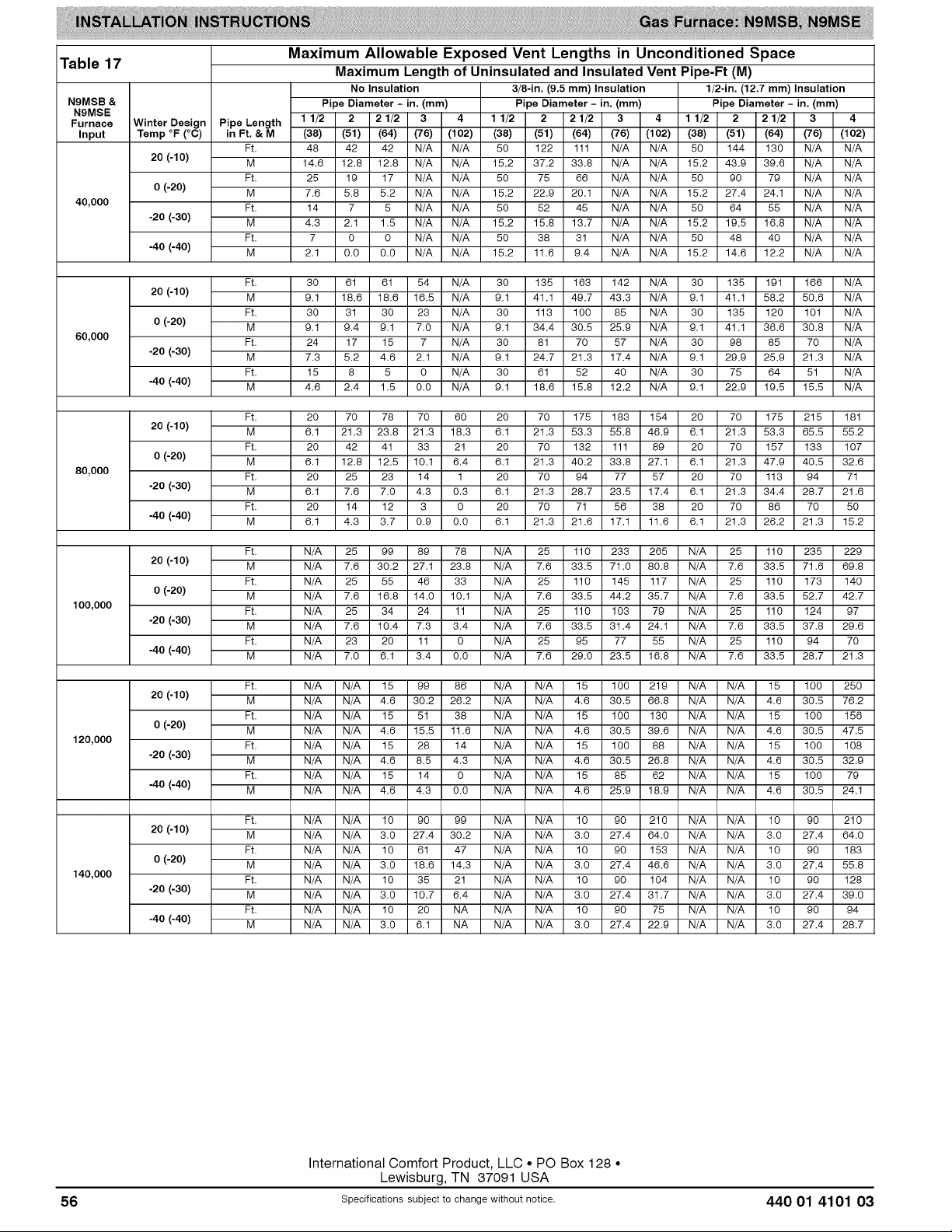
Maximum Allowable Exposed Vent Lengths in Unconditioned Space
Table 17 Maximum Length of Uninsulated and Insulated Vent Pipe-Ft (M)
N9MSB &
N9MSE
Furnace
Input
40,000
Winter Design
Temp °F (°C)
20 (-10)
0(-20)
-20(-30)
-40(-40)
Pipe Length
in Ft.& M
Ft
M
Ft
M
Ft
M
Ft
M
No Insulation
Pipe Diameter - in. (mm)
1 1/2 2 2 1/2 3 4
(38) (51) (64) (76) (102)
48 42 42 N/A N/A
14.6 12.8 12.8 N/A N/A
25 19 17 N/A N/A
7.6 5.8 5.2 N/A N/A
14 7 5 N/A N/A
4.3 2.1 1.5 N/A N/A
7 0 0 N/A N/A
2.1 0.O 0.O N/A N/A
3/8-in. (9.5 mm) Insulation
Pipe Diameter - in. (mm)
1 1/2 2 2 1/2 3 4
(38) (51) (64) (76) (102)
50 122 111 N/A N/A
15.2 37.2 33.8 N/A N/A
50 75 66 N/A N/A
15.2 22.9 20.1 N/A N/A
50 52 45 N/A N/A
15.2 15.8 13.7 N/A N/A
50 38 31 N/A N/A
15.2 11.6 9.4 N/A N/A
1/2-in. (12.7 mm) Insulation
Pipe Diameter - in. (mm)
1 1/2 2 2 1/2 3 4
(38) (51) (64) (76) (102)
50 144 130 N/A N/A
15.2 43.9 39.6 N/A N/A
50 90 79 N/A N/A
15.2 27.4 24.1 N/A N/A
50 64 55 N/A N/A
15.2 19.5 16.8 N/A N/A
50 48 40 N/A N/A
15.2 14.6 12.2 N/A N/A
20 (-10) M 9.1 18.6 18.6 16.5 N/A 9.1 41.1 49.7 43.3 N/A 9.1 41.1 58.2 50.6 N/A
0 (-20) M 9.1 9.4 9.1 7.0 N/A 9.1 34.4 30.5 25.9 N/A 9.1 41.1 36.6 30.8 N/A
60,000 Ft. 24 17 15 7 N/A 30 81 70 57 N/A 30 98 85 70 N/A
-20 (-30) M 7.3 5.2 4.6 2.1 N/A 9.1 24.7 21.3 17.4 N/A 9.1 29.9 25.9 21.3 N/A
-40 (-40) M 4.6 2.4 1.5 0.O N/A 9.1 18.6 15.8 12.2 N/A 9.1 22.9 19.5 15.5 N/A
20 (-10) M 6.1 21.3 23.8 21.3 18.3 6.1 21.3 53.3 55.8 46.9 6.1 21.3 53.3 65.5 55.2
0 (-20) M 6.1 12.8 12.5 10.1 6.4 6.1 21.3 40.2 33.8 27.1 6.1 21.3 47.9 40.5 32.6
80,000 Ft. 20 25 23 14 1 20 70 94 77 57 20 70 113 94 71
-20 (-30) M 6.1 7.6 7.0 4.3 0.3 6.1 21.3 28.7 23.5 17.4 6.1 21.3 34.4 28.7 21.6
-40 (-40) M 6.1 4.3 3.7 0.9 0.O 6.1 21.3 21.6 17.1 11.6 6.1 21.3 26.2 21.3 15.2
20 (-10) M N/A 7.6 30.2 27.1 23.8 N/A 7.6 33.5 71.O 80.8 N/A 7.6 33.5 71.6 69.8
0 (-20) M N/A 7.6 16.8 14.0 10.1 N/A 7.6 33.5 44.2 35.7 N/A 7.6 33.5 52.7 42.7
100,000 Ft. N/A 25 34 24 11 N/A 25 110 103 79 N/A 25 110 124 97
-20 (-30) M N/A 7.6 10.4 7.3 3.4 N/A 7.6 33.5 31.4 24.1 N/A 7.6 33.5 37.8 29.6
-40 (-40) M N/A 7.0 6.1 3.4 0.O N/A 7.6 29.0 23.5 16.8 N/A 7.6 33.5 28.7 21.3
20 (-10) M N/A N/A 4.6 30.2 26.2 N/A N/A 4.6 30.5 66.8 N/A N/A 4.6 30.5 76.2
0 (-20) M N/A N/A 4.6 15.5 11.6 N/A N/A 4.6 30.5 39.6 N/A N/A 4.6 30.5 47.5
120,000 Ft. N/A N/A 15 28 14 N/A N/A 15 100 88 N/A N/A 15 100 108
-20 (-30) M N/A N/A 4.6 8.5 4.3 N/A N/A 4.6 30.5 26.8 N/A N/A 4.6 30.5 32.9
-40 (-40) M N/A N/A 4.6 4.3 0.O N/A N/A 4.6 25.9 18.9 N/A N/A 4.6 30.5 24.1
Ft. 30 61 61 54 N/A 30 135 163 142 N/A 30 135 191 166 N/A
Ft. 30 31 30 23 N/A 30 113 10O 85 N/A 30 135 120 101 N/A
Ft. 15 8 5 0 N/A 30 61 52 40 N/A 30 75 64 51 N/A
Ft. 20 70 78 70 60 20 70 175 183 154 20 70 175 215 181
Ft. 20 42 41 33 21 20 70 132 111 89 20 70 157 133 107
Ft. 20 14 12 3 0 20 70 71 56 38 20 70 86 70 50
Ft. N/A 25 99 89 78 N/A 25 110 233 265 N/A 25 110 235 229
Ft. N/A 25 55 46 33 N/A 25 110 145 117 N/A 25 110 173 140
Ft. N/A 23 20 11 0 N/A 25 95 77 55 N/A 25 110 94 70
Ft. N/A N/A 15 99 86 N/A N/A 15 10O 219 N/A N/A 15 10O 250
Ft. N/A N/A 15 51 38 N/A N/A 15 100 130 N/A N/A 15 100 156
Ft. N/A N/A 15 14 0 N/A N/A 15 85 62 N/A N/A 15 10O 79
20 (-10) M N/A N/A 3.0 27.4 30.2 N/A N/A 3.0 27.4 64.0 N/A N/A 3.0 27.4 64.0
0 (-20) M N/A N/A 3.0 18.6 14.3 N/A N/A 3.0 27.4 46.6 N/A N/A 3.0 27.4 55.8
140,000 Ft. N/A N/A 10 35 21 N/A N/A 10 90 104 N/A N/A 10 90 128
-20 (-30) M N/A N/A 3.0 10.7 6.4 N/A N/A 3.0 27.4 31.7 N/A N/A 3.0 27.4 39.0
-40 (-40) M N/A N/A 3.0 6.1 NA N/A N/A 3.0 27.4 22.9 N/A N/A 3.0 27.4 28.7
Ft. N/A N/A 10 90 99 N/A N/A 10 90 21 O N/A N/A 10 90 21 O
Ft. N/A N/A 10 61 47 N/A N/A 10 90 153 N/A N/A 10 90 183
Ft. N/A N/A 10 20 NA N/A N/A 10 90 75 N/A N/A 10 90 94
International Comfort Product, LLC • PO Box 128 •
Lewisburg, TN 37091 USA
56 Specificationssubjectto change without notice. 440 01 4101 03
 Loading...