

ICP N9MP1100F14A, N9MP1050A12A, N9MP1100J20A, N9MP1125J20A, N9MP2050A12A Installation Instructions Manual
...Page 1
N9MP2
Four Position Condensing Gas Furnace
SAFETY REQUIREMENTS
Recognize safety information. This is the safety-alert symbol/X X. When you see this symbol on the furnace and in instructions or
manuals be alert to the potential for personal injury.
Understand the signal words DANGER, WARNING, or CAUTION. These words are used with the safety-alert symbol. DANGER
identifies the most serious hazards, those that will result in severe personal injury or death. WARNING signifies a hazard that could
result in personal injury or death. CAUTION is used to identify unsafe practices that could result inminor personal injury or product and
property damage.
Installing and servicing heating equipment can be hazardous due to gas and electrical components. Only trained and qualified person-
nel should install, repair, or service heating equipment.
Untrained service personnel can perform basic maintenance functions such as cleaning and replacing air filters. All other operations
must be performed by trained service personnel. When working on heating equipment, observe precautions in the literature, on tags,
and on labels attached to or shipped with the unit and other safety precautions that may apply.
Follow all safety codes. In the United States, follow all safety codes including the current edition National Fuel Gas Code (N FGC) NFPA
No. 54/ANSIZ223.1. In Canada, refer to the current edition of the National Standard Canada CAN/CGA-B149.1 - and .2-M91 Natural
Gas and Propane Installation Codes (NSCNGPIC). Wear safety glasses and work gloves. Have fire extinguisher available during start-
up and adjustment procedures and service calls.
These instructions cover minimum requirements and conform to existing national standards and safety codes. In some instances,
these instructions exceed certain local codes and ordinances, especially those that may not have kept up with changing residential
construction practices. We requre these instructions as a minimum for a safe installation.
Manufactured by:
International Comfort Products Corporation (USA)
Lewieburg, TN USA 87091
Table of Contents
1.SafeInstallationRequirements................. 4
2.Installation................................ 5
3.Combustion&VentilationAir .................. 8
4.Vent& CombustionAirPiping ................ 10
5.GasSupplyandPiping ...................... 24
6.ElectricalWiring ........................... 28
7.DuctworkandFilter(Upflow/Horizontal)......... 29
8. ChecksandAdjustments.................... 33
9.FurnaceMaintenance ....................... 35
10.SequenceofOperation&Diagnostics.......... 35
11.ConcentricVentTermination................. 40
Fire or Explosion hazard.
This furnace is not designed for use in mobile
homes, trailers or recreational vehicles.
Such use could result in death, bodily injury
and/or property damage.
Printed in U.S.A. LP1 9/4/2001 440 01 1010 04
Page 2
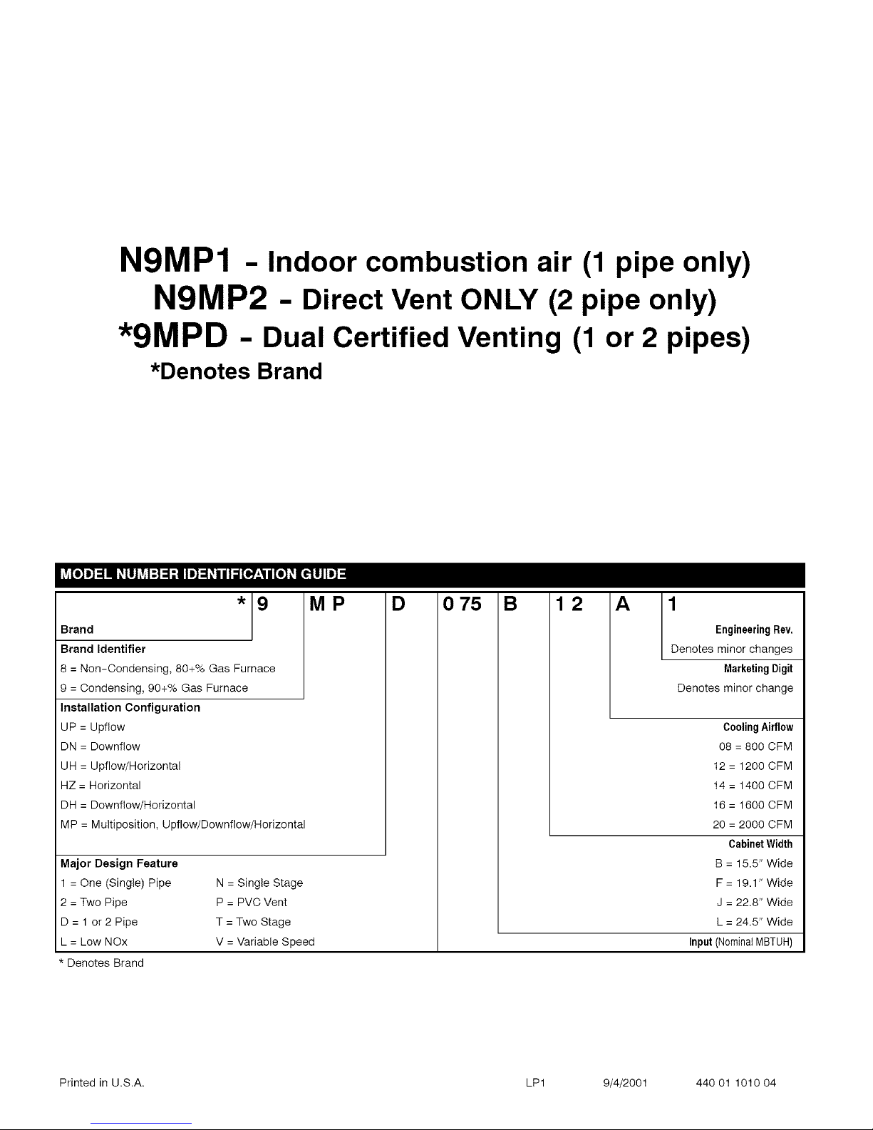
N9MP1 - Indoor combustion air (1 pipe only)
N9MP2 - Direct Vent ONLY (2 pipe only)
*9MPD - Dual Certified Venting (1 or 2 pipes)
*Denotes Brand
*9
Brand
Brand Identifier
8 = Non-Condensing, 80+% Gas Furnace
9 = Condensing, 90+% Gas Furnace
Installation Configuration
UP = Upflow
DN = Downfiow
UH = Upflow/Horizontal
HZ = Horizontal
DH = Downfiow/Horizontal
MP = Multiposition, Upflow/Downflow/Horizontal
Major Design Feature
= One (Single) Pipe
2 = Two Pipe
D=I or2Pipe
L = Low NOx
* Denotes Brand
N = Single Stage
P = PVC Vent
T = Two Stage
V = Variable Speed
MP D 0 75 B 12 A
/
1
Engineering Rev.
L
Denotes minor changes
MarketingDigit
Denotes minor change
Cooling Airflow
08 = 800 CFM
12 = 1200 CFM
14 = 1400 CFM
16 = 1600 CFM
20 = 2000 CFM
Cabinet Width
B = 15.5" Wide
F = 19.1" Wide
J = 22.8" Wide
L = 24.5" Wide
Input (NominalMBTUH)
Printed in U.S.A. LP1 9/4/2001 440 01 1010 04
Page 3
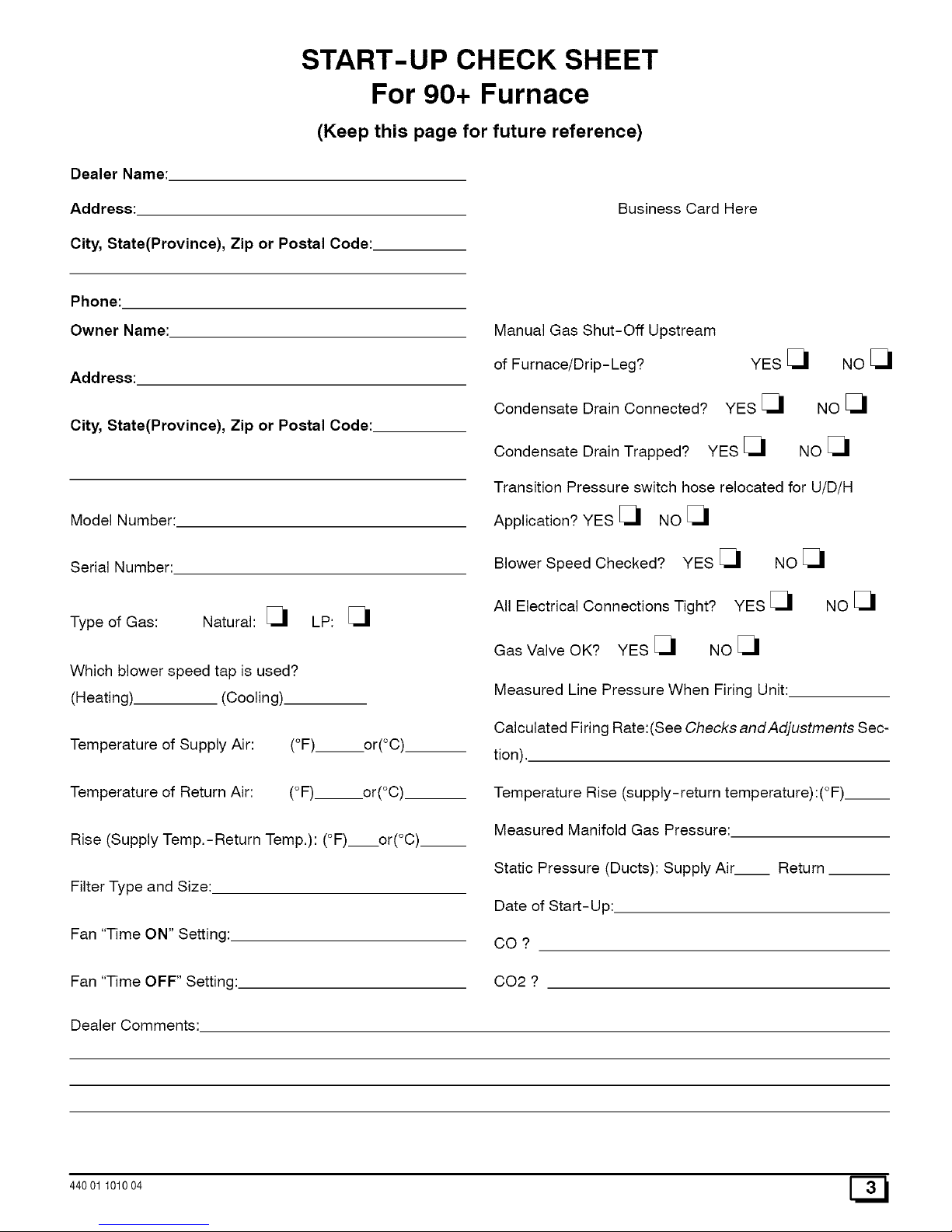
START-UP CHECK SHEET
For 90+ Furnace
(Keep this page for future reference)
Dealer Name:
Address:
City, State(Province), Zip or Postal Code:
Business Card Here
Phone:
Owner Name:
Address:
City, State(Province), Zip or Postal Code:
Model Number:
Serial Number:
Type of Gas: Natural: [_
Which blower speed tap is used?
(Heating). (Cooling)
Temperature of Supply Air:
Temperature of Return Air:
LP: _1
(°F). or(°C).
(°F) or(°C)
Rise (Supply Temp,-Return Temp,): (°F) or(°C).__
Filter Type and Size:
Fan "Time ON" Setting:
Fan "Time OFF" Setting:
Manual Gas Shut-Off Upstream
of Furnace/Drip-Leg?
Condensate Drain Connected?
YES _1 NO _1
YES _1 NO _1
NO_1
Condensate Drain Trapped? YES [_
Transition Pressure switch hose relocated for U/D/H
Application? YES _ NO _
Blower Speed Checked? YES _1 NO _1
All Electrical Connections Tight? YES _1 NO _1
Gas Valve OK? YES _ NO _
Measured Line Pressure When Firing Unit:
Calculated Firing Rate:(See Checks andAdjustments Sec-
tion),.
Temperature Rise (supply-return temperature):(°F)__
Measured Manifold Gas Pressure:
Static Pressure (Ducts): Supply Air Return
Date of Start-Up:
CO ?
0O2 ?
Dealer Comments:
44001 101004
Page 4
1. Safe Installation Requirements
Installation or repairs made by unqualified
persons can result in hazards to you and others.
Installation MUST conform with local codes or, in
the absence of local codes, with codes of all
governmental authorities having jurisdiction.
The information contained in this manual is
intended for use by a qualified service technician
who is experienced in such work, who is familiar
with all precautions and safety procedures
required in such work and is equipped with the
proper tools and test instruments.
Failure to carefully read and follow all instruc-
tions in this manual can result in furnace
malfunction, death, personal injury and/or
property damage.
NOTE: This furnace is design certified by the Canadian Stan-
dards Association (CSA) for installation in the United States and
Canada. Refer to the appropriate codes, along with Figure 1 or
Figure 2 and this manual, for proper installation.
• This furnace is NOT approved for installation in
mobile homes, trailers or recreation vehicles,
• Do NOT use this furnace as a construction heater or to
heat a building that is under construction.
Use only the Type of gas approved for this furnace (see
Rating Plate on unit). Overfiring will result in failure of
heat exchanger and cause dangerous operation. (Fur-
naces can be converted to LR gas with approved kit.)
• Do NOT use open flame to test for gas leak.
heaters, furnaces, gas-fired fireplaces, wood fireplaces,
and several other items. Carbon monoxide can cause seri-
ous bodily injury and/or death. Therefore, to help alert
people of potentially dangerous carbon monoxide levels,
you should have carbon monoxide detectors listed by a na-
tionally recognized agency (e.g. Underwriters Laborato-
ries or International Approval Services) installed and
maintained in the building or dwelling (see Note below).
Carbon monoxide or "CO" is a colorless and odorless gas
produced when fuel is not burned completely or when the
flame does not receive sufficient oxygen.
B. There can be numerous sources of fire or smoke in a build-
ing or dwelling. Fire or smoke can cause serious bodily in-
jury, death, and/or property damage. Therefore, in order to
alert people of potentially dangerous fire or smoke, you
should have fire and smoke detectors listed by Underwrit-
ers Laboratories installed and maintained in the building or
dwelling (see Note below).
Note: The manufacturer of your furnace does not test any de-
tectors and makes no representations regarding any brand
or type of detector.
C. To ensure safe and efficient operation of your unit, you
should do the the following:
1. Thoroughly read this manual and labels on the unit.
This will help you understand how your unit operates and
the hazards involved with gas and electricity.
2. Do not use this unit if any part has been under water.
Immediately call a qualified service technician to inspect
the unit and to replace any part of the control system and
any gas control which has been under water.
3. Never obstruct the vent grilles, or any ducts that pro-
vide air to the unit. Air must be provided for proper com-
bustion and ventilation of flue gases.
FreezingTemperaturesand YourStructure
• Ensure adequate combustion and ventilation air is pro-
vided to the furnace.
• Seal around supply and return air ducts.
• The vent system MUST be checked to determine that it is
the correct type and size.
• Install correct filter type and size.
Freeze warning.
Turn off water system.
If your unit remains shut off during cold weather
the water pipes could freeze and burst, resulting
in serious water damage.
• Unit MUST be installed so electrical components are
protected from direct contact with water.
NOTE: It is the personal responsibility and obligation of the end
user to contact a qualified installer to ensure that the installation is
adequate and conforms to governing codes and ordinances.
Safety Rules
Your unit is built to provide many years of safe and dependable
service provided it is properly installed and maintained. However,
abuse and/or improper use can shorten the life of the unit and
create hazards for you, the owner.
A. The U.S. Consumer Product Safety Commission recom-
mends that users of gas- burning appliances install carbon
monoxide detectors. There can be various sources of car-
bon monoxide in a building or dwelling. The sources could
be gas-fired clothes dryers, gas cooking stoves, water
Your unit is equipped with safety devices that may keep it from op-
erating if sensors detect abnormal conditions such as clogged ex-
haust flues.
If your unit remains shut off during cold weather the water pipes
could freeze and burst, resulting in serious water damage.
Ifthe structure will be unattended during cold weather you should
take these precautions.
1. Turn off main supply water into the structure and drain the
water lines if possible. Open faucets in appropriate areas.
2. Have someone check the structure frequently during cold
weather to make sure it is warm enough to prevent pipes
from freezing. Suggest they call qualified service agency, if
required.
Winter Shutdown
If you go away during the winter months and do not leave the heat
on in your home, the plastic transition box and the condensate
44001 101004
Page 5

traponthefurnacemustbeprotectedfromfreezedamage.(See
Figure8troughFigure15)
1. Disconnectthe5/8"ODrubberhosefromtheventdrainfit-
tingthatislocateddownstreamofthecombustionblower.
Insertafunnelintothehoseandpourfour(4)ouncesof
sanitarytype(RV)antifreezeintothecondensatetrap.Re-
connectthe5/8"ODrubberhosetothestubonthevent
drainfitting.Securewiththehoseclamp.
2. Installation
2. Disconnect the 3/4" OD rubber hose from the condensate
trap. Insert a funnel into the hose and and pour four(4)
ounces of sanitary type (RV) antifreeze into the plastic
Transition box. Squeeze the hose together near the end
and quickly reconnect the 3/4" OD rubber hose to the stub
on the condensate trap. Secure with the hose clamp.
When you return home, your furnace will be ready to start, as it is
not necessary to drain the antifreeze from the furnace.
Poison carbon monoxide gas Hazard.
This furnace can NOT be common vented or
connected to any type B, BW or L vent or vent
connector, nor to any portion of a factory-built or
masonry chimney. If this furnace is replacing a
previously common-vented furnace, it may be
necessary to resize the existing vent and
chimney to prevent oversizing problems for the
other remaining appliance(s). See Venting and
Combustion Air Check in Gas Vent Installation
section. This furnace MUST be vented to the
outside.
Failure to properly vent this furnace or other
appliances can result in death, personal injury
and/or property damage.
LocationandClearances
Refer to Figure 1 or Figure 2 for typical installation and ba-
sic connecting parts required. Refer to Figure 4 for typical
horizontal direct vent installation and basic connecting
parts required. Supply and return air plenums and duct are
also required.
If furnace is a replacement, it is usually best to install the
furnace where the old one was. Choose the location or
evaluate the existing location based upon the minimum
clearance and furnace dimensions (Figure 3).
CAUTION
Special precautions MUST be made if installing
furnace in an area which may drop below freezing. This
can cause improper operation or damage to
equipment. Iffurnace environment has the potential of
freezing, the drain trap and drainline must be
protected. The use of electric heat tape or RV
antifreeze is recommended for these installations.
(See "Condensate Trap Freeze Protection Section")
Do NOT operate furnace in a corrosive atmosphere
containing chlorine, fluorine or any other damaging
chemicals. Refer to Combustion & Ventilation Air
section, Contaminated Combustion Air.
Typical Upflow Installation
AIuminumornon-rustingshietdrecommended.
(SeeVentTerminationShieldingfordimensions).
•8" Min. _ I_
20' Max. rq _ InletPipe Ooup%gonendsoi
in same <_ (_ _-_ (notusedon exhaustpipe.Total
atmospheric Single Pipe pipe& couplingout-
zone model) sidestructure= 8"
VentPipes MUSTbe
supported
Horizontallyand
Vertically
Min.
Max.
zone
* Increaseminimumfrom8" to 18" forcold climates (sustainedtemperatures
below0 oF). 25-23-33
Typical Downflow Installation
SeeVentTermination
ShieldinginVentSection.
I_ "8" Min.
Inlet Pipe _ _] 20' Max.
(notusedon_H in same
single pip-_(_ c_) atmospheric zone
model)
Vent PipesMUSTb
supportedHorizonta
andVertically
\_ _ "////_/////////Y////_
Couplingon inside
andoutsideofwait
torestrainventpipe
Min.
Max.
same
* Increaseminimumfrom8" to 18" for coldclimates(sustainedtemperatures
below0°F).
25-23-33a
44001 101004
Page 6
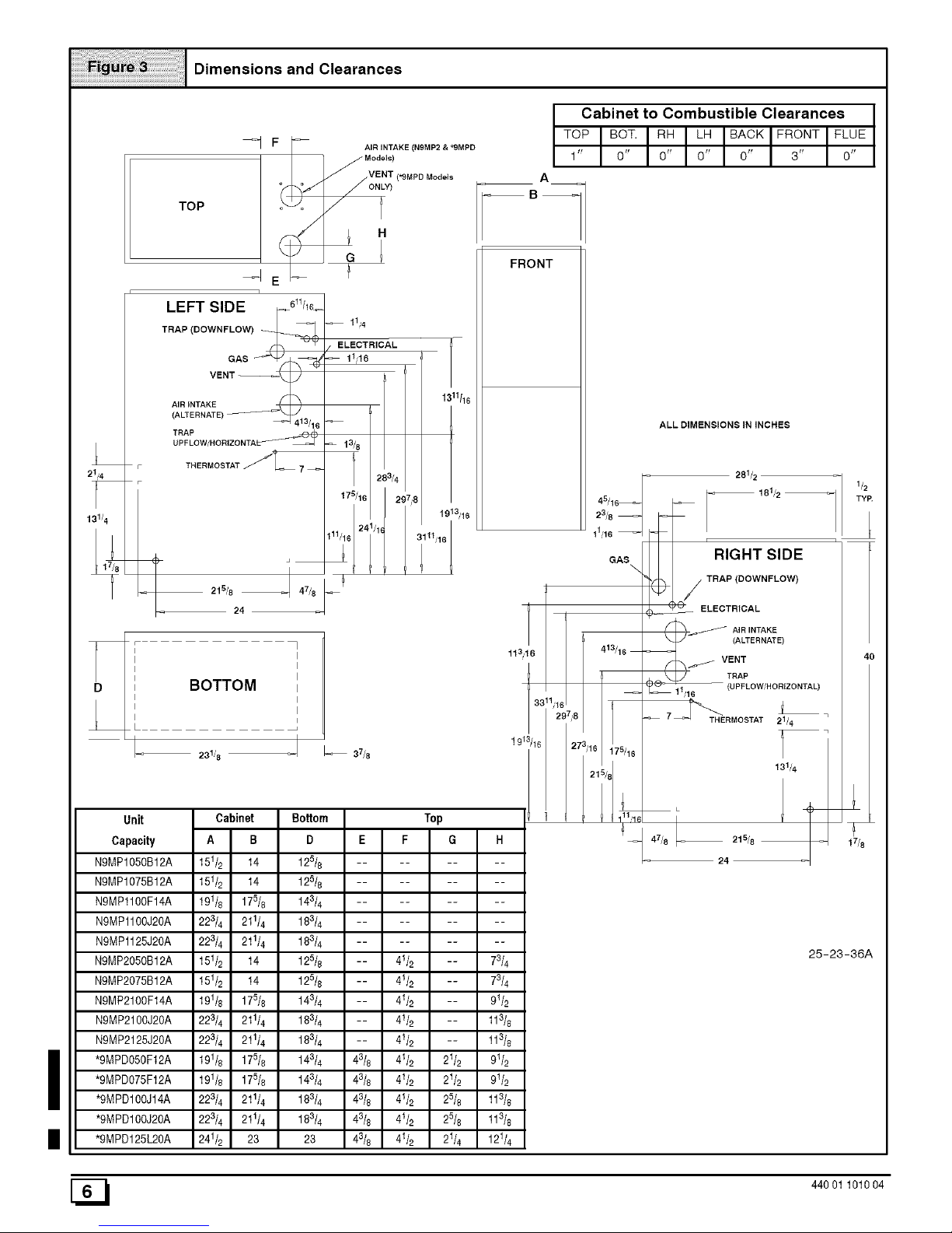
Dimensions and Clearances
TOP
_=1 F I_ AIRd'NT)ANE (N9M P2 & _9MPD
]
LEFT SIDE [_5"/_L
TRAP (DOWNFLOW) j_ _1 )
VEN GpS _
413/16
TRFALPoW/RORIZONTAL_ _
THERMOSTAT fT_ 7 _
215/8 1 47/8
24
11,,4
ELECTRICAL
11,,16
1 11/16
13£8 2 3/4
175/16 / 2_,7,'8
24 /1_
3111,,16
BOTTOM
Unit
Capacity
N9MP1050B12A
N9MP1075B12A
N9MP1100F14A
N9MP1100J20A
N9MP1125J20A
N9MP2050B12A
N9MP2075B12A
N9MP21OOF14A
NgMP2100J20A
NgMP2125J20A
*9MPD05OF12A
*9MPD075F12A
*gMPD100J14A
*gMPD100J20A
*9MPD125L2OA
Cabinet Bottom
D
125/8
125/8
143/4
183/4
183/4
125/8
125/8
143/4
183/4
183/4
143/4
143/4
183/4
183/4
23
A
B_
FRONT
113,,16
1913/16
Cabinet to Combustible Clearances
TOPBOT.R. FRONTFL E
1 0 0 0 0 3 0
ALL DIMENSIONS IN INCHES
GAS
\
281/2
181/2
r
RIGHT SIDE
TRAP (DOWNFLOW)
ELECTR)CAL
A]RINTAKE
(ALTERNATE)
VENT
TRAP
11,,16 (UPFLOW/HORIZONTAL)
L
THERMOSTAT 21/4
131/4
• (;
-- 215/8
24
25-23-36A
[_ 44001 101004
Page 7
InstallationRequirements
1. Install furnace level.
2. This furnace is NOT to be used for temporary heat of build-
ings or structures under construction.
3. Install furnace as centralized as practical with respect to the
heat distribution system.
4. Install the vent pipes as short as practical. (See Vent and
Combustion Air Piping section).
5. Maintain clearance for fire safety and servicing. A front
clearance of 30" is recommended for access to the burner,
controls and filter.
6. Use a raised base for upflow furnace if the floor is damp or
wet at times.
For downflow installations, non combustible subbase must
be used under the furnace unless installation is on a non
combustible floor surface. This requirement applies even
when a coi! box or cabinet is used.
Fire Hazard.
Place furnace on noncombustible subbase on
downflow applications, unless installing on
non-combustible flooring.
Failure to install unit on noncombustible
subbase can result in death, personal injury
and/or property damage.
9.
For horizontal installations, line contact is permissible only
between lines formed by intersection of back and two sides
of furnace jacket, and building joists, studs or framing.
Residential garage installations require:
Burners and ignition sources installed at least 18" above
the floor.
• Located or physically protected from possible damage
by a vehicle.
10. Local codes may require a drain pan under the entire fur-
nace and condensate trap when the furnace is installed in
attic application.
InstallationPositions
This furnace can be installed in an upflow, horizontal (either left or
right) or downflow airflow position. DO NOT install this furnace on
its back. For the upflow position, the return air ductwork can be
attached to either the left or right side panel and/or the bottom. For
horizontal and downflow positions, the return air ductwork must
be attached to the bottom. The return air ductwork must never be
attached to the back of the furnace.
FurnaceInstallationConsiderations
The installation of the furnace for a given application will dictate
the position of the furnace, the airflow, ductwork connections,
vent and combustion air piping. Consideration must be given to
the following:
CondensateTrap and Drain Lines
The supplied condensate trap must be attached to the furnace
side panel on either the left or right side. For horizontal installa-
tions, the drain trap is vertically attached to the side panel below
the furnace. A minimum clearance of 5" below the furnace is re-
44001 101004
quired for the condensate trap. Downward slope of the conden-
sate drain line from the condensate trap to the drain location must
be provided. Adequate freeze protection of the drain trap and the
drain line must be provided. See "Condensate Drain Trap"section
for further details.
Leveling
Proper leveling of the furnace must be provided to insure proper
drainage of the condensate from the furnace. The furnace must
be level to within 1/4" from front to back and from side to side for
upflow and downflow installations or top to bottom for horizontal
installations.
Vent and Combustion Air Connections
On the Dual Certified furnace, the vent and combustion air pipes
attach to the furnace through the top panel for the upflow and hori-
zontal installations. For the downflow installation, the vent and
combustion air pipes attach to the furnace through the alternate
locations on the furnace side panels.
Note: On the Direct Vent furnace, the vent pipe attaches to the fur-
nace through the side panels. The combustion air pipe attaches to
the top panel or to the alternate location on the side panel.
On the Single Pipe furnace, the vent pipe attaches to the furnace
through the furnace side panels.
Note: Repositioning of the combustion blower is required for the
vent pipe connection to the furnace through the "right side" panel.
See "Vent and Combustion Air Piping" section for further details.
HorizontalFurnaceInstallation
This furnace can be installed horizontally in an attic, basement,
crawl space, alcove, or suspended from a ceiling in a basement or
utility room. See Figure 4. Do not install furnace on its back or in
the reverse airflow positions as safety control operation will be ad-
versely affected.
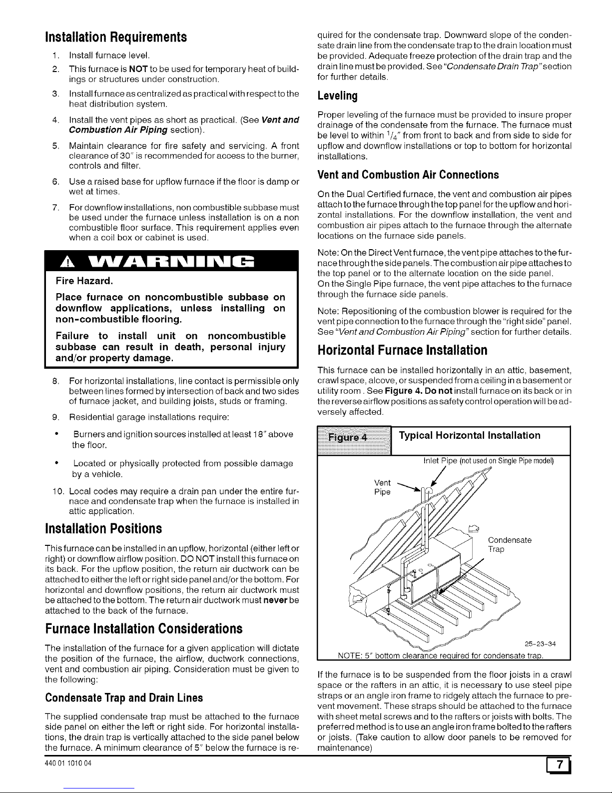
Typical Horizontal Installation
Inlet Pipe (notusedonSinglePipemodel)
Vent
Pipe
Condensate
Trap
25-23-34
NOTE: 5" bottom clearance required for condensate trap.
If the furnace is to be suspended from the floor joists in a crawl
space or the rafters in an attic, it is necessary to use steel pipe
straps or an angle iron frame to ridgely attach the furnace to pre-
vent movement. These straps should be attached to the furnace
with sheet metal screws and to the rafters or joists with bolts. The
preferred method isto use an angle iron frame bolted to the rafters
or joists. (Take caution to allow door panels to be removed for
maintenance)
Page 8
If the furnace is to be installed in a crawl space, consult local
codes. A suitable concrete pad or blocks are recommended for
crawl space installation on the ground.
NOTE: 5" bottom clearance required for condensate trap.
Thirty (30) inches between the front of the furnace and adjacent
construction or other appliances MUST be maintained for service
clearance.
Keep all insulating materials clear from Iouvered door. Insulating
materials may be combustible.
3. Combustion & Ventilation Air
Poison carbon monoxide gas Hazard.
The horizontal furnaces may be installed directly on combustible
wood flooring or supports as long as all required furnace clear-
ances are met. See Figure 3.
This furnace MUST NOT be installed directly on carpeting or tile
or other combustible material other than wood flooring or sup-
ports.
For horizontal installation over a finished living space. A field fab-
ricated auxiliary drain pan with drain pipe is recommended to pre-
vent damage by overflow due to blocked condensate drain.
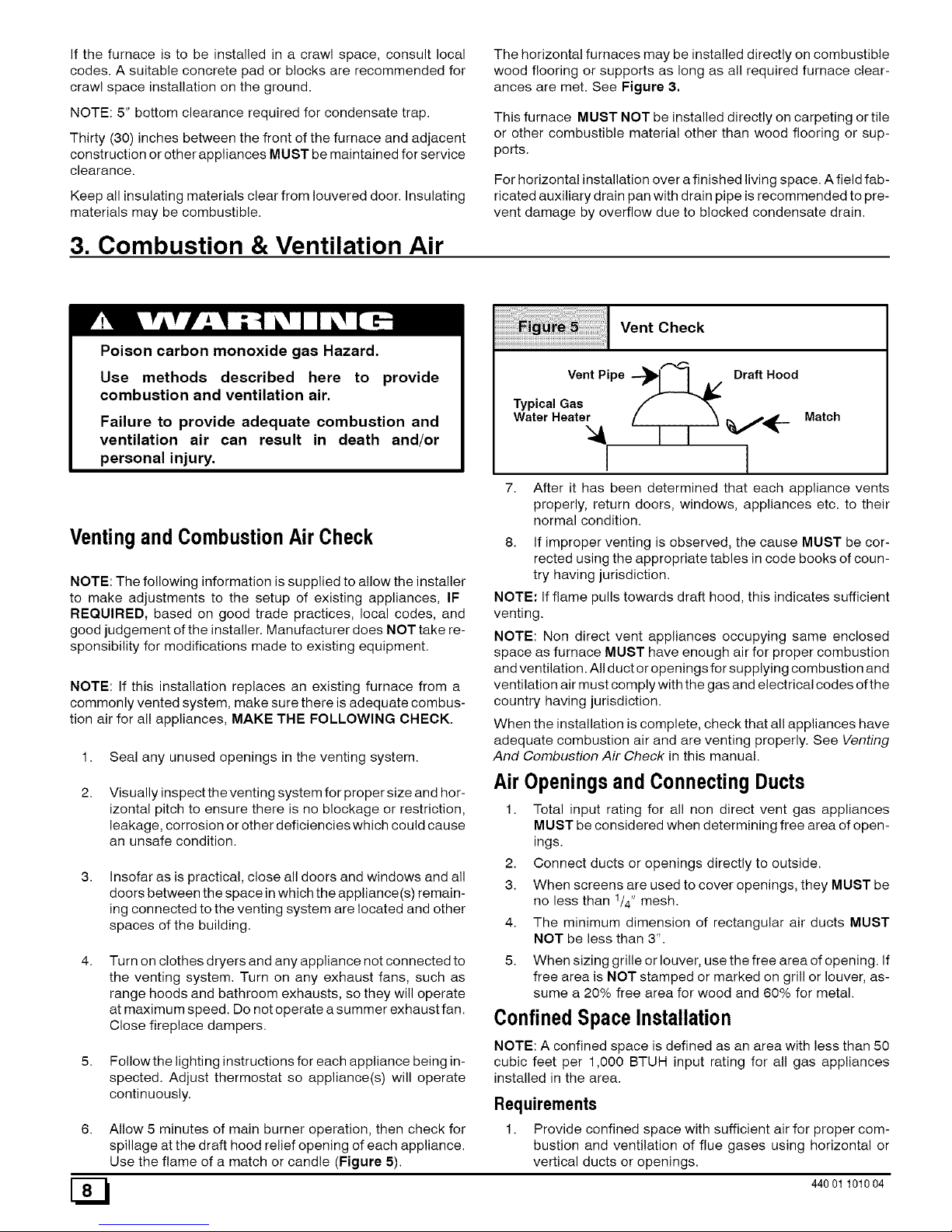
Vent Check
Use methods described here to provide
combustion and ventilation air.
Failure to provide adequate combustion and
ventilation air can result in death and/or
personal injury.
Ventingand CombustionAir Check
NOTE: The following information is supplied to allow the installer
to make adjustments to the setup of existing appliances, IF
REQUIRED, based on good trade practices, local codes, and
good judgement of the installer. Manufacturer does NOT take re-
sponsibility for modifications made to existing equipment.
NOTE: If this installation replaces an existing furnace from a
commonly vented system, make sure there is adequate combus-
tion air for all appliances, MAKE THE FOLLOWING CHECK.
1. Seal any unused openings in the venting system.
Visually inspect the venting system for proper size and hor-
izontal pitch to ensure there is no blockage or restriction,
leakage, corrosion or other deficiencies which could cause
an unsafe condition.
Insofar as is practical, close all doors and windows and all
doors between the space in which the appliance(s) remain-
ing connected to the venting system are located and other
spaces of the building.
Vent Pipe--_ I A/ Draft Hood
Typical Gas
WaterHeater / Matc.
I I
I 1
7. After it has been determined that each appliance vents
properly, return doors, windows, appliances etc. to their
normal condition.
8. If improper venting is observed, the cause MUST be cor-
rected using the appropriate tables in code books of coun-
try having jurisdiction.
NOTE: if flame pulls towards draft hood, this indicates sufficient
venting.
NOTE: Non direct vent appliances occupying same enclosed
space as furnace MUST have enough air for proper combustion
and ventilation. All duct or openings for supplying combustion and
ventilation air must comply with the gas and electrical codes of the
country having jurisdiction.
When the installation is complete, check that all appliances have
adequate combustion air and are venting properly. See Venting
And Combustion Air Check in this manual.
Air Openingsand ConnectingDucts
1. Total input rating for all non direct vent gas appliances
MUST be considered when determining free area of open-
ings.
2. Connect ducts or openings directly to outside.
3. When screens are used to cover openings, they MUST be
no less than 1/4" mesh.
4. The minimum dimension of rectangular air ducts MUST
NOT be less than 3".
G3
Turn on clothes dryers and any appliance not connected to
the venting system. Turn on any exhaust fans, such as
range hoods and bathroom exhausts, so they will operate
at maximum speed. Do not operate a summer exhaust fan.
Close fireplace dampers.
Followthe lighting instructions for each appliance being in-
spected. Adjust thermostat so appliance(s) will operate
continuously.
Allow 5 minutes of main burner operation, then check for
spillage at the draft hood relief opening of each appliance.
Use the flame of a match or candle (Figure 5).
5. When sizing grille or louver, use the free area of opening. If
free area is NOT stamped or marked on grill or louver, as-
sume a 20% free area for wood and 60% for metal.
Confined SpaceInstallation
NOTE: A confined space is defined as an area with less than 50
cubic feet per 1,000 BTUH input rating for all gas appliances
installed in the area.
Requirements
1. Provide confined space with sufficient air for proper com-
bustion and ventilation of flue gases using horizontal or
vertical ducts or openings.
44001 101004
Page 9
3.
4.
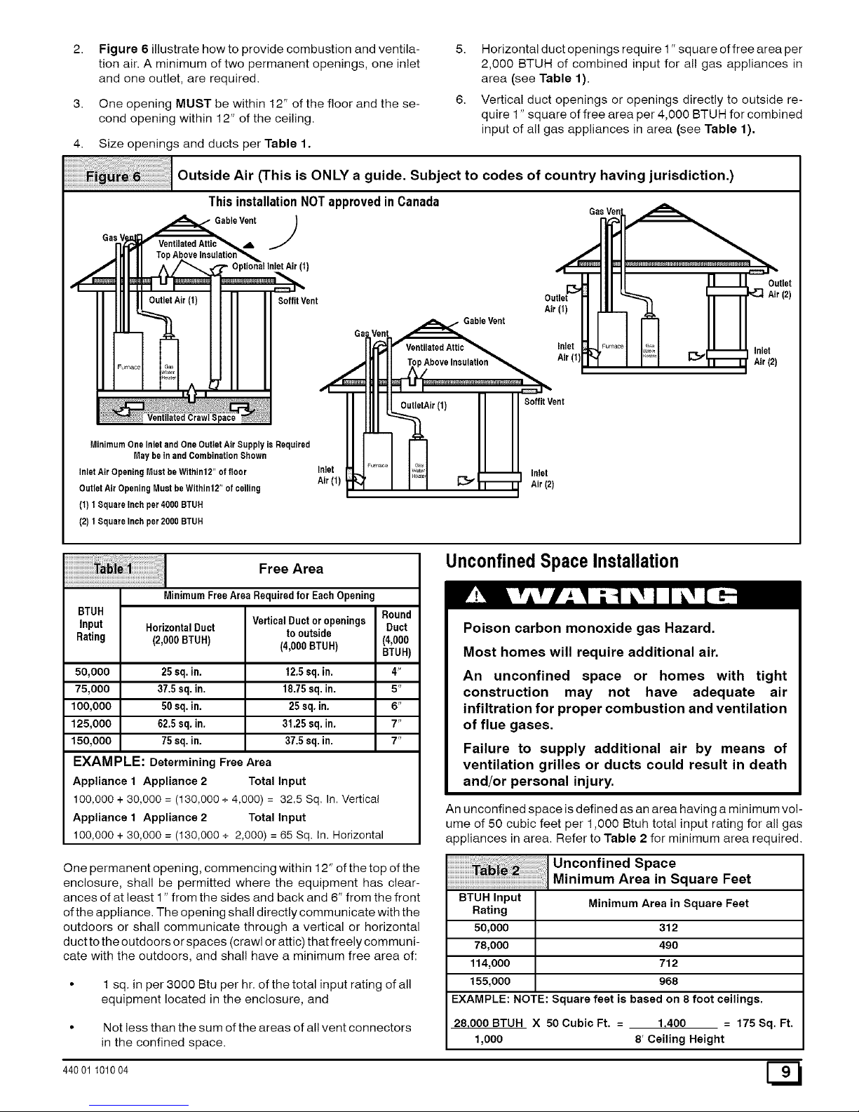
Figure 6 illustrate how to provide combustion and ventila-
tion air. A minimum of two permanent openings, one inlet
and one outlet, are required.
One opening MUST be within 12" of the floor and the se-
cond opening within 12" of the ceiling.
Size openings and ducts per Table 1.
5. Horizontal duct openings require 1" square offree area per
2,000 BTUH of combined input for all gas appliances in
area (see Table 1).
6. Vertical duct openings or openings directly to outside re-
quire 1" square of free area per 4,000 BTUH for combined
input of all gas appliances in area (see Table 1).
Outside Air (This is ONLY a guide. Subject to codes of country having jurisdiction.)
ThisinstallationNOTapprovedinCanada
GableVent_b.J
- OptionalInlet Air (t)
I II I -- I
_Air (t)
wate_
SoffitVent
Gable Vent
Air (t)
Inlet
Air (t]
Soffit Vent
MinimumOneInlet and One OutletAir Supply is Required
May beinandCombinationShown
InletAir OpeningMust be Within12"offloor
OutletAir OpeningMustbeWithin12" of ceiling
(t) t SquareInch per4000 BTUH
(2)t SquareInch per2000 BTUH
Inlet
Air(t)
Inlet
Air (2)
MinimumFree Area Requiredfor Each Opening
BTUH
input HorizontalDuct
Rating (2,000BTUH)
50,000 25 sq.in.
75,000 37.5sq. in.
100,000 50sq.in.
125,000 62.5sq. in.
150,000 75sq. in.
VerticalDuctoropenings Round
to outside Duct
(4,000BTUH) (4,000
BTUH)
12.5sq.in. 4"
18.75sq. in. 5"
25sq. in. 6"
31.25sq, in. 7"
37.5sq. in. 7"
EXAMPLE: Determining Free Area
Appliance 1 Appliance 2 Total Input
100,000 + 30,000 = (130,000 + 4,000) = 32.5 Sq. In. Vertical
Appliance 1 Appliance 2 Total Input
100,000 + 30,000 = (130,000 + 2,000) = 65 Sq. In. Horizontal
One permanent opening, commencing within 12" of the top of the
enclosure, shall be permitted where the equipment has clear-
ances of at least 1" from the sides and back and 6" from the front
of the appliance. The opening shall directly communicate with the
outdoors or shall communicate through a vertical or horizontal
duct to the outdoors or spaces (crawl or attic) that freely communi-
cate with the outdoors, and shall have a minimum free area of:
• 1sq. in per 3000 Btu per hr. of the total input rating of all
equipment located in the enclosure, and
• Not less than the sum of the areas of all vent connectors
in the confined space.
UnconfinedSpaceInstallation
Poison carbon monoxide gas Hazard,
Most homes will require additional air.
An unconfined space or homes with tight
construction may not have adequate air
infiltration for proper combustion and ventilation
of flue gases.
Failure to supply additional air by means of
ventilation grilles or ducts could result in death
and/or personal injury.
BTUH Input
Rating
50,000
78,000
114,000
155,000
An unconfined space is defined as an area having a minimum vol-
ume of 50 cubic feet per 1,000 Btuh total input rating for all gas
appliances in area. Refer to Table 2 for minimum area required.
I Unconfined Space
Minimum Area in Square Feet
Minimum Area in Square Feet
312
490
712
968
EXAMPLE: NOTE: Square feet is based on 8 foot ceilings,
28,000BTUH X 50CubicFt. = 1,400 = 175Sq. Ft.
1,000 8' Ceiling Height
44001 101004
Page 10
NOTE:Referto definitionsin sectiontitledUnusually Tight
Construction. If any one of the conditions apply, the space MUST
be considered confined space regardless of size.
1. Adjoining rooms can be considered part of an unconfined
area if there are openings without doors between rooms.
2. An attic or crawl space may be considered an unconfined
space provided there are adequate ventilation openings di-
rectly to outdoors. Openings MUST remain open and NOT
have any means of being closed off. Ventilation openings to
outdoors MUST be at least 1" square of free area per 4,000
BTUH of total input rating for all gas appliances in area.
3. Install air intake a minimum of 12" above maximum snow
level and clear of any obstruction. Duct or ventilation open-
ing requires one square inch of free area per 4,000 BTUH
of total input rating for all gas appliances in area.
4. Air inlet MUST be screened with not less than 1/4" mesh
screen.
UnusuallyTight Construction
In unconfined spaces, infiltration may be adequate to provide air
for combustion, ventilation and dilution of flue gases. However, in
buildings with unusually tight construction, additional air MUST
be provided using the methods described in section titled Con-
fined Space Installation:
Unusually tight construction is defined as: Construction with
2.
3.
Walls and ceilings exposed to the outside have a continu-
ous, sealed vapor barrier. Openings are gasketed or
sealed and
Doors and openable windows are weather stripped and
Other openings are caulked or sealed. These include joints
around window and door frames, between sole plates and
floors, between wall-ceiling joints, between wall panels, at
penetrations for plumbing, electrical and gas lines, etc.
VentilationAir
Some provincial codes and local municipalities require ventilation
or make-up air be brought into the conditioned space as replace-
ment air. Whichever method is used, the mixed return air temper-
ature across the heat exchanger MUST not fall below 60 °F or flue
gases will condense in the heat exchanger. This will shorten the
life of the heat exchanger and possibly void your warranty.
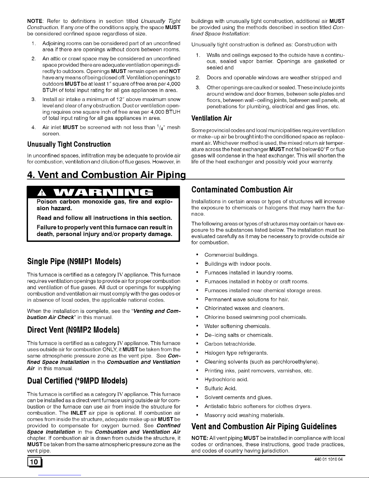
4. Vent and Combustion Air Piping
Poison carbon monoxide gas, fire and explo-
sion hazard,
Contaminated Combustion Air
Read and follow all instructions in this section,
Failure to properly vent this furnace can result in
death, personal injury and/or property damage.
Installations in certain areas or types of structures will increase
the exposure to chemicals or halogens that may harm the fur-
nace.
The following areas or types of structures may contain or have ex-
posure to the substances listed below. The installation must be
evaluated carefully as it may be necessary to provide outside air
for combustion.
SinglePipe(NgMP1Models)
This furnace is certified as a category IV appliance. This furnace
requires ventilation openings to provide air for proper combustion
and ventilation of flue gases. All duct or openings for supplying
combustion and ventilation air must comply with the gas codes or
in absence of local codes, the applicable national codes.
When the installation is complete, see the "Venting and Com-
bustion Air Check" in this manual.
DirectVent(NgMP2Models)
This furnace is certified as a category IV appliance. This furnace
uses outside air for combustion ONLY, it MUST be taken from the
same atmospheric pressure zone as the vent pipe. See Con-
fined Space Installation in the Combustion and Ventilation
Air in this manual.
DualCertified (*9MPDModels)
This furnace is certified as a category IV appliance. This furnace
can be installed as a direct vent furnace using outside air for com-
bustion or the furnace can use air from inside the structure for
combustion. The INLET air pipe is optional. If combustion air
comes from inside the structure, adequate make up air MUST be
• Commercial buildings.
• Buildings with indoor pools.
• Furnaces installed in laundry rooms.
• Furnaces installed in hobby or craft rooms.
• Furnaces installed near chemical storage areas.
• Permanent wave solutions for hair.
• Chlorinated waxes and cleaners.
• Chlorine based swimming pool chemicals.
• Water softening chemicals.
• De-icing salts or chemicals.
• Carbon tetrach!oride.
• Halogen type refrigerants.
• Cleaning solvents (such as perch!oroethylene).
• Printing inks, paint removers, varnishes, etc.
• Hydrochloric acid.
• Sulfuric Acid.
• Solvent cements and glues.
• Antistatic fabric softeners for clothes dryers.
• Masonry acid washing materials.
provided to compensate for oxygen burned. See Confined
Space Installation in the Combustion and Ventilation Air
chapter, if combustion air is drawn from outside the structure, it
MUST be taken from the same atmospheric pressure zone as the
vent pipe.
Ventand Combustion Air PipingGuidelines
NOTE: All vent piping MUST be installed in compliance with local
codes or ordinances, these instructions, good trade practices,
and codes of country having jurisdiction.
44001 101004
Page 11
1. Determinethebestroutingandterminationforthevent
pipeandairinletpipebyreferringtoalloftheinstructions
andguidelinesinthisSection.
2. Determinethesizerequiredfortheventpipeandairinlet
pipe.
3. Looselyassembleallventingpartswithoutadhesive(pipe
jointcement)forcorrectfitbeforefinalassembly.
4. Useofverticalpipingispreferredbecausetherewillbe
somemoistureinthefluegasesthatmaycondenseasit
leavestheventpipe(SeeSpecial Instruction For Horizon-
tal Vents).
5. The vertical vent pipe MUST be supported so that no
weight is allowed to rest on the combustion blower.
6. Exhaust vent piping or air inlet piping diameter MUST NOT
be reduced.
7.
All exhaust vent piping from the furnace to termination
MUST slope upwards. A minimum of 1/4" per foot of run is
required to properly return condensate to the furnace drain
system.
8. Use DWV type long radius elbows whenever possible, as
they provide for the minimum slope on horizontal runs and
they provide less resistance in the vent system. If DWV el-
bows cannot be used, use two, 45 ° elbows when possible.
On horizontal runs the elbows can be slightly misaligned to
provide the correct slope.
9. All horizontal pipe runs MUST be supported at least every
five feet with galvanized strap or other rust resistant materi-
al. NO sags or dips are permitted.
10. All vertical pipe runs MUST be supported every six feet
where accessible.
11. The minimum pipe run length is 2'.
12. The piping can be run in the same chase or adjacent to sup-
ply or vent pipe for water supply or waste plumbing. It can
also be run in the same chase with a vent from another 90+
furnace.
NOTE: In NO case can the piping be run in a chase where
temperatures can exceed 140 ° R or where radiated heat
from adjacent surfaces would exceed 140 ° F.
13. The vent outlet MUST be installed to terminate in the same
atmospheric pressure zone as the combustion air inlet.
14. The vent system can be installed in an existing unused
chimney provided that:
• Both the exhaust vent and air intake run the length ofthe
chimney.
• No other gas fired appliance or fireplace (solid fuel) is
vented into the chimney.
• The top of the chimney MUST be sealed flush or
crowned up to seal against rain or melting snow so ONLY
the piping protrudes,
• The termination clearances shown in Figure 7 are main-
tained.
15. Furnace applications with vertical vents requiring vent di-
ameter increaser fittings must have increaser fittings
installed in vertical portion of the vent. Condensate will be
trapped in the vent if the vent diameter is increased prior to
having an elbow turned upward. This could cause nui-
sance tripping of the pressure switch.
PipingInsulation Guidelines
NOTE: Use closed cell, neoprene insulation or equivalent. If Fi-
berglass or equivalent insulation is used it must have a vapor bar-
rier. Use R values of 7 up to 10', R- 11 if exposure exceeds 10'. If
Fiberglass insulation is used, exterior to the structure, the pipe
MUST be boxed in and sealed against moisture.
1. When the vent or combustion air pipe height above the roof
exceeds 30", or if an exterior vertical riser is used on a hori-
zontal vent to get above snow levels, the exterior portion
MUST be insulated.
2. When combustion air inlet piping is installed above a sus-
pended ceiling, the pipe MUST be insulated with moisture
resistant insulation such as Armaflex or other equivalent
type of insulation.
3. Insulate combustion air inlet piping when run in warm, hu-
mid spaces such as basements.
Sizing Combustion Air and VentPipe
Consult Table 3 or Table 4 to select the proper diameter exhaust
and combustion air piping. Exhaust and combustion air piping is
sized for each furnace Btuh size based on total lineal vent length
(on inlet or outlet side), and number of 90 ° elbows required.
1. Double Pipe Installation-If installing as a direct-vent ap-
pliance, consult Table 4 to select the proper diameter ex-
haust and combustion air piping. Exhaust and combustion
air piping is sized for each furnace Btuh size based on total
lineal vent length (on inlet or outlet side), and number of 90 °
elbows required.
2. Single Pipe Installation-if installing as a non-direct vent
appliance, (single outlet pipe and no inlet pipe) refer to
Table 3. The table shows the maximum number of elbows
allowed with any given pipe diameter and length of run.
3. Use of Elbows-Two 45 ° elbows can be substituted for one
90 ° elbow. The elbow or elbows used for vent termination
outside the structure ARE counted, including elbows need-
ed to bring termination above expected snow levels.
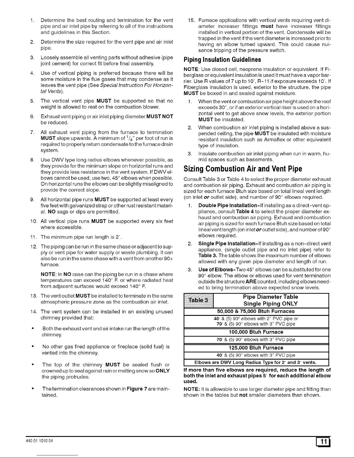
Pipe Diameter Table
Single Piping ONLY
50,000 & 75,000 Btuh Furnaces
40' & (5) 90° elbows with 2" PVC pipe or
70' & (5) 90 ° elbows with 3" PVC pipe
100,000 Btuh Furnace
70' & (5) 90 ° elbows with 3" PVC pipe
125,000 Btuh Furnace
40' & (5) 90 ° elbows with 3" PVC pipe
Elbows are DWV Long Radius Type for 2" and 3" vents.
If more than five elbows are required, reduce the length of
both the inlet and exhaust pipes 5' for each additional elbow
used.
NOTE: It is allowable to use larger diameter pipe and fitting than
shown in the tables but not smaller diameters than shown.
44001 101004 [_1
Page 12
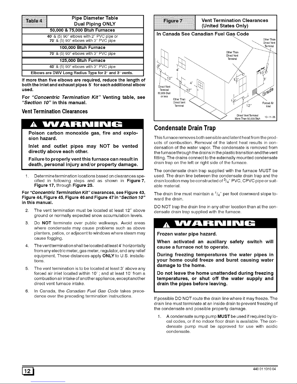
Pipe Diameter Table
Dual Piping ONLY
50,000 & 75,000 Btuh Furnaces
40' & (5) 90 ° elbows with 2" PVC pipe or
70' & (5) 90 ° elbows with 3" PVC pipe
100,000 Btuh Furnace
70' & (5) 90 ° elbows with 3" PVC pipe
125,000 Btuh Furnace
40' & (5) 90 ° elbows with 3" PVC pipe
Elbows are DWV Long Radius Type for 2" and 3" vents.
If more than five elbows are required, reduce the length of
both the inlet and exhaust pipes 5' for each additional elbow
used.
For "Concentric Termination Kit" Venting table, see
"Section 10" in this manual.
VentTermination Clearances
Poison carbon monoxide gas, fire and explo-
sion hazard.
Inlet and outlet pipes may NOT be vented
directly above each other.
Failure to properly vent this furnace can result in
death, personal injury and/or property damage.
1. Determinetermination locations based on clearances spe-
cified in following steps and as shown in Figure 7,
Figure 17, through Figure 25.
For "Concentric Termination Kit" clearances, see Figure 43,
Figure 44, Figure 45, Figure 46and Figure 47 in "Section 10"
in this manual.
2. The vent termination must be located at least 12" above
ground or normally expected snow accumulation levels.
3. Do NOT terminate over public walkways. Avoid areas
where condensate may cause problems such as above
planters, patios, or adjacent to windows where steam may
cause fogging.
4. The venttermination shall be located at least 4' horizontally
from any electric meter, gas meter, regulator, and any relief
equipment. These distances apply ONLY to U.S. installa-
tions.
The vent termination is to be located at least 3' above any
forced air inlet located within 10' ; and at least 10' from a
combustion air intake of another appliance, except another
direct vent furnace intake.
6. In Canada, the Canadian Fuel Gas Code takes prece-
dence over the preceding termination instructions.
Vent Termination Clearances
(United States Only)
OtherThan
OtherThan
DirectVeflt
Terminal
DirectVent
Terminal
50,000Btuh
oriess
OtherThatl
DirectVent ForcedAir
Terminal 12" Inlet
DirectVentTerminal
10-1t-36
More Than 50,000 Btuh
CondensateDrainTrap
This furnace removes both sensible and latent heat from the prod-
ucts of combustion. Removal of the latent heat results in con-
densation of the water vapor. The condensate is removed from
the furnace through the drains in the plastic transition and the vent
fitting. The drains connect to the externally mounted condensate
drain trap on the left or right side of the furnace.
The condensate drain trap supplied with the furnace MUST be
used. The drain line between the condensate drain trap and the
3 ,
drain location may be constructed of /4' PVC, CPVC pipe or suit-
able material.
The drain line must maintain a 1/4" per foot downward slope to-
ward the drain.
DO NOT trap the drain line in any other location than at the con-
densate drain trap supplied with the furnace.
Frozen water pipe hazard.
When activated an auxiliary safety switch will
cause a furnace not to operate.
During freezing temperatures the water pipes in
your home could freeze and burst causing water
damage to the home.
Do not leave the home unattended during freezing
temperatures, or shut off the water supply and
drain the pipes before leaving.
If possible DO NOT route the drain line where it may freeze. The
drain line must terminate at an inside drain to prevent freezing of
the condensate and possible property damage.
1. A condensate sump pump MUST be used if required by lo-
cal codes, or if no indoor floor drain is available. The con-
densate pump must be approved for use with acidic
condensate.
[_ 44001 101004
Page 13
2. Apluggedcondensatedrainlineorafailedcondensate
pumpwillallowcondensateto spill.If thefurnaceis
installedwhereacondensatespillcouldcausedamage,it
isrecommendedthatanauxiliarysafetyswitchbeinstalled
topreventoperationoftheequipmentintheeventofpump
failureorpluggeddrainline.Ifused,anauxiliarysafety
switchshouldbeinstalledintheRcircuit(lowvoltage)
ONLY.
CondensateDrainTrapFreezeProtection
Special precautions MUST be made if installing furnace in an
area which may drop below freezing. This can cause improper op-
eration or damage to the equipment. If the the furnace environ-
ment has the potential of freezing, the drain trap and drain line
must be protected. Use 3 to 6 watt per foot at 115 volt, 40 ° F self-
regulating shielded and waterproof heat tape. Wrap the drain trap
and drain line with the heat tape and secure with the ties. Follow
the heat tape manufacturer's recommendations.
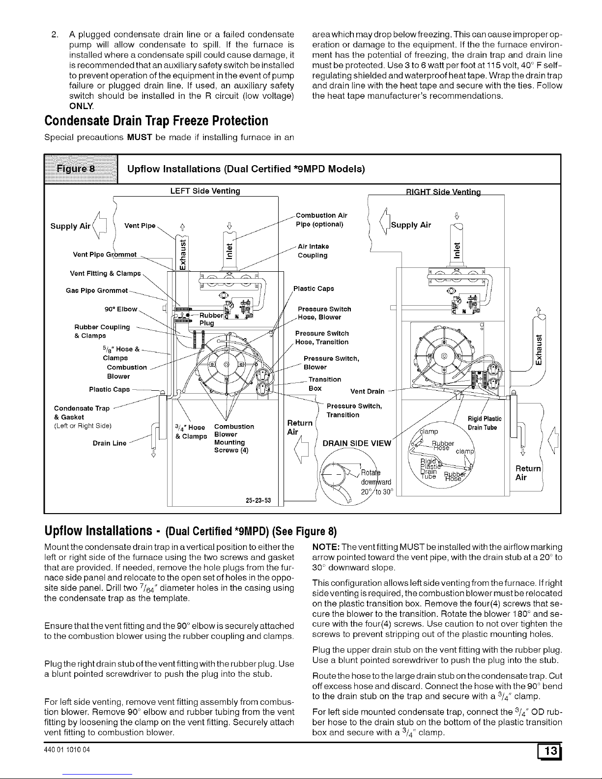
Upflow Installations (Dual Certified *9MPD Models)
LEFT Side Venting
Supply Air _ Vent Pipe
Vent Pipe
Vent Fittin,
Gas Pipe
90 ° Elbow
Rubber Coupling
&Clamps
5/8
Clamps
Combustion
Blower
Plastic
CondensateTrap _
& Gasket
(Left or Right Side)
Drain Line
Plug
3/4" Hose Combustion
& Clamps Blower
Mounting
Screws (4)
25-23-53
Pipe (optional)
lSupply Air
Coupling
Plastic Caps
Pressure Switch
Blower
Pressure Switch
Transition
Pressure Switch,
Transition
Box Vent Drain
Pressure Switch,
Transition
DRAIN SIDE VIEW _
:lamp
Rigid Plastic
Drain Tube
UpflowInstallations- (Dual Certified*9MPD) (See Figure8)
Mount the condensate drain trap in a vertical position to either the
left or right side of the furnace using the two screws and gasket
that are provided. If needed, remove the hole plugs from the fur-
nace side panel and relocate to the open set of holes in the oppo-
site side panel. Drill two 7/64" diameter holes in the casing using
the condensate trap as the template.
Ensure that the vent fitting and the 90 ° elbow is securely attached
to the combustion blower using the rubber coupling and clamps.
Plug the right drain stub of the vent fitting with the rubber plug. Use
a blunt pointed screwdriver to push the plug into the stub.
For left side venting, remove vent fitting assembly from combus-
tion blower. Remove 90 ° elbow and rubber tubing from the vent
fitting by loosening the clamp on the vent fitting. Securely attach
vent fitting to combustion blower.
44001 101004
NOTE: The vent fitting MUST be installed with the airflow marking
arrow pointed toward the vent pipe, with the drain stub at a 20 ° to
30 ° downward slope.
This configuration allows left side venting from the furnace. If right
sideventing is required, the combustion blower must be relocated
on the plastic transition box. Remove the four(4) screws that se-
cure the blower to the transition. Rotate the blower 180 ° and se-
cure with the four(4) screws. Use caution to not over tighten the
screws to prevent stripping out of the plastic mounting holes.
Plug the upper drain stub on the vent fitting with the rubber plug.
Use a blunt pointed screwdriver to push the plug into the stub.
Route the hose to the large drain stub on the condensate trap. Cut
off excess hose and discard. Connect the hose with the 90 ° bend
to the drain stub on the trap and secure with a 3/4" clamp.
For left side mounted condensate trap, connect the 3/4" OD rub-
ber hose to the drain stub on the bottom of the plastic transition
box and secure with a 3/4" clamp.
Page 14

For right side mounted condensate trap, the rigid plastic drain
tube MUST be used, Cut two 2" long sections from the 3/4" OD
rubber hose, Connect the plastic drain tube to the drain stub on
the bottom of the plastic transition box and to the stub on the con-
densate trap using the two hose sections and 3/4" clamps.
Route the hose to the small drain stub on the condensate trap. Cut
off excess hose and discard. Connect the hose to the drain stub
on the trap and secure with a 5/8" clamp.
NOTE: The support leg on the plastic drain tube MUST be posi-
tioned on the blower partition.
Connect the 5/8" OD rubber hose with the 90 ° bend to the left
drain stub on the vent fitting and secure with a 5/8" clamp.
NOTE: Ensure hoses maintain a downward slope to the conden-
sate trap with no kinking or binding for proper condensate drain-
age.
Horizontal Left Installations (Dual Certified *9MPD)
Transition Box
Air Intake Combustion Air Pipe, (optional)
ly =
J_
x
LU
Vent Fitting
Elbow
Preasure Switch Hose,
Blower
Preaaure Switch,
Blower Pressure Switch,
_ Transition
Combustion
Combustion Blower
Mounting Screws
(4)
Transition
3/4" Hose & Clamps
Return
Air
Vent Pipe
Grommet
DRAIN SIDE VIEW
Gas Pipe
Grommet
Trap & Gasket
5/8" Hose & Clamps
Rotatedownward Rubber Coupling
20° to30° & Clamps
dwg 25-23-54
HorizontalLeftInstallations- (Dual Certified*9MPD) (See Figure 9)
Relocate the plastic caps and clamps on the condensate drain
trap from the vertical drain stub to the horizontal drain stubs. Se-
cure the clamps tightly to prevent condensate leakage,
Mount the condensate drain trap in a vertical position to the left
side of the furnace using the two screws and gasket that are pro-
vided. Note: The condensate trap will be located under the fur-
nace in a vertical position when the furnace is placed horizontally
on the left side. If needed, remove the hole plugs from the furnace
side panel and relocate to the open set of holes in the opposite
side panel. Drill two 7/64" diameter holes in the casing using the
condensate trap as the template.
Connect the vent fitting and the 90 ° elbow to the combustion blow-
er using the rubber coupling and clamps.
Plug the upper drain stub on the vent fitting with the rubber plug.
Use a blunt pointed screwdriver to push the plug into the stub.
Connect the 3/4" OD rubber hose with the 90 ° bend to the drain
stub on the bottom of the plastic transition box and secure with a
3/4" clamp.
Route the hose to the large drain stub on the condensate trap. Cut
oft excess hose and discard. Connect the hose to the drain stub
on the trap and secure with a 3/4" clamp.
Connect the 5/8" OD rubber hose with the 90 ° bend to the small
drain stub on the trap and secure with a 5/8" clamp.
Route the hose to the lower drain stub on the vent fitting. Cut oft
excess hose and discard. Connect the hose to the drain stub on
the vent fitting and secure with a 5/8" clamp.
NOTE: The vent fitting MUST be installed with the airflow marking
arrow pointed toward the vent pipe, with the drain stub at a 20 to
30° downward slope.
NOTE: Ensure hoses maintain a downward slope to the conden-
sate trap with no kinking or binding for proper condensate drain-
age.
[_ 44001 101004
Page 15

Return
Air
Horizontal Right Installations (Dual Certified *9MPD)
Rubber Coupling & Clamps 90° Elbow
Plastic Caps
5/8" Hose & Clamps
Combustion
Blower
Vent Fitting
Combustion Blower
Mounting
Screws (4)
Pressure Switch
Hose, Transition
Pressure Switch, Transition
i r
Combustion
Air Pipe
_(Optional)
Supply I
Air
/
Air Intake
Coupling
Plastic Caps
Condensate Trap
& Gasket
Drain Line
Pressure Switch, Hose, Blower ;IDE VIEW
Blower
3/4" Hose & Clamps
Rotatedownward
20° to30°
dwg25-23-55
HorizontalRight Installations- (DualCertified
Relocate the plastic caps and clamps on the condensate drain
trap from the vertical drain stub to the horizontal drain stubs. Se-
cure the clamps tightly to prevent condensate leakage.
*9MPD)(See Figure 10)
Relocate the plastic caps on the stubs of the plastic transition box
from the lower stubs to the upper stubs and secure tightly with the
clamps.
Mount the condensate drain trap in a vertical position to the right
side of the furnace using the two screws and gasket that are pro-
vided. Note: The condensate trap will be located under the fur-
nace in a vertical position when the furnace is placed horizontally
on the right side. If needed, remove the hole plugs from the fur-
nace side panel and relocated to the open set of holes in the oppo-
site side panel. Drill two 7/64" diameter holes in the casing using
the condensate trap as the template.
Route the pressure switch hose to the lower stub on the plastic
transition box. Cut off excess hose and discard. Connect the pres-
sure switch hose to the lower stub on the plastic transition box.
NOTE: Failure to correctly install the pressure switch hose to the
transition can adversely affect the safety control operation.
Connect the 3/4" OD rubber hose with the 90 ° bend to the drain
stub on the bottom of the plastic transition box and secure with a
3/4" clamp.
Connect the vent fitting and the 90 ° elbow to the combustion blow-
er using the rubber coupling and clamps.
Route the hose to the large drain stub on the condensate trap. Cut
off excess hose and discard. Connect the hose to the drain stub
on the trap and secure with a 3/4" clamp.
NOTE: The vent fitting MUST be installed with the airflow marking
arrow pointed toward the vent pipe, with the drain stub at a 20 ° to
30 ° downward slope.
Plug the upper drain stub on the vent fitting with the rubber plug.
Use a blunt pointed screwdriver to push the plug into the stub.
Remove the pressure switch hose from the upper stub on the
plastic transition box,
Connect the 5/8" OD rubber hose with the 90 ° bend to the lower
drain stub on the vent fitting and secure with a 5/8" clamp.
Route the hose to the smaller drain stub on the condensate trap.
Cut off excess hose and discard. Connect the hose to the drain
stub on the trap and secure with a 5/8" clamp.
NOTE: Ensure hoses maintain a downward slope to the conden-
sate trap with no kinking or binding for proper condensate drain-
age.
44001 101004 [_
Page 16

Downflow Installations (Dual Certified *gMPD Models)
LEFT Side Venting_
"4C>
Return Air
Combustion Blower
Mounting Screws (4)
Supply Air
Pressure Switch,
Transition
Pressure Switch
Hose, Transition _
Blower
Pressure Switch
Hose,
3/4
& Clamps
5/8°
Clamps
RIGHT Side Venting
<z>
Return Air
Combustion Blower
0
Transition
Box
Supply Air
Air Intake
Coupling
Combustion
Air Pipe, (Optional)
Vent Pipe
__e_ltFittin g
mps
Vent Pipe
Grommet
Caps
Condensate
Trap & Gasket
pe
Grommet
Drain Line
dwg 25-23-56
Downfl0wInstallations- (DualCertified*9MPDModels)(See Figure 11)
Mount the condensate drain trap in a vertical position to either the
right or left side of the furnace using the two screws and gasket
that are provided. If needed, remove the hole plugs from the fur-
nace side panel and relocated to the open set of holes in the oppo-
site side panel. Drill two 7/64" diameter holes in the casing using
the condensate trap as the template.
Ensure that the vent fitting and the 90 ° elbow is securely attached
to the combustion blower using the rubber coupling and clamps.
This configuration allows right side venting from the furnace. Ifthe
left side venting is required, the combustion blower must be relo-
cated on the plastic transition box. Remove the four(4) screws
that secure the blower to the transition. Rotate the blower 180 °
and secure with the four(4) screws. Use caution to not over tight-
en the screws to prevent stripping out of the plastic mounting
holes.
For right side venting, remove vent fitting assembly from combus-
tion blower. Remove 90° elbow and rubber tubing from the vent
fitting by loosening the clamp on the vent fitting. Securely attach
vent fitting to combustion blower.
NOTE: The vent fitting MUST be installed with the airflow marking
arrow pointed toward the vent pipe, with the drain stub at a 20 ° to
30° downward slope.
Plug the upper drain stub of the vent fitting with the rubber plug.
Use a blunt pointed screwdriver to push the plug into the stub.
Remove the pressure switch hose from the upper stub on the
plastic transition box.
Relocate the plastic caps on the stubs of the plastic transition box
from the lower stubs to the upper stubs and secure tightly with the
clamps.
Route the pressure switch hose to the lower stub on the plastic
transition box. Cut off excess hose and discard. Connect the pres-
sure switch hose to the lower stub on the plastic transition box.
NOTE: Failure to correctly install the pressure switch hose to the
transition box can adversely affect the safety control operation.
Connect the 3/4" OD rubber hose with the 90 ° bend to the drain
stub on the bottom of the plastic transition box and secure with a
3/4" clamp.
Route the hose to the large drain stub on the condensate trap. Cut
off excess hose and discard. Connect the hose to the drain stub
on the trap and secure with a 3/4" clamp.
Connect the 5/8" OD rubber hose with the 90 ° bend to the left
drain stub on the vent fitting and secure with a 5/8" clamp.
Route the hose to the smaller stub on the condensate trap. Cut off
excess hose and discard. Connect the hose to the drain stub on
the trap and secure with a 5/8" clamp.
NOTE: Ensure hoses maintain a downward slope to the conden-
sate trap with no kinking or binding for proper condensate drain-
age.
[_ 44001 101004
Page 17

Vent Fitting
& Clamps
5/8" Hose & Clamps --
Plastic
Caps
Condensate
Trap & Gasket
LEFT Side Venting
Supply Air
Upflow Installations (Single Pipe & Direct Vent NgMP1 & NgMP2 Models)
RIGHT Side Venting
Combustion
/ Air Pipe, /1
NgMP2ONLY _ Supply Air _
Rubbe_
P,ug
Transition Box
Plastic
Caps
Combustion Blower
180° for
Left Side)
Pressure Hose,
Blower
Pressure Switch,
Blower
Pressure Switch
Hose, Transition
Pressure Switch,
Transition
DRAIN SIDE VIEW
_ ombustion
Air Pipe,
NgMP2 ONLY
Combustion
Blower
Mounting
3/4" Hose & Clamps
dwg 25-23-57
Upfl0wInstallations-
Mount the condensate drain trap in a vertical position to either the
left or right side of the furnace using the two screws and gasket
that are provided. If needed, remove the hole plugs from the fur-
nace side panel and relocate to the open set of holes in the oppo-
site side panel. Drill two 7/64" diameter holes in the casing using
the condensate trap as the template.
(Single Pipe &Direct Vent NgMP1& NgMP2 Models) (See Figure 12)
For left side mounted condensate trap, connect the 3/4" OD rub-
ber hose with the 90 ° bend to the drain stub on the bottom of the
plastic transition box and secure with a 3/4" clamp.
Route the hose to the large drain stub on the condensate trap. Cut
off excess hose and discard. Connect the hose to the drain stub
on the trap and secure with a 8/4" clamp.
Ensure that the vent fitting and the 90 ° elbow is securely attached
to the combustion blower using the rubber coupling and clamps.
NOTE: The vent fitting MUST be installed with the airflow marking
arrow pointed toward the vent pipe, with the drain stub at a 20 ° to
30 ° downward slope.
This configuration allows left side venting from the furnace. If right
side venting is required, the combustion blower must be relocated
on the plastic transition box. Remove the four(4) screws that se-
cure the blower to the transition. Rotate the blower 180 ° and se-
cure with the four(4) screws. Use caution to not over tighten the
screws to prevent stripping out of the plastic mounting holes.
Plug the upper drain stub of the vent fitting with the rubber plug.
Use a blunt pointed screwdriver to push the plug into the stub.
For right side mounted condensate trap, the rigid plastic drain
tube MUST be used. Cut two 2" long sections from the 3/4" OD
rubber hose. Connect the plastic drain tube to the drain stub on
the bottom of the plastic transition box and to the stub on the con-
densate trap using the two hose sections and 8/4" clamps.
NOTE: The support leg on the plastic drain tube MUST be posi-
tioned on the blower partition.
Connect the 5/8" OD rubber hose with the 90 ° bend to the lower
drain stub on the vent fitting and secure with a 5/8" clamp.
Route the hose to the smaller drain stub on the condensate trap.
Cut off excess hose and discard. Connect the hose to the drain
stub on the trap and secure with a 5/8" clamp.
NOTE: Ensure hoses maintain a downward slope to the conden-
sate trap with no kinking or binding for proper condensate drain-
age.
44001 101004 [_
Page 18

Horizontal Left Installations (Single Pipe & Direct Vent NgMP1 & NgMP2 Models)
Plastic
Caps
Pressure Switch,
Blower Rubber
Plug
Transition
Grommet
Pressure Switch
Transition
Pressure Switch,
Supply
Air
?_> Inlet
/
Combustion
Air Pipe,
NgMP2ONLY
Vent Fitting
& Clamps
Pressure Switch
Hose, Blower
Combustion Blower
5/8" Hose &
Clamps
Return
Air
Combustion Blower
(Rotate 180 ° for Right Side)
3/4" Hose
& Clamps
Condensate
Trap & Gasket
Caps
dwg 25-23-58
HorizontalLeft Installations- (SinglePipe& DirectVentN9MP1& N9MP2 Models)(See Figure 13)
Relocate the plastic caps and clamps on the condensate drain
trap from the vertical drain stubs to the horizontal drain stubs. Se-
cure the clamps tightly to prevent condensate leakage.
Mount the condensate drain trap in a vertical position to the left
side of the furnace using the two screws and gasket that are pro-
vided. Note: The condensate trap will be located under the fur-
nace in a vertical position when the furnace is placed horizontally
on the left side. If needed, remove the hole plugs from the furnace
side panel and relocated to the open set of holes in the opposite
side panel. Drill two 7/64" diameter holes in the casing using the
condensate trap as the template.
Relocate the combustion blower on the plastic transition box. Re-
move the four(4) screws that secure the blower to the transition
box. Rotate the blower 180 ° so the blower snout is pointing up and
secure with the four(4) screws. Use caution to not over tighten the
screws to prevent stripping out of the plastic mounting holes.
Ensure that the vent fitting and the 90 ° elbow is securely attached
to the combustion blower using the rubber coupling and clamps.
NOTE: The vent fitting MUST be installed with the airflow marking
arrow pointed toward the vent pipe, with the drain stub at a 20° to
30 ° downward slope.
Plug the left drain stub on the vent fitting with the rubber plug. Use
a blunt pointed screwdriver to push the plug into the stub.
Connect the 3/4" OD rubber hose with the 90° bend to the drain
stub on the bottom of the plastic transition box and secure with a
3/4" clamp.
Route the hose to the large drain stub on the condensate trap. Cut
off excess hose and discard. Connect the hose to the drain stub
on the trap and secure with a 3/4" clamp.
Connect the 5/8" OD rubber hose with the 90° bend to the right
drain stub on the vent fitting and secure with a 5/8"clamp.
Route the hose to the smaller drain stub on the condensate trap.
Cut off excess hose and discard. Connect the hose to the drain
stub on the vent fitting and secure with a 5/8" clamp.
NOTE: Ensure hoses maintain a downward slope to the conden-
sate trap with no kinking or binding for proper condensate drain-
age.
[_1 44001 101004
Page 19

Horizontal Right Installations (Single Pipe & Direct Vent N9MP1 & N9MP2 Models)
Transition Box Vent Pipe
Caps Vent Fitting Combustion
Air Pipe,
NgMP2ONLY
Return
Air
5/8" Hose &
Clamps _
Mounting Screws (4)
PressureSwitch _ Supply
Hose, Blower Air
J
Plastic 3/4" Hose
Caps Pressure Hose, Transition & Clamps
Switch, Transition
Condensate
Trap & Gasket
Drain Line
Pressure
Switch, Blower
dwg 25-23-59
HorizontalRight Installations- (SinglePipe&
Figure14)
Relocate the plastic caps and clamps on the condensate drain
trap from the vertical drain stub to the horizontal drain stubs. Se-
cure the clamps tightly to prevent condensate leakage.
Mount the condensate drain trap in a vertical position to the right
side of the furnace using the two screws and gasket that are pro-
vided. Note: The condensate trap will be located under the fur-
nace in a vertical position when the furnace is placed horizontally
on the right side. If needed, remove the hole plugs from the fur-
nace side panel and relocate to the open set of holes in the oppo-
site side panel. Drill two 7/64" diameter holes in the casing using
the condensate trap as the template.
Ensure that the vent fitting and the 90 ° elbow is securely attached
to the combustion blower using the rubber coupling and clamps.
NOTE: The vent fitting MUST be installed with the airflow marking
arrow pointed toward the vent pipe.
Plug the left drain stub on the vent fitting with the rubber plug. Use
a blunt pointed screwdriver to push the plug into the stub.
Remove the pressure switch hose from the upper stub on the
plastic transition box.
Relocate the plastic caps on the stubs of the plastic transition from
the lower stubs to the upper stubs and secure tightly with the
clamps.
DirectVent NgMP1& NgMP2Models)(See
Route the hose to the large drain stub on the condensate trap. Cut
oft excess hose and discard. Connect the pressure switch hose
to the lower stub on the plastic transition box. NOTE: Failure to
correctly install the pressure switch hose to the transition can ad-
versely affect the safety control operation.
Connect the 3/4" OD rubber hose with the 90 ° bend to the drain
stub on the bottom of the plastic transition box and secure with a
3/4" clamp.
Route the hose to the large drain stub on the condensate trap. Cut
oft excess hose and discard. Connect the hose to the drain stub
on the trap and secure with a 3/4" clamp.
Connect the 5/8" OD rubber hose with the 90 ° bend to the right s-
tub on the vent fitting and secure with a 5/8" clamp.
Route the hose to the smaller drain stub on the condensate trap.
Cut oft excess hose and discard. Connect the hose to the drain
stub on the trap and secure with a 5/8" clamp.
NOTE: Ensure hoses maintain a downward slope to the conden-
sate trap with no kinking or binding for proper condensate drain-
age.
44001 101004 [_
Page 20
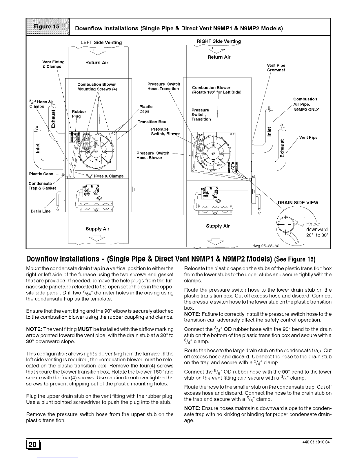
Downflow Installations (Single Pipe & Direct Vent NBMP1 & NBMP2 Models)
Vent Fitting
& Clamps
5/8" Hose &
Plastic Caps
Trap & Gasket
Drain Line
LEFT Side Venting RIGHT Side Venting
<z> <Z>
Return Air
Return Air
Combustion Blower
Mounting Screws (4)
Hose & Clamps
Supply Air
Pressure Switch
Hose, Transition
Plastic
Transition Box
Pressure
Switch, Blowe_rr
Pressure Switch
Hose, Blower
Combustion Blower
(Rotate 180° for Left Side)
Pressure
Switch,
Transition
Supply Air
dwg
Vent Pipe
Grommet
Combustion
NBMP2 ONLY
DRAIN SIDE VIEW
Rotate
downward
20° to 30°
D0wnfl0wInstallations- (Single Pipe& Direct
Mount the condensate drain trap in a vertical position to either the
right or left side of the furnace using the two screws and gasket
that are provided. If needed, remove the hole plugs from the fur-
nace side panel and relocated to the open set of holes in the oppo-
site side panel. Drill two 7/64" diameter holes in the casing using
the condensate trap as the template.
Ensure that the vent fitting and the 90 ° elbow is securely attached
to the combustion blower using the rubber coupling and clamps.
NOTE: The vent fitting MUST be installed with the airflow marking
arrow pointed toward the vent pipe, with the drain stub at a 20 ° to
30 ° downward slope.
This configuration allows right side venting from the furnace. Ifthe
left side venting is required, the combustion blower must be relo-
cated on the plastic transition box. Remove the four(4) screws
that secure the blower transition box. Rotate the blower 180 ° and
secure with the four(4) screws. Use caution to not over tighten the
screws to prevent stripping out of the plastic mounting holes.
Plug the upper drain stub on the vent fitting with the rubber plug.
Use a blunt pointed screwdriver to push the plug into the stub.
Remove the pressure switch hose from the upper stub on the
plastic transition.
VentN9MP1& N9MP2 Models)(See Figure 15)
Relocate the plastic caps on the stubs of the plastic transition box
from the lower stubs to the upper stubs and secure tightly with the
clamps.
Route the pressure switch hose to the lower drain stub on the
plastic transition box. Cut off excess hose and discard. Connect
the pressure switch hose to the lower stub on the plastic transition
box.
NOTE: Failure to correctly install the pressure switch hose to the
transition can adversely affect the safety control operation.
Connect the 3/4" OD rubber hose with the 90 ° bend to the drain
stub on the bottom of the plastic transition box and secure with a
3/4" clamp.
Route the hose to the large drain stub on the condensate trap. Cut
off excess hose and discard. Connect the hose to the drain stub
on the trap and secure with a 3/4" clamp.
Connect the 5/8" OD rubber hose with the 90 ° bend to the lower
stub on the vent fitting and secure with a 3/4" clamp.
Route the hose to the smaller stub on the condensate trap. Cut off
excess hose and discard. Connect the hose to the drain stub on
the trap and secure with a 5/8" clamp.
NOTE: Ensure hoses maintain a downward slope to the conden-
sate trap with no kinking or binding for proper condensate drain-
age.
[_ 44001 101004
Page 21

ConnectingVentand CombustionAir Piping
Poison carbon monoxide gas hazard.
Cement or mechanically seal all joints, fittings,
etc. to prevent leakage of flue gases.
Failure to properly seal vent piping can result in
death, personal injury and/or property damage.
Refer to the Figure 8 through Figure 15 that corresponds to the
installation position of the furnace for the application.
Preassemble the vent and combustion air piping from the furnace
to the vent termination. Do not cement the pipe joints until the pipe
preassembly process is complete.
CombustionAir Pipe Connection (Dual Certified or
Direct Vent)
install the air intake coupling and gasket to the furnace with the
four(4) screws. (See Figure 8 through Figure 15)
Note: For the upflow and horizontal installations, the air intake
coupling and gasket must be installed to the top panel of the fur-
nace.
For downflowinstallation, the air intake coupling and gasket must
be installed to the alternate air intake location on either the left or
right side panels. Remove the 3" hole plug from the side panel
and relocate to the air intake hole in the top panel. Use the four
screws to seal the four(4) mounting holes in the top panel next to
the hole plug. Drill four(4) 7/64" diameter holes in the casing using
the air intake coupling as the template.
The air intake coupling is sized for 2" PVC pipe.
install the combustion air pipe to the air intake coupling using RTV
sealant to provide for future serviceability.
Vent Pipe Connection
install the vent pipe grommet to the furnace panel. Locate the
grommet in the furnace panel at a location directly away from the
vent fitting on the combustion blower. The grommet snaps into the
3" hole plug from the furnace panel. NOTE: Depending on the
installation position, the vent pipe grommet will be installed to the
top panel or to the alternate location on the side panels. If needed,
remove the 3" hole plug from the furnace panel and relocate to the
open hole in the furnace panel. See Figure 8 through Figure 15.
The vent pipe grommet is sized for 2" PVC pipe.
install the vent pipe to the vent fitting on the combustion blower
using the clamp.
Note: The vent fitting MUST be installed with the air flow
marking arrow pointed toward the vent pipe. (See Figure 16)
Some installations require the vent fitting to be installed with
a 20 to 30 ° downward slope. (See Figures 8 - 15)
Vent Fitting
& Clamps
Proper Sealing Procedure for
Combustion Blower
Vent Pipe (Top panel exit)
Rubber Coupling & Clamps
Combustion
Blower
Vent
(Sidepanelexit)
DRAIN SIDE VIEW
Joining Pipeand Fittings
Fire hazard.
25-23-35
Provide adequate ventilation and do NOT
assemble near heat source or open flame. Do NOT
smoke while using solvent cements and avoid
contact with skin or eyes.
Observe all cautions and warnings printed on
material containers to prevent possible death,
personal injury and/or property damage.
This furnace is approved for venting with Schedule 40 PVC,
CPVC, ABS, Cellular Core pipe fittings and SDR-26 PVC.
NOTE: All PVC, CPVC, ABS, and Cellular Core pipe fittings, sol-
vent cement, primers and procedures MUST conform to Ameri-
can National Standard Institute and American Society for Testing
and Materials (ANSl/ASTM) standards.
• Pipe and Fittings - ASTM D1785, D2241, D2466,
D2661, D2665, F-891, F-628
• PVC Primer and Solvent Cement - ASTM D2564
• Procedure for Cementing Joints - Ref ASTM D2855
NOTE: In order to create a seal that allows future removal of pipe,
RTV sealant MUST be used on the inlet pipe where it joins to
the furnace. PVC, CPVC, ABS, and Cellular Core pipe and ce-
ment may be used on all other joints.
CAUTION
Do NOT use solvent cement that has become curdled,
lumpy or thickened and do NOT thin, Observe
precautions printed on containers, For applications
below 32 ° F., use only low temperature type solvent
cement.
1. Cut pipe end square, remove ragged edges and burrs.
Chamfer end of pipe, then clean fitting, socket and pipe
joint of all dirt, grease, or moisture.
44001 101004 [_
Page 22

NOTE:Stirthesolventcementfrequentlywhileusing.Useanatu-
ralbristlebrushorthedaubersuppliedwiththecement.Theprop-
er brush size is one inch.
2. After checking pipe and socket for proper fit, wipe socket
and pipe with cleaner-primer. Apply a liberal coat of primer
to inside surface of socket and outside of pipe. Do NOT al-
low primer to dry before applying cement.
3. Apply a thin coat of cement evenly in the socket. Quickly
apply a heavy coat of cement to the pipe end and insert
pipe into fittings with a slight twisting movement until it bot-
toms out.
NOTE: Cement MUST be fluid while inserting pipe. If NOT, recoat
pipe.
4. Hold the pipe in the fitting for 30 seconds to prevent the ta-
pered socket from pushing the pipe out of the fitting.
5. Wipe all excess cement from the joint with a rag. Allow 15
minutes before handling. Cure time varies according to fit,
temperature and humidity.
Connecting VentPipesand Termination
NOTE: Combustion air intake and vent MUST terminate in the
same atmospheric pressure zone. If installation is in a cold cli-
mate (sustained temperatures below 0°F), increase the minimum
distance between vent pipe and air intake from 8" to 18".
CAUTION
Maintain a minimum of 36" between combustion air
inlet and clothes dryer vent, Terminate the combustion
air intake as far as possible from any air conditioner,
heat pump, swimming pool, swimming pool pumping,
chlorinator or filtration unit.
Poison carbon monoxide gas hazard.
Inlet and outlet pipes may NOT be vented
directly above each other
Failure to properly vent this furnace can result in
death, personal injury and/or property damage.
Install all couplings, nipples and elbows using proper pro-
cedures for Joining Pipe and Fittings and maintain spac-
ing between vent and combustion air piping as indicated in
Figure 17 through Figure 25.
iiiiiiiiiiiiii_i;!i:ii:ii:ii!;i:;!ii!iiiiiililiiiii_!_:i_I!¸_i_i_i!_!_ii_ii_ii!_!ii_i_ii_ii_ii_ii_iiiiii_iii_ii_ii_ii_iiiiiiiiiiiiii_iiiiiiiii_iiiiiiiiiiiiiii_iii_iiiiiiiiiiii_i_!!!
Sidewall Termination 12" or More
.............................................................................Above Snow Level or Grade Level
"18" Minimum for cold climates
(substained below 0° F)
HorizontalTermination
Cut two holes. 21/2" for 2" pipe, 3" for 21/2" pipe, or 31/2" for
3" pipe. Do NOT make the holes oversized, or it will be nec-
essary to add a sheet metal or plywood plate on the outside
with the correct size hole in it.
2. Check hole sizes by making sure it is smaller than the cou-
plings or elbows that will be installed on the outside. The
couplings or elbows MUST prevent the pipe from being
pushed back through the wall.
3. Extend vent pipe and combustion air pipe through the wall
3/4" to 1" and seal area between pipe and wall.
4. install the couplings, nipple and termination elbows as
shown and maintain spacing between vent and combus-
tion air piping as indicated in Figure 17 and Figure 18.
A metal shield is recommended 18" x 18" min. or 18" min. diame-
ter around the vent termination at the exterior wall to protect the
house exterior materials from flue product or condensation
(freezing) damage.
Using Exterior Risers
1. InstallelbowsandpipetoformriserasshowninFigure 18.
2. Secure vent pipe to wall with galvanized strap or other rust
resistant material to restrain pipe from moving.
3. insulate pipe with Armaflex or equivalent moisture resis-
tant closed cell foam insulation or Fiberglass insulation if
boxed in and sealed against moisture.
[_ 44001 101004
Page 23

Sidewall Termination with Exterior
Risers to Get Above Snow Level or
Grade Level
j. "18" Minimumfor coldciimates
8"* _ (substainedbelow 0° F)
S MIN. /
20' /_W
MAX /
SNOW LEVEL 2_-00-04F
VerticalTermination
1. Figure 19 shows the proper installation and clearances for
vertical vent termination. The vertical roof termination
should be sealed with a plumbing roof boot or equivalent
flashing. The inlet of the intake pipe and end of the exhaust
vent must be terminated no less than 12" above the roof or
snow accumulation level, and 12" away from a vertical wall
or other protrusion.
2. Ifthe vent system is installed in an existing chimney make
sure clearances shown in Figure 19 are maintained. Hori-
zontal section before the termination elbow can be ex-
tended on the inlet air to provide necessary clearance.
Rooftop Termination
A = 12" Above roof or snow accumulation level
B = 8" Min., 20' Maximum, except in areas with extreme
cold temperatures (sustained below 0°F), the 18" Min.
VentTermination Shielding
Under certain wind conditions some building materials may be af-
fected by flue products expelled in close proximity to unprotected
surfaces. Sealing or shielding of the exposed surfaces with a cor-
rosion resistant material (such as aluminum sheeting) may be re-
quired to prevent staining or deterioration. The protective material
should be attached and sealed (if necessary) to the building be-
fore attaching the vent terminal.
MultiVent TerminationClearances
When two (2) or more furnaces are vented near each other, each
furnace must be individually vented.
Two (2) vent terminations may be installed as shown in
Figure 20, Figure 21, Figure 22, Figure 23, Figure 24 and
Figure 25, but the next vent termination must be at least 36" away
from first 2 terminations. It is important that vent terminations be
made as shown to avoid recalculation of flue gases.
Concentric Vent and Combustion-
Air Roof Termination
/
12"
or Snow Level
Combustion
Air
Dimension "A" is touching or 2" maximum separation.
iiiiiiiiiiiiiiiiiii_i:i:i:i:_!!!i!!!!!¸ii¸i¸i¸iiiii!iiiiiiiiiiiiiiiiiiiiiiiii;i;i;iiiiiiiiii;iiiiiiiiiiiii!ii!i!i!i!i!i!i!ii
Concentric Vent and Combustion-
Air Sidewall Termination
Exhaust
Vent 25-22-02d
Dimension 'W' is touching or 2" maximum separation.
Sidewall Inlet Vent and Exhaust-
Air Termination
8" Min,
18" Min, for
Cold Climates
(Sustained Below 0°F)
12" Min.Grade //
or Snow Level
__D mension "A" is touchin_ or 2" maximum separation.
44001 101004 [_
Page 24

s,0ewa,,,o,e,Von,andExhau°,-A,rTermination with Exterior Risers
18" Min. for Cold Climates
(Sustained Below 0° F)
8" Min.
12" Min.
Grade or
Inlet Snow Level
Dimension "A" is touching or 2" maximum separation.
Rooftop Inlet Vent and Exhaust-
Air Termination
18" Min. for Cold Climates
(Sustained Below 0° F)
8" Min, \
Inlet 20' Max.
12" Min.
Grade or
Snow Level
/
Exhaust
25-22-43
Recommended Alternate
Installation for Sustained Cold
Weather (-0 ° F & below)
INLET
12"MIN, GroundLevel
_OR__ "_ SnowLevel
FRONT VIEW
Same Joist I
Space
12"
SIDE VlEW
12"
25-23-73
5. Gas Supply and Piping
Poison carbon monoxide gas, fire and explosion
hazard.
Models designated for Natural Gas are to be used
with Natural Gas Only, unless properly converted
to use with LP gas.
Failure to properly vent this furnace can result in
death, personal injury and/or property damage.
BTUH BTUH Natural LP
Standard Alternate Gas Gas
Rating Rating Orifice Orifice
50,000 40,000 #44 #55
75,000 60,000 #44 #55
100,000 80,000 #44 #55
125,000 100,000 #44 #55
NOTE: The rating plate is stamped with the model number, gas
type and gas input rating. In addition, models manufactured for
sale in Canada have orifice size information stamped on the rat-
ing plate.
AlternateBTUHInputRatings(USAOnly)
The inputrating of thesefurnaces can be changedfromthe stan-
dard inputratingto thealternate inputrating shown inTable 5, by
changing the main burner orifices. Changing of burner orifices
MUSTbe done by a qualified servicetechnician. Seesection on
changing orifices or following page.
SupplyPressure
Fire hazard.
Do NOT set input rating above that shown on
rating plate.
Failure to properly set input pressure can result in
death, personal injury and/or property damage.
1. Supply pressure can be checked using the 1/8" NPT port
on the supply side of the gas valve.
44001 101004
Page 25

2. Gas input to burners MUST NOT exceed the rated input
shown on rating plate.
3. Do NOT allow minimum gas supply pressure to vary down-
ward. Doing so will decrease input to furnace. Refer to
Table 6 for normal gas supply and manifold pressures.
Gas
Type
Natural
LP
Gas Pressures Below 2000'
Supply Pressure
Recommended Max.
7" 14"
11" 14"
Important Note:
Manifold
Min. Pressure
4.5" 3.5"
11" 10"
With Propane gas, the rated input is obtained when
the BTU content is 2,500 BTU per cubic foot and
manifold pressure set at 10" W.C.
If Propane gas has a different BTU content, orifices
MUST be changed by licensed Propane installer.
Measured input can NOT exceed rated input.
Any major change in gas flow requires changing
burner orifice size.
MANIFOLDPRESSURE AND ORIFICE SIZE FORHIGH ALTITUDE APPLICATIONS
..... i
i_Tai_!_i_!_i_!i_!ii!_iii!_i! NATURALGAS
Elevation Above Sea Level
Heat Value
Btu/Cu.Ft. 0-1999 2000-2999 3000-3999 4000-4999 5000-5999 6000-6999 7000-7999
(".wc) (" .wc) (".wc) (".wc) (".wc) (".wc) (" .wc)
800 3.5 3.5 3.5 3.5 3.5 3.5 3.5
850 3.5 3.5 3.5 3.5 3.5 3.5 3.5
900 3.5 3.5 3.5 3.5 3.5 3.5 3.4
950 3.5 3.5 3.5 3.5 3.3 3.2 3.1
1000 3.5 3.4 3.3 3.2 3.0 2.9 2.8
1050 3.2 3.1 3.0 2.9 2.7 2.6 2.5
1100 2.9 2.8 2.7 2.6 2.5 2.4 2.3
Orifice Size #42 #42 #42 #42 #42 #42 #42
GasSupplyPressure
Gas supply pressure should be within minimum and maximum
values listed on rating plate. Pressures are usually set by gas sup-
pliers.
ManifoldGasPressureAdjustment
NOTE: Make adjustment to manifold pressure with burners oper-
ating.
Fire or explosion hazard.
Turn OFF gas at shut off before connecting
manometer.
Failure to turn OFF gas at shut off before
connecting manometer can result in death,
personal injury and/or property damage.
1.
2.
Remove the burner compartment door.
With gas OFF, connect manometer to tapped opening on
gas valve. Use manometer with a 0 to 15" water column
range.
3. Turn gas ON and remove adjustment screw cover on gas
valve. Turn counterclockwise to decrease pressure and
clockwise to increase.
4. For altitudes up to 2000', set pressure to value shown in
Table 6, ± 0.3" water column.
5. Connect manometer to the tapped opening on the outlet
side of gas valve. Use manometer with a 0-rain.15" water
column range.
6. Turn gas ON, fire the furnace and remove adjustment
screw cover on gas valve.
7. Turn counterclockwise to decrease pressure and clock-
wise to increase.
8. Set pressure to value shown in Table 6. Refer to Impor-
tant Note8 in Table 6. Pressure is also listed on furnace
rating plate.
9. When pressure is set, replace adjustment screw cover on
gas valve.
10. Replace the burner compartment door.
General DeraUngRules
1. For operation with natural gas at altitudes above 2,000',
orifice change and/or manifold pressure adjustment may
be required to suit gas supplied. Check with gas supplier. If
orifice sizing is needed, it should be based on reducing the
input rating by 2% (natural) or 4% (LP) for each 1,000'
above sea level. See Table 7 and Figure 26 for required
pressure change and/or orifice change for high altitudes.
44001 101004 [_
Page 26

2. ForoperationwithLPgasataltitudesabove2,000',gasori-
ricesMUST be changed and manifold pressure MUST be
maintained as per Table 6. Orifice sizes for 0-2000' above
sea level are #54. 2000-7000' above sea level, use #55.
7000-8000' above sea level, use #56 orifices. Orifices can
be ordered through your distributor. (See Figure 26)
NOTE: The derating of these units at 2% (Natural) and 4% (L R)
has been tested and approved by AGA.
HighAltitudeAir PressureSwitch
Altitudes over 4,000' require a different air pressure switch than
the one installed at the factory. Check parts list for pressure switch
and consult your distributor for part number and availability. In
Canada, provincial codes may govern installation of switch.
Check with governing authorities.
ChangingOrificesfor HighAltitude
Electrical shock, fire or explosion hazard.
Turn OFF electric power (at disconnect) and gas
supply (at manual valve in gas line) when
installing orifices. Installation of orifices requires
a qualified service technician.
Failure to properly install orifices can result in
death, personal injury and/or property damage.
iiiii_!i_iiiiii!ii¸!!ii!iiiiiii;¸iii!iiiiii_iii!iiiiiiiiiiiii!iii;iiiiiiiiiiiiiiiiiiiiiiii!i
Typical Gas Piping for Upflow
NOTE: Main burner orifices can be changed for high altitudes.
1. Disconnect gas line from gas valve.
2. Remove combustion box front cover and manifold from fur-
nace.
3. Remove the orifices from the manifold and replace them
with properly sized orifices.
4. Tighten orifices so it is seated and gas tight. (See
Figure 26)
Changing Orifices
Measure from face of orifice
5. Reinstall manifold. Ensure burners do NOT bind on new
orifices.
Drip Leg and Union, Union* should
cabinet. Manual shut-off valve MUST be
of dripleg, union, and furnace.
Gas Pipe Grommet
(Single
Use elbows and 3" pipe
piping when using right
side gas pipe entry.
3" pipe
LP Low pressure
switch. Optional
on some models.
25-23-84
25-23-37
* Union may be installed inside the cabinet when necessary because of clearances.
NaturalGas Input RatingCheck
NOTE: The gas meter can be used to measure input to furnace.
Rating is based on a natural gas BTU content of 1,000 BTU's per
cubic meter. Check with gas supplier for actual BTU content.
1. Make sure combustion air box cover is in place and closed
before performing the following steps.
2. Turn OFF gas supply to all appliances and start furnace.
[_ 44001 101004
Page 27

Example
Natural Gas No. of Seconds | TimePer Cubic BTUPer
BTUContent Per Hour t Footin Seconds Hour1,000 3,600 48 75,000
1,000 x 3,600 + 48 = 75,000 BTUH
3. Time how many seconds it takes the smallest dial on the
gas meter to make one complete revolution. Refer to Ex-
ample.
4. Relight all appliances and ensure all pilots are operating.
NOTE: If meter uses a 2 cubic foot dial, divide results (seconds)
by two.
Typical Gas Piping for Downflow
Use elbows and 3" pipe nipple to connect
valve to piping when using left side gas
pipe entry.
LP Low pressure
switch. Optional LP
conversion.
Drip Leg and Union, Union* should be outside
the cabinet. Manual shut-off valve MUST be
upstream of dripleg, union, and furnace.
Gas Pipe Grommet
(Single Pipe)
*Union may be installed inside the cabinet when necessary because of clearances.
GasPiping Requirements
NOTE: The gas supply line must be installed by a qualified ser-
vice technician in accordance with all building codes, (In the state
of Massachusetts, gas supply connections MUST be performed 1.
by a licensed plumber or gas fitter).
1. Properly size gas pipe to handle combined appliance load
or run gas pipe directly from gas meter or LP gas regulator. 2.
Refer to NFGC and ANSI Z223.1 for proper gas pipe size.
2. Install correct pipe size for run length and furnace rating.
3. Measure pipe length from gas meter or LP second stage
regulator.
NOTE: Refer to Figure 27 or Figure 28 for the general layout at
the furnace. The rules listed apply to natural and LP gas pipe
installations.
NOTE: On the Dual Certified or Direct Vent models, install the gas
pipe grommet to the furnace side panel with the gas pipe entry. If
needed, remove the 2" hole plug and relocate to the open hole in
the furnace side panel.
4. Use black iron or steel pipe and fittings or other pipe ap-
proved by local code.
I OTE: The use of copper tubing for gas piping is NOT approved
by the state of Massachusetts.
5. Use ground joint unions and install a drip leg no less than 3"
long to trap dirt and moisture before it can enter gas valve. 4.
6. Use two pipe wrenches when making connections to pre-
vent gas valve from turning. 5.
44001 101004
25-23-39
7. Install a manual shut-off valve external to furnace casing
and tighten all joints securely.
Additional LP Connection Requirements
Have a licensed LP gas dealer make all connections at
storage tank and check all connections from tank to fur-
nace.
If copper tubing is used, it MUST comply with limitation set
in National Fuel Gas Code or CGA codes.
3. Two-stage regulation of LP gas is recommended.
FinalCheck
1. The furnace and its individual shut-off valve must be discon-
nected from the gas supply piping system during any pres-
sure testing of that system at test pressures in excess of
1/2" PSlG.
The furnace must be isolated from the gas supply piping
system by closing its individual manual shut-off valve dur-
ing any pressure testing of the gas supply piping system at
test pressures equal to or less than 1/2" PSlG.
2. Test all pipes for leaks.
3. Gas pressure MUST NOT exceed t/2" PSIG to gas valve,
Checking gas piping above t/2" PSIG requires the furnace
and manual shut-off valve to be disconnected during test-
ing.
Apply soap suds (or a liquid detergent) to each joint,
Bubbles forming indicate a leak.
Correct even the smallest leak at once.
Page 28

6. Iforificeswerechanged,makesuretheyarecheckedfor
leakage.
6. Electrical Wiring
Electrical shock hazard.
Turn OFF electric power at fuse box or service
panel before making any electrical connections
and ensure a proper ground connection is made
before connecting line voltage.
Failure to do so can result in death, personal inju-
ry and/or property damage.
energized during continuous fan operation controlled by the elec-
tronic fan control.
Fan Control
The fan control is preset at the factory with a fixed blower ON
delay of 30 seconds in the heating mode. The blower OFF timing
is preset at 140 seconds. If desired, the fan OFF delay can be re-
set to obtain the longest delay times while still maintaining comfort
levels. See "Furnace Wiring Diagram".
PowerSupplyWiring
The furnace MUST be electrically wired and grounded in accor-
dance with local codes, or in the absence of local codes with the
latest edition of The National Electric Code, ANSI NFPA 70 and/or
The Canadian Electric Code CSA C22.1.
Field wiring connections must be made inside the furnace con-
nection box. A suitable strain relief should be used atthe point the
wires exit the furnace casing.
Copper conductors must be used. Line voltage wires should be
sized for the input amps stated on the rating plate. Furnace should
be connected to its own separate circuit.
Thermostat
Thermostat location has an important effect on the operation of
the unit. Follow instructions included with thermostat for correct
mounting and wiring.
Low voltage connections to furnace must be made on terminal
board to fan control.
Set thermostat heat anticipator in accordance with the Technical
Support Manual.
OptionalEquipment
All wiring from furnace to optional equipment MUST conform to
local codes or, in the absence of local codes with the latest edition
of The National Electric Code, ANSI NFPA 70 and/or The Cana-
dian Electric Code CSA C22.1. Install wiring in accordance with
manufacturer's instructions. The wiring MUST have a minimum
temperature rating of 105 ° C.
Humidifier/ElectronicAir Cleaner
The furnace is wired for humidifier and/or electronic air cleaner
connection.
CAUTION
Do NOT exceed 115V/0.8 amp. maximum current load
for both the EAC terminal and the HUM terminal
combined.
NOTE: The humidifier will be powered when the furnace is fired
and the circulating air blower comes on. The electronic air cleaner
will be powered anytime the air circulating blower is energized
during the heat mode. However, the electronic air cleaner is NOT
Fan Delay DIP Switch Settings
COOL ON DELAY: 6 SEC.
COOL OFF DELAY: 60 SEC.
HEAT ON DELAY: 30 SEC.
HEAT OFF DELAY
60SEC 100SEC 140SEC 180SEC
25-23-47
Electrical Connections
NOTE: Junction Box can be
mounted to either the left or
right side.
11_v. _0HL
Conn_ion
=
Q_nd
ControlCenterFuse
25-23-42
The 24V circuit contains a 5-amp, automotive-type fuse located
on fan timer board. (See Figure 30) Any electrical shorts of 24V
wiring during installation, service, or maintenance may cause
fuse to blow. If fuse replacement is required, use only a fuse of
identical size (5 amp.)
[_ 44001 101004
Page 29

iiiiiiiii!:iiiiiiiii ; i;i;i;i;i;i;i!!!!!!!!;!;iii !;iiiiii ¸!;!;;;ii;i;i;i;i;i
Fan Timer Connections
DIPSwitch
FUSE
25-23-41
7. Ductwork and Filter
Poison carbon monoxide gas hazard.
Do NOT draw return air from inside a closet or
utility room. Return air duct MUST be sealed to
furnace casing.
Failure to properly seal duct can result in death,
personal injury and/or property damage.
Installation
NOTE: Design and install air distribution system to comply with
Air Conditioning Contractors of America manuals and/or NFPA
pamphlets 90A and 90B or other approved methods that conform
to local codes and good trade practices.
2.
3.
When furnace supply ducts carry air outside furnace area,
seal return air duct to furnace casing and terminate duct
outside furnace space.
Install air conditioning cooling coil (evaporator) on outlet
side of furnace.
For furnaces installed without a cooling coil it is recom-
mended that the outlet duct be provided with a removable
access panel. This panel should be accessible when the
furnace is installed so the exterior of the heat exchanger
can be viewed for inspections. The access panel MUST be
sealed to prevent leaks.
If separate evaporator and blower units are used, install
good sealing dampers for air flow control. Chilled air going
through the furnace could cause condensation and shorten
the furnace life.
NOTE: Dampers (field supplied) can be either automatic or
manual. Manually operated dampers MUST be equipped with a
means to prevent furnace or air conditioning operation unless
damper is in the full heat or coo! position.
Poison carbon monoxide gas hazard.
Cool air passing over heat exchanger can cause
condensate to form resulting in heat exchanger
failure.
This could result in death, personal injury and/or
property damage.
Connections
NOTE: On upflow installations, return air can enter through either
side, both sides, orthe bottom. On horizontal or downflowinstalla-
tions the return air must enter through the knockout opening in the
lower panel of the furnace. Return air can not enter through rear
of the furnace. When the furnace is located in an area near or ad-
jacent to the living area, the system should be carefully designed
with returns to minimize noise transmission through the return
grille. Any blower moving a high volume of air will produce audible
noise which could be objectionable to when the unit is located
very close to living areas. It is advisable to route the return air
ducts under the floor or through the attic.
44001 101004 [_
Page 30

Forsideconnectionsusinga16"x25"filter,cutouttheem-
bossedareashowninFigure31. This wil! provide a 141/2"
x 221/2 " approximate opening.
Side Return Air Cutout
A = 141/2" Height of Cutout for 16" x 25" Filter
B = 221/2" Width of Cutout for 16" x 25" Filter
B
Embossed Area
on Side of Furnace
Furnace
Bottom
NOTE: Furnaces with 5 TONS cooling rating require two(2) side
returns or one side return with bottom return.
2. Bottom returns can be made by removing the knockout
panel in the furnace base. Do NOT remove knock-out ex-
cept for a bottom return.
3. Installation of locking-type dampers are recommended in
all branches, or in individual ducts to balance system's air
flow.
4. Non-combustible, flexible duct connectors are recom-
mended for return and supply connections to furnace.
5. If air return grille is located close to the fan inlet, install at
least one, 90 ° air turn between fan and inlet grille to reduce
noise.
NOTE: To further reduce noise, install acoustical air turning
vanes and/or line the inside of duct with acoustical material.
Sizing
Existing or new ductwork MUST be sized to handle the correct
amount of airflow for either heating only or heating and air condi-
tioning.
Insulation
1. Insulate ductwork installed in attics or other areas exposed
to outside temperatures with a minimum of 2" insulation
and vapor barrier.
2. Insulate ductwork in indoor unconditioned areas with a
minimum of 1" insulation with indoor type vapor barrier.
Filters
A Filter must be used:
Filters are not supplied with these furnaces, but can be purchased
from dealer.
Use either filter type:
• Washable, high velocity filters are based on a maximum
air flow rating of 600 FPM.
• Disposable, Iowvelocity filters are based on a maximum
air flow of 300 FPM when used with filter grille.
NOTE: Disposable, low velocity filters may be replaced with
washable, high velocity filter providing they meet the minimum
size areas. Washable, high velocity filters can be replaced ONLY
with same type and size.
Side Mounted Filter Rack
°I / jJ
25-20-90
FilterInstallation using Optional Filter Rack
When installing or removing abottom mounted filter, slide the two
side filter clips to the back of the furnace BEFORE installing or re-
moving. This will allow the filter to clear the front raised edge of the
furnace. Insert filter into side clips first and push filter back until it is
fully engaged into back clip. When filter is in place, slide clips back
into place midway on filter as shown in Figure 33.
Bottom Mounted Filter Rack
AW3192
Slide filter clips towards back before removing
Refer to Figure 34 and for guidelines to install filters. Furnaces
which require larger filter media and have limited clearances on
one side of furnace, require a standoff filter rack, see Figure 34,
available from your distributor.
[_ 44001 101004
Page 31

StandoffFilter Rack
Using Optional
Standoff Filter
Rack
25-21-45a
Note: The three(3) screws in the top panel of the furnace next to
the duct flange MUST be removed to provide serviceability of the
primary heat exchangers in the downflow installation
1. Position plenum through the floor and set the furnace over
the opening in the floor. If necessary, grout around the base
to seal air leaks between the base and the floor.
CombustibleFloorInstallation
Fire Hazard.
Place furnace on noncombustible subbase on
downflow applications, unless installing on
non-combustible flooring.
Failure to install unit on noncombustible
subbase can result in death, personal injury
and/or property damage.
CAUTION
If filters are only suitable for heating application,
advise homeowner that filter size may need to be
increased if air conditioning is added.
AdditionOf Air Conditioning
When a refrigeration coil is used in conjunction with this unit, it
must be installed on the discharge side of the unit to avoid con-
densation on the heat exchanger. The coi! installation instructions
must be consulted for proper coil location and installation proce-
dures. With a parallel flow arrangement, dampers must be
installed to prevent chilled air from entering the furnace. If manu-
ally operated dampers are used, they must be equipped with a
means to prevent operation of either unit unless the damper is in
full heat or full cool position.
A 3" clearance is required on the right side of the furnace in order
to run the condensate drain line. Copper, iron or plastic tubing
may be used for the condensate drain line.
DownflowFurnaceInstallation
Non-Combustible FloorInstallation
Fabricate a plenum to the dimensions given in Figure 3, for the
furnace outlet. Plenum should be flanged, approximately 3/4" for
support.
Subbase for Combustible Floor
NOTE: The three(3) screws in the top panel of the furnace next to
the duct flange MUST be removed to provide serviceability of the
primary heat exchangers in the downflow installation
Note: When using the subbase for combustible floors, the dis-
charge air duct flanges on the furnace MUST be broken down to
provide proper fit up to the subbase. Use duct pliers to bend the
duct flanges flat onto the furnace casing. DO NOT bend the duct
flanges inward (toward the heat exchangers) as air flow restric-
tions may occur.
The Subbase for Combustible Floors MUST be used when a
downflow furnace is set on a combustible floor, even when the fur-
nace is installed on a coil box.
Cut the opening in the floor according to Table 8. The hole
in the floor must be cut to the dimensions listed in Table 8
since the base is equipped with locating tabs that center
the base over the opening.
The opening in the base is 1t/4" shorter and 11/8" narrower than
the recommended size of the opening in the floor. This is done to
maintain clearance between the floor and the plenum.
2. Fabricate the plenum to the dimensions given in Table 8.
Note that the dimensions given are outside dimensions.
44001 101004 E_
Page 32

Subbases for Combustible Floors Dimensions
Subbase for Combustible
Floors Part Number
Furnace Subbaee
NAHH001SB
NAHH002SB
NAHH003SB
NAHH010SB
Subbase for
Coil Cabinets
NAHH004SB
NAHH005SB
NAHH006SB
NAHH009SB
Subbase for Combustible
Floor Dimensions
H* J* K**
1511/16 283/4 149/16 16
195/16 283/4 183/16 16
225/16 283/4 2113/16 16
243/4 209/I6 239/16 161/4
1511/t6 209/I6 149/16 161/4
195/16 209/16 183/16 161/4
23 209/16 2113/16 161/4
2411/t6 283/4 239/16 16
Opening In Floor
M N
161/4 145/8
181/4 18t/4
181/4 217/8
161/4 235/8
161/4 145/8
181/4 18t/4
181/4 217/8
161/4 235/8
Opening In Base
For Plenum
P R
15 131/2
15 171/8
15 193/4
15 221/2
15 131/2
15 171/8
15 193/4
15 221/2
Typical Plenum
Dimensions
S T
15 131/2
15 17t/8
15 193/4
15 221/2
15 131/2
15 17t/8
15 193/4
15 221/2
* Outside Dimension
** Base Spacer Side To Side
3. Set the base over the opening in the floor, centering it over
the opening. Fasten the base to the floor with screws or
nails. See Figure 35, Figure 36 and Figure 37.
Plenum
l"
Combustible
Floor Base
Furnace Subbase
25-20-46
A = 41/4" Minimum clearance from back of hole
to wall or other obstruction.
Coil Cabinet Subbase
25-20-46b
Plenum
A = 4 1/4" Minimum clearance from back of hole to wail or other obstruction,
4. Drop the plenum through the opening in the base. The
flange of the plenum should rest on top of the subbase.
5. Position furnace or coil cabinet and furnace on subbase so
it aligns between the locating tabs.
Setting the Subbase
Furna
Insulation of
Combustible
Floor Bas
J
___ _"_/W_dood Floor
Wood Scre_ _/_ _ Plenum 25-20-46a
This subbase for combustible floors has been designed so that
the height of the subbase raises the downflow coil off the floor to
allow easy installation of the condensate drain. See Figure 38.
[_ 44001 101004
Page 33

Condensate Line Raised by Base
25-20-52
8. Checks and Adjustments
Startup
NOTE: Refer to the start-up procedures in the "User's Informa-
tion Manual" or to the "Operating Instructions Label" on the fur-
nace.
CAUTION
If any sparks, odors or unusual noises occur,
immediately shut OFF power to furnace. Check for
wiring errors or obstruction to blower.
4. For altitudes up to 2000', set pressure to value shown in
Table 6, _+0.3" (8mm) water column. For altitudes of 2000'
to 8000', see Section 5 for correct pressure setting.
Adjust PilotBurner
The furnace has a pilot flame to light the main burner. The flame
should surround 3/8"to t/2" ofthe flame sensor. See Figure 39. To
adjust, remove cap from pilot adjusting screw on gas valve. Turn
screw counterclockwise to increase or clockwise to decrease
flame as required. Replace adjusting screw cap.
GasSupplyPressure
Gas supply pressure should be within minimum and maximum
values listed on rating plate. Pressures are usually set by gas sup-
pliers.
ManifoldGasPressureAdjustment
NOTE: Make adjustment to manifold pressure with burners oper-
ating.
Fire or explosion hazard.
Turn OFF gas at shut off before connecting
manometer.
Failure to turn OFF gas at shut off before
connecting manometer can result in death,
personal injury and/or property damage.
1. Remove the burner compartment door.
2. With gas OFE connect manometer to tapped opening on
gas valve. Use manometer with a 0 to 15" water column
range.
3. Turn gas ON and remove adjustment screw cover on gas
valve. Turn counterclockwise to decrease pressure and
clockwise to increase.
Pilot Burner
Proper Flame _ Flame Sensor
Adjustment _
3/8" to 1/2" /_
_ / _"_ Hot Surface
nte
10-11-65
MainBurnerFlameCheck
Allow the furnace to run approximately 10 minutes then inspect
the main burner and pilot flames. See Figure 40.
Check for the following (Figure 40):
• Stable and blue flames. Dust may cause orange tips or
wisps of yellow, but flames MUST NOT have solid, yel-
low tips.
• Flames extending directly from burner into heat ex-
changer.
• Flames do NOT touch sides of heat exchanger.
If any problems with main burner flames are noted, it may be nec-
essary to adjust gas pressures, or check for drafts.
44001 101004 [_
Page 34
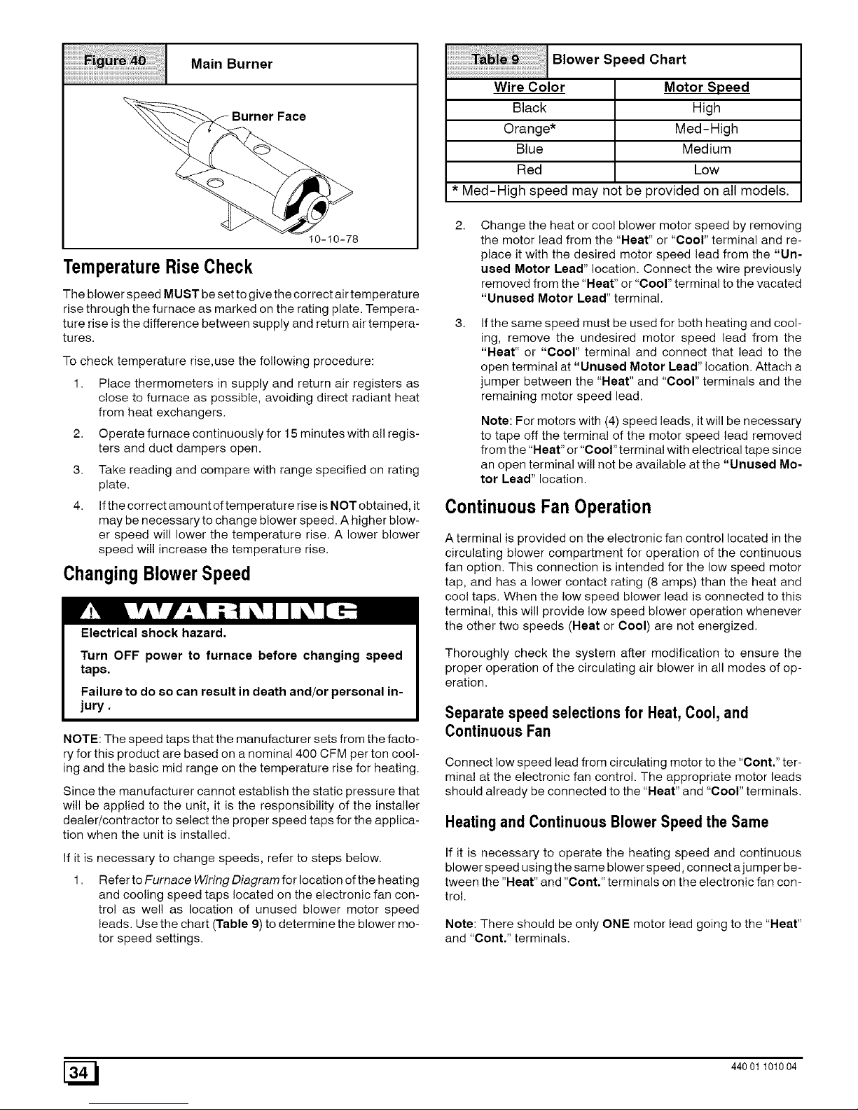
Main Burner
10-10-78
TemperatureRiseCheck
The blower speed MUST be set to give the correct air temperature
rise through the furnace as marked on the rating plate. Tempera-
ture rise is the difference between supply and return air tempera-
tures,
To check temperature rise,use the following procedure:
1. Place thermometers in supply and return air registers as
close to furnace as possible, avoiding direct radiant heat
from heat exchangers.
2. Operate furnace continuously for 15 minutes with all regis-
ters and duct dampers open.
3. Take reading and compare with range specified on rating
plate.
4. If the correct amount of temperature rise is NOT obtained, it
may be necessary to change blower speed. A higher blow-
er speed will lower the temperature rise. A lower blower
speed wil! increase the temperature rise.
ChangingBlowerSpeed
Electrical shock hazard.
Turn OFF power to furnace before changing speed
taps.
Failure to do 8o can result in death and/or personal in-
jury.
NOTE: The speed taps that the manufacturer sets from the facto-
ryfor this product are based on a nominal 400 CFM per ton cool-
ing and the basic mid range on the temperature rise for heating.
Since the manufacturer cannot establish the static pressure that
will be applied to the unit, it is the responsibility of the installer
dealer/contractor to select the proper speed taps for the applica-
tion when the unit is installed.
If it is necessary to change speeds, refer to steps below.
1. Refer to Furnace Wiring Diagram for location of the heating
and cooling speed taps located on the electronic fan con-
trol as well as location of unused blower motor speed
leads. Use the chart (Table 9) to determine the blower mo-
tor speed settings.
Blower Speed Chart
Wire Color
Black
Orange*
Blue
Red
Motor Speed
High
Med-High
Medium
Low
* Med-High speed may not be provided on all models,
Change the heat or cool blower motor speed by removing
the motor lead from the "Heat" or "Cool" terminal and re-
place it with the desired motor speed lead from the "Un-
used Motor Lead" location. Connect the wire previously
removed from the "Heat" or "Cool" terminal to the vacated
"Unused Motor Lead" terminal.
If the same speed must be used for both heating and cool-
ing, remove the undesired motor speed lead from the
"Heat" or "Cool" terminal and connect that lead to the
open terminal at "Unused Motor Lead" location. Attach a
jumper between the "Heat" and "Cool" terminals and the
remaining motor speed lead.
Note: For motors with (4) speed leads, it will be necessary
to tape off the terminal of the motor speed lead removed
from the "Neat" or "Cool" terminal with electrical tape since
an open terminal will not be available atthe "Unused Mo-
tor Lead" location.
ContinuousFan Operation
A terminal is provided on the electronic fan control located in the
circulating blower compartment for operation of the continuous
fan option. This connection is intended for the low speed motor
tap, and has a lower contact rating (8 amps) than the heat and
cool taps. When the low speed blower lead is connected to this
terminal, this will provide low speed blower operation whenever
the other two speeds (Heat or Cool) are not energized.
Thoroughly check the system after modification to ensure the
proper operation of the circulating air blower in all modes of op-
eration.
Separate speed selections for Heat,Cool, and
Continuous Fan
Connect low speed lead from circulating motor to the "Cont." ter-
minal at the electronic fan control. The appropriate motor leads
should already be connected to the "Heat" and "Cool" terminals.
Heatingand ContinuousBlowerSpeed the Same
If it is necessary to operate the heating speed and continuous
blower speed using the same blower speed, connect a jumper be-
tween the "Heat" and "Cont." terminals on the electronic fan con-
trol.
Note: There should be only ONE motor lead going to the "Heat"
and Cont.' terminals.
[_ 44001 101004
Page 35

9. Furnace Maintenance
CAUTION
It is recommended that the furnace be inspected and
serviced on an annual basis (before the heating
season) by a qualified service technician.
See "User's Information Manual" and the "Service
Manual".
10. Sequence of Operation & Diagnostics
The following is the normal operating sequence for the control system.
Cooling(Y) Request:
24 VAC signals applied to Y & G terminals of EFT (electronic fan timer) control.
• Cool motor speed energized after 6 second Coo! Fan On Delay time.
Y & G signals removed from EFT.
• Cool motor speed de-energized after 60 second Coo! Fan Oft Delay time.
CirculatingFan (G) Request:
24 VAC signals applied to G terminals of EFT control.
• Heat motor speed energized without delay.
G signal removed from EFT.
• Heat motor speed de-energized without delay.
Heating(W) Request:
24 VAC signals applied to W terminal of EFT control.
• Inducer motor turns on.
• The gas valve solenoid energizes.
• Following a 3 second prepurge delay, the pilot valve opens and the ignitor begins to warm up.
• After the pilot lights, the main burners energize and light.
• Timed from the opening of the main gas valve, the control wil! delay 30 seconds before switching the fan to Heat speed.
W signal removed from EFT.
• The gas valve de-energizes and the main burners go out.
• The inducer runs at its present speed for a 30 second postpurge period.
• Timed from the gas valve de-energizing, the Heat fan speed de-energizes after the selected Heat Fan Delay time expires.
Heating Requestwith Gas Supply LineShut Off:
24 VAC signals applied to W terminal of EFT control.
• Inducer motor turns on.
• The gas valve solenoid energizes.
• Following a 3 second prepurge delay, the pilot valve opens and the ignitor begins to warm up.
• The ignitor glows red-hot for 30 seconds, then turns off.
• The igniter stays oft for 25 seconds, then begins to warm-up again.
• The igniter glows red-hot for 30 seconds, then turns off.
• The pilot valve closes 3 seconds after the igniter de-energizes.
• The inducer de-energizes 5 seconds after the pilot valve closes.
• The SmartValve proceeds to soft lockout and flashes error code 6.
• The control exits soft lockout after 5 minutes and begins
another ignition sequence.
44001 101004 [_
Page 36

GasValveDiagnosticCodes(SeeFigure41)
OFF = Control not powered
Heartbeat = Normal Operation (Standby or call for heat)
1 Flash = Not used
2 Flashes = Pressure switch closed when should be open
3 Flashes = Pressure switch circuit was still sensed as open 30 seconds after the inducer was energized. System is
in 5 minute delay mode, with inducer off. After 5-minute delay, a new ignition sequence will be initiated.
(Note: SV9541M On/Oft switch in off position during a call for heat will generate this diagnostic code)
4 Flashes = Limit switch string open
5 Flashes = Flame sensed out of sequence - Flame signal still present.
6 Flashes + 1 Note 1 = Soft Lockout -Maximum retry count exceeded (failed to light within 4 trials for ignition)
6 Flashes + 2 Notes 1,2 = Soft Lockout -Maximum recycle count exceeded - Last failure was Flame Sense Lost During Run
6 Flashes + 3 Notes 1,2 = Soft Lockout -Maximum recycle count exceeded - Last failure was Airflow Proving Circuit Opened
During Run
6 Flashes + 4 Notes 1,2 = Soft Lockout -Maximum recycle count exceeded - Last failure was Limit Circuit Opened During Run
7 Flashes = Soft Lockout Due to Limit Trips Taking Longer than 2 minutes to Reset; Auto Reset After 1 Hour if
Call for Heat Still Present. Reset by Cycling Call for Heat at Any Time.
NOTE 1 :The 6 + X designation indicates a combination of flash codes: 6 flashes shows the control is in soft lockout, followed by X flashes
to indicate the reason the control went into soft lockout. When the 6+ X code is flashing, the SV9541 will attempt a new ignition sequence
after a five minute delay period, if the call for heat is still present. Reset of the thermostat wil! initiate a new ignition sequence immediately.
NOTE 2: Any combination of 5 'abnormal' events during a single call for heat will result in soft lockout. An 'abnormal' event is a Flame
Sense Failure During Run, Airflow Proving Circuit Open During Run, or Limit Circuit Open During Run. The flash code wil! indicate which
was the last 'abnormal' event that put the system into the soft lockout state based on the table above.
Typical Gas Valve Honeywell
OUTLET
PiIot Pressure
Adjustment
(Hidden)_
On\Off
Switch
INLET
Diagnostic Light
Manifold Pressure
Adjustment
dwg 25-23-31a
[_ 44001 101004
Page 37

HONEYWELL SV9541M "SMART VALVE" Sequence of Operation
POWER APPLIED TO APPLIANCE
i
THERMOSTAT CALLS FOR HEAT
¢
PRESSURE SWITCHES PROVED OPEN?
COMBUSTION BLOWER ENERGIZED
PRESSURE SWITCHES CLOSED WITHIN
30 SECONDS?
i
I 3 SECOND PRE-PURGE
I
PILOT VALVE OPENS:
IGNITOR POWERED (1)
i
PILOT LIGHTS AND FLAME IS SENSED
DURING 90 SECOND TRAIL FOR
IGNITION?
YES
MAIN VALVE OPENS,
HEATING FAN "ON" DELAY BEGINS
AFTER DELAY: CIRCULATING BLOWER
STARTS
FLAME SENSE LOST?
I
THERMOSTAT CALL FOR HEAT ENDS
_ NO
PILOT AND MAIN VALVE CLOSE
COMBUSTION BLOWER DE-ENER-
GIZED AFTER 30 SECOND POST PURGE
CIRCULATING BLOWER OFF AFTER
DELAY
V
I
WA,TFORPRESSURESW,TOHESTOOPENI
COMBUSTION BLOWER DE-ENERGIZED
FIVEMINUTEWAITPERIOD
I
THREE SECOND FLAME [_
FAILURE RECYCLE DELAY
YES
I
PILOTVALVECLOSES;
PILOTIGNITOROFF
PILOT AND MAIN VALVE CLOSE
V
FLAME SENSE LOST MORE THAN FIVE |
TIMES INTHIS CALL FOR HEAT?
YES
r
CIRCULATING BLOWER OFF AFTER
DELAY
COMBUSTION AIR BLOWER OFF AFTER
POST PURGE
WAIT FOR NEXT CALL FOR HEAT I
(1) Ignitor "ON" for first 30 seconds oftrial for ignition, then "OFF" for next 30 sec-
onds. If the pilot has not lit, itturns back "ON" for the final 30 seconds. The pilot
valve remains energized during the entire 90 second trial for ignition.
NOTE: If main limit string opens and takes longer than 2 minutes to close, system
goes into 1 hour wait period.
44001 101004 [_
Page 38

HONEYWELL SV9541M "SMART VALVE" Trouble shooting
The 6 + X designation indicates a combination of flash codes: 6 flashes shows the control is in soft lockout, followed by X flashes to
indicate the reason the control went into soft lockout. Last status code indicates repair to address first
LED
INDICATES CHECK/REPAIR
STATUS
Line voltage input at L1 and Neutral connectors on ST9160B Fan Timer.
Off No power to system control. Low voltage (24V) power at 24 VAC and COM terminals on ST9160B
System wiring harness is in good condition and securely connected.
Heartbeat Normal indication whenever the system is powered, unless some
Bright - Dim abnormal event has occurred. Not Applicable - Normal Operation (stand by or call for heat)
Pressure switches closed when itshould be open Pressure switches stuck closed (system will wait for pressure switch to
(i.e. when call for heat begins).
2 Flashes open).
(Combustion blower is not energized until pressure switches
opens) Pressure switches miswired orjumpered.
Pressure switches, open when they should be closed (i.e.longer
than 30 seconds after combustion blower!inducer is energized).
3 Flashes
4 Flashes
5 Flashes
6 Flashes +
1 Flash
6 Flashes +
2 Flashes
System goes into 5-minute delay period, with combustion blower/
inducer off. At end of the 5-minute delay, another cyclewill begin.
Main Umit or Roll Out Switch is open.
Combustion blower is energized, Circulating blower is energized
heat speed.
Flame signal sensed out of proper sequence.
Combustion blower is energized, Circulating blower is energized
heat speed after the "ON" delay.
Soft Lockout.
Failed to light pilot during 90 sec. trial for ignition
Combustion air blower is de-energized, Circulating blower is de-
energized after the "OFF" delay.
After 5-minute delay time, control system will reset and initiate a
new ignition sequence,
SoftLockout.
Last failure was Flame Sense lost during run.
Maximum recycle count exceeded
Combustion air blower is de-energized, Circulating blower is
de-energized after the "OFF" delay.
After 5-minute delay time, control system will reset and initiate a
new ignition sequence,
Ignition system control switch must be in the ON position.
Pressure switches operation, tubing, and wiring.
Restrictions in furnace air intake or vent piping.
Main limit switch.
Manual reset burner rollout switch.
Limit and rollout switch wiring is in good condition and securely
connected.
Flame at pilot burner.
Gas supply off or pressure too low or high for appliance to operate.
Damaged or broken HIS element
Line voltage HOT lead wire not connected to L1 terminal on ST9160B.
Furnace not properly earth grounded.
Flame sense rod contaminated or in incorrect position.
Pilot burner located in incorrect position.
Pilot burner lead wires are in good condition and popery connected.
Pressure switches operation, tubing, and wiring.
Gas supply off or pressure too low or high for appliance to operate.
Line voltage HOT lead wire not connected to L1 terminal on ST9160B.
Furnace not properly earth grounded.
Flame sense rod contaminated or in incorrect position.
Pilot burner located in incorrect position.
Pilot burner lead wires are in good condition and properly connected.
Cycling, pressure switch
Condensate drain blocked
Pressure switches operation, tubing, and wiring.
[_ 44001 101004
Page 39

HONEYWELL SV9541M "SMART VALVE" Trouble shooting continued
LED
INDICATES CHECK/REPAIR
STATUS
SoftLockout.
6 Flashes +
3 Flashes
6 Flashes +
4 Flashes
7 Flashes
Last failure was pressure switch
Maximum recycle count exceeded
Combustion air blower is de-energized, Circulating blower is de-
energized after the "OFF" delay.
After 5-minute delay time, control system will reset and initiate a
new ignition sequence,
Soft Lockout.
Lastfailurewaslimitcircuitopenedduringrun.
Combustion air blower is de-energized, Circulating blower is
de-energized after the "OFF" delay.
After5-minute delaytime,controlsystemwillresetandinitiatea
newignitionsequence,
Soft Lockout.
Blowerfailure(typical)
Limittrip tooklongerthan2 minutesto reset.
Systemwillstarta newignitionsequenceafter1 hour,if callfor
heatstill present.
Ignitionsystemcontrolswitchmustbein theONposition.
Pressureswitchesoperation,tubing,andwiring.
Restrictionsinfurnaceairintakeorventpiping.
Highwindsblowingagainstvent.
Mainlimitswitch.
Limitand rolloutswitchwiringisin goodconditionandsecurely
connected.
Restrictioninduct work.
Dirtyfilter
Deadblower.
Blockedductwork.
44001 101004 [_
Page 40

11. Concentric Termination
VentTermination Clearances
Poison carbon monoxide gas, fire and explo-
sion hazard.
Inlet and outlet pipes may NOT be vented
directly above each other (standard vent
terminals).
Failure to properly vent this furnace can result in
death, personal injury and/or property damage.
1. Determinetermination locations based on clearances spe-
cified in following steps and as shown in Figure 7,
Figure 42 through Figure 47,
2. The vent termination must be located at least 12" above
ground or normally expected snow accumulation levels.
Do NOT terminate over public walkways. Avoid areas
where condensate may cause problems such as above
planters, patios, or adjacent to windows where steam may
cause fogging.
The venttermination shall be located at least 4' horizontally
from any electric meter, gas meter, gas regulator, and any
relief equipment. These distances apply ONLY to U.S.
installations.
The vent termination is to be located at least 3' above any
forced air inlet located within 10' ; and at least 10' from a
combustion air intake of another appliance, except another
direct vent furnace intake.
6. In Canada, the Canadian Fuel Gas Code takes prece-
dence over the preceding termination instructions.
ConcentricVentTermination- Kit#
NAHA001CV& NAHA002CV
These kits are for vertical or horizontal termination of the combus-
tion air inlet and the exhaust vent pipes on Category iV gas-fired
condensing furnaces. The NAHA001CV kit can be used for 3" di-
ameter pipe systems. The NAHA002CV kit can be used for 2"
diameter pipe system. Refer to Table 10 for the correct pipe size
for the furnace. Both the combustion air inlet and the exhaust vent
pipes must attach to the termination kit. The termination kit must
terminate outside the structure and must be installed per the
instructions outlined below for vertical or horizontal termination.
Vertical termination is preferred. Field supplied pipe and fittings
are required to complete the installation.
Kit Contents:
Kit Components
3" Rain Cap or 2" Rain Cap
3" Diameter SDR-26 Pipe, 191/2" Long or
4" Diameter SDR-26 Pipe, 371/8" Long,
2" Diameter SDR-26 Pipe, 315/8" Long or
21/2" Diameter SDR-26 Pipe, 24" Long,
3" Y Concentric Fitting or 2" Y Concentric Fitting
3" or 4" Dia.
SDR-26 Pipe
2" or 3" Dia. 2 or 21/2" Dia.
Y Concentric Fitting SDR-26 Pipe
2" or 3" Dia.
Rain Cap
25-22-03
Vertical& Horizontal Termination
1.
2.
Determine the pipe diameters required for the installation
from Table 10 and Figure 44.
Determine the best location for the termination kit. See
Figure 43 for vertical termination or Figure43 and
Figure 47 for horizontal termination. Roof termination is
preferred since it is less susceptible to damage, has re-
duced intake contaminants and less visible vent vapor. For
side wall termination, consideration should be given to: 1)
possible damage from the vapors to plants/shrubs, other
equipment and building materials, 2) possible damage to
the terminal from foreign objects, 3) wind effects that may
cause recirculation of flue products, debris or light snow
and 4) visible vent vapor.
Concentric Vent Roof Installation
Vent!_ Maintain 12" rain. clearance
U
above highest anticipated
snow level. Max. of 24"
above roof.
Combustion
Air
Roof Boot/
Flashing
(Field
Support
(Field Supplied)
j45 Elbow
(Field Supplied)
Vent
Combustion
Air 25-22-02
Note:
Support must be field installed to secure termination kitto structure.
3. Cut one 5" diameter hole through the structure for the
NAHA001CV Kit or one 4" diameter hole for the
NAHA002CV Kit.
[_ 44001 101004
Page 41

4.DimensionDmaybelengthenedto60"max.orshortenedby
cuttingthepipesto12"min.DimensionAwillchangeaccord-
ingtoDdimension.(SeeFigure44)
ConcentricVentDimensional
...........................................................................Drawing
B PVC
Vent/Exhaust
11/2"-- : _
PVC Intake/Combustion Air
A -_
25-22-03
Model A* B C D**
NAHA001CV 387/8 3 41/2 211/8
NAHA002CV 333/8 2 31/2 167/8
* = Dimension will change accordingly as dimension D is
lengthened or shortened.
**= Dimension D may be lengthened to 60" may also be
shortened by cutting the pipes provided in the kit to 12"
minimum
Concentric Termination Kit
Ta_i_ _ NAHA001 CV & NAHA002CV Venting
Table Dual Piping ONLY
50,000 & 75,000 Btuh Furnaces
NAHA002CV - 35' & (4) 90 ° elbows with 2" PVC pipe
NAHA001CV - 65' & (4) 90 ° elbows with 3" PVC pipe
100,000 Btuh Furnace
NAHA001CV - 65' & (4) 90 ° elbows with 3" PVC pipe
125,000 Btuh Furnace
NAHA001CV - 35' & (4) 90 ° elbows with 3" PVC pipe
1. Do not include the field supplied 45 °elbow in the total elbow
count.
2. If more than four elbows are required, reduce the length of
both the inlet and the exhaust pipes five feet for each
additional elbow used.
3. Elbows are DWV long radius type for 2" and 3" vents.
If more than four elbows are required, reduce the length of
both the inlet and exhaust pipes 5' for each additional elbow
used.
* Feet of pipe iswhichever pipe run is the longest, either inlet
or outlet side.
If assembly needs to be extended to meet height or side wall
thickness requirement, the two pipes supplied in the kit may be
replaced by using the same diameter solid, single (no coupling
connections) field supplied SDR-26 PVC (ASTM D2241) pipes.
Do not extend dimension D more than 60". (See Figure 44)
Do not use field supplied couplings to extend the
pipes. Airflow restriction will occur and the furnace
pressure switch may cause intermittent operation.
Partially assemble the concentric vent termination kit.
Clean and cement the parts using the procedures for Join-
ing Pipe and Fittings section of the manual. A) Cement the
Y Concentric fitting to the 4" diameter kit pipe. (See
Figure 45) B) Cement the 3" rain cap to the 21/2" diameter
kit part. (See Figure 45) NOTE: A field supplied stainless
steel screw may be used to secure the rain cap to the pipe
instead of cementing when field disassembly is desired for
cleaning (See Figure 45)
iiiiiiiiiiii_ii_i!i_i_i_i;i;!ii!iiiiiiiii_i_i_!_i_iii;il_;i;i_i_i_i_i!i_ii_ii_ii_i_i_i_i!i_!i_i_i_i_i_i_i_ii_ii_i_ii_i_i_i_i_i_i_i_i_i_i_
;i
25-22-02
Rain Cap to Vent Pipe Assembly
Drill clearance hole in rain
cap and pilot hole in vent pipe.
Stainless steel screw
(Field supplied)
Poison carbon monoxide gas hazard.
When using the alternate screw assembly
method, drill a clearance hole in the rain cap and
a pilot hole in the vent pipe for the screw size
being used. Failure to drill adequate holes may
cause cracking of the PVC components,
allowing flue gases to be recirculated.
Failure to follow this warning could result in
death, personal injury and/or property damage.
Poison carbon monoxide gas hazard.
Do not operate the furnace with the rain cap
removed as recirulation of the flue gases may
occur. Water may also collect inside the larger
combustion air pipe and flow to the burner
enclosure.
Failure to follow this warning could result in
death, personal injury and/or property damage.
Install the Y concentric fitting and the pipe assembly
through the structure's hole. For vertical termination, install
the parts through the field supplied roof boot/flashing.
NOTE: Do not allow insulation or other materials to accu-
mulate inside the pipe assembly when installing through
the structure's hole.
Secure the assembly to the structure as shown in
Figure 43 or Figure 47 using field supplied metal strap-
ping or equivalent material.
NOTE: Ensure the termination height is above the roof sur-
face or anticipated snow level as shown in Figure 43 for
vertical termination. Ensure the termination location clear-
ancedimensions areas shown in Figure 46and Figure 47
for horizontal termination.
44001 101004 E_
Page 42
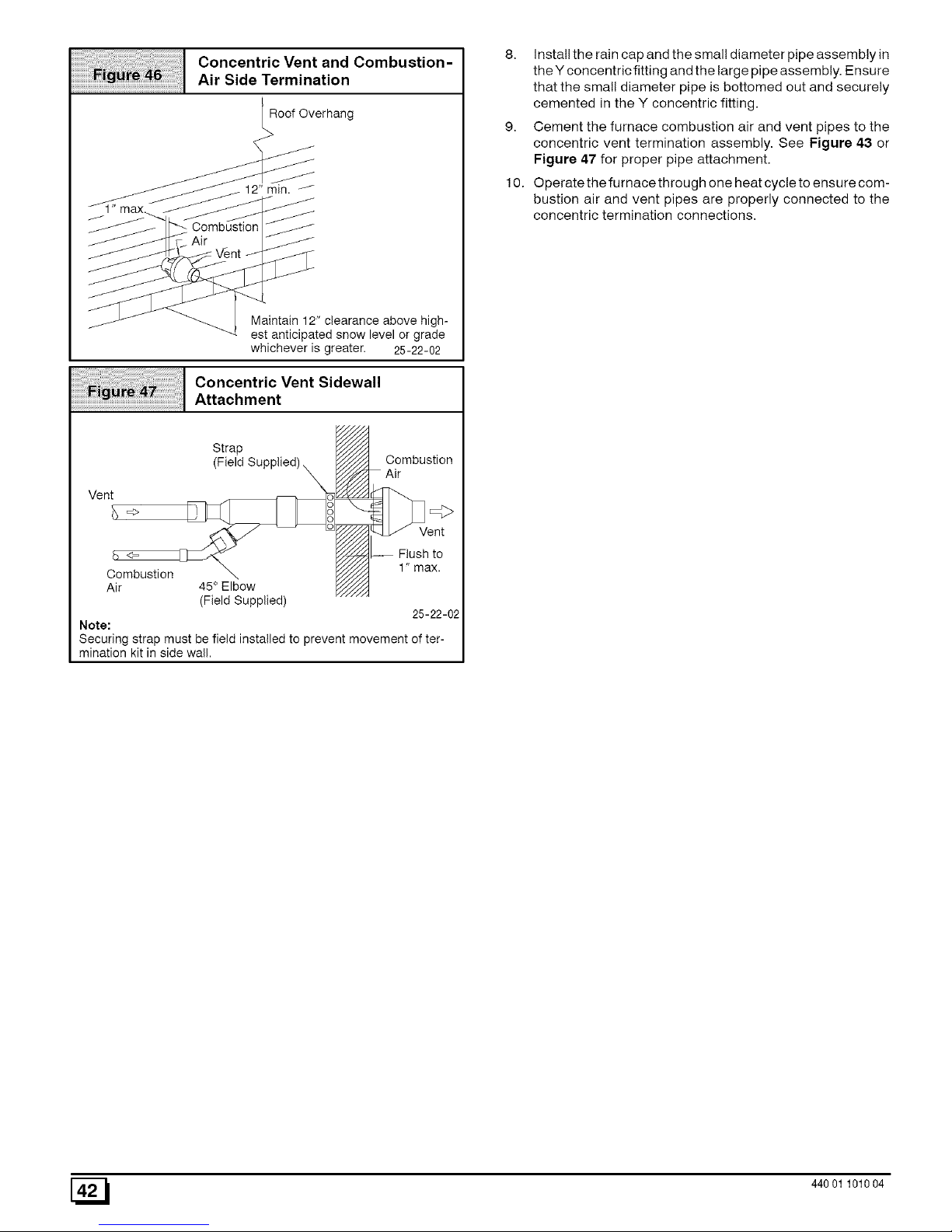
iiiiiiiiiiii_ii_i!i_i_i_;i;!!i!iii_iiiiiiiii_i_iii_;!_il!i_iiiiii_iii_iiilii_ii_i_!_!i!i!i!_i_iiiii!!_!_i!_i_i_i_i_iiiiiiiii_i_i_i_iiii_i_i_i_i_i_i_i_i
ConcentricVentand Combustion-
...........................................................................Air Side Termination
Roof Overhang
_1" max
iiili;iiiillliiliill_i_ililllllli;liliiiiiiiiillillllllllllllllillllliilililllllllllllll
Maintain 12" clearance above high-
est anticipated snow level or grade
whichever is greater. 25-22-02
Concentric Vent Sidewall
Attachment
Strap
(Field Supplied) X
Vent
Combustion
Air 45 ° Elbow
(Field Supplied)
Combustion
Air
ent
_d..-¢d_..-- Flush to
;;;;;; 1"max.
25-22-02
Note:
Securing strap must be field installed to prevent movement of ter-
mination kit in side wall.
8. Install the rain cap and the small diameter pipe assembly in
the Y concentric fitting and the large pipe assembly. Ensure
that the small diameter pipe is bottomed out and securely
cemented in the Y concentric fitting,
9. Cement the furnace combustion air and vent pipes to the
concentric vent termination assembly. See Figure 43 or
Figure 47 for proper pipe attachment.
10. Operate the furnace through one heat cycle to ensure com-
bustion air and vent pipes are properly connected to the
concentric termination connections.
[_ 44001 101004
 Loading...