

High
MAIC
Efficiency Air Cleaner
Manual for:
Installation • Operation •
i
Maintenance
MAIC0014A & MAIC0020A
Literature # 616 01 1004 02 1.o7
NOTE: Read the entire instruction manual before starting the installation.
SAFETY CONSIDERATIONS
Installation and service of heating and air conditioning equipment can be
hazardous due to system pressure and gas and electrical components. Only
trained and qualified personnel should repair, or service heating and air
conditioning equipment. Untrained personnel can perform basic maintenance
functions such as cleaning and replacing air filters. All other operations must be
performed by trained service personnel. When working on heating and air
conditioning equipment, observe precautions in the literature, tags, and labels
attached to or shipped with the unit and other safety precautions that may apply.
Follow all safety codes. Wear safety glasses and work gloves. Use quenching cloth
for brazing operations. Have fire extinguisher available. Read these instructions
thoroughly and follow all warning or cautions attached to the unit. Consult local
building codes and National Electrical Code (NEC) for special requirements. It is
important to recognize safety information.
DANGER, WARNING, CAUTION and NOTE
The signal words DANGER, WARNING, CAUTION, and NOTE are used to identify
levels of hazard seriousness. The signal word DANGER is only used on product labels
to signify an immediate hazard. The signal word WARNING, CAUTION and NOTE will
be used on product labels and throughout this manual and other manuals that may
apply to the product.
DANGER -
WARNING -
CAUTION -
NOTE -
Immediate hazards which will result in severe personal injury or death.
Hazards or unsafe practice which could result in severe personal injury
or death.
Hazards or unsafe practices which may result in minor personal injury or
product or property damage.
Used to highlight suggestions which will result in enhanced installation,
reliability, or operation.
Signal Words in Manuals
The signal word WARNING is used throughout this manual in the following manner:
The signal word CAUTION is used throughout this manual in the following manner:
Signal Words on Product Labeling
Signal words are used in combination with colors and/or pictures on product labels
iNTRODUCTiON
The Model MAIC High Efficiency Air Cleaner isdesigned for installationinthe return=
air duct in any forced-air heating and/or cooling system. The model MAIC High
Efficiency Air Cleaners are available in two sizes, 0014 and 0020.
The FMC media filter isa mechanical air cleaner incorporating special pleated filter
media designed to remove dirt, dust, pollen, and other microscopic particles from
the air passing through it.The pleats provide an exceptionally filtering face area in a
very compact space which allows maximum dirt holding capacities.
When applying the MAIC, attention must be given to duct and system design
because these components affect system static pressure. To maintain the proper
efficiency and reliable operation of the MAIC Mechanical Air Cleaner and your
HVAC equipment, this filter should only be applied to properly designed duct
systems and properly sized HVAC equipment. The MAIC has a higher static
pressure drop than the typical factory supplied furnace and/or fan coil filter (See
Typical Pressure Drop Table).
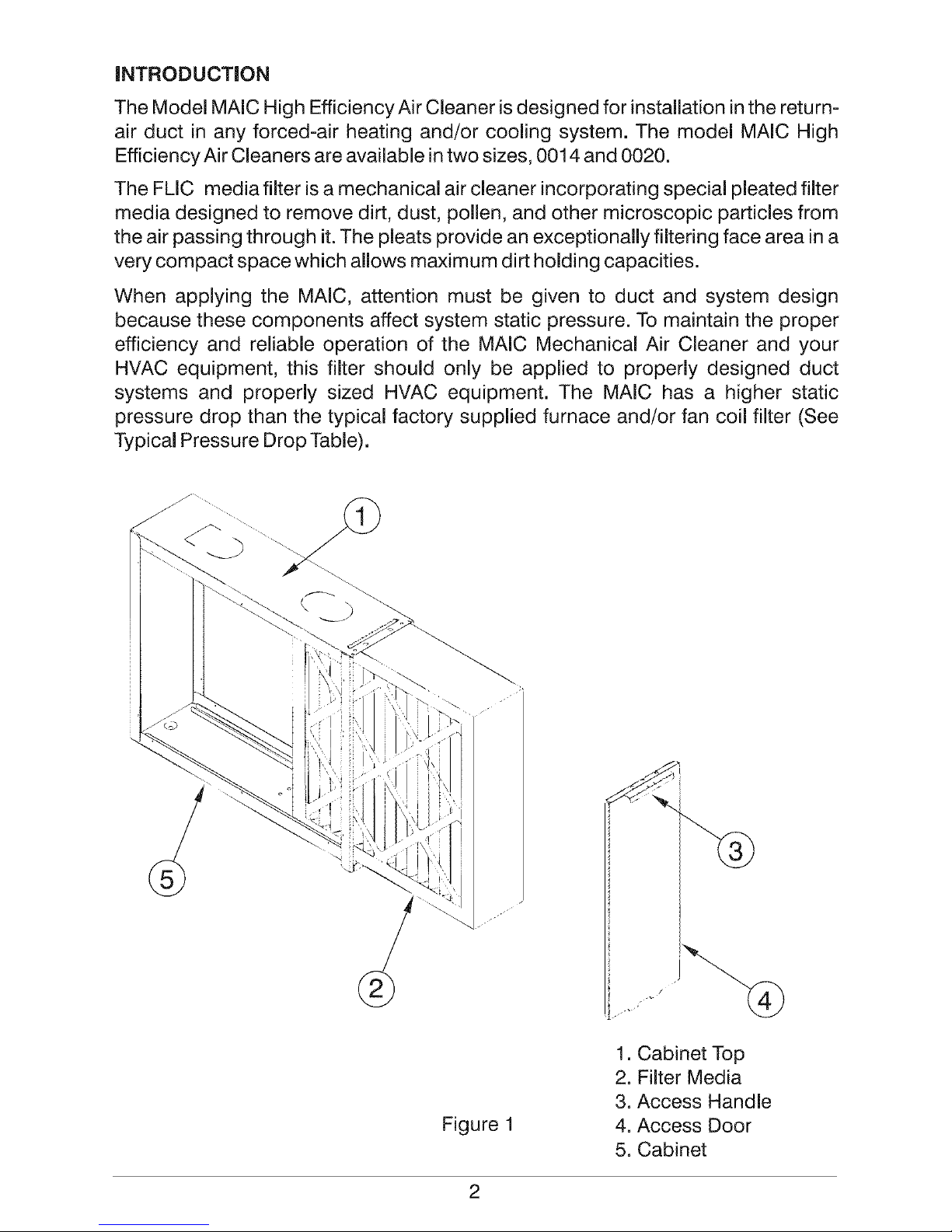
Figure 1
1. Cabinet Top
2. Filter Media
3. Access Handle
4. Access Door
5. Cabinet
2
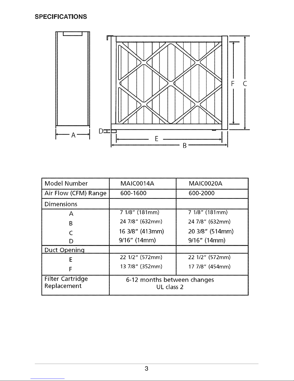
SPECiFiCATiONS
=== A ===_
r
D=T=
=1
\% I I I Y/fl _ [ I I 7/
"N"xl I 1,".,€ I I "_\1 [ k"/I
I "_N_.../A I I I I "N'_t,'71 I
I .Y/T'%_II I I I I Y/-N"',,I I
\_ I I J Yiq N_M I I I i'_"
"b.".,l I _'/f I I \",,,l I )/_
I I//TN'M I I I I J//qN",d I
/A I I I "N_I ],//I I I I \_
B
F C
!!
Model Number
Air Flow (CFM) Range
Dimensions
A
B
C
D
Duct Openinq
E
F
Filter Cartridge
Replacement
MAIC0014A MAIC0020A
600-1600 600-2000
7 1/8" (181mm)
24 7/8" (632mm)
16 3/8" (413mm)
9/16" (14mm)
7 1/8" (181mm)
24 7/8" (632mm)
20 3/8" (514mm)
9/16" (14mm)
22 1/2" (572mm) 22 1/2" (572mm)
13 7/8" (352mm) 17 7/8" (454mm)
6-12 months between changes
UL class 2
3

AiR FLOW RESISTANCE
Typical Pressure Drop
Mode! Number
Air Flow (CFM) MAIC0014A MAIC0020A
Resistance (in. w.c.)
600
800
1000
1200
1400
1600
1800
2000
.04 .03
.07 .04
.10 .06
.14 .08
.18 .11
.23 .13
== .17
== .18
4

TYPICAL MOUNTING POSiTiONS
MEDIA
AIR CLEANER
BASEMENT FURNACE
(LOWBOY)
Mounted horizontally in return
plenum -just above the furnace
COUNTERFLOW FURNACE
Mounted horizontally in return
duct - just above the furnace
OFFSET INSTALLATION
If there is less than 7-in. for mounting the air cleaner
between the duct and the furnace, move the return air drop.
SHEET METAL
TRANSITIONS _ I
MEDIA /
AIR CLEANER
BLOWER
/
SPACE SAVER FURNACE
(HIGHBOY)
Side installation. Cleaner is
mounted vertically, where
return air enters side inlet of
furnace.
SPACE SAVER (HIGHBOY)
Installation beneath furnace. Cleaner
mounts horizontally, where return air
enters from below. Raise furnace by
installing a suitable wood structure and
install air cleaner.
HORIZONTAL FURNACE
Mounted vertically in return duct as close to
the furnace as possible
5

APPLiCATiON
The air cleaners are used in forced air heating, cooling and ventilating
systems. The air cleaner should be installed in the system so that all the
system air is circulated through the air cleaner. The air cleaner will only
remove the airborne contaminants delivered to it. Maximum performance
isobtained when the system blower is set for continuous operation.
Installation Requirements
The best location for the air cleaner is in the return air duct next to the
blower compartment. In this location, the blower motor and cooling coils
will be kept clean. Do not install the air cleaner in the discharge air duct.
Before installing the air cleaner, consider the application. If a transition is
required, refer to section entitled Transitions. The unit must be readily
accessible for periodic inspection and replacement of media cartridge to
maintain maximum efficiency and trouble-free operation.
Air Conditioning.
The air cleaner should be installed upstream of the cooling coil. This will
keep the coil clean and reduce air conditioning coil maintenance.
improved cooling efficiency is the result which directly affects energy
costs. A clean coil will reduce utility costs. Failure to replace media can
cause damage to cooling system.
Transitions
if the air duct does not fit the air cleaner cabinet opening, gradual
transitions are recommended to reduce air turbulence through the air
cleaner and maximize efficiency. Not more than 20° (about 4" per running
foot) of expansion should be used on each side of the transition fitting
(Figure 2). M_imurn4,,Drop
Per Uneal Foot
Air FIo )
Air Clea_i_
Operlir_g A_c E_N.
Air Cleaner
Transition Section
<2>
Air Flow
E:_
\ Furnace
Opening
Furnace
Figure 2 - Transitions
6

Turning Vanes
Ifthe air cleaner is installed adjacent to a 90°duct elbow, add turning vanes
inside the duct to improve the air distribution across the face of the air
cleaner (Figure 3).
J
Figure 3 - Turning Vanes
Humidifiers
Location of the system humidifier is important to the operation of the
air cleaner.When an evaporative type humidifier is used, it may be
installed between the furnace warm air duct and the return air duct
without effecting the air cleaner.Atomizing and spray humidifiers
should be installed downstream of the air cleaner. If the humidifier
must be installed upstream, allow at least 6 feet between the
air cleaner and humidifier.
7

SELECT LOCATION FOR THE AiR CLEANER
Select a location that is readily accessible for periodic inspection and
cleaning. Allow a minimum of 26" in front of the access panel for filter
removal. For complete dimensions required, refer to the section entitled
SPECiFiCATiONS.
DiRECTiON OF AiR FLOW THROUGH THE AiR CLEANER
The air cleaner isset up for left to right air flow, when facing the access
door. For right to left air flow remove filter cartridge, turn it around and
replace in cabinet. The directional arrows on the filter cartridge must
point in the direction of air flow.
PHYSICAL iNSTALLATiON
The air cleaner can be in any position, except with the access door
facing down. The section entitled TYPICAL MOUNTING POSiTiONS
(page 5) shows proper air cleaner mounting with a variety of furnace
installations.
CUT HAZARD
Failure to follow this caution may
result in personal injury.
Sheet metal parts may have sharp
edges or burrs. Use care and wear
appropriate clothing, safety
glasses and gloves when handling
parts and servicing equipment.
ELECTRIC SHOCK HAZARD
Failure to follow this caution may
result in personal injury or death.
Before installing, modifying or
servicing system, turn OFF the
main (remote electrical disconnect
device. There may be more than
one disconnect device.
Prior to installing this product...
1. Check the ratings given on the product to make sure it is suitable for
your application.
2. Remove the old furnace filter and discard.
3. The air cleaner cannot remove existing dirt from the blower and
ducts.
8

NOTE:
Thefollowingis a typical installation of the air cleaner on a high boy
furnace. You may have to alter the installation to fit your specific
application.
5. Locate the cabinet in the cold air return duct so that all of the return
air flows through the unit. If the furnace and air cleaner openings are
different, use atransition (see Figure 2).
6. Mounting holes are provided for
simple connection to duct work.
The .140" holes are sized for #8
sheet metal screws, or 1/8" rivets. If
the adjoining duct work is flanged,
install the screws so that the screw
heads are inside the cabinet. This
will prevent damage to the filter
cartridge during removal and
installation (Figure 4).
7. Remove media filter cartridge from
plastic bag and replace media
filter in cabinet.
Figure 4
m
Screw
I
I
q
J
8. After the unit has been secured, seal seams air tight with duct tape
or caulking. Reinstall access door to ensure atight seal.
9

HOW TO MAINTAIN YOUR AIR CLEANER
The filter in your air cleaner must be replaced periodically. The frequency
of filter replacement is best determined by visual examination. On
average, media filters should be replaced every 6-12 months under
normal usage.
STEPS FOR REPLACING FILTER
1. Open access door by pulling the handle. Remove door completely.
2, Pull used filter straight out of cabinet and disassemble and discard
3, Remove new filter cartridge from box and assemble,.
4, Slide new filter cartridge into cabinet with "AIR-FLOW" arrow pointing in
the direction of air flow.
5. Replace door.
Replacement Cartridge Filters For Your Media Air Cleaner
Remember, periodic inspection and annual replacement of your filter will
insure high efficiency air cleaning. Contact your HVAC dealer for
replacement filter cartridges.
Order Number
Quantity per Carton
Replacement Filters
FLICO014A
2
FLICOO20A
2
10

Five=Year Limited Cabinet Warranty =
This product is warranted to be free from defects in material and workmanship for a period of
five years from the date of original installation, whether actual use begins then or later, If the
product fails during the warranty period, a new or remanufactured part, at the manufacturer's
sole option, will be provided to replace any defective part without charge for the part itself;
PROVIDED the defective part isreturned to the distributor through a qualified servicing dealer,
This warranty does not include or cover labor or other costs- incurred for diagnosing, repairing,
removing, installing, shipping, servicing or handling of either defective parts or replacement
parts.
THIS WARRANTY APPLIES ONLY TO PRODUCTS IN THEIR ORIGINAL INSTALLATION LOCATION
AND BECOMES VOID UPON REINSTALLATION.
LIMITATIONS OF WARRANTIES =ALL IMPLIED WARRANTIES, INCLUDING THE IMPLIED WARRANTIES OF
MERCHANTABILITY AND OF FITNESSFORA PARTICULARPURPOSE,ARE HEREBY DISCLAIMED TO THE
FULLESTEXTENTALLOWED BY LAW. IF APPLICABLELAW PROHIBITSDISCLAIMING SUCH WARRANTIES,
THEN THEY ARE LIMITED TO THE SHORTESTPERIODALLOWED BY LAW. SOME STATESDO NOT ALLOW
DISCLAIMING OR LIMITING IMPLIED WARRANTIES SO THESE LIMITATIONS MAY NOT APPLY TO YOU.
THE EXPRESSWARRANTIES MADE IN THIS WARRANTY ARE EXCLUSIVE AND MAY NOT BE ENLARGED
OR CHANGED BY ANY PERSON.
All work under the terms of this warranty shall be performed during normal working hours. All
replacement parts, whether new or remanufactured, assume as their warranty period only the
remaining time period of this warranty.
THE MANUFACTURER WILL NOT BE RESPONSIBLEFOR:
1. Normal maintenance as outlined in the installation and servicing instructions or owners
manual including filter cleaning and/or replacement and lubrication.
2. Damage or repairs required as a consequence of faulty installation, misapplication, abuse,
improper servicing, unauthorized alteration or improper operation.
3. Failure to start due to voltage conditions, blown fuses, open circuit breakers or other
damages due to the inadequacy or interruption of electrical service.
4. Damage as a result of floods, winds, fires, lightning, accidents, corrosive environments or
other conditions beyond the control of the Manufacturen
5. Parts not supplied or designated by the Manufacturer, or damages resulting from their use.
6. Manufacturer products installed outside the continental U.S.A., Alaska, Hawaii, and Canada
7. Electricity or fuel costs or increases in electricity or fuel costs or increases in the electricity or
fuel costs from any reason whatsoever including additional or unusual use of supplemental
electric heat.
8. Any special indirect or consequential property or commercial damage of any nature
whatsoever, Some states do not allow the exclusion of incidental or consequential damages,
so the above may not apply to you.
This warranty gives you specific legal rights, and you may also have other rights which may
vary from state to state.
International Comfort Products, LLC
650 Hell Quaker Blvd., Lewisburg, TN 37091 U.S.A.
155595-009,
 Loading...