

ICP iMAT 32VBI-ELV Instructions For Installation And Operation Manual
EN-US - english US
Instructions for installation and operation
¡MAT 32VBI-ELV
Condensate drain
01-2825

Dear customer,
Thank you for deciding in favor of the iMAT 32VBI-ELV condensate drain. Please read the installation and
operating instructions carefully before mounting and starting up the iMAT 32VBI-ELV, and follow our
directions. Perfect functioning of the iMAT 32VBI-ELV, and thus reliable condensate discharge, can only be
guaranteed when the provisions and notes stipulated here are strictly adhered to.
2 iMAT 32VBI-ELV

1 Pictograms and symbols ........................................................................................................................4
2 Safety instructions ..................................................................................................................................4
3 Proper use..............................................................................................................................................6
4 Exclusion from the scope of application.................................................................................................6
5 Technical data ........................................................................................................................................7
6 Electrical data.........................................................................................................................................8
7 Dimension drawing.................................................................................................................................9
8 Function................................................................................................................................................10
9 Installation ............................................................................................................................................13
10 Electrical installation.............................................................................................................................16
11 Control and maintenance .....................................................................................................................19
12 Troubleshooting and fault elimination ..................................................................................................23
13 Elements and components...................................................................................................................24
14 Recommended spare parts..................................................................................................................24
iMAT 32VBI-ELV 3
Pictograms and symbols
Pos:1/Beko Technische Dokumentati on/Überschrift en/1/Piktogram me und Symbol e @ 1\mod_12 90773595840 _15098.docx @ 20 525 @ 1 @ 1
1 Pictograms and symbols
Pos:2/Beko Technische Dokumentati on/Piktogramm e/Anleitung b eachten blau @ 0 \mod_1213268 300255_1509 8.docx @ 15193 @ @ 1
Observe the installation and operating instructions
Pos:3/Beko Technische Dokumentati on/Piktogramm e/Anleitung b eachten s/w T ypenschild @ 1\m od_12907721801 42_15098.d ocx @ 20492 @ @ 1
Observe the installation and operating instructions
(on the type plate)
Pos:4/Beko Technische Dokumentati on/Piktogramm e/Gefahr Warn ung Vorsicht s/ w @ 0\mod_121 3265685174_ 15098.docx @ 15189@ @ 1
General danger symbol (danger, warning, caution)
Pos:5/Beko Technische Dokumentati on/Piktogramm e/G+W+V Netz spannung s/ w @ 0\mod_1213 266193701_1509 8.docx @ 15 191 @ @1
General danger symbol (danger, warning, caution) for supply voltage and supply voltagecarrying plants components
Pos:6/Beko Technische Dokumentati on/Überschrift en/1/Sicherheits hinweise @ 0\m od_118363760 9261_15098.d ocx @ 15102 @ 1 @1
2 Safety instructions
Pos:7/Beko Technische Dokumentati on/Globale T exte/Allgemeiner Hi nweis BM @ 0\ mod_118361 5737313_150 98.docx @ 1509 9@ @ 1
Pos:8/Beko Technische Dokumentati on/Sicherheit/Hi nweis Anleitu ng mit DocVar als Fir menname @8\mod_ 14050627803 58_15098.doc x@ 41099@ @ 1
Please check whether or not these instructions correspond to the device type.
Adhere to all advice given in these operating instructions. They include essential information
which must be observed during the installation, operation and maintenance. Therefore it is
imperative for the service technician and the responsible operator / technical staff to read these
operating instructions prior to installation, start-up and maintenance.
The operating instructions must be accessible at any time at the place of application of the
iMAT 32VBI-ELV.
In addition to these operating instructions, local or national regulations must be complied with,
if necessary.
Make sure that the iMAT 32VBI-ELV is operated only within the permissible limit values
indicated on the type plate. Any deviation involves a risk for persons and materials, and may
result in malfunction and service failures.
If you have any queries regarding these installation- and operating instructions, please contact
Independent Compressor Partners.
Pos:9/Beko Technische Dokumentati on/Sicherheit/ Gefahr Druc kluft @ 0\mod_11 84148143854_15 098.docx @ 15121@ @ 1
Danger!
Compressed air!
Risk of serious injury or death through contact with quickly or suddenly escaping
compressed air or through bursting plant components or plant components which are
Pos:10/Be koT echnisch eD okumentati on/Sicherheit/Maß nahmen Druc kluft BM @ 0\ mod_118414828 4291_15098. docx@ 15123 @ @1
Measures:
• Do not exceed the maximum operating pressure (see type plate).
• Only carry out service measures when the system is pressure less.
• Use pressure-resistant installation material only.
• The feed pipe must be tubed firmly. Discharge pipe: short, fixed pressure hose onto pressure-resistant
pipe.
• Make sure that persons or objects cannot be hit by condensate or escaping compressed air.
not secured.
Pos:11/Be koT echnisch eD okumentati on/Sicherheit/Gef ahr Netzspan nung 1 s/w @ 0\ mod_118414 8186948_15098.d ocx @ 15122 @ @ 1
4 iMAT 32VBI-ELV
Safety instructions
Danger!
Supply voltage!
There is the risk of an electric shock involving injury or death when coming into contact
Pos:12/Be koT echnisch eD okumentati on/Sicherheit/Maß nahmen Netzs pannung BM 31U/ 32U/33U @ 7\mod_1390467197804_ 15098.docx @ 3 8070 @ @1
Measures:
• During electric installations, all regulations in force need to be adhered to (e.g. VDE 0100 / IEC 60364).
• When the control unit is open, service and installation works must only be undertaken when the
system is deactivated.
• The removed control unit has no IP degree of protection.
• All types of electrical works must be carried out by authorized and qualified personnel only.
Pos:13/Be koT echnisch eD okumentati on/Sicherheit/Sich erheitshinweis e, weitere BM ( nicht Ex, nic htIF ) @ 0\mod_118 3616103770_ 15098.docx @ 15100@ @ 1
Further safety instructions:
• For installation and operation, the national regulations and safety codes in force must also be adhered
to.
• Do not use the iMAT 32VBI-ELV in hazardous areas.
• Regarding the inlet screw joints, excessive tightening forces must be avoided. This applies in particular
to conical screw joints.
• The iMAT 32VBI-ELV will only function when voltage is applied.
• Do not use the test button for permanent drainage.
• Use genuine spare parts only. This is imperative to ensure perfect functioning.
Pos:14/Be koT echnisch eD okumentati on/Sicherheit/Z usatz Sicherheitshi nweise BM31/ 32 SA +31U/32U SA@ 0 \mod_118535149 6993_15098.d ocx @ 15150 @ @ 1
with non-insulated components carrying supply voltage.
Additional advice:
• The removed control unit has no IP degree of protection.
• During installation, use spanner flat at the feed pipe (wrench size SW27) as a back rest.
• The service unit must not be dismantled.
Pos:15/Be koT echnisch eD okumentati on/Sicherheit/Vorsic htF ehlfunktio n@ 0\mod_1214378096 290_15098.docx @ 15237 @ @1
Caution!
Malfunction during operation!
Through incorrect installation and poor maintenance, malfunction may occur at the
iMAT.
Condensate which is not discharged may cause damage to plants and in production
processes.
Pos:16/Be koT echnisch eD okumentati on/Sicherheit/Maß nahmen Fehl funktionen BM @ 0\mod_1214378434025_ 15098.docx @ 1 5238 @ @1
r
Measures:
• Condensate drainage which is reliable in performance directly optimizes the compressed-air quality.
• To prevent damage and breakdowns, it is imperative to observe the following:
• Exact compliance with the specifications of use and with the performance parameters of the iMAT,
in connection with the case of application (see "Proper use" section)
• Exact compliance with the installation- and operation instructions in this manual
• Regular maintenance and control of the iMAT in accordance with the instructions in this operating
manual
Pos:17/--- - Seitenu mbruch ---- @ 0\mod _1157028099 015_0.docx @ 15 320 @ @1
iMAT 32VBI-ELV 5

Proper use
Pos:18/Be koT echnisch eD okumentati on/Überschriften/ 1/Bestimmungsg emäße Ver wendung @ 0\mo d_118363770 6293_15098.doc x@ 15103@ 1 @1
3 Proper use
Pos:19/Be koT echnisch eD okumentati on/Bestimmungsge mäße Ver wendung/BEKOM AT/Bestimmung . Verwend. BM 31/32/33+U @0\mod_ 1213345398718 _15098.doc x @ 15218 @ @ 1
• The iMAT 32VBI-ELV is an electronically level-controlled condensate drain for compressed-air plants.
• The device is employed within the permissible performance parameters (see "Technical data").
• The iMAT 32VBI-ELV is able to drain condensate under operating pressure from the plant components
virtually without compressed-air loss.
• For its function, the iMAT 32VBI-ELV requires an supply voltage and an operating pressure (see
"Technical data").
• As far as the employment in plants with increased demands on compressed air is concerned (food
industry, medical technology, laboratory equipment, special processes etc.), the operator must decide
on measures for the monitoring of the compressed-air quality. These have an effect on the safety of the
subsequent processes and may prevent damage to persons and plants.
• It is the task of the operator to ensure that the indicated conditions are met during the entire operating
time.
Pos:20/Be koT echnisch eD okumentati on/Bestimmungsge mäße Ver wendung/BEKOM AT/Bestimmung . Verwend. BM Vario(Zusatz) @ 0\mod_1185783975 983_15098.docx @ 15162 @ @1
• The iMAT Vario is a condensate drain whose properties are adjusted especially to prescribed
applications.
• iMAT Vario devices must not be employed at drain points other than those prescribed by the supplier,
as this may result in malfunction and damage in the compressed-air system and at the compressed-air
consumers.
• iMAT Vario devices must not be replaced by other iMAT-types, as this may result in malfunction and
damage in the compressed-air system and at the compressed-air consumers.
Pos:21/Be koT echnisch eD okumentati on/Überschriften/ 1/Ausschluss vomAnwend ungsbereich @ 0\ mod_123600 3439359_150 98.docx @ 1530 8@ 1@ 1
4 Exclusion from the scope of application
Pos:22/Be koT echnisch eD okumentati on/Bestimmungsge mäße Ver wendung/BEKOM AT/Ausschluß An wendung BM 3 1/32/33 +U @ 0\mod_1236003837511_15 098.docx @ 15309@ @ 1
• The iMAT 32VBI-ELV as a condensate drain alone cannot guarantee a defined compressed-air quality,
for this purpose, other additional technical devices are required.
• iMAT 32VBI-ELV is not suitable for use in plants carrying vacuum or atmospheric ambient pressure or
in ex-areas.
• The iMAT 32VBI-ELV must not be exposed to permanent direct solar or thermal radiation.
• The iMAT 32VBI-ELV must not be installed and operated in areas with an aggressive atmosphere.
Pos:23/Be koT echnisch eD okumentati on/Bestimmungsge mäße Ver wendung/BEKOM AT/Ausschluß An wendung BM nic ht für frostgef ährdete Bereich e( Zusatz) @ 0 \mod_121610 6439206_15098.d ocx @ 1524 9@ @ 1
• The iMAT 32VBI-ELV is not heatable and, therefore, not suitable for the use in areas where frost is
likely to occur.
Pos:24/Be koT echnisch eD okumentati on/Bestimmungsge mäße Ver wendung/BEKOM AT/Ausschluß An wendung BM 3 1/32 nicht fürC O2-Anwendg. + U @ 0\mod_1 24282869624 0_15098.docx @ 15316@ @ 1
• The iMAT 32VBI-ELV is not suitable for CO2plants.
Pos:25/--- - Seitenu mbruch ---- @ 0\mod _1157028099 015_0.docx @ 15 320 @ @1
6 iMAT 32VBI-ELV
Pos:26/Be koT echnisch eD okumentati on/Überschriften/ 1/Technische D aten @ 0\mod_ 118432957096 7_15098.docx @ 15131@ 1 @1
5 Technical data
Pos:27/Be koT echnisch eD okumentati on/Technische Dat en/BEKOMAT/T echn. Daten BM 3xU+ UC + GOST(o .Leistg.) @ 5\ mod_13588435 78945_15098.d ocx @ 30477 @ @ 1
Technical data
min./max. operating pressure
(see type plate)
min./max. temperature
(see type plate)
Condensate inflow
0,8...16 bar (12...230 psi)
or
1,2...16 bar (17...230 psi)
+1...+60 °C (+34...+140 °F)
or
+1...+70 °C (+34...+158 °F)
G ½ internal
max. screw-in depth 13,5 mm (½")
Condensate outflow G ¼ Ø 8 ... 10 mm hose connector
Condensate oil-contaminated + oil-free
Housing aluminium + plastic, glass fibre-reinforced
Weight (empty) 0,8 kg (1.8 lbs)
This product has been tested to the requirements of CAN/CSA-C22.2 No. 61010-1-12, third edition, including a later version of the same standard incorporating the same level of testing requirements.
Pos:28/--- - Seitenu mbruch ---- @ 0\mod _1157028099 015_0.docx @ 15 320 @ @1
iMAT 32VBI-ELV 7

Electrical data
Pos:29/Be koT echnisch eD okumentati on/Überschriften/ 1/Elektrische Dat en @ 0\mod _1183638451 371_15098.docx @ 15115@ 1@ 1
6 Electrical data
Pos:30/Be koT echnisch eD okumentati on/Elektrische Da ten/BEKOMAT/ Elektrische Dat en BM 32U/Ele ktrische Date nBM 32U/33U@ 4\mod_135773740573 2_15098.docx @ 29609@ @ 1
Supply voltage
(see type plate)
Power consumption P = 0,6 ... 3 VA (W)
95…240 VAC ±10% (50…60 Hz) /100…125 VDC ±10%
or
24…48 VAC ±10% (50…60 Hz) / 18…72 VDC ±10%
Recommended
cable-jacket diameter
Recommended
wire cross section
Spring-loaded terminal
(voltage supply/relay)
Recommended
wire cross section
Screw terminal
(voltage supply)
Recommended
wire cross section
Spring-loaded terminal
(external test)
Recommended
wire cross section
Screw terminal
(relay/external test)
Recommended
stripping of cable jacket
(voltage supply/relay)
Recommended
stripping of cable jacket
(external test)
Ø 5,0…10 mm (0,20“…0,39“)
0,75...1,5 mm² (AWG 16...20)
0,75...2,5 mm² (AWG 14...20)
0,75...1,5 mm² (AWG 16...20)
0,75...1,5 mm² (AWG 16...20)
~ 30 mm (~ 1.18")
~ 90 mm (~ 3.54")
Recommended
length of the wire end tube
8 mm (~ 0.31 inch)
Spring-loaded terminal
Recommended
length of the wire end tube
~ 6 mm (~ 0.24 inch)
Screw terminal
Connection data of the potentialfree contact
Switch to load*)
AC: max. 250V / 1A
DC: max. 30V / 1A
Connection data of the
potential-free contact
min. 5 VDC / 10 mA
Switch to low signal*)
Connection data of the
external test contact
on the unit side 5 VDC; switching current ≥ 0,5 mA
Protection class IP 67
Overvoltage category
(IEC 61010-1)
II
VAC = V alternating current
VDC = V direct current
*) The switching of loads means that the properties of the contact are no longer suitable
Pos:31/--- - Seitenu mbruch ---- @ 0\mod _1157028099 015_0.docx @ 15 320 @ @1
for the switching of low signals.
8 iMAT 32VBI-ELV
Pos:32/Be koT echnisch eD okumentati on/Überschriften/ 1Maßzeichnung @ 0\mod_1183638072 605_15098.docx @ 15109@ 1@ 1
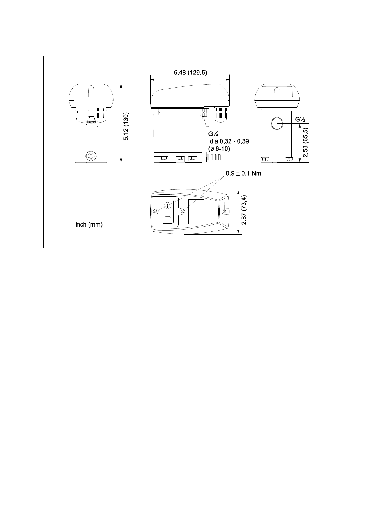
7 Dimension drawing
Pos:33/Be koT echnisch eD okumentati on/Technische Dat en/Masszeich nung @ 0\m od_118456981528 0_15098.doc x @ 15135 @ @ 1
Dimension drawing
Pos:34/--- - Seitenu mbruch ---- @ 0\mod _1157028099 015_0.docx @ 15 320 @ @1
iMAT 32VBI-ELV 9
 Loading...