

Page 1

1
User's Manual
ICP RAID Console
and
ICP RAID Navigator
1st Edition
© Copyright 1998-2000
ICP vortex Computersysteme GmbH
Konrad-Zuse-Str. 9
74172 Neckarsulm - Germany
ICP vortex Corporation
4001 E. Broadway / B-20
Phoenix, AZ 85040, USA
All Rights and Changes Reserved.
01
Page 2

2
Page 3

3
Limited Warranty
Limited WarrantyLimited Warranty
Limited Warranty
ICP vortex Corporation ("ICP vortex") guarantees that this product is free from defects in material
and workmanship. Subject to the conditions and limitations set forth below, ICP vortex will, at its
own option, either repair or replace any part of this product which proves to be defective by reasons
of improper workmanship or materials. Parts used to repair products or replacement products will
be provided by ICP vortex on an exchange basis, and will be either new or refurbished to be functionally equivalent to new.
This warranty does not cover any damage to this product, which results from accident, abuse, misuse, natural or personal disaster, Acts of God, or any unauthorized disassembly, repair or modification. The duration of this warranty is one year from the date of original retail purchase.
Warranty Claim Requirements
Warranty Claim RequirementsWarranty Claim Requirements
Warranty Claim Requirements
To obtain warranty service, return the defective product, freight prepaid and insured, to your local
authorized ICP vortex dealer or distributor, or to ICP vortex Corporation, 4001 E. Broadway, B-20,
Phoenix, AZ 85040. Please note the following: You must include the product serial number, and a
detailed description of the problem you are experiencing. You must also include proof of the date of
original retail purchase as evidence that the product is within the warranty period.
If you need to return the product to ICP vortex, you must first obtain a Return Material Authorization
(RMA) number by calling ICP vortex Corporation at 602-414-0414. This RMA number must be displayed on the outside of your package. Products must be properly packaged to prevent damage in
transit. ICP vortex accepts no responsibility for products which are damaged on arrival due to poor
freight service.
Disclaimers
DisclaimersDisclaimers
Disclaimers
The foregoing is the complete warranty for ICP vortex products and supersedes all other warranties
and representations, whether written or oral. Except as expressly set forth above, no other warranties
are made with respect to ICP vortex products. ICP vortex expressly disclaims all warranties not stated
herein, including, to the extent permitted by applicable law, any implied warranty of merchantability
or fitness for a particular purpose. In no event will ICP vortex be liable to the purchaser, or to any
user of the ICP vortex product, for any data loss, data corruption, damages, expenses, lost revenues, lost savings, lost profits, or any other incidental or consequential damages arising from the
purchase, use or inability to use the ICP vortex product, even if ICP vortex has been advised of the
possibility of such damages.
ICP vortex is not liable for, and does not cover under warranty, any costs associated with servicing
and/or installation of ICP vortex products.
This manual has been validated and reviewed for accuracy. The sets of instructions and descriptions were accurate for ICP Disk Array Controllers at the time of this manual’s production. However, succeeding Controllers, software and manuals are subject to change without notification.
Therefore, ICP vortex assumes no liability for damages incurred directly or indirectly from errors,
omissions or discrepancies between the Controller, software and the manual.
Page 4
4
Pick up the phone
if you need technical support
and dial the numbers:
For Europe: +49-(0)7132-9620-900
For the USA: 602-414-0414
or send us a FAX:
For Europe:
+49-(0)7132-9620-400
For the USA: 602-414-0444
or send us an E-Mail:
For Europe: support@vortex.de
For the USA: support@icp-vortex.com
or check our Website:
http://www.icp-vortex.com
Page 5
5
Important Note
Using modern RAID Systems significantly increases data security and availability. Under no
circumstances does it relieve you from a careful and daily backup on tape or a similar backup
media. This is the only method to protect your valuable data against total loss (e.g.,
through fire or theft), accidental deletion, or any other destroying impacts.
Many Thanks to all my Friends
Monika & Wolfgang (the grandmasters)
AnnDee, Lois, Jeniffer, Valerie, Carl, Frank, Ken (the right one) and William (the Phoenix Crew)
Achim, Dieter, Günter, Hooshiar, Johannes, Jörg, Norbert, Otto, Ralph, Sam, Steffen, Winfried
Brigitte, Alfred (AB, "We need clustering. I say we have it") and Ruediger
Andreas (AK, or "Kopf nur mit ö")
Michael (Mipf, "where is my CPU ?")
Jürgen (Jogo, "Hi, is Jurgen there ?")
Jürgen (JB, "diesbezüglich & hinsichtlich or probably")
Markus (Malu, "Luuuuu...."), Uwe, Ralf
All the fantastic "rest" of this incredible company.
It is not only a pleasure to work here, it is a passion.
Page 6

6
FCC Compliance
FCC ComplianceFCC Compliance
FCC Compliance Statement
Statement Statement
Statement
Information for the User
NOTE: This equipment has been tested and found to comply with the limits for a Class B
digital device, pursuant to Part 15 of the FCC Rules. These limits are designed to provide
reasonable protection against harmful interference in residential installations. This equipment generates, uses, and can radiate radio frequency energy, and if not installed and used
in accordance with the instructions, may cause harmful interference to radio communications. However, there is no guarantee that interference will not occur in a particular installation. If this equipment does cause harmful interference to radio or television reception,
which can be determined by turning the equipment off and on, the user is encouraged to
try to correct the interference by one or more of the following measures:
- Reorientate or relocate the receiving antenna.
- Increase the separation between the equipment and the receiver.
- Plug the equipment into an outlet on a circuit different from that to which the receiver is
powered.
- If necessary, consult the dealer or an experienced radio/T.V. technician for additional
suggestions.
The use of a non-shielded interface cable with the referenced device is prohibited.
Changes or modifications not expressly approved by ICP vortex Computersysteme GmbH
could void the authority to operate the equipment.
Page 7

7
Table of Contents
I. The Program ICPCON......................................................................................................................................12
I.1 Loading ICPCON .....................................................................................................................................12
I.1.1 Loading the ICPCON Program Under NetWare......................................................................................12
I.1.2 Loading the ICPCON Program Under Solaris 7 .....................................................................................13
I.1.3 Loading the ICPCON Program Under Windows NT / 2000.....................................................................13
I.1.4 Loading the ICPCON Program Under Windows 95/98...........................................................................13
I.1.5 Loading ICPCON Under SCO UNIX ......................................................................................................13
I.1.6 Loading ICPCON Under LINUX............................................................................................................14
I.2 The ICPCON Program ..............................................................................................................................14
I.2.1 Select Interface ................................................................................................................................15
I.2.2 Select Controller ...............................................................................................................................16
I.2.3 The two Menu Areas „Monitor“ and „Express/Advanced Setup“ ............................................................16
I.3 The Menu Monitor ..................................................................................................................................17
I.3.1 Menu Monitor: View Statistics............................................................................................................17
I.3.2 Menu Monitor: View Events ...............................................................................................................18
I.3.3 Menu Monitor: View Hard Disk Info....................................................................................................18
I.3.4 Menu Monitor: Save Information........................................................................................................19
I.4 The Menu Express/Advanced Setup...........................................................................................................20
I.4.1 Menu Express Setup: Configure Host Drives .........................................................................................20
I.4.2 Menu Express Setup: Repair Array Drives.............................................................................................24
I.4.3 Menu Advanced Setup: Configure Controller ........................................................................................26
I.4.3.1 Menu Advanced Setup: Configure Controller, Controller Settings..................................................26
I.4.3.2 Menu Advanced Setup: Configure Controller, Firmware Update ...................................................27
I.4.3.3 Menu Advanced Setup: Configure Controller, Intelligent Fault Bus...............................................27
I.4.3.4 Menu Advanced Setup: Conf. Controller, Non-Intelligent Enclosures.............................................27
I.4.3.5 Menu Advanced Setup: Configure Controller, Advanced Settings..................................................29
I.4.3.6 Menu Advanced Setup: Configure Controller, Cluster Settings ......................................................29
I.4.3.7 Menu Advanced Setup: Configure Controller, Clear Log Buffer .....................................................29
I.4.4 Menu Advanced Setup: Configure Physical Devices...............................................................................29
I.4.4.1 Menu Advanced Setup: Configure Phys. Devs., SCSI Parameter /Initialize ....................................31
I.4.4.2 Menu Advanced Setup: Configure Phys. Devs., Format Disk ........................................................32
I.4.4.3 Menu Advanced Setup: Configure Phys. Devs., Check Surface......................................................32
I.4.4.4 Menu Advanced Setup: Configure Phys. Devs., View Status/Defects .............................................32
I.4.4.5 Menu Advanced Setup: Configure Phys. Devs., Deinitialize Disk...................................................32
I.4.4.6 Menu Advanced Setup: Configure Phys. Devs., Lock/Unlock Disk.................................................33
I.4.4.7 Menu Advanced Setup: Configure Phys. Devs., Enclosure Status..................................................33
Page 8

8
I.4.5 Menu Advanced Setup: Configure Logical Drives ..................................................................................35
I.4.6 Menu Advanced Setup: Configure Array Drives.....................................................................................36
I.4.6.1 Menu Advanced Setup: Configure Array Drives, Change Drive Name ............................................37
I.4.6.2 Menu Advanced Setup: Configure Array Drives, Expand Array Drive..............................................37
I.4.6.3 Menu Advanced Setup: Configure Array Drives, Add RAID 1 Component .......................................37
I.4.6.4 Menu Advanced Setup: Configure Array Drives, Replace Array Component ....................................37
I.4.6.5 Menu Advanced Setup: Configure Array Drives, Remove RAID 1 Component .................................37
I.4.6.6 Menu Advanced Setup: Configure Array Drives, Remove Array Drive.............................................38
I.4.6.7 Menu Advanced Setup: Configure Array Drives, Add Hot Fix Drive................................................38
I.4.6.8 Menu Advanced Setup: Configure Array Drives, Remove Hot Fix Drive ..........................................39
I.4.6.9 Menu Advanced Setup: Configure Array Drives, Hot Fix Pool Access..............................................39
I.4.6.10 Menu Advanced Setup: Configure Array Drives, Parity Verify .....................................................39
I.4.6.11 Menu Advanced Setup: Configure Array Drives, Parity Recalculate .............................................39
I.4.6.12 Menu Advanced Setup: Configure Array Drives, Build/Rebuild Progress ......................................39
I.4.6.13 Menu Advanced Setup: Configure Array Drives, Create new Array Drive ......................................40
I.4.7 Menu Advanced Setup: Configure Host Drives......................................................................................41
I.4.7.1 Menu Advanced Setup: Configure Host Drives, Change Drive Name .............................................42
I.4.7.2 Menu Advanced Setup: Configure Host Drives, Swap Host Drives.................................................42
I.4.7.3 Menu Advanced Setup: Configure Host Drives, Remove Host Drives .............................................42
I.4.7.4 Menu Advanced Setup: Configure Host Drives, Split Host Drive....................................................42
I.4.7.5 Menu Advanced Setup: Configure Host Drives, Merge Host Drives................................................42
I.4.7.6 Menu Advanced Setup: Configure Host Drives, Partition Host Drives.............................................42
I.4.7.7 Menu Advanced Setup: Configure Host Drives, Overwrite Master Boot Code ..................................42
I.4.7.8 Menu Advanced Setup: Configure Host Drives, Drive Type (Cluster)..............................................42
II. ICP RAID Navigator.......................................................................................................................................44
II.1 Introduction ..........................................................................................................................................44
II.2 The ICP RAID Navigator "Controls"...........................................................................................................45
II.2.1 The Toolbar.....................................................................................................................................45
II.2.2 The Status Bar ................................................................................................................................45
II.2.3 "Window" Menu Commands .............................................................................................................45
II.2.4 "Help" Menu Commands..................................................................................................................46
II.2.5 "File" Menu Commands....................................................................................................................46
II.2.6 "View" Menu Commands..................................................................................................................46
II.2.7 The "Chart" Menu............................................................................................................................47
II.2.8 The "Configuration" Menu Commands................................................................................................47
II.3 Select Controller ....................................................................................................................................48
II.4 Physical Configuration Window ...............................................................................................................48
II.4.1 Controllers ......................................................................................................................................49
II.4.2 I/O Processors.................................................................................................................................51
II.4.3 Direct Access Devices........................................................................................................................52
Page 9

9
II.4.4 Non direct access devices (raw devices)..............................................................................................56
II.5 Logical Configuration Window.................................................................................................................57
II.5.1 The Host Drive Information Window ..................................................................................................60
II.5.2 The Array Drive Information Window .................................................................................................60
II.5.3 The Logical Drive Information Window...............................................................................................62
II.5.4 Change the name of a Drive .............................................................................................................63
II.5.5 Remove a Host Drive .......................................................................................................................63
II.5.6 Create a new Host Drive...................................................................................................................63
II.5.7 Parity Verify....................................................................................................................................64
II.5.8 Parity Recalculate............................................................................................................................64
II.5.9 Progress Information........................................................................................................................65
II.5.10 Expansion of an Array....................................................................................................................65
II.5.11 Add a Hot Fix Drive........................................................................................................................66
II.5.12 Remove a Hot Fix Drive..................................................................................................................67
II.5.13 Hot Fix Pool Access........................................................................................................................67
II.5.14 Add a RAID 1 Component (Mirror a Drive)........................................................................................67
II.5.15 Remove a RAID 1 Component (Remove a Mirror Drive)......................................................................68
II.5.16 Replace a Logical Drive ..................................................................................................................68
II.5.17 The Different States of an Array Drive ..............................................................................................68
II.6 The Statistics Window ............................................................................................................................71
II.7 The Controller Events Window.................................................................................................................72
II.8 ICP RAID Navigator Help ........................................................................................................................73
II.9 ICP Service and ICP Mail ........................................................................................................................74
Page 10

10
Page 11

11
Chapter I
ICP RAID Console
ICP RAID ConsoleICP RAID Console
ICP RAID Console
ICPCON
ICPCONICPCON
ICPCON
Page 12

12
I. The Program ICPCON
ICP RAID Console (ICPCON) is an extremely helpful and flexible setup and diagnosis tool
for the configuration, monitoring, maintenance and tuning of mass storage subsystems
which are based on one or more ICP Controllers. Different to the ICP RAID Navigator (a
GUI-style application for Windows 9x/NT/2000), ICPCON's user interface is characteroriented and available for all operating systems. (Information on the ICP RAID Navigator
can be found in a separate chapter of this User's Manual.). In addition to that ICPCON is
also part of the ICP Controller’s Flash-RAM and can be loaded at system boot level by
pressing <CTRL><G>.
Some of the key features of ICPCON:
ICPCON includes both, diagnosis and configuration functions
ICPCON is available as both, an executable program under various operating sys-
tems, and rom-resident program loadable with <CTRL>-<G> at system boot level
(i.e., without any operating system)
Host Drives can be setup and configured under normal operation
Online Capacity Expansion of existing Disk Arrays
Enhanced repair functions for Disk Arrays with failed drives
Monitoring functions indicate the performance of the various components, Cache
statistics
Available for MSDOS, NetWare 3.x/4.x/5.x, Windows 9x, Windows NT, Windows 2000,
Linux, SCO Unix
Loadable locally (on the server) or remotely from an authorized workstation (support
of various protocols); NetBIOS, IPX/SPX, TCP/IP.
I.1 Loading ICPCON
As mentioned before, the ICPCON program is available for various operating systems.
It can be used either locally or remotely. This means that all ICP Controllers in a network
can be monitored and serviced from one (or several) workstation(s).
I.1.1 Loading the ICPCON Program Under NetWare
The ICPCON program for NetWare is part of the ICP System CDROM.
ICPCON can be used either under NetWare 3.x, NetWare 4.x, or NetWare 5.x. There are two
different methods of loading ICPCON:
- loading ICPCON on the fileserver
- loading ICPCON on an authorized workstation (remote)
Loading ICPCON on the fileserver. Beforehand, the ICP NetWare driver and the autoloading module CTRLTRAN must have been loaded on the fileserver.
LOAD ICPCON ENTER
on the fileserver.
Page 13

13
Loading ICPCON on a workstation. In this case, too, the ICP NetWare driver and the autoloading module CTRLTRAN must have been previously loaded on the fileserver console. In
addition, the module CTRLIPX.NLM has to be loaded. This module searches for a file
named CTRLIPX.CFG. This file must be located in the same directory as CTRLIPX.NLM.
The system administrator has to set up a user group named ICP_OPERATOR. All users belonging to this group are given access (through ICPCON) to the ICP Controller(s) in this
specific fileserver (Access level 0). Now, the ICPCON program can be loaded from one (or
more) workstation(s):
ICPCON ENTER
I.1.2 Loading the ICPCON Program Under Solaris 7
The ICPCON program for Solaris 7 is part of the ICP System CDROM. To load the program
under Solaris 7, enter:
ICPCON ENTER
I.1.3 Loading the ICPCON Program Under Windows NT / 2000
The ICPCON program for Windows NT / 2000 is part of the ICP System CDROM. To load the
program under Windows NT / 2000, enter:
ICPCON ENTER
For using ICPCON to monitor the server(s) remote, the MON4SOCK.DLL has to be loaded
in addition (must be located in the same directory as ICPCON). It supports SPX/IPX and
TCP/IP network protocols (for NetBIOS you can load instead MON4NETB.DLL).
I.1.4 Loading the ICPCON Program Under Windows 95/98
The ICPCON program for Windows 95/98 is part of the ICP System CDROM. To load the program under Windows 95/98, enter:
ICPCON ENTER
For using ICPCON to monitor the server(s) remote, the MON4SOCK.DLL has to be loaded
in addition (must be located in the same directory as ICPCON). It supports SPX/IPX and
ICPCON ENTER
I.1.5 Loading ICPCON Under SCO UNIX
In order to be able to use the ICPCON program under SCO UNIX (2.x, 4.x and 5.x), it becomes necessary to substitute the standard terminal entry by a new one:
cd /usr/lib/terminfo ENTER
tic gdt386.src ENTER
Before each loading of ICPCON, this terminal has to be activated by:
TERM = gdt386 ENTER
export TERM ENTER
Page 14

14
These two lines can also be inserted in the .profile file and will then be automatically
processed during each login. The ICPCON program itself is copied during the SCO UNIX
installation into the /etc directory. ICPCON is loaded by entering:
icpcon ENTER
I.1.6 Loading ICPCON Under LINUX
The ICP System CDROM includes two archives:
Icpcon.tgz ICPCON and object files (intel)
icpcona.tgz ICPCON and object files (alpha)
These archives include all object files to create ICPCON, as well as an executable ICPCON
compiled on a current Linux version. If you encounter problems with this executable
ICPCON, you can easily compile a new ICPCON on your own Linux system:
unpack the tgz-file: 'tar xvfz icpcon.tgz'
compile ICPCON: 'make'
start ICPCON: './icpcon'
In order to be able to compile ICPCON you need the C-compiler and the Kernel sources on
your system. The link /usr/src/linux has to point to the Kernel sources which correspond
with the currently booted Kernel of your system. This is important for "signature.c" to use
the right magic for the communication with the driver. Otherwise it may happen that you
get "Wrong signature" when trying to start ICPCON.
ICPCON is loaded by entering:
icpcon ENTER
I.2 The ICPCON Program
As mentioned before, the ICPCON program appears identical for all operating systems.
Thus, we can demonstrate the use and functioning of this program regardless of the operating system used. In previous chapters we have already described the hierarchical structure of the ICP firmware. We have defined 4 different levels of hierarchy: Level 1 where the
physical devices named Physical Devices are found, level 2 containing the Logical Drives
(made up of one or several Physical Drives), level 3 where we have the Array Drives, and finally, level 4 where the Host Drives are. Only the latter ones are known to the operating system. The drive of a given level of hierarchy is always set up by using the drives of the next
lower level as components. Accordingly, ICPCON has various menu options, each referring
to one level of hierarchy
Host Drives Level 4
Arrays Drives Level 3
Logical Drives Level 2
Physical Devices Level 1
The following summary gives you an overview of all Host Drive types you can create with
the ICP Firmware. The ICP Controller can simultaneously control several Host Drives of
most various types. For instance, MS-DOS drive C could be a Host Drive of the type disk
(consisting of a single hard disk), MS-DOS drive D is a type RAID 5 Array Drive, MS-DOS
drive E is a Host Drive of the type chain, and MS-DOS drive F is a CD-ROM which communicates with MS-DOS through corelSCSI and the GDT ASPI manager.
Page 15
15
Type of Host Drive Description of Host Drive Minimum number of hard disks
Disk 1:1 assignment: Host Drive to hard disk
(sometimes also called JBOD)
1
Chain Concatenation of several hard disks 2
RAID 1 Mirroring 2
RAID 0 Data Striping 2
RAID 4 Data Striping with parity drive 3
RAID 5 Data Striping with striped parity 3
RAID 10 Combined RAID 0 and 1 4
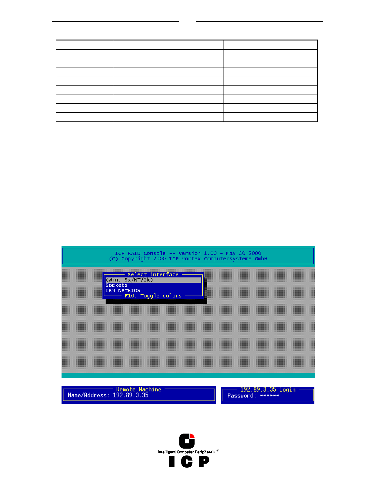
After loading ICPCON, the following screen appears (by pressing F10 you may toggle between black and white display or colored display).
I.2.1 Select Interface
„Interface“ represents the method of how ICPCON connects with the ICP Controller.
In this example „Win. 9x/NT/2k“ means that this ICPCON is the Windows version and is
loaded on a Windows system.
If you press ENTER, ICPCON scans this local system for ICP Controllers. Instead of „Win.
9x/NT/2k“ you could also find here „Linux“, „NetWare“, etc.
Selecting „Sockets“ allows for the remote connection of this workstation with servers using
ICP Controllers. You can either choose TCP/IP or IPX/SPX network protocols. In order to access the servers with ICP Controllers, the corresponding remote service must be loaded on
the server. In addition the supervisor has to setup users and assign access rights (Name,
password, see also chapter II.9)
Page 16
16
After selecting „Sockets“ and „TCP/IP“ you may enter the IP address of the server (if you
would have chosen „SPX/IPX“ ICPCON would scan the network for suitable servers, which
have SPX/IPX protocol). After that you may enter your user name and password.
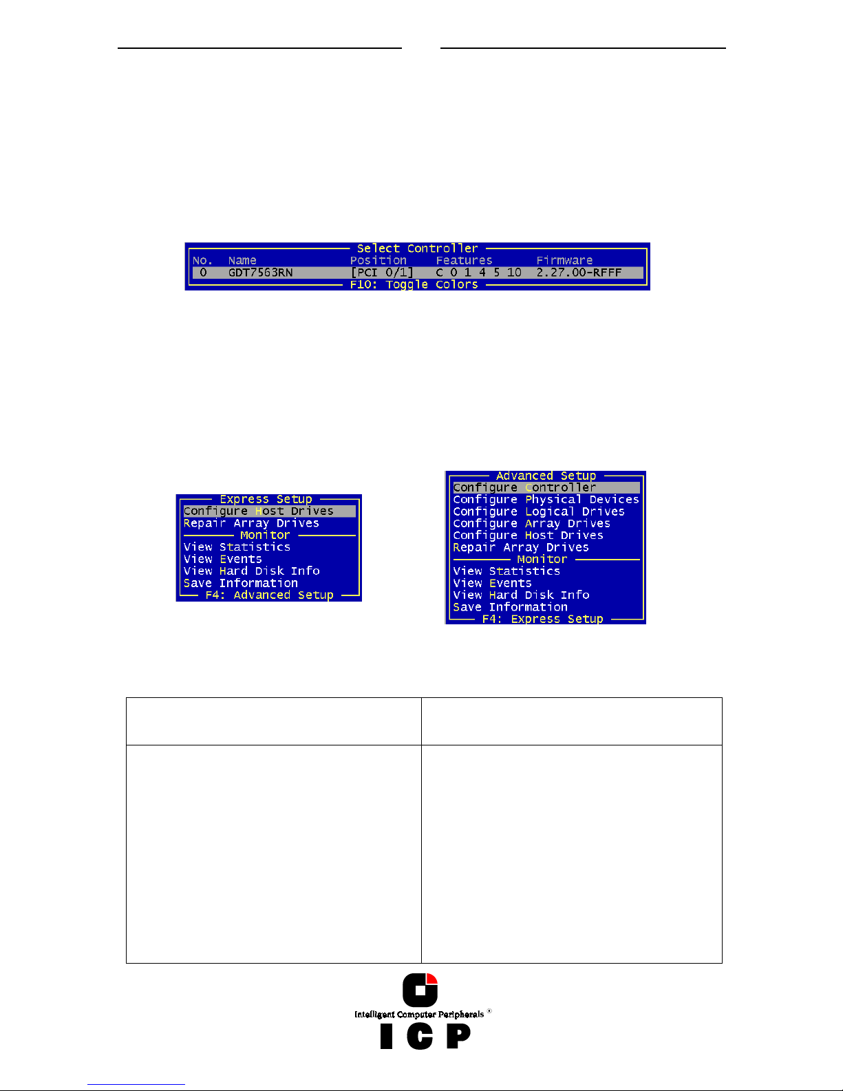
I.2.2 Select Controller
After this login procedure ICPCON delivers a list of ICP RAID Controllers which are installed
in this server (in this example one GDT7563RN). This list contains information on the controller name, the PCI Bus system (0=primary, 1=secondary, etc.) and separated with a slash
the PCI slot number, the controller`s features (C=Chaining, 0=RAID 0, 1=RAID 1, 4=RAID 4,
5=RAID 5, 10=RAID 10) and the firmware level. After selecting the controller with ENTER,
all further settings and changes to these settings within ICPCON refer to this ICP Controller
and the connected devices.
I.2.3 The two Menu Areas „Monitor“ and „Express/Advanced Setup“
ICPCON offers two fundamentally different operating modes:
Express Setup / Advanced Setup with configuration functions
Monitor with monitoring functions
The various menu options can be selected either with the cursor up/down keys, or by
pressing the high-lighted character. F4 allows the switching between the Advanced Setup
and Express Setup modes.
Monitor Express Setup / Advanced Setup
With „View Statistics“ you may super-
vise the performance of the different
components of the RAID subsystem.
„View Events“ is an enhanced event
recorder for RAID and controller specific events.
With „View Hard Disk Info“ you can
view detailed information on the connected devices (important are the retries, reassigns, grown defects and last
status information)
„Configure Controller“ allows you to
setup the ICP Controller. Here, you can
change the Cache settings, the termination, the memory test, etc.
With „Configure Physical Devices“ you
can initialize the devices at physical
level, e.g., change the SCSI protocol,
transfer rates, etc.
„Configure Logical Drive“ allows you to
configure or create Logical Drives.
Page 17
17
„Save Information“ creates a complete
protocol file of the current RAID subsystem including all settings of the ICP
Controller and the drives. This file can
be used for documentary reasons or for
remote diagnosis.
„Configure Array Drives“ allows you to
configure or create Array Drives.
With „Configure Host Drives“ you can
either configure already existing Host
Drives, or create new ones. I.e., you can
create under normal operation new
Host Drives without shutting down the
computer.
The „Repair Array Drives“ menu offers
very powerful menu-guided functions to
repair Array Drives which have failed
drives.
I.3 The Menu Monitor
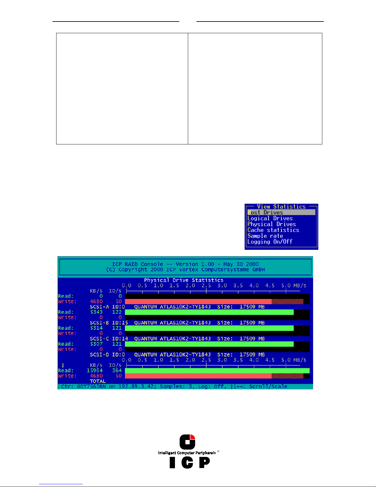
I.3.1 Menu Monitor: View Statistics
In each of these menus, ICPCON displays the performance of the drives of the corresponding level of hierarchy. The throughput of the drives is displayed
in KB/s (KiloBytes per second) and IO/s (I/Os per second,
number of IO’s on the controller). The performance figures
reflect the load being on the controller and not necessarily the
maximum performance the controller can deliver.
After selecting one of the Drives Statistics ICPCON displays a list of all Drives of this level
(for this example the Physical Drives, i.e., level 1). In addition to the performance report on
the Drives, you are given additional information on each device. The ICP I/O channel the
hard disk is connected to, which ID the hard disk has, the name of the hard disk, the gross
Page 18
18
capacity (1MB = 1024KB). The figures shown at TOTAL represent the overall performance of
the Host Drives as a whole. With the ← and → keys you may change the scale of the
graphical KB/s indication. With the ↑ and ↓ keys you can scroll the screen to see further
Drives (if available).
After selecting the menu option „Cache Statistics“ you can view the utilization of the ICP
Controller’s Caches, separated in the Read Cache and the Write Cache.
This menu also displays the size of the Cache in KB and the settings of both Caches (On, or
Off). The figures for „Cache Hits“ show the how often requests can be serviced out of the
cache, i.e., without triggering an immediate Disk IO.
By setting the „Sample Rate”, you can choose the interval at which the ICP Controller delivers new measurements. According to the operating system used, the sampling rate can be
set to a maximum of 60 seconds. The default setting is 1 second.
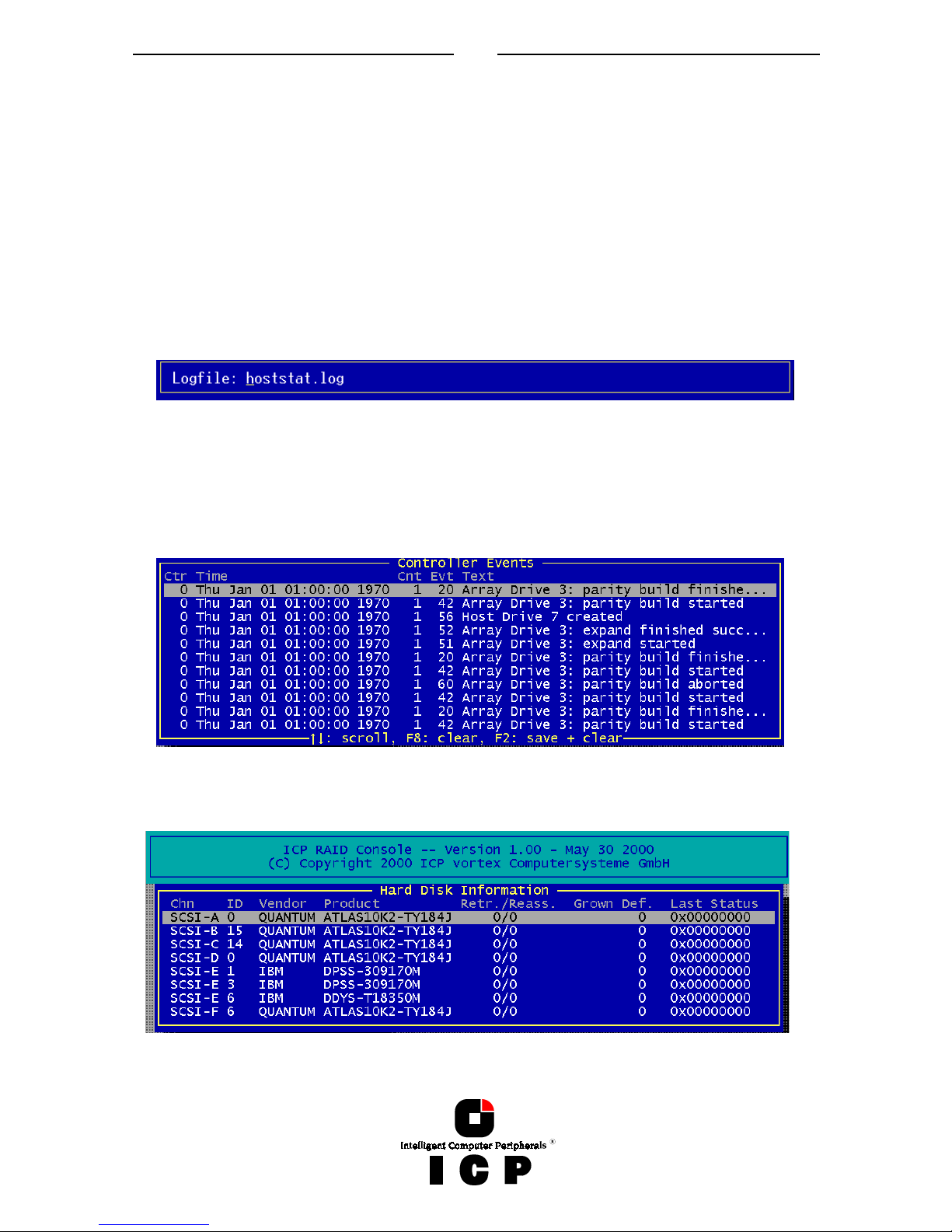
With „Logging On/Off“, you may create a log file which records all the statistic values over a
longer period. If you choose On, ICPCON asks for the path/name of the log file.
I.3.2 Menu Monitor: View Events
With „View Events“ ICPCON displays all ICP Controller Events. They can also be recorded
and saved into a log file. This function gives the administrator a good help to analyze and
supervise ICP Controllers with Array Drives.
I.3.3 Menu Monitor: View Hard Disk Info
This menu shows for all Drives :
Page 19
19
the SCSI channel
the SCSI-ID
the vendor and type
Retries/Reassigns, Grown Defects and the Last Status
(1) The Retries counter is incremented by one unit whenever the ICP Controller retries to ac-
cess a hard disk. If this counter continues to increase (possibly on other hard disks, too) it
is very likely that the cable is not good enough for the selected data transfer rate (cable too
long, poor quality of cable and connectors), or that the SCSI bus is not properly terminated
(too many terminators on the cable, or missing terminator). In very few cases is the hard
disk concerned defective. The retry counter also increases when the SCSI parameters of a
hard disk are changed (see further ahead). Obviously, retries due to this do not imply bad
cabling.
(2) The reassign counter reflects the number of media defects which occur on the hard disk
drive. Defective blocks of the hard disk are assigned substitute blocks (spare blocks) which
are either on the same track, or on alternate ones if all spare blocks on the same track are
already in use. The administration of the reassignments is carried out by the hard disk
through according reassignment tables. Note: If a hard disk works with alternate tracks, it
is generally no longer suitable for applications with high performance expectations. Whenever a defective block is being accessed, the read/write actuator has to move to an alternate
position and this requires extra time.
If you observe that the number of reassigns is constantly increasing, you may suspect that
something is wrong with this drive.
(3) The Grown Defects counter shows the number of media defects which have occurred
since the first time the device was operated with an ICP Controller. A specific hard disk is in
a good condition when it has 0 grown defects. When this counter increases, there is definitely something wrong with the device.
(4) The Last Status information should always be 0x00000000. After a device failure or other
significant events, a different value may be displayed here. This value is volatile and is reset
to 0x00000000 after each power up and/or reset.
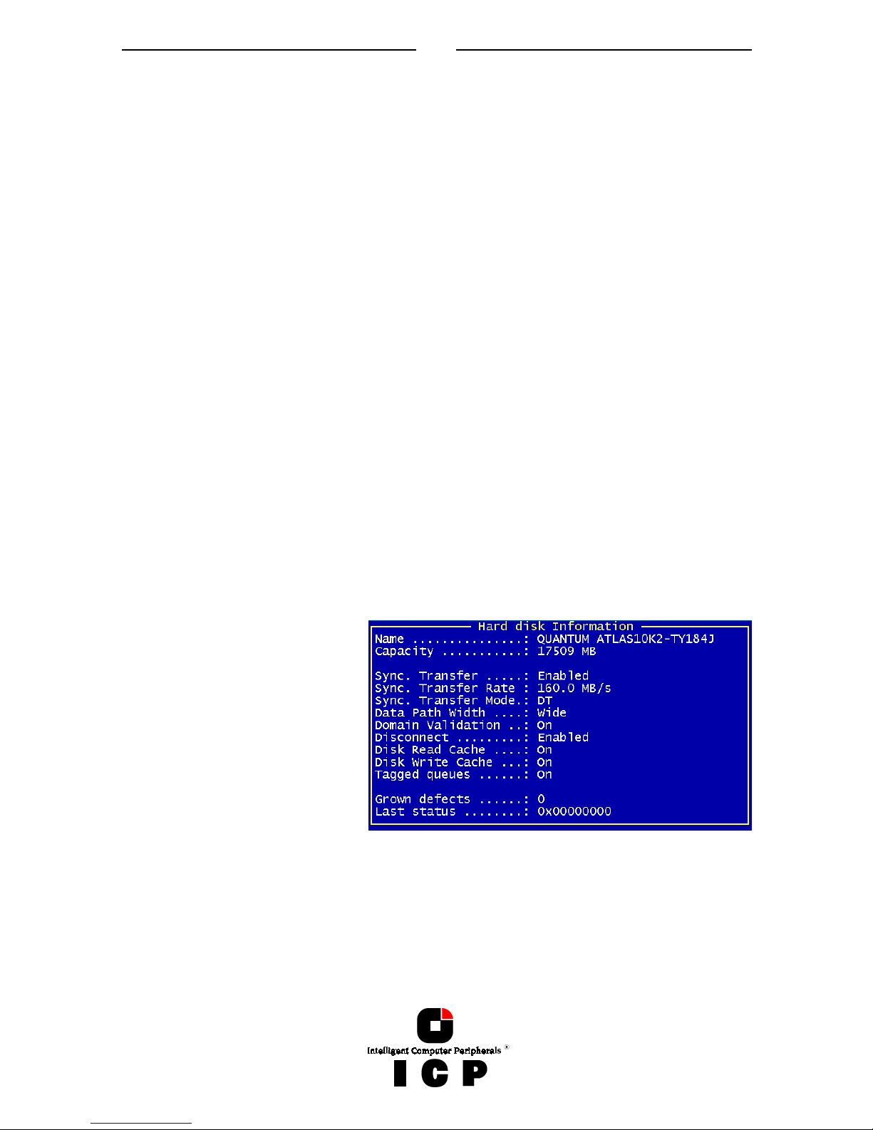
If you press ENTER on a Drive,
ICPCON display further information on the SCSI parameter settings.
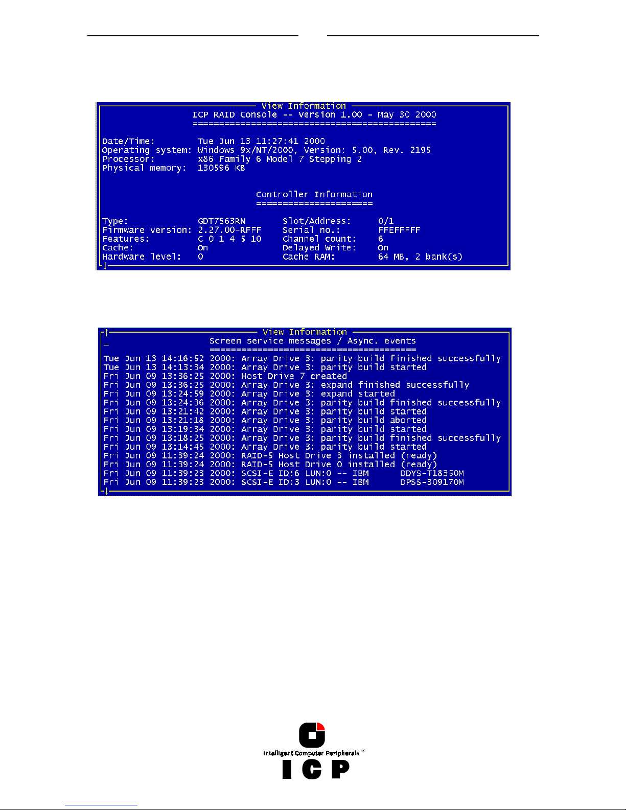
I.3.4 Menu Monitor: Save Information
The Save Information option gives you the possibility to save the configuration information
regarding the selected ICP Controller and its devices in an ASCII-file. This may help if you
require support and is also good for your system documentation.
Page 20
20
At the end of this protocol is a chronological listing of boot messages and other events
stored in the Flash-RAM of the ICP Controller. If the buffer is full, the oldest events are deleted first.
In the menu „Configure Controller“ the logging buffer can be cleared with „Clear Log Buffer“.
The logging list is a good source to analyze complex events and problems.
I.4 The Menu Express/Advanced Setup
I.4.1 Menu Express Setup: Configure Host Drives
This function allows a very easy installation of new Host Drives and does not require any
special knowledge. Apart from minor differences, this menu option is identical with the
menu option „Configure Host Drives“ in the Advanced Setup (in Express Setup, the user
may not select a stripe size (defaults to 128KB) or use the Split/Merge functions.)
Page 21
21
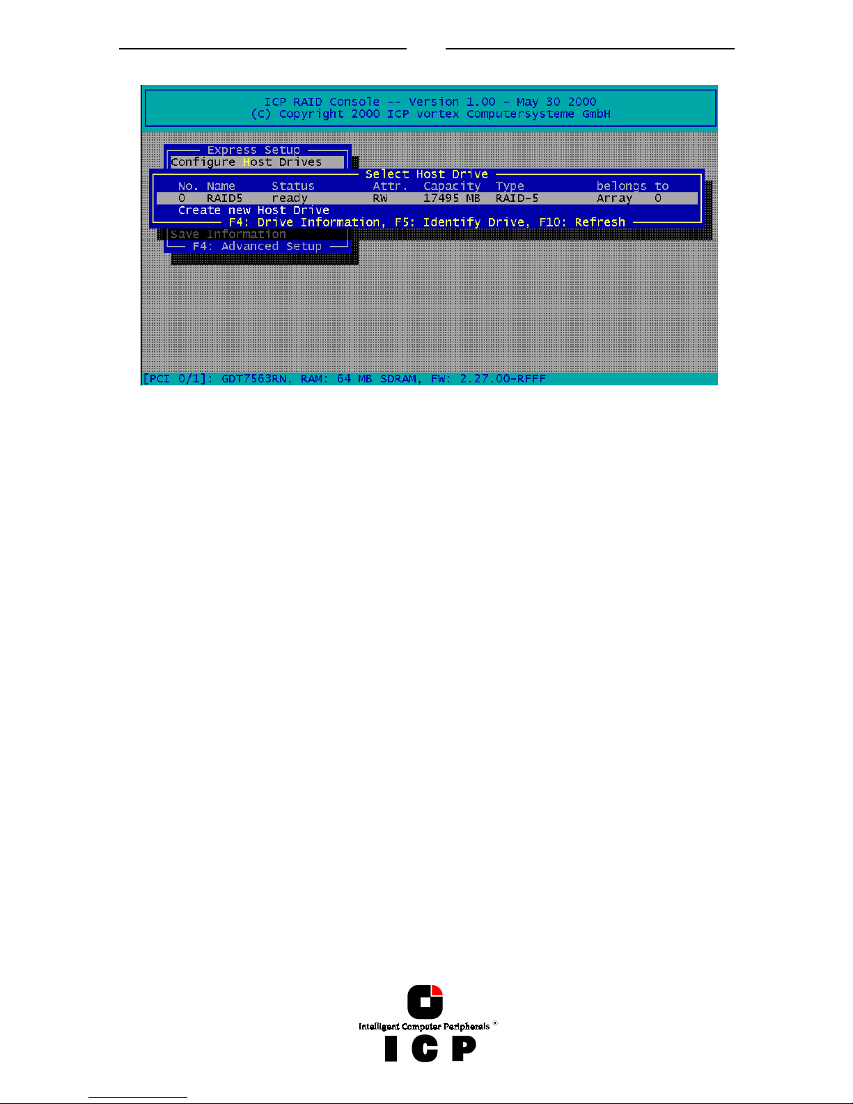
After selecting Configure Host Drives, ICPCON displays a list of already existing Host
Drives. With a new system this list will show no entries. In this example there is already one
Host Drive available. It’s name is ”RAID 5“ and it is an RAID 5 Array Drive (with approx.
17GB capacity). The status is “ready”. I.e., this Host drive is fully available and redundant.
The following states for RAID Host Drives are possible:
"Idle" State
This state is characterized by the fact that the redundant information of the disk array has
never been entirely created. The disk array is in this state after its first configuration and
until you quit ICPCON. If an error should occur while the array is in the build state, the array
returns to the idle state (exception: if during build mode the dedicated drive of RAID 4 fails,
the mode changes to fail).
"Build" State
After the disk array has been configured for the first time, it assumes the build state as soon
as you quit ICPCON. While the array is in the build state, redundancy information is calculated and stored to the hard disks of the array.
"Ready" State
The disk array is fully operational when in the ready state. All redundant information is present, that is, a hard disk can fail without impairing the functionality of the disk array. This is
the normal state of a disk array. The state ready/expand indicates, that the RAID level and/or
capacity are currently migrated/expanded.
"Fail" State
The disk array changes to the fail state whenever a Logical Drive fails. Redundancy information is still present, thus allowing the remaining hard disks to continue working. This state
should be eliminated as soon as possible by replacing the defective hard disk. If a so-called
Hot Fix drive has previously been assigned to a disk array with ICPCON, the controller will
automatically replace the defective drive and start the reconstruction of the data and the
redundant information. Therefore, under these circumstances the fail state is only temporary and will be eliminated by the controller itself.
Page 22

22
"Rebuild" State
The disk array will assume this state after the automatic activation of a Hot Fix drive or after
a manual replacement carried out with ICPCON. The data and the redundant information
are reconstructed and stored to the new drive.
"Expand" State
If the capacity or RAID level of an existing disk array is changed, the disk array changes its
state into expand. As soon as the expansion or migration is completed, the state changes
back to ready.
"Error" State
If a second hard disk should fail while the disk array is in the fail or rebuild state, it is not
possible to continue the working session without restrictions. The disk array is still available for I/Os, but data loss and error messages on the host level are possible.
The following state diagram of the disk array summarizes the states described above and
the transitions from one state to another.
Some of these states may become the addendum patch (e.g. build/patch, ready/patch).
This word indicates that the original Array Drive went through a significant procedure. I.e.,
the parity information was recalculated anew.
Or, the Array Drive has been patched from the error state into the fail state. This may become extremely helpful in a situation where two Logical Drives of an Array Drive, fail at the
same time, but only one of the two Logical Drives is really defective and the other was
blocked out, since it was connected with the same SCSI channel as the defective one. The
Array Drive's state is error and normally all data would be lost. The ICP Controllers include
some functions, which allow the patch of this Array Drive from the error state into the fail
sate. Before the actual patch, the defective drive has to be physically removed from the Array Drive. Such a patch-procedure is a real sheet-anchor and should only be used, after a
detailed consultation with a trained support person (a printout of the Save Information file, is
extremely helpful).
Pressing F4 delivers level by level detailed information on a Host Drive and its components.
This may assist to get an easy overview of a specific Host Drive. After pressing F5 the ICP
Controller switches the LEDs (if available) of the hard disks belonging to that Host Drive on
and off.
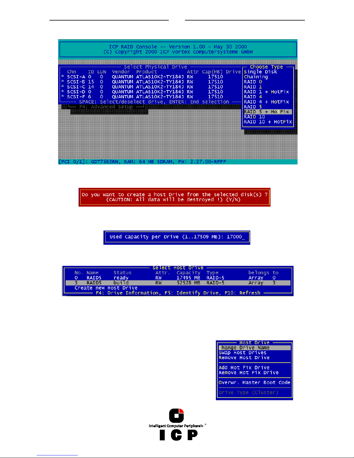
After selecting „Configure new Host Drive“, the ICP Controller scans all channels for free
hard disks (i.e., hard disks which are not yet part of a Host Drive) and displays these units
in a list. Use the Space bar to select/deselect hard disks and the cursor up down keys to
move the selection bar from one hard disk to another. Marked hard disks show an “*" in the
first column. In the choose Type windows all possible Host Drive types are displayed (the
possible types depend on the number of selected hard disks and the firmware level of the
ICP Controller).
Page 23
23
Finish the selection by pressing ENTER.
ICPCON displays a security message pointing out that all existing data on the selected hard
disks will be destroyed after confirming with Yes.
After pressing “Y” the user may limit the capacity per hard disk which will be used for the
Host Drive. This can be very helpful for the procurement of future spare hard disks. After
that ICPCON automatically creates and configures thew new Host Drive and adds it to the
list. All SCSI parameters are adjusted to optimum values.
After leaving ICPCON or after pressing F10 (for refresh) the ICP Controller starts the build
process on this Host Drive. In our example it calculates the parity information and writes it
to the hard disks. The status during this process is build. When the build is successfully
finished the status changes into ready.
If you press ENTER on a Host Drive the following options
become available:
“Change Drive Name” allows you to change the name of a
Host Drive. The name serves to identify a Host Drive with
ICPCON. E.g., you could name the boot Host Drive “Boot”
and the data Host Drive “Data”.
“Swap Host Drives”. When the PCI computer is switched
on, the Host Drives are initialized in the order of the Host
Page 24

24
Drive list, which means that the operating system is booted from the Host Drive having the
lowest number. For reasons of flexibility, a Host Drive's position in the list can be changed.
However, the position of the Host Drive from which the operating system is booted and the
position of the Host Drive from which ICPCON (disk version) was started (both can be the
same), cannot be changed. If you wish to change the position of these drives, you have to
boot the operating system and ICPCON from a floppy disk or use the ICPCON from the
Flash-RAM of the ICP Controller. To change the position of a Host Drive in the Host Drive
list, highlight the Host Drive and confirm with ENTER. Then, type on the new position and
press ENTER.
“Remove Host Drives”. Removing a Host Drive is a serious action. All data will be lost after
removal. If you want to remove a Host Drive belonging to an Array Drive for which several
Host Drives exist (after capacity expansion, or after splitting), all other Host Drives will also
be removed.
“Split Host Drive”. For some purposes it might of interest to split an existing Host Drive
into two or several Host Drives. Each Host Drives looks to the operating system just like a
single hard disk. Since the new Host Drives have smaller capacities ICPCON has to write
new header information on the two Host Drives. All data will be lost.
“Merge Host Drives”. This function reverses the Split Host Drive option. Only such Host
Drives can be merged which belong to the same Array Drive or Logical Drive. Since the new
Host Drives has a larger capacity ICPCON has to write a new header information on the new
Host Drives. All data will be lost.
“Partition Host Drive”. This option is not available, when loading ICPCON from the FlashRAM of the ICP Controller. Before you can partition a new Host Drive it may become necessary to reboot the system, first. The partitioning menu has similar functions as the MS-DOS
program FDISK. You can create and delete a partition and also change the active partition.
MS-DOS can only be booted from an active partition. Just like FDISK, ICPCON can handle
primary partitions, extended partitions, and logical drives within the extended partitions.
“Add Hot Fix Drive” allows you to add a Hot Fix drive to an existing RAID 1, RAID 4, RAID 5,
or RAID 10 Array Drive. There are two different types of Hot Fix drives: Private and Pool Hot
Fix drives. A Pool Hot Fix Drive is a spare drive within the so-called Hot Fix Pool. A drive in a
Hot Fix Pool is available for several Array Drives as a Hot Fix drive. Thus, several Array
Drives can share one Hot Fix drive. Of course, once this drive has been used by one of the
Array Drives, it is no longer available for the others.
A Private Hot Fix drive is dedicated to one RAID 1, RAID 4, RAID 5 or RAID 10 Array Drive.
“Remove Hot Fix Drive” allows you remove a previously assigned Hot Fix drive.
“Overwrite Master Boot Code“. This option creates a valid and consistent master boor record on the selected Host Drive and should be carried out on any new Host Drive on which
Windows NT is installed. Never use this function when the Host Drive contains valid data, all
data will be lost.
The option “Drive Type (Cluster)“ is available only with ICP Controllers which are equipped
with Cluster RAIDYNE® (GDTx6xxx) and allows to assign one Host Drive to several ICP
Controllers (Type Cluster).
I.4.2 Menu Express Setup: Repair Array Drives
This function allows the online repair of Array Drives which show failed drives. After selecting this menu option, ICPCON displays a summary of all installed Array Drives (in this example 2) and the number of Array Drives which are in critical states.
Page 25

25
In this example there is one Array Drive in the FAIL
state. I.e., the Array Drive is still operating but
longer redundant.
After pressing any key, ICPCON displays a list of
Array Drives which are candidates for this online
automatic repair. Note: Array Drives which have the
„ERROR“ state are very critical and have lost 2 or
even more drives. These Array Drives cannot not be
repaired with this function. In such critical cases
the data integrity can longer be maintained. You
may call our technical support center for further
assistance.
After selecting the Array Drive, ICPCON
display the actual drive which has failed. In
this example it is the hard disk which forms
Logical Drive 5.
After confirmation, the failed drive has to be taken out and the new one has to be config-
ured on the same ID an
plugged in again.
ICPCON detects the new drive and expects a clearance to build this drive as a replacement
into the Array Drive.
After that the state of the Array Drive changes into „REBUILD“, i.e. the missing data is reconstructed out of the remaining data and the redundancy information.
Page 26

26
The „ERROR“ state of an Array Drive is very critical. There are several procedures in the ICP
Controller’s firmware to handle such cases an bring back the Array Drive in operation without loosing data. The most suitable procedure for the specific case, should be elaborated
with your system administrator or our technical support. (Note: ICP vortex offers 2-day
RAID Workshops in our training center, which also focus on the resolution of such problems.
I.4.3 Menu Advanced Setup: Configure Controller
I.4.3.1 Menu Advanced Setup: Configure Controller, Controller Settings
Within the Controller Settings all relevant
parameters and settings concerning the
ICP Controller itself can be changed. All
information concerning Physical, Logical,
Array and Host Drives are stored twice
(primary and secondary configuration data) on
each hard disk. I.e., the ICP Controller
itself carries no configuration data of a
specific disk array. Out of this reason, the
migration of Host Drives between ICP
Controllers is very easy and secure, even
if the SCSI IDs and channels are changed.
Simply connect the hard disks to the new
ICP Controller, and the Host Drives will
automatically available again.
The various parameters and settings have
the following meaning:
Parameter Alternatives Description
Cache On
Off
ICP Controller cache (write and read cache) On
ICP Controller cache (write and read cache) Off
Delayed Write On
Off
Write cache On
Write cache Off
BIOS Enabled
Disabled
Removed
BIOS enabled
BIOS disabled, but <CTRL><G> allowed
BIOS and <CTRL><G> disabled
BIOS Warning Level All Messages
Fatal Errors
All ICP BIOS warnings and errors are displayed
Only fatal messages are displayed
SETUP from FlashRAM
Disabled
Enabled
<CTRL><G> not possible
<CTRL><G> allowed
Page 27

27
Display <CTRL><G> Off
On
<CTRL><G> not displayed at system boot level
<CTRL><G> displayed at system boot level
Supported BIOS
Drives
2
7
The ICP BIOS supports 2 drives under MS-DOS
The ICP BIOS supports 7 drives under MS-DOS
CD-ROM Boot Enabled
Disabled
Boot from CD-ROM enabled
Boot from CD-ROM disabled
Memory Test No test
Standard
Double scan
Intensive
No test at all
Standard test
Double scan test
Intensive test (takes longer)
Chn. SCSI-A
Termination
Off
On
Auto
SCSI termination of the channel Off
SCSI termination of the channel On
SCSI termination according to occupied connectors
SCSI-ID 0,1,2,3,4,5,6,7 Possible SCSI IDs of the channel
I.4.3.2 Menu Advanced Setup: Configure Controller, Firmware Update
The firmware, the BIOS and the ICPCON program of the ICP Controller are stored in a FlashRAM which is part of the ICP Controller hardware. In contrast to EPROMs, Flash-RAMs can
be re-programmed many times and without the complicated UV-light erasing procedure.
Firmware, BIOS and ICPCON are part of the GDT_RPFW file. The file has an extension (e.g.
GDT_RPFW.009) which indicates the version stepping. The latest version of the this file can
be downloaded from our Website (www.icp-vortex.com).
This menu option is not available when ICPCON is accessing the ICP Controller remotely.
I.4.3.3 Menu Advanced Setup: Configure Controller, Intelligent Fault Bus
Intelligent Fault Bus is an older subsystem standard, which is no longer used in modern
subsystems or backplanes. ICP’s Ultra/Wide Disk Array Controllers were the last ICP Controllers supporting this, sometimes also called ”DEC™ Fault Bus”.
Today’s modern subsystems are either using SAF-TE (SCSI Accessed Fault Tolerant Enclosures) or SES (SCSI Enclosure Services) as communication links to the controller. These
intelligent subsystems are normally build on so-called backplanes, which host hard disks
which are equipped with SCA connectors (Single Connector Attachments). The backplane
has a dedicated electronics with microprocessor and firmware which allows an intelligent
communication between the subsystem/backplane and the ICP Controller. Through this
channel the subsystem can for example report its temperature and the power supply status
to the ICP Controller. The major objective of SAF-TE or SES is to provide the Auto Hot Plug.
In contrast to the Hot Plug, a defective drive is simply pulled out the subsystem and the
replacement unit is plugged in again. Both, the ICP Controller and the subsystem control
this process so that problems on the SCSI/FC-AL bus are eliminated and the rebuild of the
missing data is initiated fully automatically. No further user interaction is necessary.
A unique and special feature of ICP Controllers is the following:
I.4.3.4 Menu Advanced Setup: Conf. Controller, Non-Intelligent Enclosures
Since SAF-TE or SES subsystems are pretty cost intensive, ICP has integrated a special
functionality which can control up to 16 non-intelligent enclosures with up to 15 hard disk,
each, and provides the Auto-Hot-Plug. It is clearly up to the user’s responsibility to use
components (e.g., disk shuttles), which are really hot pluggable.
Page 28

28
In this example one subsystem is already defined. Naturally, the hard disks with their disk
shuttles could be also directly mounted in the server enclosure. The term “Enclosure” in
these cases is more a definition set, which includes all hard disks which should be auto hot
pluggable.
The following example shows the slots of the enclosure which have been assigned with
hard disks. To fill an empty slot, press ENTER and select the desired hard disk.
It should be outlined again, that SAF-TE and SES are definitely the better choices for auto
hot pluggable subsystems. Only with these systems a secure Auto Hot Plug is guaranteed.
Page 29

29
With the non-intelligent subsystems we highly recommend you to use only best quality
components (disk shuttles, cables, terminators, etc.).
I.4.3.5 Menu Advanced Setup: Configure Controller, Advanced Settings
Within Advanced Settings there are three settings which control the configuration and address behavior of the ICP Controller’s BIOS and DPMEM. Normally, there is nothing to
change here.
Parameter Alternatives Description
Shrink BIOS after
Post
Off
On
Auto
The BIOS is not shrinked after the post phase
The BIOS is always shrinked after the post phase
The ICP Controller decides on the BIOS shrink
BIOS RAM allocation method
Auto
Older
The BIOS address space is automatically allocated
The BIOS address space is allocated according to an
older PCI specification
DMEM mapping Move below 1MB
Do not move
The DPMEM address space is allocated below 1MB
The DPMEM address space is always above 1MB
I.4.3.6 Menu Advanced Setup: Configure Controller, Cluster Settings
This menu is selectable only with ICP
Controllers which are equipped with
Cluster RAIDYNE® and allows the
user to enable the IO channels of the
ICP Controller for clustering. Special
care must be taken, that the IOProcessors of a shared channel (SCSI
or Fibre Channel) have different IDs, otherwise there will be conflicts.
I.4.3.7 Menu Advanced Setup: Configure Controller, Clear Log Buffer
The ICP Controller records certain events in a logging buffer which is part of the Flash-RAM.
If it is planned to use the ICP Controller in a completely new system, it is sensible to clear
all events in this buffer. The Clear Log Buffer function detects possible entries and deletes
them.
I.4.4 Menu Advanced Setup: Configure Physical Devices
After selection of this menu option ICPCON displays a list of the IO channels (SCSI or Fibre
Channel) and the available devices. This list can be scrolled with the cursor up/down keys.
The first column displays the IO channel (“SCSI“ stands for SCSI and “FCAL“ for FibreChannel). The next column shows the ID followed by the LUN (Logical Unit Number; normally always 0). The next column is either filled with a small “i” (for initialized), or empty.
Initialization means the creation of ICP-specific configuration data on the hard disks and
the adjustment of hard disk specific operating parameters (protocol, transfer rate, etc..).
The next entry lists the vendor and type of device, followed by the drive’s attributes (RW for
Page 30

30
Read/Write; RO for Read Only). The IO-Processors and SAF-TE-Processors (in our example
channel B ID 8: SDR, Inc. GEM312 REV001) to not have attributes. The next column lists the
capacity of the hard disk in MB (1MB = 1024KB; 1GB=1024MB). The last column gives information on the assignment of this Physical Device to a Logical/Array/Host Drive.
With ICP Fibre Channel RAID Controllers, F4 delivers extended information on Fibre Channel drives (World Wide Name, firmware-level and the Link- status of the drive).
If you press F5, the ICP Controller periodically turns the LED (if available) of the corresponding drive on and off. This helps to physically identify a specific drive in an array of
many drives.
If you press F8 you can repair the configuration data of a physical drive. If your ICP Controller should ever display during his boot sequence a message like “Detected Primary Configuration Data error, using Secondary“ or similar, you can try to repair the data with F8.
If you press ENTER on a specific drive ICPCON opens the “Configure Disk” menu. Here, all
relevant adjustments and modifications concerning the physical drives can be carried out.
Note: If you create
new Host Drives
with the Express
Setup function,
ICPCON and the
ICP Controller will
automatically adjust all parameters
to their respective
best values. The
transfer rate per
drive depends on
circumstances like
cables, terminators,
etc.. I.e., if a certain
configuration does
not allow 160 MB/sec, the drive will be automatically “throttled” down to the next troublefree transfer rate.
Page 31

31
I.4.4.1 Menu Advanced Setup: Configure Phys. Devs., SCSI Parameter /Initialize
This option can destroy all data on the hard disk.
If a hard disk is not
yet initialized, you
have to initialize it
first. ICPCON copies ICP specific
configuration
blocks on the hard
disk, a primary
block and a mirrored secondary
block. The possible
settings are different if you select a
SCSI hard disk or a
Fibre Channel hard
disk. With a FCAL
hard disk there are only a few settings which are relevant. You should always check that
they are all "Enabled" or "On". If the hard disk you have selected is an Ultra 160 device and
the ICP Controller has Ultra 160 SCSI channels, F4 “Advanced Configuration“, allows you to
configure the so-called “Domain Validation“ (a cyclical check of the correct data transfer at
a given rate). Normally this parameter is On.
The various settings have the following meanings:
Sync. Transfer: Enabled
The SCSI-bus knows two methods of data transfer: asynchronous and synchronous transfer.
Each SCSI device must be able to perform the first type of transfer, the second one is optional. The advantage of the synchronous transfer consists in a higher data transfer rate,
since the signal transfer times on the possibly long SCSI-cable have no influence on the
transfer rate anymore. Two SCSI-bus participants which want to exchange data between
each other have to check if and how (i.e., with which parameters) a synchronous data
transfer between them is possible. Therefore, the mere setting does not automatically enable synchronous data transfer; this mode is only effective if both devices support it and
after they have checked their capability of communicating with each other in this mode.
Sync. Transfer Rate
This is the synchronous data transfer rate in MB/s. Ultra 160 SCSI allows up to 160 MB/s.
If a given SCSI-cable does not allow a certain transfer rate, it can be reduced to a value that
allows a trouble-free data transfer. The reason for such a restriction is not necessarily a
"bad" SCSI-cable. Lowering the transfer rate may also become necessary when you set up a
special configuration which does not allow full speed.
Disconnect: Enabled
The concept of the SCSI-bus allows several participants. It is particularly important to guarantee a high degree of action overlapping on the SCSI-bus. This high degree of overlapping
becomes possible when a SCSI device has an enabled “Disconnect”.
Disk Read Cache / Disk Write Cache / Tagged Queues
Out of performance reasons, the read ahead and write cache of the hard disk should be always On. Tagged Queues is a SCSI feature which allows the drive to execute more than one
command at a time, if available, it should also be On.
Page 32

32
If you leave this configuration form with <ESC> and you have made changes, ICPCON displays a security request. The warning of the destruction of all data implies different evaluations, depending on the device's current state and the options you selected:
First Initialization of the Device. In this case, the warning must be taken seriously. If the drive
was previously connected to a different controller (e.g. NCR etc.) and still contains important data, this data will be lost now.
The Device was already initialized. If only internal parameters such as Disconnect, Synchronous
Transfer, and Disk Read/Write caches, or tagged queues have been changed, the data on the
drive remains intact. Only the function state of the device changes.
I.4.4.2 Menu Advanced Setup: Configure Phys. Devs., Format Disk
This option destroys all data on the hard disk.
All manufacturers of hard disks deliver their products already formatted and surface-tested.
For new hard disks it is neither necessary, nor advisable to perform the Format Disk. This
procedure is only indicated if you have doubts on the hard disk's condition.
The time required for the Format Disk of a hard disk depends on the hard disk itself. It can
take quite a long time (up to days !). Often it seems that nothing happens and that the system hangs (no LED indication). If you put your ear on the hard disk you can hear the actuator stepping (with some drives one step per minute or longer). Never interrupt a Format
Disk procedure. This may lead with a very high probability to a non-functioning hard disk.
Before the actual formatting, ICPCON asks you whether the "Grown Defect" table of the
hard disk should be deleted. Some users believe that this makes a hard disk with a lot of
grown defects like new. This is wrong. As soon as the bad sectors are accessed again, a reassign will happen, generating a new grown defect.
I.4.4.3 Menu Advanced Setup: Configure Phys. Devs., Check Surface
This option destroys all data on the hard disk.
This option allows the checking of the surfaces of the hard disk media. The ICP Controller
writes and reads certain data patterns and checks them for correctness.
After confirming the security request, a progress information is displayed. You can interrupt
the Check Surface option by pressing <ESC>.
I.4.4.4 Menu Advanced Setup: Configure Phys. Devs., View Status/Defects
Grown defects. Number of media defects that have occurred
in addition to the media defects the hard disk already had
upon delivery.
Primary defects. Number of media defects that the hard disk
already had upon delivery.
Last status: The Last Status gives detailed information on the last failure of a hard disk.
The information is only present until the next hard reset of the system and may help for
deeper failure analysis or tracing.
I.4.4.5 Menu Advanced Setup: Configure Phys. Devs., Deinitialize Disk
This option destroys all data on the hard disk.
This menu option allows you to de-initialize a hard disk which has previously been initialized for use with the ICP Controller. By doing so, the specific ICP information present on
the device is removed. Obviously, the de-initialization cannot restore data that was lost
during initialization.
Page 33

33
I.4.4.6 Menu Advanced Setup: Configure Phys. Devs., Lock/Unlock Disk
This option is only high-lighted when you have selected a removable hard disk (e.g., Syquest, Iomega). Before you can initialize a cartridge you have to lock it. Before removing it
you have to unlock it.
I.4.4.7 Menu Advanced Setup: Configure Phys. Devs., Enclosure Status
After selecting this option you can either view the Enclosure Status or view/configure the
enclosure slots. Before you can use the Auto Hot Plug with a SAF-TE subsystem, you first
have to configure the subsystem (more precisely it's intelligence, the so-called SEP - SAFTE Enclosure Processor).
To assign a specific hard disk to a SAF-TE enclosure slot, press ENTER on the empty slot
and choose one of the hard disks.
The next page shows a block diagram of a SAF-TE subsystem.
Page 34

34
SEP
FAN
F
A
N
Power
Supply
Status LEDs
Hot Plug
Control
H
a
r
d
D
i
s
k
SCSI
Channel
ICP
Disk Array
Controller
Power
Supply
Door
Lock
Temperature
Page 35

35
I.4.5 Menu Advanced Setup: Configure Logical Drives
Logical Drives (hierarchy level 2) are installed in this main menu option.
Selecting Configure Logical Drives leads you to the screen shown next.
The F4 key gives you a list of all the hard disks this Logical Drive consists of. If it is a Logical
Drive of the type Disk, it only consists of one single hard disk. If a Logical Drive consists of
more hard disks, it is of the type Chain (concatenation of several hard disks).
F3 loads the media of removable hard disks and F5 turns for some seconds periodically the
hard disks LED on and off.
To configure and setup an new Logical Drive, select Create new Logical Drive. ICPCON displays a list of free Physical Drives (which are not already part of a Logical drive).
If you select one Physical Drive with SPACE and press ENTER, ICPCON suggests to create a
SINGLE Drive out of this hard disk.
Page 36

36
If you confirm with <Y>, ICPCON allows you to limit the size of the Logical Drive. This becomes interesting when you configure later on an Array Drive with several identical Logical
Drives and you want to make sure that you get appropriate spare hard disks in the future. It
would be bad luck if the new hard disk would have 17508MB, only. It simply wouldn't fit
into the Array Drive. If you limit the capacity
to e.g., 17000MB from the beginning, you can
be sure that all future 18GB hard disk will
have at least 17000MB and thus can be used as spare hard disk.
If you select two or more Physical Drives with SPACE, ICPCON suggest the creation of a
Logical Drive of the type Chain. In some literature Disk Chaining is also called Disk Spanning.
You can picture the functioning mechanism of a type Chain Logical Drive as follows: all hard
disks forming the Logical Drive are linked together one by one in the exact same order in
which they have been selected with the SPACE bar. This concatenation can be compared
with a chain. If, for example, the Logical Drive consists of 4 hard disks with 2000MB each,
the Logical Drive will have a capacity of 8000MB. When data is written to this Logical Drive,
the first hard disk is filled first, then the second, and so on.
Although it is not advisable, Logical Drives of the type Chain, can also be components of
Array Drives.
I.4.6 Menu Advanced Setup: Configure Array Drives
This main menu option allows you to configure Array Drives (level of hierarchy 3).
Array Drives with the following listed RAID levels can be configured within this menu.
RAID 0 pure data striping without redundancy
RAID 1 disk mirroring
RAID 4 data striping with dedicated parity drive
RAID 5 data striping with striped parity
RAID 10 RAID 0 combined with RAID 1
The ICP Controller can manage up to 35 Array Drives (with different RAID levels) simultaneously. Obviously, the physically existing number of hard disks will limit the number of parallel used Arrays.
F4 displays level by level detailed information on the selected
Array Drive (the structure, the order, which hard disks are part
of the Array Drive). With F5 the ICP Controller turns for a few
seconds the LEDs of all hard disks belonging to this Array
Drive periodically on and off. This may help to identify the hard
disks.
If you press ENTER on a specific Array Drive ICPCON displays a
list of possible options.
Page 37

37
I.4.6.1 Menu Advanced Setup: Configure Array Drives, Change Drive Name
This command allows you to change the name of an Array Drive. The name serves to identify an Array Drive in ICPCON or ICP RAID Navigator. This can be very helpful for configurations where several Host Drives of various types are operated by a single controller.
I.4.6.2 Menu Advanced Setup: Configure Array Drives, Expand Array Drive
The Expand Array Drive option which is also available with
ICP RAID Navigator, contains three major functions:
1. Conversion of a free space on the Logical Drives into a
separate Host Drive
2. Migration of the RAID level of a given Array Drive
RAID 0 -> RAID 4 and vice versa
RAID 0 -> RAID 5 and vice versa
3. Expansion of the capacity of a given Array Drive
To initiate a migration or expansion with a RAID 4/5 Array Drive, the state must be ready.
The data on the Array Drive remain intact and are not affected by the expansion.
The additional capacity is introduced as new Host Drive. If a Logical Drive fails during the
expansion, the expansion process continues until the expansion is finished. The Array Drive
changes into the fail state.
I.4.6.3 Menu Advanced Setup: Configure Array Drives, Add RAID 1 Component
In certain "emergency" cases this is a very powerful and helpful option. This function allows
you to add to a Logical Drive which is member of an Array Drive, another Logical Drive as a
mirror drive (RAID-1).
Example: You have configured an Array Drive with 4 Logical Drives. One Logical Drive has
failed and the Array Drive went into the fail state. Another failure would cause data loss.
Unfortunately, you find another Logical Drive, which is shortly before failing (e.g., you hear
a strange noise from it, or it's grown defect counter explodes). If you now initiate a hot plug
it is very likely that this critical Logical Drive will also fail. This would result in a disaster. To
avoid that problem, you can mirror in a first step a new good Logical Drive to the critical
one. When the copying is finished you remove the critical Logical Drive and then carry out a
hot plug procedure.
I.4.6.4 Menu Advanced Setup: Configure Array Drives, Replace Array Component
If a Logical Drive of an Array Drive without a Hot Fix drive should fail (or is very likely to fail,
soon), you should replace the defective hard disk with a new one as soon as possible because the Array Drive is without redundancy. The replacement Logical Drive has to have at
least the same capacity as the failed one. The replacement is carried out either with
ICPCON or ICP RAID Navigator. After having installed the replacement hard disk as a new
Logical Drive, you can add it to the Array Drive. After selecting the Logical Drive which
needs to be exchanged, ICPCON offers a list of existing Logical Drives which can be used as
replacement units. The Array Drive's state is changing into rebuild and the missing data is
automatically reconstructed on the new Logical Drive.
I.4.6.5 Menu Advanced Setup: Configure Array Drives, Remove RAID 1 Component
This option corresponds with the Add RAID-1 Component option. It allows you to remove a
previously configured RAID-1 combination.
Page 38

38
I.4.6.6 Menu Advanced Setup: Configure Array Drives, Remove Array Drive
This command allows you to remove an existing Array Drive.
All the data of the Array Drive will be lost !
Before you confirm the security request with <Y>, you
should be sure about this choice.
Note: If an Array Drive has been removed, it can perhaps be rebuilt without data loss if it is
reconstructed in the exact same order it had been built before, if the components of the
Array Drive, that is the Host Drives, have not been modified, if the stripe size and RAID level
is the same and if a Non-Destructive Build is carried out. In all other cases ALL DATA WILL
BE LOST !
I.4.6.7 Menu Advanced Setup: Configure Array Drives, Add Hot Fix Drive
This submenu option allows you to add a Hot Fix drive to an existing RAID 1, RAID 4, RAID
5, or RAID 10 Array Drive. There are two different types of Hot Fix drives: Private and Pool Hot
Fix drives. A Pool Hot Fix Drive is a spare drive within the so-called Hot Fix Pool. A drive in a
Hot Fix Pool is available for several Array Drives as a Hot Fix drive. Thus, several Array
Drives can share one Hot Fix drive. Of course, once this drive has been used by one of the
Array Drives, it is no longer available for the others. A Private Hot Fix drive is dedicated to
one RAID 1, RAID 4, RAID 5 or RAID 10 Array Drive.
Only drives that meet the following requirements are suitable as Hot Fix drives:
1. The Logical Drive that is to become a Hot Fix drive must not be an active component
of another Array Drive.
2. The Logical Drive that is to become a Hot Fix drive must have a storage capacity
greater than or equal to the storage capacity of the smallest Logical Drive of the Array
Drive. Example: A type RAID 5 Array Drive consists of the following components:
Logical Drive 0 2000MB
Logical Drive 1 1500MB
Logical Drive 2 1100MB
Logical Drive 3 2000MB
This Array Drive has a usable storage capacity of 3300MB. A Hot Fix drive for this array must have at least 1100MB of storage capacity. (Note: in order not to waste valuable storage capacity, it is strongly recommended that all Logical Drives forming an
Array Drive have the same storage capacity.)
What happens after a drive failure ?
The controller will substitute a failed Logical Drive with a Hot Fix drive only if the Array
Drive was in the ready state before the failure, or, in other words, a Hot Fix drive can only be
activated if the corresponding Array Drive had a state of data redundancy at the moment of
failure.
1. After a short while, the controller's alarm turns on.
(Note: the alarm is activated only when the Array Drive is being accessed.)
2. The controller activates the fail operation mode. In this mode, the Array Drive remains
fully operational. The data located on the failed drive is generated by means of the redundancy information stored on the other drives, without causing any decrease in performance.
3. The controller integrates the Hot Fix drive into the Array Drive and starts to reconstruct
the data and redundancy information. The Array Drive is now in the rebuild operation
mode.
Page 39

39
Obviously, no other hard disk may fail until all data has entirely been reconstructed on the
Hot Fix drive, because up to that moment, the system is operating without redundancy.
Notes: In some literature, Hot Fix drives are also called Hot-Spare drives.
You can add or remove Hot Fix drives also with the ICP RAID Navigator.
I.4.6.8 Menu Advanced Setup: Configure Array Drives, Remove Hot Fix Drive
This option allows you to remove a Hot Fix Drive from an existing Array Drive. Naturally, the
Hot Fix drive must not be used up so far.
I.4.6.9 Menu Advanced Setup: Configure Array Drives, Hot Fix Pool Access
By selecting the Hot Fix Pool Access option, the access of a specific Array Drive to the Hot Fix
pool can be enabled of disabled.
I.4.6.10 Menu Advanced Setup: Configure Array Drives, Parity Verify
The redundancy information which is calculated during an array build or rebuild is stored on a
dedicated Logical Drive (RAID 4), or is distributed over all Logical Drives of the Array Drive
(RAID 5). This information is often called parity data. The calculation is made with an exclusive OR function (XOR). If a Logical Drive of an Array Drive fails, its data can be recalculated by means of the data present on the other Logical Drives of the Array Drive and
the parity data. The Parity Verify function allows you to check the consistency of an Array
Drive's parity data. The verification may take quite a long time, but you can terminate it by
pressing <ESC>.
I.4.6.11 Menu Advanced Setup: Configure Array Drives, Parity Recalculate
If the parity information of a given Array Drive is defective, this function may be used to recalculate it anew.
I.4.6.12 Menu Advanced Setup: Configure Array Drives, Build/Rebuild Progress
Whenever an Array Drive is in the build or rebuild state, you can select this option, to get progress information and estimates for the required time.
Page 40

40
I.4.6.13 Menu Advanced Setup: Configure Array Drives, Create new Array Drive
After pressing ENTER, ICPCON lists all free Logical Drives, which are free (not yet part of
Array / Host Drives). The selection bar can be moved with the cursor up/down keys and the
Logical Drives can be selected/deselected with the SPACE bar.
The "M" means Master. For a striping array (RAID 0, 4, 5, 10), this is the first Logical Drive in
the array. For a RAID 1 (mirroring) array this is the Logical Drive which contains the valid
data and which should be copied to the second Logical Drive. After pressing ENTER
ICPCON displays a list of possible RAID levels. ICPCON
will ask you for the Stripe Size. This is the size of the
stripes into which the data is divided. Valid values are
16KB, 32KB, 64KB or 128KB. The default is 128KB.
The Build Type decides how the redundancy information is
created. The Destructive Build (which is only available if
ICPCON was loaded with <CTRL><G> ) fills all hard disks
with “0” and no further parity calculation is necessary. This
build method is pretty fast, but the build must be successfully finished before you can leave
ICPCON (otherwise the build mode is automatically changed to Non-destructive during the
next boot). The Non-destructive build really calculates the redundancy information from
the contents of the data stripes. It takes longer, but can run in the background, i.e., during
the installation of the operating system.
This security request has to be taken seriously. If you confirm with <Y> all data are lost.
If necessary you can limit the Array Drive's capacity. For this example we take the complete
capacity.
Page 41

41
The Array Drive has entered the build state, i.e., the parity information is currently generated. After completion of the build process, the Array Drive's state is ready, i.e., fault tolerant.
Notes on the Configuration of RAID 0, 1, 4, 5 and 10 Arrays Drives
(1) Use preferably Logical Drives of the type disk to build an Array Drive.
Of course, RAID Array Drives can be configured with Logical Drives of the type chain, too,
but the aspects of security should be taken into consideration as well. For regular RAID Array Drives, type disk Logical Drives are used.
(2) The Logical Drives of an Array Drive should have the same storage capacity.
In order not to waste valuable storage capacity, you should only use Logical Drives that
have the same storage capacity for an Array Drive.
(3) The Hot Fix drive provides the utmost security.
One of the reasons for which RAID Array Drives are used definitely lies with the redundancy
they provide, that is, the data security you still have even in the event of a hard disk failure,
thus resting assured against loss of data and time. For the purpose of the following considerations, we define the term time without redundancy, TWR. Set apart the time needed to
set up the Array Drive (state build), the time without redundancy should be kept as short as
possible. Let us assume that one of the hard disks of a RAID 5 Array Drive fails. The Array
Drive is without redundancy. TWR starts to run. Any superfluous prolongation of the TWR
(because you have to get a replacement hard disk, or because you did not realize the failure
immediately since you didn't hear the ICP Controller's alarm signal, or because nobody
checked the file server) increases the risk of data loss which will occur if a second hard disk
should fail. Therefore, new redundancy should be created as soon as possible and in an
entirely automated manner. Integrating a Hot Fix drive as an immediately available and
auto-replacing hard disk is the only way to keep the TWR as short as possible. Only a Hot
Fix drive can ensure optimal Array Drive security and constant data availability. Of course a
Hot Fix drive is not mandatory. If you control the Array Drive at regular intervals and immediately replace a defective hard disk (by shutting down the system or Hot Plug), you can do
without a Hot Fix drive.
I.4.7 Menu Advanced Setup: Configure Host Drives
This main menu option allows you to configure Host Drives (level of hierarchy 4). As already mentioned before, these are the drives the Host Computer is aware of. Host Drives
can consist of a single hard disk, or of many hard disk combined to a RAID 5 Array Drive. The menus Split/Merge Host
Drives and Partition Host Drives are only available if ICPCON
was loaded with <CTRL><G> from the ICP Controller’s FlashRAM. The additional capacity resulting from an Online Capacity Expansion is shown as another Host Drive. If you expanded the capacity of the Array Drive a second time, there
would be three Host Drives, belonging to one and the same
Array Drive. Since there is currently no operating system,
which supports "growing hard disks", this expansion method
is the only safe way to introduce new capacity.
Page 42

42
I.4.7.1 Menu Advanced Setup: Configure Host Drives, Change Drive Name
This command allows you to change the name of a Host Drive. The name serves to identify
a Host Drive within ICPCON and ICP RAID Navigator.
I.4.7.2 Menu Advanced Setup: Configure Host Drives, Swap Host Drives
When the PCI computer is switched on, the Host Drives are initialized in the order of the
Host Drive list, which means that the operating system is booted from the Host Drive having the lowest number. For reasons of flexibility, a Host Drive's position in the list can be
changed. However, the position of the Host Drive from which the operating system is
booted and the position of the Host Drive from which ICPCON (disk version) was started
(both can be the same), cannot be changed. If you wish to change the position of these
drives, you have to boot the operating system and ICPCON from a floppy disk or use the
ICPCON loadable from the Flash-RAM of the controller. To change the position of a Host
Drive in the Host Drive list, highlight the Host Drive and confirm with ENTER. Then, type on
the new position and press ENTER.
I.4.7.3 Menu Advanced Setup: Configure Host Drives, Remove Host Drives
Removing a Host Drive is a serious action. All data will be lost after removal.
If you want to remove a Host Drive belonging to an Array Drive for which several Host
Drives exist (after capacity expansion, or after splitting), ALL other Host Drives will
also be removed.
I.4.7.4 Menu Advanced Setup: Configure Host Drives, Split Host Drive
For some purposes it might be of interest to split an existing Host Drive into two or several
Host Drives. Each Host Drives looks to the operating system just like a single hard disk.
Since the new Host Drives have smaller capacities ICPCON has to write new header information on the two Host Drives. All data will be lost.
I.4.7.5 Menu Advanced Setup: Configure Host Drives, Merge Host Drives
This function reverses the Split Host Drive option. Only such Host Drives can be merged
which belong to the same Array Drive or Logical Drive. Since the new Host Drives has a
larger capacity ICPCON has to write a new header information on the new Host Drives. All
data will be lost.
I.4.7.6 Menu Advanced Setup: Configure Host Drives, Partition Host Drives
The partitioning menu has similar functions as the MS-DOS program FDISK. You can create
and delete a partition and also change the active partition. MS-DOS can only be booted
from an active partition. Just like FDISK, ICPCON can handle primary partitions, extended
partitions, and logical drives within the extended partitions.
I.4.7.7 Menu Advanced Setup: Configure Host Drives, Overwrite Master Boot Code
This option created a valid and consistent master boor record on the selected Host Drive
and should be carried out on any new Host Drive on which Windows NT is installed. Never
use it on Host Drives containing valid data. They will be lost.
I.4.7.8 Menu Advanced Setup: Configure Host Drives, Drive Type (Cluster)
This option allows you to enable a Host Drive for clustering. Before that the shared IO
channel(s) of the ICP Controllers have to be also enabled for clustering.
Page 43

43
Chapter II
ICP RAID Navigator
ICP RAID NavigatorICP RAID Navigator
ICP RAID Navigator
Page 44

44
II. ICP RAID Navigator
II.1 Introduction
The ICP RAID Navigator (ICPRNAV) is a powerful tool for setting up, monitoring and maintaining mass storage subsystems based on ICP Controllers. Different to ICP RAID Console
the ICP RAID Navigator is a pure GUI-style application, designed for the operation under
Windows 95, 98, NT and Windows 2000. The main features are:
Setup of hard disks controlled by the ICP Controller
Setup and initialize Physical Drives, change the SCSI parameters and cache settings.
Easy setup and installation of single disks or Array Drives consisting of one or more
Physical Drives (chaining, RAID 0, 1, 4, 5 or 10).
Online installation of Host Drives based on a single disk or an Array Drive.
Maintenance and tuning of existing Array Drives, Host Drives and the ICP Controller
Configure the cache memory.
Update the controller firmware.
Change the device parameters.
Check or recalculate the parity data of RAID 4 and RAID 5 Array Drives.
Online capacity expansion of Array Drives.
Split and merge Host Drives.
Hot Plug. Replace a failed member of an Array Drive.
Hot Fix. Configure a spare disk for an Array Drive.
Configure SAF-TE compliant enclosures.
Monitoring of the whole subsystem
Watch the performance and throughput of virtually every part of the subsystem. Simply
drag-and-drop the device on the statistics window.
Check the hard disks for retries and reassigns (replacements of defective sectors on a
hard disk) to trace problems which might become potential in the future.
Check the grown defect table of the hard disks to replace a defective drive in time.
Remote configuration and maintenance
Except the Hot Plug function, all of the above features can be accessed via network.
You can maintain and monitor a customer‘s server via the Internet.
Supported protocols: IPX/SPX
TCP/IP
NetBIOS
The access to the ICP Controller can be protected by password. The password is en-
crypted.
To install the ICP RAID Navigator, use the icptools program on the ICP System CDROM.
Page 45

45
II.2 The ICP RAID Navigator "Controls"
II.2.1 The Toolbar
The toolbar can be made visible or hidden by selecting
"Toolbar" from the "View" menu:
By clicking on the different buttons you can open and
close the windows of the corresponding programs of the
ICP RAID Navigator:
The toolbar can be moved away from the top of the RAID Navigator window and is then
shown in a small extra window. To place the toolbar back under the menu bar you can double click on the top window bar of the toolbar or drag & drop the toolbar back under the
menu bar. You can also place the toolbar on the bottom of the RAID Navigator window.
Icon Opens / closes Description
Select Controller Select a local or remote ICP Controller for further ac-
tions.
Physical Configuration Show and/or modify the ICP Controller and device set-
tings.
Logical Configuration Show and/or modify the Logical Drive configuration.
Statistics Show statistics.
Events Show the ICP Controller events.
Show information on the ICP RAID Navigator.
Click on this icon and then on the icon you want online
help.
II.2.2 The Status Bar
The status bar at the bottom of the main window displays
status information on the icon or the menu option the
mouse pointer is currently placed on. The status bar can
be displayed or hidden by selecting Status Bar from the
View menu.
II.2.3 "Window" Menu Commands
These commands allow you to arrange the windows in the ICP RAID Navigator application
window or to activate an open window.
Page 46

46
II.2.4 "Help" Menu Commands
The Help menu offers the following commands to provide you with online help:
II.2.5 "File" Menu Commands
Here you can end your ICP RAID Navigator session. Shortcuts: Press Alt+F4 or click to close
the window.
II.2.6 "View" Menu Commands
Use the items in this menu to open or close the windows of the main components of the
ICP RAID Navigator or change the appearance of the main window.
Page 47

47
II.2.7 The "Chart" Menu
The chart menu appears when you open the statistics window. Here you can add and remove data sources from the chart and configure the chart.
II.2.8 The "Configuration" Menu Commands
This menu appears if you have selected the Physical Configuration window or the Logical
Configuration window.
Here you can set the refresh rate for the Physical or the
Logical Configuration windows.
This is the rate, which is used by the ICP RAID Navigator to
update the contents of the physical and logical configuration windows.
The options are:
Refresh on
Activates and deactivates the window update.
Refresh if window becomes active
Update the window if it becomes active.
Refresh information every ... seconds
Sets the frequency for automatic window refreshes.
The menu options you can select here are also available if you click the right mouse button
on the corresponding icon in the Physical or the Logical Configuration windows.
Page 48

48
II.3 Select Controller
This window is used to select an
ICP Controller for all further actions within the ICP RAID Navigator.
In a first step you should select the
desired protocol (Windows
NT/95/98, Sockets, IBM NetBIOS)
for the communication between
the ICP RAID Navigator and the
system which is equipped with the
ICP Controller by double clicking
on the protocol icon on the very
left side of the window. If you want
so select an ICP Controller via
TCP/IP (sockets), type in the corresponding TCP/IP address or the
server system’s name. You are
then asked to enter a user name
and a password. This information is transmitted with encryption.
After the protocol was selected, select the system which
contains the ICP Controller and afterwards the ICP Controller itself. The selection and deselection is done by double
clicking on the ICP Controller.
The selected protocol, system
and ICP Controller are shown in
a dashed yellow frame.
No more action can be done in
this menu.
II.4 Physical Configuration Window
This window shows the physical configuration of the SCSI or Fibre Channel
busses of the selected ICP Controller and the devices connected with these
busses. The complete configuration is shown as a tree starting from the left
with the ICP Controller.
To get detailed information on the single devices, double click on the icons.
The windows that open, depend on the type of the selected device.
To change the physical configuration of the devices, click the right mouse button on the
desired device or select the corresponding item from the Configuration menu.
Possible choices are (Click on the popup menu items to get information on them):
Page 49

49
II.4.1 Controllers
Icon Description double click opens... right click opens...
Controller Controller
Information
Change Settings
Here you can change the settings of the ICP Controller.
Cache Enables or Disables the ICP Controller cache.
For optimum performance the cache should be always On.
Delayed
Write
Enables or disables the write cache function of the ICP Controller
cache.
For optimum performance the write cache should be always On.
BIOS The BIOS of the ICP Controller is needed to boot the computer
and the operating system from a Host Drive.
BIOS Warning Level
Enables or disables the display of non-critical boot messages of
the ICP Controller during the system boot phase.
Supported
BIOS Drives
Adjust the number of Host Drives which are supported by the ICP
Controller's BIOS. This is the number (2 or 7) of Host Drives which
are available under DOS without loading a special driver.
Memory Test Configures the strategy and duration of the ICP Controller cache
memory test during the boot phase. A more intensive test requires more time.
Page 50

50
Save Information
After the selection of this option a file dialog is opened, which allows you to specify the
path and name of the Save Information file. This file has a standard ASCII format and can
be viewed or printed with a normal editor (e.g., notepad) or word processing system.
The Save Information file contains all relevant information on the ICP Controller (including
firmware version, cache size, connector assignment, termination assignment), the connected devices (e.g., firmware version, SCSI parameters, selected transfer rate, number of
grown defects, last status information), the Logical Drives , Array Drives and Host Drives.
Thus, it represents a very easy and effective way to create a detailed documentation of the
ICP Controller(s) and disk array(s).
The Save Information file can also be very helpful for a remote diagnosis of a system. If a
trained support person has a copy of this file (by fax, by email), she/he can very easily find
the appropriate steps to bring the system back to full operation.
Update the ICP Controller Firmware
The firmware, the BIOS and ICPCON of the ICP Controller are stored in a Flash-RAM which
is part of the ICP Controller hardware. In contrast to EPROMs, Flash-RAMs can be reprogrammed many times and without the complicated UV-light erasing procedure. Thus,
both software modules can be easily updated without having to remove the controller from
its PCI slot. Firmware and BIOS are part of the GDT_RPFW file.
To get the latest firmware for your ICP Controller, you can visit our website at
http://www.icp-vortex.com
or our ftp server at:
ftp://ftp.icp-vortex.com/download
The file has an extension (e.g., GDT_RPFW.009) which indicates the version stepping. We
recommend that you also download the packed files which contain the latest programs/drivers for the operating system used on your system. Observe the following order
when carrying out the updating procedure:
Get the latest GDT_RPFW file for the ICP Controller. The file does NOT need to be ex-
panded !
Format a 3.5" HD disk (1.44MB) and copy the GDT_RPFW file on this disk.
After selecting the Firmware Update option a file dialog opens where you should specify
the path (A:). A list of firmware versions (normally only one) is displayed. After selecting
the new firmware and final confirmation, the new firmware is programmed into the
Flash-RAM of the ICP Controller.
The new firmware becomes active after the next cold boot.
Note: All user specific settings concerning the ICP Controller and the disk arrays are not
affected by the firmware update.
Page 51

51
Turn off the Audible Alarm
This option allows you to turn off the audible alarm of the ICP Controller manually.
After a significant event (a drive failure or an overheat of the ICP Controller) the audible
alarm of the ICP Controller is turned on. If the reason of the event is removed, the audible
alarm turns off automatically.
If a member of an Array Drive has failed you should replace the failed drive as soon as possible. Read more about the fail state.
If the state of an Array Drive changes into error (more than one drive has failed) please contact our hotline for further assistance.
If no drive failed, you may also check the Controller Events to find out if the CPU of the ICP
Controller is overheated.
If you hear an audible alarm, but the silence function is not offered and there are no critical
controller events, check, if the alarm is coming from a different source, like the CPU cooler
or the mainboard.
II.4.2 I/O Processors
These are the I/O processors of the ICP Controller. Each processor controls one I/O channel.
Icon Description double click opens... right click opens...
SCSI processor
SE (single
ended)
Channel
Information
SCSI processor
LVD/SE
(low voltage
differential /
single ended)
FC processor
FC AL (fibre
channel
arbitrated
loop)
Page 52

52
Channel Settings
Termination
The termination for this channel of the ICP Controller can be set to three different states:
ON: The termination of the lower (low byte) and upper data lines (high byte) is enabled
or disabled depending on the occupied SCSI connectors of this channel.
OFF: No lines are terminated
AUTO: All 8/16 data lines are terminated.
ID
Changes the SCSI ID of the SIOP (0-7).
Warning: The SCSI bus termination of The ICP Controller must match the existing SCSI cabling and cable termination. If the ICP Controller represents one end of the SCSI bus its
termination must be ON or AUTO. If you change the termination to OFF, it is very likely that
the SCSI bus is longer stable and the connected devices fail. Due to the different technology, these settings cannot be changed with an FC I/O processor (fibre channel).
Rescan ID(s)
This function allows you to rescan one or all IDs of the selected SCSI channel. It displays an
overview of all powered SCSI devices which are currently connected with the SCSI bus.
Warning: If the hard disk contains valid Host Drive or Array Drive information, they will be
deleted when creating a new Logical Drives. All data will be lost.
Hot Plug: Add Disk
With this Hot Plug function you can add a new hard disk while the system is running. Before starting the Hot Plug procedure, you should prepare the new hard disk and set the
jumpers according to the free SCSI IDs and SCSI bus termination. Thus, pay attention to the
correct termination of the SCSI bus and set the ID of the hard disk to a free address, if that
is not done automatically by your storage subsystem. If you do not know, which IDs are in
use on the selected SCSI channel, you can find this out in the physical configuration window. Wrong SCSI bus termination and/or SCSI ID conflicts will cause a failure of the complete SCSI channel. During the Hot Plug procedure firstly enter the ID of the new hard disk
(all free IDs are offered). Secondly, you have to confirm a security request. Thereafter the
SCSI channel is halted. While the channel is halted, you have 45 seconds to plug in the new
hard disk. (Note: Since the operating system will timeout, the channel cannot be halted
longer). If you do not complete the Hot Plug procedure manually, the channel will automatically start again after 45 seconds. After the successful completion of the Hot Plug, the
new Physical Drive appears in the physical configuration window. Now, you can use it to
build a new Host Drive, replace a failed drive or for the expansion of an existing Array Drive.
You should only use the Hot Plug function with servers and/or subsystems which are designed and certified for hot plugging of hard disks.
Warning: If the new plugged in hard disk contains valid Host Drive or Array Drive information, they will be deleted when creating a new Logical Drives. All data will be lost.
II.4.3 Direct Access Devices
Direct access devices can be initialized and subsequently used for Logical Drives. The ICP
Controller caches the I/Os of these devices. Logical Drives are the components of Array
Drives.
Page 53

53
Note: If you want change the media of a removable disk during operation, the media MUST
NOT BE INITIALIZED with ICP RAID Console (ICPCON) or the ICP RAID Navigator. Furthermore these devices have to be reserved for the raw service. Thus, the removable disk is
handled like a non direct access device.
Icon Description double click opens... right click opens...
Physical Disk Physical Drive
Information
Removable
Disk
The SCSI Parameters
The SCSI parameters configure a Physical Drive (especially its performance). By changing
the SCSI parameters, you can
set the synchronous transfer rate
change the settings of the hard disk cache
enable or disable the disconnect feature
enable or disable the tagged queues
Warning: By changing these parameters on a new hard disk or a hard disk, which has been
connected with a non ICP Controller, this hard disk will be initialized and all data on this
hard disk will be lost.
Page 54

54
You can access the change SCSI Parameters / Initialize menu by clicking the right mouse
button on a Physical Drive in the Physical Drives Windows (View > Physical Configuration)
Synchronous Transfer
Different to the older asynchronous transfer mode, the synchronous transfer offers higher
transfer rates on the SCSI bus. The maximum synchronous data transfer rate depends on
the width of the SCSI bus (8 bit narrow SCSI, 16 bit wide SCSI) and the frequency of the signals on the SCSI bus (10 MHz for Fast SCSI, 20 MHz for Ultra SCSI and 40 MHz for Ultra2
SCSI and Ultra 160 SCSI). The maximum data transfer rates are:
Narrow SCSI (8Bit) Wide SCSI (16Bit)
Fast SCSI 10 MB/s 20 MB/s
Ultra SCSI 20 MB/s 40 MB/s
Ultra2 SCSI - 80 MB/s (LVD SCSI (low voltage
differential) only)
Ultra 160 - 160 MB/s (LVD SCSI (low voltage
differential) only)
Note: The maximum synchronous data transfer rate between a SCSI device and the ICP
Controller can be limited. This limitation may become necessary if a particular SCSI cabling
does not allow the maximum rate the controller and the drive could achieve. The adjustment of the synchronous transfer rate can be done in the SCSI parameters / Initialize menu.
Notes: In order to select a transfer rate above 10 MB/s the protocol has to be set to SCSI-III.
Higher frequencies (single ended SCSI) require better cabling, shorter cables and a professional termination of the SCSI bus.
Disconnect
This SCSI feature enables a SCSI device to disconnect from the SCSI bus. By releasing the
SCSI bus while the device doesn’t need it, the bus becomes free for other devices to transfer or receive data. An example for a disconnect situation is a hard disk that needs time to
read data from its media after receiving a read command. It may then disconnect from the
SCSI bus so that other devices can transfer data. Later on it reconnects when it is able to
deliver the data instantly. You can change the disconnect setting for a hard disk in the SCSI
parameters / Initialize menu.
Tagged Queues
This feature enables modern hard disk drives to receive several commands at one time and
then process them in an optimized order. Few, mainly older drives, do not or not correctly
support this feature. You can change the tagged queues setting for a hard disk in the SCSI
parameters / Initialize menu.
SCSI read cache / SCSI write cache
These settings enable or disable the write and read caches of the hard disks. Turning these
caches off degrades the performance of the hard disk. You can change the cache settings of
a drive in the SCSI parameters / Initialize menu.
Page 55

55
Format a Physical Disk
Caution: This function deletes ALL DATA on the selected Physical Drive !
The hard disk which you want to low level format, may not be member of a Logical Drive if
you want to start a low level format or a check surface. This function sends a format unit
command to the Physical Drive. Everything else is done by the drive itself. The ICP Controller stands by to receive a good status back from the drive when it has successfully finished the low level format, thus no progress information can be shown. What the drive
exactly does during the low level format and how long it takes depends on the manufacturer's format unit command implementation in the firmware of the drive, the speed and
capacity of the drive. A low level format can take from seconds to hours or even days. Before you confirm to start the low level format, you are asked if you want to delete the grown
defect list of the drive. Deleting this list, does not mean that the grown defects (media defects) vanish. It is very likely that the low level format will trace them again and map them
out. Usually, there is no need to low level format a drive. This should be only done with a
defective drive. If you want to check the surface of a hard disk, it is better to use the check
surface function.
Warning: It is strongly recommended not to interrupt a low level format of a drive. This may
cause an inoperable drive.
Deinitialize a Physical Disk
Deinitializing a Physical Drive removes the ICP initialization sectors.
The Physical Drive may not be member of a Logical Drive if you want to deinitialize it.
Lock / Unlock a Removable Disk
With this function you can lock or unlock a removable drive containing a removable medium. If the Physical Drive is locked, the medium cannot be ejected with the eject button
while the system is running.
Page 56

56
II.4.4 Non direct access devices (raw devices)
Non direct access devices cannot become components of Logical Drives, Array Drives or
Host Drives. These devices are either controlled by a software driver (e.g. an ASPI module),
the operating system or an application. Non direct access devices cannot be initialized or
changed in their SCSI parameters with this program.
Icon Description double click opens...
CDROM / CDR Physical Drive
Information
Tape drive
SAF-TEProcessor
Scanner
SCSI Printer
Example for a Physical Configuration and the Controller Settings:
Page 57

57
II.5 Logical Configuration Window
This window shows the logical configuration of Host Drives, Array Drives and Logical Drives
controlled by the selected ICP Controller. The complete configuration is shown as a tree
starting from the left with the Host Drives, followed by the Array Drives (if RAID is configured), the Logical Drives and the Physical Drives. To get detailed information on the single
devices, double click on the icons. The windows that will open then, depend on the type of
the device.
To change the logical configuration of the drives, click the right mouse button on the desired drive or select the suitable option from the configuration menu.
Host Drives
These are the drives "visible" to the operating system.
Icon Description double click
opens...
right click
opens...
Host Drives Host Drive
Information
Create a
new
Host Drive
Create a new
Host Drive
Normal Host Drive
This Host Drive belongs to the selected ICP Controller on a non clustering I/O
channel.
Local mounted Cluster Drive
A Cluster Drive is a Host Drive on a clustering I/O channel.
This Host Drive is mounted on the selected ICP Controller.
Clustering means that two or more servers share resources. In case of one server
failing these resources move over to another valid server. The hard disks used for clustering
are physically not connected with just one ICP Controller, but with several ICP Controllers
in different servers (shared I/O channels).
Only one server can own a Host Drive at the same time, so a Host Drive configured for clustering may either be controlled by the selected ICP Controller (i.e., local mounted) or by a
different ICP Controller (i.e., remote mounted).
You may only change the configuration of a local mounted Host Drive.
Page 58

58
Remote mounted Cluster Drive
A Cluster Drive is a Host Drive on a clustering I/O channel.
This Host Drive is mounted on an ICP Controller in a different server.
Clustering means that two or more servers share resources. In case of one server failing
these resources move over to another valid server. The hard disks used for clustering are
physically not connected with just one ICP Controller, but with several ICP Controllers in
different servers (shared I/O channels).
Only one server can own a Host Drive at the same time, so a Host Drive configured for clustering may either be controlled by the selected ICP Controller (i.e., local mounted) or by a
different ICP Controller (i.e., remote mounted).
You may only change the configuration of a local mounted Host Drive.
Private Host Drive belonging to another ICP Controller
This is a Host Drive on a clustering I/O channel.
This Host Drive is configured as a Private Host Drive and does not belong to the
selected ICP Controller.
Clustering means that two or more servers share resources. In case of one server failing
these resources move over to another valid server. The hard disks used for clustering are
physically not connected with just one ICP Controller, but with several ICP Controllers in
different servers (shared I/O channels).
Usually, when booting a cluster, the ICP Controller starting up first will gain control over all
Host Drives on the clustering I/O channels. If you want to be sure that a Host Drive is controlled by a specific server, you may configure this Host Drive as a Private Host Drive. A Private Host Drive cannot be used for clustering anymore.
Note: You cannot change the configuration of a Private Host Drive which is not property of
the selected ICP Controller. You have to use ICPCON to change its configuration.
A Private Host Drive belonging to the selected ICP Controller will be displayed like a normal
Host Drive.
Array Drives
Array Drives or RAID drives consist of Logical Drives. They can be fault tolerant, depending
on the RAID level. The RAID level is displayed under the Array Drive icon.
Click on the icons to get more information on the different states of an array.
Icon Description double click opens... right click
opens...
RAID 4/5/10
Idle
Build
Ready
Fail
Error
Array Drive
Information
Page 59

59
RAID 1
Build
Ready
Fail
RAID 0
Logical Drives
Logical Drives consist of one or more Physical Drives.
Icon Description double click
opens...
right click
opens...
Single Disk
Hot Fix Drive
Failed / missing
Hot Fix or Single
Disk
Chaining Drive
Logical Drive
Information
Physical Drives
These are the hard disks. You cannot change any settings here. If you want to change the
settings, you have to do this in the physical configuration window.
Physical
Disk
You can’t change the disk settings here.
Use the Physical Configuration window
instead.
Page 60

60
II.5.1 The Host Drive Information Window
Double click on the Host Drive icon.
This window contains information on a Host Drive like the Host Drive's capacity and a possible partition table.
Drive No The Host Drive number of the Host Drive. The Host Drives are re-
ported to the system one after the other, beginning with the lowest
Drive Number. If the corresponding ICP Controller is the first controller in the system, the system will boot from the Host Drive with
the lowest number.
Name The name of the Host Drive. A Host Drive is automatically given a
name during the configuration. It can be renamed by selecting the
menu Drive Name of the menu list you get after clicking with the
right mouse button on the Host Drive icon.
Capacity The capacity reported to the operating system. The size of a Host
Drive can be smaller than the size of the Logical Drive or the Array
Drive the Host Drive is a part of.
Partition Table The partition table of a Host Drive can contain up to four partition
entries. Information on the type of the partition, it’s location on the
Host Drive, it’s size and the percentage of space used by this partition are shown.
II.5.2 The Array Drive Information Window
Double click on the Array Drive Icon.
This window shows information on an Array Drive (i.e., a disk array).
Drive No The logical number of the Array Drive.
Drive Name The name of the Array Drive.
Page 61

61
Type This is the RAID level of the Array Drive. It can be RAID 0 (data
striping, no redundancy), RAID1 (mirroring), RAID 4 (striping with
parity drive), RAID 5 (striping with striped parity) or RAID 10 (combination of RAID 1 and RAID 0).
Status The status of an array can be ready (operational), fail (one drive
missing, still operational but not redundant), error (more than one
drive failed, not operational), rebuild (one drive is being integrated), build (initial preparation of the array), idle (new defined
array, before build process has started), expand (one or several
drives are added online to the Array Drive).
Capacity This is the capacity available for the corresponding Host Drives.
Attributes The attribute of an Array Drive is usually read/write ([RW]).
If a component of a disk array is missing while startup and the operator decides not to activate fail mode, the array is set to the read
only attribute ([RO]). When the missing drive is available again, the
Array Drive shows again the ready status (i.e., attribute [RW]).
Striping Size
(RAID 0, 5, 10)
Data written on RAID 0, 4, 5 or RAID 10 drives is distributed over all
drives (striping). This is the size of the blocks.
The striping size can only be changed when the drive is created
(standard setting is 32KB).
Invalid/Missing
(RAID 1)
These two values show the number of invalid/missing drives. While
the build is in progress (initial copy of data from the Master to the
Slave), invalid drives exist (the drives are updated).
Pool Hot Fix Indicates, if the Pool Hot Fix access is enabled or disabled.
A Pool Hot Fix Drive is a spare drive within the so-called Hot Fix
Pool. A drive in a Hot Fix Pool is available for several Array Drives
as a Hot Fix drive (assuming it has an appropriate capacity). Thus,
several Array Drives can share one Hot Fix drive. Of course, once
this drive has been used by one of the Array Drives, it is no longer
available for the others. Hot Fix Drives can also be configured as
Private Hot Fix Drives. A Private Hot Fix Drive can only be used by
the Array Drive it was configured for. The Pool Hot Fix access can
be changed by clicking with the right mouse button on the Array
Drive icon.
Page 62

62
II.5.3 The Logical Drive Information Window
Double click on the Logical Drive icon.
This window shows information on a Logical Drive. A Logical Drive can be either a single
disk, or a chaining group of disks (concatenation), or a stripe set of several disks.
Drive No The number of the Logical Drive.
Drive Name The name of the Logical Drive.
Type The type of the Logical Drive. A Logical Drive can be either a single
disk, or a chaining group of disks (concatenation), or a stripe set of
several disks.
Status This is the state of the Logical Drive. It can be ready, missing (not
available after reset) or failed (i.e., no longer available for the controller).
Capacity The capacity which is available for Array Drives or Host Drives.
Attributes The attribute of a Logical Drive is usually read/write ([RW]).
If a component of a disk array is missing while startup and the operator decides not to activate fail mode, the array is set to the read
only attribute ([RO]). When the missing drive is available again, the
Array Drive shows again the ready status (i.e., attribute [RW]).
Last Status The last status information of a Logical Drive. This is different to
the last status information of Physical Drives.
RAID 1 Component
If the Logical Drive is a member of a RAID 1 array, it can be either
master or slave. If a RAID 1 component is added to a Logical Drive,
the data is read from the master and written to the added Logical
Drive (the slave). One master may have several slaves.
RAID 4/5 Component
As a member of a RAID 4 or RAID 5 array a Logical Drive can be the
master or a component. Different to RAID 1 arrays, this is only important for the internal structure of the array.
Page 63

63
II.5.4 Change the name of a Drive
Click the right mouse button on the drive icon.
This menu option opens a dialog where you can enter a new name for the selected drive (up
to 7 characters).
II.5.5 Remove a Host Drive
Click the right mouse button on the Host Drive icon. By selecting this menu item you can
delete a Host Drive.
CAUTION !
By deleting a Host Drive, all other Host Drives which are part of the same Array Drive
or Logical Drive, the Array Drive or Logical Drive itself and all its components are deleted ! ALL DATA WILL BE LOST.
To prevent the operating system from crashing and to hinder the unintentional deletion of
drives all partitions on the Host Drive (and it’s related Host Drives if it is split into several
Host Drives) must be deleted before the Host Drive can be removed.
II.5.6 Create a new Host Drive
Double click on the new Host Drive icon. Only the Host Drives are "visible" for the operating
system.
The structure of the Host Drives is not known to the operating system i.e., the operating
system does not recognize that a given Host Drive consists of a number of hard disks
forming a disk array. To the operating system this Host Drive simply appears as one single
hard disk with the capacity of the disk array. This complete transparency represents the
easiest way to operate disk arrays under any operating system, neither operating system
nor the computer need to be involved in the administration of these complex disk array
configurations. To create a new Host Drive, you need one or more Physical Drives which are
not yet part of another Host Drive. After double clicking on the New Host Drive icon a new
window opens.
On the left side you see a box with the available Physical Drives, under the drives you can
see their physical coordinates (channel/ID/LUN), the manufacturer and the vendor-unique
name. On the right side you see a list of all possible Host Drive types which can be configured. When there is no Physical Drive selected in the left box, all possibilities are disabled
Page 64

64
(gray). While you are selecting Physical Drives for the new Host Drive, more and more possibilities become selectable.
You can select a single Physical Drive by clicking on it. If you want to select more than one
Physical Drive, simply draw a frame around the Physical Drives, or press the <ctrl> key and
then click on all the Physical Drives you want to combine to a new array.
When you have finished the selection of the Physical Drives, choose the type of Host Drive
you want to create and click on OK
.
If the selected Host Drive uses data striping (RAID 0, 4, 5 or 10) you can change the default
striping size. If you have selected a configuration with Hot Fix Drives, you can choose between a Private Hot Fix Drive or a Pool Hot Fix Drive. After the Host Drive was created, you
can partition and format the Host Drive with the corresponding operating system utility.
If an array build started, you can monitor the progress of the array build by clicking the right
mouse button on the Host Drive and then selecting progress information.
II.5.7 Parity Verify
Click the right mouse button on the Array Drive icon.
RAID 4 and RAID 5 drives contain parity information, which is used in case of a drive failure.
The parity information is calculated from the user data on the disk array. On RAID 4 disk
arrays the parity data is stored on a single disk (parity disk), on RAID 5 disk arrays the parity
data is being distributed over all drives (parity striping). This option verifies online the parity information of the selected RAID 4 or RAID 5 Array Drive. If this option is selected for
several Array Drives, the processes are put into a queue and performed one after the other.
If a parity error is detected, you should try to find the reason for this data corruption. A
good indication for data corruption can be retries on the SCSI bus. If the retry-counter
shows high numbers, this might be the problem. Possible reasons for parity error are bad
cabling or termination or a hardware error like a defective drive or a drive which is overheated. After removing the reason of the data corruption you can carry out parity recalculate to ensure that the parity information of this disk array becomes again valid.
II.5.8 Parity Recalculate
Click the right mouse button on the Array Drive icon.
A parity recalculate can be used to repair parity errors which have been previously detected
with a parity verify. A parity recalculation initiates the same process as used for a build on
Page 65

65
an Array Drive. The user data on the drives is read, parity information is calculated from this
user data and the parity information is written anew.
While the parity recalculate is in progress the array is in the build state. During this time
the Array Drive is not redundant. You can view the progress of the build process by when
you click the right mouse button on the Array Drive icon and select progress information.
After the parity recalculate is completed the Array Drive's state changes again into ready
with the addition ‘/patch’. This notification has no relevance for the operation of the Array
Drive but is a reminder that the parity information of this Array Drive has been recalculated
once.
II.5.9 Progress Information
Click the right mouse button on the Array Drive or Physical Drive icons.
The progress information window shows the progress (elapsed time, estimated time, percentage of completion) of a parity verify, a disk array build or a surface check. During an Array Drive rebuild, the information (user data and/or parity) of a specific Logical Drive is
calculated from the user data and parity information of the other Logical Drives and written
to this new Logical Drive. During a build of an Array Drive parity information is calculated
and written to a specific Logical Drive (RAID 1/4) or striped over the Array Drive (RAID 5).
The estimated time indicates the time needed by the controller to finish this process if the
user load on the controller does not change. The elapsed time is reset when opening the
window.
II.5.10 Expansion of an Array
Click the right mouse button on the Array Drive icon.
There are two fundamental functions which are available within this option:
Migrate the RAID level of the selected RAID Array Drive (RAID 0-> RAID 4 and vice versa,
RAID 0 -> RAID 5 and vice versa) and/or
Expand the capacity of the selected Array Drive by adding one or several new hard disks.
Both functions can be selected at the same time. E.g., migrate from RAID 0 to RAID 5 and
add a new drive. To initiate a migration or expansion with a RAID 4/5 Array Drive, the state
must be ready. The data on the Array Drive remain intact and are not affected by the expansion. The additional capacity is introduced as new Host Drive. If a Logical Drive fails during
the expansion, the expansion process continues until the expansion is finished. The Array
Drive changes into the fail state. The new capacity is available as a new Host Drive. Windows NT (Tool: Disk Administrator) and Novell NetWare ("Scan for new Devices" and then
Tool: Install) allow the online integration of new disk capacity. Depending on the RAID level
the current Array Drive has, selecting a different one here, will cause the Migration of the
RAID level of the Array Drive. If you select the same RAID level, the following procedure will
expand the capacity of the Array Drive, only.
Page 66

66
If you want to add additional drives to the Array Drive, select them from the box on the left
side of the window. It is possible to add more than one drive at the same time.
If no Physical Drives are offered, you have to use the Hot Plug: Add Disk function first, to
add new drives. You can open the progress information window to monitor the progress of
the expansion. If you have previously limited the capacity of the Array Drive, you are asked,
if you want to convert this free space to a new Host Drive.
IMPORTANT: Before starting an expansion it is absolutely necessary to verify that you have
a valid backup of the complete data on the system. The expansion process includes a new,
unknown hard disk. If there are problems with this disk or with the cabling of this disk there
is always the risk of data loss. Some expansions will take quite a long time, so it is advisable that there is not too much traffic (i.e., user load) on the system, otherwise an expansion of a large Array Drive can easily take days.
II.5.11 Add a Hot Fix Drive
Click the right mouse button on the Array Drive icon.
Use this option to add a Hot Fix Drive to an Array Drive (RAID 1/4/5/10). You can choose if
you want to add a Private Hot Fix Drive or a Pool Hot Fix Drive. Private Hot Fix Drives are
assigned to a specific Array Drive and are activated if a member of this Array Drive fails.
Pool Hot Fix Drives can be used by any Array Drive with enabled Pool Hot Fix Access. RAID
1 Array Drives allow only Pool Hot Fix Drives. After choosing the type of Hot Fix Drive you
can select a Physical Drive from the box which shows all suitable drives.
Page 67

67
The capacity of the Hot Fix Drive has to be larger or equal than the capacity of the components of the Array Drive (Example: The Logical Drives of the Array Drive have 4.2GB capacity, thus the capacity of the Hot Fix Drive has to be 4.2GB or larger).
The spindle motor of the Hot Fix Drive is normally (i.e., when the Hot Fix Drive is not
needed) stopped. Thus, it may take a few seconds until you get a response, if you click on
that drive.
Some general notes on Hot Fix Drives.
One of the reasons that have led you to choose RAID disk arrays definitely lies with the redundancy, that is, the data security you still preserve even in the event of disk failure, thus
resting assured against loss of data and time. Hot Fix Drives are possible with all RAID 1, 4,
5 and 10 disk arrays. In order to assist the following considerations, we define the term time
without redundancy, TWR. Set apart the time needed to set up the disk array (state build),
the time without redundancy should be kept as short as possible. Let us assume that one
of the hard disks of the RAID 5 disk array we set up with example 1 fails. The disk array is
without redundancy. TWR starts to run. Any superfluous prolongation of the TWR (because
you have to get a replacement drive, or because you did not realize the failure immediately
since you didn't hear the ICP Controller's alarm signal, or because nobody checked the file
server) increases the risk of data loss which will occur if a second drive should fail. Therefore, new redundancy should be created as soon as possible and in an entirely automated
manner. Integrating a Hot Fix Drive as an immediately available and auto-replacing drive is
the only way to keep the TWR as short as possible. Only a Hot Fix drive can ensure optimal
disk array security and constant data availability. Of course a Hot Fix Drive is not compulsory. If you control the disk array at regular intervals and immediately replace a defective
drive (by shutting down the system or hot-plugging), you can do without a Hot Fix Drive.
II.5.12 Remove a Hot Fix Drive
Click the right mouse button on the Array Drive icon.
This option opens a box showing available Hot Fix Drives. Here you can select the Hot Fix
Drive you want to remove from the Array Drive and then confirm your selection. You can
remove any Pool Hot Fix Drives or the Private Hot Fix Drive of the selected Array Drive.
II.5.13 Hot Fix Pool Access
Click the right mouse button on the Array Drive icon.
Here you can enable or disable the access of an Array Drive to the pool hot fix of Hot Fix
Drives. If the access is enabled this means that if a member of an Array Drive fails, a drive
can be taken from the Hot Fix Pool and build automatically into the Array Drive. To be able
to activate this feature, there must be suitable Logical Drives in the Hot Fix Pool. You can
add drives to the Hot Fix Pool with the function Add Hot Fix Drives. By doing so, the Hot Fix
Pool access for this specific Array Drive is activated automatically. For all other Arrays Drive
you have to activate the access manually.
II.5.14 Add a RAID 1 Component (Mirror a Drive)
Click the right mouse button on the Logical Drive icon.
In certain "emergency" cases this is a very powerful and helpful option. This function allows
you to add to a Logical Drive which is member of an Array Drive, another Logical Drive as a
mirror drive (RAID 1).
Example: You have configured an Array Drive with 4 Logical Drives. One Logical Drive has
failed and the Array Drive went into the fail state. Another failure would cause data loss.
Unfortunately, you find another Logical Drive, which is shortly before failing (e.g., you hear
a strange noise from it, or it's grown defect counter explodes). If you now initiate a hot plug
it is very likely that this critical Logical Drive will also fail. This would result in a disaster.
Page 68

68
To avoid that problem, you can mirror in a first step a new good Logical Drive to the critical
one. When the copying is finished you remove the critical Logical Drive and then carry out a
hot plug procedure.
To add a RAID 1 component you need to select in a first step a Logical Drive, the master. All
suitable Logical Drives (with a capacity equal of larger than the capacity of the master) are
shown in a box. Now choose the Logical Drive you want to add, the slave. After confirming,
a new RAID 1 Array Drive is build, i.e., all data from the master are copied to the slave
drive(s). When this process is finished all Logical Drives in the RAID 1 Array Drive are identical (there is no longer a difference between master and slave).
II.5.15 Remove a RAID 1 Component (Remove a Mirror Drive)
Click the right mouse button on the Logical Drive icon.
Here you can remove a drive from a RAID 1 Array Drive. If the Array Drive is in the build or
in the fail state, you may only remove invalid RAID 1 components.
To remove a Logical Drive from a RAID 1 Array Drive you have to select the Logical Drive
you want to remove. This is done by selecting a Logical Drive from a box where you see all
members of the RAID 1 Array Drive . After confirmation the Logical Drive is removed. If the
RAID 1 Array Drive consists of two drives (like usual) the RAID 1 Array Drive disappears and
only one Logical Drive will be left. You can create a new RAID 1 Array Drive by selecting add
RAID 1.
II.5.16 Replace a Logical Drive
Click the right mouse button on the Logical Drive icon.
If a Logical Drive of an Array Drive without a Hot Fix Drive should fail (or is very likely to fail,
soon), you should replace the defective hard disk with a new one as soon as possible, because the Array Drive is without redundancy. The replacement Logical Drive has to have at
least the same capacity as the failed one. The replacement is carried out with ICPCON or
the ICP RAID Navigator. Before the Logical Drive can be removed, you have to select a new
Logical Drive from the box with available Physical Drives which is shown after this option is
selected. If no Physical Drive is offered, you have to use the Hot Plug: Replace Drive function to add a new drive. After the confirmation, the old Logical Drive is removed. Next, the
data is rebuild on the new Logical Drive. During this process the array is in the rebuild state
and therefore not redundant.
II.5.17 The Different States of an Array Drive
The ready state
RAID 1 RAID 4/5
Page 69

69
The Array Drive is fully operational when in the ready state. All redundant information is
present, that is, a hard disk can fail without impairing the functionality of the Array Drive.
This is the normal state of an Array Drive. The state ready/expand indicates, that the RAID
level and/or capacity are currently migrated/expanded.
The idle state
RAID 4/5
This state is characterized by the fact that the redundant information of the Array Drive has
never been entirely created. The Array Drive is in this state after its first configuration. If an
error should occur while the array is in the build state, the array returns to the idle state
(exception: if during build mode the dedicated drive of a RAID 4 Array Drive fails, the state
changes to fail).
The build / rebuild state
RAID 1 RAID 4/5
After the Array Drive has been configured for the first time, and the build process is started
it assumes the build state. While the Array Drive is in the build state, redundancy information is calculated and stored to the components of the Array Drive.
The disk array will assume the rebuild state after the automatic activation of a Hot Fix Drive
or after a manual replacement (Hot Plug). The data and the redundant information are reconstructed and stored to the new drive.
In both states, the Array Drive is not redundant.
You can monitor the progress of the array build/rebuild by clicking the right mouse button
on the Host Drive and then selecting progress information.
Note: User traffic on an Array Drive which is in the build/rebuild state, slows down the
build/rebuild process.
The fail state
RAID 1 RAID 4/5
The Array Drive changes to the fail state whenever a Logical Drive fails. Redundancy information is still present, thus allowing the remaining hard disks to continue working. This
state should be eliminated as soon as possible by replacing the defective hard disk. This
can be done by using a Physical Drive, which is already connected with the controller, but
not yet used for a Logical Drive, with the replace drive function, or by using the Hot Plug
Replace Drive function. If a Hot Fix Drive has previously been assigned to an Array Drive,
the ICP Controller will automatically replace the defective drive and start the reconstruction
of the data and the redundant information. Therefore, under these circumstances the fail
state is only temporary and will be eliminated by the controller itself.
Whenever an Array Drive enters a fail state, the ICP Controller’s audible alarm is turned on.
You can silence the audible alarm in the physical configuration window.
To analyze the reason for the drive failure, the last status from the Physical Drive information is very helpful. Additionally you should check for retries and/or reassigns.
A drive failure may also be the result of bad cabling, wrong termination or overheating.
Page 70

70
The error state
RAID 4/5
If a second hard disk should fail while the Array Drive is in the fail or rebuild state, it is not
possible to continue the working session without restrictions. The disk array is still available for I/Os, but data loss and error messages on the host level are possible.
Usually you have to remove the Array Drive and build a new one. In some situations (see
below) there might be still a chance to reset the array. Please contact our support departments.
To find out why the drives failed, the last status from the Physical Drive information is very
helpful. Additionally you should check for retries and / or reassigns.
A drive failure may also be the result of bad or cabling, wrong termination or overheating.
Some of these states may become the addendum patch (e.g. build/patch, ready/patch).
This word indicates that the original Array Drive went through a significant procedure. I.e.,
the parity information was recalculated anew. Or, the Array Drive has been patched from
the error state into the fail state. This may become extremely helpful in a situation where
two Logical Drives of an Array Drive, fail at the same time, but only one of the two Logical
Drives is really defective and the other was blocked out, since it was connected with the
same I/O channel as the defective one. The Array Drive's state is error and normally all data
would be lost. The ICP Controllers include some functions, which allow the patch of this
Array Drive from the error state into the fail sate. Before the actual patch, the defective
drive has to be physically removed from the Array Drive. Such a patch-procedure is a real
sheet-anchor and should only be used, after a detailed consultation with a trained support
person (a printout of the Save Information file, is extremely helpful).
Page 71

71
II.6 The Statistics Window
The statistics window can display the throughput of Physical, Logical and Host Drives. The
vertical axis show the throughput, the horizontal axis the time. You can add drives by drag
and drop them from the physical and logical configuration windows into the statistics window. If you want to change the layout of the lines, adjust the scales of the axis or remove
drives from the statistics windows, you can do this using the chart menu.
You can scale the statistics window using the cursor keys:
scale time down/up
scale throughput
Page 72

72
II.7 The Controller Events Window
This window shows the history of the events that occurred since the log was cleared the last
time. The first column in this window contains icons representing the severity of the events:
Icon Description
Information: This event is not critical. It only informs the system administrator about certain events, like the completion of an array build.
Warning: This event is critical an may not be ignored. It occurs for example if an Array Drive's state changes from ready to fail.
Error: An error occurred. This might be the failure of a drive.
The second column lists how often this event occurred. Some events may occur quite often,
so this counter helps to keep an overview. The next column lists the date and the time
when the event occurred. The last column describes the event. At the bottom of the window
there is the Settings button. Here you can change the polling interval and enable the auto
save function. Logs that are not saved on the hard disk are lost when the system is reset.
The auto save function saves the current log in the time intervals selected there. The default name for this logfile is ‘gdtevt.evt’. The Save As button allows you to write the contents of the event log to a specific file on the hard disk. The Load button loads an older
event log and displays it. The last two buttons delete the log file and clear the event buffer
on the ICP Controller.
Page 73

73
II.8 ICP RAID Navigator Help
The ICP RAID Navigator includes an online help function. You can either choose the Help
menu or the pointer with the question mark to obtain online help on a specific icon or function. There is also an index which allows you to search for certain keywords and/or topics.
Page 74

74
II.9 ICP Service and ICP Mail
There are further powerful tools which are part of the ICP RAID Navigator delivery:
ICP Service Allows remote access to an ICP Controller in a Windows NT server
ICP CTRLSRV Allows remote access to an ICP Controller in a Novell Server
ICP Mail Converts ICP messages into standard mails (for Windows 9x/NT, MAPI
format)
It is recommended to install the ICP Service / ICP CTRLSRV and the ICP Mail tool on each
server which is equipped with an ICP Controller. Thus, remote access to ICP Controllers in a
network can be easily managed from one or several authorized users.
To install the ICP Service under Windows NT, copy ICPSRV.EXE and ICPSRV.CPL into the
winnt\system32 directory and load
..\ICPSRV -i
from the command line. This installs the service. In a next step load in the "control panel"
the "services" program and activate the ICP Service with the Start button.
If you want to start the ICP Service during every new boot of the system automatically, click
on the Startup button.
To configure the ICP Service double click on the ICP Service icon:
The Poll-Interval determines the time between two message acquisitions of the ICP
Service.
Under Workstation you can add workstations which receive broadcast messages from
the ICP Controller.
In the device driver section you can add or remove parameters for the gdtx.sys driver
(e.g., reserve parameters for raw devices).
Page 75

75
In the IOCTLSrv property sheet you can add / remove users which have remote access to the
ICP Controller with the ICP RAID Navigator. Passwords are encrypted.
Page 76
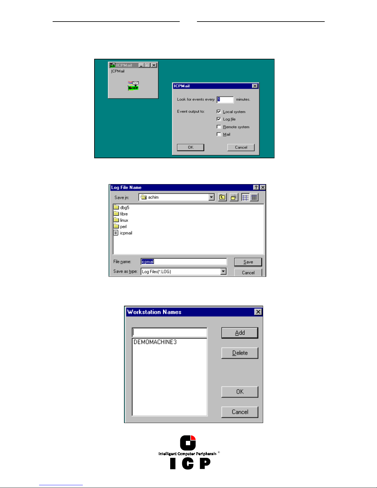
76
The ICP Mail tool gathers messages from the ICP Service, generates standard mail messages and sends them to pre-defined workstations.
After loading ICPMAIL.EXE and selecting "Settings", you can configure the mailing tool.
If you select "Local System" all messages are displayed on the server itself.
If you select "Log file" you are asked for a log file path/name. All messages are recorded into
this file.
"Remote System" allows you to add workstations to which messages are send.
Page 77

77
Following is a typical message generated by ICP Mail.
The "Mail" option allows the interfacing to a standard mailing system (like Microsoft Outlook or Exchange).
 Loading...