

Page 1

DELUXE HIGH WALL MINI SPLIT
SERVICE MANUAL
MODEL : HMC030KD1
HMH030KD1
CAUTION
-BEFORE SERVICING THE UNIT, READ THE "SAFETY
PRECAUTIONS" IN THIS MANUAL.
-ONLY FOR AUTHORIZED SERVICE PERSONNEL.
International Comfort Products
Page 2

- 2 -
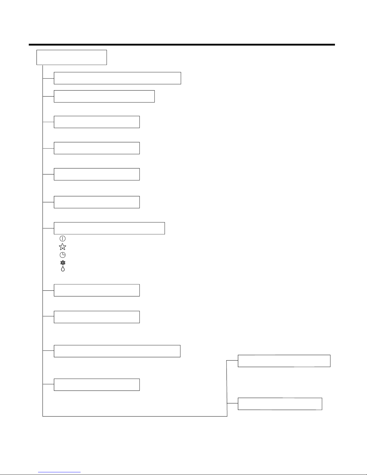
Contents
Functions
.................................................................................................................................3
Product Specifications
..........................................................................................................5
Dimensions
..............................................................................................................................7
Refrigeration Cycle Diagram
..................................................................................................9
Pipe Length and the Elevation.............................................................................................10
Wiring Diagram
......................................................................................................................11
Operation Details
..................................................................................................................13
Display Function
...................................................................................................................20
Self-diagnosis Function
........................................................................................................20
Installation
.............................................................................................................................21
Operation
...............................................................................................................................37
Disassembly of the parts (Indoor Unit)
...............................................................................39
3-way Valve
............................................................................................................................43
Cycle Troubleshooting Guide
...............................................................................................48
Electronic Parts Troubleshooting Guide
.............................................................................49
Electronic Control Device
.....................................................................................................55
Schematic Diagram
...............................................................................................................58
Exploded View and Replacement Parts List
.......................................................................60
Page 3
- 3 -
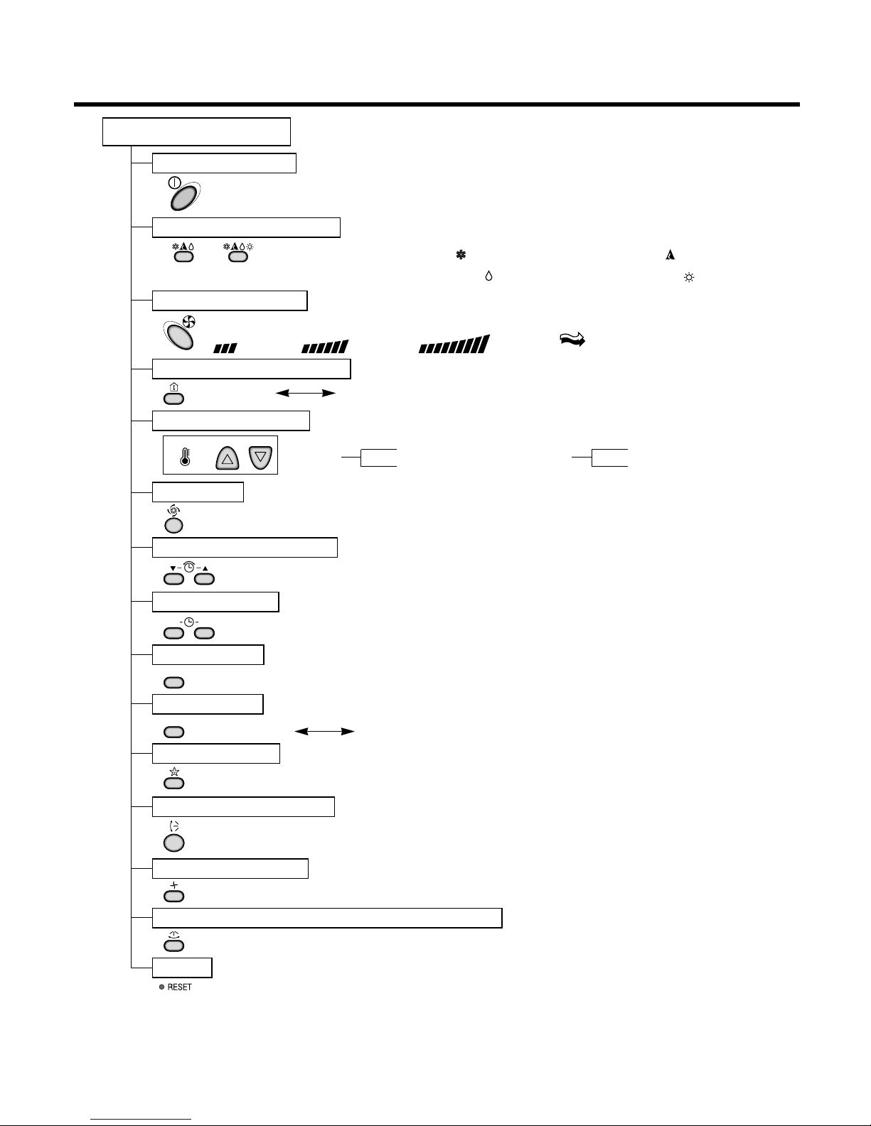
Functions
Indoor Unit
Operation ON/OFF by Remote controller
Sensing the Room Temperature
Room temperature control
Starting Current Control
Time Delay Safety Control
Indoor Fan Speed Control
Operation indication Lamps (LED)
Healthy Dehumidification Mode
Sleep Mode Auto Control
Auto Air Control by the unit electronic control
Chaos Swing
Defrost control(Heating)
Hot-start Control (Heating)
• Room temperature sensor (THERMISTOR)
• Maintains the room temperature in accordance with the Setting Temp.
• Indoor fan is delayed for 5 seconds at the starting.
• Restarting is inhibited for approx. 3 minutes.
• High, Med, Low and Auto
• Intermittent operation of fan at low speed
• Both the indoor and outdoor fan stops
during defrosting.
• Hot start will be operated after
defrosting ends.
• The indoor fan stops until the
indoor pipe temperature will be
reached at 28°C(82°F).
• The fan is switched to low(Cooling), med(Heating) speed.
• The unit will be stopped after 1, 2, 3, 4, 5, 6, 7 hours.
• The fan is switched to intermittent or irregular operation.
• The fan speed is automatically switched from high to low speed.
• The louver can be set at the desired position or swing up
and down automatically.
--- Lights up in operation
--- Lights up in Sleep Mode
--- Lights up in Timer Mode
--- Lights up in Defrost Mode or Hot Start Mode (only Heating Model)
--- Lights up during compressor running (only Cooling Model)
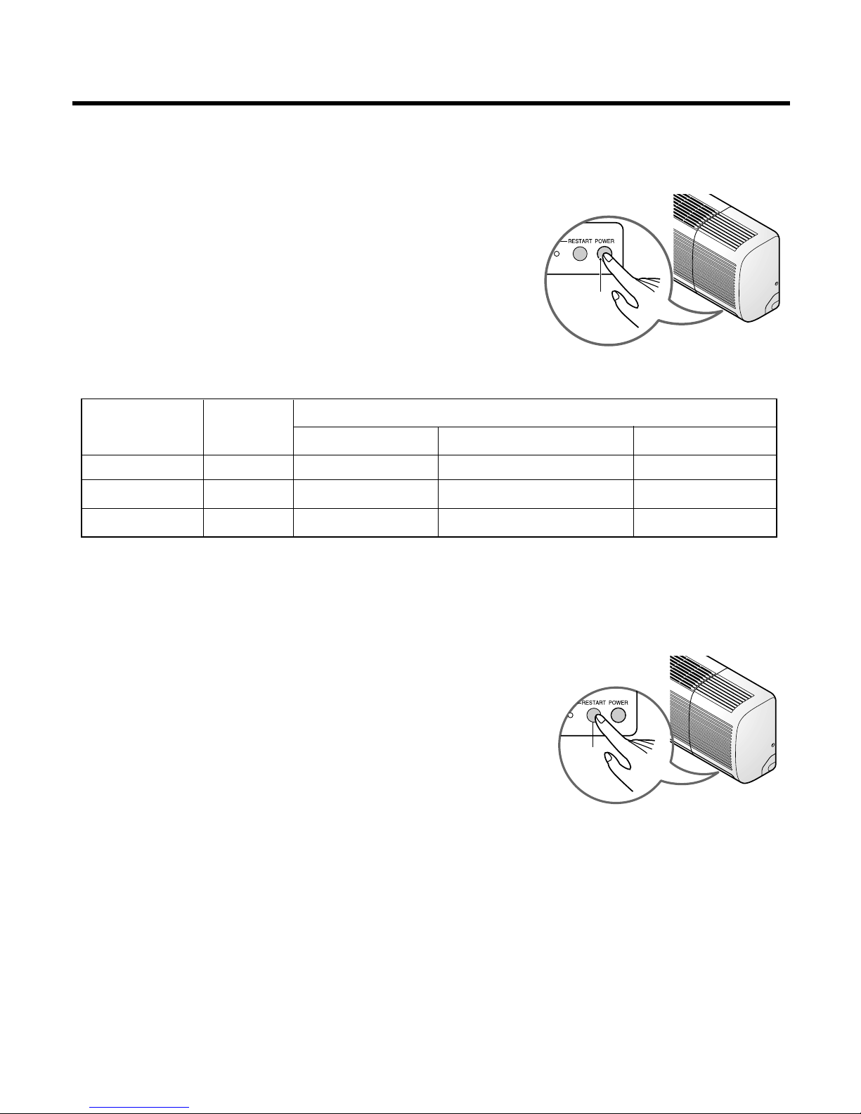
OUT
DOOR
Page 4
- 4 -
Healthy Dehumidification Operation Mode.
( )
Remote Controller
Operation ON/OFF
Reset
Operation Mode Selection
Temperature Setting
Timer Selection
Timer Setting
JET COOL
Timer Cancel
Sleep Operation
Airflow Direction Control
(Cooling
model only)
(Heating
model only)
TEMPERATURE
LOW HIGH
Cooling Operation Mode.( )
Heating Operation Mode.( )
Auto Operation Mode.( )
Fan Operation Mode
Horizontal Airflow Direction Control Button(Option)
Room, Temperature Display
Setting the Time or Timer
ON OFF
SET
CANCEL
Fan Speed Selection
(Low) (Med) (High) (CHAOS)
: (High:39°C Low:11°C)
: OFF, ON, OFF ON
: Cancel Sleep Mode, Timer ON or Timer OFF
: 1, 2, 3, 4, 5, 6, 7, Off Timer
: Fan Operates without cooling or heating.
Cooling
Down to 18°C
Up to 30°C
Heating
Down to 16°C
Up to 30°C
Page 5

- 5 -
Product Specifications(Cooling Only)
* Design and Specifications subject to change without prior notice for product improvement.
Items Unit HMC030KD1
Power Supply ø, V, Hz 230/208,60
Cooling Capacity BTU/h 28,000/27,000
Input W 3,600/3,450
Running Current A 16.0/16.5
COMP. Locked Rotor AMP. A 68
E.E.R BTU/hW 7.81/7.79
Air Circulation m3/min(cfm) 21(740)
Moisture Removal l/h(pts/hr) 3.7(7.8)
Noise Level Indoor, High dB(A) 49
(Sound Med dB(A) 46
Pressure, 1m) Low dB(A) 43
Outdoor, Max dB(A) 63
Features Temperature Control Thermistor
Air Deflection 4-way
Steps, Fan/Cool 3/3
Airflow Direction Control(up&down) Auto
Airflow Direction Control(left&right) Manual
Remocon Type Wireless LCD
Setting Temperature Range, Cooling Mode 64~86°F
Temperature Increment 2°F
Auto Operation(electronic control) Yes
Self Diagnosis Yes
Timer 24hr, On/Of
Sleep Operation Yes
Healthy Dehumidification Mode Yes
Restart Delay minutes 3
Refrigerant(R-22) Charge g(oz) 2550(89.9)
Power cord AWG #: P*mm
2
14:3*2.5
Fuse or breaker Capacity A 30A
Connecting Cable AWG #: P*mm
2
16:4*0.75
Connecting Tube Liquid Side mm(in) 6.35(1/4)
(ø. Socket Flare) Gas Side mm(in) 12.7(1/2)
Length, std m(ft) 7.62(25)
Additional Drain Hose(Outer Dia.) mm(in) 15.5(5/8)
Dimensions Indoor mm 1259*349*205
(WxHxD) in 49.6*13.7*8.1
Outdoor mm 870*800*320
in 34.3*31.5*12.6
Net Weight Indoor kg(lbs) 20
Outdoor kg(lbs) 71
Page 6

- 6 -
Product Specifications(Cooling & Heating)
Items Unit HMH030KD1
Power Supply ø, V, Hz 1,230/208,60
Cooling Capacity BTU/h 28,000/27,000
Heating Capacity BTU/h 29,000/28,000
Input Cooling W 3,600/3,450
Heating W 3,750/3,550
Running Current Cooling A 16.0/16.5
Heating A 16.5/17.0
COMP. Locked Cooling A 68
Rotor AMP. Heating A 68
E.E.R BTU/hW 7.78/7.82
C.O.P 2.26/2.30
Air Circulation m3/min(cfm) 21(740)
Moisture Removal l/h(pts/hr) 3.7(7.8)
Noise Level Indoor, High dB(A) 49
(Sound Med dB(A) 46
Pressure, 1m) Low dB(A) 43
Outdoor, Max dB(A) 63
Features Temperature Control Thermistor
Air Deflection 4-way
Steps, Fan/Cool/Heat 3/3/3
Airflow Direction Control(up&down) Auto
Airflow Direction Control(left&right) Manual
Remocon Type Wireless LCD
Setting Temperature Range, Cooling Mode
64~86°F
Heating Mode 60~86°F
Temperature Increment 2°F
Auto Operation(electronic control) Yes
Self Diagnosis Yes
Timer 24hr, On/Off
Sleep Operation Yes
Healthy Dehumidification Mode Yes
Restart Delay minutes 3
Defrost Control Yes
Hot Start Yes
Refrigerant(R-22) Charge g(oz) 2550(89.9)
Power cord AWG #: P*mm
2
14:3*2.5
Fuse or breaker Capacity A 30A
Connecting Cable AWG #: P*mm
2
18:4*0.75
Connecting Tube Liquid Side mm(in) 9.52(3/8)
(ø. Socket Flare) Gas Side mm(in) 15.88(5/8)
Length, std m(ft) 7.62(25)
Additional Drain Hose(Outer Dia.) mm(in) 15.5(5/8)
Dimensions Indoor mm 1259*349*205
(WxHxD) in 49.6*13.7*8.1
Outdoor mm 770*540*245 870*800*320
in 34.3*31.5*12.6
Net Weight Indoor kg(lbs) 20
Outdoor kg(lbs) 33(72.8) 71
* Design and Specifications subject to change without prior notice for product improvement.
Page 7

(1) Indoor Unit
- 7 -
Dimensions
W
H
Tubing hole cover
Tubing hole cover
Installation plate
D
W
mm(inch)
1,259(49.6)
H
mm(inch)
349(13.7)
D
mm(inch)
205(8.1)
Model
Dimension
30K SERIES
Page 8
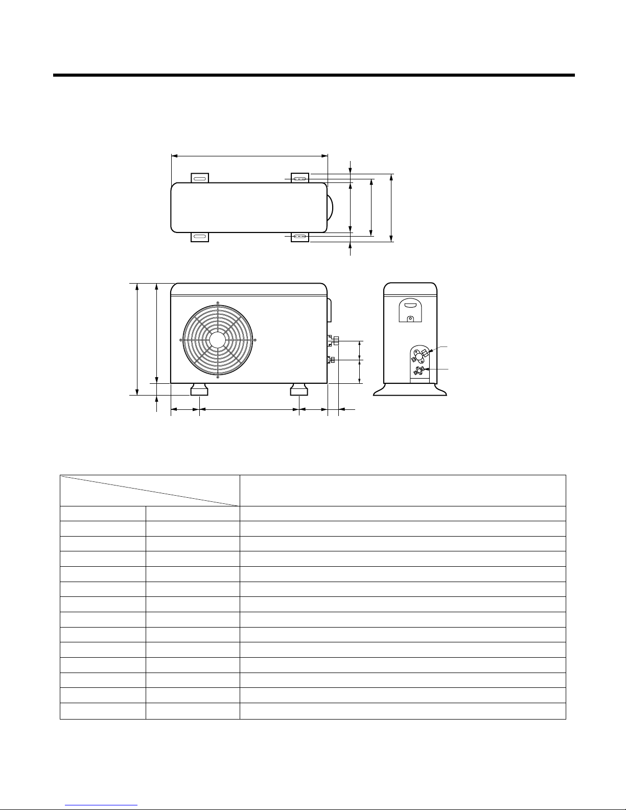
- 8 -
MODEL
DIM
- 8 -
W
L7 L6 L8 L9
D
L1
L2
L3
L10L11
L4L5
H
Gas side
3-way valve
Liquid side
3-way valve
W mm(in ch) 870(34.3)
H mm(in ch) 800(31.5)
D mm(in ch) 320(12.6)
L1 mm(in ch) 370(14.6)
L2 mm(in ch) 340(13.4)
L3 mm(in ch) 25(1.0)
L4 mm(in ch) 775(30.5)
L5 mm(in ch) 25(1.0)
L6 mm(in ch) 546(21.5)
L7 mm(in ch) 162(6.4)
L8 mm(in ch) 162(6.4)
L9 mm(in ch) 54(2.1)
L10 mm(in ch) 74.5(2.9)
L11 mm(in ch) 79(3.1)
30K SERIES
(2) Outdoor Unit
Page 9
- 9 -
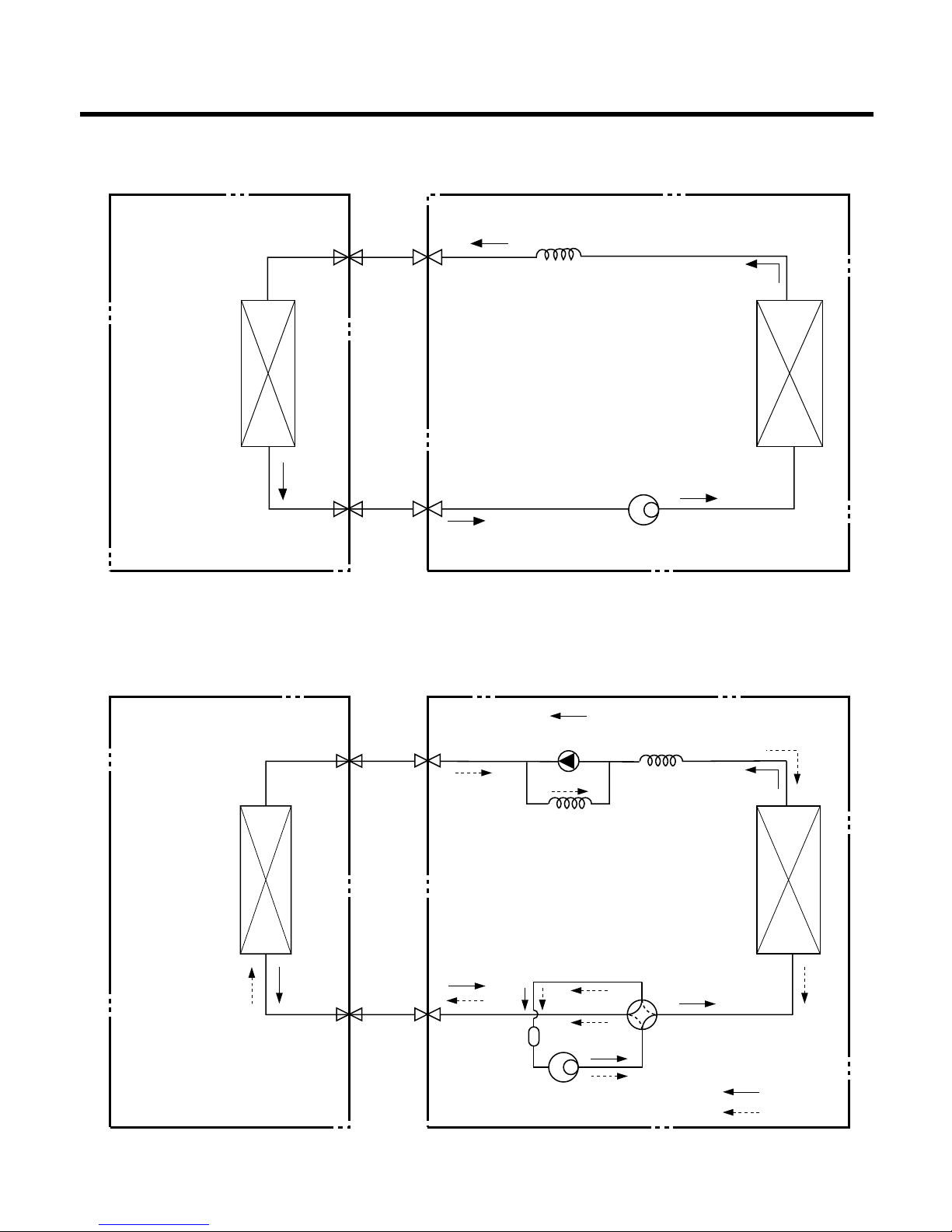
Refrigeration Cycle Diagram
INDOOR UNIT OUTDOOR UNIT
INDOOR UNIT OUTDOOR UNIT
HEAT
EXCHANGER
(EVAPORATOR)
HEAT
EXCHANGER
(EVAPORATOR)
HEAT
EXCHANGER
(CONDENSER)
HEAT
EXCHANGER
(CONDENSER)
COMPRESSOR
COMPRESSOR
ACCUMU
LATOR
Suction Line
Suction Line
3-WAY VALVE
Evaporator Line
Evaporator Line
3-WAY VALVE
CAPILLARY TUBE
CAPILLARY TUBE
CHECK VALVE
(Heating Model only)
COOLING
HEATING
REVERSING
VALVE
(Heating Model Only)
(1) Cooling Only Models
(2) Cooling & Heating Models
Page 10
- 10 -
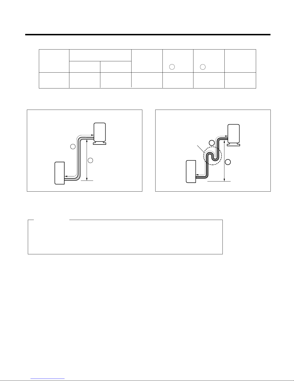
Pipe length and the elevation
* Capicity is based on standard length and maximum allowance length is the basis of
reliability.
* Oil trap should be installed per 5~7 meters(16.4~23.0ft).
CAUTION
Outdoor unit
Indoor unit
A
B
A
Oil trap
Outdoor unit
Indoor unit
B
In case more than 5m (16.4ft)
30k
5/8" 3/8" 7.5(25) 15(50) 30(100) 30(0.32)
(50Hz, 60Hz)
Pipe Size
Capacity
(Btu/h)
GAS LIQUID
Additional
Refrigerant
g/m(oz/ft)
Max.
Length
A m(ft)
Max.
Elevation
B m(ft)
Standard
Length
m(ft)
Page 11
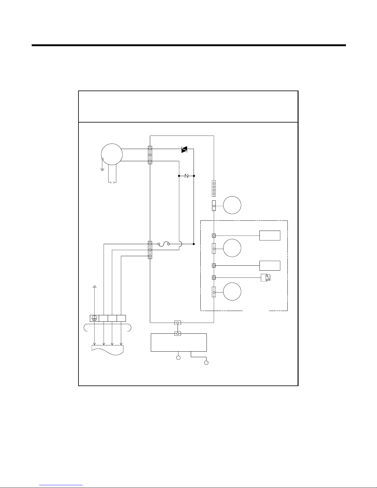
- 11 -
Wiring Diagram
(1) Indoor Unit (Cooling Only Models, & Heating Models)
MOT OR
SH-CAPA.
YL
PILLAR
TERMINAL
AUTO RESTART
FORCED OPERATION
CN-DISP
CN-L/R CN-U/D CN-TH
THERMISTOR
STEP
MOTOR
(UP/DOWN)
STEP
MOTOR
(L/R)
H.V.B ASM
LIMITS S/W
Negative ion
OPTION
STEP
MOTOR
(L/R)
CN-L/R
DISPLAY PCB ASM
3854A20065A
TO OUTDOOR UNIT
BL
3(L)
4(N) 5
BR
GN/YL
BL
RD RD
BR
GN/YL
BR
FUSE
AC250V/T2A
TRIAC
OR
BK
ZNR
CN-POWER
CN-MOTOR
WIRING DIAGRAM
Page 12
- 12 -
(2) Outdoor Unit
• Cooling Only Models
• Heating Models
TO INDOOR
UNIT
POWER
INPUT
FMo
T/B
Comp(B)
OLP
CAPACITOR(B)
CAPACITOR(A)
C
C
S
S
R
R
Comp(A)
5
RD
BL
BR
BK
YL
YL BR
BL BK
RD
RD
BL
BK
BKBKOR
OR
GN/YL
BL
BR
FUSE
(250V,5A)
FUSE
(250V,5A)
FUSE(250V,3A)
CN-POWER
CN-FAN
CN-CON
CN-COMP
H
HCCF
CN-LEV
CN-TH2
PIPE-IN
TEMP-IN
COIL EXPANSION
RY-HI
RY-COMP(B)
RY-COMP(A)
3(L1)
2(L2)
4(L2)
1(L1)
MAIN
PCB ASM
3854A20153W
WIRING DIAGRAM
Page 13
- 13 -
(1) The function of main control
1. Time delay Safety Control
• 3min.; The compressor operation is delayed for 3 minutes to balance the pressure of cycle.
(Protection of compressor)
• 5sec.;
The indoor fan is delayed for 5 seconds, when operating initially, to prevent noises occurred by the vertical
louver and wind.
• 2min.; The reversing valve is delayed for 2 minutes to prevent the refrigerant-gas for abnormal noise when the
heating operation is OFF or switched to the other operation mode while compressor is off.
While compressor is running, it takes 3~5 seconds to switch.
2. Chaos Swing Mode
• By the Chaos Swing key input, the upper/lower vane automatically operates with the Chaos Swing or they are
fixed to the desired direction.
• While in Chaos Swing mode, the angles of cooling and heating cycle operations are different.
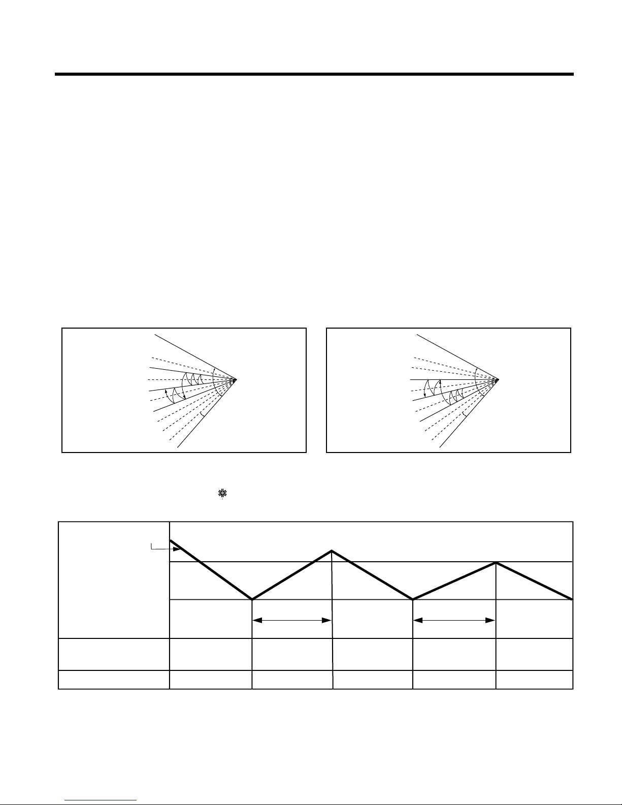
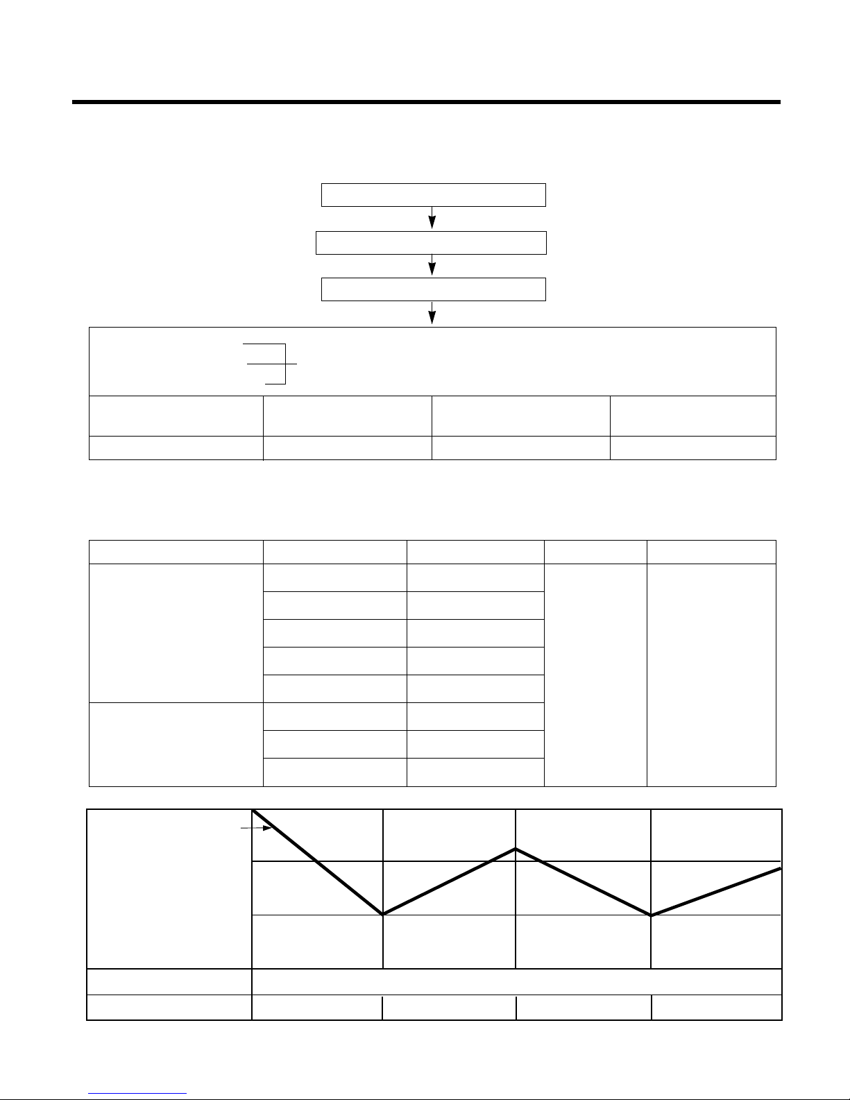
Operation Details
INTAKE AIR TEMP.
SETTING TEMP. +1°F
(Compressor ON)
SETTING TEMP. -1
°
F
(Compressor OFF)
Setting
fan speed
Setting
fan speed
More than
3 minutes
More than
3 minutes
Setting
fan speed
COMPRESSOR ON OFF ON OFF ON
INDOOR FAN SPEED Low Low
■ Protection of the indoor heat exchanger from frosting
• Compressor and outdoor fan stop when indoor pipe temperature is below 0°C(32°F) and restart at the pipe
temperature is above 7°C(45°F).
3. Cooling Operation Mode
• When selecting the Cooling( ) Mode Operation, the unit will operate according to the setting by the
remote control and the operation diagram is shown below.
CLOSED
OPEN
< Cooling Mode >
8°
CLOSED
OPEN
< Heating Mode >
8°
Page 14
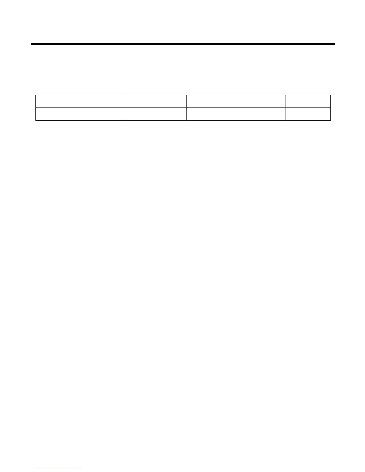
. Auto Operation (Electronic control mode)
• The operation procedure is shown below. (Cooling & Heating Model)
❋ If initial mode is decided, that mode is continued without the room temperature changing.
■ Auto Operation for Cooling
- 14 -
Press Start/Stop Button
Select Auto Operation Mode
Check the Room temperature
Operation mode
Indoor fan speed are decided automatically by the unit electronic control.
Setting temperature
Intake-air
temperature
Operation Mode
Over below
70°F76
°
F
Soft Dry
below 70°F
Heating
Over 76°F
Cooling
~
INTAKE AIR TEMP.
SETTING TEMP. +1°F
(Compressor OFF)
SETTING TEMP. -1°F
(Compressor ON)
COMPRESSOR ON OFF ON OFF
INDOOR FAN SPEED The electronic control operation
Intake-air Temperature Setting Temperature
Over 78°F77°F
Over 76°F~below 78°F Intake air -1°C
Over 72°F~below 76°F Intake air -0.5°C
Over 68°F~below 72°F Intake air temperature
below 64°F64°F
Over 64°F~below 86°F Electronic control
below 64°F64°F
over 86°F86°F
Operation Condition
When Auto Operation
initial start
Controlled by
the electronic
control
In this mode,
when pressing
the vertical air
direction control
button, vertical
louver swings up
and down
automatically.
Fan Speed Air Direction Control
When pressing room
temperature setting
button during Auto
Operation
Page 15
- 15 -
■ Auto Operation for Dehumidification(only Heating Model)
• The Setting temperature will be same that of the auto operation for cooling.
- Compressor ON temperature; Setting temperature +2°F
- Compressor OFF temperature; Setting temperture -1°F
■ Auto Operation for Heating(only Heating Model)
- Compressor ON temperature; Setting temperature
- Compressor OFF temperature; Setting temperature +6°F
Intake-air temp. below 68°F Over 68°F~below 70°F over 86°F
Setting temp. 68°F Intake air temperature +1°F86°F
■ Vertical louver auto operation
: During Auto Operation, pressing the chaos swing button makes the horizontal louvers swing up and down automatically.
If you want to stop auto-swing, press chaos swing button again.
Page 16

- 16 -
5. Healthy Dehumidification
• When the dehumidification operation input by the remote control is received, the intake air temperature is
detected and the setting temp is automatically set according to the intake air temperature.
26°C ≤ Intake Air Temp ➲ 25°C
24°C ≤ Intake Intake Air Temp<26°C ➲ Intake Air Temp-1°C
18°C ≤ Intake Intake Air Temp<24°C ➲ Intake Air Temp-0.5°C
Intake Air Temp<18°C ➲ 18°C
• While in compressor off, the indoor fan repeats low airflow speed and pause.
• While the intake air temp is between compressor on temp. and compressor off temp., 10-min dehumidification
operation and 4-min compressor off repeat.
Compressor ON Temp. ➲ Setting Temp+0.5°C
Compressor OFF Temp. ➲ Setting Temp-0.5°C
• In 10-min dehumidification operation, the indoor fan operates with the low airflow speed.
Page 17
- 17 -
6. Heating Operation Mode(only Heating Model)
The unit will operate according to the setting conditions by the remote controller.
The operation diagram is shown below.
INTAKE AIR TEMP.
SETTING TEMP. +6
°
F
(Compressor OFF)
SETTING TEMP.
(Compressor ON)
Selecting
fan speed
Selecting
fan speed
A
B
A
minimum
10sec.
minimum
1 min.
minimum
10sec.
COMPRESSOR ON OFF ON OFF
• A point; While the indoor pipe temperature is higher than 95°F, indoor fan operates at low speed. When the
indoor pipe temperature becomes lower than 95°F, indoor fan stops.
• B point; When the indoor pipe temperature is higher than 38°C(100°F), fan operates at selected fan speed.
INDOOR FAN SPEED
Low
OFF
Low Low OFF
OFF OFFLOW
ON
Selecting
fan speed
INDOOR PIPE
TEMP.
82°F
78°F
1min
INDOOR FAN SPEED
COMPRESSOR
■ Hot-Start Control
• The indoor fan stops until the indoor pipe temperature will be reached at 82°F.
• During heating operation, if indoor pipe temperature falls below 78°F fan stops.
• The operation diagram is shown below.
Page 18
- 18 -
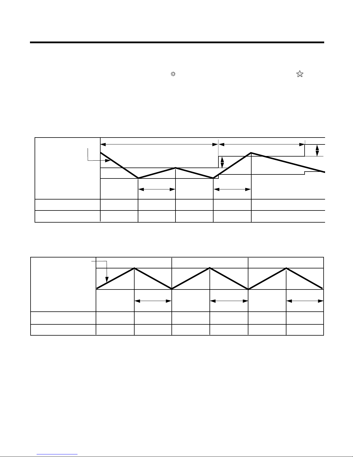
7. Cooling or Heating Mode with Sleep Mode Auto Control
• When selecting the Cooling( ) or the Heating( ) combined with the Sleep Mode Auto Control( ), the
operation diagram is as following.
■ Cooling Mode with the Sleep Mode
• The setting temperature will be automatically raised by 2°F 30 minutes later and by 4
°
F 1 hour later.
• The operation will be stopped after 1, 2, 3, 4, 5, 6, 7 hours.
■ Heating Mode with the Sleep Mode(only Heating Model)
• The operation will be stopped after 1, 2, 3, 4, 5, 6, 7 hours.
INTAKE AIR TEMP.
SETTING TEMP. +1°F
(Compressor ON)
SETTING TEMP. -1°F
(Compressor OFF)
30 minutes
30 minutes
More than
3 minutes
2°F
2°F
More than
3 minutes
COMPRESSOR ON OFF ON OFF ON
INDOOR FAN SPEED Low Low Low Low Low
SETTING TEMP. +6
°
F
(Compressor OFF)
SETTING TEMP.
(Compressor ON)
COMPRESSOR ON OFF ON OFF ON OFF
INDOOR FAN SPEED Med Low or OFF Med Low or OFF Med Low or OFF
INTAKE AIR TEMP.
More than
3 minutes
More than
3 minutes
More than
3 minutes
Page 19
- 19 -
8. Forced Operation
To operate the appliance by force in case that the remote controller is
lost, the forced operation button is on the main unit of the appliance to
operate the appliance in the standard conditions.
• Press the forced operation button, the forced operation is carried out.
• Press the forced operation button once again to stop operation.
In case the power comes on again after power failure on the Forced
Operation position, the operating conditions are automatically set as follows:
During Forced Operation, the initial mode continues.
9. AUTO RESTART
In case the power comes on again after a power failure, Auto Restarting
Operation is the function to operate procedures automatically to the previous operating conditions.
If you want to use this operation. The autorestart button is on the main
unit of the appliance in the standard condition.
• press the auto restart button, to make this function active.
• If you do not want to use this operation, free the auto restart button
once again.
If you do not want to use this operation, move the Slide Switch to the
Remote Control position.
Cooling Heat pump Model
Model
Room Temp. ≥ 24°C(76°F)
21°C(70°F) ≤ Room Temp. < 24°C(76°F)
Room Temp. < 21°C(70°F)
Operating mode Cooling Cooling Healthy Dehumidification Heating
Indoor FAN Speed
High High
Healthy Dehumidification Rule
High
Setting Temperature
22°C(72°F) 22°C(72°F) 23°C(74°F) 24°C(76°F)
FORCED
FORCED
OPERATION
OPERATION
FORCED
OPERATION
AUTO
RESTART
AUTO
RESTART
FORCED
OPERATION
Page 20
- 20 -
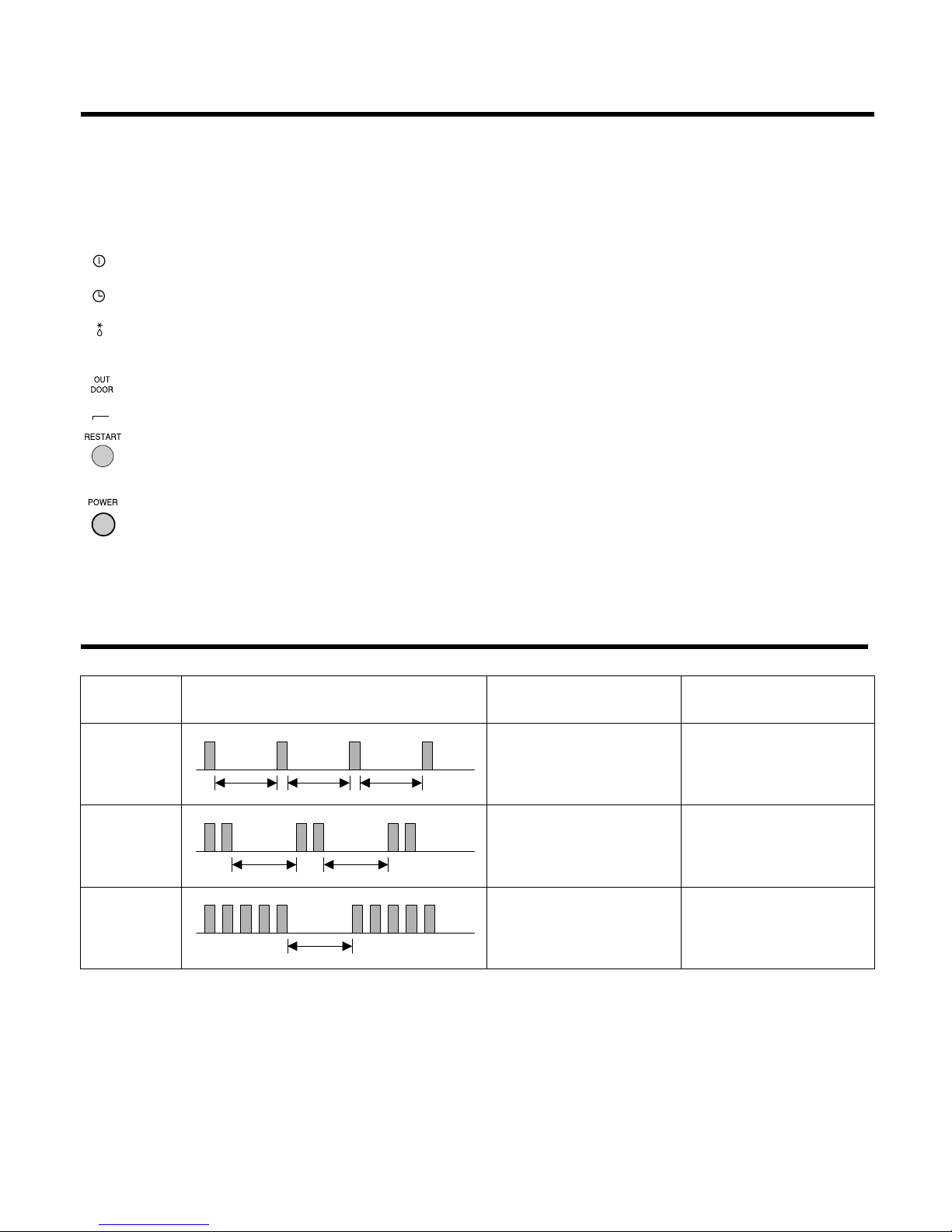
Display Function
Self-diagnosis Function
Signal Receptor
Receives the signals from the remote control.(Signal receiving sound: two short beeps or one long beep.)
Operation Indication Lamps
On/Off : Lights up during the system operation.
Timer or Sleep Mode : Lights up during Timer operation or Sleep mode.
Defrost Mode : Lights up during Defrost Mode or Hot
Start operation. (Heat pump model only)
Outdoor unit operation : Lights up during outdoor unit operation. (Cooling model only)
Auto Restart Mode : Lights up during if Restart Button is pressed.
Auto Restart Button : In failure of electric power, if the button is pressed the unit runs as previous
setting operation when power returns.
Forced Operation Button
: Operation starts, when this button is pressed and stops when you press the
button again.
3sec 3sec 3sec
(once)
3sec 3sec
(twice)
3sec
(5times)
Error
Code
1
2
5
Error LED
(Indoor body operation LED)
Error contents
• Indoor room temperature
thermistor open/short
• Indoor pipe temperature
thermistor open/short.
• Outdoor pipe temperature
thermistor open/short.
• Poor communication.
• Indoor TH assy check
• Outdoor TH assy check
• Communication line/circuit
check
SVC check point
Page 21

- 21 -
Installation
Read completely, then follow step by step.
1. Installation of Indoor,
Outdoor unit
Installation Parts Provided
1) Select the best location
1. Indoor unit
■ Do not have any heat or steam near the unit.
■ Select a place where there are no obstacles in front
of the unit.
■ Make sure that condensation drainage can be conveniently routed away.
■ Do not install near a doorway.
■ Ensure that the space around the left and right of
the unit is more than 30cm(12"). The unit should be
installed as high on the wall as possible, allowing a
minimum of 12cm(4.8") from ceiling.
■ Use a stud finder to locate studs to prevent unnecessary damage to the wall.
2. Outdoor unit
■
If an awning is built over the unit to prevent direct sunlight or
rain exposure, make sure that heat radiation from the condenser is not restricted.
■
Ensure that the space around the back and sides is more than
10cm(4"). The front of the unit should have more than
70cm(28") of space.
■
Do not place animals and plants in the path of the warm air.
■
Take the air conditioner weight into account and select a place
where noise and vibration are minimum.
■
Select a place so that the warm air and noise from the air conditioner do not disturb neighbors.
■ Rooftop Installations:
If the outdoor unit is installed on a roof structure, be
sure to level the unit. Ensure the roof structure and
anchoring method are adequate for the unit location.
Consult local codes regarding rooftop mounting.
If the outdoor unit is installed on root structures or walls,
this may result in excessive noise and vibration, and
maybe also classed as non serviceable installation.
2) Piping length and elevation
More than
12cm(4.8")
More than
30cm(12")
More than
30cm(12")
More than 2.3m(7.5ft)
More than
10cm(4")
More than
10cm(4")
More than
60cm(24")
More than
60cm(24")
More than
70cm(28")
In case more than 5m(16.4ft)
• Capacity is based on standard length and maximum
allowance length is on the basis of reliability.
• Oil trap should be installed In case more than 5~7meters
(16.4~23.0ft).
Outdoor unit
Indoor unit
A
B
A
Oil trap
Outdoor unit
Indoor unit
B
CAUTION
Install the indoor unit on the wall where the height
from the floors more than 2.3meters(7.5ft).
A minimum pipe run of 7.5meters(25ft) is required to
minimise vibration & excessive noise.
CAUTION
30k 5/8" 3/8" 7.5(25) 15(50) 30(100)
30(1.102
)
Pipe Size
Capacity
(Btu/h)
GAS LIQUID
Max.
length
A m(ft)
Additional
Refrigerant
g/m(oz/ft)
Max.
Elevation
B m(ft)
Standard
Length
m(ft)
1. Type "A" screw
2. Installation Plate
3. Type "B" screw
4. Holder Remote Control
Page 22

- 22 -
3) How to fix installation plate
The wall you select should be strong and solid enough to prevent
vibration
1. Mount the installation plate on the wall with four
type A screws. If mounting the unit on a concrete
wall, use anchor bolts.
Mount the installation plate horizontally by
aligning the centerline using a level.
2. Measure the wall and mark the centerline. It is also
important to use caution concerning the location
of the installation plate-routing of the wiring to
power outlets is through the walls typically.
Drilling the hole through the wall for piping connections must be done safely.
5-7mm
(0.2~0.3")
Indoor
WALL
Outdoor
Installation Plate
Type "A" screw
(+1 D4.0 L38.0 MSR3/FZW)
30K
Right rear pipingLeft rear piping
50mm(2.0")
ø
70mm(2.76")180mm
(7.2")
115mm(4.5in)
4) Drill a hole in the wall
■ Drill the piping hole with a ø70mm (0.76") hole
core drill. Drill the piping hole at either the right or
the left with the hole slightly slanted to the outdoor side.
Page 23

- 23 -
1) Flaring work
Main cause for gas leakage is due to defect in flaring work. Carry out correct flaring work in the following procedure.
1. Cut the pipes and the cable.
■ Use the piping kit accessory or the pipes
purchased locally.
■ Measure the distance between the indoor and the
outdoor unit.
■ Cut the pipes a little longer than measured
distance.
■ Cut the cable 1.5m(59.1") longer than the pipe
length.
2. Burrs removal
■ Completely remove all burrs from the cut cross
section of pipe/tube.
■ Put the end of the copper tube/pipe in a downward direction as you remove burrs in order to
avoid dropping burrs into the tubing.
3. Putting nut on
■ Remove flare nuts attached to indoor and outdoor
unit, then put them on pipe/tube having completed burr removal.
(not possible to put them on after flaring work)
Copper
pipe
90°
Slanted Uneven Rough
Bar
Copper pipe
Clamp handle
Red arrow mark
Cone
Yoke
Handle
Bar
"A"
Pipe
Reamer
Point down
4. Flaring work
■ Carry out flaring work using flaring tool as shown
below.
Firmly hold copper pipe in a die in the dimension
shown in the table above.
5. Check
■ Compare the flared work with figure below.
■ If flare is noted to be defective, cut off the flared
section and do flaring work again.
mm inch mm
ø6.35 1/4 0 ~ 0.5
ø9.52 3/8 0 ~ 0.5
ø12.7 1/2 0 ~ 0.5
ø15.88 5/8 0 ~ 1.0
Outside diameter A
Flare nut
Copper tube
Inclined
Inside is shiny without scratches
Smooth all round
Even length
all round
Surface
damaged
Cracked Uneven
thickness
= Improper flaring =
2. Flaring Work and Connection of Piping
Page 24

- 24 -
2) Connection of piping-Indoor
1. Remove the 2 screws of right side panel.
2. Remove the front right side panel by the arrow.
■ The connector can be disconnected by pulling it
while pressing the connector's hook.
■ Remove the 1 screw for fixing lower panel.
3. Remove the lower panel by the arrow.
■ Take care not to scratch the wall and mat to
drop.
1. Route the indoor tubing and the drain hose in the
direction of rear left.
2. Insert the connecting cable into the indoor unit
from the outdoor unit through the piping hole.
■ Do not connect the cable to the indoor unit.
■ Make a small loop with the cable for easy
connection later.
Right side panel
Drain hose
Main PCB
Lower panel
Lower panel
For left rear piping
CAUTION
When install, make sure that the
remaining parts must be
removed clearly so as not to
damage the piping and drain
hose, especially power cord and
connecting cable.
Page 25

- 25 -
3. Tape the tubing, drain hose and the connecting
cable. Be sure that the drain hose is located at the
lowest side of the bundle. Locating at the upper side
can cause drain pan to overflow inside the unit.
3. Tape the tubing, drain hose and the connecting
cable. Be sure that the drain hose is located at the
lowest side of the bundle. Locating at the upper side
can cause drain pan to overflow inside the unit.
NOTE: If the drain hose is routed inside the room,
insulate the hose with an insulation material*
so that dripping from "sweating"(condensation) will not damage furniture or floors.
*Foamed polyethylene or equivalent is rec-
ommended.
4. Indoor unit installation
■ Hook the indoor unit onto the upper portion of the
installation plate.(Engage the three hooks of the
rear top and rear lower of the indoor unit with the
upper edge and lower edge of the installation
plate.) Ensure that the hooks are properly seated
on the installation plate by moving it left and right.
5. Connecting the pipings to the indoor unit and drain
hose to drain pipe.
■ Align the center of the pipings and sufficiently
tighten the flare nut by hand.
■ Tighten the flare nut with a wrench.
■ When extending the drain hose at the indoor unit,
install the drain pipe.
Connecting
cable
Loop
Gas side
piping
Liquid side
piping
Drain hose
Installation
plate
Three upper
hooks
Installation plate
Indoor unit
Three lower
hooks
Setting line
Indoor unit tubing Flare nut Pipings
Connection pipe
Flare nut
Indoor unit tubing
Torque wrench
Spanner (fixed)
Vinyl tape(narrow)
Adhesive
Drain pipe
Indoor unit drain hose
Pipe Size[Torque]
Capacity
(Btu/h)
Suction Evaporator
30K 5/8"[6.6kg.m] 3/8"[4.2kg.m]
Page 26

- 26 -
6. Wrap the insulation material around the connecting
portion.
■
Overlap the connection pipe insulation material and
the indoor unit pipe insulation material. Bind them
together with vinyl tape so that there is no gap.
■ Wrap the area which accommodates the rear piping housing section with vinyl tape.
■ Bundle the piping and drain hose together by
wrapping them with vinyl tape over the range within which they fit into the rear piping housing section.
1. Route the indoor tubing and the drain hose to the
required piping hole position.
2. Insert the piping, drain hose and the connecting
cable into the piping hole.
3. Insert the connecting cable into the indoor unit.
■ Don't connect the cable to the indoor unit.
■ Make a small loop with the cable for easy
connection later.
4. Tape the drain hose and the connecting cable.
• Connecting cable
Plastic bands
Insulation material
Drain hose
Drain pipe
Connecting cable
Vinyl tape(narrow)
Connection
pipe
Connecting cable
Vinyl tape
(wide)
Wrap with vinyl tape
Indoor
unit pipe
Pipe
Wrap with vinyl tape
Drain hose
Pipe
Vinyl tape(wide)
For right rear piping
Page 27

- 27 -
5. Indoor unit installation
■ Hook the indoor unit onto the upper portion of the
installation plate.(Engage the three hooks of the
rear top and rear lower of the indoor unit with the
upper edge and lower edge of the installation
plate.) Ensure that the hooks are properly seated
on the installation plate by moving it left and right.
6. Connecting the pipings to the indoor unit and the
drain hose to drain pipe.
■ Align the center of the pipings and sufficiently
tighten the flare nut by hand.
■ Tighten the flare nut with a wrench.
■ When extending the drain hose at the indoor unit,
install the drain pipe.
7. Wrap the insulation material around the connecting
portion.
■
Overlap the connection pipe heat insulation and the
indoor unit pipe heat insulation material. Bind them
together with vinyl tape so that there is no gap.
■ Wrap the area which accommodates the rear
piping housing section with vinyl tape.
Installation
plate
Three upper
hooks
Installation plate
Indoor unit
Three lower
hooks
Setting line
Vinyl tape
Adhesive
Drain hose
Indoor unit drain hose
(narrow)
Plastic bands
Insulation material
Vinyl tape(narrow)
Connection
pipe
Connecting cable
Indoor
unit piping
Pipe
Vinyl tape
(wide)
Wrap with vinyl tape
Indoor unit tubing Flare nut Pipings
Torque wrench
Indoor unit tubing
Spanner (fixed)
Connection pipe
Flare nut
Pipe Size[Torque]
Capacity
(Btu/h)
Suction Evaporator
30K 5/8"[6.6kg.m] 3/8"[4.2kg.m]
Page 28

- 28 -
■ Bundle the piping and drain hose together by
wrapping them with cloth tape over the range
within which they fit into the rear piping housing
section.
8. Reroute the pipings and the drain hose across the
back of the chassis.
9. Reinstall the parts to the original position.
■ Refix the lower panel to the original position.
■ Connect display conductor.
■ Refix the front right side panel to the original
position with the two screws.
Drain hose
Vinyl tape(narrow)
Pipe
Wrap with
vinyl tape(wide)
Lower panel
Main PCB
Piping for
passage through
piping hole
Page 29

- 29 -
3) Connection of the drain hose
■ The drain hose can be connected at two different
positions. Use the most convenient position and, if
necessary, exchange the position of the drain
pan, rubber cap and the drain hose.
➊ Drain pan
➋ Rubber cap
➌ Drain hose
➍ Exchange if necessary
■ Remove the drain hose.
■ Securely insert both the rubber plug and drain
hose into the drain outlets.
Be sure the rubber the cap is securely fastened
so that there is no leakage.
4) Connection of piping-Outdoor
1. Align the center of the pipings and sufficiently
tighten the flare nut by hand.
2. Finally, tighten the flare nut with torque wrench
until the wrench clicks.
■ When tightening the flare nut with torque wrench,
ensure the direction for tightening follows the
arrow on the wrench.
1
2
3
4
Outdoor unit
Gas side piping
(Bigger diameter)
Liquid side
piping
(Smaller
diameter)
Torque wrench
Pipe Size[Torque]
Capacity
(Btu/h)
Suction Evaporator
30K 5/8"[6.6kg.m] 3/8"[4.2kg.m]
Page 30

- 30 -
3. Connecting the cable between
indoor unit and outdoor unit
1) Connect the cable to the indoor unit by
connecting the wires to the terminals on
the control board individually according to
the outdoor unit connection. (Ensure that
the color of the wires of the outdoor unit and
the terminal No. are the same as those of the
indoor unit.)
REDBLUE
BROWN
4(L2)
Terminals on the indoor unit
3(L1)
5
4(L2)
Terminals on the outdoor unit
Color of Wires
POWER INPUT
Color of Wires
3(L1)2(L2)1(L1)
5
G/Y
REDBLUE
BROWN
G/Y
CAUTION
Ø 8.5mm
(0.33in)
20mm
(0.79in)
GN/YL
AWG #12
20mm
(0.79in)
GN/YL
AWG #20
The power supply cord connected to the outdoor
unit should be complied with the following
specifications (UL and CSA recognized one).
The connecting cable connected to the indoor
and outdoor unit should be complied with the
following specifications (UL and CSA
recognized one).
Ø 7.5mm
(0.30in)
Wiring must be as following diagram.
CAUTION
Outdoor
unit
Indoor
unit
Main power source
61cm max
(24 in max)
61cm max
(24 in max)
Outdoor Disconnect Switch
• Must be rated for 30 amps
Disconnect Switch (Optional)
• May be required by local codes
• Must be rated for 15 amps
Page 31

- 31 -
2) Connect the cable to the outdoor unit
1. Remove the control cover from the unit by loosening the screw.
Connect the wires to the terminals on the control
board individually.
2. Secure the cable onto the control board with the
cord clamp.
3. Refix the control cover to the original position with
the screw.
4. Use a recognized circuit breaker 30A (30k, 32k),
35A (36k, 38k) between the power source and the
unit. A disconnecting device to adequately disconnect all supply lines must be fitted.
Terminal block
Over 5mm
Cover control
Connecting cable
The power
connecting cable
After the confirmation of the above conditions, prepare the wiring as follows:
1) Never fail to have an individual power circuit specifically for the air conditioner. As for the method
of wiring, be guided by the circuit diagram posted on the inside of control cover.
2) The screw which fasten the wiring in the casing of electrical fittings are liable to come loose from
vibrations to which the unit is subjected during the course of transportation. Check them and make
sure that they are all tightly fastened. (If they are loose, it could cause burn-out of the wires.)
3) Specification of power source.
4) Confirm that electrical capacity is sufficient.
5) See to that the starting voltage is maintained at more than 90 percent of the rated voltage marked
on the name plate.
6) Confirm that the cable thickness is as specified in the power source specification.
(Particularly note the relation between cable length and thickness. (Refer to page 30))
7) Always install an earth leakage circuit breaker in a wet or moist area.
8) The following would be caused by voltage drop.
• Vibration of a magnetic switch, which will damage the contact point, fuse breaking, disturbance of the nor-
mal function of the overload.
9) The means for disconnection from a power supply shall be incorporated in the fixed wiring and
have an air gap contact separation of at least 3mm in each active(phase) conductors.
CAUTION
Outdoor Unit
30K
Page 32

- 32 -
1) Checking the drainage
1. Remove the right side panel.
2. Remove the lower panel by the arrow.
3. Remove the left side panel.
(Remove the two screws.)
4. To check the drainage.
■ Pour a glass of water on the drain pan.
■ Ensure the water flows through the drain hose of
the indoor unit without any leakage and goes out
the drain exit.
5. Drain piping
■ The drain hose should point downward for easy
drain flow.
■ Do not make drain piping.
Right side panel
Downward slope
Do not raise
Accumulated
drain water
Tip of drain hose
dipped in water
Air
Waving
Water
leakage
Water
leakage
Ditch
Less than
50mm gap
Water
leakage
Lower panel
Left side panel
Page 33

- 33 -
2) Form the piping
1. Form the piping by wrapping the connecting portion of the indoor unit with insulation material and
secure it with two kinds of vinyl tapes.
■ If you want to connect an additional drain hose,
the end of the drain outlet should be routed above
the ground. Secure the drain hose appropriately.
2. In cases where the outdoor unit is installed below
the indoor unit perform the following.
■ Tape the piping, drain hose and connecting cable
from down to up.
■ Secure the tapped piping along the exterior wall
using saddle or equivalent.
3. In cases where the Outdoor unit is installed above
the Indoor unit perform the following.
■ Tape the piping and connecting cable from down
to up.
■ Secure the taped piping along the exterior wall.
Form a trap to prevent water entering the room.
■ Fix the piping onto the wall by saddle or equivalent.
Taping
Drain
hose
Pipings
Connecting
cable
Trap is required to prevent water
from entering into electrical parts.
Seal small openings
around pipings with a
gum type sealer.
Seal a small opening
around the pipings
with gum type sealer.
Trap
Trap
30K
30K
Page 34

- 34 -
4. AIR PURGING
1) Air purging
Air and moisture remaining in the refrigerant system
have undesirable effects as indicated below.
■ Pressure in the system rises.
■ Operating current rises.
■ Cooling(or heating) efficiency drops.
■ Moisture in the refrigerant circuit may freeze and
block capillary tubing.
■ Water may lead to corrosion of parts in the refrigeration system.
Therefore, the indoor unit and tubing between the
indoor and outdoor unit must be leak tested and
evacuated to remove any noncondensables and
moisture from the system.
2) Air purging with vacuum pump
1. Preparation
■ Check that each tube(both liquid and gas side
tubes) between the indoor and outdoor units have
been properly connected and all wiring for the test
run has been completed. Remove the service
valve caps from both the gas and the liquid side
on the outdoor unit. Note that both the liquid and
the gas side service valves on the outdoor unit
are kept closed at this stage.
2. Leak test
■ Connect the manifold valve(with pressure gauges)
and dry nitrogen gas cylinder to this service port
with charge hoses.
■
Pressurize the system to no more than 150 P.S.I.G.
with dry nitrogen gas and close the cylinder valve
when the gauge reading reached 150 P.S.I.G.
Next, test for leaks with liquid soap.
■ Do a leak test of all joints of the tubing(both indoor
and outdoor) and both gas and liquid side service
valves.
Bubbles indicate a leak. Be sure to wipe off the
soap with a clean cloth.
■ After the system is found to be free of leaks,
relieve the nitrogen pressure by loosening the
charge hose connector at the nitrogen cylinder.
When the system pressure is reduced to normal,
disconnect the hose from the cylinder.
Be sure to use a manifold valve for air purging. If it is not
available, use a stop valve for this purpose. The "Hi"
knob of the manifold valve must always be kept close.
CAUTION
To avoid nitrogen entering the refrigerant system in a
liquid state, the top of the cylinder must be higher than
its bottom when you pressurize the system. Usually,
the cylinder is used in a vertical standing position.
CAUTION
Lo
Hi
Indoor unit
Outdoor unit
Manifold valve
Charge hose
Nitrogen gas
cylinder(in vertical
standing position)
Pressure
gauge
30K
Page 35

- 35 -
3. Evacuation
■
Connect the charge hose end described in the
preceding steps to the vacuum pump to evacuate
the tubing and indoor unit.
Confirm the "Lo" knob of the manifold valve is
open. Then, run the vacuum pump.
The operation time for evacuation varies with tubing
length and capacity of the pump. The following
table shows the time required for evacuation.
■ When the desired vacuum is reached, close the
"Lo" knob of the manifold valve and stop the
vacuum pump.
4. Finishing the job
■ With a service valve wrench, turn the valve stem
of liquid side valve counter-clockwise to fully
open the valve.
■ Turn the valve stem of gas side valve counterclockwise to fully open the valve.
■ Loosen the charge hose connected to the gas
side service port slightly to release the pressure,
then remove the hose.
■ Replace the flare nut and its bonnet on the gas
side service port and fasten the flare nut securely
with an adjustable wrench. This process is very
important to prevent leakage from the system.
■ Replace the valve caps at both gas and liquid
side service valves and fasten them tight.
This completes air purging with a vacuum pump.
The air conditioner is now ready to test run.
(1) Remove the caps from the gas side and liquid side valves.
(2) Remove the service-port cap from the gas side valve.
(3) To open the gas side valve turn the valve stem counter-
clockwise approximately 90°, wait for about 2~3 sec, and
close it.
(4) Apply a soap water or a liquid neutral detergent on the
indoor unit connection or outdoor unit connections by a
soft brush to check for leakage of the connecting points of
the piping.
(5) If bubbles come out, the pipes have leakage.
Soap water method
Gas side
Liquid side
Cap
Hexagonal wrench
3-way valve
(Open)
3-way valve
(Close)
Required time for evacuation
when 30 gal/h vacuum pump is used
10 min. or more 15 min. or more
If tubing length is less
than 10m (33 ft).
If tubing length is longer
than 10m (33 ft).
Indoor unit
Outdoor unit
Lo Hi
Manifold valve
Vacuum pump
Pressure
gauge
Open
Close
30K
Page 36

- 36 -
5. TEST RUNNING
1. Check that all tubing and wiring have been properly connected.
2. Check that the gas and liquid side service valves
are fully open.
1. Prepare remote control
Remove the battery cover
by pulling it according to the
arrow direction.
Insert new batteries making
sure that the (+) and (–) of
battery are installed correctly.
Reattach the cover by
pushing it back into position.
NOTE:
• Use 2 AAA(1.5volt) batteries. Do not use
rechargeable batteries.
• Remove the batteries from the remote control if
the system is not going to be used for a long time.
2. Settlement of outdoor unit
■ Anchor the outdoor unit with a bolt and
nut(ø10mm) tightly and horizontally on a concrete
or rigid mount.
■
When installing on the wall, roof or rooftop, anchor
the mounting base securely with a nail or wire
assuming the influence of wind and earthquake.
■
In the case when the vibration of the unit is conveyed to the hose, secure the unit with an
anti-vibration rubber.
3. Evaluation of the performance
Operate unit for 15~20 minutes, then check the system refrigerant charge:
1. Measure the pressure of the gas side service
valve.
2. Measure the temperature of the intake and discharge of air.
NOTE: If the actual pressure are higher than shown,
the system is most likely over-charged, and
charge should be removed. If the actual pressure are lower than shown, the system is most
likely undercharged, and charge should be
added.
The air conditioner is now ready for use.
Bolt
Tubing connection
Outside ambient TEMP
The pressure of the gas side service valve
35°C(95°F)
4~5kg/cm2G(56.8~71.0 P.S.I.G.)
This is performed when the unit is to be relocated
or the refrigerant circuit is serviced.
Pump Down means collecting all refrigerant in the outdoor unit without loss in refrigerant gas.
CAUTION:
Be sure to perform Pump Down procedure with the
unit cooling mode.
Pump Down Procedure
1. Connect a low-pressure gauge manifold hose to the
charge port on the gas side service valve.
2. Open the gas side service valve halfway and purge the
air from the manifold hose using the refrigerant gas.
3. Close the liquid side service valve(all the way in).
4. Turn on the unit's operating switch and start the cooling operation.
5. When the low-pressure gauge reading becomes 1 to
0.5kg/cm2G(14.2 to 7.1 P.S.I.G.), fully close the gas
side valve stem and then quickly turn off the unit. At
that time, Pump Down has been completed and all
refrigerant gas will have been collected in the outdoor
unit.
PUMP DOWN
3. Ensure the difference between the intake temperature and the discharge is more than 8°C
(Cooling) or reversely (Heating).
4. For reference; the gas side pressure of optimum
condition is as below.(Cooling)
Discharge
temperature
Discharge air
Intake temperature
Page 37

- 37 -
Operation
(1) Name and Function-Remote Control (Cooling Models)
Signal transmitter.
Transmits the signals
to the room air conditioner.
Remote Controller
ON OFF
°C / °F
SET
CANCEL
Signal transmitter
4
5
6
7
9
1
2
3
8
ON/OFF TIMER BUTTONS
Used to set the time of starting and stopping operation.
TIME SETTING BUTTONS
Used to adjust the time.
TIMER SET/CANCEL BUTTONS
Used to set the timer when the desired time is obtained
and to cancel the Timer operation.
SLEEP MODE AUTO BUTTON
Used to set Sleep Mode Auto operation.
AIR CIRCULATION BUTTON
Used to circulate the room air without cooling or heating
(turns indoor fan on/off).
ROOM TEMPERATURE CHECKING BUTTON
Used to check the room temperature.
°C / °F SELECTING BUTTON
Choose temperature unit °C or °F alternatively.
HORIZONTAL AIRFLOW DIRECTION CONTROL
BUTTON (NOT ON ALL MODELS)
Used to set the desired horizontal airflow direction.
RESET BUTTON
Used prior to resetting time or after replacing batteries.
1
2
34567
8
9
Page 38

- 38 -
(2) Name and Function-Remote Control (Heat Pump Models)
Signal transmitter.
Transmits the signals
to the room air conditioner.
Remote Controller
ON OFF
SET
CANCEL
°C / °F
Signal transmitter
4
5
6
7
9
8
1
2
3
ON/OFF TIMER BUTTONS
Used to set the time of starting and stopping operation.
TIME SETTING BUTTONS
Used to adjust the time.
TIMER SET/CANCEL BUTTONS
Used to set the timer when the desired time is obtained
and to cancel the Timer operation.
SLEEP MODE AUTO BUTTON
Used to set Sleep Mode Auto operation.
AIR CIRCULATION BUTTON
Used to circulate the room air without cooling or heating
(turns indoor fan on/off).
ROOM TEMPERATURE CHECKING BUTTON
Used to check the room temperature.
°C / °F SELECTING BUTTON
Choose temperature unit °C or °F alternatively.
HORIZONTAL AIRFLOW DIRECTION CONTROL
BUTTON (NOT ON ALL MODELS)
Used to set the desired horizontal airflow direction.
RESET BUTTON
Used prior to resetting time or after replacing batteries.
1
2
3
4
5
6
7
8
9
Page 39

- 39 -
Disassembly of the parts (Indoor unit)
Warning :
Disconnect the unit from power supply before making
any checks.
Be sure the power switch is set to “OFF”.
1. To remove the Grille from the Chassis.
➊ Remove the 2 screws of right side panel.
➋ Remove the front right side panel by the arrow.
■ The connector can be disconnected by pulling it
while pressing the connector's hook.
■ Remove the 1 screw for fixing low panel.
➌ Remove the lower panel by the arrow.
■ Take care not to scratch the wall and mat to
drop.
➍ Remove the left side pane.
(Remove the 2 screws.)
Main PCB
Low panel
Lower panel
Right side panel
Left side panel
Page 40

- 40 -
➎ Remove the grille from the chassis.
• Remove the 4 securing screws.(30K, 32K)
• Remove the 5 securing screws.(36K, 38K)
• To remove the Grille, pull the lower left and right side
of the grille toward you (slightly tilted) and lift it
straight upward.
2. To remove the sensor, housing connector, earth
conductor and step motor conductor with sensor
holder, Motor, Evaporator and P.C.B.
Power
Conductor
Step Motor
Conductor
Motor
Conductor
Sensor
Conductor
Earth
Conductor
30K
32K
Page 41

- 41 -
3. To remove the Control Box.
• Remove the 5 securing screws.
•
Pull the control box out from the chassis carefully.
4. To remove the Discharge Grille.
• Remove the 3 securing screw.
• Pressing the right side of the discharge grille
downward slightly, unhook the discharge grille.
• Pull the discharge grille out from the chassis
carefully.
5. To remove the Evaporator.
• Remove 3 screws securing the evaporator(at the
left 2EA, at the right 1EA).
• Remove 2 screws securing the evaporator clamp.
• Unhook the tab on the right inside of the chassis
at the same time, slightly pull the evaporator
toward you until the tab is clear of the slot.
Screw
Screw
(for clamp)
Screw
Screw
Page 42

- 42 -
6. To remove the Fan motor
• Loosen the screw securing the cross-flow fan to
the fan motor (do not remove).
• Loosen the screw securing the mount motor.
• Separate the fan motor from the cross-flow fan.
• Take care not to drop the motor.
7. To remove the Cross-Flow Fan
• Loosen the screw securing the holder bearing.
• Lift up the cross-flow fan.
Screw
Fan motor
Screw
Screw
Fan motor
Mount motor
Holder bearing
Page 43

- 43 -
3-way Valve
• Procedure
(1) Confirm that both liquid side and gas side
valves are set to the open position.
– Remove the valve stem caps and confirm that
the valve stems are in the raised position.
– Be sure to use a hexagonal wrench to operate
the valve stems.
(2) Operate the unit for 10 to 15 minutes.
(3) Stop operation and wait for 3 minutes, then
connect the charge set to the service port of
the Gas side valve.
– Connect the charge hose to the service port.
(4) Air purging of the charge hose.
– Open the low-pressure valve on the charge set
slightly to air purge from the charge hose.
(5) Set the liquid side valve to the closed position.
(6) Operate the air conditioner in cooling mode
and stop it when the gauge indicates
1kg/cm2g.
(7) Immediately set the Gas side valve to the
closed position.
– Do this quickly so that the gauge ends up indi-
cating 3 to 5kg/cm2g.
(8) Disconnect the charge set, and mount the
Liquid side and Gas side valve’s stem nuts
and the service port nut.
– Use torque wrench to tighten the service port
nut to a torque of 1.8 kg.m.
– Be sure to check for gas leakage.
Lo
Closed
Purge the air
Outdoor unit
Indoor unit
Liquid side
Gas side
CLOSE
Open
3-Way
valve
3-Way
valve
CLOSE
1. Pump down
Page 44

- 44 -
1) Re-air purging
(Re-installation)
• Procedure
(1) Confirm that both the liquid side valve and the
gas side valve are set to the closed position.
(2) Connect the charge set and a gas cylinder to
the service port of the Gas side valve.
– Leave the valve on the gas cylinder closed.
(3) Air purging.
– Open the valves on the gas cylinder and the
charge set. Purge the air by loosening the flare
nut on the liquid side valve approximately 45°
for 3 seconds then closing it for 1 minute;
repeat 3 times.
– After purging the air, use a torque wrench to
tighten the flare nut on liquid side valve.
(4) Check for gas leakage.
– Check the flare connections for gas leakage.
(5) Discharge the refrigerant.
– Close the valve on the gas cylinder and dis-
charge the refrigerant until the gauge indicates
3 to 5 kg/cm2g.
(6) Disconnect the charge set and the gas cylin-
der, and set the Liquid side and Gas side
valves to the open position.
– Be sure to use a hexagonal wrench to operate
the valve stems.
(7) Mount the valve stem nuts and the service
port nut.
– Use torque wrench to tighten the service port
nut to a torque of 1.8 kg.m.
– Be sure to check for gas leakage.
* CAUTION:
Do not leak the gas in the air during Air
Purging.
Lo
Closed
OPEN
Closed
Gas cylinder
R22
Outdoor unit
Indoor unit
Liquid side
Gas side
CLOSE
3-Way
valve
3-Way
valve
Page 45

- 45 -
2) Balance refrigerant of the 3-way valve
(Gas leakage)
• Procedure
(1) Confirm that both the liquid side and gas side
valves are set to the back seat.
(2) Connect the charge set to the 3-way valve’s
port.
– Leave the valve on the charge set closed.
– Connect the charge hose to the service port.
(3) Open the valve (Lo side) on the charge set and
discharge the refrigerant until the gauge indicates 0 kg/cm2G.
– If there is no air in the refrigerant cycle (the
pressure when the air conditioner is not running
is higher than 1 kg/cm2G), discharge the refrigerant until the gauge indicates 0.5 to 1
kg/cm2G. if this is the case, it will not be necessary to apply a evacuatin.
– Discharge the refrigerant gradually; if it is dis-
charged too suddenly, the refrigeration oil will
also be discharged.
Lo
Open
Open
3-Way
valve
3-Way
valve
Gas side
CLOSEOPEN
Outdoor unit
Liquid side
Indoor unit
Page 46

- 46 -
2. Evacuation
(All amount of refrigerant leaked)
• Procedure
(1) Connect the vacuum pump to the center hose
of charge set center hose
(2) Evacuation for approximately one hour.
– Confirm that the gauge needle has moved
toward -76 cmHg (vacuum of 4 mmHg or less).
(3) Close the valve (Lo side) on the charge set,
turn off the vacuum pump, and confirm that
the gauge needle does not move (approximately 5 minutes after turning off the vacuum
pump).
(4) Disconnect the charge hose from the vacuum
pump.
– Vacuum pump oil.
If the vacuum pump oil becomes dirty or
depleted, replenish as needed.
Lo
Open
Open
Vacuum pump
3-Way
valve
Outdoor unit
Liquid side
Indoor unit
Gas side
3-Way
valve
CLOSE
OPEN
Page 47

- 47 -
3. Gas Charging
(After Evacuation)
• Procedure
(1) Connect the charge hose to the charging
cylinder.
– Connect the charge hose which you dis-con-
nected from the vacuum pump to the valve at
the bottom of the cylinder.
– If you are using a gas cylinder, also use a
scale and reverse the cylinder so that the system can be charged with liquid.
(2) Purge the air from the charge hose.
– Open the valve at the bottom of the cylinder
and press the check valve on the charge set to
purge the air. (Be careful of the liquid refrigerant). The procedure is the same if using a gas
cylinder.
(3) Open the valve (Lo side on the charge set and
charge the system with liquid refrigerant.
– If the system can not be charged with the spec-
ified amount of refrigerant, it can be charged
with a little at a time (approximately 150g each
time) while operating the air conditioner in the
cooling cycle; however, one time is not sufficient, wait approximately 1 minute and then
repeat the procedure (pumping down-pin).
(4) Immediately disconnect the charge hose from
the 3-way valve’s service port.
– Stopping partway will allow the gas to be dis-
charged.
– If the system has been charged with liquid
refrigerant while operating the air conditioner
turn off the air conditioner before disconnecting
the hose.
(5) Mount the valve stem nuts and the service
port nut.
– Use torque wrench to tighten the service port
nut to a torque of 1.8 kg.m.
– Be sure to check for gas leakage.
\
This is different from previous procedures.
Because you are charging with liquid refrigerant
from the gas side, absolutely do not attempt to
charge with larger amounts of liquid refrigerant
while operating the air conditioner.
Lo
Charging
cylinder
Outdoor unit
Indoor unit
Liquid side
Gas side
CLOSE
Open
3-Way
valve
3-Way
valve
OPEN
Open
Check valve
(1)
Page 48

- 48 -
Cycle Troubleshooting Guide
Trouble analysis
1. Check temperature difference between intake and discharge air and operating current.
Temp. Difference
Temp. difference : approx. 0°C
Current : less than 80% of
rated current
Temp. difference : approx. 8°C(14°F)
Current : less than 80% of
rated current
Temp. difference : less than 8°C(14°F)
Current : over the reated
current
Temp. difference : over 8°C(14°F)
Operating Current
• All amount of refrigerant leaked
out. Check refrigeration cycle.
• Refrigerant leakege
Clog of refrigeration cycle
Defective compressor
• Excessive amount of refrigerant
• Normal
Notice :
Temperature difference between intake and discharge air depends on room air humidity. When the room air
humidity is relativery higher, temperature difference is smaller. When the room air humidity is relatively lower temperature difference is larger.
2. Check temperature and pressure of refrigeration cycle.
Notice :
1. The suction pressure is usually 4.5~6.0 kg/cm2G(Cooling) at normal condition.
2. The temperature can be measured by attaching the thermometer to the low pressure tubing and wrap it with
putty.
Suction pressure Temperature
(Compared with (Compared with Cause of Trouble Description
the normal value) the normal valve)
Defective compressor Current is low.
Defective 4-way reverse valve
Excessive amount of High pressure does not quickly
Normal refrigerant rise at the beginning of
operation.
Insufficient amount of Current is low.
Lower Higher refrigerant (Leakage)
Clogging Current is low.
High
Higher
Page 49

- 49 -
Electronic Parts Troubleshooting Guide
1. Product does not operate at all.
(* Refer to Electronic Control Device drawing and Schematic diagram.)
Turn off Main Power
Turn on Main Power
Does "beeping" sound is made from the Indoor Unit?
Primarily, the operating condition of Micom is OK.
Check the voltage of power(About AC 220V/AC240V, 50Hz)
• Main power's voltage
• Voltage applied to the unit
• Connecting method of Indoor/Outdoor connecting cable
• Check PWB Ass'y
- Fuse
- Pattern damage
- Varistor(ZNR01J)
Check the connection housing for contacting
• Connector related to CN-POWER
• Connector related to CN-MOTOR
• Connector contacting of Outdoor Fan/Compressor
• Display PWB Ass'y Check
Check each load(Indoor/Outdoor Fan Motor,
Compressor, Stepping Motor) and contacting
condition of related connector
PCB Board Operation Check
Items
• Power Transformer
(Outdoor unit)
- Input Voltage
- Output Voltage
• IC01D(7812) Output (Outdoor unit)
• IC02D(7805) Output (Outdoor unit)
IC04D(7805) Output (Indoor unit)
• IC01A(KIA7036, Reset IC)
OSC01B(8MHz) (Indoor unit)
• IC01A(KIA7036, Reset IC)
OSC01B(4MHz) (Outdoor unit)
• Replace Trans
• Replace IC01D
(Outdoor unit)
• Replace IC02D
(Outdoor unit)
IC04D(Indoor unit)
• Replace faulty parts
- About AC220V/240V±10% - Check the power voltage
- About AC14±3V
• DC +12V
• DC +5V
• Voltage of Micom No. 2, (Indoor unit)
(DC +4.5V over) and Soldering condition.
No. 5 (Outdoor unit)
Content Remedy
NO
YES
(After 10 seconds)
Page 50

- 50 -
2. The product is not operate with the remote controller.
Turn on Main Power
While the compressor has been stopped, the compressor does not
operate owing to the delaying function for 3 minutes after stopped.
Caused by other parts except the remote controller
Cause by the remote controller
When the mark( ) is displayed in LCD screen, replace
battery.
Check the contact of CN-DISP connector.
When the compressor stopped Indoor Fan is driven by a low speed.
At this point the wind speed is not controlled by the remote controller.
(When operated in the Sleeping Mode, the wind speed is set to the
low speed by force.)
Check DISP PWB Ass'y
- Voltage between CN DISP - : DC +5V
When the detect switch(double key) inside the remote
controller door is fault, it is impossible to operate
temperature regulating( / ) and wind speed selecting.
Check the connecting circuit between the remote controller
MICOM (No. ) - R17(2Ω) - IR LED - Q1 - R16(2.2KΩ).
Check point
• Check the connecting circuit between PIN
-
Rø1L(1K) - Cø1L(680PF) - MICOM PIN
• Check Receiver Ass'y
Page 51

- 51 -
3. Compressor/Outdoor Fan are unable to drive.
Turn on Main Power
Operate "Cooling Mode( )" by setting the desired temperature of the remote controller is less
than one of the indoor temperature by 1°C at least.
When in Air Circulation Mode, Compressor/Outdoor Fan is stopped.
Check the sensor for indoor temperature is attached as close as to be effected by the temperature of Heat Exchanger(EVA).
When the sensor circuit for indoor temperature and connector are in bad connection or are not
engaged, Compressor/Outdoor Fan is stopped.
• Check the related circuit of R02H(12.1K), R04H(6.2K), Micom (No.3.4) (Indoor unit).
• Check the related circuit of R04H (6.2K) Micom (No.3) (Output unit).
• Check the indoor temperature sensor is disconnected or not(About 10k Ω/ at 25°C).
Turn off Main Power
• Check the electrical wiring diagram of outdoor side.
• Check the abnormal condition for the component of Compressor/Outdoor Fan Motor.
• Check the "open" or "short" of conmecting wires between indoor and outdoor.
Check Relay(RY - COMP2) for driving compressor.(Outdoor unit)
• When the power(About AC220V/240V) is applied to the connecting wire terminal support
transferred to compressor, PWB Ass'y is normal.
• Check the circuit related to the relay.
Check point COMP ON COMP OFF
Between Micom(No.15) and GND DC5V DC0V
Between Relay (G5N-1A) (No.1)
DC12V DC0V
and (G5N-1A) (No.4)
Between CN-COMP2
AC 208/230V Below AC 10V
and CN-POWER 2(N)
Page 52

- 52 -
Check the TRIAC high speed operation by Remocon.
(The Indoor Fan Motor is connected)
Turn off Main power
Check the connection of CN-MOTOR
Check the Fan Motor
Check the Fuse(AC250V/T2A)
Turn ON Main Power
Check the related circuit of indoor Fan Motor.
• The pin NO 63 of Micom, and the part for driving TRIAC(the input and
output signal of IC01M, PIN NO 2, 15)
• Check the pattern
• Check the TRIAC
- TRIAC Open: Indoor Fan Motor never operate
- TRIAC short: Indoor Fan Motor always operates in case of ON or OFF.
4. When indoor Fan does not operate.
The voltage of PIN NO 1(blue) and 3(yellow) of CN-MOTOR.
About AC 180V over About AC 50V over
TRIAC is not damaged TRIAC Check
Page 53

- 53 -
6. When Heating does not operate
Operate “Heating Mode( )” by setting the desired temperature of the
remote controller is higher than one of the indoor temperature by
2°C(4°F) at least.
In heating Mode, the indoor fan operates in case the pipe temperature
is higher than 28°C(50°F).
Turn ON Main Power
• Confirm that the Vertical Louver is normally geared with the shaft of
Stepping Motor.
• If the regular torque is detected when rotating the Vertical Louver with
hands Normal
• Check the connecting condition of CN-U/D Connector
• Check the soldering condition(on PWB) of STEP(U/D) Connector
If there are no problems after above checks
• Confirm the assembly conditions that are catching and interfering parts
in the rotation radial of the Vertical Louver
5. When Vertical Louver does not operate.
Check the operating circuit of the Vertical Louver
• Confirm that there is DC +12V between pin (RED) of CN-U/D and
GND.
• Confirm that there is a soldering short at following terminals.
- Between , , and of MICOM
- Between , , and of IC01M
- Between , , and of IC01M
58 59 60 61
Page 54

- 54 -
Check the connector of intake and pipe sensor(thermistors)
• Check the related circuit of R02H(12.1K), R04H(6.2K), R03H(1.0K),
Micom(No. 3, 4).
• Check the indoor room temperature is disconnected or not (about
10KΩ/at 25°C).
• Check the indoor pipe temperature is disconnected or not (about
5KΩ/at 25°C).
Check the DC voltage on the PWB ASS’Y
• The details of check are as followings
CHECK POINT
Between Micom
(No.15) and GND
Between RY-COMP.
(No.1) and (No.4)
Between
CN-COMP2 and
CN-POWER 2(N)
COMP. ON
DC5V
About DC12V
AC 208/230V
COMP. OFF
DC0V
DC0V
Below AC10V
CHECK POINT
Between Micom
(No.13) and GND
Between RY-4WAY
(No.1) and (No.4)
Between CN-4WAY
and
CN-POWER 2(N)
COMP. ON
DC5V
About DC12V
AC 208/230V
COMP. OFF
DC0V
DC0V
Below AC10V
CHECK POINT
Between Micom
(No.14) and GND
Between RY-FAN
(No.1) and (No.4)
Between CN-FAN
and
CN-POWER 2(N)
COMP. ON
DC5V
About DC12V
AC 208/230V
COMP. OFF
DC0V
DC0V
Below AC10V
• Comp Relay.
• 4 way Relay
• Outdoor fan Relay
Turn off Main Power
• Check the electrical wiring diagram of outdoor side.
• Check the abnormal condition for the component of
Compressor/Outdoor Fan Motor, 4 way.
• Check the "open" or "short" of connecting wires between indoor and
outdoor.
Page 55

- 55 -
Electronic Control Device
(1) INDOOR UNIT P.W.B. ASSEMBLY
P/No.: 6871A10153 (PCB ASSEMBLY, MAIN)
Page 56

- 56 -
TOP VIEW
BOTTOM VIEW
(2) OUTDOOR UNIT P.W.B. ASSEMBLY
Page 57

- 57 -
(3) DISPLAY P.W.B. ASM
■ Model: HMC030KD1, HMH030KD1
Page 58

- 58 -
Schematic Diagram
(1) Heat Pump/Cooling Only Series(Indoor Unit)
Page 59

- 59 -
(2) Heat Pump Series (Outdoor Unit)
CN-4WAY
LIVE
NEUTRAL
CN-CON
REVERSING
VALVE
D1D3D5D4D6D0D2
XIND7(VASS)VSS
XOUT
TEST
RESET
TMP87CH46
MICOM
R02A,4.7K
2
DC 5V
IC01A
7036P
1
IN-PIPE
CN-TH2
11
IN-TEMP
C02A
10u
50V
R03A,100
3
+
R01A,1K
DC 5V
4
2
3
4
2
3
R02H
12.1K
C01A
0.01
CST8.00MGW
OSC01B
21
RY-COMP(A)
RY-COMP(B)
RY-LOW
RY-HI
44
66
55
22
33
CN-LEV
11
P76
9
10
DC 5V
R01T~R08T
10k
2
17
18115
16
4
3
13
14
6
5
12
11
7
8
11
JOP5~JOP12
16
R01B,1M
192017
18
P02
P00
P01
14
15
P04
P03
13
12
P71
P06
P05
9
10
P07
P70
7
8
4
P73
P72
6
5
P74
P75
2
3
DC 12V
IC01M
ULN2804
P77
1
DC 5V
S/TRANS
C09D
DC 5V
R05H,1K
R03H,1K
C01H
C02H
25V
0.01
0.01
25V
C03H
0.01
25V
R01H,1K
6.2K
R04H
TEST
22
472
6.2K
OUT-PIPE
CN-OUT-PIPE
1123
2
3
C05D
470u/25V
R06H
0.01
DC 5V
+
O
7805
IC02D
SB360
C08D
R02D
39
C03D
150
ZD02D
2
11V
103
R01D
1
IC03D
TLP521-1
3
C06D
104
C02D
680uF
/35V
4
DC12V
I
681
C04D
D06D
+
C01D
15uF
450V
IC01D
TNY266
S
BP
D
EN
+
NTC100D-9
ST02D-200
D05D
R03D
1N4007
D01D
C02J
104
METAL
1M,1/2W
R01J
N-F01J
FUSE
ZNR01J
0.22uF
NF01J
250V/3A
2 2
CN-POWER
33
11
82K,3W,5%
DC 5V
JOP1_JIG
P22
2 3
R05H~08H
32
P10(INT0)
P60(AIN0)
P61(AIN1)
P64(AIN4)
P63(AIN3)
P62(AIN2)
P67(AIN7)
P65(AIN5)
P66(AIN6)
27
24232625292830
31
P17
P16
P15
P13
P12
P14
P11(INT1)
P20
P21
343336353937384140
10Kx6
RX
TX
JOP1
R06F
R04F
R02F
R03F
R05F
OP2
OP3
OP4
OP6
OP5
DC 5V
JOP2
JOP3
JOP4
KRC102M
Q01K
12.1Kx6
IC02K(TLP627)
R04K
1k
1
4
25V
C07D
0.01
VDD
42
DC 5V
R04L,R05L
10k 10K
R01K,1K
25V
C01K
0.001
10K
R02K
DC 5V
IC01K(TLP621)
4
3
1
2
11
C03J
103
1N4007
D01Y
DC 12V
Q01Y
KRC107M
R05K
RY-4WAY
RY-4WAY
NF03M
RY-COMP(B)
11
22
33
RY-COMP(A)
11
22
NF02M
RY-LOW
C01J
103
11
33
22
D01K
1SR139-600
R03K
2K
1SR139-600
D02K
RY-HI
NF01M
AC220V
COMP B
COMP A
QK40
QJ60
CN-COMP
FAN1
CN-FAN
Page 60

- 60 -
Exploded View and Replacement Parts List
1. Indoor Unit
268712
135315
152313
267110
354210
35211B
W0CZZ
146811-1
146811-2
152302
152302
359011-1
135311
342801
135301
268714
263230
249951
359011-2
342800
352390-2
346810
733010
135313
135314
135312
352390-1
131410
159901
352150
Page 61

- 61 -
Parts List(Indoor)
NOTE) *Please ensure GCSC since these parts may be changed depending upon the buyer's request.
(GCSC WEBSITE http://biz.LGservice.com)
131410 CHASSIS ASSEMBLY 3141A10001D 3141A10001D
135311 GRILLE ASSEMBLY,DISCHARGE(INDOOR) 3531A10056M 3531A10056M
135312 GRILLE ASSEMBLY,FRONT(INDOOR) 3531A10058M 3531A10058M
135313 GRILLE ASSEMBLY,INLET 3531A10060F 3531A10060F
135314 GRILLE,INLET 3530A10042B 3530A10042B
135315 GRILLE ASSEMBLY,FRONT(INDOOR) 3531A10057V 3531A10057V
146811-1 MOTOR ASSEMBLY,STEP 4681AR2727B 4681AR2727B
146811-2 MOTOR ASSEMBLY,STEP - -
147582 LOUVER,VERTICAL 4758A30018A 4758A30018A
152302 FILTER(MECH),A/C 5230A10001A 5230A10001A
152313 FILTER ASSEMBLY,DEODORIZER 5231A20032F 5231A20032F
159901 VANE,HORIZONTAL 5990A20003B 5990A20003B
249951 CONTROL BOX ASSEMBLY,INDOOR 4995A20337H 4995A20337H
263230 THERMISTOR ASSEMBLY 6323A20002C 6323A20002C
267110 REMOTE CONTROLLER ASSEMBLY 6711A20025M 6711A20025M
268712 PWB(PCB) ASSY,DISPLAY 6871A20108A 6871A20108A
268714 PWB(PCB) ASSEMBLY,MAIN 6871A10153B 6871A10153B
342800 BEARING 4280A20003A 4280A20003A
342801 BEARING 4280A20001A 4280A20001A
346810 MOTOR ASSEMBLY,INDOOR 4681AP2632H 4681AP2632H
35211B TUBE ASSY,TUBING 5211A20200A 5211A20200A
352150 HOSE ASSY,DRAIN 5251AR1222P 5251AR1222P
352390-1 AIR GUIDE ASSEMBLY 5239A10001A 5239A10001A
352390-2 AIR GUIDE ASSEMBLY 5239A10001B 5239A10001B
354210 EVAPORATOR ASSEMBLY,FIRST 5421A20058A 5421A20057A
359011-1 FAN ASSY,CROSS FLOW 5901AR2441G 5901AR2441G
359011-2 FAN ASSY,CROSS FLOW 5901AR2441F 5901AR2441F
733010 PLATE ASSY,INSTALL 3301A10001A 3301A10001A
W0CZZ CAPACITOR,DRAWING 3H01487G 3H01487G
LOCATION
NO.
DESCRIPTION REMARKS
PART NO.
HMC030KD1 HMH030KD1
Page 62

- 62 -
447910
552202
561410
552116
566000
649950
435512
554031
137213-1
137213-2
559010
435301
430410
546810
549610
437210
435511
552111
552201
263230
668711
W0CZZ-2
W0CZZ-1
552203-2
552203-1
554160-1
554160-2
567502
550140-1 550140-2
2. Outdoor Unit
Page 63

- 63 -
Parts List(Outdoor)
137213-1 PANEL ASSEMBLY,SIDE 1A00202F 1A00202F
137213-2 PANEL ASSY,SIDE 1A00202C 1A00202C
263230 THERMISTOR ASSEMBLY 6323A20002L 6323A20002L
430410 BASE ASSY,OUTDOOR 3041AP2741L 3041AP2741L
435301 GRILLE,DISCHARGE 3530A20007J 3530A20007J
435511 COVER ASSY,CONTROL(OUTDOOR) 3551AR7184T 3551AR7184T
435512 COVER ASSEMBLY,TOP(OUTDOOR) 3H03266H 3H03266H
437210 PANEL ASSY,FRONT SUB 1A00197C 1A00197C
447910 BARRIER ASSEMBLY,OUTDOOR 4791A30004G 4791A30004G
546810 MOTOR ASSEMBLY,AC 4681A20008E 4681A20008E
549610 MOUNT ASSY,MOTOR(OUTDOOR) 2A01035T 2A01035T
550140-1 ISOLATOR,COMP 4H00982E 4H00982E
550140-2 ISOLATOR,COMP 4H00637A 4H00637A
552111 TUBE ASSEMBLY,CAPILLARY 5211A20034X 5211A20034X
552116 TUBE ASSEMBLY,REVERSING - 5211A20057B
552201 VALVE,CHECK 3A01020H 3A01020H
552202 VALVE,REVERSING - 3A02027J
552203-1 VALVE,SERVICE 2A00393H 2A00393H
552203-2 VALVE,SERVICE 2A00392N 2A00392N
554031 CONDENSER ASSEMBLY,BENT 6140AP2096A 6140AP2096Q
554160-1 COMPRESSOR SET 2520UKVK2BA 2520UKVK2BA
554160-2 COMPRESSOR SET 2520UHAK2AA 2520UHAK2AA
559010 FAN ASSEMBLY,PROPELLER 1A00195G 1A00195G
561410 COIL ASSEMBLY,REVERSING VALVE - 6141AR3733R
566000 SWITCH,PRESSURE - 3A02524A
567502 O.L.P 6750U-L063A 6750U-L063A
649950 CONTROL BOX ASSEMBLY,OUTDOOR 4995A20383D 4995A20383C
668711 PWB(PCB) ASSEMBLY,MAIN(OUTDOOR) 6871A20514A 6871A20514B
W0CZZ CAPACITOR,DRAWING 6120AR2194F 6120AR2194F
W0CZZ CAPACITOR,DRAWING 2A00986Y 2A00986Y
LOCATION
NO.
DESCRIPTION REMARKS
PART NO.
HMC030KD1 HMH030KD1
Page 64

P/No.: 3828A20390Q
April 2004
Printed in Korea
 Loading...