

Page 1

DELUXE HIGH WALL MINI SPLIT
SERVICE MANUAL
MODEL : HMH009KD1 / HMC009KD1
HMH012KD1 / HMC012KD1
HMH018KD1 / HMC018KD1
HMH024KD1 / HMC024KD1
CAUTION
-BEFORE SERVICING THE UNIT, READ THE "SAFETY
PRECAUTIONS" IN THIS MANUAL.
-ONLY FOR AUTHORIZED SERVICE PERSONNEL.
International Comfort Products
Page 2

Functions...................................................................................................................................... 3
Product Specifications................................................................................................................ 5
Dimensions................................................................................................................................... 7
Refrigeration Cycle Diagram..................................................................................................... 10
Wiring Diagram .......................................................................................................................... 12
Operation Details ....................................................................................................................... 15
Display Function........................................................................................................................ 22
Self-diagnosis Function ............................................................................................................ 22
Installation.................................................................................................................................. 23
Operation.................................................................................................................................... 38
Disassembly of the Parts(Indoor Unit)..................................................................................... 40
Cycle Troubleshooting Guide ................................................................................................... 46
Electronic Control Device ......................................................................................................... 56
Schematic Diagram.................................................................................................................... 59
Exploded View and Replacement Parts List............................................................................ 60
- 2 -
Contents
Page 3
- 3 -
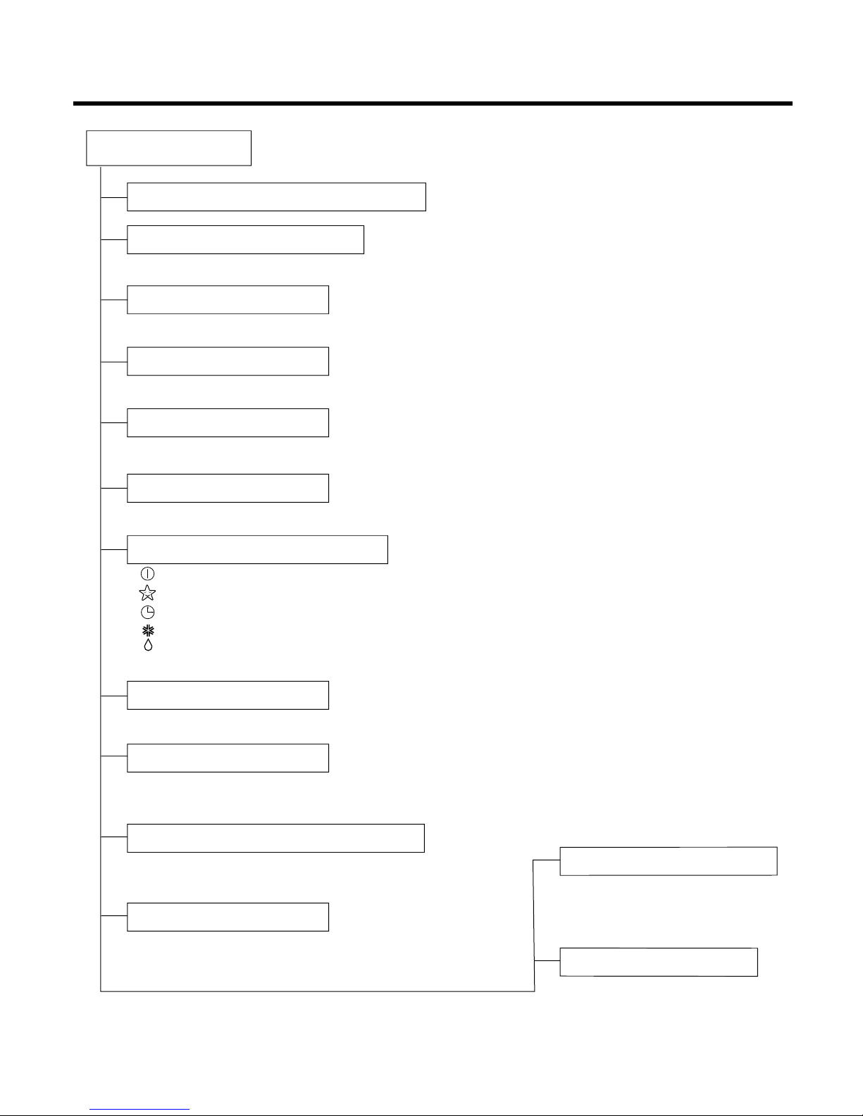
Functions
Indoor Unit
Operation ON/OFF by Remote controller
Sensing the Room Temperature
Room temperature control
Starting Current Control
Time Delay Safety Control
Indoor Fan Speed Control
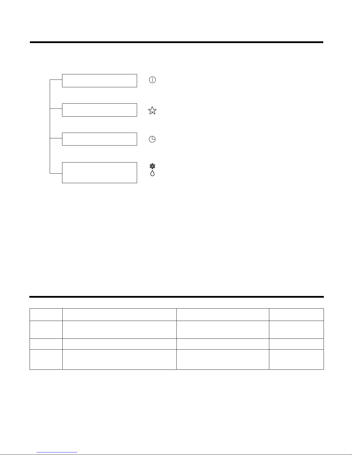
Operation indication Lamps (LED)
Healthy Dehumidification Mode
Sleep Mode Auto Control
Auto Air Control by the unit electronic control
Chaos Swing
Defrost control(Heating)
Hot-start Control (Heating)
• Room temperature sensor (THERMISTOR)
• Maintains the room temperature in accordance with the Setting Temp.
• Indoor fan is delayed for 5 seconds at the starting.
• Restarting is inhibited for approx. 3 minutes.
• High, Med, Low and Auto
• Intermittent operation of fan at low speed
• Both the indoor and outdoor fan stops
during defrosting.
• Hot start will be operated after
defrosting ends.
• The indoor fan stops until the
indoor pipe temperature will be
reached at 28°C(82°F).
• The fan is switched to low(Cooling), med(Heating) speed.
• The unit will be stopped after 1, 2, 3, 4, 5, 6, 7 hours.
• The fan is switched to intermittent or irregular operation.
• The fan speed is automatically switched from high to low speed.
• The louver can be set at the desired position or swing up
and down automatically.
--- Lights up in operation
--- Lights up in Sleep Mode
--- Lights up in Timer Mode
--- Lights up in Defrost Mode or Hot Start Mode (only Heating Model)
--- Lights up during compressor running (only Cooling Model)
OUT
DOOR
Page 4
- 4 -
Healthy Dehumidification Operation Mode.
( )
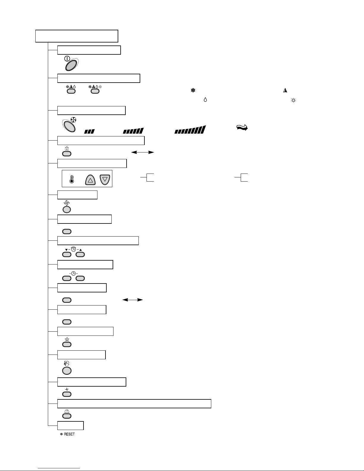
Remote Controller
Operation ON/OFF
Reset
Operation Mode Selection
Temperature Setting
Timer Selection
Timer Setting
JET COOL
Timer Cancel
Sleep Operation
Chaos Swing
(Cooling
model only)
(Heating
model only)
TEMPERATURE
LOW HIGH
Cooling Operation Mode.( )
Heating Operation Mode.( )
Auto Operation Mode.( )
Fan Operation Mode
Horizontal Airflow Direction Control Button(Option)
Room, Temperature Display
Setting the Time or Timer
Selecting °C / °F
ON OFF
SET
°C / °F
CANCEL
Fan Speed Selection
(Low) (Med) (High) (CHAOS)
: (High: 39°C(98°F) LOW : 12°C(54°F)
Down to 18°C(64°F)
Up to 30°C(86°F)
Cooling
: OFF, ON, OFF ON
: Cancel Sleep Mode, Timer ON or Timer OFF
: 1, 2, 3, 4, 5, 6, 7, Off Timer
: Fan Operates without cooling or heating.
Down to 16°C(60°F)
Up to 30°C(86°F)
Heating
Page 5
- 5 -
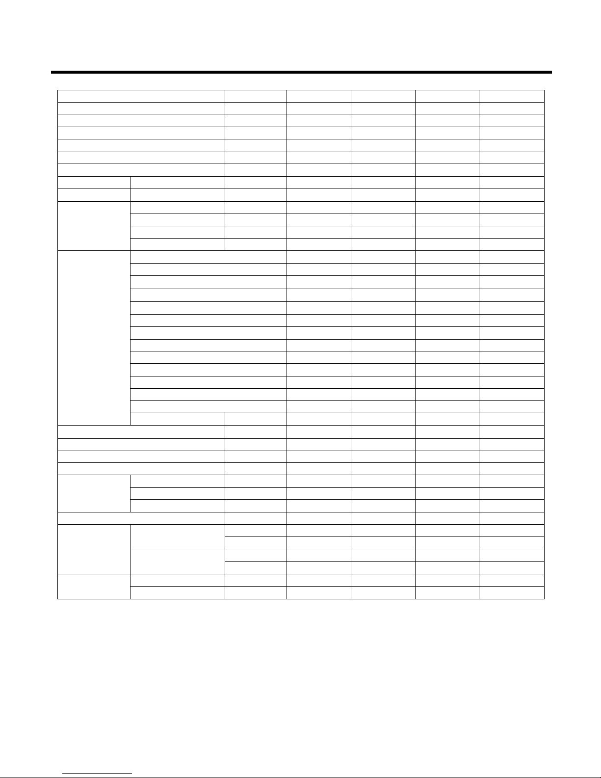
Product Specifications(Cooling Only)
Items Unit HMC009KD1 HMC012KD1 HMC018KD1 HMC024KD1
Power Supply ø, V, Hz
Cooling Capacity BTU/h
Input W
Running Current A
COMP. Locked Rotor AMP. A
E.E.R BTU/hW
Air Circulation m3/min(cfm)
Moisture Removal l/h(pts/hr)
Noise Level Indoor, High dB(A)
(Sound Med dB(A)
Pressure, 1m) Low dB(A)
Outdoor, Max dB(A)
Features Temperature Control
Air Deflection
Steps, Fan/Cool
Airflow Direction Control(up&down)
Airflow Direction Control(left&right)
Remocon Type
Setting Temperature Range, Cooling Mode
Temperature Increment
Auto Operation(electronic control)
Self Diagnosis
Timer
Sleep Operation
Healthy Dehumidification Mode
Restart Delay minutes
Refrigerant(R-22) Charge g(oz)
Power cord AWG #: P*mm
2
Fuse or breaker Capacity A
Connecting Cable AWG #: P*mm
2
Connecting Tube Liquid Side mm(in)
(ø. Socket Flare) Gas Side mm(in)
Length, std m(ft)
Additional Drain Hose(Outer Dia.) mm(in)
Dimensions Indoor mm
(WxHxD) in
Outdoor mm
in
Net Weight Indoor kg(lbs)
Outdoor kg(lbs)
1, 115, 60 1, 115, 60 1, 230/208, 60 1, 230/208, 60
9,000 12,000 18,000/17,800 23,000/22,600
900 1,290 1,900/1,870 2,550/2,500
8.5 11.7 8.5/9.0 11.5/12.0
4.6 47 67
9 9.3 9.5/9.5 9.0/9.0
9.4(330) 9.4(330) 13(460) 15(530)
1.4(3) 1.4(3) 2.5(5.3) 3.1(6.6)
41 41 44 49
39 39 41 45
37 37 38 40
48 48 55 57
Thermistor Thermistor Thermistor Thermistor
4-way 4-way 4-way 4-way
3/3 3/3 3/3 3/3
Auto Auto Auto Auto
Manual Manual Manual Manual
Wireless LCD Wireless LCD Wireless LCD Wireless LCD
64~86°F 64~86°F 64~86°F 64~86°F
2°F2°F2°F2°F
Yes Yes Yes Yes
Yes Yes Yes Yes
24hr, On/Off 24hr, On/Off 24hr, On/Off 24hr, On/Off
Yes Yes Yes Yes
Yes Yes Yes Yes
333 3
630(22.2) 1,250(44.1) 1,250(44.1) 2,000(70.5)
14:3*2.5 14:3*2.5 14:3*2.5 12:3*2.5
15A 20A 20A 25A
18:4*0.75 18:4*0.75 18:4*0.75 18:4*0.75
6.35(1/4) 6.35(1/4) 6.35(1/4) 9.52(3/8)
12.7(1/2) 12.7(1/2) 15.88(5/8) 15.88(5/8)
7.62(25) 7.62(25) 7.62(25) 7.62(25)
15.5(5/8) 15.5(5/8) 15.5(5/8) 15.5(5/8)
888*287*170 888*287*170 1,080*314*181 1,080*314*181
35.0*11.3*6.7 35.0*11.3*6.7 42.5*12.4*7.1 42.5*12.4*7.1
770*540*245 770*540*245 870*655*320 870*655*320
30.3*21.3*9.6 30.3*21.3*9.6 34.3*25.8*12.6 34.3*25.8*12.6
9.5(20.9) 9.5(20.9) 13(28.7) 13(28.7)
32(70.5) 32(70.5) 61(134.5) 62(136.7)
* Design and Specifications subject to change without prior notice for product improvement.
Page 6
- 6 -
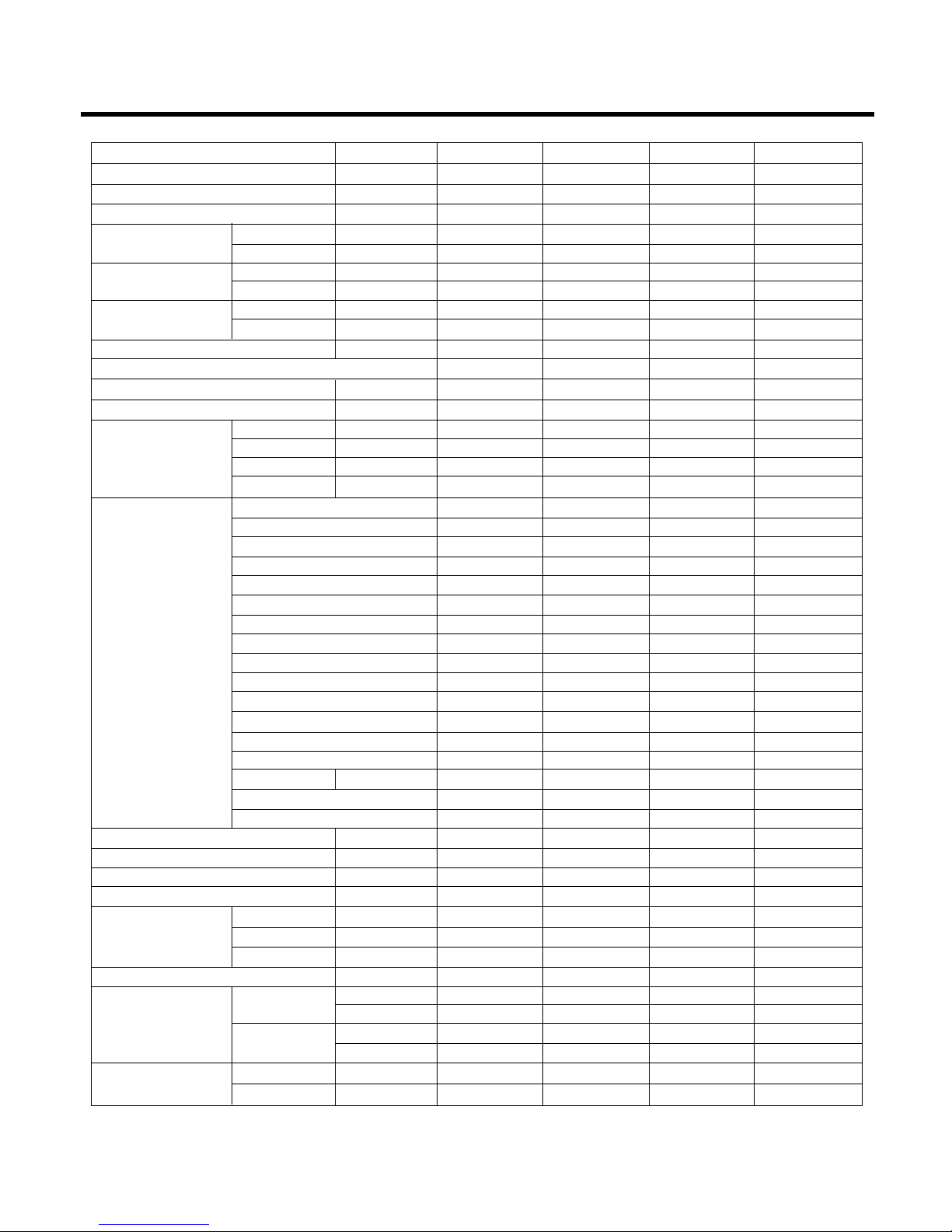
Product Specifications(Cooling & Heating)
Items Unit HMH009KD1 HMH012KD1 HMH018KD1 HMH024KD1
Power Supply ø, V, Hz 1, 115, 60 1, 115, 60 1, 230/208, 60 1, 230/208, 60
Cooling Capacity BTU/h 9,000 12,000 18,000/17,800 23,000/22,600
Heating Capacity BTU/h 9,000 12,000 19,000/18,700 23,000/22,600
Input Cooling W 900 1,290 1,900/1,870 2,550/2,500
Heating W 900 1,290 1,900/1,870 2,550/2,500
Running Current Cooling A 8 11.7 8.5/9.0 11.5/12.0
Heating A 8 11.7 8.5/9.0 11.5/12.0
COMP. Locked Cooling A 51 58 42 67
Rotor AMP. Heating A 51 58 42 67
E.E.R BTU/hW 9 9.3 9.5/9.5 9.0/9.0
C.O.P 2.93 2.75 2.9/2.9 2.6/2.6
Air Circulation m3/min(cfm) 7.1(250) 9.4(330) 13(460) 15(530)
Moisture Removal l/h(pts/hr) 1.2(2.6) 1.4(3) 2.5(5) 3.1(6.6)
Noise Level Indoor, High dB(A) 38 41 44 47
(Sound Med dB(A) 36 39 41 44
Pressure, 1m) Low dB(A) 35 37 38 40
Outdoor, Max dB(A) 48 48 55 58
Features Temperature Control Thermistor Thermistor Thermistor Thermistor
Air Deflection 4-way 4-way 4-way 4-way
Steps, Fan/Cool/Heat 3/3/3 3/3/3 3/3/3 3/3/3
Airflow Direction Control(up&down) Auto Auto Auto Auto
Airflow Direction Control(left&right) Manual Manual Manual Manual
Remocon Type Wireless LCD Wireless LCD Wireless LCD Wireless LCD
Setting Temperature Range, Cooling Mode
64~86°F 64~86°F 64~86°F 64~86°F
Heating Mode 60~86°F 60~86°F 60~86°F 60~86°F
Temperature Increment 2°F2°F2°F2°F
Auto Operation(electronic control) Yes Yes Yes Yes
Self Diagnosis Yes Yes Yes Yes
Timer 24hr, On/Off 24hr, On/Off 24hr, On/Off 24hr, On/Off
Sleep Operation Yes Yes Yes Yes
Healthy Dehumidification Mode Yes Yes Yes Yes
Restart Delay minutes 3 3 3 3
Defrost Control Yes Yes Yes Yes
Hot Start Yes Yes Yes Yes
Refrigerant(R-22) Charge g(oz) 700(24.7) 840(29.6) 1350(47.6) 1900(67.0)
Power cord AWG #: P*mm
2
14:3*2.5 14:3*2.5 14:3*2.5 14:3*2.5
Fuse or breaker Capacity A 20A 20A 20A 25A
Connecting Cable AWG #: P*mm218:4*0.75 18:4*0.75 18:4*0.75 18:4*0.75
Connecting Tube Liquid Side mm(in) 6.35(1/4) 6.35(1/4) 6.35(1/4) 9.52(3/8)
(ø. Socket Flare) Gas Side mm(in) 12.7(1/2) 12.7(1/2) 15.88(5/8) 15.88(5/8)
Length, std m(ft) 7.62(25) 7.62(25) 7.62(25) 7.62(25)
Additional Drain Hose(Outer Dia.) mm(in) 15.5(5/8) 15.5(5/8) 15.5(5/8) 15.5(5/8)
Dimensions Indoor mm 802*262*165 888*287*170 1080*314*181 108*314*181
(WxHxD) in 31.6*10.3*6.5 35.0*11.3*6.7 42.5*12.4*7.1 42.5*12.4*7.1
Outdoor mm 770*540*245 770*540*245 870*655*320 870*655*320
in 30.3*21.3*9.6 30.3*21.3*9.6 34.3*25.8*12.6 34.3*25.8*12.6
Net Weight Indoor kg(lbs) 7(15.4) 9.5(20.9) 13(28.7) 13(28.7)
Outdoor kg(lbs) 33(72.8) 33(72.8) 62(136.7) 63(138.9)
* Design and Specifications subject to change without prior notice for product improvement.
Page 7
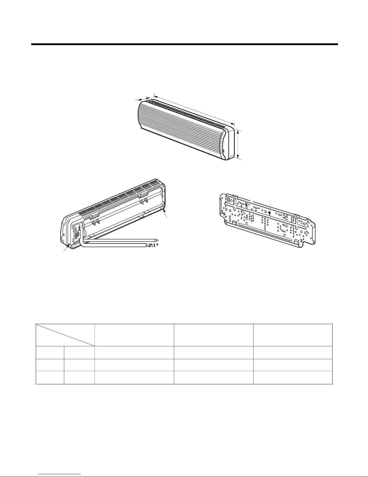
(1) Indoor Unit
- 7 -
Dimensions
D
W
H
Tubing hole cover
Tubing hole cover
Installation plate
MODEL
9K 12K 18K, 24K
DIM
W mm(inch) 802(31.6") 888(35.0") 1,080(42.5")
H mm(inch) 262(10.3") 287(11.3") 314(12.4")
D mm(inch) 165(6.5") 170(6.7") 181(7.1")
Page 8
- 8 -
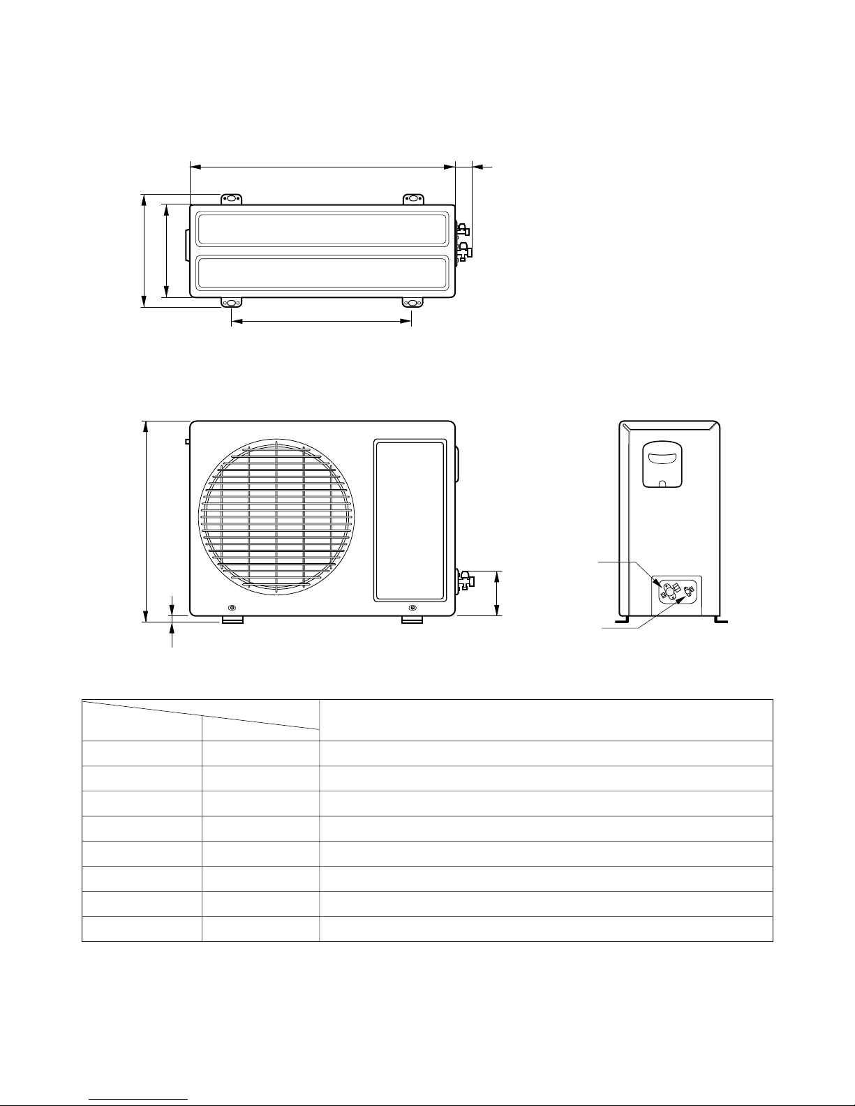
(2) Outdoor Unit
1. 9K, 12K
W
L2
L3
L1
D
H
L4
L5
Gas side
(3-way valve)
Liquid side
(2-way valve)
MODEL
9K, 12K
DIM unit
W mm(inch) 770(30.3)
H mm(inch) 540(21.3)
D mm(inch) 245(9.6)
L1 mm(inch) 287(11.3)
L2 mm(inch) 64(2.5)
L3 mm(inch) 518(20.4)
L4 mm(inch) 10(0.4)
L5 mm(inch) 100(3.9)
Page 9
- 9 -
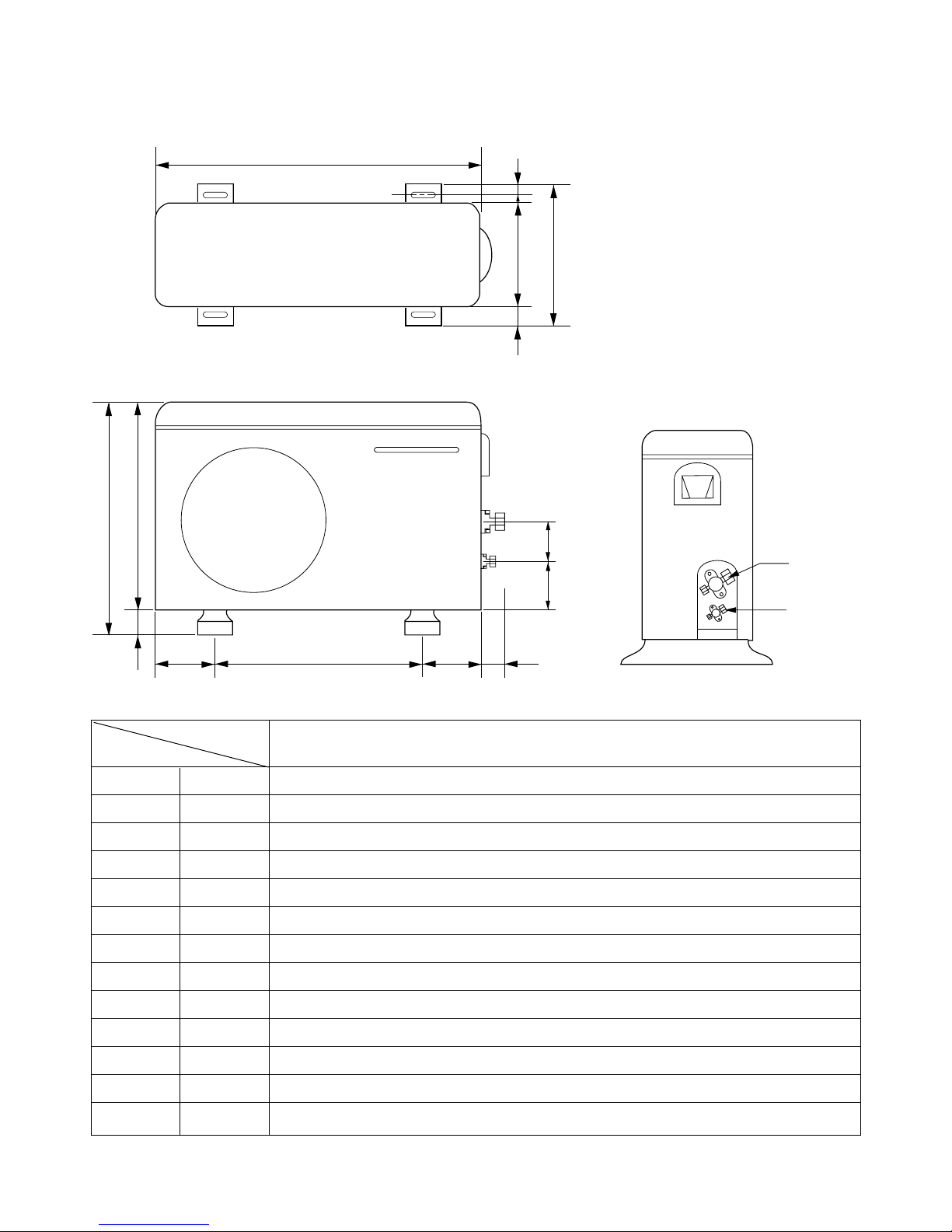
W
L6 L5 L7 L8
D
L1
L2
L9L10
L3L4
H
Gas side
3-way valve
Liquid side
3-way valve
2. 18K, 24K
MODEL
18K, 24K
DIM
W mm(inch) 870(34.3)
H mm(inch) 655(25.8)
D mm(inch) 320(12.6)
L1 mm(inch) 370(14.6)
L2 mm(inch) 25(1.0)
L3 mm(inch) 630(24.8)
L4 mm(inch) 25(1.0)
L5 mm(inch) 546(21.5)
L6 mm(inch) 162(6.4)
L7 mm(inch) 162(6.4)
L8 mm(inch) 54(2.1)
L9 mm(inch) 74.5(2.9)
L10 mm(inch) 79(3.1)
Page 10
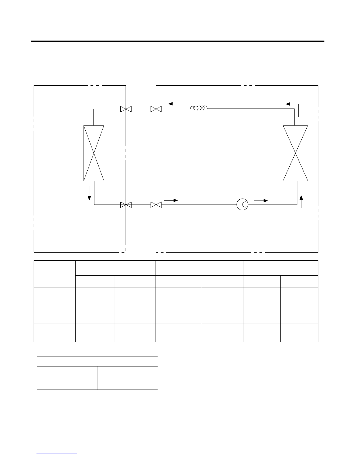
- 10 -
For installation over rated, *a proper quantity of refrigerant
should be added for each meter.
Ex) 18K: When installed at a distance of 15m, 295g of
refrigerant should be added.
(15-7.62) x 40g = 295g
INDOOR UNIT
HEAT
EXCHANGER
(EVAPORATOR)
HEAT
EXCHANGER
(CONDENSER)
COMPRESSOR
GAS SIDE
CAPILLARY TUBE
LIQUID SIDE
OUTDOOR UNIT
• Cooling Only Models
MODEL
9K, 12K
(Cooling Only)
18K
(Cooling Only)
24K
(Cooling Only)
Pipe size(Diameter:ø) Piping length Elevation
Gas Liquid Rated Max Rated Max
1/2" 1/4" 7.62m(25ft) 15m(50ft) 5m(16ft) 8m(26ft)
5/8" 1/4" 7.62m(25ft) 15m(50ft) 5m(16ft) 8m(26ft)
5/8" 3/8" 7.62m(25ft) 15m(50ft) 5m(16ft) 8m(26ft)
Refrigeration Cycle Diagram
a proper quantity of refrigerant
9K, 12K 20g
18K, 24K 40g
Page 11
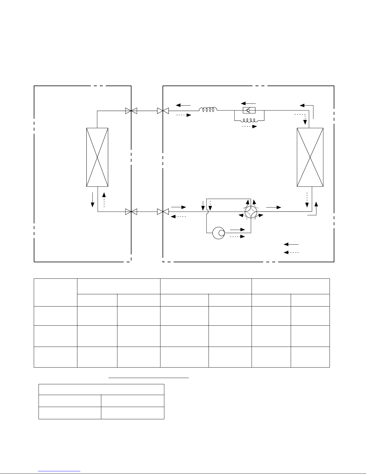
- 11 -
INDOOR UNIT
HEAT
EXCHANGER
(EVAPORATOR)
HEAT
EXCHANGER
(CONDENSER)
REVERSING
VALVE
COMPRESSOR
COOLING
HEATING
GAS SIDE
CAPILLARY TUBE
CHECK VALVE
LIQUID SIDE
OUTDOOR UNIT
• Cooling & Heating Models
MODEL
9K, 12K
(Cooling & Heating)
18K
(Cooling & Heating)
24K
(Cooling & Heating)
Pipe size(Diameter:ø) Piping length Elevation
Gas Liquid Rated Max Rated Max
1/2" 1/4" 7.62m(25ft) 15m(50ft) 5m(16ft) 8m(26ft)
5/8" 1/4" 7.62m(25ft) 15m(50ft) 5m(16ft) 8m(26ft)
5/8" 3/8" 7.62m(25ft) 15m(50ft) 5m(16ft) 8m(26ft)
For installation over rated, *a proper quantity of refrigerant should be added for each meter.
Ex) 18K: When installed at a distance of 15m, 295g of
refrigerant should be added.
(15-7.62) x 40g = 295g
a proper quantity of refrigerant
9K, 12K 20g
18K, 24K 40g
Page 12
- 12 -
Wiring Diagram
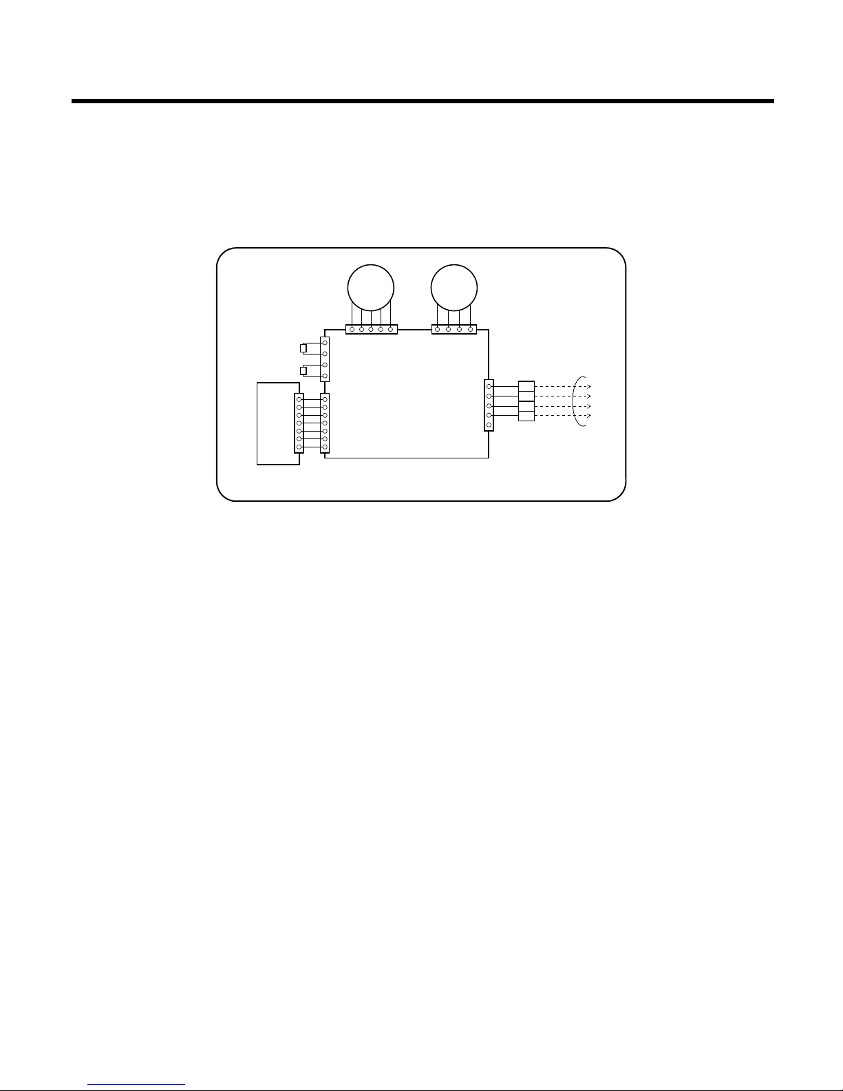
(1) Indoor Unit
1. 9K, 12K, 18K, 24K(Cooling Only Models, Cooling & Heating Models)
4
3
2
1
BLDC
MOTOR
STEP
MOTOR
MAIN P.C.B
INDOOR WIRING DIAGRAM
TO OUTDOOR UNIT
DISPLAY P.C.B
(R
O
O
M
)
(PIPE)
TH
E
R
M
ISTO
R
C
N
-U
P
/D
O
W
N
3854AR7074A
C
N
-M
O
TO
R
PILLAR
TER
M
IN
AL
C
N
-D
C
/D
C
C
N
-D
ISP
C
N
-TH
BL
BK
BR
RD
Page 13

- 13 -
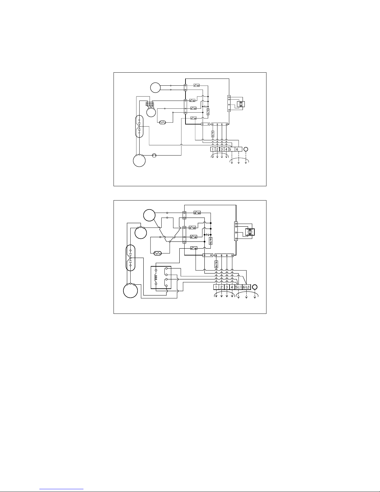
(2) Outdoor Unit
• Cooling Only Models
1. 9K, 12K
3. 24K
2. 18K
BL
BL
BK
BK
FUSE
3.15A
FUSE
2.5A
ZNR
CN-DC/DC
RY-COMP
34
MAIN P.C.B
YL
MOTOR
RD
BL
BR
BL
RD
BR
BL
TERMINAL
BLOCK
TO INDOOR UNIT
POWER
INPUT
3854A30077ZOUTDOOR WIRING DIAGRAM
RD
BR BK BL
G
H
F
C
CAPACITOR
CN-TRANS
TRANSFORMER
T/B 1
CN-POWER
BR
BR YL
O.L.P
COMP.
S
RC
(N)(L)
BL
BL
BK
BK
FUSE
3.15A
FUSE
2.5A
ZNR
CN-DC/DC
RY-COMP
34
MAIN P.C.B
BK
T/B 1
MOTOR
YL
OR(BR)
BR
BR
BR
BR
RD
BL
BL
1
8
6
4
2
0
BL
TERMINAL
BLOCK
TO INDOOR UNIT
POWER
INPUT
3854AR7077JOUTDOOR WIRING DIAGRAM
RD BR BK BL
G
H
F
C
CAPACITOR
COMP.
R
C
YLBR
BR
O.L.P
BL
S
CN-TRANS
TRANSFORMER
CN-POWER
BL
BL
BK
BK
FUSE
3.15A
FUSE
2.5A
ZNR
CN-DC/DC
RY-COMP
34
MAIN P.C.B
BK
T/B 1
MOTOR
YL
OR(BR)
BR
BR
BR
BR
RD
BL
BL
1
8
6
4
2
0
BL
TERMINAL
BLOCK
TO INDOOR UNIT
POWER
INPUT
3854AR7077LOUTDOOR WIRING DIAGRAM
RD BR BK BL
G
H
F
C
CAPACITOR
COMP.
R
C
YLBR
BL
S
CN-TRANS
TRANSFORMER
CN-POWER
Page 14
- 14 -
• Cooling & Heating Models
1. 9K, 12K
2. 18K, 24K
4WAY-
VALVE
BK
RD
RY-4WAY
BL
BL
BK
BK
FUSE
3.15A
RY-FAN
RY-HEATER
ZNR
CN-DC/DC
RY-COMP
34
MAIN P.C.B
BK
YL
MOTOR
RD
BL
RD
BR
BL
RDBR
O.L.P
BL
TERMINAL
BLOCK
TO INDOOR UNIT
POWER
INPUT
3854A30077WOUTDOOR WIRING DIAGRAM
RD BR BK BL
WHWH
G
WH
WH
H
F
C
CAPACITOR
COMP.
R
C
YLBR
S
CRANK
CASE
HEATER
CN
-
4WAY
CN-TRANS
TRANSFORMER
CN
-
FAN
T/B 3
T/B 1
T/B 2
T/B 4
CN-POWER
FUSE
2.5A
(N)(L)
4WAYVALVE
BK
RD
RY-4WAY
BL
BL
BK
BK
FUSE
3.15A
FUSE
2.5A
RY-FAN
RY-HEATER
ZNR
CN-DC/DC
RY-COMP
34
MAIN P.C.B
BK
BK
MOTOR
YL
OR(BR)
RD
BK
BR
BR
BR
BL
RD
BL
BL
1
8
6
4
2
0
BL
TERMINAL
BLOCK
TO INDOOR UNIT
POWER
INPUT
3854AR7077MOUTDOOR WIRING DIAGRAM
RD BR BK BL
WHWH
G
WH
WH
H
F
C
CAPACITOR
COMP.
R
C
YLBR
S
CRANK CASE
HEATER
CN
-
4WAY
CN-TRANS
TRANSFORMER
CN
-
FAN
T/B 1
T/B 3
T/B 4
T/B 2
CN-POWER
Page 15
(1) The function of main control
1. Time delay Safety Control
• 3min.; The compressor operation is delayed for 3 minutes to balance the pressure of cycle.
(Protection of compressor)
• 5sec.;
The indoor fan is delayed for 5 seconds, when operating initially, to prevent noises occurred by the vertical
louver and wind.
• 2min.; The reversing valve is delayed for 2 minutes to prevent the refrigerant-gas for abnormal noise when the
heating operation is OFF or switched to the other operation mode while compressor is off.
While compressor is running, it takes 3~5 seconds to switch.
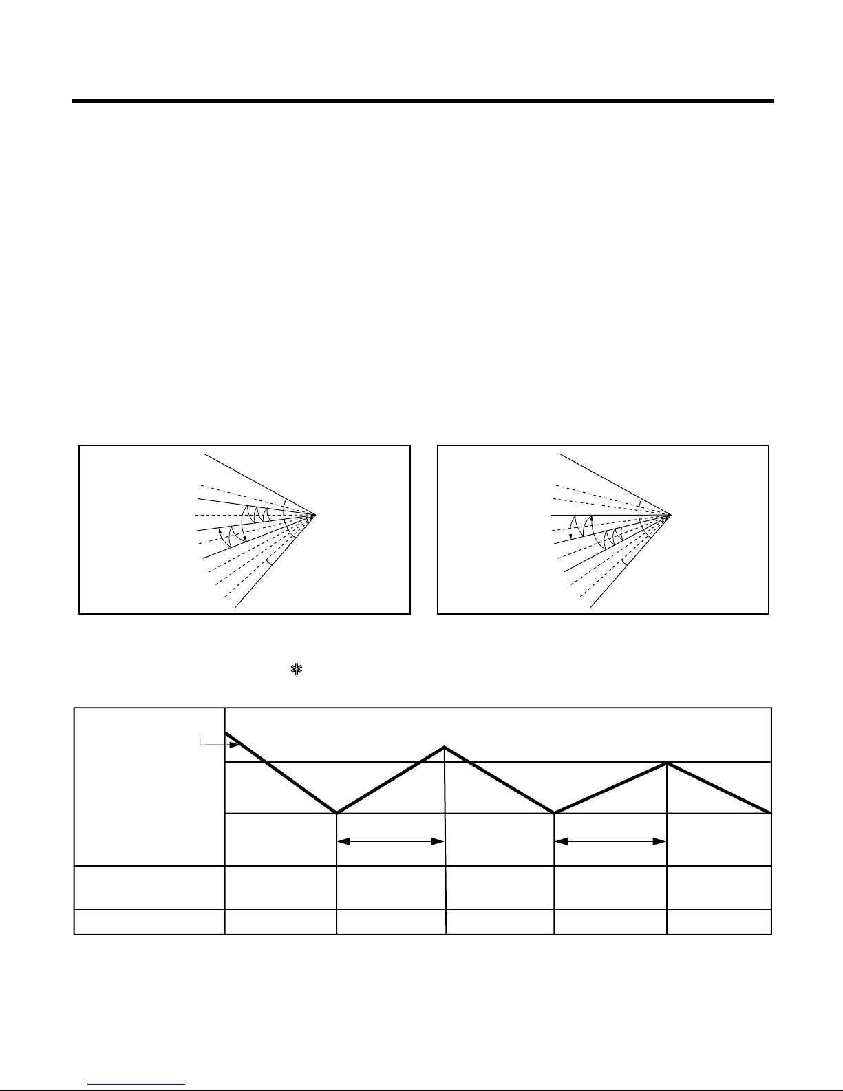
2. Chaos Swing Mode
• By the Chaos Swing key input, the upper/lower vane automatically operates with the Chaos Swing or they are
fixed to the desired direction.
• While in Chaos Swing mode, the angles of cooling and heating cycle operations are different.
- 15 -
Operation Details
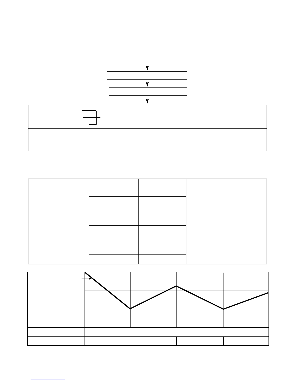
INTAKE AIR TEMP.
SETTING TEMP. +1°F
(Compressor ON)
SETTING TEMP. -1°F
(Compressor OFF)
Setting
fan speed
Setting
fan speed
More than
3 minutes
More than
3 minutes
Setting
fan speed
COMPRESSOR ON OFF ON OFF ON
INDOOR FAN SPEED Low Low
■ Protection of the indoor heat exchanger from frosting
• Compressor and outdoor fan stop when indoor pipe temperature is below 0°C(32°F) and restart at the pipe
temperature is above 7°C(45°F).
3. Cooling Operation Mode
• When selecting the Cooling( ) Mode Operation, the unit will operate according to the setting by the
remote control and the operation diagram is shown below.
CLOSED
OPEN
< Cooling Mode >
8°
CLOSED
OPEN
< Heating Mode >
8°
Page 16
4. Auto Operation (Electronic control mode)
• The operation procedure is shown below. (Cooling & Heating Model)
❋ If initial mode is decided, that mode is continued without the room temperature changing.
■ Auto Operation for Cooling
- 16 -
Press Start/Stop Button
Select Auto Operation Mode
Check the Room temperature
Operation mode
Indoor fan speed are decided automatically by the unit electronic control.
Setting temperature
Intake-air
temperature
Operation Mode
Over below
70°F76
°
F
Soft Dry
below 70°F
Heating
Over 76°F
Cooling
~
INTAKE AIR TEMP.
SETTING TEMP. +1°F
(Compressor OFF)
SETTING TEMP. -1°F
(Compressor ON)
COMPRESSOR ON OFF ON OFF
INDOOR FAN SPEED The electronic control operation
Intake-air Temperature Setting Temperature
Over 78°F77°F
Over 76°F~below 78°F Intake air -1°C
Over 72°F~below 76°F Intake air -0.5°C
Over 68°F~below 72°F Intake air temperature
below 64°F64°F
Over 64°F~below 86°F Electronic control
below 64°F64°F
over 86°F86°F
Operation Condition
When Auto Operation
initial start
Controlled by
the electronic
control
In this mode,
when pressing
the vertical air
direction control
button, vertical
louver swings up
and down
automatically.
Fan Speed Air Direction Control
When pressing room
temperature setting
button during Auto
Operation
Page 17

■ Auto Operation for Dehumidification(only Heating Model)
• The Setting temperature will be same that of the auto operation for cooling.
- Compressor ON temperature; Setting temperature +2°F
- Compressor OFF temperature; Setting temperture -1°F
■ Auto Operation for Heating(only Heating Model)
- Compressor ON temperature; Setting temperature
- Compressor OFF temperature; Setting temperature +6°F
- 17 -
Intake-air temp. below 68°F Over 68°F~below 70°F over 86°F
Setting temp. 68°F Intake air temperature +1°F86°F
■ Vertical louver auto operation
: During Auto Operation, pressing the chaos swing button makes the horizontal louvers swing up and down automatically.
If you want to stop auto-swing, press chaos swing button again.
Page 18

5. Healthy Dehumidification
• When the dehumidification operation input by the remote control is received, the intake air temperature is
detected and the setting temp is automatically set according to the intake air temperature.
26°C ≤ Intake Air Temp ➲ 25°C
24°C ≤ Intake Intake Air Temp<26°C ➲ Intake Air Temp-1°C
18°C ≤ Intake Intake Air Temp<24°C ➲ Intake Air Temp-0.5°C
Intake Air Temp<18°C ➲ 18°C
• While in compressor off, the indoor fan repeats low airflow speed and pause.
• While the intake air temp is between compressor on temp. and compressor off temp., 10-min dehumidification
operation and 4-min compressor off repeat.
Compressor ON Temp. ➲ Setting Temp+0.5°C
Compressor OFF Temp. ➲ Setting Temp-0.5°C
• In 10-min dehumidification operation, the indoor fan operates with the low airflow speed.
- 18 -
Page 19
- 19 -
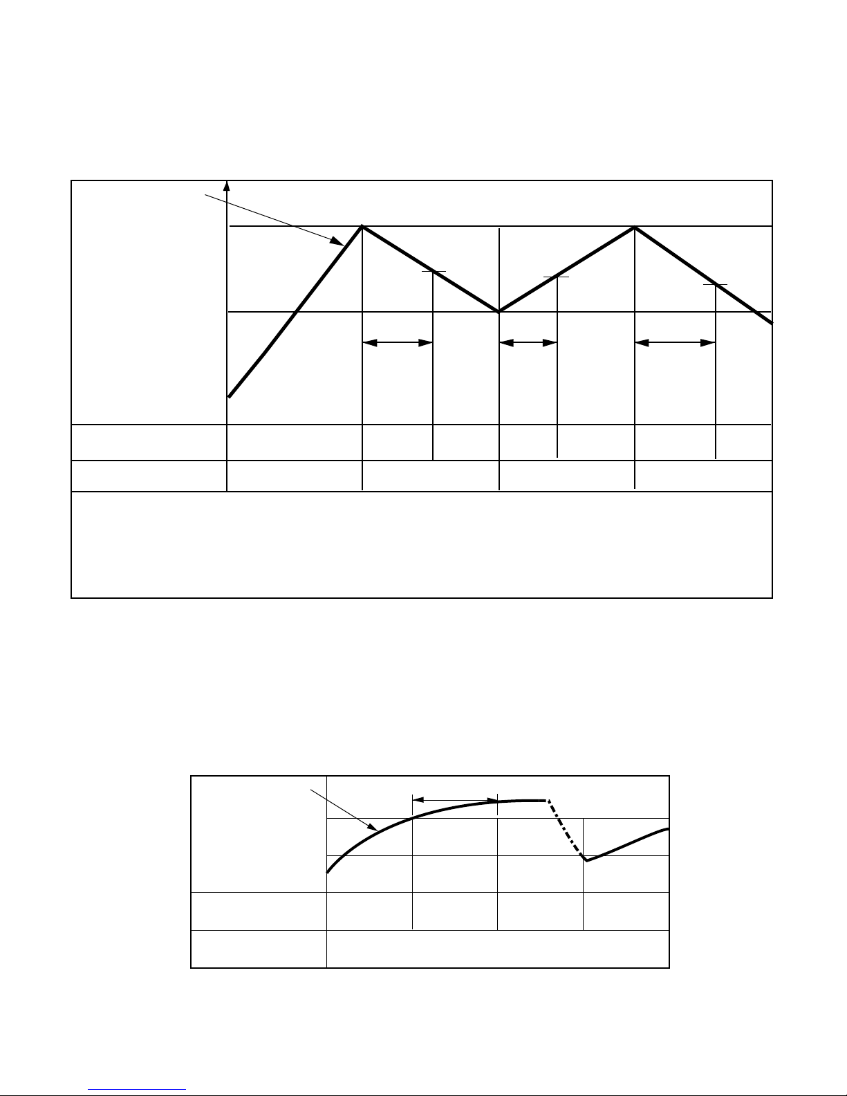
6. Heating Operation Mode(only Heating Model)
The unit will operate according to the setting conditions by the remote controller.
The operation diagram is shown below.
INTAKE AIR TEMP.
SETTING TEMP. +6
°
F
(Compressor OFF)
SETTING TEMP.
(Compressor ON)
Selecting
fan speed
Selecting
fan speed
A
B
A
minimum
10sec.
minimum
1 min.
minimum
10sec.
COMPRESSOR ON OFF ON OFF
• A point; While the indoor pipe temperature is higher than 95°F, indoor fan operates at low speed. When the
indoor pipe temperature becomes lower than 95°F, indoor fan stops.
• B point; When the indoor pipe temperature is higher than 38°C(100°F), fan operates at selected fan speed.
INDOOR FAN SPEED
Low
OFF
Low Low OFF
OFF OFFLOW
ON
Selecting
fan speed
INDOOR PIPE
TEMP.
82°F
78°F
1min
INDOOR FAN SPEED
COMPRESSOR
■ Hot-Start Control
• The indoor fan stops until the indoor pipe temperature will be reached at 82°F.
• During heating operation, if indoor pipe temperature falls below 78°F fan stops.
• The operation diagram is shown below.
Page 20
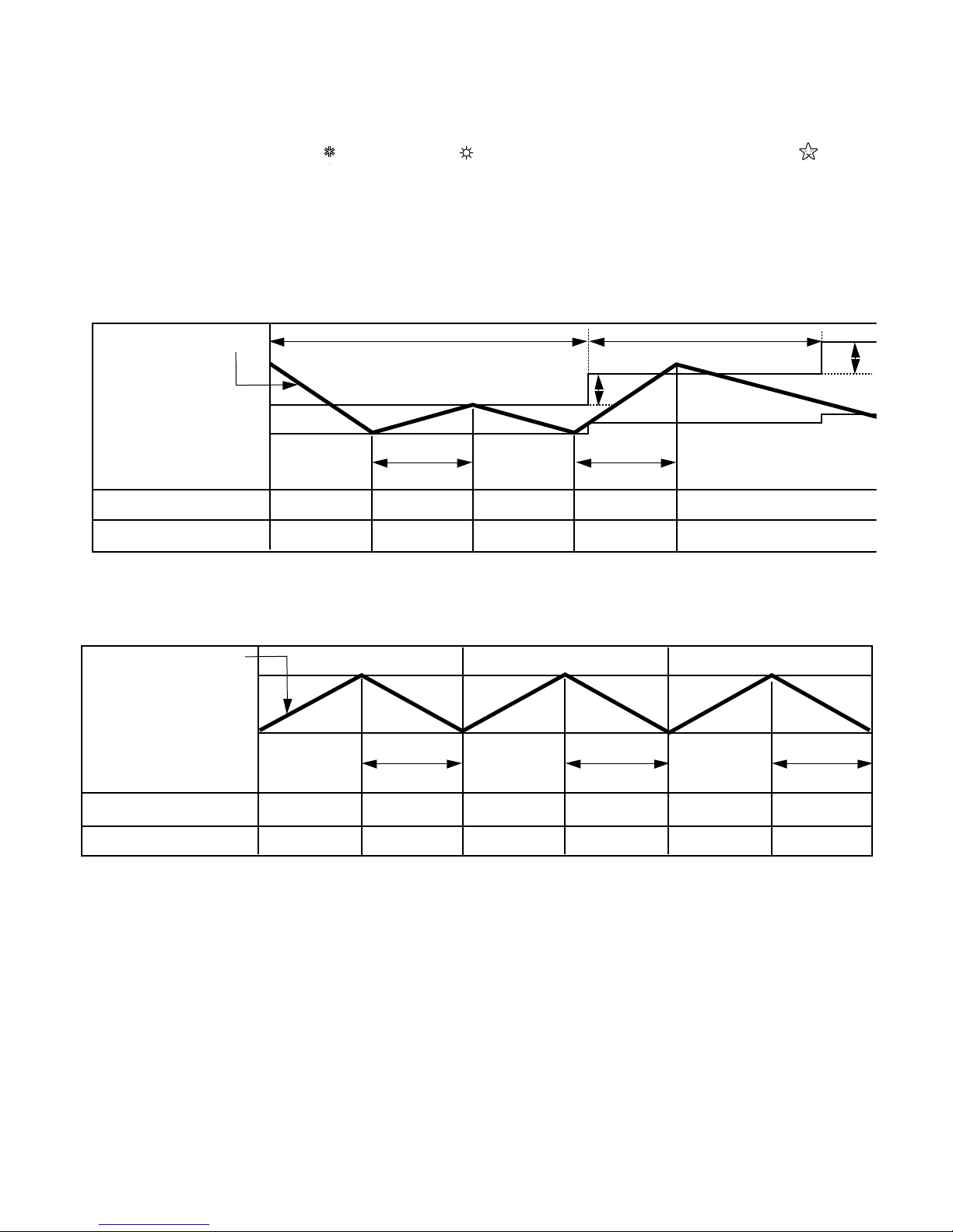
7. Cooling or Heating Mode with Sleep Mode Auto Control
• When selecting the Cooling( ) or the Heating( ) combined with the Sleep Mode Auto Control( ), the
operation diagram is as following.
■ Cooling Mode with the Sleep Mode
• The setting temperature will be automatically raised by 2°F 30 minutes later and by 4
°
F 1 hour later.
• The operation will be stopped after 1, 2, 3, 4, 5, 6, 7 hours.
■ Heating Mode with the Sleep Mode(only Heating Model)
• The operation will be stopped after 1, 2, 3, 4, 5, 6, 7 hours.
- 20 -
INTAKE AIR TEMP.
SETTING TEMP. +1°F
(Compressor ON)
SETTING TEMP. -1°F
(Compressor OFF)
30 minutes
30 minutes
More than
3 minutes
2°F
2°F
More than
3 minutes
COMPRESSOR ON OFF ON OFF ON
INDOOR FAN SPEED Low Low Low Low Low
SETTING TEMP. +6
°
F
(Compressor OFF)
SETTING TEMP.
(Compressor ON)
COMPRESSOR ON OFF ON OFF ON OFF
INDOOR FAN SPEED Med Low or OFF Med Low or OFF Med Low or OFF
INTAKE AIR TEMP.
More than
3 minutes
More than
3 minutes
More than
3 minutes
Page 21
- 21 -
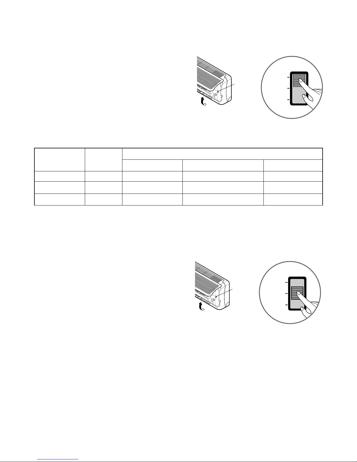
8. Forced Operation
Operation procedures when the remote control can't be
used.
Open the front panel upward and move the Slide Switch
to the Forced Operation position.
If you want to stop operation, move the Slide Switch to
the Auto Restart or the Remote Control position.
In case the power comes on again after power failure on
the Forced Operation position, the operating conditions
are automatically set as follows:
During Forced Operation, the initial mode continues.
9. AUTO RESTART
In case the power comes on again after a power failure,
Auto Restarting Operation is the function to operate procedures automatically to the previous operating conditions.
If you want to use this operation, Open the front panel
upward and move the slide switch to the Auto Restart
position.
If you do not want to use this operation, move the Slide
Switch to the Remote Control position.
When you are out for a while, put the Slide Switch
on the Remote Control.
Cooling Heat pump Model
Model
Room Temp. ≥ 24°C(76°F)
21°C(70°F) ≤ Room Temp. < 24°C(76°F)
Room Temp. < 21°C(70°F)
Operating mode Cooling Cooling Healthy Dehumidification Heating
Indoor FAN Speed
High High
Healthy Dehumidification Rule
High
Setting Temperature
22°C(72°F) 22°C(72°F) 23°C(74°F) 24°C(76°F)
Open the front
panel upward
Slide
Switch
Slide Switch
FORCED
OPERATION
AUTO
RESTART
REMOTE
CONTROL
Open the front
panel upward
Slide
Switch
Slide Switch
FORCED
OPERATION
AUTO
RESTART
REMOTE
CONTROL
Page 22
• Cooling, Soft Dry, Fan, Heating
• Sleep Mode
• Timer Mode
• Hot-start, Defrost
• Compressor ON
• BUZZER SOUND
• Power Input or Reset : One short beep.
• When Operation Stop Button is pressed : One long beep.
• When Remote Controller Buttons except for Operation Stop are pressed : Two short beep.
- 22 -
Display Function
Self-diagnosis Function
Operation Indicator
Sleep timer Indicator
Timer Indicator
Defrost Indicator or
Hot start Indicator
OUT
DOOR
: Cooling & Heating Model only
: only Cooling Model
CODE NO. DIAGNOSIS Operation Indicator LED Blinks Unit Operation
① Once Still Operation
② Outdoor pipe thermistor Short/Open Twice Outdoor Unit Off
③ 5 times Stop
Indoor room temperature thermistor or
pipe temperature thermistor Short/Open
Communication failure between indoor and
outdoor
• LED blinks as many times as code No. (0.5 second ON/0.5 second OFF) with 3 seconds interval.
• While the unit is off, no indication displays.
• If more than one code occurs simultaneously, bigger code No. is displayed.
Page 23

- 23 -
Installation
IMPORTANT!
Please read this instruction sheet completely before installing the product.
This air conditioning system meets strict safety and operating standards. As the installer or service person, it is an important part of
your job to install or service the system so it operates safely and efficiently.
CAUTION:
Improper installation, adjustment, alteration, service or maintenance can void the warranty.
The weight of the condensing unit requires caution and proper handling procedures when lifting or moving to avoid
personal injury. Use care to avoid contact with sharp or pointed edges.
Safety Precautions
• Always wear safety eye wear and work gloves when installing equipment.
• Never assume electrical power is disconnected. Check with meter and equipment.
• Keep hands out of fan areas when power is connected to equipment.
• R-22 causes frostbite burns.
• R-22 is toxic when burned.
NOTE T O INSTALLING DEALER:
The Owners Instructions and Warranty are to be given to the owner or prominently displayed
near the indoor Furnace/Air Handler Unit.
• Installation or repairs made by unqualified persons can result in hazards to you and others.
Installation MUST conform with local building codes or, in the absence of local codes, with the National Electrical Code NFPA 70/ANSI C1-1993 or current edition and Canadian Electrical Code Part1 CSA C.22.1.
• The information contained in the manual is intended for use by a qualified service technician familiar with safety procedures and equipped with the proper tools
and test instruments.
• Failure to carefully read and follow all instructions in this manual can result in equipment malfunction, property damage, personal injury and/or death.
WARNING
Special warnings
When wiring:
Electrical shock can cause severe personal injury or death. Only a qualified, experienced electrician should attempt to wire this system.
• Do not supply power to the unit until all wiring and tubing are completed or reconnected and checked.
• Highly dangerous electrical voltages are used in this system. Carefully refer to the wiring diagram and these instructions when wiring. Improper connections
and inadequate grounding can cause accidental injury or death.
• Ground the unit following local electrical codes.
• Connect all wiring tightly. Loose wiring may cause overheating at connection points and a possible fire hazard.
When transporting:
Be careful when picking up and moving the indoor and outdoor units. Get a partner to help, and bend your knees when lifting to reduce strain on
your back. Sharp edges or thin aluminum fins on the air conditioner can cut your finger.
When installing...
... in a wall: Make sure the wall is strong enough to hold the unit's weight.
It may be necessary to construct a strong wood or metal frame to provide added support.
... in a room: Properly insulate any tubing run inside a room to prevent "sweating" that can cause dripping and water damage to wall and floors.
... in moist or uneven locatinons: Use a raised concrete pad or concrete blocks provide a solid, level foundation for the outdoor unit. This prevents
water damage and abnormal vibration.
... in an area with high winds:
Securely anchor the outdoor unit down with bolts and a metal frame. Provide a suitable air baffle.
... in a snowy area(for Heat Pump Model): Install the outdoor unit on a raised platform that is higher than drifting snow. Provide snow vents.
When connecting refrigerant tubing
• Keep all tubing runs as short as possible.
• Use the flare method for connecting tubing.
• Check carefully for leaks before starting the test run.
When servicing
•
Turn the power OFF at the main power box(mains) before opening the unit to check or repair electrical parts and wiring.
• Keep your fingers and clothing away from any moving parts.
Page 24

(1) Installation Parts Provided
(2) Installation of indoor, outdoor unit
Read completely, then follow step by step.
1) Select the best location
1. Indoor unit
■ Do not have any heat or steam near the unit.
■ Select a place where there are no obstacles in front of the
unit.
■ Make sure that condensation drainage can be conveniently routed away.
■ Do not install near a doorway.
■ Ensure that the space around the left and right of the unit
is more than 5cm(2"). The unit should be installed as high
on the wall as possible, allowing a minimum of 5cm(2")
from ceiling.
■ Use a stud finder to locate studs to prevent unnecessary
damage to the wall.
2. Outdoor unit
■ If an awning is built over the unit to prevent direct sunlight
or rain exposure, make sure that heat radiation from the
condenser is not restricted.
■ Ensure that the space around the back and sides is more
than 10cm. The front of the unit should have more than
70cm of space.
■ Do not place animals and plants in the path of the warm
air.
■ Take the air conditioner weight into account and select a
place where noise and vibration are minimum.
■ Select a place so that the warm air and noise from the air
conditioner do not disturb neighbors.
■
Rooftop Installations:
If the outdoor unit is installed on a roof structure, be sure to
level the unit. Ensure the roof structure and anchoring
method are adequate for the unit location. Consult local
codes regarding rooftop mounting.
2) Piping length and elevation
- 24 -
1. Type "A" screw
2. Installation Plate
3. Type "B" screw
4. Holder Remote Control
More than 5cm(2")
More than
5cm(2")
More than 2.3m(7.5ft)
More than
5cm(2")
More than
10cm(4")
More than 10cm(4")
More
than 60cm(24")
More than 60cm(24")
More than
70cm(28")
Install the indoor unit on the wall where the height from the
floors more than 2.3 meters(7.5ft).
CAUTION
MODEL
(Cooling Capa.)
Pipe Size
GAS
LIQUID
Max
length
A
Max
Elevation
B
9K, 12K 1/2" 1/4" 15m(50ft) 8m(26ft)
18K 5/8" 1/4" 15m(50ft) 8m(26ft)
24K 5/8" 3/8" 15m(50ft) 8m(26ft)
A
Outdoor unit
Indoor unit
B
A
Oil trap
Outdoor unit
Indoor unit
B
In case more than 5m(16.4ft)
• Capacity is based on standard length and maximum
allowance length is on the basis of reliability.
• Oil trap should be installed every 5~7 meters(16.4~23ft).
CAUTION
Page 25

3) How to fix installation plate
The wall you select should be strong and solid enough to
prevent vibration
1. Mount the installation plate on the wall with four
type A screws. If mounting the unit on a concrete
wall, use anchor bolts.
■ Mount the installation plate horizontally by aligning the
centerline using a level.
2. Measure the wall and mark the centerline. It is also
important to use caution concerning the location of
the installation plate-routing of the wiring to power
outlets is through the walls typically. Drilling the
hole through the wall for piping connections must
be done safely.
■ For right rear piping and left rear piping, draw a line in the
direction of the arrow marked "A". The meeting point of the
two lines is the center of the hole.
• The position of the center of the hole.
4) Drill a hole in the wall
■ Drill the piping hole with a ø70mm (0.76") hole core drill.
Drill the piping hole at either the right or the left with the
hole slightly slanted to the outdoor side.
- 25 -
Hole center
Right rear piping
Left rear piping
ø70mm
(2.76")
ø70mm
(2.76")
50mm
(1.97")
20mm
(0.79")
20mm
(0.79")
80mm(3.15")
A,B
A,B,C
C
D
D
A,B,D
C
A
B,D
C
ø70mm(2.76")
Left rear piping Right rear piping
Hole Center Installation plate
9K Btu
12K Btu
A,B
A,B,C
C
D
D
A,B,D
C
A
B,D
C
ø70mm(2.76")
Left rear piping Right rear piping
Hole Center Installation plate
18, 24K Btu
5-7mm
(0.2~0.3")
Indoor
WALL
Outdoor
Installation Plate
Marking-off line
Thread
Weight
Type "A" screw
A
A
A
A
Left holecore position Right holecore position
Page 26

(3) Flaring work and connection
of piping
1) Flaring work
Main cause for gas leakage is due to defect in flaring
work. Carry out correct flaring work in the following procedure.
1. Cut the pipes and the cable.
■ Use the piping kit accessory or the pipes purchased
locally.
■ Measure the distance between the indoor and the outdoor unit.
■ Cut the pipes a little longer than measured distance.
■ Cut the cable 1.5m(4.9ft) longer than the pipe length.
2. Burrs removal
■ Completely remove all burrs from the cut cross section
of pipe/tube.
■ Put the end of the copper tube/pipe in a downward
direction as you remove burrs in order to avoid dropping
burrs into the tubing.
3. Putting nut on
■ Remove flare nuts attached to indoor and outdoor unit,
then put them on pipe/tube having completed burr
removal. (not possible to put them on after flaring work)
4. Flaring work
■ Carry out flaring work using flaring tool as shown below.
Firmly hold copper pipe in a die in the dimension shown in
the table above.
5. Check
■ Compare the flared work with figure below.
■ If flare is noted to be defective, cut off the flared section
and do flaring work again.
- 26 -
Copper
pipe
90°
Slanted Uneven Rough
Bar
Copper pipe
Clamp handle
Red arrow mark
Cone
Yoke
Handle
Bar
"A"
Inclined
Inside is shiny without scratches
Smooth all round
Even length
all round
Surface
damaged
Cracked Uneven
thickness
= Improper flaring =
Pipe
Reamer
Point down
Flare nut
Copper tube
Outside diameter A
mm inch mm
ø6.35 1/4 0~0.5
ø9.52 3/8 0~0.5
ø12.7 1/2 0~0.5
ø15.88 5/8 0~1.0
Page 27

2) Connection of piping --Indoor
■ Preparing the indoor unit's piping and drain hose for
installation through the wall.
■ Remove the plastic tubing retainer(see illustration
below) and pull the tubing and drain hose away from
chassis.
■ Replace the plastic tubing holder in the original position.
1. Route the indoor tubing and the drain hose in the
direction of rear left.
2. Insert the connecting cable into the indoor unit
from the outdoor unit through the piping hole.
■ Do not connect the cable to the indoor unit.
■ Make a small loop with the cable for easy connection
later.
3.
Tape the tubing, drain hose and the connecting
cable. Be sure that the drain hose is located at the
lowest side of the bundle. Locating at the upper side
can cause drain pan to overflow inside the unit.
NOTE: If the drain hose is routed inside the room, insulate
the hose with an insulation material* so that dripping from
"sweating"(condensation) will not damage furniture or floors.
*Foamed polyethylene or equivalent is recommended.
4. Indoor unit installation
■ Hook the indoor unit onto the upper portion of the installation plate.(Engage the two hooks of the rear top of the
indoor unit with the upper edge of the installation plate.)
Ensure that the hooks are properly seated on the installation plate by moving it left and right.
Press the lower left and right sides of the unit against the
installation plate until the hooks engage into their
slots(clicking sound).
5. Connecting the pipings to the indoor unit and drain
hose to drain pipe.
■ Align the center of the pipings and sufficiently tighten
the flare nut by hand.
- 27 -
To remove the holder,
press the bottom of
chassis near the holder
upward and pull the tab
out of its hole.
Tubing holder
Pull
Press
2
1
Connecting
cable
Loop
Gas side
piping
Liquid side
piping
Drain hose
Drain hose
Connecting
cable
Indoor unit tubing
Flare nut Pipings
Drain hose
When install, make sure that the
remaining parts must be removed
clearly so as not to damage the piping and drain hose, especially connecting cable.
CAUTION
For left rear piping
Page 28

■ Tighten the flare nut with a wrench.
■ When extending the drain hose at the indoor unit, install
the drain pipe.
6. Wrap the insulation material around the connecting
portion.
■ Overlap the connection pipe insulation material and the
indoor unit pipe insulation material. Bind them together
with vinyl tape so that there is no gap.
■ Wrap the area which accommodates the rear piping housing section with vinyl tape.
■ Bundle the piping and drain hose together by wrapping
them with vinyl tape over the range within which they fit
into the rear piping housing section.
1. Route the indoor tubing and the drain hose to the
required piping hole position.
2. Insert the piping, drain hose and the connecting
cable into the piping hole.
- 28 -
Torque
wrench
Indoor
unit tubing
Spanner (fixed)
Connection
pipe
Flare nut
Vinyl tape(narrow)
Connection
pipe
Connecting cable
Vinyl tape
(wide)
Wrap with vinyl tape
Indoor
unit pipe
Pipe
Wrap with vinyl tape
Drain hose
Pipe
Vinyl tape(wide)
Drain pipe
Connecting cable
Vinyl tape(narrow)
Adhesive
Drain pipe
Indoor unit
drain hose
Plastic bands
Insulation material
Pipe Size[Torque]
GAS LIQUID
9K 1/2"[5.5kg.m] 1/4"[1.8kg.m]
12K 1/2"[5.5kg.m] 1/4"[1.8kg.m]
18K 5/8"[6.6kg.m] 1/4"[1.8kg.m]
24K 5/8"[6.6kg.m] 3/8"[4.2kg.m]
Capacity
(Btu/h)
For right rear piping
Page 29

3. Insert the connecting cable into the indoor unit.
■ Don't connect the cable to the indoor unit.
■ Make a small loop with the cable for easy connection
later.
4. Tape the drain hose and the connecting cable.
5. Indoor unit installation
■ Hang the indoor unit from the hooks at the top of the
installation plate.
■ Insert the spacer etc. between the indoor unit and the
installation plate and separate the bottom of the indoor
unit from the wall.
6. Connecting the pipings to the indoor unit and the
drain hose to drain pipe.
■ Align the center of the pipings and sufficiently tighten
the flare nut by hand.
■ Tighten the flare nut with a wrench.
■ When extending the drain hose at the indoor unit, install
the drain pipe.
7. Wrap the insulation material around the connecting
portion.
■ Overlap the connection pipe heat insulation and the
indoor unit pipe heat insulation material. Bind them
together with vinyl tape so that there is no gap.
■ Wrap the area which accommodates the rear piping
housing section with vinyl tape.
- 29 -
Vinyl tape
Adhesive
Drain hose
Indoor unit drain hose
(narrow)
Plastic bands
Insulation material
Vinyl tape
(narrow)
Connection
pipe
Connecting
cable
Indoor
unit piping
Pipe
Vinyl tape
(wide)
Wrap with vinyl tape
Installation plate
Spacer
Indoor unit
8cm(3.15")
Indoor unit tubing
Flare nut Pipings
Torque
wrench
Indoor
unit tubing
Spanner (fixed)
Connection
pipe
Flare nut
Pipe Size[Torque]
GAS LIQUID
9K 1/2"[5.5kg.m] 1/4"[1.8kg.m]
12K 1/2"[5.5kg.m] 1/4"[1.8kg.m]
18K 5/8"[6.6kg.m] 1/4"[1.8kg.m]
24K 5/8"[6.6kg.m] 3/8"[4.2kg.m]
Capacity
(Btu/h)
Page 30

■ Bundle the piping and drain hose together by wrapping
them with cloth tape over the range within which they fit
into the rear piping housing section.
8. Reroute the pipings and the drain hose across the
back of the chassis.
9. Set the pipings and the drain hose to the back of
the chassis with the tubing holder.
■ Hook the edge of tubing holder to tap on chassis and
push the bottom of tubing holder to be engaged at the
bottom of chassis.
10. Indoor unit installation
■ Remove the spacer.
■ Ensure that the hooks are properly seated on the instal-
lation plate by moving it left and right.
Press the lower left and right sides of the unit against the
installation plate until the hooks engage into their
slots(clicking sound).
3) Connection of the pipes-Outdoor
1. Align the center of the pipings and sufficiently
tighten the flare nut by hand
2. Finally, tighten the flare nut with torque wrench
until the wrench clicks.
■ When tightening the flare nut with torque wrench,
ensure the direction for tightening follows the arrow on
the wrench.
- 30 -
Drain hose
Vinyl tape
(narrow)
Pipe
Wrap with
vinyl tape(wide)
Outdoor unit
Outdoor unit
Liquid side piping
(Smaller diameter)
Gas side
piping
(Bigger
diameter)
Torque wrench
Torque wrench
Piping for
passage through
piping hole
Tubing holder
Hook
Push
2
1
Drain hose
Connecting
cable
Pipe Size[Torque]
GAS LIQUID
9K 1/2"[5.5kg.m] 1/4"[1.8kg.m]
12K 1/2"[5.5kg.m] 1/4"[1.8kg.m]
18K 5/8"[6.6kg.m] 1/4"[1.8kg.m]
24K 5/8"[6.6kg.m] 3/8"[4.2kg.m]
Capacity
(Btu/h)
Page 31

(4) Connecting the cable between
indoor unit and outdoor unit
1. Remove the cover control from the unit by loosening the 3 screws.
2. Dismount caps on the conduit panel.
3. Temporarily mount the conduit tubes on the conduit panel.
4. Properly connect both the power supply and low
voltage lines to the corresponding terminals on the
terminal block.
5. Ground the unit in accordance with local codes.
6. Be sure to size each wire allowing several inches
longer than the required length for wiring.
7. Use lock nuts to secure the conduit tubes.
Power Supply
- 31 -
Connector trade size for this unit is 1/2".
Refer to "How to connect wiring to the terminals" for
instructions on connecting depending on the wire type you
are using.
NOTE
1. shows field wiring.
2. Separately wire the high and low voltage line.
3. Use heat-proof electrical wiring capable of withstanding
temperatures up to 167°F.
4. Use outdoor and waterproof connection cable rated
more than 300V for the connection between indoor and
outdoor unit. (For example, Type SJO-WA)
NOTE
• Be sure to comply with local codes while running the wire
from the indoor unit to the outdoor unit(size of wire and
wiring method, etc).
• Every wire must be connected firmly.
• No wire should be allowed to touch refrigerant tubing, the
compressor or any moving parts.
WARNING
9K 1ø, 115V 14 18 15A
12K 1ø, 115V 14 18 20A
18K 1ø, 230/208V 14 18 20A
24K 1ø, 230/208V 12 18 25A
Model Power source
Fuse or breaker
Capacity
AWG(MIN.)
1
Indoor Unit Outdoor Unit
2
3
4
1
2
3
4
5
6
G
To
branch
circuit
Ground
Power supply
a
L1*
L2
Connecting cable(Low voltage)
*
: Neutral for 115 Vac
b
Terminal
(4P)
Terminal
(6P)
Wiring Diagram
Outdoor unit
Terminal block
Over 5mm
(2")
Cover control
Conduit panel
Connecting
cable
Power supply
cord
Page 32

Connection method of the connecting cable(Example)
(1) Dismount two-caps on the conduit panel.
(2) Make a hole appropriate for the passage of connection
cable through on cap by tool. (for low voltage line)
(3) Pass the connecting cable through the hole.
(4) Properly connect the cable on the terminal block.
(5) Fix the connection cable with clamp cord provided on
the unit not to have strain at the terminal when the con-
nection cable is pulled outside up to a 35 pound
weight.
(6) Wind the vinyl tape round the connecting cable for
sealing between the surface of the connection cable
and cap.
(7) Mount the taped part of cable on the cap.
(8) Finally, mount the holed cap with the
wound cable on the conduit panel.
When connecting each power wire to the corresponding
terminal, follow instructions "How to connect wiring to the
terminals" and fasten the wire tightly with the fixing screw
of the terminal plate.
How to connect wiring to the terminals
■ For solid core wiring (or F-cable)
(1) Cut the wire end with a wire cutter of wire-cutting pli-
ers, then strip the insulation to expose the solid wire
about 25mm(15/16")
(2) Using a screwdriver, remove the terminal screw(s)
on the terminal plate.
(3) Using pliers, bend the solid wire to from a loop suit-
able for the terminal screw.
(4) Shape the loop wire properly, place it on the terminal
plater and tighten securely with the terminal screw
using a screwdriver.
■ For strand wiring
(1) Cut the wire end with a wire cutter or wire-cutting pli-
ers, then strip the insulation to expose the strand
wiring about 10mm(3/8").
(2) Using a screwdriver, remove the terminal screw(s)
on the terminal plate.
(3) Using a round terminal fastener or pliers, securely
clamp each stripped wire end with a round terminal.
(4) Position the round terminal wire, and replace and
tighten the terminal screw using a screwdriver.
- 32 -
Loose wiring may cause the terminal to overheat or result
in unit malfunction. A fire hazard may also exist.
Therefore, be sure all wiring is tightly connected.
WARNING
G
Terminal
block
Cap
(Remove)
Clamp cord
Lock nut
Conduit panel
Cap(Reuse)
Taping
(for sealing)
Low voltage line
(connecting cable)
Power supply line
(1ø, 115V, 230/208V)
Hole
(for low voltage line)
Loop
Round
terminal
Screw with
special washer
Screw with
special washer
Round terminal
Terminal plate
Wire
Wire
Round terminal
Insulation
Strip 25mm(15/16")
Strip 10mm(3/8")
Solid wire
Strand wire
Page 33

Connect the cable to the indoor unit
1. Connect the wires to the terminals on the control
board individually according to the outdoor unit
connection.
• Ensure that the color of the wires of outdoor unit and the
terminal No. are the same as those of indoor unit respectively. (Refer to Wiring diagram on page11.)
2. Attach the Grille onto the cabinet.
• Grasp lower the left and right side of the Grille and
engage four tabs on the top inside edge of the chassis.
• Press the Grille toward the chassis until it will be back
into place.
- 33 -
Air
Conditioner
Circuit Breaker
Use a circuit
breaker or time
delay fuse.
Main power source
CAUTION
If a power plug is not to be used, provide a circuit breaker between power source and the unit as shown below.
• Be sure to refer to the wiring diagram label inside the
cover control and carry out the correct field wiring.
Wrong wiring can cause the unit to misoperate to result in
a fire hazard.
• Check local electrical codes and any specified wiring
instructions or limitations.
WARNING
Connecting cable
Page 34

(5) Checking the Drainage and
forming the pipings
1) Checking the drainage
1. To remove the front panel from the indoor unit,
remove the front panel from the indoor unit cabinet.
■ Set the air direction louvers up-and-down to the position(horizontally) by hand.
■
Remove the securing screws that retain the front panel.
Pull the lower left and right sides of the grille toward you
and lift it off. (9K Btu models: 2EA,12K Btu models: 3EA)
2. To check the drainage.
■ Pour a glass of water on the evaporator.
■ Ensure the water flows through the drain hose of the
indoor unit without any leakage and goes out the drain
exit.
3. Drain piping
■ The drain hose should point downward for easy drain
flow.
■ Do not make drain piping.
2) Form the piping
1. Form the piping by wrapping the connecting portion of the indoor unit with insulation material and
secure it with two kinds of vinyl tapes.
■ If you want to connect an additional drain hose, the end
of the drain outlet should be routed above the ground.
Secure the drain hose appropriately.
2. In cases where the outdoor unit is installed below
the indoor unit perform the following.
■ Tape the piping, drain hose and connecting cable from
down to up.
■ Secure the tapped piping along the exterior wall using
saddle or equivalent
3. In cases where the Outdoor unit is installed above
the Indoor unit perform the following.
■ Tape the piping and connecting cable from down to up.
■ Secure the taped piping along the exterior wall. Form a
trap to prevent water entering the room.
■ Fix the piping onto the wall by saddle or equivalent.
- 34 -
Pull the right and
the left side.
Screw
Trap is required to prevent water
from entering into electrical parts.
Seal small openings
around pipings with a
gum type sealer.
Taping
Drain
hose
Pipings
Connecting
cable
Seal a small opening
around the pipings
with gum type sealer.
Trap
Downward slope
Do not raise
Accumulated
drain water
Tip of drain hose
dipped in water
Air
Waving
Water
leakage
Water
leakage
Ditch
Less than
50mm gap
Water
leakage
Page 35

(6) Air Purging
Air and moisture remaining in the refrigerant system have
undesirable effects as indicated below.
• Pressure in the system rises.
• Operating current rises.
• Cooling(or heating) efficiency drops.
• Moisture in the refrigerant circuit may freeze and block
capillary tubing.
• Water may lead to corrossion of parts in the refrigeration
system.
Therefore, the indoor unit and tubing between the indoor and
outdoor unit must be leak tested and evacuated to remove
any noncondensables and moisture from the system.
Air Purging with a Vacuum Pump
■ Preparation
Check that each tube(both liquid and gas side tubes)
between the indoor and outdoor units has been properly
connected and all wiring for the test run has been completed. Remove the valve caps from both the gas and the
liquid side service valves on the outdoor unit. Note that
both liquid and gas side service valves on the outdoor unit
are kept closed at this stage.
■ Leak test
1. Connect the manifold valve(with pressure gauges)
and dry nitrogen gas cylinder to this service port
with charge hoses.
CAUTION: Be sure to use a manifold valve for air purg-
ing. If it is not available, use a stop valve for
this purpose. The "Hi" knob of the manifold
valve must always be kept close.
2. Pressurize the system to no more than 150 P.S.I.G
with dry nitrogen gas and close the cylinder valve
when the gauge reading reached 150 P.S.I.G. Next,
test for leaks with liquid soap.
CAUTION: To avoid nitrogen entering the refrigerant sys-
tem in a liquid state, the top of the cylinder
must be higher than its bottom when you pressurize the system. Usually, the cylinder is
used in a vertial standing position.
3. Do a leak test of all joints of the tubing(both indoor
and outdoor) and both gas and liquid side service
valves. Bubbles indicate a leak. Be sure to wipe off
the soap with a clean cloth.
4. After the system is found to be free of leaks, relieve
the nitrogen pressure by loosening the charge
hose connnector at the nitrogen cylinder. When the
system pressure is reduced to normal, disconnect
the hose from the cylinder.
- 35 -
Charge hose
Nitrogen gas
cylinder(in vertical
standing position)
Indoor unit
Outdoor unit
Lo Hi
Manifold valve
Pressure
gauge
Page 36

■ Evacuation
1. Connect the charge hose end described in the preceding steps to the vacuum pump to evacuate the
tubing and indoor unit.
Confirm the "Lo" knob of the manifold valve is
open. Then, run the vacuum pump.
The operation time for evacuation varied with the
tubing length and capacity of the pump. The following table shows the amount of time for evacuation.
Allow the pump to operate until the system has
been evacuated down to 300 microns. Allow the
pump to continue running for an additional 15 minutes. Turn off the pump and leave the connections
secured to the two service valves. After 5 minutes,
if the system fails to hold 500 microns or less,
check all connections for tight fit and repeat the
evacuation procedure.
2. When the desired vacuum is reached, close the
"Lo" knob of the manifold valve and stop the vacuum pump.
■ Finishing the job
1. With a service valve wrench, turn the valve stem of
liquid side valve counter-clockwise to fully open
the valve.
2. Turn the valve stem of gas side valve counterclockwise to fully open the valve.
3. Loosen the charge hose connected to the gas side
service port slightly to release the pressure, then
remove the hose.
4. Replace the flare nut and its bonnet on the gas side
service port and fasten the flare nut securely with
an adjustable wrench. This process is very important to prevent gas leakage from the system.
5. Replace the vlave caps at both gas and liquid side
service valves and fasten them securely tight.
This complete air purging with a vacuum pump. The air
conditoner is now ready to test run.
- 36 -
Indoor unit
Outdoor unit
Lo Hi
Manifold valve
Vacuum pump
Pressure
gauge
Open
Close
Page 37

(7) Test running
1. Check that all tubing and wiring have been properly
connected.
2. Check that the gas and liquid side service valves are
fully open.
1. Prepare remote control
Remove the battery cover by pulling it according to the
arrow direction.
Insert new batteries making sure that the (+) and (–) of
battery are installed correctly.
Reattach the cover by pushing it back into position.
NOTE:
• Use 2 AAA(1.5volt) batteries. Do not use rechargeable
batteries.
• Remove the batteries from the remote control if the sys-
tem is not going to be used for a long time.
2. Settlement of outdoor unit
■ Anchor the outdoor unit with a bolt and
nut(ø10mm:0.39") tightly and horizontally on a concrete
or rigid mount.
■ When installing on the wall, roof or rooftop, anchor the
mounting base securely with a nail or wire assuming the
influence of wind and earthquake.
■ In the case when the vibration of the unit is conveyed to
the hose, secure the unit with an anti-vibration rubber.
3. Evaluation of the performance
Operate unit for 15~20 minutes, then check the system
refrigerant charge:
1. Measure the pressure of the gas side service valve.
2.
Measure the temperature of the intake and discharge of air.
3. Ensure the difference between the intake temperature
and the discharge is more than 8°C(46˚F) (Cooling) or
reversely (Heating).
4. For reference; the gas side pressure of optimum condition is as below. (Cooling)
NOTE:
• If the actual pressure are higher than shown, the system
is most likely over-charged, and charge should be
removed. If the actual pressure are lower than shown,
the system is most likely undercharged, and charge
should be added.
• The air conditioner is now ready for use.
- 37 -
This is performed when the unit is to be relocated or the
refrigerant circuit is serviced.
Pump Down means collecting all refrigerant in the outdoor unit
without loss in refrigerant gas.
CAUTION:
Be sure to perform Pump Down procedure with the unit cooling
mode.
Pump Down Procedure
1. Connect a low-pressure gauge manifold hose to the charge port
on the gas side service valve.
2. Open the gas side service valve halfway and purge the air from
the manifold hose using the refrigerant gas.
3. Close the liquid side service valve(all the way in).
4. Turn on the unit's operating switch and start the cooling operation.
5. When the low-pressure gauge reading becomes 1 to 0.5kg/cm
2
G(14.2 to 7.1 P.S.I.G.), fully close the gas side valve stem and
then quickly turn off the unit. At that time, Pump Down has been
completed and all refrigerant gas will have been collected in the
outdoor unit.
PUMP DOWN
Discharge
temperature
Discharge air
Intake temperature
Bolt
Tubing connection
Outside ambient TEMP.
The pressure of the gas side
service valve
35°C(95°F)
4.5~5.5kg/cm2G
(63.9~78.1 P.S.I.G.)
Page 38

- 38 -
Operation
(1) Name and Function-Remote Control (Cooling Models)
Signal transmitter.
Transmits the signals
to the room air conditioner.
Remote Controller
ON OFF
°C / °F
SET
CANCEL
Signal transmitter
4
5
6
7
9
1
2
3
8
ON/OFF TIMER BUTTONS
Used to set the time of starting and stopping operation.
TIME SETTING BUTTONS
Used to adjust the time.
TIMER SET/CANCEL BUTTONS
Used to set the timer when the desired time is obtained
and to cancel the Timer operation.
SLEEP MODE AUTO BUTTON
Used to set Sleep Mode Auto operation.
AIR CIRCULATION BUTTON
Used to circulate the room air without cooling or heating
(turns indoor fan on/off).
ROOM TEMPERATURE CHECKING BUTTON
Used to check the room temperature.
°C / °F SELECTING BUTTON
Choose temperature unit °C or °F alternatively.
HORIZONTAL AIRFLOW DIRECTION CONTROL
BUTTON (NOT ON ALL MODELS)
Used to set the desired horizontal airflow direction.
RESET BUTTON
Used prior to resetting time or after replacing batteries.
1
2
345
6
7
8
9
Page 39

- 39 -
(2) Name and Function-Remote Control (Heat Pump Models)
Signal transmitter.
Transmits the signals
to the room air conditioner.
Remote Controller
ON OFF
SET
CANCEL
°C / °F
Signal transmitter
4
5
6
7
9
8
1
2
3
ON/OFF TIMER BUTTONS
Used to set the time of starting and stopping operation.
TIME SETTING BUTTONS
Used to adjust the time.
TIMER SET/CANCEL BUTTONS
Used to set the timer when the desired time is obtained
and to cancel the Timer operation.
SLEEP MODE AUTO BUTTON
Used to set Sleep Mode Auto operation.
AIR CIRCULATION BUTTON
Used to circulate the room air without cooling or heating
(turns indoor fan on/off).
ROOM TEMPERATURE CHECKING BUTTON
Used to check the room temperature.
°C / °F SELECTING BUTTON
Choose temperature unit °C or °F alternatively.
HORIZONTAL AIRFLOW DIRECTION CONTROL
BUTTON (NOT ON ALL MODELS)
Used to set the desired horizontal airflow direction.
RESET BUTTON
Used prior to resetting time or after replacing batteries.
1
2
3
4
5
6
7
8
9
Page 40

- 40 -
Disassembly of the parts (Indoor unit)
Warning :
Disconnect the unit from power supply before making
any checks.
Be sure the power switch is set to “OFF”.
To remove the Grille from the Chassis.
• Set the up-and-down air discharge louver to open
position (horizontally) by finger pressure.
• Remove the securing screws
(9K Btu models: 2EA).
• To remove the Grille, pull the lower left and right
side of the grille toward you (slightly tilted) and lift it
straight upward.
1. To remove the sensor, housing connect, earth
conductor & step motor conductor with sensor
holder, Motor, Evaporator & P.C.B.
Power
Conductor
Step Motor
Conductor
Earth
Conductor
Motor
Conductor
Sensor
Conductor
(1) 9K, 12K Models(Cooling Only, Cooling & Heating)
Page 41

- 41 -
2. To remove the Control Box.
• Remove 2 securing screws.
• Pull the control box out from the chassis careful-
ly.
3. To remove the Discharge Grille.
• Unhook the discharge grille and pull the discharge grille out from the chassis carefully.
4. To remove the Evaporator.
• Remove 3 screws securing the evaporator(at the
left 2EA in the Eva Holder, at the right 1EA).
Page 42

- 42 -
• Unhook the tab on the right inside of the chassis
at the same time, slightly pull the evaporator
toward you until the tab is clear of the slot.
5. To remove the Cross-Flow Fan
• Loosen the screw securing the cross-flow fan to
the fan motor (do not remove).
• Lift up the right side of the cross-flow fan and the
fan motor, separate the fan motor from the
cross-flow fan.
• Remove the left end of the cross-flow fan from
the self-aligning bearing.
Page 43

- 43 -
Warning :
Disconnect the unit from power supply before making
any checks.
Be sure the power switch is set to “OFF”.
To remove the Grille from the Chassis.
• Set the up-and-down air discharge louver to open
position (horizontally) by finger pressure.
• Remove the securing screws
• To remove the Grille, pull the lower left and right
side of the grille toward you (slightly tilted) and lift it
straight upward.
1. To remove the sensor, housing connect, earth
conductor & step motor conductor with sensor
holder, Motor, Evaporator & P.C.B.
Screw
(3EA)
Motor
Conductor
Step Motor
Conductor
Earth
Conductor
Power
Conductor
Sensor
Conductor
(2) 18K, 24K, Models Cooling Only, Cooling & Heating)
Page 44

2. To remove the Control Box.
• Remove 2 securing screws.
• Pull the control box out from the chassis carefully.
3. To remove the Discharge Grille.
• Remove the securing screw.
• Pressing the right side of the discharge grille
downward slightly, unhook the discharge grille.
• Pull the discharge grille out from the chassis
carefully.
4. To remove the Evaporator.
• Remove 3 screws securing the evaporator(at the
left 1EA, at the right 2EA).
- 44 -
Page 45

- 45 -
• Unhook the tab on the right inside of the chassis
at the same time, slightly pull the evaporator
toward you until the tab is clear of the slot.
5. To remove the Cross-Flow Fan
• Loosen the screw securing the cross-flow fan to
the fan motor (do not remove).
• Lift up the right side of the cross-flow fan and the
fan motor, separate the fan motor from the
cross-flow fan.
• Remove the left end of the cross-flow fan from
the self-aligning bearing.
Page 46

1. Trouble analysis
1. Check temperature difference between intake and discharge air and operating current.
Temp. Difference
Operating Current
Temp. difference :approx. 0°F
Current :less than 80% of
rated current
Temp. difference :approx. 8°C(14°F)
Current :less than 80% of
rated current
Temp. difference :less than 8°C(14°F)
Current :less than 80% of
rated current
Temp. difference :over 8°C(14°F)
All amount of refrigerant leaked out.
Check refrigeration cycle.
Refrigerant leakage
Clog of refrigeration cycle
Defective compressor
Excessive amount of refrigerant
Normal
Notice:
Temperature difference between intake and discharge air depends on room air humidity. When the room air
humidity is relatively higher, temperature difference is smaller. When the room air humidity is relatively lower
temperature difference is larger.
2. Check temperature and pressure of refrigeration cycle.
Notice:
1. The suction pressure is usually 4.5~5.0 kg/cm
2
G at normal condition.
2. The temperature can be measured by attaching the thermometer to the low pressure tubing and wrap it with
putty.
- 46 -
Cycle Troubleshooting Guide
Suction pressure
(Compared with the
normal value)
Temperature
(Compared with the
normal value)
Cause of Trouble Description
Higher
High
Defective compressor
Defective 4-way reversing valve
Excessive amount of refrigerant
High pressure does not quickly
rise at the beginning of operation.
Current is low.
Normal
Lower Higher
Insufficient amount of
refrigerant(Leakage)
Clogging
Current is low.
Current is low.
Page 47

- 47 -- 47 -
2. Product does not operate at all.
(* Refer to Electronic Control Device drawing and Schematic diagram.)
Turn off Main Power
Turn on Main Power
Does "beeping" sound is made from the Indoor Unit?
Primarily, the operating condition of Micom is OK.
Check the voltage of power(About AC 208V/AC230V, 60Hz)
• Main power's voltage
• Voltage applied to the unit
• Connecting method of Indoor/Outdoor connecting
cable
• Check PWB Ass'y(Outdoor unit)
- Fuse
- Pattern damage
- Varistor(ZNRI)
Check the connection housing for contacting
• Connector related to CN-POWER
• Connector related to CN-FAN
• Connector contacting of Outdoor Fan/Compressor
• Display PWB Ass'y Check
• Connector related to CN-DC/DC
Check each load(Indoor/Outdoor Fan Motor,
Compressor, Stepping Motor) and contacting
condition of related connector(including connecting
cable of Indoor/Outdoor Unit)
PCB Board Operation Check
Items
• Power Transformer
(Outdoor unit)
- Input Voltage
- Output Voltage
• IC2(7812) Output
(Indoor/Outdoor unit)
• IC3(7805) Output
(Indoor/Outdoor unit)
• IC4(KIA7036, Reset IC)
OSC01B(4MHz)
(Indoor/Outdoor unit)
• Replace Trans
• Replace IC2
• Replace IC3
• Replace faulty parts
- About AC208V/230V±10% - Check the power voltage
- About AC17±3V
• DC +12V
• DC +5V
• Voltage of Outdoor unit Micom No. 8,
Voltage of Indoor unit Micom No. 43 and soldering
condition
Content Remedy
NO
YES
(After 10 seconds)
Page 48

- 48 -
3. The product is not operate with the remote controller.
Turn on Main Power
While the compressor has been stopped, the compressor does not
operate owing to the delaying function for 3 minutes after stopped.
Caused by other parts except the remote controller
Cause by the remote controller
When the mark( ) is displayed in LCD screen, replace
battery.
Check the contact of CN-DISP connector.
When the compressor stopped Indoor Fan is driven by a low speed.
At this point the wind speed is not controlled by the remote controller.
(When operated in the Sleeping Mode, the wind speed is set to the
low speed by force.)
Check DISP PWB Ass'y
- Voltage between CN DISP ① - ⑦ : DC +5V
When the detect switch(double key) inside the remote
controller door is fault, it is impossible to operate
temperature regulating(▲/▼) and wind speed selecting.
Check the connecting circuit between the remote controller
MICOM (No. ) - R17(2Ω) - IR LED - Q1 - R16(2.2KΩ).
Check point
• Check the connecting circuit between PIN②- R75(1K)
- C71(1000PF) - MICOM PIN
• Check Receiver Ass'y
Page 49

- 49 -
4. Compressor/Outdoor Fan are unable to drive.
Turn on Main Power
Operate "Cooling Mode( )" by setting the desired temperature of the
remote controller is less than one of the indoor temperature by 2°F at least.
When in Fan Mode, Compressor/Outdoor Fan is stopped.
Check the sensor for indoor temperature is attached as close as to be
effected by the temperature of Heat Exchanger(EVA).
When the sensor circuit for indoor temperature and connector are in bad
connection or are not engaged, Compressor/Outdoor Fan is stopped.
• Check the related circuit of R02(12.1K), R04(6.2K), Micom (No.27)
(Indoor unit).
• Check the indoor temperature sensor is disconnected or not(About 10kΩ/ at 25°C).
When the temperature around Outdoor PWB Ass'y is above 163°F the
compressor is stop and only Outdoor Fan is operating.
Turn off Main Power
• Check the electrical wiring diagram of outdoor side.
• Check the abnormal condition for the component of Compressor/Outdoor
Fan Motor.
Check Relay(RY - COMP) for driving compressor.
• When the power(About AC200V) is applied to the connecting wire terminal support transferred to compressor, PWB Ass'y is normal.
• Check the circuit related to the relay(Outdoor unit).
Check point COMP ON COMP OFF
Between Micom(No.
DC5V DC0V
15) and GND
Between IC8(No. 16)
Below DC 1V
About DC12V
and GND IC0M(No.16)
(app)
Page 50

- 50 -
5. When Indoor Fan does not operate.
Check connecting condition of the CN-MOTOR CONNECTOR
Does the voltage of terminal of CN-DC/DC CONNECTOR in
Indoor unit corresponds to the values in the table of page 51?
Do the voltage of terminal of
CN-DC/DC CONNECTOR in
Outdoor unit corresponds to the
values in the table of page 51?
Check the patterns and the
conditions of outdoor unit
PWB Assy's.
Check the connecting condition and disconnection of
connecting wires between
Indoor and Outdoor unit.
Check the pattern and the
condition of Indoor unit PWB
Ass'y.
Check the interference of Indoor Fan.
Does the voltage of each terminals of CN-MOTOR CONNECTOR in
Indoor unit corresponds to values in the Table of page 51?
Check the motor of Indoor Fan
※
Indoor Fan may be stopped in the Soft Dry Mode(change to the Cooling Operation Mode).
※
Indoor Fan is to be stopped when Indoor pipe(coil) termperature is lower than 79°F.
(At that times, Defrost indicator is turned on)
NO
YES
Page 51

- 51 -
• Confirm that the Vertical Louver is normally geared with the shaft of
Stepping Motor.
• If the regular torque is detected when rotating the Vertical Louver with
hands ⇒ Normal
• Check the connecting condition of CN-UP/DOWN Connector
• Check the soldering condition(on PWB) of CN-UP/DOWN Connector
Check the operating circuit of the Vertical Louver
• Confirm that there is DC +12V between pin②(RED) of CN-UP/DOWN and
GND.
• Confirm that there is a soldering short at following terminals.
- Between 60 , 61 , 62 and 63 of MICOM
- Between 3 , 4 , 5 and 6 of IC01M
- Between
11 , 12
, 13 and 14 of IC01M
- Between
1 , 2 , 3 , 4 and 5 of CN-UP/DOWN
If there are no problems after above checks
• Confirm the assembly conditions that are catching and interfering parts in
the rotation radial of the Vertical Louver
6. When Vertical Louver does not operate.
Page 52

- 52 -
• The operation indicator of Indoor unit blinks five times.
• The red indicator of Outdoor unit blinks five times.
Check the connecting wires between Indoor and Outdoor unit for the
connecting error and the contacting condition.
Check the installation condition of outdoor unit.
Check for the communication error and the operating condition of product
after also operating with the remote controller, then taking above 2 minutes.
Apply the power again after about 10 seconds by the power of Outdoor unit
is off.
Check for the communication error and the operating condition of product
after also operating with the remote controller, then taking above 2 minutes.
Check the PWB assembly of Indoor and Outdoor unit.
Caution: If the connecting wires of Indoor and Outdoor unit are not connected within 2 minutes after the power
of Outdoor unit is applied, a communication error will occur. Therefore, the power should be applied
after connecting them.
7. When a comunication error occurs.
Page 53
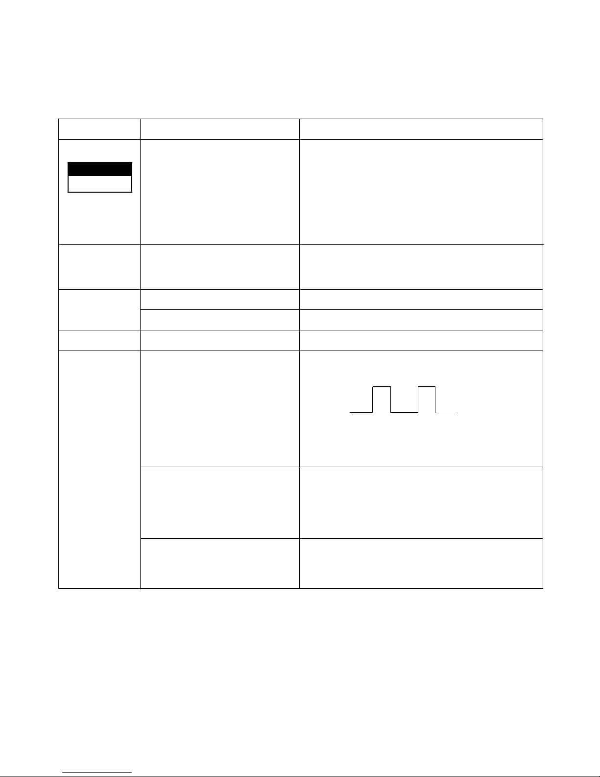
- 53 -
8. The phenomena in case of connecting error
INDOOR UNIT
Connector Type
Condition
Open and connecting error
Open
Open
Open
Open
Short between terminals
(③ and ④) of ROOM-TH.
Short between terminals
(① and ②) of PIPE-TH.
Short between terminals
• The same as the phenomenon of Outdoor Unit.
• The up/down vane does not operate.
• The up/down vane does not smoothly operate.
• It does not operate with a remote controller.
• The operation indicator blinks once
(on for 0.5 second, off for 3 seconds).
• The compressor operates continuously regardless
of the setting temperature and the variation of room
temperature.
• The operation indicator blinks once
(on for 0.5 second, off for 3 seconds)
• Continuous operation
• The operation indicator blinks once.
• The compressor and the outdoor fan stop.
• The indoor fan speed is low.
• The indoor fan does not operate.
• The operation indicator of Indoor unit blinks 8 times.
CN-DC/DC
CN-MOTOR
CN-UP/DOWN
CN-DISP
CN-TH
① Blue
② Black
③ Brown
④ Red
Phenomena
①②③④⑤
On for 0.5 second
Off for 3 seconds
Page 54

- 54 -
OUTDOOR UNIT
Connector Type
Condition
OPEN
• PWB pattern is damaged when applying the power.
Connecting reversely
Connecting reversely
OPEN
OPEN
OPEN
OPEN
Connecting error
(①↔②)
Connecting error
(①↔③)
Connecting error
(①↔④)
Connecting error
(②↔③)
Connecting error
(②↔④)
Connecting error
(③↔④)
• All functions stop.
• The operation with the remote controller, forced and
test one do not operate.
• All functions stop.
• The operation with the remote controller, forced and
test one do not operate.
• The Indoor Fan does not operate.
• The signal of remote controller is inputted, but the
product does not operate.
• The RED indicator of outdoor unit and the operation
indicator of indoor one blinks 5 times after 2 minutes
with applying the power.
• No power for Indoor unit.
• The signal input of the remote controller and operation of product is impossible.
• The thermal protector of the Power Trans operates
when let it alone for long time.
• The signal of the remote controller is inputted.
• The fuse and Q61 in the Outdoor unit are damaged
when the indoor fan is operated.
• No power for Indoor unit.
• The signal input of the remote controller and operation of product is impossible.
• The RED indicator of the Outdoor unit blinks 5 times
after 2 minutes with applying the power.
• All functions stop.
• The operation with the remote controller, forced and test
one do not operate.
• The only signal of remote controller operation/stop is
inputted, but the product does not operate.
• The RED indicator of outdoor unit blinks 5 times after 2
minutes with applying the power.
• The beep sound, such as "beep, beep, beep, beep,
beep", occurs periodically in Indoor unit.
• The signal input of a remote controller and operation of
product is impossible.
• The RED indicator blinks 5 times after 2 minutes with
applying the power.
• All functions stop or the compressor does not operate.
• The operation with the remote controller, forced and test
one do not operate.
• All functions stop.
• The operation with the remote controller, forced and test
one do not operate.
CN-POWER
RY-COMP
terminal
CN-TRANS
CN-FAN
The connecting
wire of CN-
DC/DC, and
Indoor and
Outdoor Unit
④③②①
① Blue
② Black
③ Brown
④ Red
Phenomena
Page 55

9. Voltage of Connectors according to Indoor Fan Speed
- 55 -
1 2 3 4
4
3
2
1
1 1
4
3
1 2 3 4 5
2 3 4 5 62
INDOOR
FAN
MOTOR
INDOOR PWB ASSY
Connecting wires
between Indoor
and Outdoor
Indoor
Connecting Terminal
Outdoor
Connecting Terminal
Input Power
POWER
TRANS
CN-POWER
CN-MOTOR
CN-TRANS
CN-DC/DC
CN-DC/DC
RY-COMP
BK
BL BK BR RD
BK BL
BL
BK
BR
RD
+
-
S-Hi Hi Med Low Off S-Hi Hi Med Low Off S-Hi Hi Med Low Off S-Hi Hi Med Low Off
1 2 28.6 25.6 22.2 20.0 0.0 35.7 30.7 25.1 21.2 0.0 32.0 27.8 24.1 21.2 0.0 35.7 33.3 29.4 24.2 0.0
3 2 5.0 5.0 5.0 5.0 5.0 5.0 5.0 5.0 5.0 5.0 5.0 5.0 5.0 5.0 5.0 5.0 5.0 5.0 5.0 5.0
4 2 0~5 0~5 0~5 0~5 5.0 0~5 0~5 0~5 0~5 5.0 0~5 0~5 0~5 0~5 5.0 0~5 0~5 0~5 0~5 5.0
1 2 0~12 0~12 0~12 0~12 0~12 0~12 0~12 0~12 0~12 0~12 0~12 0~12 0~12 0~12 0~12 0~12 0~12 0~12 0~12 0~12
3 2 17.0 17.0 17.0 17.0 17.0 17.0 17.0 17.0 17.0 17.0 17.0 17.0 17.0 17.0 17.0 17.0 17.0 17.0 17.0 17.0
4 2 28.6 25.6 22.2 20.0 0.0 35.7 30.7 25.1 21.2 0.0 32.0 27.8 24.1 21.2 0.0 35.7 33.3 29.4 24.2 0.0
1 2 0~12 0~12 0~12 0~12 0~12 0~12 0~12 0~12 0~12 0~12 0~12 0~12 0~12 0~12 0~12 0~12 0~12 0~12 0~12 0~12
3 2 17.0 17.0 17.0 17.0 17.0 17.0 17.0 17.0 17.0 17.0 17.0 17.0 17.0 17.0 17.0 17.0 17.0 17.0 17.0 17.0
4 2 29.0 25.9 22.4 20.2 0.0 36.0 30.9 25.3 21.3 0.0 32.3 28.1 24.4 21.3 0.0 36.0 33.7 29.6 24.4 0.0
24K
OUTDOO
R CN-
DC/DC
INDOOR
CN-
DC/DC
INDOOR
CN-
MOTOR
No. of pins
MODELS
CONNELTORS
9K 12K 18K
DC Voltage(±10%)DC Voltage(±10%) DC Voltage(±10%) DC Voltage(±10%)
Page 56

(1) MAIN PWB ASSY(Indoor Unit)
• PWB ASSY SVC PART LIST
- 56 -
Electronic Control Device
1 24K Heating Model 6871A10035A OPEN 56K 3K OPEN OPEN OPEN
2 24K Cooling Model 6871A10035B 12K 56K 3K OPEN OPEN OPEN
3 18K Heating Model 6871A10035C OPEN 56K 6.8K OEPN OPEN OPEN
4 18K Cooling Model 6871A10035D 12K 56K 6.8K OPEN OPEN OPEN
5 12K Heaing Model 6871A10035E OPEN 56K 2K OPEN OPEN OPEN
6 12K Cooling Model 6871A10035F 12K 56K 2K OPEN OPEN OPEN
7 9K Heating Model 6871A10035G OPEN 56K 15K OPEN OPEN OPEN
8 9K Cooling Model 6871A10035H 12K 56K 15K OPEN OPEN OPEN
NO MODEL P/No.
OPTIONAL FUNCTION
OR1H OR2H OR3H OR4H OR5H OR6H
OJ1H, OJ2H : OPEN
OJ3H, OJ4H : Short
Page 57

1 12K Heaing Model 6871A10036E 6.8K 5.1K 1K OPEN 39K O O O O O O
2 12K Cooling Model 6871A10036F 6.8K 5.1K 1K OPEN 39K X X X X X X
3 9K Heaing Model 6871A10036G 6.8K 10K 6.8K 3K OPEN O O O O O O
4 18K Heaing Model 6871A10036C 6.8K 10K 5.1K 6.8K 12K O O O O O O
5 18K Cooling Model 6871A10036D 6.8K 10K 5.1K 6.8K 12K X X X X X X
6 24K Heaing Model 6871A10036A 3K 2K 6.8K OPEN 3K O O O O O O
7 24K Cooling Model 6871A10036C 3K 2K 6.8K OPEN 3K X X X X X X
8 9K Cooling Model 6871A10036H 6.8K 10K 6.8K 3K OPEN X X X X X X
- 57 -
(2) MAIN PWB ASSY(Outdoor Unit)
• PWB ASSY SVC PART LIST
NO MODEL P/No.
OPTIONAL FUNCTION
OR4H OR5H OR6H OR7H OR 8H FUSE
RY-
HEATER
RY-
4WAY
RY-FAN
CN-
4WAY
CNFAN
CN-TH
125V
3.15A
250V
3.15A
Page 58

(3) DISPLAY PWB ASSY
- 58 -
<9K, 12K, 18K, 24K>
(P/No: 6871A30009C)
Page 59

1. Indoor Unit
- 59 -
Schematic Diagram
64
17
12
16
14
15
13
Operation
CMP
Timer
Sleep
7
9
8
11
10
4
6
5
3
2
1
37
31.
24
19
22
23
20
21
18
25
26
29
27
28
30
32
33
35
34
36
50
57
62
61
63
59
58
60
56
54
55
52
53
51
41
40
42
38
39
45
44
43
47
46
49
48
POLY SW
RXE250
Option
C04D
DC12V
Vss0
Vdd0
SW01F
CN-SW
Option
SWITCH
LIMIT
NO
NC
COM
321
321
FORCED OPERATION
REMOTE CONTROL
AUTO RESTART
312
4
5V
C05D
25V
470uF
C06D
103
+
104
50V
OJ2H
DC5V
R11H
OJ1H
7805
IC02D
O
I
OJ4HOJ3H
R11H~R14H
20K
20K
R06F
5V
20K
R04F
20K
R02F
8
ST93C46CB6
567
R12H
R14H
R13H
EEPROM
93C46B
S
VccQVss
D
C
ORG
DU
1
2
4
3
5V
CN-U/D
10V
220
C02L
CN-DISP
RECEIVER
Vcc
Vout
GND
11
625
4
LED1
LED4
LED3
2
6
4
5
3
7
1
LED2
RD
7
3
1
324
YL
OR
PK
324
(UP/DOWN)
5
BL
5
13
10
12
16
14
15
receiver
11
R01G~R04G
220
9
6
7
4
5
3
2
5V
KID65004AF
KID65004AF
IC01G
1
8
IC01M
9
HVB OUT
8
5
6
7
4
1
2
3
1
R02A,20K
5V
R11H~R16H
12.1K
DC 5V
C02D
+
C03D
25V
470uF
C01D
35V
2200uF
+
104
50V
7812
IC01D
O
I
3
10K
R97
10K
2
R96
IC9-1
KA393
-
4
DC12V
+
8
1
R95
10K
RESET
AVdd
AVref
OR6H
Hi Med
OR5H
AV1dd
5V
ssA
V
OR1H
O/L
OR3HOR4H
Low
F2
OR2H
F1
R21H
R26H
R25H
R24H5VR23H
R22H
C01A
25V
0.01
C02A
220
10V
3
DC 5V
CN-MOTOR
MOTOR
INDOOR
FAN
34
34
1
1
2
2
63V
100uF
+
~
C07D
1%
IC01A
KIA7036P
KSC7536
2
3.6V
10K
DC12V
R05H
R02H
R04H
1%
6.2K
1%
12.1K
5V
PKM13EPP-4002
BZ01E
CST-8.00MTW
receiver
16
Z
7
10
B
6
11
45
1312
132
14 15
R81 1K
R01B,1M
X1X2Vss15VINT0
INT1
103
C81
R01E
1K
R02L,1K
5V
R01L
5.1K
KID65004AF
IC02M
8
9
C01L 680pF
50V
R02E,20
CN-L/R
(LEFT/RIGHT)
BL
2
2
OR
PK
YL
3
4
3
4
RD
5
1
1
5
STEPPING MOTOR
Option
R90 1K
DC 5V
5V
OSC01B
103
C91
7
IC9-2
KA393
-
5
4.7K
R91
+
R92 10K
6
R93 10K
HVB OUT
12V
3333
CN-DC/DC
4
5
4
5
4 4
PIPE-TH
R99
C92
750
1/4W
104,50V
1
2
1
2
11
CN-TH1
3422
4
3
ROOM-TH
2
1
2
1
HVB OUT
CN-HVB
321
321
Page 60

2. Outdoor Unit
- 60 -
3
2
1
IC9
IC10
5
TLP521-1BL
TLP521-1BL
CN-DC/DC
4
2
3
1
470uF
20V
C05
4
2
3
1
8
2
3
220
VR71
R75
23.2K
1%
2K
100uF
25V
C73
+
4
R74
5.1K
8
7
29.4K
20K
34K
1.06K
102
1
-
+
-
D92
C92
50V
1N4148
8
104
IC7
5.23K 13K3K
3
+
14
9
HCP6068
56
R95
D91
1N4148
3
4
2
1
2
1
3
4
2.7K
R92
DC 5V
DC 5V
DC 5V
ZD81
5.1V
R91
1K
6.8K
1%
R82
R81
XXX
1%
NTC1
DKS-80-13
ZNR1
INR14D471K
35V
2200uF
+
103
C06
470uF
25V
C03
+
104
C02
50V
103
C04
C01
+
C66
63V
2SD2220
680uF
IC3
7805
100K
R68
5V
O
I
10K
R64
Q62
C67
100V
473K
+
R67
I
1.5K
7812
IC2
O
12V
103K
100V
C60
4 9
17V
102J,100V
C69C68
821K,1KV
C65
2
3
7
ST2
8
4
4
POWER TRANS
9 1
356 4
7
56 34
1
3
CN-TRANS
1
S1VB60
BD01
C62
1KV
222K
R65
D61 ERB44-08
30,1W
Q61
2SK2671
ZD61
12V
R66
200
101K
1KV
C63
68K
3W
R63
R62
1/2W
560K
100uF
+
C61
450V
AC230V/60Hz
FUSE
250V/3.15A
150-F06M
COIL1
CN-POWER
11
G4A-1A
RY-COMP
WXE-334K
N/FILTER1
33
RY-FAN,4WAY,HEATER
RY-4WAY,G5N-1A
RY-HEATER
RY-FAN
G5N-1A
COIL2
LS404060
CN-4WAY
CN-FAN
3
4
3
4
11
3
1
3
1
GMS81C1408SK(HYUNDDAI:8K)
TMR20V/RB7
SRDYIN/SRDYOUT/RC3
AN0/Aref/RB0
PWM0/COMP0/RB4
PWM1/COMP1/RB5
R97 1K
RY-HEATER
RY-COMP
RY-FAN
R96 620
RY-4WAY
10
6
100V
102J
C72
R73
13K
1%
1
6.04K
22
51.1K
2
-
4
5
-
+
L61
L62
FMX12S
L63
L64
D62
11
ST1
2
100Uf
R72
11K
1%
C71
+
25V
10.2K
1%
LED92
7
21.5K
39.2K
35.7K
+
11
4.3K
13
103
C91
R94
180
R93
390
1K
R90
LED91
DC12V
KRA102M
DC 5V
R71
Q71
13
9 9
8
15
16
2
1
12
13
14
11
4
3
5
6
MICOM
14
IC01M
KID65004APKID65004AP
111210
EC1/RB6
8
9
6
7
INTO/RB2
INT1/RB3
BUZ/RB2
12.1K
R27
1%
OR7
OR8
1%
XXX XXX
1%
R28
12.1K
1%
OR5
OR4 OR6
XXX
1%
XXX
1% 1%
XXX
12.1K
R25
R24
12.1K
1%
12.1K
1% 1%
R26
DC 5V
TH1
1K
R32H
R31H
12.1K
2
453
AN7/RA7
Vdd
AN6/RA6
AN5/RA5
1
AN4/RA4
DC 5V
+
R02A
10K
16
BD61
U4SBA60
RC4/SCK
RC5/SIN
15
21
171918
20
23
22
Xout
RC6/SOUT
RD2
Xin
RD0/INT2
RESET
Vss
R01B 1M
R01A
C01A
103
1K
50V
CST-4.00MTW
OSC01B
7036P
R03A
100
C02A
10uF
IC4
DC 5V
25
24
26
28
27
RD1/INT3
RA0/EC0
RA1/AN1
RA2/AN2
RA3/AN3
10K
C11H
103
R11H
10K
KEY
TEST
R12H
DC 5V
Page 61

1. Indoor Unit (9K)
- 61 -
Exploded View and Replacement Parts List
267110
249951
354212
135312
135311
359011
131410 733010
342800
268712
152302
159901
263230
268714
352150
346810
35211B
135314
146811
Page 62

- 62 -
Parts List(9K)
131410 CHASSIS ASSY 3141A20001B 1 1 R
135311 GRILLE ASSY,DISCHARGE(INDOOR) 3531A10005M 1 1 R
135312 GRILLE ASSY,FRONT(INDOOR) 3531A10073 1K 1B R
135314 GRILLE ASSY,INLET SUB 3531A20031 1Z 1Y R
146811 MOTOR ASSY,STEP 4681AR2727H 1 1 R
152302 FILTER(MECH),A/C 5230AR2630A 2 2 R
159901 VANE,HORIZONTAL 5990AR7225A 1 1 R
249951 CONTROL BOX ASSY,INDOOR 4995A20009 1T 1U R
263230 THERMISTOR ASSY 6323A20003A 1 1 R
267110 REMOTE CONTROLLER ASSY
6711A20025G 1 R
6711A20025M 1 R
268712 PWB(PCB) ASSY,DISPLAY 6871A30009C 1 1 R
268714 PWB(PCB) ASSY,MAIN 6871A10035 1H 1G R
342800 BEARING 3H02821B 1 1 R
346810 MOTOR ASSY,DC 4681AR2295G 1 1 R
35211B TUBE ASSY,TUBING 5211AR7288G 1 1 R
352150 HOSE ASSY,DRAIN 5251AR2575A 1 1 R
354212 EVAPORATOR ASSY,FINAL 5421AR6176V 1 1 R
359011 FAN ASSEMBLY,CROSS FLOW 5901AR6141A 1 1 R
733010 PLATE 3300A10002A 1 1 R
LOCATION
PART NAME PART NO.
"REMARKS("R"
means service parts)
Q'TY
HMC009KD1 HMH009KD1
Page 63

2. Indoor Unit(12K)
- 63 -
267110
249951
354212
135312
135311
359011
131410 733010
342800
268712
152302
159901-2
159901-1
263230
268714
352150
346810
35211B
135314
146811
Page 64

Parts List(12K)
- 64 -
131410 CHASSIS ASSY 3141A20003D 1 1 R
135311
GRILLE ASSY, DISCHARGE(INDOOR)
3531A10023T 1 1 R
135312 GRILLE ASSY, FRONT 3531A10030 1Y 1Z R
135314 GRILLE ASSY, INLET 3531A10032 1W 1X R
146811 MOTOR ASSY, STEP 4681AR2727H 1 1 R
152302 FILTER(MECH), A/C 5230A20004A 2 2 R
159901-1
VANE,HORIZONTAL 5990A30006A 1 1 R
159901-2
VANE,HORIZONTAL 5990A30007A 1 1 R
249951
CONTROL BOX ASSY, INDOOR
4995A20143 1N 1P R
263230 THERMISTOR ASSY 6323A20003A 1 1 R
267110
REMOTE CONTROLLER ASSY
6711A20025M 1 1 R
268712 PWB(PCB) ASSY, DISPLAY 6871A30009E 1 1 R
268714 PWB(PCB) ASSY, MAIN 6871A10035 1F 1E R
342800 BEARING 3H02821B 1 1 R
346810 MOTOR ASSY, DC 4681AR2295H 1 1 R
35211B TUBE ASSY, TUBING 5211AR7066B 1 1 R
352150 HOSE ASSY, DRAIN 5251AR2575A 1 1 R
354212 EVAPORATOR ASSY, FINAL 5421A20031X 1 1 R
359011 FAN ASSY, CROSS FLOW 5901AR6141C 1 1 R
733010 PLATE ASSY, INSTALL 1H00843A 1 1 R
LOCATION
PART NAME PART No.
Q/TY
HMC012KD1 HMH012KD1
REMARKS
("R" means
service parts)
Page 65
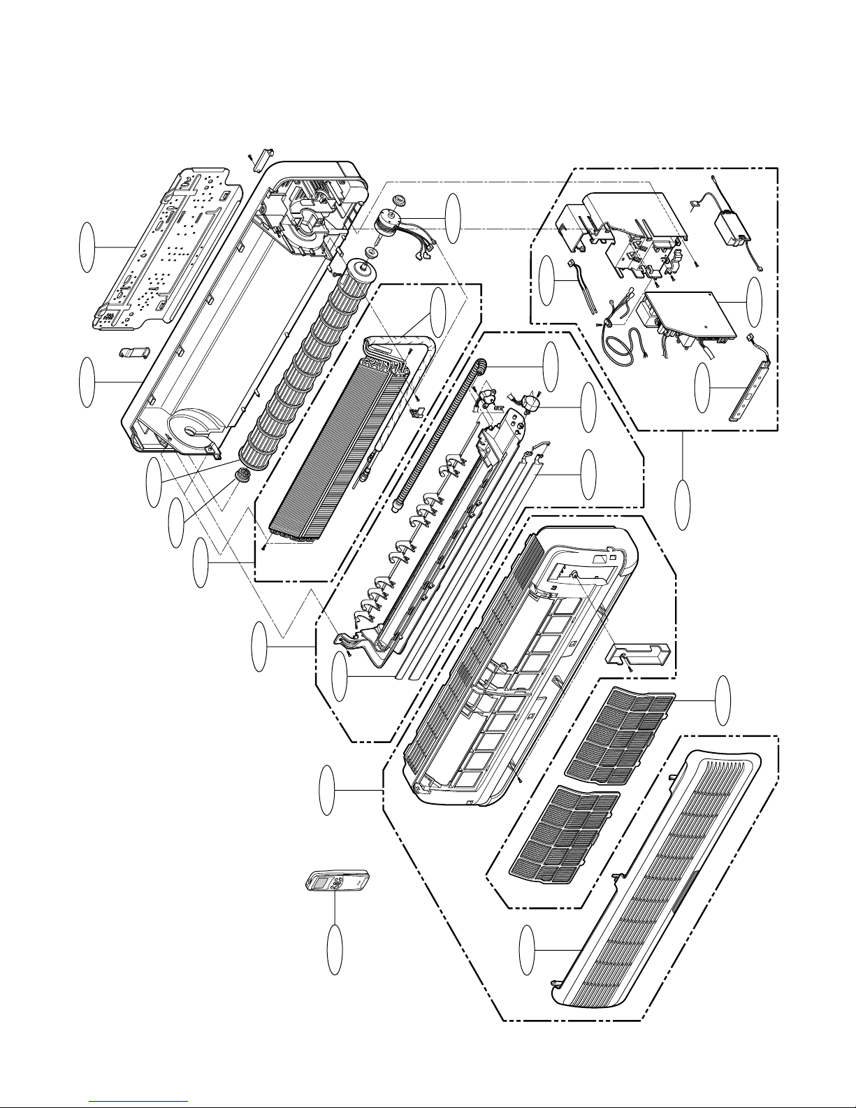
- 65 -
2. Indoor Unit(18K, 24K)
131410
267110
249951
135312
135311
354212
359011
733010
342800
268712
152302
159901-2
159901-1
263230
268714
352150
346810
146811
146811
135314
Page 66

- 66 -
Parts List(18K, 24K)
131410 CHASSIS ASSY 3141A20002D 1 1 1 1 R
135311
GRILLE ASSY, DISCHARGE(INDOOR)
3531A10008R 1 1 1 1 R
135312
GRILLE ASSY, FRONT(INDOOR)
3531A10026 1X 1Y 1X 1Y R
135314 GRILLE ASSY, INLET SUB 3531A20032 1R 1S 1R 1S R
146811 MOTOR ASSY, STEP 4681AR2727H 1 1 1 1 R
152302 FILTER(MECH), A/C 5230A20001A 2 2 2 2 R
159901-1
VANE, HORIZONTAL 5990A30001A 1 1 1 1 R
159901-2
VANE, HORIZONTAL 5990A30002A 1 1 1 1 R
249951
CONTROL BOX ASSY, INDOOR
4995A20123 1U 1V 1W 1X R
263230 THERMISTOR ASSY 6323A20003A 1 1 1 1 R
267110
REMOTE CONTROLLER ASSY
6711A20025M 1 1 R
6711A20026T 1 1 R
268712 PWB(PCB) ASSY, DISPLAY 6871A30009D 1 1 1 1 R
268714 PWB(PCB) ASSY, MAIN 6871A10035 1D 1C 1B 1A R
342800 BEARING 3H02821B 1 1 1 1 R
346810 MOTOR ASSY, DC 4681AR2295J 1 1 1 1 R
35211B TUBE ASSY, TUBING 5211A30038 1C 1C 1D 1D R
352150 HOSE ASSY, DRAIN 5251AR2575A 1 1 1 1 R
354212 EVAPORATOR ASSY, FINAL 5421A20021 1D 1T 1E 1E R
359011 FAN ASSY, CROSS FLOW 5901AR2441 1D 1E 1D 1E R
733010 PLATE ASSY, INSTALL 1H00843A 1 1 1 1 R
LOCATION
PART NAME PART No.
Q/TY
HMC018KD1 HMH018KD1 HMC024KD1 HMH024KD1
REMARKS
("R" means
service parts)
Page 67

- 67 -
550140
554160
567502
552116
561410
553000
552111
437210
559010
546810
554031
261704
W0CZZ
430410
552203-3
552203-1
437212
435511
552202
649950
668711
4. Outdoor Unit(9K, 12K)
Page 68

Parts List(9K, 12K)
- 68 -
552116 TUBE ASSY,REVERSING 5211A20140 1F 1G R
552202 VALVE,REVERSING 5220AR3084B 1 1 R
552203-1 VALVE,SERVICE 2H02479H 1 1 R
5220A20005A 1 1 R
552203-3 VALVE,SERVICE 2H01890L 1 1 R
5220A20003A 1 1 R
553000 HEATER,SUMP 5300AR2915D 1 1 R
554031 CONDENSER ASSY,BENT 5403A20019 1B 1P R
5403A20026 1D 1B R
554160 COMPRESSOR SET 2520UKAC2BA 1 R
2520UKWC2FA 1 R
2520UKCC2AA 1 R
2520UKSC2AA 1 R
559010 FAN ASSY,PROPELLER 5901A10004A R
561410 COIL ASSY,REVERSING VALVE 6141AR3851G 1 1 R
567502 O.L.P 6750U-L029A 1 R
6750U-L031A 1 R
6750U-L046A 1 R
6750U-L049A 1 R
649950 CONTROL BOX ASSY,OUTDOOR 4995A10038 1A 1B 1C 1D R
668711 PWB(PCB) ASSEMBLY,MAIN(OUTDOOR) 6871A10036 1H 1G 1F 1E R
W0CZZ CAPACITOR,DRAWING 0CZZA20001 1N 1L R
6120AR2194 1F 1K R
552111 TUBE ASSY,CAPILLARY 5211A20095F 1 R
5211A20141 1A 1D R
5211A20133D 1 R
261704 TRANSFORMER,POWER 6171AQ3198B 1 1 1 1 R
430410 BASE ASSY,OUTDOOR 3041A20008 1J 1F 1D 1F R
435511 COVER ASSY,CONTROL(OUTDOOR) 3551AR7184R 1 1 1 1 R
437210 PANEL ASSEMBLY,FRONT(OUTDOOR) 3721A20027B 1 1 1 1 R
437212 PANEL ASSY,REAR(OUTDOOR) 3721A20026 1A 1B 1A 1B R
546810 MOTOR ASSY,OUTDOOR 4681A20004R 1 1 1 1 R
550140 ISOLATOR,COMP 4H00982E 3 3 3 3 R
LOCATION
PART NAME PART NO.
"REMARKS("R"
means service parts)
Q'TY
HMC009KD1 HMH009KD1 HMC012KD1 HMH012KD1
Page 69

5. Outdoor Unit(18K)
- 69 -
552116
649950
561410
554160
567502
447910
550140
552203-2
552203-3
435512
437210
559010
546810
668711
552111
W0CZZ
554031
261704
437212
435511
553000430411
Page 70

Parts List(18K)
- 70 -
261704 TRANSFORMER, POWER 6171AQ3178A 1 1
430411
BASE ASSY, WELD(OUTDOOR)
3041A30003F 1 1 R
435511
COVER ASSY, CONTROL(OUTDOOR)
3551AR7184T 1 1 R
435512
COVER ASSY, TOP(OUTDOOR)
3H03266J 1 1 R
437210
PANEL ASSY, FRONT(OUTDOOR)
3721A20005B 1 1 R
437212 PANEL ASSY, REAR 3720AP0003D 1 1 R
546810 MOTOR ASSY, OUTDOOR 4681A20013M 1 1 R
550140 ISOLATOR, COMP 4H00982E 3 3 R
552111 TUBE ASSY, CAPILLARY 5425AR3847L 1 R
5211A10039B 1 R
552116 TUBE ASSY, REVERSING 5211A30042J 1 R
552202 VALVE, REVERSING 3A02027D 1 R
552203-2
VALVE, SERVICE 2A00392E 1 1 R
552203-3
VALVE, SERVICE 2H02479 1B 1F R
553000 HEATER, SUMP 5300AR2915A 1 R
554031 CONDENSER ASSY, BENT 5403A20022 1B 1F R
554160 COMPRESSOR SET 2520UMLK1BA 1 R
2520UMBK1BA 1 R
559010 FAN ASSY, PROPELLER 1A00195B 1 1 R
561410
COIL ASSY, REVERSING VALVE
3A02028H 1 R
567502 O.L.P 6750U-L025A 1 R
649950
CONTROL BOX ASSY, OUTDOOR
4781AR1528 1Q 1R R
668711
PWB(PCB) ASSY, MAIN(OUTDOOR)
6871A10036 1D 1C R
W0CZZ CAPACITOR, DRAWING 6120AR2194 1B 1F R
LOCATION
PART NAME PART No.
Q/TY
HMC018KD1 HMH018KD1
REMARKS
("R" means
service parts)
Page 71

5. Outdoor Unit(24K)
- 71 -
649950
552111
668711
W0CZZ
550140
553000
552116
552202
561440
552203-3
552203-1
435511
430411
435512
554031
437212
437210
559010
546811
554031
261704
Page 72

Parts List(24K)
- 72 -
261704 TRANSFORMER, POWER 6171AQ3198A 1 1 R
430411
BASE ASSY, WELD(OUTDOOR)
3041A30003U 1 1 R
435511
COVER ASSY, CONTROL(OUTDOOR)
3551AR7184T 1 1 R
435512
COVER ASSY, TOP(OUTDOOR)
3H03266J 1 1 R
437210
PANEL ASSY, FRONT(OUTDOOR)
3721A20005B 1 1 R
437212 PANEL ASSY, REAR 3720AP0003D 1 1 R
546811 MOTOR ASSY, OUTDOOR 4681A20013N 1 1 R
550140 ISOLATOR, COMP 4H00637A 3 R
5040A30017B 3
552111 TUBE ASSY, CAPILLARY 5425AR3847Q 1 R
5211A10039J 1 R
552116 TUBE ASSY, REVERSING 5221AR2938Y 1 R
552202 VALVE, REVERSING 3A02027D 1 R
552203-1
VALVE, SERVICE 2A00393C 1 1 R
552203-3
VALVE, SERVICE 2A00392E 1 1 R
553000 HEATER, SUMP 5300AR2915A 1 R
554031 CONDENSER ASSY, BENT 5402AR2347Z 1 R
5403A20051B 1 R
554160
COMPRESSOR ASSY, FINAL
5417A20012N 1 1 R
559010 FAN ASSY, PROPELLER 1A00195B 1 1 R
561440
COIL ASSY, REVERSING VALVE
3A02028H 1 R
649950
CONTROL BOX ASSY, OUTDOOR
4781AR1528 1S 1T R
668711
PWB(PCB) ASSY, MAIN(OUTDOOR)
6871A10036 1B 1A R
W0CZZ CAPACITOR, DRAWING 6120AR2359U 1 1 R
LOCATION
PART NAME PART No.
Q/TY
HMC024KD1 HMH024KD1
REMARKS
("R" means
service parts)
Page 73

P/No.: 3828A20048M Printed in Korea
 Loading...