

Page 1
N8MPN&N8MPL
*8MPN&*8MPL
* Denotes Brands (C, H, T)
See section 5 for Category I definition.
SAFETY REQUIREMENTS
Recognizesafetyinformation. Thisisthesafety--alertsymbol!. Whenyouseethissymbolon thefurnaceand ininstructionmanualsbealert
to the potential for personal injury.
Understand thesignalwordsDANGER,WARNING,orCAUTION. Thesewordsareusedwiththesafety--alert symbol. DANGERidentifiesthe
mostserioushazards,thosethat will resultinsevere personalinjuryordeath. WARNING signifies ahazardthat couldresultin personalinjuryor
death. CAUTION is used toidentify unsafepractices that couldresultinminorpersonalinjuryorproductandproperty damage. Note is usedto
highlight suggestions that will result in enhanced installation, reliability, or operation.
Installingandservicingheatingequipment can behazardousdue to gasandelectrical components. Onlytrainedand qualifiedpersonnelshould
install, repair, or service heating equipment.
Untrained service personnel can perform basic maintenance functions such as cleaning and replacing air filters. All other operations must be
performed by trained service personnel. When working on heating equipment, observe precautions in the literature, on tags, and on labels attached to or shipped with the furnace and other safety precautions that may apply.
Follow all safety codes. In the United States, follow all safety codes including the National Fuel Gas Code (NFGC) ANSI Z223.1--2002/NFPA
54--2002. InCanada,refertotheNational StandardofCanada Natural GasandPropaneInstallationCode(NSCNGPIC) CSAB149.1--00. Wear
safety glasses and work gloves. Have fire extinguisher available during start--up and adjustment procedures and service calls.
These instructions cover minimum requirements and conform to existing national standards and safety codes. In some instances, these
instructions exceedcertainlocalcodesandordinances,especiallythosethatmaynothavekeptupwithchangingresidential constructionpractices. We require these instructions as a minimum for a safe installation.
International Comfort Products, LLC
Lewisburg, TN 37091
INSTALLER: Affix these instructions
on or adjacent to the furnace.
CONSUMER: Retain these
instructions for future reference.
Ò
1. Safe Installation Requirements 3...............
2. Installation 4..............................
3. Side Venting 8.............................
4. Combustion & Ventilation Air 9................
5. Gas VentInstallation 12.......................
6. Horizontal Venting 14.........................
7. Masonry Chimney Venting 16...................
8. Gas Supply and Piping 19.....................
!
WARNING
ELECTRIC SHOCK HAZARD
Failure to follow safety warnings
exactly could result in serious
injury, death, and/or property
damage.
Turn Off All Power Before
Servicing.
Portions of the textand tables are reprinted from NFPA54 / ANSI Z223.1--2002ã, withpermission of National Fire Protection Association, Quincy, MA 02269 andAmerican Gas Association,
Washington, DC20001. This reprinted material isnot the complete and official position of the NFPA or ANSI,on the referenced subject, which is represented only by the standard in its entirety.
Printed in U.S.A. 10/19/2004 441 01 2611 (06)
Table of Contents
9. Electrical Wiring 22.........................
10.Ductwork and Filter (Upflow/Horizontal) 23.......
11.Ductwork and Filter (Downflow) 25.............
12. Checks and Adjustments 29...................
13. Furnace Maintenance 33.....................
14. Sequence of Operation & Diagnostics 34.........
TechSupport and Parts 37.......................
!
CARBON MONOXIDE POISONING AND FIRE
HAZARD.
Failuretofollowsafetywarnings exactly could
result in serious injury,death, and/or property
damage.
This furnace is not designed for use in mobile
homes, trailers or recreational vehicles.
WARNING
WARNING
Ò
Page 2
START--UP CHECK SHEET
(Keep this page for future reference)
Recommended, but not required. Checklist DOES NOT apply in Canada
Dealer Name:
Address: Business Card Here
City, State(Province), Zip or Postal Code:
Phone:
Owner Name:
Address:
City, State(Province), Zip or Postal Code:
Model Number:
Serial Number:
Type of Gas: Natural: LP:
Blower Motor H.P.:
Supply Voltage:
Limit Opens at...(°F) or(°C)
Limit Closes at...(°F) or(°C)
Which blower speed tap is used?
(Heating)
(Cooling)
Manual Gas Shut--Off Upstream
of Furnace/Drip--Leg? YES
Drip--Leg Upstream of Gas Valve? YES NO
Blower Speed Checked? YES NO
All Electrical Connections Tight? YES NO
Gas Valve OK? YES NO
Measured Line Pressure When Firing Unit:
Calculated Firing Rate:(See Checks and Adjustments
Section).
Measured Manifold Pressure:
Thermostat OK? YES NO
NO
Temperature of Supply Air: (°F) or(°C)
Temperature of Return Air: (°F) or(°C)
Rise (Supply Temp.--Return Temp.): (°F) or(°C)
Filter Type and Size:
Fan “Time ON” Setting:
Fan “Time OFF” Setting:
Dealer Comments:
2
Subbase Level? YES NO
Anticipator Set? YES NO Set At?:
Breaker On? YES NO
Date of Installation:
Date of Start--Up:
441 01 2611 06
Page 3
1. Safe Installation Requirements
!
WARNING
FIRE, EXPLOSION, AND ASPHIXIATION HAZARD
Improper adjustment, alteration, service,
maintance or installation could cause serious
injury, death and/or property damage.
Installationorrepairsmadeby unqualified persons
could result in hazards to you and others.
Installation MUST conform with local codes or, in
the absence of local codes, with codes of all
governmental authorities having jurisdiction.
The information contained in t his manual is
intended for use by a qualified service agency that
is experienced in such work, is familiar with all
precautions and safety procedures required in
such work, and is equipped with the proper tools
and test instruments.
NOTE: This furnace is design--certified by the CSA International
(formerly AGA and CGA) for installation in the United States and
Canada. Refer to the appropriate codes, along with this manual,
for proper installation.
· Use only the Type of gas approved for this furnace (see
RatingPlateon unit).Overfiringwill resultinfailure ofheat
exchanger and cause dangerous operation. (Furnaces
can be converted to LP gas with approved kit.)
· Installthisfurnaceonly in a location andpositionasspeci-
fied in “2. Installation” of these instructions.
· Provideadequatecombustionandventilationairtothefur-
naceasspecifiedin “4.CombustionandVentilationAir” of
these instructions.
· Combustionproductsmustbedischargedoutdoors.Con-
nectthisfurnacetoan approved vent systemonly,as specifiedin “5.GasVentInstallation,6.Horizontal Ventingand
7. Masonry Chimney Venting” of these instructions.
· Never test for gas leaks with an open flame. Use a com-
merciallyavailablesoapsolution made specifically for the
detectionofleakstocheckallconnections,asspecifiedin
“8. Gas Supply and Piping, Final Check” of these instructions.
· Always install furnace to operate within the furnace’s in-
tended temperature--rise range with a duct system which
hasanexternalstatic pressurewithintheallowablerange,
as specified in “Technical Support Manual” of these in-
structions.
· When a furnace is installed so that supply ducts carry air
circulated by the furnace to areas outside the space containingthe furnace,thereturnairshallalsobe handledbya
duct(s) sealed to the furnace casing and terminating outside the space containing the furnace.
· Agas--fired furnace for installation in a residential garage
must be installed as specified in “2. Installation” of these
instructions.
· This furnace is not to be used for temporary heating of
buildings or structures under construction.
See “2. Installation, Item 10”.
· This furnace is NOT approved for installation in mo-
bile homes, trailers or recreation vehicles.
· Seal around supply and return air ducts.
· Install correct filter type and size.
· Unit MUST be installed so electrical components are pro-
tected from direct contact with water.
Safety Rules
Your unit is built to provide many years of s afe and dependable
serviceprovidingit is properly installedandmaintained.However,
abuse and/or improper use can shorten the life of the unit and
create hazards for you, the owner.
A. The U.S. ConsumerProduct Safety Commission encourages
installation of carbon monoxide alarms. There can be various
sources of carbon monoxide in a building or dwelling. The
sources could be gas--fired c lothes dryers, gas cooking
stoves, water heaters, furnaces, gas--fired fireplaces, wood
fireplaces, and several other items.
Carbon monoxide can cause serious bodily injury and/or
death. Carbon monoxide or “CO” is a colorless and odorless
gas produced when fuel is not burned completely or whenthe
flame does not receive sufficient oxygen.
Therefore,tohelpalertpeopleofpotentiallydangerouscarbon
monoxide levels, you should have a commercially available
carbon monoxide alarm that is listed by a nationally recognizedtestingagencyinaccordancewithUnderwritersLaboratories Inc. Standard for Single and Multiple Station Carbon
Monoxide Alarms, ANSI/UL 2034 or the CSA 6.19--01 Residential Carbon Alarming Devices installed and maintained in
thebuildingordwellingconcurrentlywiththegas--firedfurnace
installation(seeNote below).Thealarm shouldbeinstalledas
recommended by the alarm manufacturer’s installation instructions.
B. There can be numerous sources of fire or smokein a building
or dwelling. Fire or smoke can cause serious bodily injury,
death, and/or property damage. Therefore, in order to alert
peopleofpotentiallydangerousfireorsmoke,youshouldhave
fireextinguisherandsmokealarmslistedbyUnderwritersLaboratories installed and maintained in the building or dwelling
(see Note below).
Note: The manufacturer of your furnace does not test any alarms
and makes no representations regarding any brand or type
of alarms.
C. To ensure safeandefficientoperationofyourunit,youshould
do the following:
1. Thoroughly read this manual and labels on the unit. This
will help you understand how your unit operates and the hazards involved with gas and electricity.
2. Do not use this unit if any part has been under water. Immediatelycallaqualifiedserviceagencytoinspecttheunitand
to replace any part of the control system and any gas control
which has been under water.
3. Never obstruct the vent grilles, or any ducts that provide
airto theunit.Airmustbeprovidedforpropercombustionand
ventilation of flue gases.
441 01 2611 06
3
Page 4
Frozen Water Pipe Hazard
Ifyour furnace remains off for an extended time, the pipes in your
home could freeze and burst, resulting in serious water damage.
!
WARNING
FROZEN AND BURST WATER PIPE HAZARD
FaiIure to protect against the risk of freezing could
result in property damage and/or personal injury.
Donotleaveyourhomeunattendedforlongperiods
during freezing weather without turning off water
supply and draining water pipes or otherwise
protecting against the risk of frozen pipes and
resultant damage.
Yourfurnaceisdesignedsolelytoprovidea safe and comfortable
living environment. The furnace is NOT designed to ensure that
water pipes will not freeze. It is equipped with several safety devices that are designed to turn the furnace off and prevent it from
restarting in the event of various potentially unsafe conditions.
2. Installation
!
CARBON MONOXIDE POISONING HAZARD.
Failure to properly vent this furnace or other
appliances could result in death, personal injury
and/or property damage.
If this furnace is replacing a previously commonvented furnace, it may be necessary to resize the
existing vent system to prevent oversizing
problems for the other remaining appliances(s).
SeeVentingand CombustionAirCheckinthe5.Gas
Vent Installation section of this instruction.
Location and Clearances
If furnace is a replacement, it is usually best to install the furnace
wheretheoldone was. Choose the location or evaluate the existing location based upon the minimum clearance and furnace dimensions (Figure 1 or Figure 2).
!
CARBON MONOXIDE POISONING HAZARD.
Failure to follow safety warnings could result in
serious injury, death, or property damage.
Do NOT operate furnace in a corrosive
atmosphere containing chlorine, fluorine or any
other damaging chemicals which could harm the
furnace and vent system, and permit spillage of
combustion products into an occupied space.
Refer to 4. Combustion & Ventilation Air section,
Contaminated Combustion Air for combustion air
evaluation and remedy.
Installation Requirements
1. Install furnace level.
2. ThisfurnaceisNOT to be usedfortemporaryheat of buildings
or structures under construction.
3. Install furnace as centralized as practical with respect to the
heat distribution system.
4
WARNING
WARNING
If the structure will be unattendedduring cold weather you should
take these precautions.
1. Turnoffthewater supplytothe structureanddrain thewater
lines if possible and add an antifreeze for potable water to
drain traps and toilet tanks. Open faucets in appropriate
areas.
-- o r --
2. Have someone check the structure frequently during cold
weather to make sure it is warm enough to prevent pipes
from freezing. Instruct them on a service agency to call to
provide service, if required.
-- o r --
3. Installareliableremotesensingdevicethatwillnotifysomebody of freezing conditions within the home.
4. Install the vent pipes as short as practical. (See 5. Gas Vent
Installation section).
5. DoNOTinstallfurnacedirectlyoncarpeting, tileorothercombustible material other than wood flooring.
6. Maintain clearance for fire safety and servicing. A front clearanceof30² is minimum for access to the burner, controls and
filter. See clearance requirements in Figure 1 or Figure 2.
7. Use a raised base if the floor is damp or wet at times.
8. Residential garage installations require:
· Burners and ignition sources installed at least 18² (457
mm) above the floor.
· Furnace must be located or physically protected from
possible damage by a vehicle.
9. Ifthefurnace is tobesuspendedfromthefloorjoistsin abasementoracrawlspaceortheraftersinanattic,it isnecessaryto
use steel pipe straps or an angle iron frame to attach the furnace. These straps should be attached to the furnace bottom
side with sheet metal screws and to the rafters or joists with
bolts. The preferred method is to use an angle iron frame
bolted to the rafters or joists.
10. This furnace maybeusedforconstruction heat provided that:
· The furnace is permanently installed with all electrical
wiring,piping,ventingandductinginstalledaccordingto
these installation instructions. A return air duct is provided,sealed to the furnace casing, and terminated outside the space c ontaining the furnace. This prevents a
negativepressurecondition ascreatedbythe circulating
air blower, causing a flame rollout and/or drawing combustion products into the structure.
· The furnace is controlled by a thermostat. Itmay not be
“hot wired” to provide heat continuously to the structure
without thermostatic control.
· Clean outside air is provided for combustion. This is to
minimizethecorrosiveeffectsofadhesives, s ealers and
otherconstruction materials. Italsopreventstheentrainmentofdrywalldustintocombustionair,whichcancause
fouling and plugging of furnace components.
· The temperature of the return air to the furnace is main-
tained between 55° F(13° C) and 80° F(27° C) , with no
evening setback or shutdown. The use of the furnace
whilethestructureisunderconstruction is deemed to be
intermittent operation per our installation instructions.
441 01 2611 06
Page 5
· The air temperature rise is within the rated rise range on
Furnace
ReturnAir
thefurnace ratingplate,andthefiringratehasbeensetto
the rating plate value.
· The filters used to c lean the circulating air during the
construction process must be either changed or thoroughly cleaned prior to occupancy.
· The furnace, ductwork and filters are cleaned as neces-
sarytoremovedrywalldustandconstructiondebris from
all HVACsystemcomponentsafter construction is completed.
· Verifyproperfurnaceoperatingconditionsincluding igni-
tion,gas input rate, air temperature rise, and venting according to these installation instructions.
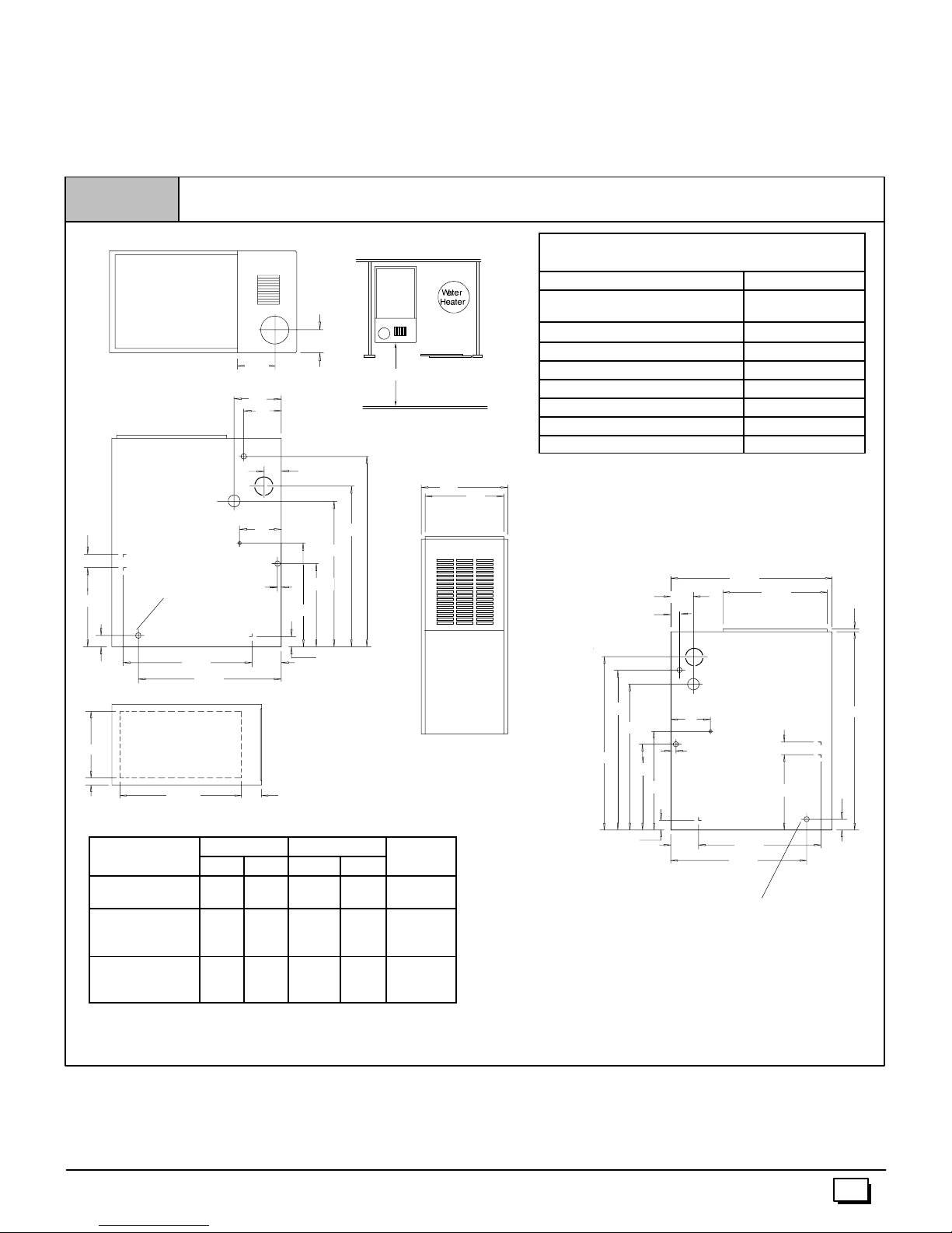
Figure 1
Dimensions and Clearances (N8MPN/L)
TOP
51/
3
61/
2
5
LEFT SIDE
7
21/
131/
4
4
17/
D
C
8
Plugged starting
hole tocutside
duct opening
213/
BOTTOM
231/
8
4
265/
1
47/
8
8
DIMENSIONAL INFORMATION
Furnace
Model
N8MPN/L050B12
N8MPN/L075B12
N8MPN/L075F16
N8MPN100F14
N8MPN/L100F20
N8MPN/L100J22
N8MPN/L125J20
N8MPN/L125J22
Cabinet Bottom
A B C D
151/
2 14
191/8175/
8
223/4211/4115/
MINIMUM CLEARANCES TO COMBUSTIBLE
REAR 0
FRONT (combustion air openings
in furnace and structure)
31/
4
30² Min.
33/
171/
131/
3
4
33
271/
2
241/
2
4
11/
2
A
B
FRONT
Drawing is representative, but some models may vary
41/
16
DIMENSIONS IN INCHES
Return Air
Opening
13/
21/
125/
8
143/
8
H
8
4
J
NOTE: Evaporator “A” coil drain pan dimensions may vary
183/
16
4
J
from furnace duct opening size. Always consult evaporator
specifications for duct size requirements.
Furnace is designed for bottom return or side return.
Return air through back of furnace is NOT allowed.
Required For Service
ALL SIDES Of SUPPLY PLENUM 1²
SIDES 0
VENT
Single--Wall Vent 6²
Type B--1 Double--Wall Vent 1²
TOP OF FURNACE 1²
*30² clearancerecommendedforcasing removal.
Horizontalposition: Linecontactis permissibleonlybetweenlines
formedbyintersectionsoftopandtwosidesof furnace jacket,and
buildingjoists, studsorframing.
MATERIALS FOR ALL FURNACES
3²
*24²
281/
2
181/
213/
2
21/
4
J
H
131/
4
4
8
33/
4
2
RIGHT SIDE
281/
2
253/
4
32
131/
11/
2
7
1
4
171/
3
47/
8
Plugged starting hole tocut
side duct opening
265/
3
/
4
35
17/
8
25--23--44a1
441 01 2611 06
5
Page 6

Figure 2
Furnace
ReturnAir
21/
4
131/
4
TOP
51/
LEFT SIDE
Plugged starting
hole tocutside
duct opening
Dimensions and Clearances (*8MPN/L Models)
F
3
5
1
33/
4
7337
277/
175/
16
271/
2
321/
8
30² Min.
A
B
2
38
FRONT
MINIMUM CLEARANCES TO COMBUSTIBLE
MATERIALS FOR ALL UNITS
REAR 0
FRONT (combustion air openings
3²
in furnace and structure)
Required For Service
*24²
ALL SIDES Of SUPPLY PLENUM 1²
SIDES 0
VENT
Single--Wall Vent 6²
Type B--1 Double Wall Vent 1²
TOP OF FURNACE 1²
*30² clearancerecommendedforcasing removal.
Horizontalposition: Linecontactis permissibleonlybetweenlines
formedbyintersectionsoftopandtwosidesof furnace jacket,and
buildingjoists, studsorframing.
281/
2
181/
33/
4
2
2
3
/
4
213/
17/
8
D
4
265/
BOTTOM
47/
8
11/
8
2
Drawing is representative some models may vary
231/
C
8
41/
16
DIMENSIONS IN INCHES
DIMENSIONAL INFORMATION
Furnace
Model
*8MPN/L050B12
*8MPN/L075B12
*8MPN/L075F16
*8MPN100F14
*8MPN/L100F20
*8MPN/L100J20
*8MPN/L125J20
*8MPN150J20
* Denotes Brand
Cabinet Top Bottom
A B F C D
151/214 6 13/8125/
191/8175/873/421/8143/
223/4211/491/2115/16183/
8
4
4
Return Air
Opening
H
J
J
NOTE: Evaporator “A” coil drain pan dimensions may
vary from furnace duct opening size. Always consult
evaporator specifications for duct size requirements.
Furnace is designed for bottom return or side return.
Return air through back of furnace is NOT allowed.
Furnace Installation
Inspecttheratingplatetobe certainthemodelnumberbegins with
“N8MP” or“*8MP”.Thisidentifies the unit as a multi--position furnaceandcan beInstalledina Upflow,HorizontalRight,Horizontal
Left or Downflow position.
RIGHT SIDE
1
37
303/
4
291/
1
/
2
175/
11/
2
7
J
21/
4
265/
H
131/
4
213/
4
8
Plugged starting hole to
cut side duct opening
2
16
47/
8
40
17/
8
Upflow
No modifications are required for upflow installation. (See
Figure 3)
6
441 01 2611 06
Page 7
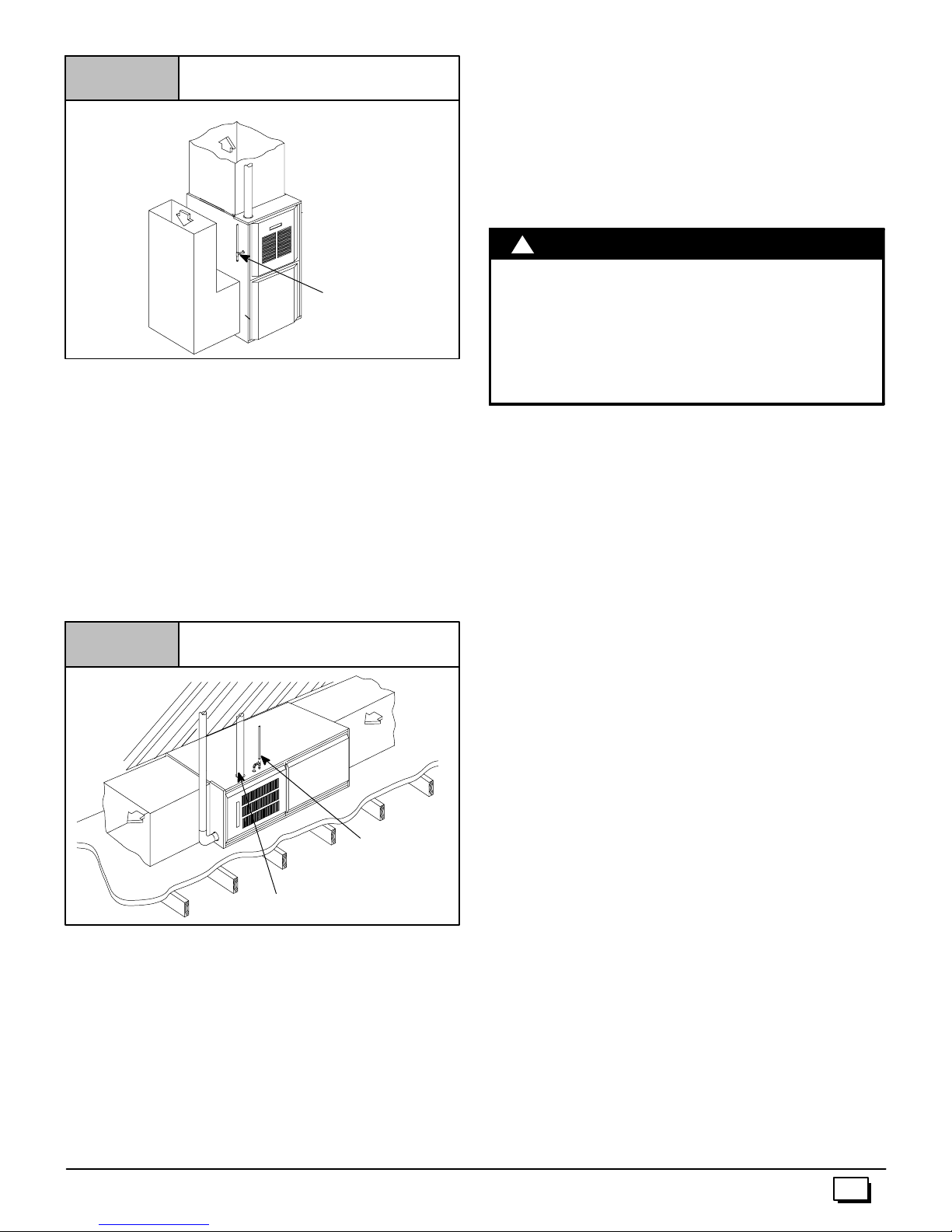
Figure 3
RETURN
AIR
T y pical Upflow Installation
SUPPLY
AIR
VENT
The horizontal furnaces may be installed directly on combustible
woodflooringorsupports, however,itisrecommendedforfurther
fireprotectioncementboardorsheetmetalisplacedbetweenthe
furnace and the combustible wood floor and extend 12² beyond
the front of the furnace louver door. (This is a recommendation
only, not a requirement).
This furnace MUST NOT be installed directly on carpeting, tile or
other combustible material other than wood flooring or supports.
Downflow
GAS SUPPLY
25--23--17
Horizontal
Ifyou purchased a multi--position furnace, it can be installed horizontallyin an attic, basement, crawl space, alcove, or suspended
from a ceiling in a basement or utility room in either a right or left
airflow position. (see Figure 4)
Horizontally installed furnaces may be vented out the top of the
unitoroutthesidefacingup.See“Sideventing” forinstructionsto
rotate the vent to the side.
The minimum clearances to combustibles MUST be maintained
between the furnace and adjacent construction, as shown in
Figure 1 and Figure 2. ONLYthecornerofthecabinetisallowed
to contact the rafters as shown in Figure 4. All other clearances
MUST be observed as shown in Figure 1 and Figure 2.
Figure 4
SUPPLY
AIR
Ifthe furnaceisto besuspendedfromthefloorjoistsina basement
orcrawlspaceortheraftersinanattic,itis necessary to use steel
pipe straps or an angle iron frame to attach the furnace. These
straps should be attached to the furnace bottom side with sheet
metal screws and to the rafters or joists with bolts. The preferred
methodistouse an angle iron frame bolted to the rafters orjoists.
Ifthefurnaceistobeinstalledatgroundlevelinacrawlspace,consult local codes. A concrete pad 1² to 2² thick is recommended.
Thirtyinches(30²)isrequiredbetween thefrontofthe furnaceand
adjacent construction or other appliances. This should be maintained for service clearance.
Keep all insulating materials clear from louvered door.Insulating
materials may be combustible.
441 01 2611 06
T ypical Horizontal Installation
RETURN
AIR
VENT
VENT
GAS SUPPLY
OPTIONAL
VENT LOCATION
25-23-18a
!
WARNING
FIRE HAZARD.
Failure to install unit on noncombustible subbase
couldresultin death, personalinjuryand/orproperty
damage.
Place furnace on noncombustible subbase on
downflow applications, unless installing on
noncombustible flooring.
If you purchased a Multi--position furnace (*8MP) it may be
installed in a downflow configuration, (see Figure 5). The minimumclearancestocombustionconstructionMUST bemaintained
between the furnace and adjacent construction, as shown in
Figure 1 and Figure 2.
In addition to clearances in Figure 1 and Figure 2, c learance for
the vent pipe must be considered.
AsubbaseforcombustiblefloorsMUST beusedwhenthefurnace
isinstalledasa downflowoncombustiblematerial. See 11.“Duct-
work and Filter” (Downflow Section). The outlet flange must be
bent flat for downflow installation.
When installing a four--position furnace in the downflow position
(not the *8DNL furnace), the logo is to be repositioned so that it is
rightside--up as follows:
T8MPN/L
1. Find the door hardware kit that is stored in the furnace and
save it.
2. Carefullyremovelogofromtheoutsideof burnercompartment
door and save it.
3. Carefullyremovetwosmallplugbuttonsfromoutsideofblower compartment door and save them.
4. Removetwo thumbscrews from blower compartment door by
cutting apart metal retainer washers on inside of door with
smalldiagonalcuttingpliers.Theretainer washers will not unscrewfromthethumbscrews.Savethetwothumbscrewsand
two plastic washers.
5. Install two thumbscrews in holes at other end of blower
compartment door from where thumbscrews were removed.
a. A plastic washer should be on each of the two thumb-
screwsbeforeinsertingthe thumbscrews intotheblower
compartment door holes.
b. After inserting each thumbscrew into the proper hole in
the blower door,push a new metal retainer washer onto
each thumbscrew as far as it will go.
6. Install newstrip of rubber gasket on inside of blower compartment door on edge that does not already have a gasket.
7. Installlogoretainerpinsintoholesinblowercompartmentdoor
from which plug buttons were removed.
8. Installplugbuttonsintoholesin burnercompartmentdoorfrom
which logo was removed.
9. Install blower compartment door on furnace with bevel edge
and logo at top.
7
Page 8
10. Install burner compartmentdooron furnacewithbeveledge at
bottom.
N8MPN/L, C8MPN/L, H8MPN/L
1. Carefully remove logo from burner compartment door and
save it.
2. Turn the logo rightside--up, and install the logo retainer pins
into holes in burner compartment door.
3. New labels for rightside--up application on outside of blower
compartmentdoormay bepurchasedina kit fromyourdistributor to cover upside--down labels.
locatetheswitch,locate2mountingholesordrillabovetheinducer
pressure tap. When drilling the 2 holes make sure to keep the
switch and tubing far enough away from the burners or hot surfacesastonot meltthehose,switch,or wires. Topreventpossible
kinking of the pressure switch hose, trim the hose to remove excess length.
Note:Whendrillingnewholesmakesuremetalshavingsdonotfall
on or in components, as this can shorten the life of the furnace.
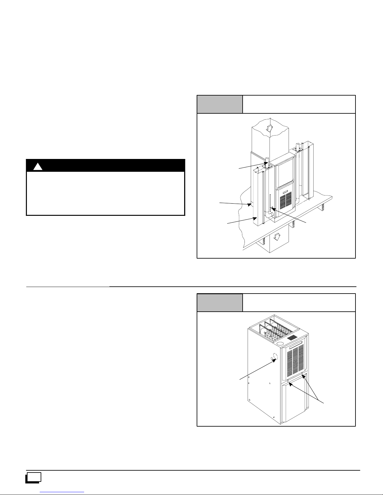
Figure 5
T y pical Downflow Installation
Downflow Venting: The combustion venter MUST be rotated to
ventoutthesideforalldownflowinstallations,(seeFigure 5). Bottomventingisnotpermitted.See“Sideventing”forinstructionsto
rotatethe venttothe side.Inadditiontorotatingtheventtotheside
a Vent Pipe Shield (NAHA002VC) is required to shield the hot
vent pipe.
!
WARNING
BURN HAZARD.
Vent pipe is HOT and could cause personal injury.
Hot vent pipe is in reach of small children when
installed in downflow position.
Install vent pipe shield NAHA002VC.
Pressure Switch Relocation
Ifthe furnaceisinstalledintheupflowposition, thepressureswitch
will remain in the same position as installed by the factory unless
the inducer is rotated. If the furnace is installed in an orientation
that places the pressure switch below the pressure tap on the inducerhousing,thentheswitchMUST be relocated. In order to re-
3. Side Venting
This furnace is shipped from the factory with the venter assembly
in an upflow configurations (top vent). The venter assembly can
easily be rotated to a side vent configurations for use in upflow,
horizontal--flow, or downflow application.
See side venting
for venter rotation
Combustible floor
base outlet flange
adapter
Vent Shield
Kit
Figure 6
RETURN
AIR
VENT
OPTIONAL VENT
SUPPLY
AIR
Furnace with Screws
GAS SUPPLY
MUST BE OPPOSITE
VENT DISCHARGE
SIDE
25--23--19
When using a side vent configuration (side outlet instead of top
outlet),it may be necessary to relocatethe pressure switch to the
alternatepositionontheoppositeside ofthetop panel. Twoscrew
holes are provided at the alternate position. Route the pressure
switch tubing so the tubing is not kinked and not touching the hot
collector box, venter housing, or motor. It may be necessary to
shorten the length of the tubing to properly route the tubing and
eliminate kinks.
Rotating the Venter Assembly
1. If gas and electrical power have already been connected to
unitshutoff gasandremovepower fromunit.Unscrewscrews
onburner compartmentdoorandremoveburnercompartment
door. See Figure 6.
2. Disconnectpowerleadstotheventermotorandhosetopressureswitch.Removethree (3) orfour(4)screws which secure
the venter to the collector box, (see Figure 7).
3. Cut webbing with a pair of snips holding the vent plate to the
cabinetoneither the leftorrightside ofunitdependingonright
or left venting as desired. Discard vent plate, (see Figure 6).
8
Vent Plate
Screws (2)
25--23--45
441 01 2611 06
Page 9
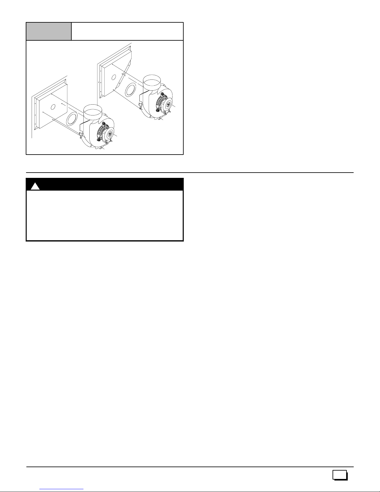
Figure 7
Venter Gasket
Entry
Main Line
25--23--52b
25--23--52c
4. Combustion & Ventilation Air
!
CARBON MONOXIDE POISONING HAZARD.
Failure to provide adequate combustion and
ventilationaircouldresultindeathand/orpersonal
injury.
Use methods described here to provide
combustion and ventilation air.
Furnaces require ventilation openings to provide sufficient air for
propercombustion and ventilation of flue gases. All duct or open ingsforsupplyingcombustionandventilationairmustcomplywith
thegascodes,orin the absenceoflocalcodes,the applicable national codes.
Combustion and ventilation air must be supplied in accordance
with one of the following:
1. Section8.3, AirforCombustionandVentilation,of theNational
Fuel Gas Code, (NFGC), ANSI Z223.1--2002/NFPA54--2002
in the U.S.,
2. Sections7.2,7.3,7.5, 7.6,7.7,and7.8 of NationalStandardof
Canada, Natural Gas and Propane Installation Code
(NSCNGPIC), CSA B149.1--00 in Canada,
3. Applicable provisions of the local building code.
When the installation is complete, check that all appliances have
adequate combustion air and are venting properly. See Venting
AndCombustionAirCheckin“5.GasVentInstallation” Section i n
this manual.
Contaminated Combustion Air
Installationsincertainareasortypes ofstructurescould causeexcessive exposure to contaminated air having chemicals or halogens that will result in safety and performance related problems
and may harm the furnace. These instances must use only outdoor air for combustion.
Thefollowingareasor types of structuresmaycontainorhave exposure to the substances listed below. The installation must be
441 01 2611 06
WARNING
4. Replace venter gasket (part # 1013540, if needed) to venter
assembly with adhesive in the same location as the old one.
5. Rotate venter assembly 90 ° right or left from original location
depending on venting configurations.
6. Tightenthe three (3) or four (4) screws that secure the venter
assembly to the collector box. Do tighten screws enough to
compress venter gasket.
7. Replace power leads to venter motor and reconnect hose to
pressure switch.
NOTE:Unused open vent hole must be covered. A VentCover is
suppliedwithVentPipeShieldKit NAHA002VC.A5
VentCoveri s availableseparatelyfromyourdistributor,or onecan
be fabricated with sheet metal for all side vent installations.
evaluated carefully as it may be necessary to provide outdoor air
for combustion.
5
/16² diameter
· Commercial buildings.
· Buildings with indoor pools.
· Furnaces installed in laundry rooms.
· Furnaces installed in hobby or craft rooms.
· Furnaces installed near chemical storage areas.
· Permanent wave solutions for hair.
· Chlorinated waxes and cleaners.
· Chlorine based swimming pool chemicals.
· Water softening chemicals.
· De--icing salts or chemicals.
· Carbon tetrachloride.
· Halogen type refrigerants.
· Cleaning solvents (such as perchloroethylene).
· Printing inks, paint removers, varnishes, etc.
· Hydrochloric acid.
· Sulfuric Acid.
· Solvent cements and glues.
· Antistatic fabric softeners for clothes dryers.
· Masonry acid washing materials.
Outdoor Combustion Air Method
Aspace havinglessthan50cubicfeetper1,000BTUHinputrating
forallgasappliancesinstalledin thespacerequiresoutdoorairfor
combustion and ventilation.
Air Openings and Connecting Ducts
1. Total input rating for all gas appliances in the space MUST be
considered when determining free area of openings.
2. Connect ducts or openings directly to the outdoors.
3. When screens are used to cover openings, the openings
MUST be no smaller than
4. The minimumdimensionof air ducts MUST NOT be less than
3² .
5. Whensizingagrille,louverorscreenusethefreeareaofopening. If free area is NOT stamped or marked on grill or louver,
assumea20%freeareafor woodand60%for metal. Screens
shall have a mesh size not smaller than
1
/4² mesh.
1
/4².
9
Page 10
Requirements
BTU
H
1. Providethespacewithsufficientairforpropercombustionand
ventilation of flue gases using horizontal or vertical ducts or
openings.
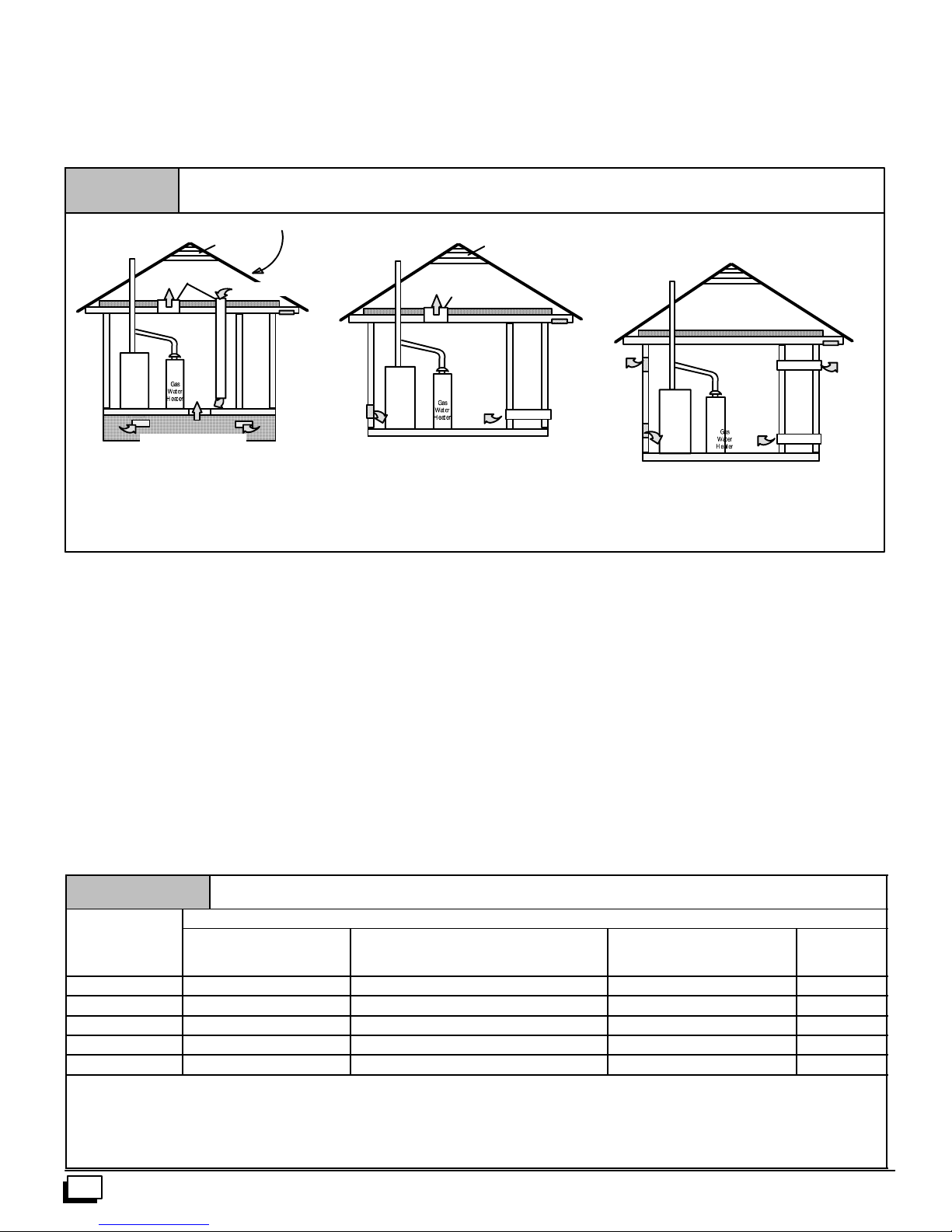
2. Figure 8illustrateshowtoprovidecombustionand ventilation
airwhentwopermanentopenings,oneinletandone outlet,are
used.
a. One opening MUST commencewithin12² of the floor
and the second opening MUST commence within 12² of
the ceiling.
b. Size openings and ducts per Table 1.
Figure 8
Outside Air (This is ONLY a guide. Subject to codes of country having jurisdiction.)
This installation NOT approved in Canada
Gas Vent
Minimum OneInlet and One Outlet AirSupply isRequired
Inlet Air OpeningMust be Within12²(300mm) of floor
Outlet Air OpeningMust be Within12²(300mm) of ceiling
(1) 1 Square Inch(6cm
(2) 1 Square Inch(6cm
VentilatedAttic
TopAbove Insulation
Outlet Air (1)
Furnace
VentilatedCrawl Space
May bein and Combination Shown
2
2
c. Horizontal duct openings require 1 square inch of free
areaper2,000BTUH(1,100mm2/kW)ofcombinedinput
for all gas appliances in the space (see Table 1).
d. Verticalduct openings oropeningsdirectlycommunicat-
ing with the outdoors require 1 square inch of free area
per4,000 BTUH (550 mm
gas appliances in the space (see Table 1).
3. When one permanent outdoor opening is used, the opening
requires:
a. 1 sq. in of free area per 3,000 BTUH (700 mm
combined input of all gas appliances in the space (see
Table 1) and
Gable Ve nt
Inlet
Air (1)
) per 4000BTUH
) per 2000BTUH
Optional InletAir (1)
Soffit Vent
2
/kW)for combined input of all
b. notlessthanthesumoftheareasofallventconnectorsin
the space.
The opening shall commence within 12² of the top of the enclosure.Appliancesshallhaveclearancesofatleast1² fromthesides
andbackand6² from the front.Theopeningshalldirectly commu-
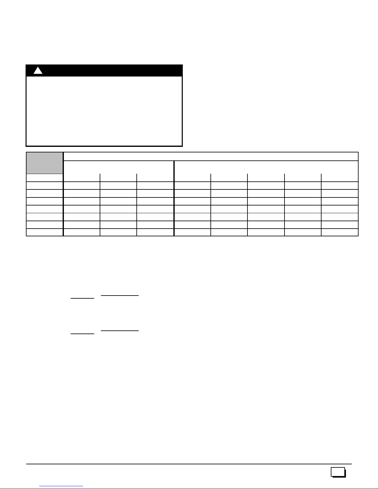
Table 1
Input
Rating
50,000 25 sq. in. 16.7 sq. in. 12.5 sq. in. 4²
75,000 37.5 sq. in. 25 sq. in. 18.75 sq. in. 5²
100,000 50 sq. in. 33.3sq.in. 25 sq. in. 6²
125,000 62.50 sq. in. 41.7 sq. in. 31.25 sq. in. 7²
150,000 75 sq. in. 50 sq. in. 37.5 sq. in. 7²
EXAMPLE: Determining Free Area
Furnace
100,000
Furnace
100,000
Free Area
TwoHorizontal Ducts
(sq. in./2,000 BTUH)
Water Heater
+
+
30,000
Water Heater
30,000
10
Gable Ve nt
Soffit Vent
Inlet
Air (2)
Outlet
Air (1)
Inlet
Air (1)
Inlet
Air (1)
Gas Vent
VentilatedAttic
TopAbove Insulation
Outlet Air (1)
Furnace
nicatewiththeoutdoorsorshallcommunicatethroughaverticalor
horizontalductto the outdoorsorspaces(crawlor attic)thatfreely
communicate with the outdoors.
4. Combination of Indoor and Outdoor Air shall have:
a. Indoor openings that comply with the Indoor Combus-
tion Air Method below and
b. Outdoor openings located as required in the Outdoor
Combustion Air Method above and
2
/kW) for
c. Outdoor openings sized as follows.
1) Calculate the Ratio of all Indoor Space volume dividedby requiredvolumeforIndoorCombustionAirMethod. Outdoor openings sized as follows.
2) Outdooropeningsizereduction Factor is1 minusthe
Ratio in 1) above.
3) Minimum size of Outdoor openings shall be the size
required in Outdoor Combustion Air Method above
multiplied by reduction Factor.
Minimum FreeAreaRequiredfor Each Opening or Duct to Outdoors
Single Opening
(sq. in./3,000 BTUH)
Total Input
=
(130,000 ¸ 4,000)
Total Input
=
(130,000 ¸ 2,000)
==32.5 Sq. In. Vertical
65 Sq. In. Horizontal
Gas Vent
Furnace
TwoVertical Ducts or Openings
(sq. in./4,000BTUH)
Outlet
Air (2)
Inlet
Air (2)
Round Duct
(sq. in./4,000
BTUH)
441 01 2611 06
Page 11
Indoor Combustion Air
Standard and Known--Air--Infiltration Rate Methods
ã NFPA&AGA
Indoor air is permitted for combustion and ventilation, if the
Standard or Known--Air--Infiltration Rate Method is used.
!
CARBON MONOXIDE POISONING HAZARD.
Failure to supply adequate combustion air could
result in death and/or personal injury.
Mosthomeswillrequireadditionalairfrom outdoors
for combustion and ventilation. A space with atleast
WARNING
The Standard Method may be used, if the space has no less volumethan50cubicfeetper1,000BTUHof the maximum input ratings for all gas appliances installed in the space. The standard
method permits indoor air to be used for combustion and ventilation air.
The Known Air Infiltration Rate Method shall be used if the infiltration rate is known to be less than 0.40 air c hanges per hour
(ACH) and equal to or greater than 0.10 ACH. Infiltration rates
greater than 0.60 ACH shall not be used. The minimum required
volume of the space varies with the number of ACH and shall be
determined per Table 2 or Equations 1 and 2. Determine the
minimum required volume for each appliance in the space, and
add the volumes together to get the total minimum required volume for the space.
50 cubic feet per 1,000 BTUH input rating or homes
with tight construction may need outdoor air to
supplement air infiltration for proper combustion
and ventilation of flue gases.
MINIMUM SPACE VOLUME FOR 100% COMBUSTION AND VENTILATION AIR FROM INDOORS (ft3)
Table 2
ACH
0.60 1,050 1,400 1,750 1,250 1,875 2,500 3,125 3,750
0.50 1,260 1,680 2,100 1,500 2,250 3,000 3,750 4,500
0.40 1,575 2,100 2,625 1,875 2,813 3,750 4,688 5,625
0.30 2,100 2,800 3,500 2,500 3,750 5,000 6,250 7,500
0.20 3,150 4,200 5,250 3,750 5,625 7,500 9,375 11,250
0.10 6,300 8,400 10,500 7,500 11,250 15,000 18,750 22,500
0.00 NP NP NP NP NP NP NP NP
Other Than Fan-Assisted Total
(1,000’sBtuh)
30 40 50 50 75 100 125 150
Fan-assistedTotal
(1,000’sBtuh)
NP = Not Permitted
Table 2MinimumSpaceVolumesweredetermined by usingthe
following equations from the National Fuel Gas Code ANSI
Z223.1/NFPA 54--2002, 8.3.3.2:
1. For other than fan--assisted appliances such as a draft
hood--equipped water heater,
(
1000 Btu / hr
(
1000 Btu / hr
I
I
other
fan
)
)
3
Volume
other
2. For fan--assisted appliances such as this furnace,
Volume
If:
I
I
ACH = air changes per hour (ACH shall not exceed 0.60.)
The following requirements apply to the Standard Method and to
the Known Air Infiltration Rate Method.
=
fan
= combined input of all other than fan--assisted
other
appliances in Btu/hr
=combinedinputofallfan--assisted appliancesinBtu/hr
fan
21 ft
=
ACH
3
15 ft
ACH
· Adjoining rooms can be considered part of a space, if there
are no closable doors between rooms.
· An attic orcrawlspacemaybeconsidered a space thatfreely
communicateswiththeoutdoorsprovidedthereareadequate
ventilationopeningsdirectly tooutdoors.Openings MUST remainopenandNOThaveanymeansofbeingclosed off.Ven-
tilation openings to outdoors MUST be at least 1 square inch
offreeareaper4,000BTUH of totalinputratingforall gas appliances in the space.
· In spaces that use the Indoor Combustion Air Method, in-
filtration should be adequate to provide air for combustion,
ventilation and dilution of flue gases. However, in buildings
withunusuallytightconstruction,additional air MUST beprovided using the methods described in section titled Outdoor
Combustion Air Method:
· Unusually tight construction is defined as Construction with:
1. Wallsand ceilings exposed to the outdoors have a continuous,sealed vapor barrier.Openingsaregasketed or
sealed and
2. Doors and openable windows are weather stripped and
3. Other openings are caulked or sealed. These include
joints around window and door frames, between sole
plates and floors, between wall--ceiling joints, between
wall panels, at penetrations for plumbing, electrical and
gas lines, etc.
Ventilation Air
Someprovincialcodesandlocal municipalities requireventilation
ormake--up airbe brought into the conditioned space asreplacementair.Whichevermethodisused,the mixedreturnairtemperature across the heat exchanger MUST not fall below 60°
continuously,or55° onanintermittentbasis so that flue gases will
not condense excessively in the heat exchanger.Excessive condensation will shorten the life of the heat exchanger and possibly
void your warranty.
441 01 2611 06
11
Page 12

5. Gas Vent Installation
!
CARBON MONOXIDE POISONING, FIRE AND
EXPLOSION HAZARD.
Failure to properly vent this furnace could result in
death, personal injury and/or property d amage.
Read and follow all instructions in this section.
Install the vent in compliance with codes of the country having jurisdiction, local codes or ordinances and these instructions.
This Category I furnace is fan--assisted. Afan assisted appliance
isanapplianceequipped withanintegralmechanicalmeans toeither draw or force products of combustion through the heat exchanger.
Category I furnace definition: A central furnace which operates
with a non--positive vent static pressure and with a flue loss not
lessthan17percent. These furnaces are approved forcommon-venting and multi--story venting with other fan--assisted or draft
hood--equipped appliances in accordance with the NFGC or
NSCNGPIC
Category I Safe Venting Requirements
Category I furnace vent installations shall be in accordance with
Parts 10 and 13 of the National Fuel Gas Code (NFGC), ANSI
Z223.1--2002/NFPA54 --2002;and/orSection7andAppendixCof
the CSA B149.1--00, National Standard of Canada, Natural Gas
and Propane Installation Code; the local building codes; furnace
and vent manufacturer’s instructions.
NOTE: The following instructions comply with the ANSI
Z223.1/NFPA54 National Fuel Gas Code and CSA B149.1Natural Gas and Propane Installation code, based on the input rate on
the furnace rating plate.
1. If a Category I vent passes through an attic, any concealed
space or floor, use ONLY Type B or Type L double wall vent
pipe.Ifventpipepasses through interior wall, useTypeB vent
pipe with ventilated thimble ONLY.
2. Do NOT vent furnace into any chimney serving an open fireplace or solid fuel burning appliance.
3. Use the same diameter Category I connector or pipe as permitted by:
· the National Fuel Gas Code Code (NFGC) ANSI
· the NationalStandard of Canada Natural Gas and Pro-
4. Push the vent connector onto the furnace flue collar of the
venterassemblyuntilittouchesthebead(atleast
and fasten with at least two field--supplied, corrosion--resistant, sheet metal screws located at least 140° apart.
5. Keep vertical Category I vent pipe or vent connector runs as
short and direct as possible.
6. Verticaloutdoor runs of Type--B or ANY single wall vent pipe
below the roof line are NOT permitted.
7. Slopeallhorizontalruns upfromfurnace totheventterminal a
minimum of
WARNING
Z223.1--2002 / NFPA54--2002 sections 10 and 13 venting requirements in the United States
or
pane Installation Code (NSCNGPIC) CSA B149.1--00
section7andappendixCventing requirements inCanada.
5
/8² overlap)
1
/4² per foot (21 mm/m).
8. Rigidlysupportallhorizontalportionsoftheventingsystemevery6¢ orlessusingproperclampsandmetalstrapsto prevent
sagging and ensure there is no movement after installation.
9. Checkexistinggas ventorchimneyto ensuretheymeetclearances and local codes. See Figure 1
10. The furnace MUST be connected to a factorybuilt chimney or
vent complying with a recognized standard, or a masonry or
concretechimneylined withaliningmaterialacceptable tothe
authority having jurisdiction. Venting into an unlined ma-
sonrychimneyor concretechimneyis prohibited.Seethe
6. Masonry Chimney Venting section in these instructions.
11. Fan--assisted combustion system Category I furnaces shall
not be vented into single--wall metal vents.
12. Category I furnaces must be vented vertically or nearly vertically, unless equipped with a listed mechanical venter.
13. VentconnectorsservingCategoryIfurnaces shallnotbeconnectedintoanyportionofmechanical draft systems operating
under positive pressure.
A4--to-- 3 inchreducerispermitted attheflue collarwheninstalling
a50,000Btuhgasinputfurnace, iftheinstallationmeets allthefollowing requirements for sizing the vent connectors and vents:
1. The National Fuel Gas Code, ANSI
Z223.1/NFPA--54--2002, sections 10.5.3.1(1),
10.6.3.1(2), 10.10.3.1, 13.1.2, 13.1.10, and 13.2.21(1)
through (3) in the U.S. or
2. The Natural Gas and Propane Installation Code CSA
B149.1--00, sections 7.13.1(b), 7.13.2(b), 7.18.5(b),
and Appendix C--GVR no. 2. in Canada.
12
441 01 2611 06
Page 13
Venting and Combustion Air Check
NOTE: When an existing Category I furnace is removed or replaced,theoriginalventingsystemmaynolongerbesizedtoprop erly vent the attached appliances, and to make sure there is
adequate combustion air for all appliances, MAKE THE FOL-
LOWING CHECK.
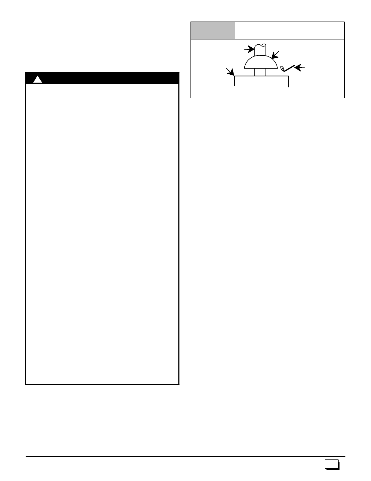
Figure 9
Typical Gas
Water Heater
Vent Check
Draft HoodVent Pipe
Match
!
CARBON MONOXIDE POISONING HAZARD
Failure to follow the steps outlined below for each
applianceconnectedtothe venting systembeingplaced
into operation, could result in carbon monoxide
poisoning or death:
The followingsteps shall be followed for each appliance
connected to the venting system being placed into
operation, while all other appliances connected to the
venting system are not in operation:
1.Seal any unused openings in the venting system.
2.Inspect the venting system for proper size and horizontal
pitch, as required in the National Fuel Gas Code, ANSI
Z223.1/NFPA 54 or CSA B149.1, Natural Gas and
Propane Installation Code and these instructions. Deter -
minethatthereisnoblockageorrestriction,leakage,corrosionandotherdeficiencieswhichcouldcauseanunsafe
condition.
3.As far as practical, close all building doors and windows
andalldoors between thespaceinwhich theappliance(s)
connected to the venting system are located and other
spaces of the building.
4.Close fireplace dampers.
5.Turnonclothesdryersandanyappliancenotconnectedto
the venting system. Turn on any exhaust fans, such as
range hoods and bathroom exhausts, so they are
operating at maximum speed. Do not operate a summer
exhaust fan.
6.Followthelightinginstructions.Place the appliance being
inspected into operation. Adjust the thermostat so
appliance is operating continuously.
7.Test for spillage from draft hood equipped appliances at
thedraft hoodreliefopeningafter5minutesof mainburner
operation.Use the flame of a matchor candle. (Figure 9)
8.If improper venting is observed, during any of the above
tests,the ventingsystemmustbecorrectedinaccordance
with the National Fuel Gas Code, ANSI Z223.1/NFPA 54
and/orCSAB149.1,NaturalGasand PropaneInstallation
Code.
9.After it has been determined that each appliance con nected to the venting system properly vents when tested
as outlined above, return doors, windows, exhaust fans,
fireplace dampers and any other gas--fired burning
appliance to their previous conditions of use.
WARNING
NOTE: If flame pulls towards draft hood, this indicates
sufficient infiltration air.
Venting to Existing Masonry Chimney
Dedicated venting of one fan assisted furnace into any masonry chimney is restricted. A chimney must first be lined with
either Type B vent sized in accordance with NFGC tables 13.1 or
13.2 or a listed, metal lining system, or venting into a masonry
chimneyispermittedasoutlinedwith use of an optional listed masonry chimney kit. (See Section 7 Masonry Chimney Venting of
these instructions.)
Listed, corrugated metallic chimney liner systems in masonry
chimneysshallbesizedbyusing NFGC tables per13.1.7fordedicated venting and per 13.2.19 for common venting with the maximum capacity reduced by 20% (0.80 X maximum capacity) and
theminimumcapacityasshownintheapplicabletable.InCanada,
use the NSCNGPIC, appendix C, section 10. Corrugated metal
vent systems installed with bends or offsets require additional reductionof 5%oftheventcapacityforeach bendupto45° and10%
of the vent capacity for each bend from 45° up to 90°.
NOTE:Two(2)45° elbows are equivalent to one (1) 90° elbow.
Combined Venting into a Masonry Chimney
Ventingintoamasonryorconcretechimneyisonlypermitted
as outlined in the NFGC or NSCNGPIC venting tables. Follow
all safe venting requirements.
Note: See section “7. Masonry Chimney Venting”.
441 01 2611 06
13
Page 14

6. Horizontal Venting
Category I Furnaces With External Power
Venters
InordertomaintainaCategory Iclassificationof fan--assistedfurnaceswhenventedhorizontallywithsidewalltermination,apower
venter is REQUIRED to maintain a negative pressure in the venting system.
In the U.S.: Per the NFGC, a listed power venter may be used,
when approved by the authority having jurisdiction.
In Canada: Only power venters approved by the appliance
manufacturer and where allowed by the authority having jurisdiction may be used
PleaseconsulttheFieldsControlsCo. or Tjernlund Products, Inc.
for power venters certified for use with our furnaces.
Vent Termination
VentingThrough a Non--Combustible and
Combustible Wall
Consult External Power Venter manufacturer instructions.
SelectthepowerventertomatchtheBtuhinputofthefurnacebeingvented. Followallof thePowerVenter manufacturer’s installation requirements included with the power venter for:
· venting installation,
· vent terminal location,
· preventing blockage by snow,
· protecting building materials from degradation by flue gases,
· see Figure 1 0 for required vent termination.
NOTE: It is the responsibility of the installer to properly terminate
theventandprovideadequateshielding. This is essential inorder
to avoid water/ice damage to building, shrubs and walkways.
14
441 01 2611 06
Page 15

Figure 10
Other than Direct Vent Termination Clearance
N
V
V
D
E
V
B
V
C
F
B
V
VENT TERMINAL
Item Clearance Descriptions Canadian Installation(1)
A Clearance above grade, veranda, porch,deck,balcony,or
anticipated snow level
B Clearance to awindowor door that may be opened 6² (15 cm) forappliances £ 10,000 BTUH (3kW), 12² (30
C Clearance toapermanently closed window
D Verticalclearance toa ventilated soffitlocatedabovethe ter-
minal within a horizontal distance of 2¢ (61cm) from thecenterline of theterminal
E Clearance to anunventilated soffit
F Clearance to anoutsidecorner
G Clearancetoan inside corner
H Clearance toeachside ofthecenterline extended above elec-
trical meter or gas service regulator assembly
I Clearance to service regulator vent outlet 3¢ (91cm)
J Clearance tonon--mechanical air supply inlet to building or the
combustion air inlet to anyotherappliance
K Clearance to amechanical air supply inlet 6¢ (1.83 m) 3¢ (91cm)aboveif within 10¢ (3mhorizontally)
L Clearance under a veranda, porch, deck, orbalcony 12² (30 cm) +
M Clearanceto eachsideofthe centerline extended above or
below vent terminal of thefurnace toadryer or water heater
vent, or otherappliance’s direct vent intake or exhaust.
N Clearance from aplumbingventstack 3¢ (91cm) 3¢ (91cm)
(1.) In accordance with the current CSAB149.1,Natural Gas andPropane Installation Code
(2.) In accordance with the currentANSIZ223.1/NFPA54, National Fuel Gas Code
#18² (46cm)aboveroof surface
+ Permitted only if veranda, porch, deck, or balcony is fully open ona minimum of twosides beneath thefloor.
B
V
B
B
X
AIR SUPPLYINLET
12² (30cm) # 12² (30cm)
cm) for appliances > 10,000Btuh(3 kW) and£ 100,000 Btuh
(30kW),36² (91 cm) for appliances > 100,000Btuh(30 kW)
* *
* *
* *
* *
* *
3¢ (91cm) within15¢ (4.5 m) above the meter/regulator
assembly
6² (15 cm) forappliances £ 10,000 BTUH (3kW), 12² (30
cm) for appliances > 10,000Btuh(3 kW) and £ 100,000 Btuh
(30kW),36² (91 cm) for appliances > 100,000 Btuh (30kW)
* *
B
X
J
A
H
I
L
K
AREA WHERE TERMINAL ISNOTPERMITED
G
X
V
4¢ (1.2m) below ortothe side of the opening. 1¢ (30 cm)
above theopening.
3¢ (91cm) within15¢ (4.5 m)abovethe meter/regulator
assembly
*
4¢ (1.2m) below ortothe side of opening: 1¢ (30cm) above
opening.
*
M
A
V
25--24--65--2
U.S. Installation (2)
* For clearances not specified in ANSI Z223.1/NFPA 54orCSA B149.1, clearances shall be inaccordancewithlocalinstallation codes andtherequirements of thegassupplier and themanufacture’s
installation instructions.
Notes:
1. The ventforthis appliance shall not terminate
a. Over public walkways; or
b. Near soffit vents orcrawlspacevents or otherareaswhere condensate orvapor could create anusiance or hazard orpropertydamage; or
c. Where condensate vapor could cause damage or could bedetrimental to theoperationof regulators, relief valves, or other equipment.
2. When locatingvent terminations,considerationmust begivento prevailingwinds,location, andother conditions which may causerecirculation of thecombustiob products of adjacent vents.
Recirculation can cause poor combustion, inlet condensate problems, and accelerated corrosion of the heatexchangers.
441 01 2611 06
15
Page 16
7. Masonry Chimney Venting
Chimney Inspection
All masonry chimney construction must conform to Standard
ANSI/NFPA211--2003 and to any state or local codes applicable.
The chimney must be in good condition and a complete chimney
inspectionmustbeconductedpriortofurnace installation.Iftheinspection reveals damage or abnormal conditions, make necessary repairs or seek expert help. See Figure 11 “The Chimney
Inspection Chart”. Measure inside area of tile --liner and exact
height of chimney from the top of the c himney to the highest appliance flue collar or drafthood outlet.
Connector Type
To reduce flue gas heat loss and the c hance of condensate problems, the vent connector must be double--wall Type B vent.
VentingRestrictions for Chimney Types
Interior Chimney -- has no sides exposed to the outdoors below
the roofline. All installations can be single furnace or common
vented with another draft hood equipped Category I appliance.
Exterior Chimney -- has one or more sides exposed to the outdoors below the roof line. All installations with a 99% Winter Design Temperature*below17°F must be common vented only with
a draft hood equipped Category I appliance.
The 99% Winter Design Dry--Bulb (db) temperatures are found in the
*
1993 ASHRAE Fundamentals Handbook, Chapter 24, Table 1 (United
States)and2(Canada),orusethe99.6% heatingdb temperaturesfound
in the 1997 or 2001 ASHRAE Fundamentals Handbook, Climatic
Design Information chapter, Table 1A (United States) and 2A
(Canada).
!
CARBON MONOXIDE POISONING, FIRE AND
EXPLOSION HAZARD.
Failure to properly vent this furnace could result in
death, personal injury and/or property d amage.
These furnaces are CSA (formerly AGA and CGA)
design--certified for venting into exterior clay
tile--lined masonry chimneys with a factory
accessory Chimney Adapter Kit. Refer to the
furnace rating plate for correct kit usage. The
Chimney Adapter Kits are for use with ONLY
furnaces having a Chimney Adapter Kit number
marked on the furnace rating plate.
WARNING
Ifa claytile--linedmasonrychimneyisbeingusedanditisexposed
to the outdoors below the roof line, relining might be required.
Chimneys shall conform to the Standard for Chimneys, Fireplaces, Vents, and Solid Fuel Burning Appliances ANSI/NFPA
211--2003 in the United States and to a Provincial or Territorial
Building Code in Canada (in its absence, the National Building
Code of Canada) and must be in good condition.
U.S.A.--Refer toSections13.1.9or13.2.20ofthe NFGCortheauthorityhavingjurisdictiontodeterminewhetherreliningisrequired.
If relining is required, use a properly sized listed metal liner,
Type--B vent, or a listed alternative v enting design.
NOTE: See the NFGC, 13.1.9 and 13.2.20 regarding alternative
venting design and the exception, which cover installations such
as the Chimney Adapter Kits NAHA001DH and NAHA002DH.
The Chimney Adapter Kits are listed alternative v enting designs
for these furnaces. See the kit instructions for complete details.
Canada(and U.S.A.)--Thisfurnaceispermittedtobeventedintoa
clay tile--lined masonry chimney that is exposed to the outdoors
below the roof line, provided:
1. Ventconnector is Type--B double--wall, and
2. This furnace is common vented with at least 1 draft hood-equipped appliance, and
3. The combined appliance input rating is less than the maximum capacity given in Table A, and
4. Theinputratingofeachspace--heatingapplianceisgreater
than the minimum input rating given in Table B for Masonry
Chimneys for the local 99% Winter Design Temperature.
Chimneys having internal areas greater than 38 square
inches require furnace input ratings greater than the input
ratingsofthesefurnaces. SeefootnoteatbottomofTableB,
and
5. The authority having jurisdiction approves.
Ifall of these conditions cannot be met, an alternative venting design shall be used, such as the listed chimney adapter kit with a
furnace listed for use with the kit, a listed chimney--lining system,
or a Type--B vent.
These furnaces are CSA design--certified for use in exterior clay
tile--lined masonry chimneys with a factory accessory Chimney
AdapterKit. Refer to the furnace ratingplateforcorrectkitusage.
The Chimney Adapter Kits are listed alternative v enting designs
andarefor use withONLY furnaces having aChimneyAdapterKit
number marked on the furnace rating plate.
16
441 01 2611 06
Page 17
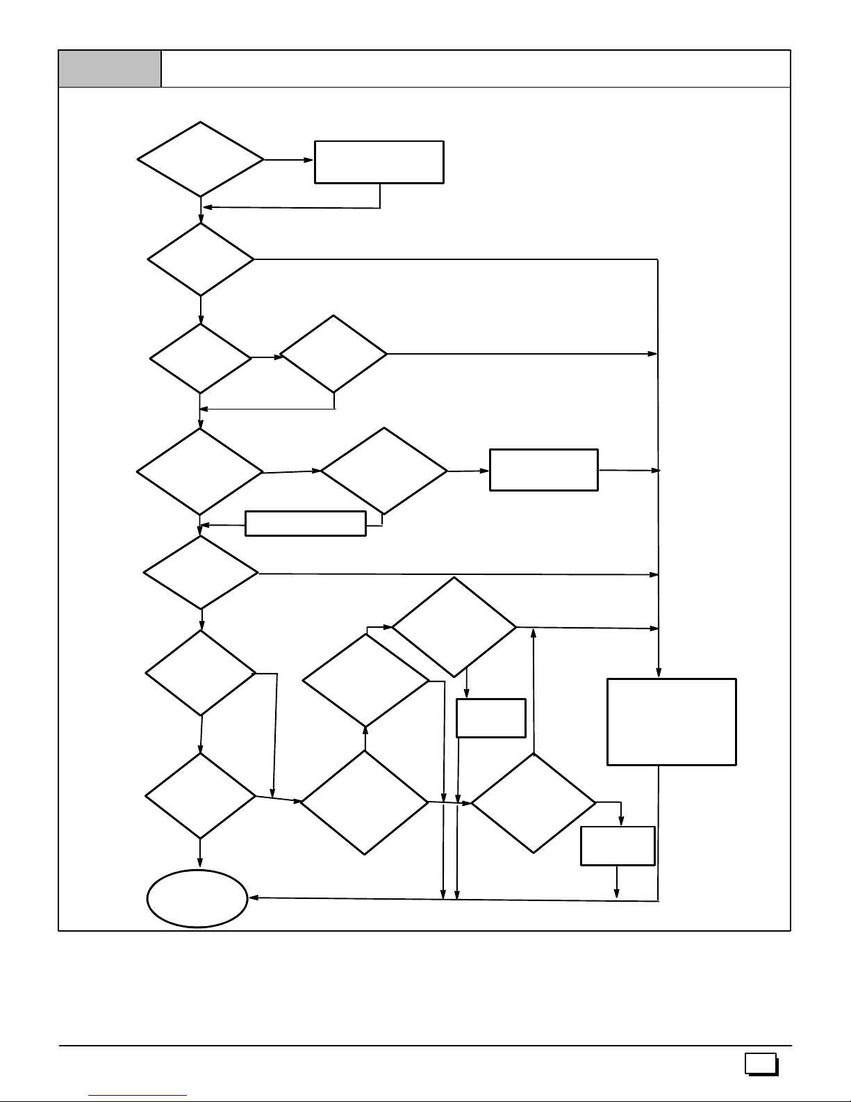
Figure 11
CHIMNEY INSPECTION CHART
ForadditionalrequirementsrefertotheNationalFuelGasCodeNFPA54/ANSIZ223.1--2002andANSI/NFPA211--2003Chimneys,Fireplaces, Vents,andSolidFuel
BurningAppliancesin the U.S.A. or to the Canadian InstallationCodeCSAB149.1--00 in Canada.
Crown
condition:
Missingmortar
or brick?
No
Is
Chimney properly lined
with clay tile
liner?
Yes
Is
liner and top
seal in good
condition
Yes
Debris in
cleanout? Mortar,tile,
metal vent, fuel oil
residue?
No
Yes
No
Repair
No
liner or topseal
or reline chimney as
necessary.
Yes
Remove metal vent orliner.
Repair
Rebuild
crown
Mortar or
tile debris?
Reline
No
Yes
Remove mortar
and tile debris?
Clay
tile misalignment,
missingsections,
gaps?
No
Condensate
drainage at bottom
of chimney?
No
Chimney
exposed to outdoors
below roof line?
No
Chimneyis
acceptable for use
Yes
Yes
Yes
No
Is Chimney
lined with properly
sized, listed liner or
Type--B vent?
Yes
Is Chimney to
be dedicated toa
single furnace?
Consult
Part B ofchimney
adapter venting
instructionsfor
application
suitability.
Suitable
Yes
Install chimney
adapter per
instructions.
No
Not Suitable
Not Suitable
Consult
Part C ofchimney
adapter venting
instructionsfor
application
suitability.
Line chimney with properly
sized, listed flexible metal
liner or Type--B vent per NFGC or
NSCNGPIC VentSizing Tables
and liner orventmanufacturer’s
installation instructions.
Suitable
Install chimney
adapter per
instructions.
441 01 2611 06
17
Page 18
Exterior Masonry Chimney,
G
6
o
7
o
5
4
t
1
o
r
FAN+NAT Installations with
Type--B Double--Wall Vent Connectors
ã
ã NFPA&AGA
ãã
Table A--
Combined Appliance
Maximum Input Rating in
Thousands of Btu per Hr
VENT
HEIGHT
(FT)
6 74 119 178 257
8 80 130 193 279
10 84 138 207 299
15 NR 152 233 334
20 NR NR 250 368
30 NR NR NR 404
INTERNAL AREA OF CHIMNEY
(SQ IN.)
12 19 28 38
Table B--
Minimum Allowable Input Rating of
Space--Heating Appliance in
Thousands of Btu per Hr
VENT
HEIGHT
(FT)
Local 99% Winter Design Temperature: 17 to 26°°°° F*
6 0 55 99 141
°
°F
°
°
8 52 74 111 154
6
10 NR 90 125 169
o2
15 NR NR 167 212
7t
1
20 NR NR 212 258
30 NR NR NR 362
Local 99% Winter Design Temperature: 5 to 16°°°° F*
6 NR 78 121 166
8 NR 94 135 182
°
°F
°
°
16
10 NR 111 149 198
15 NR NR 193 247
5t
20 NR NR NR 293
30 NR NR NR 377
Local 99% Winter Design Temperature: --10 to 4°°°° F*
6 NR NR 145 196
°
°F
°
°
8 NR NR 159 213
4
10 NR NR 175 231
to
15 NR NR NR 283
10
--
20 NR NR NR 333
30 NR NR NR NR
-- 1 1 °°°° F
lower
Local 99% Winter Design Temperature: --11°°°° For
or
INTERNAL AREA OF CHIMNEY
(SQ IN.)
12 19 28 38
lower*
Not recommended for any vent configuration
* The 99% Winter Design Dry--Bulb (db) temperatures are found in the
1993 ASHRAE Fundamentals Handbook, Chapter 24, Table 1
(United States) and 2 (Canada), or use the 99.6% heating db
temperaturesfound in the 1997 or 2001 ASHRAE Fundamentals
Handbook, Climatic Design Information chapter, Table 1A (United
States) and 2A (Canada).
Inspectionsbeforethesaleandatthetimeofinstallationwilldeterminetheacceptabilityofthechimney or the need for repair and/or
(re)lining. Refer to the Chimney Inspection Chart to perform a
chimney inspection.
18
If the inspection of a previously used tile--lined chimney:
a. Showssignsof ventgascondensation,thechimneyshould
be relined in accordance with local codes and the authority
having jurisdiction. The chimney should be relined with a
listed metal liner, Type--B vent, or a listed chimney adapter
kittoreducecondensation. Ifacondensatedrainisrequired
bylocalcode,refer totheNFGC,Section 10.9foradditional
information on condensate drains.
b. Indicates the chimney exceeds the maximum permissible
sizeinthe tables, thechimneyshould berebuiltorrelined to
conform to the requirements of the equipment being
installed and the authority having jurisdiction.
Achimneywithoutaclaytileliner,which is otherwise in good condition,shallberebuilttoconformtoANSI/NFPA211orbelinedwith
a UL listed (ULC listed in Canada) metallinerorULlistedType--B
vent. Relining with a listed metal liner or Type--B vent is considered to be a vent--in-- a--chase.
If a metal liner or Type--B vent is used to line a chimney,no other
appliance shall be vented into the annular space between the
chimney and the metal liner.
APPLIANCE APPLICATION REQUIREMENTS
Appliance operation has a significant impact on the performance
of the venting system. If the appliances are sized, installed, adjusted, and operated properly, the venting system and/or the appliances should not suffer from condensation and corrosion. The
ventingsystemandallappliancesshall beinstalledinaccordance
with applicable listings, standards, and codes.
The furnace should be sized to provide 100 percent of the design
heating load requirement plus any margin that occurs because of
furnace model size capacity increments. Heating load estimates
can be made using approved methods available from Air Conditioning Contractors of America (Manual J); American Society of
Heating, Refrigerating, and Air--Conditioning Engineers; or other
approved engineering methods. Excessive oversizing of the furnace could cause the furnace and/or vent to fail prematurely.
Whena metalventormetallinerisused,thevent orlinermustbein
goodcondition andbeinstalled inaccordancewiththevent orliner
manufacturer’s instructions.
To prevent condensation in the furnace and vent system, the following precautions must be observed:
1. Thereturn--airtemperaturemustbe at least60°Fdbexcept
forbriefperiodsoftimeduringwarm--up from setback atno
lower than 55°F db or during initial start--up from a standby
condition.
2. Adjust the gas input rate per the installation instructions.
Lowgas inputrate causeslowventgastemperatures,causing condensation and corrosion in the furnace and/orventing system. Derating is permitted only for altitudes above
2000¢.
3. Adjust the air temperature rise to the midpoint of the rise
rangeorslightly above. Lowairtemperaturerisecancause
low vent gas temperature and potential for condensation
problems.
4. Set the thermostat heat anticipator or cycle rate to reduce
short cycling.
Air for combustion must not be contaminated by halogen compoundswhichincludechlorides,fluorides, bromides, andiodides.
These compounds are found in many common home products
suchas detergent,paint,glue,aerosolspray,bleach,cleaningsolvent,salt, and air freshener, and can cause corrosion of furnaces
and vents. Avoidusing such products in the combustion--air supply. Furnace use during construction of the building could cause
thefurnace tobe exposedtohalogencompounds,causingpremature failure of the furnace or venting system due to corrosion.
441 01 2611 06
Page 19

Vent dampers on any appliance connected to the common vent
GasT
cancausecondensationandcorrosion in the venting system. Do
notuseventdamperson appliances common ventedwiththisfurnace.
8. Gas Supply and Piping
!
WARNING
CARBON MONOXIDE POISONING, FIRE AND
EXPLOSION HAZARD.
Failure to follow safety warnings exactly could
result in serious injury, death, and/or property
damage.
Models designated for Natural Gas are to be used
withNaturalGasONLY,unlessproperlyconvertedto
use with LP gas.
Gas Supply Requirements
· UseonlytheTypeofgas approvedforthis furnace.Seerating
plate for approved gas type.
· Gasinputmustnotexceedthe ratedinputshownonthe rating
plate. Overfiring will result in failure of heat exchanger and
cause dangerous operation.
· Donotallowminimumsupplypressuretovarydownward. Do-
ingso will decrease input to furnace. Refer to Table 3 for gas
supply. Refer to Table 7 and Table 8 for manifold pressures.
Table 3 Gas Pressures
!
WARNING
FIRE HAZARD
Failure to follow safety warnings exactly could
result in serious injury, death, and/or property
damage.
Use wrench to hold furnace gas control valve when
turning elbows and gas line to prevent damage to
the gas control valve and furnace.
Figure 12
Typical Gas Piping (N8MP)
Manual Equipment Shutoff Valve
Left entry
Union
ype
Natural 7² 14² 4.5²
Propane 11² 14² 11²
Recommended Max. Min.
Supply Pressure
Gas Piping Requirements
NOTE:Thegassupplylinemustbeinstalledbya qualifiedservice
technician in accordance with all building codes.
NOTE: In the state of Massachusetts.
a. Gas supply connections MUST be performed by a li-
censed plumber or gas fitter).
b. Whenflexibleconnectorsare used, the maximumlength
shall not exceed 36² (915 mm).
c. When lever handle type manual equipment shutoff
valves are used, they shall be T--handle valves.
d. TheuseofcoppertubingforgaspipingisNOTapproved.
1. Installgaspipingin accordance with local codes,orintheabsence of local codes, the applicable national codes.
2. Itisrecommendedthat a manual equipment shutoff valve be
installed in the gas supply line outside the furnace. Locate
valveasclosetothefurnaceaspossiblewhereitis readilyaccessible. Refer to Figure 12.
441 01 2611 06
Right entry
Dipleg&pipecap
Left side entry
3. Useblack ironorsteel pipeandfittings orotherpipeapproved
by local code.
4. Use pipe thread compound which is resistant to natural and
LP gases.
5. Use ground joint unions and install a drip leg no less than 3²
long to trap dirt and moisture before it can enter gas control
valve inside furnace.
6. Providea
immediately up stream of gas supply connection to furnace.
7. Usetwopipewrencheswhenmakingconnectionstoprevent
furnace gas control valve from turning.
NOTE:Iflocalcodes allow the use ofaflexiblegasappliance connector,alwaysusea newlistedconnector. Donotusea connector
which has previously served another gas appliance.
8. Flexible corrugated metal gas connector may NOT be used
inside the furnace or be secured or supported by the furnace
or ductwork.
9. Properlysizegas pipe to handle combined appliance load or
run gas pipe directly from gas meter or LP gas regulator.
10. Install correct pipe size for run length and furnace rating.
11. MeasurepipelengthfromgasmeterorLPsecondstageregulator to determine gas pipe size.
1
/8² NPTpluggedtappingfortestgaugeconnection
25--24--36
19
Page 20

Right Side Gas Supply Piping (N8MP)
Gaslinecanbeinstalleddirectlytothegasvalvethroughthehole
provided in the right side of the cabinet. See Figure 1 2
Left Side Gas Supply Piping (N8MP)
Two(2) 90° street elbows or two(2) 90° standard elbows and
two(2) close nipples are required for left side gas supply. See
Figure 12.
Figure 15
Gas Valve with Elbows (N8MP)
Piping with Street Elbows
1. Assembletheelbowssothattheoutletofone(1)elbowis90°
fromtheinletoftheother.Theelbowsshouldbetightenough
to be leak proof. An additional
end of step 2, see Figure 13.
2. Screw elbow assembly into gas valve far enough to be leak
proof.Positionelbowassemblyso thattheinletoftheelbow is
at the top of the gas valve. An additional
quired in step 3. Turn open end of inlet elbow to face the left
side of the furnace (
3. Turnassembly an additional
bottom back corner of the gas valve in line with gas opening
on left side of furnace, see Figure 15.
Figure 13
1
/4turn), see Figure 14.
Elbows (N8MP)
1
/4turn will be required at the
3
/8turn will be re-
3
/8turn to position inlet near the
25--23--22
4. Gassupply linethencan berundirectly intoopeningofelbow.
Piping with Close Nipples and Standard Elbows
1. Assembleelbowsandnipplessimilartostreetelbowsshown
in Figure 13.
2. Follow steps 2 through 4 Piping with Street Elbows.
!
WARNING
FIRE HAZARD
Failure to follow safety warnings exactly could
result in serious injury, death, and/or property
damage.
Use wrench to hold furnace gas control valve when
turning elbows and gas line to prevent damage to
the gas control valve and furnace.
Left Side Gas Entry (*8MP) (See Figure 16)
Pipe can be run directly to gas valve through the hole provided in
the left side of the cabinet.
Figure 14
Gas Valve with Elbows (N8MP)
20
25--23--23c
25--23--21a
Right Side Gas Entry (*8MP) (See Figure 16)
Two(2)90° streetelbows or two (2) 90° standard elbows and two
(2) close nipples are required for right side gas supply,.
Figure 16
Typical Gas Piping (*8MP)
25--24--35a
441 01 2611 06
Page 21

Piping with Street Elbows
1. Assembletheelbowssothattheoutletofone(1)elbowis90°
fromtheinletoftheother.Theelbowsshouldbetightenough
to be leak proof. An additional
end of step 2, see Figure 13.
2. Screw elbow assembly into gas valve far enough to be leak
proof.Positionelbowassemblyso thattheinletoftheelbow is
atthebottomofthe gas valve. Anadditional
quiredinstep3. Turnopenendof inlet elbow to face the right
side of the furnace (
Figure 17
1
/4turn), see Figure 17.
Gas Valve with Elbows (*8MP)
1
/4turn will be required at the
1
/2turnwillbere-
!
WARNING
FIRE OR EXPLOSION HAZARD.
Failuretoproperlyinstallmetalgas connector could
result in death, bodily injury and/or property
damage.
A flexible corrugated metal gas connector must be
properlyinstalled, shall not extend through the side
of the furnace, and shall not be used inside the
furnace.
Black iron pipe shall be installed at the furnace gas
control valve and extend a minimum of 2²²²² outside
furnace.
Additional LP Piping Requirements
· Have a licensed LP gas dealer make all connections at stor-
age tank and check all connections from tank to furnace.
· If copper tubing is used, it MUST comply with limitation set in
LocalCodes,orin the absence of local codes, the gas codes
of the country having jurisdiction.
· Two--stage regulation of LP gas is recommended.
25--22--25a--3
3. Turnassembly an additional1/2turn to position inlet near the
top of the gas valve in line with gas opening on right side of
furnace, see Figure 18.
Figure 18
4. Gassupply linethencan berundirectly intoopeningofelbow.
Gas Valve with Elbows (*8MP)
Piping with Close Nipples and Standard Elbows
1. Assembleelbowsandnipplessimilartostreetelbowsshown
in Figure 13.
2. Follow steps 2 through 4 Piping with Street Elbows.
!
WARNING
FIRE OR EXPLOSION HAZARD.
A natural gas or LP gas leak ignited by an open
flame or spark could result in death, personal
injury and/or property damage.
Natural gas is lighter than air and will rise.
Liquefied petroleum (LP) gas is heavier than air
and will settle and remain in low areas and open
depressions.
Thoroughly ventilate area and dissipate gas. Do
NOT use amatch or open flame to test for leaks, or
attempt to start up furnace before thoroughly
ventilating area.
Final Check
· Test all pipe for leaks.
· If orifices were changed, make sure they are checked for
leaks.
· During pressure testing of gas supply piping system:
a. If test pressure does not exceed
furnace from the gas supply piping system by closing the
equipment shutoff valve.
b.Iftestpressureexceeds
equipment shutoff valve must be disconnected from the gas
supply piping system.
1
/2² psi,thefurnaceandits manual
· To check for leaks apply soap suds or a liquid detergent to
each joint. Bubbles forming indicate a leak.
· Do not use an open flame to test for gas leaks. Fire or explo-
sion could occur.
· Correct even the smallest leak at once.
1
/2² psi, isolate the
441 01 2611 06
21
Page 22

9. Electrical Wiring
!
ELECTRICAL SHOCK HAZARD.
Failure to follow safety warnings exactly could
result in serious injury, death, and/or property
damage.
Turn OFF electrical power at fuse box or service
panel before making any electrical connections
and ensure a proper ground connection is made
before connecting line voltage.
Power Supply Wiring
The furnace MUST be electrically wired and grounded in accordance with local codes, or in the absence of local codes, with the
NationalElectricalCode(NEC),ANSI/NFPA70--2002 in the U.S.,
or the Canadian Electrical Code (CEC), CSA C22.1 in Canada.
The power supply to the furnace connections must be between
104 VAC and 127 VAC during furnace operation for acceptable
performance.
Fieldwiring connectionsmustbemadeinsidethefurnaceconnec tion box. A suitable strain relief should be used at the point the
wires exit the furnace casing.
Copper conductors shall be used. Line voltage wires should
conform to temperature limitation of 63° F(35° C) rise. Wire and
circuitbreaker sizingshallbebasedontheampacityofthefurnace
electrical components plus the amps for all installed accessories
(0.8 amps total for EAC and HUM). Ampacity can be determined
by using the NEC or CEC.
Furnace must be installed so the electrical components are protected from water and connected to its own separate circuit.
WARNING
4. Position all wires away from hot surfaces, sharp edges, and
moving parts. Do not pinch J--box wires or other wires when
reinstalling burner compartment door.
Thermostat
Thermostatlocationhasanimportanteffectontheoperationofthe
furnace. Follow instructions included with thermostat for correct
mounting and wiring.
Low voltage connections to furnace must be made on terminal
board to fan control. (See Figure 19)
Ifcoolingisused,theY fromthethermostatmustbeconnectedto
the control board Y to energize cooling blower speed.
Set thermostat heat anticipator in accordance with the Technical
Support Manual.
Optional Equipment
Allwiringfrom furnacetooptionalequipmentMUSTconform to localcodesor, in theabsenceoflocal codes,theapplicablenational
codes. Install wiring in accordance with manufacturer’s instructions.
Humidifier/Electronic Air Cleaner
The furnace is wired for 115VAC humidifier and/or electronic air
cleaner connection.
NOTE:
load for both the EAC terminal and the HUM terminal
combined.
NOTE: The humidifier will be powered when the furnace is fired
andthecirculatingairblower comeson.Theelectronicaircleaner
will be powered anytime the thermostat calls for air movement.
However,theelectronic air cleaner is NOT energized during continuous fan operation controlled by the electronic fan control.
Do NOT exceed 115V/0.8 amp. maximum current
J-Box Relocation
N8MPN and N8MPL Models
TheJ--boxisinstalledinblowercompartmentonleftsideofcasing.
An alternate J--box location on right side can be used.
1. Removebag containing two hole plugs and two self--tapping
screws from loose parts bag in blower compartment.
2. Remove and discard two screws holding J--box to casing.
3. Move large hole plug from right to left J--box location.
4. Move J --box to alternate location and attach using two self-tapping screws from bag.
5. Apply two hole plugs from bag at left J--box location.
6. Position all wires away from sharp edges and moving parts.
Do not pinch J--box wires or other wires when reinstalling
blower compartment door.
*8MPN and *8MPL Models
The J --box is installed in the burner compartment on left side of
casing. An alternate J--box location on right side can be used:
1. Remove and save two screws holding J--box to casing.
2. Move large hole plug from right to left J--box location.
3. MoveJ--boxtoalternatelocationandattachusing twoscrews
removed from left side location.
22
Figure 19
115V. 60Hz.
HOT
NEUT.
G
Connection
Box
Ground
Thermostat
Y
RGG
W
W
Y
C
Low Voltage
TerminalBoard
NOTE: 115 VAC/60Hz/single--phase
Operating voltage range*: 127 max, 104 min.
* Permissible limits of voltage at which unit will operate satisfactorily
Electrical Connections
W
BK
R
25--24--33--4
441 01 2611 06
Page 23

Fan Control
Thefan controlispreset atthefactory withONdelayof30seconds
in the heating mode. The blower OFF timing is preset at 140 seconds. If desired, the fanOFF delay can be reset to obtain thelongest delay times while still maintaining comfort levels. See
“Furnace Wiring Diagram”.
Figure 20
Fan Timer Connections
Control Center Fuse
The 24V circuit contains a 5--amp, automotive--type fuse located
oncontrolcenter.(SeeFigure 20)Anyelectricalshortsof24Vwiringduringinstallation,service,or maintenance may cause fuseto
blow.If fuse replacement is required, use only a fuse of identical
size (5 amp.).
FUSE
10. Ductwork and Filter (Upflow/Horizontal)
DIP Switch
25--23--41
!
WARNING
CARBON MONOXIDE POISONING HAZARD.
Failure to properly seal duct could result in death
and/or personal injury.
DoNOT draw return airfrom inside a closet or utility
room where furnace is located. Return air duct
MUST be sealed to furnace casing.
Duct Connections
This furnace may be installed in only a bottom or side return--air
duct application. Return air duct connections through the back of
the furnace is NOT permitted.
Upflow ONLY: Side return--air duct connections can be made by
cutting out the embossed area shown in Figure 21. A plugged
holeisprovidedateach furnacesideductlocationtohelpstartcuttingthe opening. Sideductconnections areNOTpermittedinhorizontal flow applications.
Figure 21
Upflow and Horizontal Flow: Bottom return--air duct connec-
tions can be made by removing the knockout panel in the furnace
base. Do NOT remove knock-out except for a bottom return--air
duct connection.
441 01 2611 06
Cutting Side Return Air Opening
Plugged
Starting
Hole
Duct Design
Designandinstall airdistributionsystemtocomplywith AirConditioning Contractors of America manuals or other approved methods that conform to local codes and good trade practices.
Whenthefurnaceislocatedinanarea nearor adjacentto theliving
area,thesystemshouldbecarefullydesignedwithreturns tominimize noise transmission through the return air grille. Any blower
movingahighvolumeofairwillproduceaudiblenoise,whichcould
beobjectionablewhenthefurnaceislocatedvery closetoaliving
area. It is often advisable to route the return air ducts under the
floor or through the attic.
· Refer to furnace Technical Support Manual (Blower Data)
for air flow information.
· Sizeductworktohandleairflowfor heating(andaircondition-
ing if so equipped).
Duct Installation Requirements
· When a furnace is installed so that supply ducts carry air cir-
culated by the furnace to areas outside of the space containingthefurnace,thereturnair shall also behandledbyduct(s)
sealed to the furnace casing and terminating outside the
space containing the furnace.
!
CARBON MONOXIDE POISONING HAZARD.
Failure to follow safety warning exactly could
result in serious injury, death, and/or property
damage.
Install cooling coil on furnace discharge. Cool air
passing over heat exchanger could cause condensate to form resulting in heat exchanger failure.
· Whenthefurnace isusedwithacoolingunit, thefurnaceshall
beinstalled parallelwithorontheupstreamsideofthecooling
unit to avoid condensation in the heating element.
· Withaparallel flowarrangement,thedampersorothermeans
usedtocontrolflowofair shall be adequate to prevent chilled
airfromenteringthefurnace.Chilledairgoingthroughthefurnace could cause condensation and shorten furnace life.
Dampers (purchased locally) can be either automatic or
manual. Manuallyorautomatically operateddampersMUST
be equipped with a means to prevent furnace and air conditioningoperation,unlessdamperisinthefullheatorcoolposition.
WARNING
23
Page 24

· Installation of locking-type dampers is recommended in all
branches,orinindividualducts to balance system’sairflows.
· Non--combustible, flexible duct connectors are recom-
mended for return and supply connections to furnace.
· If airreturngrilleis located closetothefan inlet, installatleast
one 90° air turn between fan and inlet grille to reduce noise.
· Ductworkinstalledinatticorexposedtooutsidetemperatures
requiresaminimumof2² ofinsulationwithoutdoortypevapor
barrier.
· Ductworkinstalledinan indoorunconditionedspacerequires
a minimum of 1² of insulation with indoor type vapor barrier.
Inspection Panel on some models
Forafurnacenotequipped with a coolingcoil,theoutletductshall
beprovidedwitharemovableaccesspanel. Thisopeningshallbe
accessiblewhenthefurnaceisinstalledandshallbeof suchasize
thattheheatexchangercanbeviewedforpossibleopeningsusing
light assistance or a probe can be inserted for sampling the air
stream. This access cover shall be attached in such a manner as
to prevent air leaks.
Filters
A filter MUST be used.
Filtersarenotsupplied
from your distributor.
See Table 4 for required high--velocity filter sizes.
withthesefurnaces, butcanbepurchased
!
CAUTION
RISK OF REDUCED FURNACE LIFE
Failure to follow these Caution m ay result in
premature furnace component failure.
Use of excessively dirty and/or restrictive air filters
may increase furnace operating temperatures and
shorten the life of the furnace.
Filters specified for the furnace are rated at a maximum
of 600 FPM air velocity and sized for the furnace’s
airflow rate. Replacement filters must be of equivalent
type, size, and rating except as described below.
Disposable, low--velocity filters may be used to replace
washable, high--velocity filters, providing they are sized
for 300 FPM or less.
· The furnaces with 1600 or less CFM rating use a 16” x 25”
high--velocity filter. On these models the filter may be
mountedinternallyforbottomreturnora filter and rack may
be mounted externally for bottom return.
· The furnaces with greater than 1600 CFM require that both
(left and right) side returns are used. Two side return filters
andracksarerequired.Filterracksmustbemountedexternally. See Figure 24.
· If return air must be on one side only,an optional 20 ² x25²
filterstandoffrackkitcan beused.(SeeFigure 22.)Forbottomreturn,aninternalfiltercanbeusedorafilterrack kitcan
be mounted externally.
NOTE:The20² x25² standoffsidefilterrackgivesmore filterarea
but does not provide more air. See Figure 22. To achieve 2000
CFM 2 side returns are still needed. See Figure 24.
Table 4
Cabinet
Width
151/
191/
223/
* Greater than 1600 CFM requires both (left and right) side return filter
racks in upflow position.
+Sidereturnairduct(s)isnotpermittedwithhorizontalor downflowfurnace
installation.
Use either filter type:
High--Velocity Air Filter Sizes (max.600FPM)
Internal Filter External Filter Rack
Bottom Bottom Side+
2
2
4
14X25 14X25 14X25 or 16X25
16X25* 16X25* 16X25*
20X25* 20X25* 16X25*
· Washable,high--velocityfiltersarebasedon amaximumair
flow rating of 600 FPM.
· Disposable, low velocity filters are based on a maximum air
flow of 300 FPM when used with external filter grille.
24
NOTE: Disposable low--velocity filters may be replaced with
washable,high --velocityfilters.Washable,high--velocityfilterscan
bereplaced ONLYwithsametypeandsizefilterunlesslow--velocity filters meet the minimum size areas for 300 FPM or less.
Figure 22
Optional Duct Standoff
20x25Optional
Filter Rack
Filter
25--23--05--4
Optional Filter Rack Installation: Side Return
Centerthefilterrackonthesidepanel,flushwiththebottomedge
ofthefurnace. Mark the fastening holes. Drill the fastening holes
inthes ide panel andfastenthefilterrack in placewithsheetmetal
screws. See Figure 23 and Figure 24.
441 01 2611 06
Page 25

Figure 23 Side Return Filter Rack
Figure 25 Bottom Mounted Filter
Center Clip
si de--to -- sid e
Figure 24
Filter
Filters Installed on Two Sides
Using Two
Filter Racks
Filter
Filter
25--23--05--4a
25--23--05--3
Internal Filter in Bottom-Return Installation
Wheninstallingabottom--mountedfilterinsidethefurnace,install
thefilter clipsontheedgeofthebottomductopeningwiththewider
end of the clips toward the blower, as shown i n Figure 25. Clips
may be obtained from your distributor or fabricated from sheet
metal (Figure 26). Insert filter into side clips first and push filter
back until it is fully engaged into back c lip.
9²
25--24--18--1
Figure 26 Filter Clip Construction
11/
²
2
3²
11/
²
4
26 Ga. Galvanized Steel
11
/
²
16
NOTE: If filters are only suitable for heating application, advise
homeowner that filter size may need to be increased if air conditioning is added.
Addition Of Air Conditioning
Whenarefrigeration coil is usedinconjunctionwiththis furnace, it
mustbeinstalledonthedischargesideofthe furnacetoavoidcondensationintheheatexchanger. The coil installation instructions
must be consulted for proper coil location and installation procedures. With a parallel flow arrangement, dampers must be
installedto preventchilledairfromenteringthefurnace. Ifmanually operated dampers are used, they must be equipped with a
means to prevent operation of either unit unless the damper is in
full heat or full cool position.
Copperorplastictubingmaybeusedforthecondensatedrainline.
11. Ductwork and Filter (Downflow)
!
CARBON MONOXIDE POISONING HAZARD.
Failure to properly seal duct could result in death
and/or personal injury.
Do NOT draw return air from inside a closet or
utility room where furnace is located. Return air
duct MUST be sealed to furnace casing.
441 01 2611 06
WARNING
!
WARNING
FIRE HAZARD.
Failure to connect the return air duct to the top of a
downdlow furnace could result in death, bodily
injury, and/or property damage.
Side return air duct(s) may cause excessive furnace
and/orairtemperatures,whichcouldresult in death,
bodily injury, and/or property damage.
Return air duct is to be connected to only the top of
downflow furnace.
25
Page 26

!
CombustibleFloors
WARNING
BURN HAZARD.
The vent may be hot. Failure to install vent shield
properly could result in bodily injury.
Install VENT PIPE SHIELD NAHA002VC as
described below.
VentShield
Ventshieldisrequiredforalldownflowinstallations.TheventMust
exit out the side of the furnace for all downflow installations. This
placesthe hotventpipe(over300° F)withinreachofchildren.Vent
shieldattachestoside offurnacetoc over vent pipe.SeeFigure 5
in “2. Installation” section.
Outlet Duct Flange
Downflow installations with cased coils require the furnace outlet
ductflangeto be bent outwardandflattomate the outletofthefurnacetothecasedcoil.
Sub--Bases for Combustible Floors -- Furnace Only
Note: When using the subbase for combustible floors, the discharge air duct flanges on the furnace MUST be broken down to
provide proper fit up to the subbase. Use duct pliers to bend the
duct flanges flat onto the furnace casing. DO NOT bend the duct
flanges inward (toward the heat exchangers) as air flow restrictions may occur.
The Subbase for Combustible Floors MUST be used when a
downflowfurnaceisseton a combustiblefloor,even whenthefurnace is installed on a coil box.
1. Cut the opening in the floor according to the dimensions in
Table 5 because the base is equipped withlocating tabs that
center the base over the opening.
1
The opening in the base is 1
than the minimum required size of the opening in the floor.
Thisisdonetomaintaina1² clearance between the floor and
the plenum.
2. Fabricate the plenum to the dimensions given in Table 5.
Note that the dimensions given are outside dimensions.
/4² shorter and 11/8² narrower
!
WARNING
FIRE HAZARD.
Failure to install furnace on noncombustible
subbasecouldresultin death,personalinjuryand/or
property damage.
Place furnace on noncombustible subbase on
downflow applications, unless installing on
non--combustible flooring.
Table 5
Sub--base for
Combustible Floors
Part Number
Subbase for Furnace Only
NAHH001SB 1511/
NAHH002SB 195/
NAHH003SB 2215/
Subbase for Coil Box
NAHH004SB 1511/
NAHH005SB 195/
NAHH006SB 2215/
*
Outside Dimension
**
Base Spacer Side To Side
Sub--bases for Combustible Floors Dimensions
Sub--base for Combustible
Floor Dimensions
*
H
16
16
16
16
16
16
J* K** L M N P R S T
283/
283/
283/
209/
209/
209/
4
4
4
16
16
16
149/
183/
2113/
149/
183/
2113/
16
16
16
16
16
16
OpeningInFloor
16 161/
16 161/
16 161/
16 161/
16 161/
16 161/
Opening In
Base For Plenum
145/
4
4
4
4
4
4
181/
217/
145/
181/
217/
8
4
8
8
4
8
15 131/
15 171/
15 193/
15 131/
15 171/
15 193/
2
8
4
2
8
4
Typical Plenum
Dimensions
15 131/
15 171/
15 193/
15 131/
15 171/
15 193/
2
8
4
2
8
4
3. Setthe baseovertheopening inthefloor,centeringthe openingin thebaseovertheopeninginthefloor.Fastenthebaseto
the floor with screws or nails. See Figure 27 and Figure 28.
4. Droptheplenumthroughtheopeninginthebase.Theflange
ofthe plenumshouldrestontopofthecombustiblefloorbase.
26
441 01 2611 06
Page 27

Figure 27
Exploded View of Sub--Base for
Furnace ONLY
Figure 29
Exploded View of Sub--Base for
Downflow Cased Coil
Figure 28
T
Plenum
H
K
R
P
L
N
M
Hole inFloor
Setting the Base
Furnace
S
J
Combustible
Floor Base
T
H
2²
²
²²
1²
²
²²
Figure 30
Subbase
Insulation
K
P
L
N
Hole inFloor
Setting the Base
Coil Box
Plenum
R
M
S
J
Combustible
Floor Base
2²
²
²²
1²
²
²²
Subbase
Insulation
Wood Floor
Wood Screw Plenum
Sub--base for Combustible Floors -- Downflow Coil
Adapter Box
The subbase for combustible floors is required when a downflow
furnace, used with a downflow coil box, is set on combustible
flooring.
1. Cut the opening in the floor according to the dimensions in
Table 5 because the base is equipped withlocating tabs that
center the base over the opening.
The opening in the base is 1
than the minimum required size of the opening in the floor.
Thisisdoneto maintaina1”clearancebetweenthefloorand
the plenum.
2. Fabricate the plenum to the dimensions given in Table 5.
Note that the dimensions given are outside dimensions.
3. Setthe baseovertheopening inthefloor,centeringthe openinginthebase over the opening in the floor. Fasten the base
to the floor with screws or nails. See Figure 29 and
Figure 30.
4. Dropthe plenum throughtheopeninginthe base. The flange
ofthe plenumshouldrestontopofthecombustiblefloorbase.
441 01 2611 06
1
/4²shorter and 11/8² narrower
Wood Floor
Wood Screw Plenum
Consideration must be given to the height of the base to allow for
easy installation of the condensate drain. See Figure 31.This
subbase for combustible floors has been designed so that the
heightofthes ubbase raises thedownflowcoiloffthe floor toallow
easy installation of the condensate drain.
Figure 31
Condensate Line Raised by Base
25--20--52
Non--Combustible Floor
Set the furnace over the opening in the floor. If necessary, grout
around the base to seal air leaks between the base and the floor.
Duct Connections
Inthedownflow position,thereturn--air ductmustbeconnectedto
onlythetopofthefurnace. Top returnconnectionscanbemadeby
27
Page 28

removingtheknockoutpanelinthefurnacebase. Return air connectionthroughtheside(s)orbackofthe furnace is NOT allowed.
Duct Design
Designandinstall airdistributionsystemtocomplywith AirConditioning Contractors of America manuals or other approved methods that conform to local codes and good trade practices.
Whenthefurnaceislocatedinanarea nearor adjacentto theliving
area,thesystemshouldbecarefullydesignedwithreturns tominimize noise transmission through the return air grille. Any blower
movingahighvolumeofairwillproduceaudiblenoise,whichcould
beobjectionablewhenthefurnaceislocatedvery closetoaliving
area. It is often advisable to route the return air ducts under the
floor or through the attic.
· Refer tofurnaceTechnical Support Manual(BlowerData)
for air flow information.
· Size ductwork to handle air flow for heating (and air condi-
tioning, if so equipped).
Duct Installation Requirements
· When afurnaceis installedsothatsupplyductscarryaircir-
culatedbythefurnacetoareasoutsideofthespacecontaining the furnace, the return air shall also be handled by
duct(s)sealedtothefurnacecasingandterminatingoutside
the space containing the furnace.
!
CARBON MONOXIDE POISONING HAZARD.
Failure to follow safety warning exactly could
result in serious injury, death, and/or property
damage.
Install cooling coil on furnace discharge. Cool air
passing over heat exchanger could cause
condensate to form resulting in heat exchanger
failure.
· Whenafurnace isusedwithacoolingunit,thefurnaceshall
beinstalledparallelwithoron theupstreamsideof thecooling unit to avoid condensation in the heating element.
· With a parallel flow arrangement, the dampers or other
means used to control flow of air shall be adequate to prevent chilled air from entering the furnace. Chilled air going
throughthefurnace could cause condensationandshorten
furnacelife. Dampers(purchasedlocally)canbe either automatic or manual. Manually or automatically operated
dampers MUST be equipped with a means to prevent furnaceand airconditioningoperation,unlessdamperisin the
full heat or cool position.
· Installation of locking--type dampers is recommended in all
branches, or in individual ducts to balance system’s air
flows.
· Non--combustible, flexible duct connectors are recom-
mended for return and supply connections to furnace.
· If air return grille is located close to the fan inlet, install at
least one 90° air turn between fan and inlet grille to reduce
noise.
WARNING
· Ductwork installed in attic or exposed to outside tempera-
tures requires a minimum of 2² of insulation with outdoor
type vapor barrier.
· Ductwork installed in an indoor unconditioned space re -
quires a minimum of 1² of insulation with indoor type vapor
barrier.
Filters
A filter MUST be used.
Filtersarenotsupplied withthesefurnaces,but can bepurchased
from your distributor.
See Table 6 for required high--velocity filter sizes.
Table 6 High Velocity Air Filter Sizes (max. 600 FPM)
Cabinet
Width
151/
²
² 14² X25² 14² X25²
²²
2
191/
²
² 16² X25² 16² X25²
²²
8
223/
²
² 20² X25² 20² X25²
²²
4
Use either filter type:
Internal Filter External Filter Rack
· Washable,high--velocityfiltersarebased onamaximumair
flow rating of 600 FPM.
· Disposable, low velocity filtersarebasedonamaximumair
flow of 300 FPM when used with external filter grille.
!
CAUTION
REDUCED FURNACE LIFE HAZARD
Failure to follow caution instructions may result in
reduced furnace life.
Use of excessively dirty and/or restrictive air filters
may increase furnace operating
temperatures and shorten the life of the furnace.
Filters supplied with the furnace are rated at a
maximum of 600 fpm air velocity and sized for the
furnace’s airflow rate. Replacement filters must be
of equivalent type, size, and rating except as
described below.
Disposable, low--velocity filters may be used to
replace washable, high--velocity filters, providing
they are sized for 300 FPM or less.
NOTE: Disposable, low--velocity filters may be replaced with
washable, high--velocity filters. Washable, high--velocity filters
canbereplacedONLY withsametypeandsizefiltersunlesslow-velocity filters meet the minimum size areas for 300 FPM or less.
Internal Filter in Top Return Installation
Wheninstalling top-- mountedfilterinsidethefurnace,installthefilter clips on the edge of the top duct opening with the wider end of
the clips toward the blower as shown in Figure 32. Clips may be
obtained from your distributor or fabricated from sheet metal
(Figure 33). Insertfilterintosideclipsfirstandpushfilterbackuntil
it is fully engaged into back clip.
28
441 01 2611 06
Page 29

Figure 32
Top Mounted Internal Filter
9²
Figure 33 Filter Clip Construction
11/
²
2
3²
Center Clip
si de--to -- sid e
11/
²
4
NOTE: If filters are only suitable for heating a pplication, advisehomeownerthat filtersizemayneed tobeincreased ifair
conditioning is added.
Addition Of Air Conditioning
Whenarefrigeration coil is usedinconjunctionwiththis furnace, it
mustbeinstalledonthedischargesideofthe furnacetoavoidcondensationontheheat exchanger.Thecoil installation instructions
must be consulted for proper coil location and installation
procedures. With a parallel flow arrangement, dampers must be
installedtopreventchilledairfromenteringthefurnace.Ifmanually operated dampers are used, they must be equipped with a
means to prevent operation of either unit unless the damper is in
full heat or full cool position.
Copperorplastictubingmaybeusedforthecondensatedrainline.
26 Ga. Galvanized Steel
11
/
²
16
12. Checks and Adjustments
Startup
NOTE: Refer to startup procedures in the Users Information
Manual.
!
ELECTRICAL SHOCK, FIRE, OR EXPLOSION
HAZARD.
Failure to follow safety warnings exactly could
result in serious injury, death, and/or property
damage.
If any sparks, odors or unusual noises occur,
immediately shut OFF gas and power to furnace.
Check for wiring errors or obstruction to blower.
Gas Supply Pressure
WARNING
!
WARNING
FIRE OR EXPLOSION HAZARD.
FailuretoturnOFF gas at shutoffbeforeconnecting
manometer could result in death and/or personal
injury.
Turn OFF gas at shut off before connecting
manometer.
1. Withgas OFF,connectmanometerto manifold pressure tap
onoutletofgascontrolvalve.SeeFigure 34.Useamanometerwitha0² to 12² water c olumn range.
Figure 34
Supply Pressure
Tap (Hidden)
Typical Gas Control Valve Honeywell
Manifold Pressure
Adjustment
(Hidden)
Diagnostic Light
(on some models)
Gassupply pressureshouldbewithinminimumandmaximumvalueslistedonratingplate.Pressuresareusuallysetby gassuppliers.
(See LP Gas Conversion Kit instruction manual for furnaces converted to LP gas.)
Manifold Gas Pressure Adjustment
NOTE: Make adjustment to manifold pressure with burners operating.
441 01 2611 06
On/Off
Switch
Pilot Pressure
Adjustment
INLET
Manifold
Pressure
Tap
OUTLET
25--22--25a
29
Page 30

2. TurngasON. Operate the furnace by using a jumper wire on
the R to W thermostat connections on the fan board.
3. Remove manifold pressure adjustment screw cover on furnace gas control valve. Turn adjusting screw counterclockwise to decrease manifold pressure and clockwise to
increase pressure.
NOTE:AdjustmentscrewcoverMUST be replacedongascontrol
valve before reading manifold pressure and operating furnace.
4. Set manifold pressure to value shown in Table 7 or Table 8.
5. When the manifold pressure is properly set, replace the ad justment screw cover on the gas control valve.
6. Remove jumper wire from thermostat connection on fan
board. Removemanometer connection from manifold pressure tap, and replace plug in manifold.
7. Check for leaks at plug.
Adjust Pilot Burner
The furnace has a pilot flame to light the main burner. The flame
shouldsurround
just, remove cap from pilot adjusting screw on gas control v alve.
Turnscrewcounterclockwisetoincreaseorclockwisetodecrease
flame as required. Replace cap after adjusting screw.
Figure 35
3
/8² to1/2² of the flamerod.See Figure 35. To ad-
Pilot Burner
Proper Flame
Adjustment
Flame Rod
Hot Surface
10 -- 11 -- 65
Igniter
Natural Gas Input Rating Check
The gas meter can be used to measure input to furnace.
Check with gas supplier for actual BTU content.
1. TurnOFF gas supply to allappliancesotherthanfurnaceand
start furnace. Use jumper wire on R to W.
2. Time how many seconds it takes the smallest dial on the gas
meter to make one complete revolution.
Note: Ifmeterusesa2cubicfootdial, divide results (seconds) by
two.
Refer to Example. The Example is based on a natural gas BTU
content of 1,000 BTU’s per cubic foot.
Example
Natural Gas
BTU Content
1,000 3,600 48 75,000
3. Remove jumper wire from R to W1.
4. Relight all appliances and ensure all pilots are operating.
No. of Seconds
Per Hour
1,000 x 3,600 ¸ 48 = 75,000 BTUH
Time Per Cubic
Foot in
Seconds
BTU Per
Hour
Orifice Sizing
NOTE: Factory sized orifices for natural and LP gas are listed in
the furnace Technical Support Manual.
Ensure furnace is equipped with the correct main burner orifices.
Refer to Table 7 or Table 8 for correct orifice size and manifold
pressure for a given heating value and specific gravity for natural
and propane gas.
Operation Above 2000¢ Altitude
!
FIRE, EXPLOSION, CARBON MONOXIDE
POISONING HAZARD.
Failure to follow these instructions exactly could
resultindeath,personalinjury and/orpropertydamage.
This high--altitude gas--conversion shall be done by
a qualified service agency in accordance with the
Manufacturer’s instructions and all applicable
codes and requirements, or in the absence of local
codes, the applicable national codes.
Thesefurnacemay be usedatfullinput ratingwheninstalledataltitudesupto2000¢. Wheninstalledabove2000¢,the inputmustbe
decreased2%(natural)or4%(LP) for each 1000¢ abovesealevel.
This may be accomplished by a simple adjustment of manifold
pressure or an orifice change, or a combination of a pressure adjustmentandanorificechange.Thechangesrequireddependon
theinstallationaltitudeand theheatingvalueofthe fuel. Table 7 &
Table 8 showtheproperfurnacemanifoldpressureandgasorifice
sizetoachieveproperperformancebasedonelevation abovesea
level for both natural gas and propane gas.
To use the natural gas table, first consult your local gas utility for
theheatingv alue of the gassupply.Selecttheheatingvalue in the
firstcolumnandfollowacrossthetableuntilthe appropriateelevationforthe installation isreached.Thevalue in theboxattheintersection of the altitude and heating value provides not only the
manifoldpressurebutalsotheorificesize.Inthenaturalgastables
thefactoy--shipped orifice size isinbold(42).Othersizesmustbe
obtained from service parts.
Nameplate Sea Level Input Rate x (Multiplier)
Elevation
2001¢ - 3000¢ 0.95 0.90
3001¢ - 4000¢ 0.93 0.86
4001¢ - 5000¢ 0.91 0.82
5001¢ - 6000¢ 0.89 0.78
6001¢ - 7000¢ 0.87 0.74
7001¢ - 8000¢ 0.85 0.70
* Based on mid--range of elevation.
WARNING
High Altitude Input Rate =
High Altitude Multiplier
Natural Gas LP Gas
30
441 01 2611 06
Page 31

MANIFOLD PRESSURE AND ORIFICE SIZE FOR HIGH ALTITUDE APPLICATIONS
Table
7
NATURAL GAS MANIFOLD PRESSURE (²²²² w.c.)
MEAN ELEVATION FEET ABOVE SEA LEVEL
Orifice
No.
0to
2000
Manifold
Pressure
HEATING
VALUE
at ALTITUDE
BTU/CU. FT.
700 -- -- -- -- -- -- -- -- -- -- -- -- -- -- -- -- -- -- -- -- -- -- -- -- 41 3.7
725 -- -- -- -- -- -- -- -- -- -- -- -- -- -- -- -- -- -- -- -- 41 3.7 41 3.4
750 -- -- -- -- -- -- -- -- -- -- -- -- -- -- -- -- -- -- -- -- 41 3.5 42 3.6
775 -- -- -- -- -- -- -- -- -- -- -- -- -- -- -- -- 41 3.6 42 3.6 42 3.3
800 -- -- -- -- -- -- -- -- -- -- -- -- 41 3.6 42 3.7 42 3.4 42 3.1
825 -- -- -- -- -- -- -- -- 41 3.7 41 3.4 42 3.5 42 3.2 42 2.9
850 -- -- -- -- -- -- -- -- 41 3.5 42 3.6 42 3.3 42 3.0 42 2.8
875 -- -- -- -- 41 3.6 42 3.6 42 3.4 42 3.1 42 2.8 42 2.6
900 -- -- -- -- 42 3.7 42 3.4 42 3.2 42 2.9 42 2.7 42 2.5
925 41 3.7 42 3.5 42 3.3 42 3.0 42 2.8 42 2.5 42 2.3
950 41 3.5 42 3.3 42 3.1 42 2.9 42 2.6 42 2.4 43 2.7
975 42 3.7 42 3.2 42 2.9 42 2.7 42 2.5 42 2.3 43 2.6
1000 42 3.5 42 3.0 42 2.8 42 2.6 42 2.4 43 2.7 43 2.4
1050 42 3.2 42 2.7 42 2.5 42 2.3 43 2.6 -- -- -- -- -- -- ---1100 42 2.9 42 2.5 42 2.3 43 2.6 -- -- -- -- -- -- -- -- -- -- -- --
NOTE: Natural gas data is based on 0.60 specific gravity. For fuels with different specific gravity consult the National Fuel Gas Code ANSI
Z223.1--2002/NFPA 54--2002 or National Standard of Canada, Natural Gas And Propane Installation Code CSA B149.1--00.
Orifice
No.
2001 to
3000
Manifold
Pressure
Orifice
No.
3001 to
4000
Manifold
Pressure
Orifice
No.
4001 to
5000
Manifold
Pressure
Orifice
No.
5001 to
6000
Manifold
Pressure
Orifice
No.
6001 to
7000
Manifold
Pressure
Orifice
No.
7001 to
8000
Manifold
Pressure
Table 8 LPG or PROPANE GAS MANIFOLD PRESSURE (²²²² w.c.)
HEATING VALUE
at ALTITUDE
BTU/CU. FT.
2500 10.0 10.0 9.0 10.0 9.4 8.5 10.0
Orifice Size #54 #54 #54 #55 #55 #55 #56
NOTE:Propanedataisbasedon1.53specificgravity. Forfuels withdifferent specificgravityconsulttheNational FuelGasCodeANSIZ223.1--2002/NFPA
54--2002 or National Standard Of Canada, Natural Gas And Propane Installation Code CSA B149.1--00.
0to
2000
2001 to
3000
NOTE: The derating of these furnaces at 2% (Natural Gas) and
4%(PropaneGas)has been tested and design --certified by CSA.
MEAN ELEVATION FEET ABOVE SEA LEVEL
3001 to
4000
4001 to
5000
Figure 36
5001 to
6000
Removing NOx inserts
6001 to
7000
7001 to
8000
High Altitude Air Pressure Switch
The factory--installed pressure switch need NOT be changed for
anyfurnaceinstallationsfromsealevelupto and including8,000¢
altitude
!
CARBON MONOXIDE POISONING HAZARD.
Failure to follow this warning could result in
property damage, personal injury and/or death.
NOx inserts for use with Natural Gas units ONLY. If
LP Gas is required, NOx inserts must be
removed.
WARNING
25--40--03
Changing Orifices
1. Afterdisconnecting power and gas supply to the furnace, remove the burner compartment door, exposing the burner
compartment.
2. Disconnect gas line and pilot tubing from gas valve so manifold can be removed.
3. Disconnect wiring at gas valve. Be sure to note the proper
location of all electrical wiring before being disconnected.
441 01 2611 06
4. Remove the four (4) screws holding the manifold and gas
valve to the manifold supports. Do not discard any screws.
See Figure 37.
5. Carefully remove the manifold assembly.
6. Removetheorificesfromthemanifoldandreplacethemwith
proper sized orifices. See Figure 38.
7. Tighten orifices so they are seated and gas--tight. See
Figure 38.
31
Page 32

Figure 37
Manifold
Figure 39
Main Burner
Burner Face
10--10--78
Some Models may vary
25--23--51z
Figure 38
29.3 mm
1.21²
1.11²
8. Reassembleall parts inreverseorderas removed. Besureto
engagethemainburnerorificesintheproperopeningsinthe
burners.
9. After reassembling, turn gas on and check all joints for gas
leaks using a soapy solution. All leaks must be repaired immediately.
Clearances
Measure from face of orifice to the
back side of the manifold.
+1.5
-- 1 .1
Main Burner Flame Check
Allow the furnace to run approximately 10 minutes. Then inspect
the main burner and pilot flames. See Figure 39.
Check for the following:
· Stable and blue flames. Dust may cause orange tips or
wisps of yellow, but flames MUST NOT have solid, yellow
tips.
· Flames extending directly from burner into heat exchanger.
· Flames do NOT touch s ides of heat exchanger
If any problems with main burner flames are noted, it may be necessary to adjust gas pressures or check for drafts.
Air Temperature Rise Check
!
REDUCED FURNACE LIFE HAZARD
Failure to properly set the air temperature rise may
result in reduced furnace life.
Use ONLY the blower motor speed taps marked “Y” for
YES for setting air temperature rise.
Blower Motor Speed Taps for
Model Sizes
050B12 N Y Y N
075B12 N Y Y Y
075F16 N N Y Y
100F14 N N Y Y
100F20 N Y Y Y
100J20 N Y Y Y
100J22 Y Y Y N
125J20 N Y Y Y
125J22+ Y Y Y Y
150J20Ö N Y Y Y
+N8MPN only Ö *8MPN only
Theblowerspeed MUST besettogivethe correctairtemperature
rise through the furnace as marked on the rating plate. Temperature rise is the difference between supply and return air temperatures.
To check temperature rise, use the following procedure:
1. Placethermometersinsupplyandreturnairregistersasclose
to furnace as possible, avoiding direct radiant heat from heat
exchangers.
2. Operatefurnacefor 10 minutes with all the registers and duct
dampers open by using a jumper wire on R to W thermostat
connections on the fan board.
3. Take readings and compare with range specified on rating
plate.
CAUTION
N8MPN/L and *8MPN/L Model Sizes
LO
RED
MLO
BLUE
MHI
ORN
HI
BLK
32
4. Iftheairtemperature rise is notinthecorrectrange,the blower speed must be changed. A higher blower speed will lower
the temperature rise. A lower blower speed will increase the
temperature rise.
5. Removethejumperwireafter the adjustments are complete.
441 01 2611 06
Page 33

Changing Blower Speed
!
ELECTRICAL SHOCK HAZARD.
Failure to disconnect power could result in death,
personal injury and/or property damage.
TurnOFFpower to furnace before changing speed
taps.
NOTE: The speed taps that the manufacturer sets at the factory
for this furnace are based on a nominal 400 CFM per ton cooling
and the basic mid range on the temperature rise for heating.
Since the manufacturer cannot predict the static pressure
thatwillbeappliedtothe furnace,itis theresponsibilityofthe
installer dealer/contractor to select the proper speed tap
leads for the application when the furnace is installed.
If it is necessary to change speeds, refer to steps below.
1. Refer to Furnace Wiring Diagram for location of the heating
and cooling speed taps located on the electronic fan control
as well as location of unused blower motor speed leads. Use
thechart(Table 9 ) to determine the blower motor speed settings.
Table 9 Blower Speed Chart
Wire Color Motor Speed
* Med--High speed may not be provided on all models.
2. Changetheheat or cool blowermotorspeedbyremovingthe
motor speed lead from the “Heat”or“Cool” terminal and re-
place it with the desired motor s peed lead from the “Unused
Motor Lead” location. Connect the wire previously removed
from the “Heat”or“Cool” terminal to the vacated “Unused
Motor Lead” terminal.
WARNING
Black High
Orange* Med--High
Blue Med--Low
Red Low
3. If the samespeedmustbe used for bothheatingandcooling,
remove the undesired motor speed lead from the “Heat” or
“Cool”terminalandconnectthat lead to the open terminalat
“Unused Motor Lead” location or tape off. Attach a jumper
betweenthe“Heat”and“Cool” terminals and the remaining
motor speed lead.
Note: When using the same speed on motors with (4) speed
leads,itwillbenecessarytotapeofftheterminalofthemotor
speedleadremovedfromthe“Heat” or “Cool” terminal with
electrical tape since an open terminal will not be available at
the “Unused Motor Lead” location.
Thoroughly check the system after modification to ensure the
properoperationof thecirculatingairblowerinallmodes ofoperation.
Continuous--Fan Operation
A terminal is provided on the electronic fan control located in the
circulating air blower compartment for operation of the continuous--fan option. This connectionisintendedfor thelowspeedmotortap, and has a lower contact rating (8 amps) than the heat and
cool taps. When the low speed blower lead is connected to this
terminal, this will provide low speed blower operation whenever
the other two speeds (Heat or Cool) are not energized.
Thoroughly check the system after modification to ensure the
properoperationof thecirculatingairblowerinallmodes ofoperation.
Separate speed selections for Heat, Cool, and
Continuous--Fan
Connect low speed lead from circulating air motor to the “Cont”
terminalatthe electronicfancontrol. Theappropriatemotorleads
shouldalreadybeconnected tothe“Heat”and“Cool”terminals.
Heating and Continuous--Fan Speed the Same
Ifitis necessary tooperatetheheatingspeed andcontinuous--fan
speed using the same blower speed, connect a jumper between
the “Heat” and “Cont” terminals on the electronic fan control.
Note: There should be only ONE motor lead going to the “Heat”
and “Cont” terminals.
13. Furnace Maintenance
!
FIRE, EXPLOSION, OR CARBON MONOXIDE
POISONING HAZARDS
Failure to have the furnace inspected and
maintained could result in death, bodily injury,
and/or property damage.
It is recommended that the furnace be inspected
and serviced on an annual basis (before the heating
season) by a qualified service agency .
See “User’s Information Manual”.
441 01 2611 06
WARNING
!
ELECTRICAL SHOCK, FIRE OR EXPLOSION
HAZARD
Failure to follow safety warnings exactly could
result in dangerous operation, serious injury,
death or property damage.
Improper servicing could result in dangerous
operation, serious injury, death or property
damage.
· Before servicing, disconnect all electrical
power to furnace.
· When servicingcontrols,labelallwiresprior to
disconnecting. Reconnect wires correctly.
· Verify proper operation after servicing.
WARNING
33
Page 34

14. Sequence of Operation & Diagnostics
The following is the normal operating sequence.
Cooling (Y) Request:
24 VAC signals applied to Y & G terminals of EFT (electronic fan timer) control.
· Cool motor speed is energized after 5 second Cool Fan On Delay time.
Y & G signals removed from EFT.
· Cool motor speed is de--energized after 90 second Cool Fan Off Delay time.
Continuous Circulating Fan (G) Request:
24 VAC signals applied to G terminals of EFT control.
· Heat motor speed is energized without delay.
G signal removed from EFT.
· Heat motor speed is de--energized without delay.
NOTE 1) Furnace de--energizes the fan during the heat exchanger warm--up period on a call for Heating that occurs during a G
request unless a blower motor lead is connected to the Cont terminal on the EFT, in which case see NOTE 2).
NOTE 2) Heating or Cooling requests received during a Fan request cause the fan speed to change to the appropriate heat or cool
speed after the Fan On Delay timeexpires. The fan returns to continuous circulating s peed after the selected Fan Off Delay time expires following loss of the Heating or Cooling request.
Heating (W) Request:
24 VAC signals applied to W terminal of EFT control.
· Inducer motor turns on.
· Followinga3secondprepurge delay, the pilot gas valve opens and the igniter begins to warm up.
· After the pilot lights, the gas control valve is energized and main burners light.
· Timedfrom the opening of the main gas control valve, the furnace control will delay blower operation for the Heat Fan On Delay
time. W signal removed from EFT.
· The gas valve de--energizes and the main burners go out.
· The inducer runs for a 30 second postpurge period.
· The fan stays at Heat speed.
· Timed from the gas valve de--energizing, the circulating fan de--energizes after the selected Heat Fan Delay time expires.
Heating Request with Gas Shut Off:
24 VAC signals applied to W1 terminal of EFT control.
· Inducer motor turns on.
· Followinga3secondprepurge delay, the pilot valve opens and the igniter begins to warm up.
· The igniter glows red--hot for 30 seconds, then turns off.
· The igniter stays off for 25 seconds, then begins to warm--up again.
· The igniter glows red--hot for 30 seconds, then turns off.
· The pilot valve closes 3 seconds after the igniter de--energizes.
· The inducer de--energizes 5 seconds after the pilot valve closes.
· The SmartValve proceeds to soft lockout and flashes error code 6.
· The control exits soft lockout after 5 minutes and begins another ignition sequence.
34
441 01 2611 06
Page 35

Gas Control Valve Diagnostic Codes (See Figure 40)
OFF = Control not powered
Heartbeat = Normal Operation (Standby or call for heat)
1 Flash = Not used
2 Flashes = Low Pressure switch closed when should be open
3 Flashes = LowPressureswitchcircuitwasstillsensedasopen30seconds after the inducer was energized. System
is in 5 minute delay mode, with inducer off. After 5--minute delay,a new ignition sequence will be initiated.
(Note: SV9541M On/Off switch in off position during a c all for heat will generate this diagnostic code)
4 Flashes = Limit switch string open
5 Flashes = Flame sensed out of sequence -- Flame signal still present.
6 Flashes + 1 Note 1 = Soft Lockout --Maximum retry count exceeded (failed to light within 4 trials for ignition)
6 Flashes + 2 Notes 1,2 = SoftLockout --Maximumrecyclecountexceeded -- Last failurewasFlameSense Lost DuringRun,Cycling
Pressure Switch or Blocked Condensate.
6 Flashes + 3 Notes 1,2 = Soft Lockout --Maximum recycle count exceeded -- Last failure was Airflow Proving Circuit Opened
During Run
6 Flashes + 4 Notes 1,2 = Soft Lockout --Maximum recycle count exceeded -- Last failure was Limit Circuit Opened During Run
7 Flashes = Soft Lockout Due to Limit Trips TakingLonger than 2 minutes to Reset; Auto Reset After 1 Hour if
Call for Heat Still Present. Reset by Cycling Call for Heat at Any Time.
NOTE1:The6+X designationindicatesacombination offlashcodes:6 flashesshowsthecontrol isinsoftlockout, followedbyX flashes
toindicatethereasonthecontrol went into softlockout.Whenthe6+Xcode is flashing, theSV9541willattempta new ignitionsequence
afterafive minutedelayperiod,ifthe callforheatisstill present.Resetofthe thermostatwillinitiateanew ignition sequenceimmediately.
NOTE 2: Any combination of 5 ‘abnormal’ events during a single call for heat will result in soft lockout. An ‘abnormal’ event is a Flame
SenseFailureDuringRun,Airflow Proving CircuitOpenDuringRun,orLimit Circuit Open DuringRun.Theflashcodewillindicatewhich
was the last ‘abnormal’ event that put the system into the soft lockout state based on the table above.
Figure 40
Supply
Pressure
Tap (Hidden)
On/Off
Switch
INLET
Pilot Pressure
Adjustment
Ty picalGas Control ValveHoneywell
Manifold Pressure
Adjustment
(Hidden)
Diagnostic Light
(on some models)
Manifold
Pressure
Tap
OUTLET
25--22--25a
441 01 2611 06
35
Page 36

36
441 01 2611 06
Page 37

Save This Manual For Future Reference
Models
N8MPN050B12A1 N8MPL050B12A1
N8MPN075B12A1 N8MPL075B12A1
N8MPN075F16A1 N8MPL075F16A1
N8MPN100F14A1 N8MPL100F20A1
N8MPN100F20A1 N8MPL100J22A1
N8MPN100J22A1 N8MPL125J20A1
N8MPN125J20A1 N8MPL125J22A1
N8MPN125J22A1
*8MPN050B12A1 *8MPL050B12A1
*8MPN075B12A1 *8MPL075B12A1
*8MPN075F16A1 *8MPL075F16A1
*8MPN100F14A1 *8MPL100F20A1
*8MPN100F20A1 *8MPL100J20A1
*8MPN100J20A1 *8MPL125J20A1
*8MPN125J20A1
*8MPN150J20A1
* Denotes Brand
International Comfort Products, LLC
Lewisburg, TN 37091
Fast Parts Division
(866) 380--3278
Ò
Ò
441 01 2611 06
37
Page 38

Model Specifications
Manufacturers Number (Mfr No --SeeRatingPlate)
ALL Models (N8MPN)
Specifications
N8MPN
050B12
General
Input(Btuh)
Output(Btuh)
Temp. Rise (
°
F)
50,000
40,000
35--65
Electrical(Volts/Hz) 115/60 115/60 115/60 115/60 115/60 115/60 115/60 115/60
RatingPlateAmps. 8.8 9.5 10.1 9.6 13.6 12.3 13.6 11.5
GasType Nat LP Nat LP Nat LP Nat LP Nat LP Nat LP Nat LP Nat LP
Transformer Size (VA)
T’statHeat Anticipator
40
.1040.10
Gas & Ignition
Std. Main Orifices (No/Size)
GasValve HoneywellSV
RegulationType
ManifoldPress.(Inch’s WC)
2/#42 2/#54 3/#42 3/#54 3/#42 3/#54 4/#42 4/#54 4/#42 4/#54 4/#42 4/#54 5/#42 5/#54 5/#42 5/#54
9541
9541
SNAP
SNAP
3.5
10.0
Pilot Orifice Size .018 .011 .018 .011 .018 .011 .018 .011 .018 .011 .018 .011 .018 .011 .018 .011
IgnitionType/Series
Lock--Out Time
HW HSP
NA
Combustion
Flue OutletSize(Inches)
Limits&Controls
ThermalSensor (
°
F)
LimitControl
Std.PressureSw. (Part No)
Press(Close)
Press(Open)
Fan Control(Type)
Fan Control On
(Timed--secs) Off
4
300
See PartsList
1013529
--0.69
--0.59
HW ST9160
30
60,100,140,180
Blower Data
Type & Size
MotorType/H.p.
Cap. Mfd/Volts
FilterType (600 FPM)
Filter Size (²) (Not Supplied)
1600 CFM and over#
Min.CoolCap.(Tons)
Max.CoolCap.(Tons)
11- -8
1
PSC/
/
10/370
Washable
14x25x1
-- --
1.5
3
2
Gas Conversion Kits
Nat toLP NAHL002LP or*1160991
LP to Nat NAHF002NG,*1009510
* MustbeorderedfromService Parts
Note: Two side filter racks (left and right) required for upflow applications. Side returns are not permitted with downflow or horizontal furnace applications.
N8MPN
075B12
75,000
60,000
35--65
N8MPN
075F16
75,000
60,000
25--55
N8MPN
100F14
100,000
80,000
30--60
40
.1040.1040.1040.1040.1040.10
9541
9541
9541
9541
SNAP
3.5
HW HSP
NA
SNAP
10.0
SNAP
3.5
HW HSP
NA
SNAP
10.0
9541
SNAP
3.5
HW HSP
NA
4 4 4
300
See PartsList
1013529
--0.69
--0.59
HW ST9160
30
60,100,140,180
11- -8
1
PSC/
/
2
7.5/370
Washable
14x25x1
-- --
1.5
3
300
See PartsList
1013529
--0.69
--0.59
HW ST9160
30
60,100,140,180
11- -10
1
PSC/
/
2
10/370
Washable
16x25x1
16x25x1(2)
3
4
300
See PartsList
1013529
--0.69
--0.59
HW ST9160
30
60,100,140,180
11- -10
PSC/
7.5/370
Washable
16x25x1
-- -2
3.5
9541
SNAP
10.0
1
/
2
N8MPN
100F20
100,000
80,000
35--65
N8MPN
100J22
100,000
81,000
30--60
40
.1040.1040.1040.10
9541
9541
SNAP
10.0
9541
SNAP
3.5
HW HSP
NA
SNAP
3.5
HW HSP
NA
4 4
300
See PartsList
1013529
--0.69
--0.59
HW ST9160
30
60,100,140,180
11- -10
1
PSC/
/
2
10/370
Washable
16x25x1(2)
16x25x1(2)
3
5
300
See PartsList
1013529
--0.69
--0.59
HW ST9160
30
60,100,140,180
11- -10
PSC/
40/370
Washable
20x25x1
16x25x1(2)
3
5.5
9541
SNAP
10.0
3
/
4
N8MPN
125J20
125,000
100,000
30--60
N8MPN
125J22
125,000
100,000
30--60
40
.1040.1040.1040.10
9541
9541
SNAP
10.0
9541
SNAP
3.5
HW HSP
NA
SNAP
3.5
HW HSP
NA
4 4
300
See PartsList
1013529
--0.69
--0.59
HW ST9160
30
60,100,140,180
11- -10
1
PSC/
/
2
10/370
Washable
20x25x1
16x25x1(2)
3
5
300
See PartsList
1013529
--0.69
--0.59
HW ST9160
30
60,100,140,180
11- -10
PSC/
40/370
Washable
20x25x1
16x25x1(2)
3
5.5
9541
SNAP
10.0
3
/
4
38
THIS DATA IS SUBJECT TO CHANGE WITHOUT NOTICE
441 01 2611 06
Page 39

Manufacturers Number (Mfr No --SeeRatingPlate)
ALL Models (N8MPL)
Specifications
N8MPL
050B12
General
Input(Btuh)
Output(Btuh)
Temp. Rise (
°
F)
50,000
40,000
35--65
Electrical(Volts/Hz) 115/60 115/60 115/60 115/60 115/60 115/60 115/60
RatingPlateAmps/ 8.8 9.5 10.1 13.6 12.3 13.6 11.5
GasType Nat LP Nat LP Nat LP Nat LP Nat LP Nat LP Nat LP
Transformer Size (VA)
T’statHeat Anticipator
40
.10
40
.10
Gas & Ignition
Std. Main Orifices (No/Size)
GasValve HoneywellSV
RegulationType
ManifoldPress.(Inch’s WC)
2/#42 2/#54 3/#42 3/#54 3/#42 3/#54 4/#42 4/#54 4/#42 4/#54 5/#42 5/#54 5/#42 5/#54
9541
3.5
9541
SNAP
10.0
SNAP
Pilot Orifice Size .018 .011 .018 .011 .018 .011 .018 .011 .018 .011 .018 .011 .018 .011
IgnitionType/Series
Lock--Out Time
HW HSP
NA
Combustion
Flue OutletSize(Inches)
Limits&Controls
ThermalSensor (
°
F)
LimitControl
Std.PressureSw. (Part No)
Press(Close)
Press(Open)
Fan Control(Type)
Fan Control On
(Timed--secs) Off
4
300
See PartsList
1013529
--0.69
--0.59
HW ST9160
30
60,100,140,180
Blower Data
Type & Size
MotorType/H.p.
Cap. Mfd/Volts
FilterType (600 FPM)
Filter Size (²) (Not Supplied)
1600 CFM and over#
Min.CoolCap.(Tons)
Max.CoolCap.(Tons)
11- -8
1
PSC/
10/370
Washable
14x25x1
-- --
1.5
3
/
2
Gas Conversion Kits
Nat toLP NAHL002LP or*1160991
LP to Nat NAHF002NG,*1009510
* MustbeorderedfromService Parts
Note: Two side filter racks (left and right) required for upflow applications. Side returns are not permitted with downflow or horizontal furnace applications.
N8MPL
075B12
75,000
60,000
35--65
40
.10
9541
SNAP
3.5
40
.10
9541
SNAP
10.0
HW HSP
NA
4 4
300
See PartsList
1013529
--0.69
--0.59
HW ST9160
30
60,100,140,180
11- -8
1
PSC/
/
2
7.5/370
Washable
14x25x1
-- --
1.5
3
N8MPL
075F16
75,000
60,000
25--55
40
.10
9541
SNAP
3.5
40
.10
9541
SNAP
10.0
HW HSP
NA
300
See PartsList
1013529
--0.69
--0.59
HW ST9160
30
60,100,140,180
11- -10
1
PSC/
/
2
10/370
Washable
16x25x1
16x25x1(2)
3
4
N8MPL
100F20
100,000
80,000
35--65
40
.10
9541
SNAP
3.5
40
.10
9541
SNAP
10.0
HW HSP
NA
4 4
300
See PartsList
1013529
--0.69
--0.59
HW ST9160
30
60,100,140,180
11- -10
1
PSC/
/
2
10/370
Washable
16x25x1
16x25x1(2)
3
5
N8MPL
100J22
100,000
80,000
30--60
40
.10
9541
SNAP
3.5
40
.10
9541
SNAP
10.0
HW HSP
NA
300
See PartsList
1013529
--0.69
--0.59
HW ST9160
30
60,100,140,180
11- -10
3
PSC/
/
4
40/370
Washable
20x25x1
16x25x1(2)
3
5.5
N8MPL
125J20
125,000
100,000
30--60
40
.10
9541
SNAP
3.5
40
.10
9541
SNAP
10.0
HW HSP
NA
4 4
300
See PartsList
1013529
--0.69
--0.59
HW ST9160
30
60,100,140,180
11- -10
1
PSC/
/
2
10/370
Washable
20x25x1
16x25x1(2)
3
5
N8MPL
125J22
125,000
100,000
30--60
40
.10
9541
SNAP
3.5
40
.10
9541
SNAP
10.0
HW HSP
NA
300
See PartsList
1013529
--0.69
--0.59
HW ST9160
30
60,100,140,180
11- -10
3
PSC/
/
4
40/370
Washable
20x25x1
16x25x1(2)
3
5.5
441 01 2611 06
THIS DATA IS SUBJECT TO CHANGE WITHOUT NOTICE
39
Page 40

Manufacturers Number (Mfr No --SeeRatingPlate)
ALL Models (*8MPN)
Specifications
*8MPN
050B12
General
Input(Btuh)
Output(Btuh)
Temp. Rise (
°
F)
50,000
40,000
35--65
Electrical(Volts/Hz) 115/60 115/60 115/60 115/60 115/60 115/60 115/60 115/60
RatingPlateAmps. 8.8 9.5 10.1 9.9 13.9 12.6 13.9 13.9
GasType Nat LP Nat LP Nat LP Nat LP Nat LP Nat LP Nat LP Nat LP
Transformer Size (VA)
T’statHeat Anticipator
40
.3040.30
Gas & Ignition
Std. Main Orifices (No/Size)
GasValve HoneywellSV
RegulationType
ManifoldPress.(Inch’s WC)
2/#42 2/#54 3/#42 3/#54 3/#42 3/#54 4/#42 4/#54 4/#42 4/#54 4/#42 4/#54 5/#42 5/#54 6/#42 6/#54
9541
9541
SNAP
SNAP
3.5
10.0
Pilot Orifice Size .018 .011 .018 .011 .018 .011 .018 .011 .018 .011 .018 .011 .018 .011 .018 .011
IgnitionType/Series
Lock--Out Time
HW HSP
NA
Combustion
Flue OutletSize(Inches)
Limits&Controls
ThermalSensor (
LimitControl
Auxiliary Limit (
°
F)
°
F)
Std.PressureSw. (Part No)
Press(Close)
Press(Open)
Fan Control(Type)
Fan Control On
(Timed--secs) Off
4
300
See PartsList
130
1013529
--0.69
--0.59
HW ST9160
30
60,100,140,180
Blower Data
Type & Size
MotorType/H.p.
Cap. Mfd/Volts
FilterType (600 FPM)
Filter Size (²) (Not Supplies)
1600 CFM and over#
Min.CoolCap.(Tons)
Max.CoolCap.(Tons)
11- -8
1
PSC/
/
10/370
Washable
14x25x1
-- --
1.5
3
2
Gas Conversion Kits
Nat toLP NAHL002LP or*1160991
LP to Nat NAHF002NG,*1009510
* MustbeorderedfromService Parts
Note: Two side filter racks (left and right) required for upflow applications. Side returns are not permitted with downflow or horizontal furnace applications.
*8MPN
075B12
75,000
60,000
30--60
*8MPN
075F16
75,000
60,000
30--60
*8MPN
100F14
100,000
81,000
35--65
40
.3040.3040.3040.3040.3040.30
9541
9541
9541
9541
SNAP
3.5
HW HSP
NA
SNAP
10.0
SNAP
3.5
HW HSP
NA
SNAP
10.0
9541
SNAP
3.5
HW HSP
NA
4 4 4
300
See PartsList
130
1013529
--0.69
--0.59
HW ST9160
30
60,100,140,180
11- -8
1
PSC/
/
2
7.5/370
Washable
14x25x1
-- --
1.5
3
300
See PartsList
130
1013529
--0.69
--0.59
HW ST9160
30
60,100,140,180
11- -10
1
PSC/
/
2
10/370
Washable
16x25x1
16x25x1(2)
3
4
300
See PartsList
130
1013529
--0.69
--0.59
HW ST9160
30
60,100,140,180
11- -10
PSC/
7.5/370
Washable
16x25x1
-- -2
3.5
9541
SNAP
10.0
1
/
2
*8MPN
100F20
100,000
81,000
35--65
*8MPN
100J20
100,000
81,000
35--65
40
.3040.3040.3040.30
9541
9541
SNAP
10.0
9541
SNAP
3.5
HW HSP
NA
SNAP
3.5
HW HSP
NA
4 4
300
See PartsList
130
1013529
--0.69
--0.59
HW ST9160
30
60,100,140,180
11- -10
1
PSC/
/
2
10/370
Washable
16x25x1
16x25x1(2)
3
5
300
See PartsList
130
1013529
--0.69
--0.59
HW ST9160
30
60,100,140,180
11- -10
PSC/
10/370
Washable
20x25x1
16x25x1(2)
3
5
9541
SNAP
10.0
1
/
2
*8MPN
125J20
125,000
101,000
35--65
*8MPN
150J20
150,000
121,000
35--65
40
.3040.3040.3040.30
9541
9541
SNAP
10.0
9541
SNAP
3.5
HW HSP
NA
SNAP
3.5
HW HSP
NA
4 4
300
See PartsList
130
1013529
--0.69
--0.59
HW ST9160
30
60,100,140,180
11- -10
1
PSC/
/
2
10/370
Washable
20x25x1
16x25x1(2)
3
5
300
See PartsList
130
1013529
--0.69
--0.59
HW ST9160
30
60,100,140,180
12--12
PSC/
40/370
Washable
20x25x1
16x25x1(2)
3
5
9541
SNAP
10.0
3
/
4
40
THIS DATA IS SUBJECT TO CHANGE WITHOUT NOTICE
441 01 2611 06
Page 41

Manufacturers Number (Mfr No --SeeRatingPlate)
ALL Models (*8MPL)
Specifications
*8MPL
050B12
General
Input(Btuh)
Output(Btuh)
Temp. Rise (
°
F)
50,000
40,000
35--65
Electrical(Volts/Hz) 115/60 115/60 115/60 115/60 115/60 115/60
RatingPlateAmps. 8.8 9.5 10.1 13.9 12.6 13.9
GasType Nat LP Nat LP Nat LP Nat LP Nat LP Nat LP
Transformer Size (VA)
T’statHeat Anticipator
40
.30
40
.30
Gas & Ignition
Std. Main Orifices (No/Size)
GasValve HoneywellSV
RegulationType
ManifoldPress.(Inch’s WC)
2/#42 2/#54 3/#42 3/#54 3/#42 3/#54 4/#42 4/#54 4/#42 4/#54 5/#42 5/#54
9541
SNAP
3.5
9541
SNAP
10.0
Pilot Orifice Size .018 .011 .018 .011 .018 .011 .018 .011 .018 .011 .018 .011
IgnitionType/Series
Lock--Out Time
HW HSP
NA
Combustion
Flue OutletSize(Inches)
Limits&Controls
ThermalSensor (
LimitControl
Auxiliary Limit (
°
F)
°
F)
Std.PressureSw. (Part No)
Press(Close)
Press(Open)
Fan Control(Type)
Fan Control On delay
(Timed--secs) Offdelay
4
300
See PartsList
130
1013529
--0.69
--0.59
HW ST9160
30
60,100,140,180
Blower Data
Type & Size
MotorAmps/Rpm
MotorType/H.p.
Cap. Mfd/Volts
FilterType
Filter Size (²) (Not Supplied)
1600 CFM and over#
Min.CoolCap.(Tons)
Max.CoolCap.(Tons)
11- -8
10.3/1100
1
PSC/
10/370
Washable
14x25x1
-- --
1.5
3
/
2
Gas Conversion Kits
Nat toLP NAHL002LP or*1160991
LP to Nat NAHF002NG,*1009510
* MustbeorderedfromService Parts
# Two side filter racks (left and right) required for upflow applications. Side returns are not permitted with downflow or horizontal furnace applications.
*8MPL
075B12
75,000
60,000
30--60
40
.30
9541
SNAP
3.5
40
.30
9541
SNAP
10.0
HW HSP
NA
4 4
300
See PartsList
130
1013529
--0.69
--0.59
HW ST9160
30
60,100,140,180
11- -8
8/1050
1
PSC/
/
2
7.5/370
Washable
14x25x1
-- --
1.5
3
*8MPL
075F16
75,000
60,000
30--60
40
.30
9541
SNAP
3.5
HW HSP
NA
300
See PartsList
130
1013529
--0.69
--0.59
HW ST9160
30
60,100,140,180
11- -10
10.3/1100
1
PSC/
/
10/370
Washable
16x25x1
16x25x1(2)
3
4
40
.30
9541
SNAP
10.0
2
*8MPL
100F20
100,000
81,000
35--65
40
.30
9541
SNAP
3.5
40
.30
9541
SNAP
10.0
HW HSP
NA
4 4
300
See PartsList
130
1013529
--0.69
--0.59
HW ST9160
30
60,100,140,180
11- -10
10/1050
1
PSC/
/
2
10/370
Washable
16x25x1
16x25x1(2)
3
5
*8MPL
100J20
100,000
81,000
35--65
40
.30
9541
SNAP
3.5
HW HSP
NA
300
See PartsList
130
1013529
--0.69
--0.59
HW ST9160
30
60,100,140,180
11- -10
11.9/900
1
PSC/
/
10/370
Washable
20x25x1
16x25x1(2)
3
5
40
.30
9541
SNAP
10.0
2
*8MPL
125J20
125,000
101,000
35--65
40
.30
9541
SNAP
9541
SNAP
3.5
HW HSP
NA
4
300
See PartsList
130
1013529
--0.69
--0.59
HW ST9160
30
60,100,140,180
11- -10
10/1050
1
PSC/
/
2
10/370
Washable
20x25x1
16x25x1(2)
3
5
40
.30
10.0
441 01 2611 06
THIS DATA IS SUBJECT TO CHANGE WITHOUT NOTICE
41
Page 42

15. Circulation Air Blower Data
N8MPN/L050B12 & *8MPN/L050B12 * Denotes Brand
Inches of W.C.
Exterrnal Static Pressure
Air Delivery in Cubic Feet per Minute (C.F.M.)
TAP LOW MED L MED H HIGH
.10 472 704 1167 1387
.30 365 638 1102 1288
.50 290 572 1035 1194
.70 209 522 939 1070
.90 463 443 820 937
1.00 413 370 753 858
(Furnace Rated @0.5²²²² WC ESP)
*8MPN/L100J20 * Denotes Brand
Inches of W.C.
Exterrnal Static Pressure
Air Delivery in Cubic Feet per Minute (C.F.M.)
TAP LOW MED L MED H HIGH
.10 773 1045 1453 2147
.30 755 1037 1469 2128
.50 712 1020 1459 2078
.70 647 979 1424 1963
.90 554 894 1347 1795
1.00 497 828 1262 1705
(Furnace Rated @0.5²²²² WC ESP)
N8MPN/L075B12 & *8MPN/L075B12 * Denotes Brand
Inches of W.C.
Exterrnal Static Pressure
Air Delivery in Cubic Feet per Minute (C.F.M.)
TAP LOW MED L MED H HIGH
.10 695 963 1220 1559
.30 644 928 1183 1463
.50 588 873 1118 1361
.70 540 771 1017 1239
.90 463 675 900 1083
1.00 413 615 835 998
(Furnace Rated @0.5²²²² WC ESP)
N8MPN/L075F16 & *8MPN/L075F16 * Denotes Brand
Inches of W.C.
Exterrnal Static Pressure
Air Delivery in Cubic Feet per Minute (C.F.M.)
TAP LOW MED L MED H HIGH
.10 598 841 1427 1861
.30 400 748 1384 1770
.50 289 667 1343 1677
.70 236 582 1254 1547
.90 ---- -- 477 1129 1360
1.00 -- -- -- 436 1016 1262
(Furnace Rated @0.5²²²² WC ESP)
N8MPN100F14 & *8MPN100F14 * Denotes Brand
Inches of W.C.
Exterrnal Static Pressure
Air Delivery in Cubic Feet per Minute (C.F.M.)
TAP LOW MED L MED H HIGH
.10 770 949 1328 1760
.30 648 873 1235 1675
.50 544 772 1115 1551
.70 457 684 1036 1404
.90 361 572 895 1215
1.00 308 507 811 1093
(Furnace Rated @0.5²²²² WC ESP)
N8MPN/L100F20 & *8MPN/L100F20 * Denotes Brand
Air Delivery in Cubic Feet per Minute (C.F.M.)
TAP LOW MED L MED H HIGH
.10 831 1125 1582 2216
.30 814 1123 1588 2179
.50 781 1117 1577 2074
.70 717 1053 1541 1909
Inches of W.C.
.90 609 964 1373 1745
Exterrnal Static Pressure
NOTE: 075F16 -- Reduce airflow by 5% if bottom return only
1.00 561 888 1307 1641
100F20 -- Reduce airflow by 10% if bottom return only
125J20 -- Reduce airflow by 5% if bottom return only
(Furnace Rated @0.5²²²² WC ESP)
N8MPN/L100J22
Inches of W.C.
Exterrnal Static Pressure
Air Delivery in Cubic Feet per Minute (C.F.M.)
TAP LOW MED L MED H HIGH
.10 1785 1997 2292 2519
.30 1741 1941 2206 2410
.50 1674 1861 2097 2284
.70 1581 1749 1965 2121
.90 1428 1597 1793 1928
1.00 1326 1478 1667 1814
(Furnace Rated @0.5²²²² WC ESP)
N8MPN/L125J20 & *8MPN/L125J20 * Denotes Brand
Inches of W.C.
Exterrnal Static Pressure
Air Delivery in Cubic Feet per Minute (C.F.M.)
TAP LOW MED L MED H HIGH
.10 860 1149 1666 2147
.30 836 1158 1577 2126
.50 805 1140 1561 2148
.70 758 1081 1516 1922
.90 661 1009 1428 1767
1.00 614 925 1357 1663
(Furnace Rated @0.5²²²² WC ESP)
N8MPN/L125J22
Inches of W.C.
Exterrnal Static Pressure
Air Delivery in Cubic Feet per Minute (C.F.M.)
TAP LOW MED L MED H HIGH
.10 1901 2121 2362 2463
.30 1833 2033 2244 2385
.50 1745 1936 2100 2217
.70 1624 1773 1894 2033
.90 1442 1569 1714 1821
1.00 1329 1455 1583 1685
(Furnace Rated @0.5²²²² WC ESP)
*8MPN150J20 * Denotes Brand
Air Delivery in Cubic Feet per Minute (C.F.M.)
TAP LOW MED L MED H HIGH
.10 1656 1915 2168 2385
.30 1583 1787 2090 2335
.50 1507 1697 1997 2212
Inches of W.C.
.70 1390 1596 1856 2085
Exterrnal Static Pressure
NOTE: N8MPN/L125J22 -- Reduce airflow by 10% if bottom return only
*8MPN/L150J20 -- Reduce airflow by 10% if bottom return only
.90 1212 1445 1654 1898
1.00 1125 1337 1561 1777
(Furnace Rated @0.5²²²² WC ESP)
42
THIS DATA IS SUBJECT TO CHANGE WITHOUT NOTICE
441 01 2611 06
Page 43

Wiring Diagram N8MPN/L, *8MPN/L
441 01 2611 06
43
Page 44

Parts for N8MPN/L
A
2
CC
D
X
BB
18
N
P
L
Z
W
17
S
14
11
R
U
10
16
15
12
13
AA
16
S
V
T
1
B
C
9
M
G
DD
F
8
J
7
6
H
E
3
4
5
K
44
25--24--32a--1
441 01 2611 06
Page 45

Replacement Parts - N8MPN (Natural Gas)
K
D
P
Models -- N8MPN050B12A1, N8MPN075B12A1, N8MPN075F16A1, N8MPN100F14A1, N8MPN100F20A1, N8MPN100J22A1,
N8MPN125J20A1, N8MPN125J22A1
Replacement part supplied will be current active part. For parts not listed, consult place of purchase.
ey
No.
1 Heat Exchanger 1013623
2 Switch, Pressure 1013529 1 1 1 1 1 1 1 1
3 Wheel, Blower 1013011
4
5 Mtr, Blor 1/1151/2CCW
6 Capacitor 1014397
7 Transformer 1012722 1 1 1 1 1 1 1 1
8 Control, Fan Timer 1014460 1 1 1 1 1 1 1 1
9 Switch, Interlock 1012351 1 1 1 1 1 1 1 1
10 Burner Assembly 1008723
11 Pilot/Igniter 1008731 1 1 1 1 1 1 1 1
12 Ignitor/Sensor w/Clip 1009524 1 1 1 1 1 1 1 1
13 Orifice, Pilot .018 503211 1 1 1 1 1 1 1 1
14 Orifice, Burner # 42 1011351 2 3 3 4 4 4 5 5
15 Valve, Gas 1013350 1 1 1 1 1 1 1 1
16 Switch, Limit (Rollout) 1013102 2 2 2 2 2 2 2 2
17 Switch, Limit (Main) 1008417
18 Blower, Combustion 1014433 1 1 1 1 1 1 1 1
escription
Functional Parts
Mount, Motor kit*
1/115
1/115
1/115
1
/2CCW
1
/2CCW
3
/4CCW
art
Number
1013624
1013625
1013626
1013627
1013628
1011420
1014824
1014823
1014822
1172490
1172487
1172488
1172489
1014396
1014395
1008724
1008725
1008726
1320362
34335000
050B
12A1
1
--
--
--
--
--
1
-1
--
-1
--
--
-1
--
--
1
--
--
--
-1
--
075B
12A1
--
1
--
--
--
--
1
-1
--
--
-1
--
--
-1
--
-1
--
--
-1
--
075F
16A1
--
--
1
--
--
--
--
1
--
--
1
1
--
--
--
1
--
--
--
1
--
--
--
--
1
100F
14A1
--
--
-1
--
--
-1
--
-1
-1
--
--
-1
--
--
-1
--
1
--
--
N8MPN
100F
20A1
--
--
-1
--
--
-1
-1
--
--
-1
-1
--
--
--
-1
--
1
--
--
100J
22A1
--
--
--
-1
--
-1
-1
--
--
--
-1
--
-1
--
-1
--
-1
--
125J
20A1
--
--
--
--
-1
-1
-1
--
--
-1
-1
--
--
--
--
-1
--
-1
125J
22A1
--
--
--
--
--
1
-1
-1
--
--
--
-1
--
-1
--
--
-1
-1
--
*See Table below for bellyband location on motor
Bellyband Location
on Motor
Model N8MPN A(in.)
050B12A1 1.38²
075B12A1 1.38²
075F16A1 1.38²
100F14A1 1.38²
100F20A1 1.81²
100J22A1 1.65²
125J20A1 1.81²
125J22A1 1.65²
441 01 2611 06
A
45
Page 46

Replacement Parts - N8MPN (Natural Gas)
K
D
P
Models -- N8MPN050B12A1, N8MPN075B12A1, N8MPN075F16A1, N8MPN100F14A1, N8MPN100F20A1, N8MPN100J22A1,
N8MPN125J20A1, N8MPN125J22A1
Replacement part supplied will be current active part. For parts not listed, consult place of purchase.
ey
No.
A Panel, Top 1013995
B Box, Junction 1012349 1 1 1 1 1 1 1 1
C Cover,Junction box 1012350 1 1 1 1 1 1 1 1
D Partition,Blower 1014009
E Housing,Blower 1012972
F Hanger,Blower 1012328 2 2 2 2 2 2 2 2
G Panel, Blower Cutoff 721020013
H Clamp,Capacitor 1170643
J Bracket,ControlMounting 1013677 1 1 1 1 1 1 1 1
K Tube, Pilot 1014021
L Door, Blower 1014380
M Bracket,Door 1014271
N Door,Louver 1014102
P Manifold,Gas 1012787
R Bracket, Pilot 1010901 1 1 1 1 1 1 1 1
S Bracket,ManifoldSupport 1012377 2 2 2 2 2 2 2 2
T Top,BurnerBox 1013702
U Bracket,Burner Box Sides 1012532 2 2 2 2 2 2 2 2
V Baffle,BurnerBox 1012338
W Bottom,BurnerBox 1012334
X Collector Box 1013010
Z Gasket, CombustionBlower 1013540 1 1 1 1 1 1 1 1
escription
Non-FunctionalParts
art
Number
1013996
1013997
1014010
1014011
1012888
721020008
1014315
1014023
1014022
1014381
1014382
1014272
1014273
1014107
1014112
1012788
1012789
1012790
1013703
1013704
1012339
1012340
1012335
1012336
1012735
1012736
1012739
1012738
1012740
050B
12A1
1
--
--
1
--
--
1
--
1
--
1
--
1
--
--
1
--
--
1
--
--
1
--
--
1
--
--
--
1
--
--
1
--
--
1
--
--
1
--
--
--
--
--
075B
12A1
1
--
--
1
--
-1
--
1
-1
--
-1
-1
--
-1
--
-1
--
--
-1
--
--
1
--
--
1
--
-1
--
--
-1
--
--
--
--
075F
16A1
-1
--
-1
--
-1
-1
1
--
-1
--
-1
--
--
-1
-1
--
-1
--
--
1
--
--
1
--
-1
--
--
--
-1
--
--
--
100F
14A1
-1
--
-1
--
-1
-1
1
--
--
-1
-1
--
--
-1
-1
--
--
-1
--
-1
--
-1
--
-1
--
--
--
-1
--
--
N8MPN
100F
20A1
-1
--
-1
--
-1
-1
1
--
--
-1
-1
--
--
-1
-1
--
--
-1
--
-1
--
-1
--
-1
--
--
--
-1
--
--
100J
22A1
--
--
1
--
--
1
--
1
--
1
--
1
--
--
1
--
--
1
--
--
1
--
--
1
--
--
1
--
--
1
--
--
1
--
--
1
--
--
--
--
--
1
--
125J
20A1
--
-1
--
-1
-1
-1
1
--
--
-1
--
-1
--
-1
--
-1
--
--
-1
--
-1
--
-1
--
-1
--
--
--
--
-1
125J
22A1
--
--
1
--
--
1
--
1
--
1
--
1
--
--
1
--
--
1
--
--
1
--
--
1
--
--
--
1
--
--
1
--
--
1
--
--
1
--
--
--
--
--
1
46
441 01 2611 06
Page 47

Replacement Parts - N8MPN (Natural Gas)
K
D
P
Models -- N8MPN050B12A1, N8MPN075B12A1, N8MPN075F16A1, N8MPN100F14A1, N8MPN100F20A1, N8MPN100J22A1,
N8MPN125J20A1, N8MPN125J22A1
Replacement part supplied will be current active part. For parts not listed, consult place of purchase.
ey
No.
AA Partition, Frt HtExchanger 1013780
BB Gaskets, Heat Exchanger 1013991
CC Tubing, Silicone 1014519 1 1 1 1 1 1 1 1
)( Parts Not Illustrated
)( Fuse, 5 Amp 1083348 1 1 1 1 1 1 1 1
)( Harness, Wire 1013695 1 1 1 1 1 1 1 1
)( Door Screw 1014488 4 4 4 4 4 4 4 4
)( Door Screw Grommet 1171990 4 4 4 4 4 4 4 4
)( Manual, Installation& Tech 44101261105 1 1 1 1 1 1 1 1
)( Manual, Users 44102201004 1 1 1 1 1 1 1 1
escription
Non-FunctionalParts
art
Number
1013781
1013782
1013783
1013784
1013785
1013992
1013993
1013994
050B
12A1
1
--
--
--
--
--
2
--
--
--
075B
12A1
-1
--
--
--
--
-2
--
--
075F
16A1
--
-1
--
--
--
-2
--
--
100F
14A1
--
--
-1
--
--
--
-2
--
N8MPN
100F
20A1
--
--
-1
--
--
--
-2
--
100J
22A1
--
--
--
--
1
--
--
--
2
--
125J
20A1
--
--
--
--
-1
--
--
-2
125J
22A1
--
--
--
--
--
1
--
--
--
2
441 01 2611 06
47
Page 48

Replacement Parts - N8MPL (Natural Gas)
Key
Key
Description
Par
t
Models -- N8MPL050B12A1, N8MPL075B12A1, N8MPL075F16A1, N8MPL100F20A1, N8MPL100J22A1, N8MPL125J20A1,
N8MPL125J22A1
Replacement part supplied will be current active part. For parts not listed, consult place of purchase.
No.
1 Heat Exchanger 1014322
2 Switch, Pressure 1013529 1 1 1 1 1 1 1
3 Wheel, Blower 1013011
4
Mount, Motor kit*
5 Mtr, Blower 1/1151/2CCW
6 Capacitor 1014397
7 Transformer 1012722 1 1 1 1 1 1 1
8 Control, Fan Timer 1014460 1 1 1 1 1 1 1
9 Switch, Interlock 1012351 1 1 1 1 1 1 1
10 Burner Assembly 1008723
11 Pilot/Igniter 1008731 1 1 1 1 1 1 1
12 Ignitor/Sensor with Clip 1009524 1 1 1 1 1 1 1
13 Orifice, Pilot .018 503211 1 1 1 1 1 1 1
14 Orifice, Burner # 42 1011351 2 3 3 4 4 5 5
15 Valve, Gas 1013350 1 1 1 1 1 1 1
16 Switch, Limit (Rollout) 1013102 2 2 2 2 2 2 2
17 Switch, Limit (Main) 1008417
18 Blower,Combustion 1013517
Description Part
Functional
1/115
1/115
1/115
1
/2CCW
1
/2CCW
3
/4CCW
Number
1014323
1014324
1014325
1014326
1014327
1011420
1014824
1014823
1014822
1172490
1172487
1172488
1172489
1014396
1014395
1008724
1008725
1008726
1320362
34335000
1014433
050B12A1 075B12A1 075F16A1 100F20A1 100J22A1 125J20A1 125J22A1
1
--
--
--
--
--
1
-1
--
-1
--
--
-1
--
--
1
--
--
--
-1
--
-1
--
1
--
--
--
--
1
--
1
--
--
--
1
--
--
--
1
--
--
1
--
--
--
1
--
--
1
--
-1
--
--
--
-1
--
-1
1
--
--
-1
--
--
-1
--
--
--
-1
-1
N8MPL
--
--
-1
--
--
-1
-1
--
--
-1
-1
--
--
--
-1
--
1
--
-1
--
--
--
--
-1
--
-1
-1
--
--
--
-1
--
-1
--
-1
--
-1
-1
--
--
--
--
--
-1
-1
-1
--
--
-1
-1
--
--
--
--
-1
--
-1
1
--
--
--
--
--
--
1
--
1
--
1
--
--
--
--
1
--
--
1
--
--
--
1
--
1
--
1
--
*See Table below for bellyband location on motor
Bellyband Location
on Motor
Model N8MPL A(in.)
050B12A1 1.38²
075B12A1 1.38²
075F16A1 1.38²
100F20A1 1.81²
100J22A1 1.65²
125J20A1 181²
125J22A1 1.65²
48
A
441 01 2611 06
Page 49

Replacement Parts - N8MPL (Natural Gas)
K
D
P
Models -- N8MPL050B12A1, N8MPL075B12A1, N8MPL075F16A1, N8MPL100F20A1, N8MPL100J20A1, N8MPL100J22A1,
N8MPL125J20A1, N8MPL125J22A1
Replacement part supplied will be current active part. For parts not listed, consult place of purchase.
ey
No.
A Panel, Top 1013995
B Box, Junction 1012349 1 1 1 1 1 1 1
C Cover, Junction box 1012350 1 1 1 1 1 1 1
D Partition, Blower 1014009
E Housing, Blower 1012972
F Hanger, Blower 1012328 2 2 2 2 2 2 2
G Panel, Blower Cutoff 721020013
H Clamp, Capacitor 1170643
J Bracket, Control Mounting 1013677 1 1 1 1 1 1 1
K Tube, Pilot 1014021
L Door, Blower 1014380
M Bracket, Door 1014271
N Door, Louver 1014102
P Manifold, Gas 1012787
R Bracket, Pilot 1010901 1 1 1 1 1 1 1
S Bracket, Manifold Support 1012377 2 2 2 2 2 2 2
T Top, Burner Box 1013702
U Bracket, Burner Box Sides 1012532 2 2 2 2 2 2 2
V Baffle, Burner Box 1012338
W Bottom, Burner Box 1012334
X Collector Box 1013010
Z Gasket, Combustion Blower 1013540 1 1 1 1 1 1 1
escription
Functional
art
Number
1013996
1013997
1014010
1014011
1012888
721020008
1014315
1014023
1014022
1014381
1014382
1014272
1014273
1014107
1014112
1012788
1012789
1012790
1013703
1013704
1012339
1012340
1012335
1012336
1012735
1012736
1012739
1012738
1012740
050B
12A1
1
--
--
1
--
--
1
--
1
--
1
--
1
--
--
1
--
--
1
--
--
1
--
--
1
--
--
--
1
--
--
1
--
--
1
--
--
1
--
--
--
--
--
075B
12A1
1
--
--
1
--
-1
--
1
-1
--
-1
-1
--
-1
--
-1
--
--
-1
--
--
1
--
--
1
--
-1
--
--
-1
--
--
--
--
075F
16A1
-1
--
-1
--
-1
-1
1
--
-1
--
-1
--
-1
--
-1
--
-1
--
--
1
--
--
1
--
-1
--
--
--
-1
--
--
--
N8MPL
100F
20A1
--
1
--
--
1
--
--
1
--
1
1
--
--
--
1
--
1
--
--
1
--
--
1
--
--
--
1
--
--
1
--
--
1
--
--
1
--
--
--
--
1
--
--
100J
22A1
--
--
1
--
--
1
--
1
--
1
--
1
--
--
1
--
--
1
--
--
1
--
--
1
--
--
1
--
--
1
--
--
1
--
--
1
--
--
--
--
--
1
--
125J
20A1
--
--
1
--
--
1
--
1
--
1
1
--
--
--
1
--
--
1
--
--
1
--
--
1
--
--
--
1
--
--
1
--
--
1
--
--
1
--
--
--
--
--
1
125J
22A1
--
--
1
--
--
1
--
1
--
1
--
1
--
--
1
--
--
1
--
--
1
--
--
1
--
--
--
1
--
--
1
--
--
1
--
--
1
--
--
--
--
--
1
441 01 2611 06
49
Page 50

Replacement Parts - N8MPL (Natural Gas)
K
D
P
Models -- N8MPL050B12A1, N8MPL075B12A1, N8MPL075F16A1, N8MPL100F20A1, N8MPL100J20A1, N8MPL100J22A1,
N8MPL125J20A1, N8MPL125J22A1
Replacement part supplied will be current active part. For parts not listed, consult place of purchase.
ey
No.
AA Partition, Frt Ht Exchanger 1013780
BB Gaskets, Heat Exchanger 1013991
CC Tubing, Silicone 1014519 1 1 1 1 1 1 1 1
DD Baffle, Nox 1014019 2 3 3 4 4 4 5 5
)( Part Not Illustrated
)( Fuse, 5 Amp 1083348 1 1 1 1 1 1 1 1
)( Harness, Wire 1013695 1 1 1 1 1 1 1 1
)( Door Screw 1014488 4 4 4 4 4 4 4 4
)( Door Screw Grommet 1171990 4 4 4 4 4 4 4 4
)( Manual, Installation & Tech 44101261105 1 1 1 1 1 1 1 1
)( Manual, Users 44102201004 1 1 1 1 1 1 1 1
escription
Functional
Number
1013781
1013782
1013783
1013784
1013785
1013992
1013993
1013994
art
050B
12A1
1
--
--
--
--
--
2
--
--
--
075B
12A1
--
1
--
--
--
--
--
2
--
--
075F
16A1
--
--
1
--
--
--
--
2
--
--
100F
20A1
--
--
-1
--
--
--
-2
--
N8MPL
100J
20A1
--
--
--
--
1
--
--
--
2
--
100J
22A1
--
--
--
--
1
--
--
--
2
--
125J
20A1
--
--
--
--
-1
--
--
-2
125J
22A1
--
--
--
--
-1
--
--
-2
50
441 01 2611 06
Page 51

Parts for *8MPN/L
A
2
CC
X
18
N
P
R
BB
17
16
Z
U
S
15
14
11
12
13
AA
10
V
T
16
1
B
C
DD
W
U
9
F
S
G
D
M
E
F
3
L
441 01 2611 06
K
8
6
H
7
J
4
5
25--23--49a
51
Page 52

Replacement Parts - *8MPN (Natural Gas)
K
D
P
Models -- *8MPN050B12A1, *8MPN075B12A1, *8MPN075F16A1, *8MPN100F14A1, *8MPN100F20A1, *8MPN100J20A1,
*8MPN125J20A1, *8MPN150J20A1
Replacement part supplied will be current active part. For parts not listed, consult place of purchase.
ey
No.
1 Heat Exchanger 1013551
2 Switch, Pressure 1013529 1 1 1 1 1 1 1 1
3 Wheel, Blower 1013011
4
Mount, Motor kit*
5 Motor, Blr 1/1151/2CCW
6 Capacitor 1014397
7 Transformer 1012722 1 1 1 1 1 1 1 1
8 Control, Fan Timer 1014460 1 1 1 1 1 1 1 1
9 Switch, Interlock 1012351 1 1 1 1 1 1 1 1
10 Burner Assembly 1008723
11 Pilot/Igniter 1008731 1 1 1 1 1 1 1 1
12 Ignitor/Sensor with Clip 1009524 1 1 1 1 1 1 1 1
13 Orifice, Pilot .018 503211 1 1 1 1 1 1 1 1
14 Orifice, Burner # 42 1011351 2 3 3 4 4 4 5 6
15 Valve, Gas 1013350 1 1 1 1 1 1 1 1
16 Switch, Limit (Rollout) 1013102 2 2 2 2 2 2 2 2
17 Switch, Limit (Main) 1320362
18 Blower, Combustion 1014433
escription
Functional
1
1/115
1
1/115
3
1/115
/2CCW
/2CCW
/4CCW
art
Number
1013519
1013550
1013552
1013553
1013554
1013555
1011420
1011433
1014824
1014823
1014822
1172490
1172487
1172488
1172489
1014396
1014395
1008724
1008725
1008726
1009179
1065294
1008417
34335000
1013517
050B
12A1
1
--
--
--
--
--
--
1
--
-1
--
-1
--
--
-1
--
--
1
--
--
--
--
--
-1
-1
--
075B
12A1
--
1
--
--
--
--
--
1
--
--
1
--
--
--
1
--
--
1
--
--
--
1
--
--
--
1
--
--
--
1
--
075F
16A1
--
-1
--
--
--
--
-1
--
--
-1
1
--
--
-1
--
--
-1
--
--
--
--
-1
-1
--
100F
14A1
--
--
-1
--
--
--
-1
--
--
-1
-1
--
--
-1
--
--
-1
--
--
--
--
-1
1
--
*8MPN
100F
20A1
--
--
-1
--
--
--
-1
--
-1
--
--
-1
--
--
-1
--
-1
--
--
1
--
--
-1
--
100J
20A1
--
--
--
-1
--
--
-1
--
-1
--
--
-1
--
--
-1
--
-1
--
--
1
--
--
-1
--
125J
20A1
--
--
--
--
-1
--
-1
--
-1
--
--
-1
--
--
-1
--
--
-1
--
-1
--
--
-1
150J
20A1
--
--
--
--
--
-1
--
-1
--
-1
--
--
-1
--
-1
--
--
--
-1
-1
--
--
-1
*See Table below for bellyband location on motor
Bellyband Location
on Motor
Model *8MPN A(in.)
050B12A1 1.38²
075B12A1 1.38²
075F16A1 1.38²
100F14A1 1.38²
100F20A1 1.81²
100J20A1 1.81²
125J20A1 1.81²
150J20A1 1.65²
52
A
441 01 2611 06
Page 53

Replacement Parts - *8MPN (Natural Gas)
K
D
P
Models -- *8MPN050B12A1, *8MPN075B12A1, *8MPN075F16A1, *8MPN100F14A1, *8MPN100F20A1, *8MPN100J20A1,
*8MPN125J20A1, *8MPN150J20A1
Replacement part supplied will be current active part. For parts not listed, consult place of purchase.
ey
No.
A Panel, Top 1013982
B Box, Junction 1012349 1 1 1 1 1 1 1 1
C Cover, Junction box 1012350 1 1 1 1 1 1 1 1
D Partition, Blower 1014009
E Housing, Blower 1012972
F Hanger , Blower 1012328 2 2 2 2 2 2 2 2
G Panel, Blower Cutoff 721020013
H Clamp, Capacitor 1170643
J Bracket, Control Mounting 1013677 1 1 1 1 1 1 1 1
K Tube, Pilot 1013596
L Door, Blower (Heil/Arco)
M Bracket, Door 1014271
N Door, Louver (Heil/Arco)
P Manifold, Gas 1013478
R Bracket, Pilot 1010901 1 1 1 1 1 1 1 1
S Bracket, Manifold Support 1012377 2 2 2 2 2 2 2 2
T Top, Burner Box 1013705
U Bracket, Burner Box Sides 1012532 2 2 2 2 2 2 2 2
escription
Functional
(Heil/Arco)
(Heil/Arco)
(Comfortmaker Only)
(Comfortmaker Only)
(Comfortmaker Only)
(Tempstar Only)
(Tempstar Only)
(Tempstar Only)
(Heil/Arco)
(Heil/Arco)
(Comfortmaker Only)
(Comfortmaker Only)
(Comfortmaker Only)
(Tempstar Only)
(Tempstar Only)
(Tempstar Only)
art
Number
1013983
1013984
1014010
1014011
1014013
1012888
1012889
721020008
721020015
1014315
1013597
1013598
1013599
1014001
1014375
1014376
1014079
1014349
1014352
1014058
1014068
1014073
1014272
1014273
1014274
1014088
1014091
1014094
1014078
1014081
1014085
1014057
1014067
1014072
1013479
1013480
1013481
1013482
1013015
1013016
1013859
050B
12A1
1
--
--
1
--
--
-1
--
--
1
--
-1
--
1
--
--
-1
--
-1
--
-1
--
-1
--
--
-1
--
-1
--
-1
--
-1
--
--
--
--
1
--
--
--
075B
12A1
1
--
--
1
--
--
--
1
--
--
1
--
--
1
--
--
1
--
--
1
--
--
1
--
--
1
--
--
1
--
--
--
1
--
--
1
--
--
1
--
--
--
1
--
--
--
1
--
--
--
075F
16A1
-1
--
-1
--
--
-1
--
-1
-1
--
-1
--
--
-1
--
-1
--
-1
--
-1
--
--
-1
--
-1
--
-1
--
-1
--
--
--
1
--
--
--
100F
14A1
--
1
--
--
1
--
--
--
1
--
--
1
--
1
--
--
--
1
--
--
1
--
--
1
--
--
1
--
--
1
--
--
--
1
--
--
1
--
--
1
--
--
--
1
--
--
--
1
--
--
*8MPN
100F
20A1
-1
--
-1
--
--
-1
--
-1
--
-1
--
-1
--
-1
--
-1
--
-1
--
-1
--
--
-1
--
-1
--
-1
--
--
-1
--
--
-1
--
--
100J
20A1
--
-1
--
-1
--
-1
--
-1
--
-1
--
-1
--
--
-1
--
-1
--
-1
--
-1
--
--
-1
--
-1
--
-1
--
-1
--
--
-1
--
--
*125J
20A1
--
-1
--
-1
--
-1
--
-1
--
-1
--
-1
--
--
-1
--
-1
--
-1
--
-1
--
--
-1
--
-1
--
-1
--
--
-1
--
--
-1
--
150J
20A1
--
-1
--
--
-1
--
-1
--
-1
-1
--
--
-1
--
-1
--
-1
--
-1
--
--
-1
--
-1
--
-1
--
-1
--
--
--
-1
--
--
-1
441 01 2611 06
53
Page 54

Replacement Parts - *8MPN (Natural Gas)
K
D
P
Models -- *8MPN050B12A1, *8MPN075B12A1, *8MPN075F16A1, *8MPN100F14A1, *8MPN100F20A1, *8MPN100J20A1,
*8MPN125J20A1, *8MPN150J20A1
Replacement part supplied will be current active part. For parts not listed, consult place of purchase.
ey
No.
T Top, Burner Box 1013705
U Bracket, Burner Box Sides 1012532 2 2 2 2 2 2 2 2
V Baffle, Burner Box 1012338
W Bottom, Burner Box 1012334
X Collector Box 1014510
Y RTV, Collector Box 1 1 1 1 1 1 1 1
Z Gasket, Combustion Blower 1013540 1 1 1 1 1 1 1 1
AA Partition, Front Ht Exchanger 1013543
BB Gaskets, Heat Exchanger 1013991
CC Tubing, Silicone 1014520
)( PART NOT ILLUSTRATED
)( Fuse, 5 Amp 1083348 1 1 1 1 1 1 1 1
)( Harness, Wire 1013693 1 1 1 1 1 1 1 1
)( Door Screw 1014488 4 4 4 4 4 4 4 4
)( Door Screw Grommet 1171990 4 4 4 4 4 4 4 4
)( Manual, Installation & Tech 44101261105 1 1 1 1 1 1 1 1
)( Manual, Users 44102201004 1 1 1 1 1 1 1 1
escription
Functional
art
Number
1013015
1013016
1013859
1012339
1012340
1013533
1012335
1012336
1013691
1014511
1014509
1014512
1013486
1013521
1013545
1013546
1013547
1013548
1013549
1013992
1013993
1013994
1012546
1014521
050B
12A1
1
--
--
--
1
--
--
-1
--
--
-1
--
--
--
--
1
--
--
--
--
--
-2
--
--
--
-1
--
075B
12A1
1
--
--
--
1
--
--
--
1
--
--
--
--
1
--
--
--
--
1
--
--
--
--
--
--
2
--
--
--
1
--
075F
16A1
1
--
--
--
1
--
--
-1
--
--
--
-1
--
--
--
--
-1
--
--
--
--
-2
--
--
-1
--
100F
14A1
-1
--
--
-1
--
--
-1
--
--
--
-1
--
--
--
--
-1
--
--
--
--
-2
--
-1
--
*8MPN
100F
20A1
-1
--
--
-1
--
--
-1
--
--
--
-1
--
--
--
--
-1
--
--
--
--
-2
--
-1
--
100J
20A1
-1
--
--
-1
--
--
-1
--
--
--
-1
--
--
--
--
--
-1
--
--
--
-2
--
--
-1
*125J
20A1
--
-1
--
--
-1
--
--
-1
--
--
--
-1
--
--
--
--
--
-1
--
--
--
-2
--
-1
150J
20A1
--
--
-1
--
--
-1
--
--
-1
--
--
--
-1
--
--
--
--
--
-1
--
--
--
-2
-1
54
441 01 2611 06
Page 55

Replacement Parts - *8MPL (Natural Gas)
K
D
P
Models -- *8MPL050B12A1, *8MPL075B12A1, *8MPL075F16A1, *8MPL100F20A1, *8MPL100J20A1, *8MPL125J20A1
Replacement part supplied will be current active part. For parts not listed, consult place of purchase.
ey
No.
1 Heat Exchanger 1014316
2 Switch, Pressure 1013529 1 1 1 1 1 1
3 Wheel, Blower 1013011
4
Mount, Motor kit*
5 Motor, Blower 1/1151/2CCW
6 Capacitor 1014397
7 Transformer 1012722 1 1 1 1 1 1
8 Control, Fan Timer 1014460 1 1 1 1 1 1
9 Switch, Interlock 1012351 1 1 1 1 1 1
10 Burner Assembly 1008723
11 Pilot/Igniter 1008731 1 1 1 1 1 1
12 Ignitor/Sensor with Clip 1009524 1 1 1 1 1 1
13 Orifice, Pilot .018 503211 1 1 1 1 1 1
14 Orifice, Burner # 42 1011351 2 3 3 4 4 5
15 Valve, Gas 1013350 1 1 1 1 1 1
16 Switch, Limit (Rollout) 1013102 2 2 2 2 2 2
17 Switch, Limit (Main) 1008417
18 Blower, Combustion 1014433
escription
Functional
1
1/115
1
1/115
/2CCW
/2CCW
art
Number
1014317
1014318
1014319
1014320
1014321
1011420
1014824
1014823
1014822
1172490
1172487
1172488
1014395
1008724
1008725
1008726
1320362
1065294
1013517
050B
12A1
1
--
--
--
--
--
1
-1
--
-1
--
-1
--
1
--
--
--
1
--
-1
--
075B
12A1
-1
--
--
--
--
1
-1
--
--
-1
-1
--
-1
--
--
-1
-1
--
075F
16A1
--
--
1
--
--
--
--
1
--
--
1
1
--
--
1
--
--
1
--
--
1
--
--
1
--
*8MPL
100F
20A1
--
--
--
1
--
--
--
1
--
1
--
--
--
1
--
1
--
--
1
--
--
1
--
1
--
100J
20A1
--
--
--
-1
--
-1
-1
--
--
-1
-1
--
-1
--
-1
-1
--
20A1
125J
--
--
--
--
-1
-1
-1
--
--
-1
-1
--
--
-1
--
-1
-1
*See Table below for bellyband location on motor
Bellyband Location
on Motor
Model *8MPL “A(in.)”
050B12A1 1.38²
075B12A1 1.38²
075F16A1 1.38²
100F20A1 1.81²
100J20A1 1.81²
125J20A1 1.81²
441 01 2611 06
A
55
Page 56

Replacement Parts - *8MPL (Natural Gas)
K
D
P
Models -- *8MPL050B12A1, *8MPL075B12A1, *8MPL075F16A1, *8MPL100F20A1, *8MPL100J20A1, *8MPL125J20A1
Replacement part supplied will be current active part. For parts not listed, consult place of purchase.
ey
No.
A Panel, Top 1013982
B Box, Junction 1012349 1 1 1 1 1 1
C Cover, Junction box 1012350 1 1 1 1 1 1
D Partition, Blower 1014009
E Housing, Blower 1012972
F Hanger, Blower 1012328 2 2 2 2 2 2
G Panel, Blower Cutoff 721020013
H Clamp, Capacitor 1170643
J Bracket, Control Mounting 1013677 1 1 1 1 1 1
K Tube, Pilot 1013596
L Door, Blower (Heil/Arco)
M Bracket, Door 1014271
N Door, Louver (Heil/Arco)
P Manifold, Gas 1013478
R Bracket, Pilot 1010901 1 1 1 1 1 1
S Bracket, Manifold Support 1012377 2 2 2 2 2 2
T Top, Burner Box 1013705
U Bracket, Burner Box Sides 1012532 2 2 2 2 2 2
V Baffle, Burner Box 1012338
W Bottom, Burner Box 1012334
escription
Functional
(Heil/Arco)
(Heil/Arco)
(Comfortmaker Only)
(Comfortmaker Only)
(Comfortmaker Only)
(Tempstar Only)
(Tempstar Only)
(Tempstar Only)
(Heil/Arco)
(Heil/Arco)
(Comfortmaker Only)
(Comfortmaker Only)
(Comfortmaker Only)
(Tempstar Only)
(Tempstar Only)
(Tempstar Only)
art
Number
1013983
1013984
1014010
1014011
1012888
721020008
1014315
1013597
1013598
1014001
1014375
1014376
1014079
1014349
1014352
1014058
1014068
1014073
1014272
1014273
1014088
1014091
1014094
1014078
1014081
1014085
1014057
1014067
1014072
1013479
1013480
1013481
1013015
1013016
1012339
1012340
1012335
1012336
050B
12A1
1
--
--
1
--
-1
--
1
-1
--
1
--
-1
--
-1
--
-1
--
-1
--
-1
--
-1
--
-1
--
-1
--
--
--
1
--
--
1
--
-1
--
--
*075B
12A1
1
--
--
1
--
-1
--
1
-1
--
-1
-1
--
-1
--
-1
--
-1
--
-1
--
-1
--
-1
--
--
-1
--
--
1
--
--
1
--
-1
--
--
075F
16A1
--
1
--
--
1
--
--
1
--
1
1
--
--
1
--
--
1
--
--
1
--
--
1
--
--
1
--
--
1
--
--
1
--
--
1
--
--
1
--
--
1
--
--
1
--
--
1
--
--
*8MPL
100F
20A1
--
1
--
--
1
--
--
1
--
1
--
1
--
--
1
--
1
--
--
1
--
--
1
--
--
1
--
--
1
--
--
1
--
--
1
--
--
--
1
--
--
1
--
--
1
--
--
1
--
100J
20A1
--
--
1
--
--
1
--
1
--
1
--
1
--
--
1
--
--
1
--
--
1
--
--
1
--
--
1
--
--
1
--
--
1
--
--
1
--
--
1
--
--
1
--
--
1
--
--
1
--
125J
20A1
--
-1
--
-1
-1
-1
-1
--
-1
--
-1
--
-1
--
-1
--
-1
--
-1
--
-1
--
-1
--
--
-1
--
-1
--
-1
--
-1
56
441 01 2611 06
Page 57

Replacement Parts - *8MPL (Natural Gas)
K
D
P
Models -- *8MPL050B12A1, *8MPL075B12A1, *8MPL075F16A1, *8MPL100F20A1, *8MPL100J20A1, *8MPL125J20A1
Replacement part supplied will be current active part. For parts not listed, consult place of purchase.
ey
No.
X Collector Box 1014510
Z Gasket, Combustion Blower 1013540 1 1 1 1 1 1
AA Partition, Front Ht Exchanger 1013543
BB Gaskets, Heat Exchanger 1013991
CC Tubing, Silicone 1014519 1 1 1 1 1 1
DD Baffle, Nox 1014019 2 3 3 4 4 5
)( PARTNOT ILLUSTRATED
)( Fuse, 5 Amp 1083348 1 1 1 1 1 1
)( Harness,Wire 1013693 1 1 1 1 1 1
)( Door Screw 1014488 4 4 4 4 4 4
)( Door Screw Grommet 1171990 4 4 4 4 4 4
)( Manual, Installation & Tech 44101261105 1 1 1 1 1 1
)( Manual, Users 44102201004 1 1 1 1 1 1
escription
Functional
art
Number
1014511
1014509
1014512
1013521
1013545
1013546
1013547
1013548
1013992
1013993
1013994
050B
12A1
1
--
--
--
1
--
--
--
--
-2
--
--
--
*075B
12A1
-1
--
--
-1
--
--
--
--
-2
--
--
075F
16A1
--
1
--
--
--
--
1
--
--
--
--
2
--
--
*8MPL
100F
20A1
--
--
1
--
--
--
--
1
--
--
--
--
2
--
100J
20A1
--
--
1
--
--
--
--
--
1
--
--
--
2
--
125J
20A1
--
--
-1
--
--
--
--
-1
--
--
-2
441 01 2611 06
57
 Loading...