

ICP GWA 052, GWA 070, GWA 140, GWA 105, GWA 175 User Manual
...
Part Number 670 01 1001 00
GWA
This manual must only be used by a qualified heating installer/service technician. Failure to comply could result in
severe personal injury , death or substantial property damage.
When calling or writing about the boiler— Please have: • boiler model number from the boiler rating label and • CP number
from the boiler jacket. You may list the CP number in the space provided on the “Installation and service certificate” found on
page 18.
Contents Page
1 Prepare boiler location ........................................................2
2 Prepare boiler .....................................................................6
3 Install water piping ............................................................ 10
4 Install gas piping ...............................................................13
5 Field wiring .......................................................................14
6 Start-up ............................................................................ 15
7 Checkout procedure......................................................... 1 8
8 Sequence of operation — standing pilot boilers.................19
9 Lighting instructions — GW A standing pilot boilers ........... 2 0
10 Service and maintenance ................................................. 2 2
11 Troubleshooting ................................................................27
12 Replacement parts ........................................................... 2 9
13 Dimensions ......................................................................34
14 Ratings .............................................................................35
Boiler Manual
Gas-Fired Water Boilers
Hazards that will or can cause minor personal injury
or property damage.
Special instructions on installation, operation or
maintenance that are important but not related to
personal injury or property damage.
INSTALLER — Read all instructions before
installing. Read page 2 first. Follow all instructions
in proper order to prevent personal injury or death.
• Consider piping and installation when determining
boiler location.
• Any claims for damage or shortage in shipment
must be filed immediately against the transportation
company by the consignee.
USER — Please read the following. Failure to
comply could result in severe personal injury , death
or substantial property damage.
• This manual is for use only by your qualified
heating installer/service technician.
• Please see the User’s Inf ormation Manual for your
reference.
• Have the boiler serviced by a qualified service
technician, at least annually .
Hazards that will cause severe personal injury,
death or substantial property damage.
Hazards that can cause severe personal injury,
death or substantial property damage.
Hazard definitions

GW A
Gas-Fired Water Boilers – Boiler Manual
3Part Number 670 01 1001 00
Service clearances
1. Provide minimum clearances for cleaning and servicing the
boiler and for access to controls and components as listed in
the table below:
2. Provide at least screwdriver clearance to jacket front panel
screws for removal of front panel for inspection and minor
service. If unable to provide at least screwdriver clearance,
install unions and shutoff valves in system so boiler can be
moved for servicing.
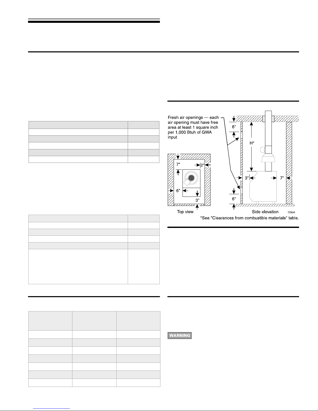
Figure 1 Minimum clearances
Clearances
Service clearances: Minimum
Top
(for cleaning flueways)
35"
Front
(for access to controls and components)
18"
Back 7"
Left side
(for cleaning and servicing)
24"
Right side 7"
Flooring and foundation
Flooring
The GWA boiler is approv ed for installation on combustib le flooring,
but must never be installed on carpeting.
Do not install boiler on carpeting even if foundation is
used. Fire can result, causing se vere personal injury ,
death or substantial property damage.
Foundation
1. Provide a solid brick or minimum 2-inch thick concrete
foundation pad if any of the following is true:
• floor can become flooded.
• the boiler mounting area is not level.
2. See T ab le 1 for minimum f oundation dimensions.
Residential garage installation
T ake the f ollowing special precautions when installing the boiler in
a residential garage. If the boiler is located in a residential garage,
per ANSI Z223.1, paragraph 5.1.9:
• Mount the boiler a minimum of 18 inches above the floor of the
garage to assure the burner and ignition devices will be no less
than 18 inches above the floor .
• Locate or protect the boiler so it cannot be damaged by a moving
vehicle.
Minimum clearance to combustible materials
1. Hot water pipes must be at least ½" from combustible material.
2. Single-wall vent pipe must be at least 6 inches from combustible
material.
3. Type B double-wall metal vent pipe — See v ent manufacturer’s
recommendation for clearances to combustible material.
Small space installations
1. When the boiler is located in a closet or small space, provide
clearances no less than those shown in Figure 1. The clearances
are required to any surface, whether combustible or noncombustible.
Table 1 Minimum foundation size
1 Prepare boiler location continued
Clearances from combustible materials: Minimum
Front (provide means of access) 3"
Back 7"
Left side (provide means ofaccess) 6"
Right side 2"
Top
GWA052 toGWA105
GWA140
GWA175
GWA210
GWA245
H
35"
35½"
38½"
39¾"
42½"
Boiler
model
Mini mu m
foundation
length
Mini mu m
foundation
width
GWA052 25" 12"
GWA070 25" 12"
GWA105 25" 15"
GWA140 25" 18"
GWA175 25" 21"
GWA210 25" 24"
GWA245 25" 27"

GW A
Gas-Fired Water Boilers – Boiler Manual
1 Prepare boiler location continued
Air contamination Air openings
Please review the following information on potential combustion air
contamination problems.
See Table 2 for products and areas which ma y cause contaminated
combustion air .
T o prev ent potential of severe personal injury or death,
check for products or areas listed below before
installing boiler. If any of these contaminants are found:
• Remove contaminants permanently .
— OR —
• Isolate boiler and provide outside combustion air . See
national, provincial or local codes for further
information.
Table 2 Corrosive contaminants and likely locations
Products to avoid
Spray cans containing chloro/fluorocarbons
Permanent wave solutions
Chlorinated waxes/cleaners
Chlorine-based swimming pool chemicals
Calcium chloride used for thawing
Sodium chloride used for water softening
Refrigerant leaks
Paint or varnish removers
Hydrochloric acid/muriatic acid
Cements and glues
Antistatic fabric softeners used in clothes dryers
Chlorine-type bleaches, detergents, and cleaning solvents found in
household laundry rooms
Adhesives used to fasten building products and other similar products
Combustion air and ventilation openings must comply with Section
5.3, “Air for Combustion and V entilation”, of National Fuel Gas Code
ANSI Z223.1–latest edition, or applicable local building codes.
Canadian installations must comply with B149.1 or B149.2
Installation Codes.
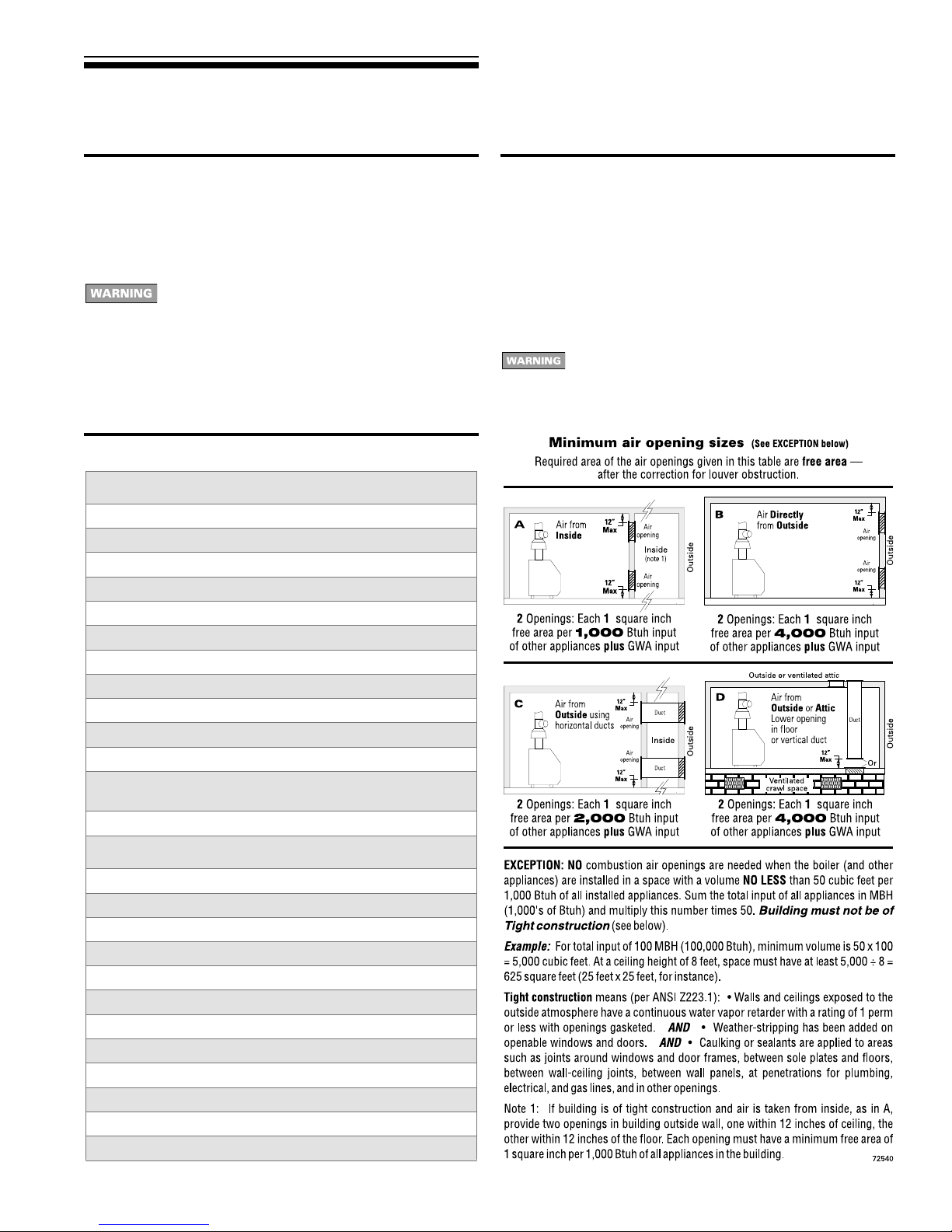
See table below for minimum combustion/ventilation air opening
sizes. Where openings are required, provide two (2) openings —
one within 12 inches of the ceiling, the other within 12 inches of the
floor, as shown in the tab le illustrations.
Provide adequate combustion and ventilation air to
assure proper combustion and reduce the risk of
severe personal injury , death or substantial property
damage caused by flue gas spillage and carbon
monoxide emissions.
Areas likely to have contaminants
Dry cleaning/laundry areas and establishments
Swimming pools
Metal fabrication plants
Beauty shops
Refrigeration repair shops
Photo processing plants
Auto body shops
Plastic manufacturing plants
Furniture refinishing areas and establishments
New building construction
Remodeling areas
Garages with workshops
5Part Number 670 01 1001 00

2 Prepare boiler continued
Pressure test
GW A
Gas-Fired Water Boilers – Boiler Manual
Perform h ydrostatic pressure test
Pressure test boiler before attaching water or gas piping or electrical
supply (except as noted below).
Prepare boiler for test
1. Remove the shipping nipple (from GWA supply tapping) and
remove the boiler relief valv e. Temporarily plug the relief valve
tapping with a ¾" NPT pipe plug.
2. Remove 1¼" nipple, reducing tee and drain valve from
accessory bag. Install in boiler return connection as shown on
in Figure 19, item 3, page 32. Install circulator on either the
return or supply .
3. Remove 1¼" nipple, 1¼" tee, bushing and pressure/temperature
gauge from accessory bag. Pipe to boiler supply connection as
shown in Figure 19, item 2, page 32. (Use pipe dope sparingly.)
4. Connect a hose to boiler drain valve, the other end connected
to a fresh water supply. Make sure hose can also be used to
drain boiler after test.
5. Connect a nipple and shutoff valve to system supply connection
on the 1¼" tee. This v alve will be used to bleed air during the fill.
(V alve and nipple are not included with boiler. )
6. Connect a nipple and shutoff valve to system return connection
(at circulator flange if circulator installed on return). This valv e
will be used to bleed air during the fill. (V alv e and nipple are not
included with boiler.)
7. Temporarily plug the air elimination tapping (next to supply
tapping).
Fill and pressure test
1. Open the shutoff valves you installed on supply and return
connections.
2. Slowly open boiler drain valve and fresh water supply to fill
boiler with water.
3. When water flows from shutoff valves, close boiler drain valve.
4. Close shutoff valves.
5. Slowly reopen boiler drain valve until test pressure of not more
than 45 psi is reached on the pressure/temperature gauge.
6. Test at no more than 45 psi f or no more than 10 minutes.
Do not leave boiler unattended. A cold water fill could
expand and cause excessive pressure, resulting in
severe personal injury , death or substantial property
damage.
7. Make sure constant gauge pressure has been maintained
throughout test. Check for leaks. Repair if found.
Leaks must be repaired at once. Failure to do so can
damage boiler, resulting in substantial property
damage.
Do not use petroleum-based cleaning or sealing
compounds in boiler system. Severe damage to boiler
will occur, resulting in substantial property damage.
Drain and remove fittings
1. Disconnect fill water hose from water source.
2. Drain boiler at drain valve or out hose, whichever provides best
access to drain. Remove hose after draining if used to drain
boiler.
3. Remove nipples, valves and plus unless they will remain for
use in the system piping.
4. Remove plug from relief valve tapping. See Section 3, page 10,
to replace relief valve.
7Part Number 670 01 1001 00

2 Prepare boiler continued
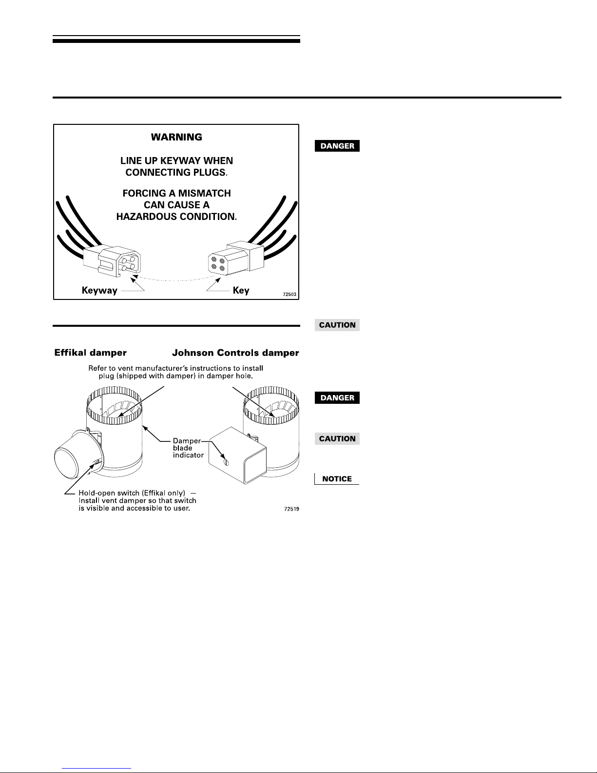
V ent damper continued
Figure 4 Vent damper assemblies
GW A
Gas-Fired Water Boilers – Boiler Manual
Damper installation
Do not modify draft hood or vent damper, or make
another connection between draft hood and vent
damper or boiler except as noted below . This will void
CSA certification and will not be covered by
Williamson-Thermoflo warranty. Any changes will
cause severe personal injury, death or substantial
property damage.
1. Install vent damper horizontally or vertically as shown in vent
damper manufacturer’s instructions. Vent damper must be
installed so that it serves only one boiler and so damper blade
indicator is visible to the user . See Figure 4.
2. Screws or rivets used to secure the vent damper to the draft
hood must not interfere with rotation of the damper blade.
3. Install damper harness between damper actuator and hole in
jacket left side panel. See Figure 3, page 8.
Use strain relief connectors and locknuts to secure both ends
of damper harness.
Keep wiring harness clear of all hot surfaces. Wire
insulation could be damaged, causing risk of electrical
short-circuit.
4. Read and apply the harness plug warning label (shown upperleft) so that it is visible after installation
5. Plug damper harness receptacle into damper harness plug.
Bypassing (jumpering) vent damper will cause flue
products such as carbon monoxide to escape into
the house. This will cause se vere personal injury or
death.
After boiler has operated once, if either end of harness
is disconnected, the system safety shutdown will
occur. The boiler will not operate until harness is
reconnected.
Effikal damper — Damper hold open switch must be
in Automatic Operation position for system to operate
properly .
9Part Number 670 01 1001 00

GW A
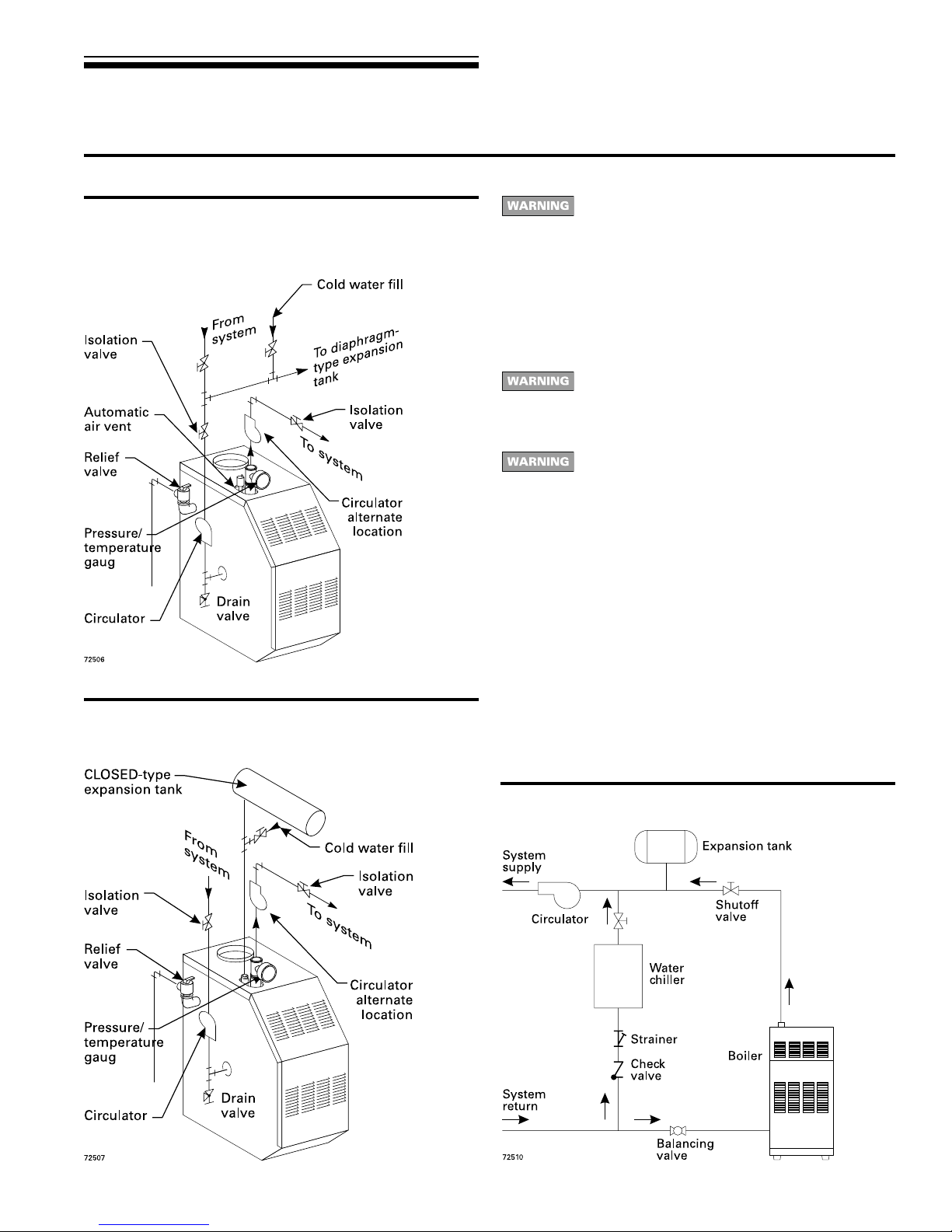
3 Install water piping continued
Near -boiler piping continued
Figure 5 Diaphragm- or bladder-type expansion tank:
Piping to single-zone system using
diaphragm-type or bladder-type expansion
tank. See Table 4 for piping sizes.
Gas-Fired Water Boilers – Boiler Manual
Use Figure 5 or Figure 6 only for systems designed
for return water at least 130 °F. F or systems with low
return water temperature possible, such as
converted gravity systems and radiant heating
systems, install bypass piping (see page 12) to
protect boiler against condensation. F ailure to prevent
low return water temperature to the boiler could cause
corrosion of the boiler sections or burners, resulting
in severe personal injury, death or substantial
property damage.
If system includes radiant heating circuits, provide
piping and controls to regulate the temperature
supplying the radiant circuits. Failure to comply could
result in substantial property damage.
Install boiler so that chilled medium is piped in parallel
with heating boiler (Figure 7). Use appropriate valves
to prevent chilled medium from entering boiler . Consult
I=B=R Installation and Piping Guides.
If boiler is connected to heating coils located in air
handling units where they can be exposed to
refrigerated air, use flow control valves or other
automatic means to prevent gravity circulation during
cooling cycle. Circulation of cold water through the
boiler could result in damage to the heat exchanger ,
causing possible severe personal injury, death or
substantial property damage.
Figure 6 Closed-type expansion tank: Piping to
single-zone system using closed-type
expansion tank. See Table 4 for piping sizes.
Water piping — refrigeration systems
Prevent chilled water from entering boiler
Install boiler so that chilled medium is piped in parallel with the
heating boiler. Use appropriate valves to prevent chilled medium
from entering boiler. See Figure 7 for typical installation of balancing
valve and check valve.
Figure 7 Piping refrigeration systems
11Part Number 670 01 1001 00
 Loading...