

ICP GPFM, PGS Installation Instructions Manual
I
Installation Instructions
PGF, PGS, & GPFM - 3 to 5 TON
3 Phase
Combination Units
Gas Heat / Electric Cool
509 01 1502 O0 10-22-01
Printed in U.S.A.
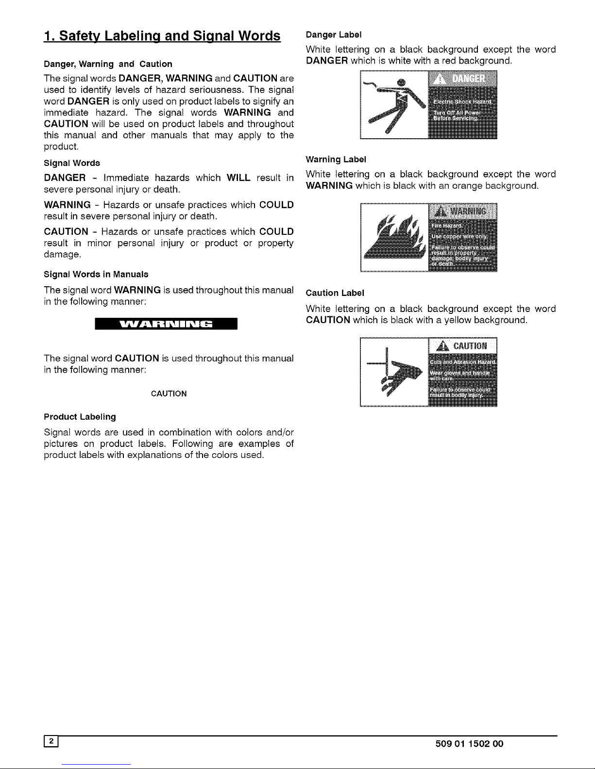
1. Safety Labelinq and Siqnal Words
Danger,Warning and Caution
The signal words DANGER, WARNING and CAUTION are
used to identify levels of hazard seriousness. The signal
word DANGER is only used on product labels to signify an
immediate hazard. The signal words WARNING and
CAUTION will be used on product labels and throughout
this manual and other manuals that may apply to the
product.
Signal Words
DANGER - Immediate hazards which WILL result in
severe personal injury or death.
WARNING - Hazards or unsafe practices which COULD
result in severe personal injury or death.
CAUTION - Hazards or unsafe practices which COULD
result in minor personal injury or product or property
damage.
Signal Words in Manuals
The signal word WARNING is used throughout this manual
in the following manner:
The signal word CAUTION is used throughout this manual
in the following manner:
CAUTION
Product Labeling
Signal words are used in combination with colors and/or
pictures on product labels. Following are examples of
product labels with explanations of the colors used.
Danger Label
White lettering on a black background except the word
DANGER which is white with a red background,
Warning Label
White lettering on a black background except the word
WARNING which is black with an orange background,
Caution Label
White lettering on a black background except the word
CAUTION which is black with a yellow background,
J2J 509 01 150200
3 TO 5 TON
49 - 3/4
19
I
5-3/16
2-3/16
©
BASE RAIL
12-1/4 --
SUPPLY
BASE PAN - A CHASIS
BASE RAIL
19
12-1/4
RETURN
3-3/4
ALL DIMENSIONSININCHES
Connections Detail
(_ 2-1/4"
AS
CONNECTION
1/2" PiPE
LOW
_- 1--_4"VOLTAGE
_ 1/2"CONDUI'[
4"J<F-- ELECTRICAL
POWER
CONDUIT
2-3/16
UNITSIZE
3TO 5Ton
** Mearsured from inside to inside an base rails.
509 01 1502 00 13
3. SAFE INSTALLATION REQUIREMENTS
Installation or repairs made by unqualified persons can result
in hazards to you and others. Installation MUST conform with
local building codes or, in the absence of local codes, with the
ANSI Z223.1 and the National Electrical Code NFPA70-1990 or
in Canada the National Standard CAN/CGA B149-1 and CSA
C.22.1 - Canadian Electrical Code Part 1.
The information contained in this manual is intended for use
by a qualified service technician familiar with safety proce-
dures and equipped with the proper tools and test instru-
ments.
Failure to carefully read and follow all instructions in this
manual can result in furnace malfunction, property damage,
personal injury and/or death.
• Do NOT use this furnace as a construction heater.
• Use only the Type of gas approved for this furnace (See
Rating Plate).
• Do NOT use open flame to test for gas leak.
• Seal supply and return air ducts.
• Check to see that filters are installed correctly and are
the proper type an size.
NOTE: It is the personal responsibility and obligation of the
customer to contact a qualified installer to ensure that the
installation is adequate and conforms to governing codes
and ordinances.
CAUTION
It is recommended that a qualified service technician
check the heat exchanger integrity every two (2) years,
after the first four (4) years of operation.
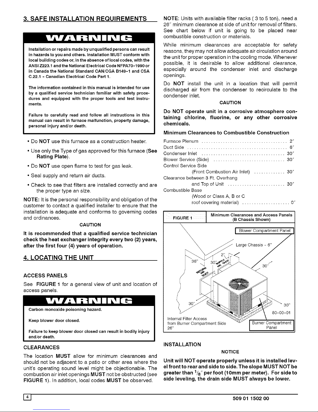
4. LOCATING THE UNIT
ACCESS PANELS
See FIGURE 1 for a general view of unit and location of
access panels.
Carbon monoxide poisoning hazard.
Keep blower door closed.
Failure to keep blower door closed can result in bodily injury
and/or death.
CLEARANCES
The location MUST allow for minimum clearances and
should not be adjacent to a patio or other area where the
unit's operating sound level might be objectionable. The
combustion air inlet openings MUST not beobstructed (see
FIGURE 1). In addition, local codes MUST be observed.
NOTE: Units with available filter racks ( 3 to 5 ton), need a
26" minimum clearance at side of unit for removal of filters.
See chart below if unit is going to be placed near
combustible construction or materials.
While minimum clearances are acceptable for safety
reasons, they may not allow adequate air circulation around
the unit for proper operation in the cooling mode. Whenever
possible, it is desirable to allow additional clearance,
especially around the condenser inlet and discharge
openings.
Do NOT install the unit in a location that will permit
discharged air from the condenser to recirculate to the
condenser inlet.
CAUTION
Do NOT operate unit in a corrosive atmosphere con-
taining chlorine, fluorine, or any other corrosive
chemicals.
Minimum Clearances to Combustible Construction
Furnace Plenum .................................... 2"
Duct Side .......................................... 6"
Condenser Inlet ................................... 30"
Blower Service (Side) .............................. 30"
Control Service Side
(Front Combustion Air Inlet) ............. 30"
Clearance between 3 Ft. Overhang
and Top of Unit ........................ 30"
Combustible Base
(Wood or Class A, B or C
roof covering material) .................... 0"
FIGURE i Minimum Clearances(BChassisandshown)ACcessPanels
I Blower Compartment Panel
Large Chassis - 6"
80-00-01
Internal Filter Access
from Burner Compartment Side Burner Compartment
26" Panel
INSTALLATION
NOTICE
Unit will NOT operate properly unless it is installed lev-
el front to rear and side to side. The slope MUST NOT be
greater than 1/8"per foot (10mm per meter). For side to
side leveling, the drain side MUST always be lower.
141 509 01 1502 00
Ground Level Installation
Ground level platform requirements:
- The unit MUST be situated to provide safe access for
servicing.
Platform may be made of either concrete or pressure
treated wood and MUST be level and strong enough to
support unit weight.
Position platform separate from building foundation.
Install in well-drained area, with top surface of platform
above grade level.
Platform must be high enough to allow for proper con-
densate trap installation and drainage. See FIGURE 3
and associated text for more information about conden-
sate drainage.
Rooftop Installation
Rooftop platform requirements:
- The unit MUST be situated to provide safe access for
servicing.
- The existing roof structure MUST be adequate to sup-
port the weight of the unit or the roof MUST be
reinforced.
Check the weight of the unit in relation to the roof struc-
ture and local building codes or ordinances and
reinforce roof structure if necessary. See the last page
of this manual for unit weights.
- Support for the unit MUST be level and strong enough
to carry unit weight. The support may consist of a plat-
form or a combination of platform and roof beams or
curb,
- See Hoisting section for hoisting instructions,
HOISTING
NOTE: All access panels MUST be secured in place before
hoisting.
The unit should be hoisted with two lifting slings. Attach the
slings to rigging shackles that have been hooked through
holes in the base rail.
Two spreader bars MUST be placed on top of the unit to
protect the unit from damage from the pressure exerted by
the slings. Make sure that all equipment is adequate to
handle the weight of the unit and that the slings will not allow
the unit to shift.
Refer to FIGURE 17 on the back cover of this manual for
illustrated rigging instructions and weight chart.
DOWNFLOW CONVERSION
NOTE: In downflow applications with roof curbs or jack
stands, the center rail under the unit must be removed. The
center rail is attached to the base rail with screws.
These units are adaptable to downflow use, To convert to
downflow use, follow these steps:
1. Remove the blockoff plates found in the return air
compartment and the supply air compartment.
2. Install the removed plates on the horizontal return and
supply air openings.
3, Install roof curb on the building. Be sure to follow all
directions included with curb and all applicable building
codes in your installation,
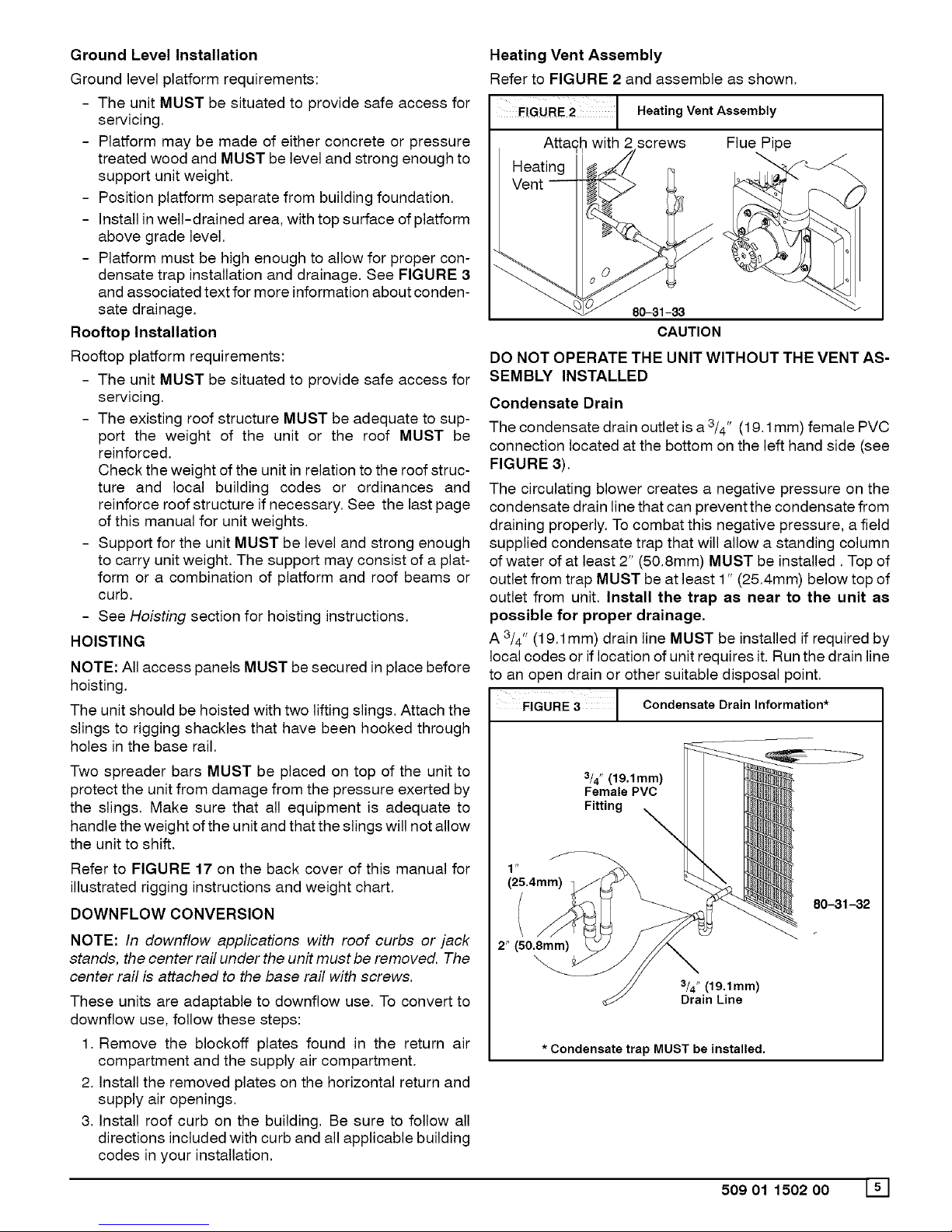
Heating Vent Assembly
Refer to FIGURE 2 and assemble as shown.
FiGuRE2 1 HeatingVentAssembly
Atta£b with 2 screws
Heating
Vent
80-31-33
CAUTION
Flue Pipe
DO NOT OPERATE THE UNIT WITHOUT THE VENT AS-
SEMBLY INSTALLED
Condensate Drain
The condensate drain outlet is a 3/4" (19.1 mm) female PVC
connection located at the bottom on the left hand side (see
FIGURE 3).
The circulating blower creates a negative pressure on the
condensate drain line that can prevent the condensate from
draining properly. To combat this negative pressure, a field
supplied condensate trap that will allow a standing column
of water of at least 2" (50.8mm) MUST be installed. Top of
outlet from trap MUST be at least 1" (25.4mm) below top of
outlet from unit, Install the trap as near to the unit as
possible for proper drainage,
A3/4" (19.1mm) drain line MUST be installed if required by
local codes or if location of unit requires it. Run the drain line
to an open drain or other suitable disposal point.
3 | Condensateora n nformat on*
$
(25.4mm)
3/4" (19,1mm)
Female PVC
Fitting X
80-31-32
2" (50.8mm)
_4"(19.1mm)
Drain Line
* Condensate trap MUST be installed.
509 01 1502 00 W

5. PRE-EXISTING COMMON VENT CHECK
If the installation of the combination unit involves removing
an existing furnace from a common vent with other
appliances, the existing venting system will probably be too
large for the remaining appliances and they will not vent
properly. The existing venting system MUST be checked by
a qualified technician to ensure it is properly sized and
vents properly.
6. GAS SUPPLY AND PIPING
NOTE: Because there are many types of liquified petroleum
(LP) gases, the term LP as used in this manual refers to
propane gas. If you intend to use any type of LP gas, proper
precautions MUST be used in the handling, piping, and use
of such gas.
The UL/CSA Rating Plate located on the side panel on the
unit contains the model number, type of gas and gas input
rating, and other important information.
Fire and/or explosion hazard.
Make certain the unit is equipped to operate onthe type of gas
available. Models designated as natural gas are to be usedwith
naturalgasonly. Modelsdesignated for use with liquefiedpetro-
leum (LP) gasare shipped with orifices sizedfor commercially
pure propanegas.They MUST not be usedwith butane ora mix-
ture of butane and propane unless properly sized orifices are
installed by a licensed LPinstaller.
Failure to follow this warning can result in property damage,
_ersonal injury,and/or death.
GAS PIPING
The gas supply line MUST be of adequate size to handle the
Btu/hr requirements and length of the run for the unit being
installed. Determine the minimum pipe size for natural gas
from the table in FIGURE 4 or FIGURE 5. Base the length
of the run from the gas meter or source to the unit.
Gas Pipe Size
Btu ratings of all other gas appliances MUST be considered
for sizing of main gas line. Check gas line to installation for
compliance with local codes or, in the absence of local
codes, with the National Fuel Gas Code ANSI Z223.1 or in
Canada the National Standard CAN/CGA B149-1 or
current editions.
FIGURE 4 Gas Pipe Size, Length and Btu/hr Capacity
for Schedule 40 Iron Pipe (English)
NATURAL GAS
Pipe Length Btu/hr (in thousands)
(Includes
Fittings) 3/4" 1" 11/4" 11/2" 2"
20' 190 350 730 1,100 2,100
40' 130 245 500 760 1,450
60' 105 195 400 610 1,150
LP GAS
Pipe Length Btu/hr (in thousands)
(Includes
Fittings) 1/2" 3/4" 1 " 11/4" 11/2"
20' 189 393 732 1,496 2,299
40' 129 267 504 1,039 1,559
60' 103 217 409 834 1,275
Gas Pipe Size, Length and Btu/hr Capacity
FIGURE 5
for Schedule 40 Iron Pipe (English)
Pipe Length
(Includes
Fittings)
6.1m
NATURAL GAS
kW**
1" 11/4" 11/2"
103 214 322
72 147 223
57 117 179
3/4" 2"
56 615
12.2m 38 425
18.3m 31 337
LP GAS
Pipe Length kW**
(Includes
Fittings) 1/2" 3/4" 1 " 11/4" 11/2"
6.1m 55 115 215 438 674
12.2m 38 78 148 305 457
18.3m 30 64 120 244 374
**kW (Kilowatts) is the metric equivalent of Btu/hr.
PIPING AT UNIT
Connections
NOTE: The rules listed apply to natural and LP gas pipe
installations.
1. If installation is for LP gas, have LP gas installer use
TWO-STAGE REGULATION and make all connec-
tions from storage tank to unit.
2. Use black iron or steel pipe and fittings or other pipe ap-
proved by local code.
3. If copper tubing is used, it MUST comply with limitation
set in Fuel Gas Code.
NOTE: If a gas connector is used, it MUST be acceptable to
local authority. Connector MUST NOT be used inside the
furnace or be secured or supported by the furnace or
ductwork.
Fire and/or explosion hazard.
Gas connector MUST be properly installed and can NOT be
used inside the furnace.
Failure to do so can result in property damage, bodily injury or
death.
4. Use pipe joint compound on external (male) threads
ONLY. Joint compound MUST be resistant to any
chemical action of LP gases. Do NOT put pipe com-
pound on last 2 threads of pipe.
5. Use ground joint unions and install a drip leg no less
than 3 inches (76 mm) long to trap dirt and moisture be-
fore it can enter gas valve.
CAUTION
Overtightening assembly may cause damage to the
gas valve and/or wiring and may misalign the burners,
6. Use a wrench on gas valve when making connections
to prevent gas valve from turning. Do NOT use a pipe
wrench on the gas valve body.
7. Provide a 1/8 inch (3mm) National Pipe Thread (NPT)
plug for test gauge connection immediately upstream of
161 509 01 1502 O0
 Loading...