

Page 1
NTC6/GNE
Upflow/Horizontal
220V-1ph-50Hz
SAFETY REQUIREMENTS
Recognize safety information. This is the safety-alert symbol/ ._\,. When you see this symbol on the furnace and in instructions
manuals be alert to the potential for personal injury.
Understand the signal words DANGER, WARNING, or CAUTION. These words are used with the safety-alert symbol. DANGER
identifies the most serious hazards, those that will result in severe personal injury or death. WARNING signifies a hazard that could
result in personal injury or death. CAUT__Nisusedt_identifyunsafe_racticesthatc_u_dresu_tinmin_r_ers_na_injury_r_r_ductand
property damage.
Installing and servicing heating equipment can be hazardous due to gas and electrical components. Only trained and qualified person-
nel should install, repair, or service heating equipment.
Untrained service personnel can perform basic maintenance functions such as cleaning and replacing air filters. All other operations
must be performed by trained service personnel. When working on heating equipment, observe precautions in the literature, on tags,
and on labels attached to or shipped with the unit and other safety precautions that may apply.
Follow all national and local safety codes. In the United States, follow all safety codes including the current edition National Fuel Gas
Code (NFGC) NFPA No. 54/ANSIZ223.1. In Canada, refer to the current edition of the National Standard Canada CAN/CGA-B149.1 -
and .2-M91 Natural Gas and Propane Installation Codes (NSCNGPIC). Wear safety glasses and work gloves. Have fire extinguisher
available during start-up and adjustment procedures and service calls.
These instructions cover minimum requirements and conform to existing national standards and safety codes. In some instances,
these instructions exceed certain local codes and ordinances, especially those that may not have kept up with changing residential
construction practices. We require these instructions as a minimum for a safe installation.
,IX
Table of Contents
1.Installation ............................... 2
2.Combustion&VentilationAir ................. 4
3.GasVentInstallation ....................... 6
4.HorizontalVenting ......................... 8
5.GasSupply andPiping...................... 8
Manufactured by:
International Comfort Products Corporation (USA)
Lewisburg, TN USA 37091
6. ElectricalWiring ........................
7. DuctworkandFilter .....................
8. ChecksandAdjustments .................
9. FurnaceMaintenance....................
homes, trailers or recreational vehicles. Such
use could result in property damage, bodily in-
I his furnace is not designed for use in mobile
jury and/or death.
12
13
14
16
LP1 2/4/2002 441 01 2307 01
Page 2
1. Installation
Installation or repairs made by unqualified persons
can result in hazards to you and others. Installation
MUST conform with local codes or, in the absence
of local codes, with codes of all governmental
authorities having jurisdiction.
The information contained in this manual is
intended for use by a qualified service technician
who is experienced in such work, who is familiar
with all precautions and safety procedures
required in such work, and is equipped with the
proper tools and test instruments.
Failure to carefully read and follow all instructions
in this manual can result in furnace malfunction,
property damage, personal injury and/or death.
NOTE: Refer to the appropriate codes, along with this manual,
for proper installation.
water heaters, furnaces, gas-fired fireplaces, wood fire-
places, and several other items. Carbon monoxide can
cause serious bodily injury and/or death. Therefore, to
help alert people of potentially dangerous carbon monox-
ide levels, you should have carbon monoxide detectors
listed by a nationally recognized agency (e.g. Underwrit-
ers Laboratories or International Approval Services)
installed and maintained in the building or dwelling (see
Note below).
B,
There can be numerous sources of fire or smoke in a build-
ing or dwelling. Fire or smoke can cause serious bodily in-
jury, death, and/or property damage. Therefore, in order to
alert people of potentially dangerous fire or smoke, you
should have fire extinguisher and smoke detectors listed
by Underwriters Laboratories installed and maintained in
the building or dwelling (see Note below).
Note: The manufacturer of your furnace does not test any detec-
tors and makes no representations regarding any brand
or type of detector.
• This furnace is NOT approved for installation in mo-
bile homes, trailers or recreation vehicles.
• Do NOT use this furnace as a construction heater or to
heat a building that is under construction.
Use only the Type of gas approved for this furnace (see
Rating Plate on unit). Overfiring will result in failure of heat
exchanger and cause dangerous operation. (Furnace can
be converted to L.R gas with approved kit.)
• Do NOT use open flame to test for gas leak.
• Ensure adequate combustion and ventilation air is pro-
vided to the furnace.
• Seal supply and return air ducts.
• The vent system MUST be checked to determine that it is
the correct type and size.
• Install correct filter type and size.
• Unit MUST be installed so electrical components are pro-
tected from direct contact with water.
• It is the suggestion of this manufacturer to install fire and
carbon monoxide detectors.
C. To ensure safe and efficient operation of your unit, you
should do the the following:
1. Thoroughly read this manual and labels on the unit.
This will help you understand how your unit operates and
the hazards involved with gas and electricity.
2. Do not use this unit if any part has been under water.
Immediately call a qualified service technician to inspect
the unit and to replace any part of the control system and
any gas control which has been under water.
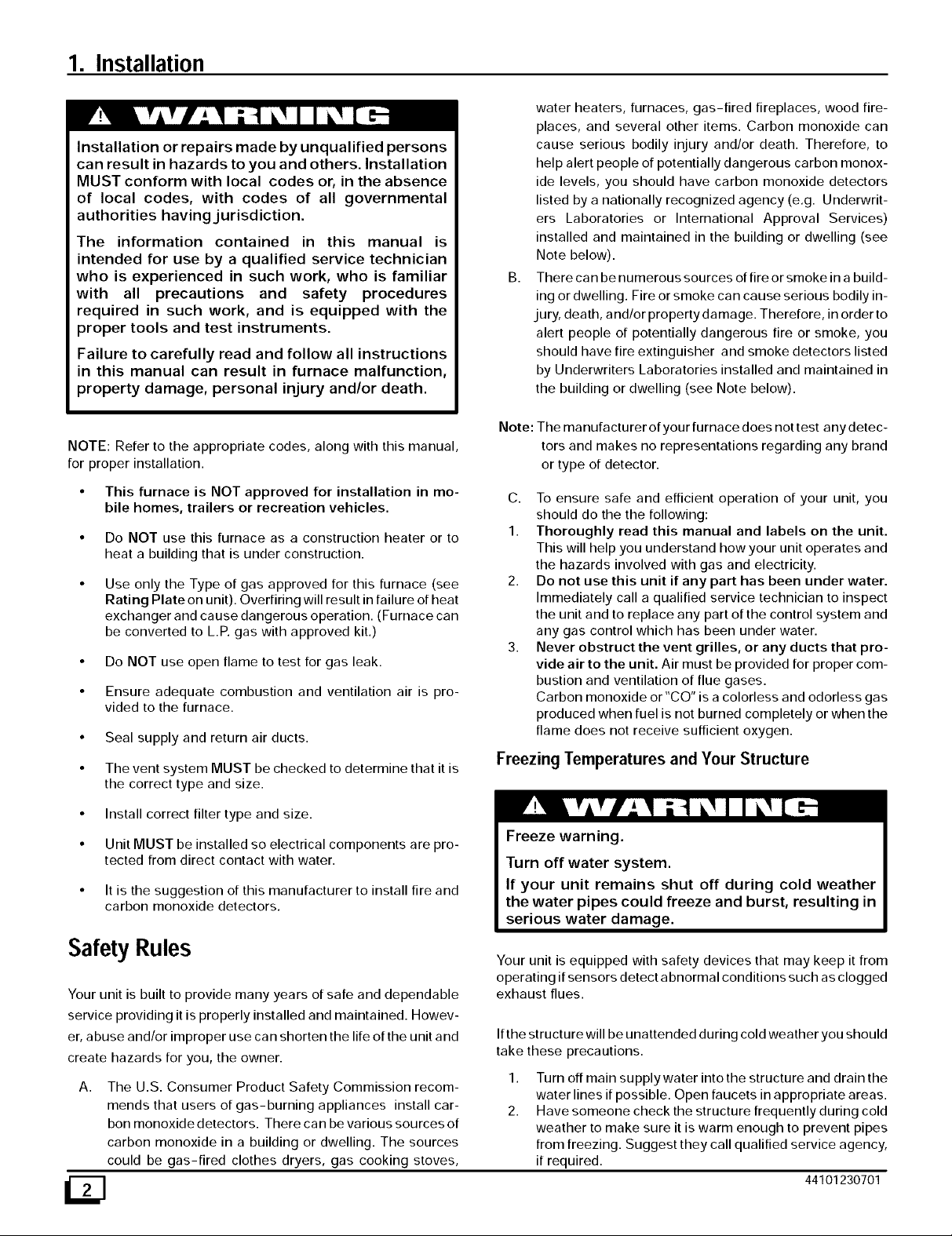
3. Never obstruct the vent grilles, or any ducts that pro-
vide air to the unit. Air must be provided for proper com-
bustion and ventilation of flue gases.
Carbon monoxide or"CO" is a colorless and odorless gas
produced when fuel is not burned completely or when the
flame does not receive sufficient oxygen.
Freezing Temperatures and Your Structure
Freeze warning.
Turn off water system.
If your unit remains shut off during cold weather
the water pipes could freeze and burst, resulting in
serious water damage.
Safety Rules
Your unit is built to provide many years of safe and dependable
service providing it is properly installed and maintained. Howev-
er, abuse and/or improper use can shorten the life of the unit and
create hazards for you, the owner.
A. The U.S. Consumer Product Safety Commission recom-
mends that users of gas-burning appliances install car-
bon monoxide detectors. There can be various sources of
carbon monoxide in a building or dwelling. The sources
could be gas-fired clothes dryers, gas cooking stoves,
Your unit is equipped with safety devices that may keep it from
operating if sensors detect a bnormal conditions such as clogged
exhaust flues.
If the structure will be unattended during cold weather you should
take these precautions.
1. Turn off main supply water into the structure and drain the
water lines if possible. Open faucets in appropriate areas.
2. Have someone check the structure frequently during cold
weather to make sure it is warm enough to prevent pipes
from freezing. Suggest they call qualified service agency,
if required.
44101230701
Page 3
Location and Clearances
Poison carbon monoxide gas hazard.
If this furnace is replacing a previously
common-vented furnace, it may be necessary to
resize the existing vent line and chimney to
prevent oversizing problems for the other
remaining appliances(s). See applicable codes
and Venting and Combustion Air Check in Gas
Vent Installation section.
Failure to properly vent this furnace or other
appliances can result in property damage,
personal injury and/or death.
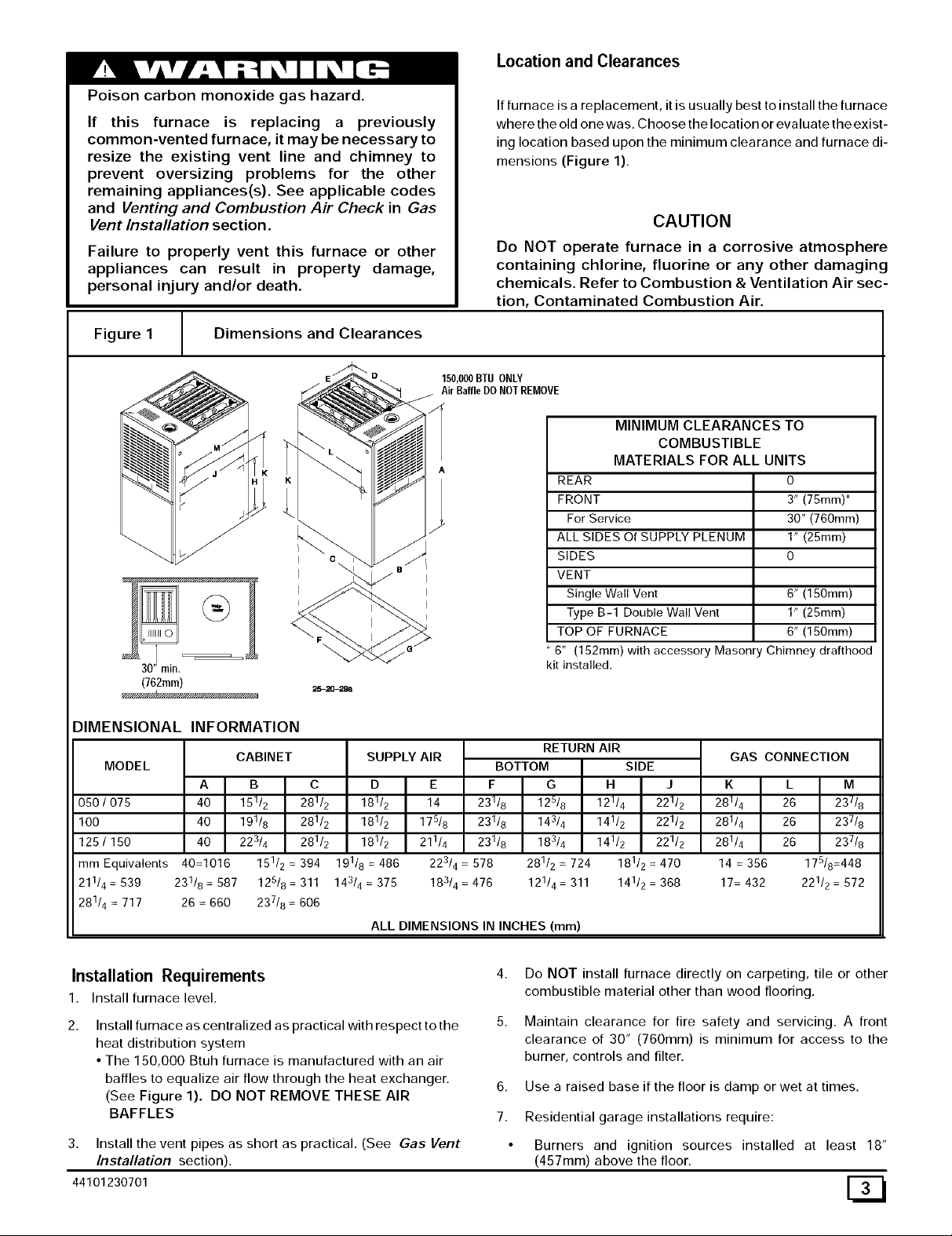
Figure 1 Dimensions and Clearances
IIIIIIIII0
=
i
1
30" rain.
(762rata)
25-2(]-29a
If furnace is a replacement, it is usually best to install the furnace
where the old one was. Choose the location or evaluate the exist-
ing location based upon the minimum clearance and furnace di-
mensions (Figure 1).
Do NOT operate furnace in a corrosive atmosphere
containing chlorine, fluorine or any other damaging
chemicals. Refer to Combustion & Ventilation Air sec-
tion, Contaminated Combustion Air.
150,000BTUONLY
AirBaffleDONOTREMOVE
/¢
CAUTION
MINIMUM CLEARANCES TO
COMBUSTIBLE
MATERIALS FOR ALL UNITS
REAR 0
FRONT 3" (75ram)*
For Service 30" (760mm)
ALL SIDES Of SUPPLY PLENUM 1" (25mm)
SIDES 0
VENT
Single Wall Vent 6" (150mm)
Type B-1 Double Wall Vent 1" (25ram)
TOP OF FURNACE 6" (150mm)
6" (152mm) with accessory Masonry Chimney drafthood
kit installed.
DIMENSIONAL INFORMATION
MODEL
A K L M
050 / 075 40 281/4 26 23_/8
100 40 281/4 26 237/8
125 / 150 40 281/4 26 237/8
mm Equivalents 40=1016 14 = 356 178/8=448
211/4 = 539 231/8 = 587 125/8 = 311 17= 432 221/2 = 572
281/4 = 717 26 = 660 237/8 = 606
B C D
151/2 281/2 181/2
191/8 281/2 181/2
223/4 281/2 181/2
151/2 = 394 191/8 = 486
SUPPLY AIRCABINET
E F G
14 231/8 125/8
175/8 231/8 143/4
211/4 231/8 183/4
223/ =578 281/2=724
143/4 = 375
ALL DIMENSIONS IN INCHES (mm)
183/4 = 476 121/4 = 311
BOTTOM
Installation Requirements
1. Install furnace level.
2.
Install furnace as centralized as practical with respect to the
heat distribution system
• The 150,000 Btuh furnace is manufactured with an air
baffles to equalize air flow through the heat exchanger.
(See Figure 1). DO NOT REMOVE THESE AIR
BAFFLES
3.
Install the vent pipes as short as practical. (See Gas Vent
Installation section).
44101230701
RETURN AIR
SIDE
H J
121/4 221/2
141/2 221/2
141/2 221/2
181/2 = 470
141/2 = 368
4.
Do NOT install furnace directly on carpeting, tile or other
GAS CONNECTION
combustible material other than wood flooring.
5.
Maintain clearance for fire safety and servicing. A front
clearance of 30" (760mm) is minimum for access to the
burner, controls and filter.
6. Use a raised base if the floor is damp or wet at times.
7. Residential garage installations require:
• Burners and ignition sources installed at least 18"
(457mm) above the floor.
[33
Page 4
• Furnace must be located or physically protected from pos-
sible damage by a vehicle.
Horizontal Furnace Installation
IMPORTANT
NOTE: Inspect unit rating plate to be certain model number be-
gins with "NTC6 or GNE', This identifies unit as horizontally
mountable, If unit does NOT bear this designation, you may NOT
mount this unit horizontally, Horizontal furnace may not be
mounted on its back,
If you purchased a horizontally mountable furnace, it can be
installed horizontally in an attic, basement, crawl space, alcove,
or suspended from a ceiling in a basement or utility room in either
a right or left airflow position. See Figure 2.
Thirty inches (30") (760mm) between the front of the furnace and
adjacent construction or other appliances MUST be maintained
for service clearance.
Keep all insulating materials clear from Iouvered door. Insulating
materials may be combustible.
The horizontal furnaces may be installed directly on combustible
wood flooring or supports, however it is recommended for further
fire protection that cement board or sheet metal is placed be-
tween the furnace and the combustible wood floor and extend
12" (300mm) beyond the front of the furnace louver door. (This is
a recommendation only, not a requirement).
This furnace MUST NOT be installed directly on carpeting or tile
or other combustible material other than wood flooring or sup-
ports.
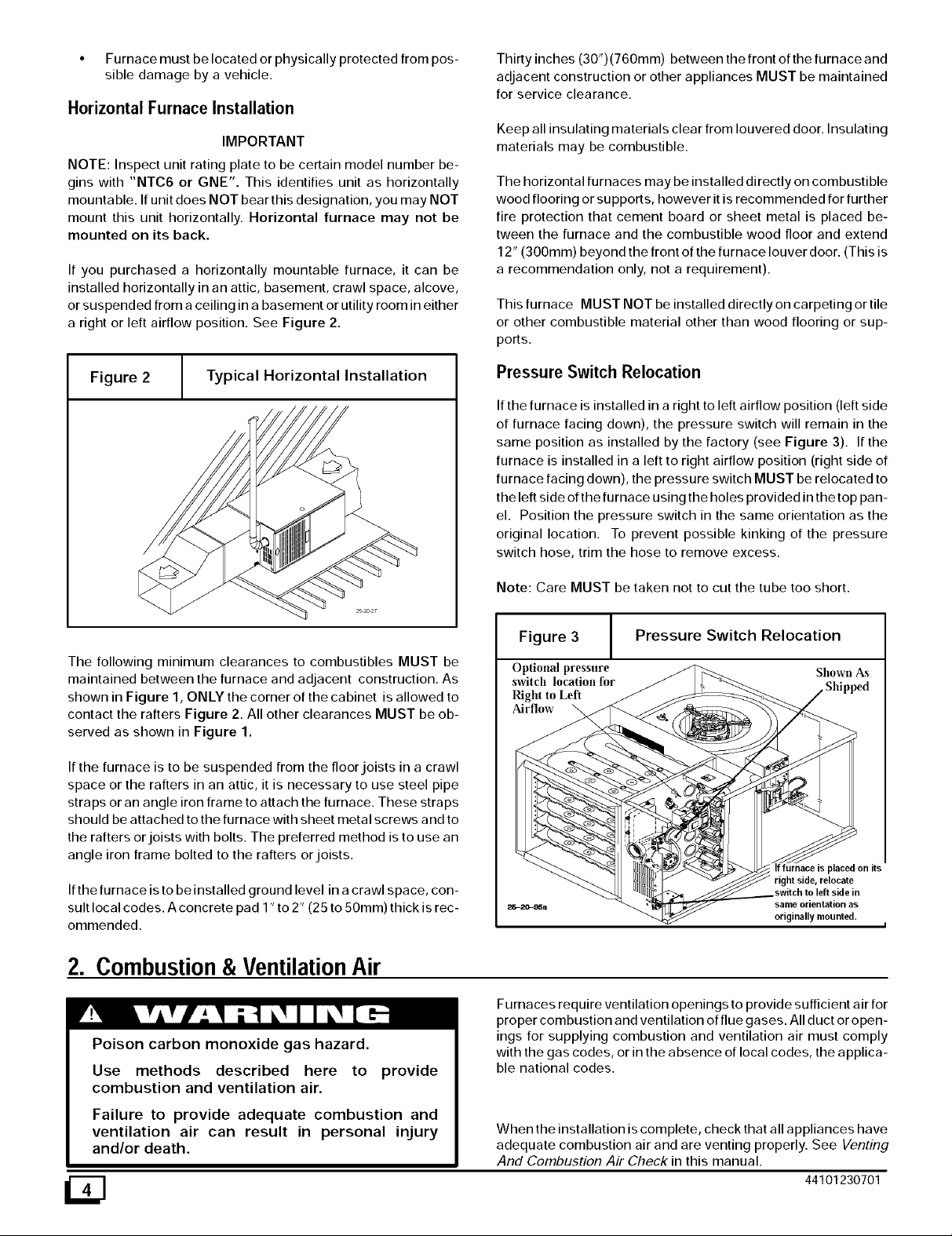
Figure 2 Typical Horizontal Installation
The following minimum clearances to combustibles MUST be
maintained between the furnace and adjacent construction. As
shown in Figure 1, ONLY the corner of the cabinet is allowed to
contact the rafters Figure 2. All other clearances MUST be ob-
served as shown in Figure 1.
If the furnace is to be suspended from the floor joists in a crawl
space or the rafters in an attic, it is necessary to use steel pipe
straps or an angle iron frame to attach the furnace. These straps
should be attached to the furnace with sheet metal screws and to
the rafters or joists with bolts. The preferred method is to use an
angle iron frame bolted to the rafters or joists.
If the furnace is to be installed ground level in a crawl space, con-
sult local codes. A concrete pad 1" to 2" (25 to 50ram) thick is rec-
ommended.
Pressure Switch Relocation
If the furnace is installed in a right to left airflow position (left side
of furnace facing down), the pressure switch will remain in the
same position as installed by the factory (see Figure 3). If the
furnace is installed in a left to right airflow position (right side of
furnace facing down), the pressure switch MUST be relocated to
the left side of the furnace using the holes provided in the top pan-
el. Position the pressure switch in the same orientation as the
original location. To prevent possible kinking of the pressure
switch hose, trim the hose to remove excess.
Note: Care MUST be taken not to cut the tube too short.
Figure 3 [
Optional pressure
switch location for
Right to Left
Airflow
Pressure Switch Relocation
Shown As
right side, relocate
same orientation as
originally mounted.
2. Combustion & VentilationAir
Poison carbon monoxide gas hazard.
Use methods described here to provide
combustion and ventilation air.
Failure to provide adequate combustion and
ventilation air can result in personal injury
and/or death.
D
Furnaces require ventilation openings to provide sufficient air for
proper combustion and ventilation of flue gases. All duct or open-
ings for supplying combustion and ventilation air must comply
with the gas codes, or in the absence of local codes, the applica-
ble national codes.
When the installation is complete, check that all appliances have
adequate combustion air and are venting properly. See Venting
And Combustion Air Check in this manual.
44101230701
Page 5
Contaminated Combustion Air
Confined Space Installation
Installations in certain areas or types of structures will increase
the exposure to chemicals or halogens that may harm the fur-
nace. These instances must use only outside air for combustion.
The following areas or types of structures may contain or have
exposure to the substances listed below. The installation must be
evaluated carefully as it may be necessary to provide outside air
for combustion.
• Commercial buildings.
• Buildings with indoor pools.
• Furnaces installed in laundry rooms.
• Furnaces installed in hobby or craft rooms.
• Furnaces installed near chemical storage areas.
• Permanent wave solutions for hair.
• Chlorinated waxes and cleaners.
• Chlorine based swimming pool chemicals.
• Water softening chemicals.
• De-icing salts or chemicals.
• Carbon tetrachloride.
• Halogen type refrigerants.
• Cleaning solvents (such as perchloroethylene).
• Printing inks, paint removers, varnishes, etc..
• Hydrochloric acid.
• Sulfuric Acid.
• Solvent cements and glues.
• Antistatic fabric softeners for clothes dryers.
• Masonry acid washing materials.
NOTE: A confined space is defined as an area with less than 50
cubic feet(1.4m 3) per 1,000 BTUH input rating for all gas ap-
pliances installed in the area.
Air Openings and Connecting Ducts
1. Total input rating for all gas appliances MUST be considered
when determining free area of openings.
2. Connect ducts or openings directly to outside.
3. When screens are used to cover openings, the openings
MUST be no smaller than 114" (6mm) mesh.
4. The minimum dimension of rectangular air ducts MUST
NOT be less than 3" (75mm).
5. When sizing grille or louver, use the free area of opening. If
free area is NOT stamped or marked on grill or louver, as-
sume a 20% free area for wood and 60% for metal.
Requirements
1. Provide confined space with sufficient air for proper com-
bustion and ventilation of flue gases using horizontal or ver-
tical ducts or openings.
2. Figure4 illustrateshowtoprovidecombustionandventila-
tion air. A minimum of two permanent openings, one inlet
and one outlet, are required.
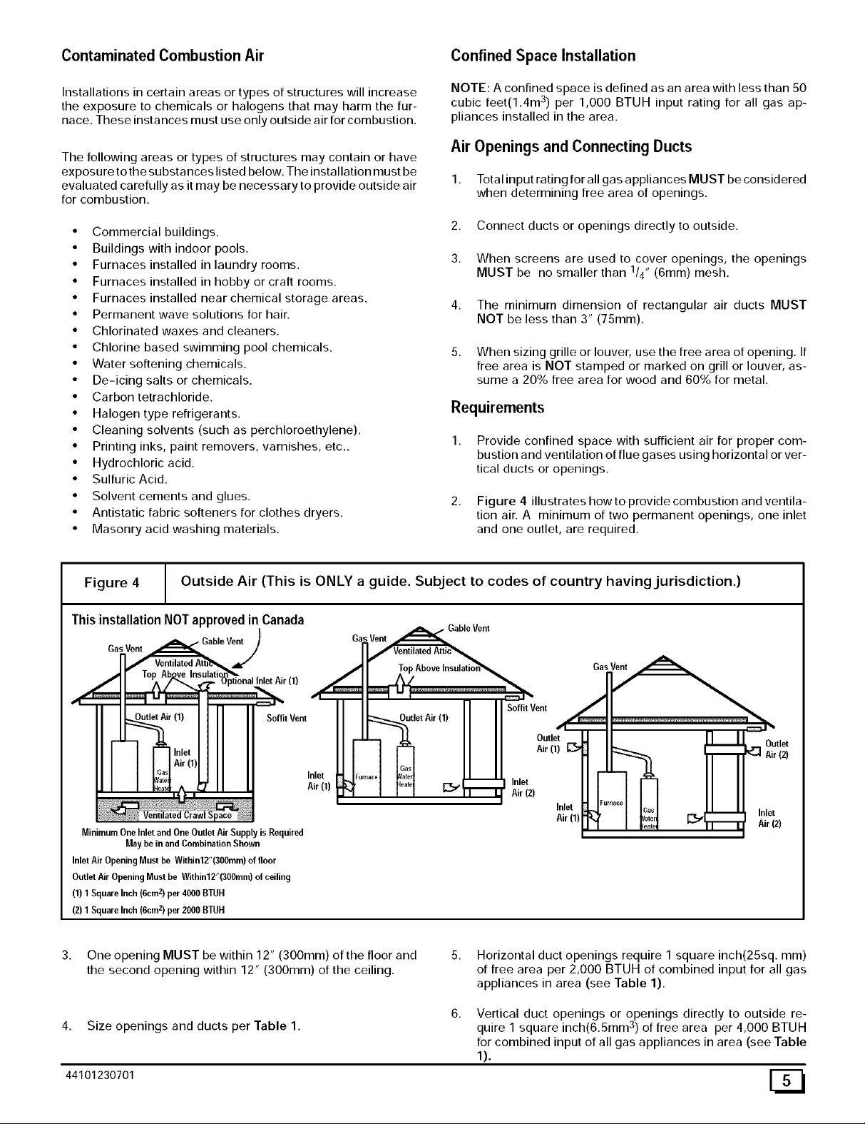
Figure 4 Outside Air (This is ONLY a guide. Subject to codes of country having jurisdiction.)
ThisinstallationNOTapprovedinCanada
Gas Vent
MinimumOne Inlet andOne Outlet AirSupply isRequired
InletAir OpeningMust be Within12"(300mm)of floor
OutletAir OpeningMustbe Within12"(300mm)of ceiling
(1) 1Square Inch(6cmz)per4000BTUH
(2) 1Square Inch(6cmz)per2000BTUH
3,
May be inand Combination Shown
One opening MUST be within 12" (300mm) of the floor and
the second opening within 12" (300mm) of the ceiling.
Gable Vent
Soffit Vent
.4,
JI
I I ' N So_flt_ent
I ut'etAir")II
I _ J_ H I Outlet
J _ III Air(')_
Inlet
._J_'"_°l F;_I r-,,.,r'_" Inlet
Air (1)
J"l I I I _ _ Air(2)
5. Horizontal duct openings require 1 square inch(25sq, mm)
of free area per 2,000 BTUH of combined input for all gas
appliances in area (see Table 1).
iFurnace
Inlet
Air(1}
_ 3as m
'atel _
eat_ rim
Outlet
Air (2)
Inlet
Air (2)
4. Size openings and ducts per Table 1.
44101230701
Vertical duct openings or openings directly to outside re-
u 3
q ire 1 square inch(6.5mm ) of free area per 4,000 BTUH
for combined input of all gas appliances in area (see Table
1).
CZl
Page 6

Table1
BTUH In-
putRat- HorizontalDuct
ing (2,000BTUH)
50,000 161cm2(25sq. in.)
75,000 242cmz (35.5sq. in.)
100,000 323 cmz (50 sg, in.)
125,000 403 cm 2 (62.5 sg. in.)
150,000 484 cmz (71 sg. in.)
FreeArea
MinimumFreeArea Requiredfor EachOpening
VerticalDuctoropenings
to outside
(4,000BTUH)
81cmz (12.5sq, in.)
121cmz (18.75sq, in.)
161 cm z (25 sg. in.)
202 cm z (31,25 sq,
in,)
242 cm z (37.5 sg. in.)
EXAMPLE: Determining Free Area
Furnace Water Heater Total Input
100,000 + 30,000 = (130,000 + 4,000) = 210 cm 2
Furnace Water Heater Total Input
100,000 + 30,000 = (130,000 + 2,000) = 210 cm 2
(32.5 Sq. In.) Vertical
(65 Sq. In.) Horizontal
Round
Duct
(4,000
BTUH)
4"
5"
6"
An unconfined space is defined as an area having a minimum
volume of 50 cubic feet(1.4m 3) per 1,000 Btuh total input rating
for all gas appliances in area.
Adjoining rooms can be considered part of an unconfined area if
there are no doors between rooms.
An attic or crawl space may be considered an unconfined space
provided there are adequate ventilation openings directly to out-
doors. Openings MUST remain open and NOT have any means
of being closed off. Ventilation openings to outdoors MUST be at
least I square inch (25mm 2) of free area per 4,000 BTUH of total
input rating for all gas appliances in area.
In unconfined spaces, infiltration should be adequate to provide
air for combustion, ventilation and dilution of flue gases. Howev-
er, in buildings with unusually tight construction, additional air
MUST be provided using the methods described in section titled
Confined Space Installation:
Unusually tight construction is defined as: Construction with
One permanent opening, commencing within 12" (30 cm) of the
top of the enclosure, shall be permitted where the equipment has
clearances of at least 1" (2.5 cm) from the sides and back and 6"
(16 cm) from the front of the appliance. The opening shall directly
communicate with the outdoors or shall communicate through a
vertical or horizontal duct to the outdoors or spaces (crawl or at-
tic) that freely communicate with the outdoors, and shall have a
minimum free area of:
1 2
• sq. in per 3000 Btu per hr (7cm per kW) of the total input rating
of all equipment located in the enclosure, and
• Not less than the sum of the areas of all vent connectors in the
confined space.
Unconfined Space Installation
Poison carbon monoxide gas hazard.
Most homes will require additional air.
An unconfined space or homes with tight
construction may not have adequate air infiltration
for proper combustion and ventilation of flue
gases.
Failure to supply additional air by means of
ventilation grilles or ducts could result in personal
injury and/or death.
1 Walls and ceilings exposed to the outside have a continu-
ous, sealed vapor barrier. Openings are gasketed or sealed
and
2 Doors and openable windows are weather stripped and
Other openings are caulked or sealed. These include joints
around window and door frames, between sole plates and
floors, between wall-ceiling joints, between wall panels, at
penetrations for plumbing, electrical and gas lines, etc.
Ventilation Air
Some provincial codes and local municipalities require ventila-
tion or make-up air be brought into the conditioned space as re-
placement air. Whichever method is used, the mixed return air
temperature across the heat exchanger MUST not fall below
60°F (15 ° c) or flue gases will condense in the heat exchanger.
This will shorten the life of the heat exchanger and possibly void
your warranty.
3. Gas Vent Installation
Poison carbon monoxide gas, fire and explosion
hazard.
Read and follow all instructions in this section.
Failure to properly vent this furnace can result in
property damage, personal injury and/or death.
Install the vent in compliance with codes of the country having
jurisdiction and the GAMA venting tables, local codes or ordi-
nances and these instructions.
These fan assisted combustion furnaces have been classified as
Category ] appliances which means that they MUST operate with
a negative vent pressure.
Category ] Safe Venting Requirements
NOTE: The following instructions comply with the United States
National Fuel Gas Code.
44101230701
Page 7

Ifa Category ] vent passes through an attic, any concealed
space or floor, use ONLY Type B or Type L double wall vent
pipe. If vent pipe passes through interior wall, use type B
vent pipe with ventilated thimble ONLY.
2,
Do NOT vent furnace into any chimney serving an open fire-
place or solid fuel burning appliance.
3.
Use the same diameter Category ] connector or pipe as per-
mitted by the GAMA venting tables.
4.
Keep vertical Category ] vent pipe or vent connector runs as
short and direct as possible.
5.
Vertical outdoor runs of type B or ANY single wall vent pipe
below the roof line are NOT permitted.
6.
Slope all horizontal runs up away from furnace a minimum of
1/4" (6ram) per foot.
7.
Support all horizontal vent pipe every 6' (2m) using proper
clamps and metal straps.
Turn on clothes dryers and any appliance not connected to
the venting system. Turn on any exhaust fans, such as
range hoods and bathroom exhausts, so they will operate at
maximum speed. Do not operate a summer exhaust fan.
Close fireplace dampers.
5. Follow the lighting instructions for each appliance being in-
spected. Adjust thermostat so appliance(s) will operate con-
tinuously.
Allow 5 minutes of main burner operation, then check for
spillage at the draft hood relief opening of each appliance.
Use the flame of a match or candle (Figure 5).
/
Figure 5 / Vent Check
Vent Pipe -_'-_ A/ Draft Hood
Typical Gas
Match
8.
Check existing gas vent or chimney to ensure they meet
clearances and local codes.
9.
The furnace MUST be connected to a factory built chimney
or vent complying with a recognized standard. Venting into
a masonry or concrete chimney is only permitted as
outlined in the GAMA venting tables or Masonry Chim-
ney section in these instructions.
Poison carbon monoxide gas hazard.
If this furnace is replacing a previously common-
vented furnace, it may be necessary to resize the
existing chimney liner or vent to prevent over sizing
problems for the other remaining appliances(s).
See codes of country having,jurisdiction.
Failure to properly vent this furnace or other
appliances can result in property damage, personal
injury and/or death.
Venting and Combustion Air Check
NOTE: If this installation removes an existing furnace from a
venting system serving one or more other appliances, and to
make sure there is adequate combustion air for all appliances,
MAKE THE FOLLOWING CHECK.
1. Seal any unused openings in the venting system.
2,
Visually inspect the venting system for proper size and hori-
zontal pitch to ensure there is no blockage or restriction,
leakage, corrosion or other deficiencies which could cause
an unsafe condition.
3,
Insofar as is practical, close all doors and windows and all
doors between the space in which the appliance(s) remain-
ing connected to the venting system are located and other
spaces of the building.
WaterHeate' il I I
1
7. After it has been determined that each appliance vents prop-
erly, return doors, windows, appliances etc. to their normal
condition.
8. If improper venting is observed, the cause MUST be cor-
rected.
NOTE: If flame pulls towards draft hood, this indicates sufficient
infiltration air.
Venting to Existing Masonry Chimney
NOTE: The tables and notes referred to below are found in the
most recent printing of the GAMA venting tables.
Dedicated venting of one fan assisted furnace into any ma-
sonry chimney is prohibited. The chimney must first be lined
with either type B vent sized in accordance with tables I or 2 or a
listed single wall, metal lining system, sized in accordance with
the following: or (Venting as outlined with use of optional ma-
sonry chimney kit as applicable.) (See Section 5)
Listed, corrugated metallic chimney liner systems in masonry
chimneys shall be sized by using GAMA tables 1 or 2 for dedi-
cated venting and GAMA tables 3 or 4 for common venting with
the maximum capacity reduced by 20% (0.80 X maximum ca-
pacity) and the minimum capacity as shown in the applicable
table. Corrugated metal vent systems installed with bends or off-
sets require additional reduction of 10% of the vent capacity for
each 90 ° elbow.
NOTE: Two(2) 45 ° elbows are equivalent to one (1) 90 ° elbow.
Combined Venting into a Masonry Chimney
Venting into a masonry or concrete chimney is only per-
mitted as outlined in the GAMA venting tables. Follow all safe
venting requirements, or (Venting as outlined with use of op-
tional masonry chimney kit as applicable.) (See Section 5)
NOTE: See section"Masonry Chimney Venting"
44101230701
Page 8

4. Horizontal Venting
Category I Furnaces With External Power Venters
In order to maintain a Category [ classification of fan assisted fur-
Races when vented horizontallywith sidewall termination, a pow-
er venter is REQUIRED to maintain a negative pressure in the
venting system. Please consult the Fields Controls Co. or Tjern-
lund Products, Inc. for power venters certified for use with our fur-
Races.
Vent Termination
Venting Througha Non-Combustible and
Combustible Wall
5. Gas Supply and Piping
Fire and explosion hazard.
Natural Gas
Models designated for Natural Gas are to be used
with Natural Gas ONLY.
Failure to follow these instructions can result in
property damage, personal injury and/or death.
Consult External Power Venter manufacturer instructions.
CAUTION
It is the responsibility of the installer to properly termi-
nate the vent and provide adequate shielding. This is
essential in order to avoid water/ice damage to build-
ing, shrubs and walk-ways.
Example
Natural Gas No. of Seconds Time Per Cubic BTU Per
BTU Content Per Hour Foot in Se- Hour
conds
1,000 3,600 48 75,000
1,000 x 3,600 + 48 = 75,000 BTUH
3. Relight all appliances and ensure all pilots are operating.
Orifice Sizing
Gas Supply Requirements
• Use only the Type of gas approved for this furnace. See rat-
ing plate for approved gas type.
• Gas input MUST NOT exceed the rated input shown on the
rating plate. Overfiring will result in failure of heat exchanger
and cause dangerous operation.
• Do NOT allow minimum supply pressure to vary downward.
Doing so will decrease input to furnace. Refer to Table 2 for
Gas supply and manifold pressures.
Table 2
Gas
Type
Natural
Propane 11 inches 10 inches
Recommended Max.
Gas Pressures
Supply Pressure
7 inches 14 inches
(1.7 kPa) (3.5 kPa)
11 inches 14 inches
(2.7 kPa) (3.5 kPa)
Manifold
Min. Pressure
4.5 inches 3.5 inches
(1.1 kPa) (0.9 kPa)
(2.7 kPa) (2.5 kPa)
Natural Gas Input Rating Check
The gas meter can be used to measure input to furnace. Rating is
based on a natural gas BTU content of 1,000 BTU's per cubic
foot. Check with gas supplier for actual BTU content.
1.
Turn OFF gas supply to all appliances other than furnace
and start furnace.
2.
Time how ma ny seconds it takes the smallest dial on the gas
meter to make one complete revolution. Refer to Example.
Note: If meter uses a 2 cubic foot dial, divide results (se-
conds) by two.
/33
NOTE: Factory sized orifices for natural and LP gas are listed in
the furnace Technical Support manual.
Ensure furnace is equipped with the correct main burner orifices.
Refer to Table 3 & Table 4 for correct orifice size for a given heat-
ing value and specific gravity for natural and propane gas.
Operation Above 2000' Altitude
Fire, Explosion, Poison carbon monoxide gas haz-
ard.
This conversion shall be done by a qualified ser-
vice agency in accordance with the Manufactur-
er's instructions and all applicable codes and re-
quirements, or in the absence of local codes, the
applicable national codes.
Failure to follow these instructions exactly can re-
sult in property damage, personal injury and/or
death.
These units may be used at full input rating when installed at alti-
tudes up to 2000'. When installed above 2000', the input must be
decreased 4% for each 1000' above sea level. This may be ac-
complished by a simple adjustment of manifold pressure or an
orifice change, or a combination of a pressure adjustment and an
orifice change. The changes required depend on the installation
altitude and the heating value of the fuel. TABLE 3 & TABLE 4
show the proper furnace manifold pressure and gas orifice size
to achieve proper performance based on elevation above sea
level for both natural gas and propane.
44101230701
Page 9

Tousethenaturalgastable,firstconsultyourlocal gas utility for
the heating value of the gas supply. Select the heating value on
the vertical border and follow across the table until the appropri-
ate elevation for the installation is reached. The first value in the
box at the intersection of the heating value and elevation will be
the manifold pressure required. If a gas orifice change is also re-
quired, the box is shaded. The required orifice size is shown at
the bottom of the table,
Sea Level
High Altitude Input Rate = Nameplate x (Multiplier)
Input Rate
Elevation High Altitude
2000'-2999' 0.92
3000'-3999' 0.88
4000'-4999' 0.84
5000'-5999' 0.80
6000'-8999' 0.76
7000'-8000' 0.72
Multiplier
For installations above 4000', the inlet air restrictor of the com-
bustion air blower MUST be changed, whether gas has been der-
ated by the utility or orifices have been changed.
A High Altitude Kit is available which includes restrictors, orifices
and installation instructions.
MANIFOLD PRESSUREAND ORIFICE SIZE FOR HIGHALTITUDE APPLICATIONS
Table 3
HEATING VALUE 0 to 2000 to 3000 to 4000 to 5000 to 6000 to 7000 to
BTU/CU. FT. 1999 2999 3999 4999 5999 6999 8000
800 3.5" wc 3.5" wc 3.5" wc 3.5" wc 3.5" wc 3.2" wc 2.9" wc
850 3.5" wc 3.5" wc 3.5" wc 3.5" wc 3.2" wc 2.9" wc 2.6" wc
900 3.5" wc 3.5" wc 3.4" wc 3.1" wc 2.8" wc 2.5" wc 2.3" wc
950 3.5" wc 3.3" wc 3.1" wc 2.8" wc 2.5" wc 2.3" wc
1000 3.5" wc 3.0" wc 2.8" wc 2.5" wc 2.3" wc
1050 3.2" wc 2.7" wc 2.5" wc 2.3" wc
1100 2.9" wc 2.5" wc 2.3" wc
Orifice Size #42 #42 #42
SHADED AREA REQUIRES ORIFICE CHANGE. NO SHADING INDICATES MANIFOLD PRESSURE CHANGE ONLY.
Table 4
HEATING VALUE 0 to 2000 (609M) 3000 (914M) 4000 (1219M) 5000 (1524M) 6000 (1828M) 7000 (2133)
BTU/CU. FT. 1999 (609M) to 2999 to 3999 to 4999 to 5999 to 6999 to 8000
2500 10.0" wc 10.0" wc 9.4" wc 10.0" wc 9.8" wc 8.8" wc 7.9" wc
Orifice Size #54 #54 #54 #55 #55 #55 #55
NATURAL GAS
MEAN ELEVATION FEET ABOVE SEA LEVEL
PROPANE
MEAN ELEVATION FEET (METRE) ABOVE SEA LEVEL
(914M) (1218M) (1524M) (1828M) (2133) (2438)
NOTE: NATURAL GAS DATA BASED ON 0.60 SPECIFIC GRAVITY. PROPANE DATA BASED ON 1.53 SPECIFIC GRAVITY. FOR
FUELS WITH DIFFERENT SPECIFIC GRAVITY CONSULT THE LATEST EDITION OF THE NATIONAL FUEL GAS
CODE ANSI Z223.1 and CAN B149.
Changing Orifices/LP Conversion
1.
After disconnecting power and gas supply to the furnace, re-
move the access door, exposing the burner compartment.
a. Remove the five (5) screws holding the burner box cover
to expose the manifold and burners. (Figure 7)
2.
Disconnect gas line and pilot tubing from gas valve so man-
ifold can be removed.
44101230701 [_
3. Disconnect wiring at gas valve. Be sure to note the proper
location of any and all electrical wiring disconnected.
4. Remove the four (4) screws holding the manifold and gas
valve to the manifold supports. Do not discard any screws.
See Figure 7.
Page 10

Figure 6 Manifold
8. Reassemble all parts in reverse order as removed. Be sure
to engage the main burner orifices in the proper opening in
the burners.
9. After reassembling, turn gas on and check all joints for gas
leaks using a soapy solution. All leaks must be repaired im-
mediately.
Changing Pilot Burner Orifice
1. Disconnect the pilot supply line from the pilot burner.
2. Remove pilot orifice from pilot burner. Replace with pro-
pane gas orifice stamped BBRll which is provided.
25-22-32
5. Carefully remove the manifold assembly.
6. Remove the orifices from the manifold and replace them
with proper sized orifices. See Figure 8. LP orifices (#54)
are provided for conversion to LP gas at altitudes above
2000' (609M).
7, Tighten orifices so there is 11/8" (28m) from the face of the
orifice to the back side of the manifold. See Figure 8.
a. If converting to LP locate the LP Gas Conversion Label
next to the furnace rating plate, fill out and attach the Field
Conversion Label to the front exterior of the furnace.
Figure 7 Clearances
Measure 11/8" (27ram) from face
of orifice to the back side of the
manifold.
Figure 8 [ Changing Pilot Orifice
LP orifice is
identified with
Red Dot
3. Reconnect the pilot tubing securely to the pilot burner.
4. Verify proper relationship of pilot burner assembly per
Figure 10
25-22-17
Figure 9 Pilot Burner Location Dimensions for NTC6/GNE
p
DIMENSIONS
,_Arr
(End of burner bracket Furnace Size
to edge of pilot bracket) (Number of Burners)
4.2" (107ram) 2
7.2" (126mm) 3,4
10.2" (126mm) 5,6
44101230701
Page 11

LP Gas Valve Conversion
Conversion of Honeywell VR8200, SV9500, SV9501 and
VR8204M Gas Valves using Propane Gas Conversion Kit
#393691.
Remove the regulator cap screw and pressure regulator
adjusting screw. (See Figure 11 8, 12)
Figure 10 I Typical Gas Valve Honeywell
Inlet Pressure
Tap
INLET
Pilot Adj
Outlet Pressure Tap
Connect manometer here to
check outlet pressure, Must be
adjusted per Table 1.
2. Remove the existing regulator spring from the regulator
housing.
3. Insert the replacement spring (red color) contained in this
kit into regulator housing.
Figure 11
_, PRESSURE
-_ _ SCREW
_!1 "_-_ SPRING
Typical Honeywell
Regulator Assembly
CAP SCREW
!_ REGULATOR
'-- ADJUSTING
LP NATURAL
GAS GAS
BLACK SILVER
WHITE WHITE
RED
STAINLESS
STEEL
PRESSURE I A
REGULATOR
Gas Piping Requirements
1. Install gas piping in accordance with local codes, or in the
absence of local codes, the applicable national codes.
2. It is recommended that a manual shutoff valve be installed in
the gas supply line outside the unit. Locate valve as close to
the furnace as possible where it is readily accessible. Refer
to Figure 13.
Figure 12 Typical Gas Piping
Elbow and
short nHppl8
25-22-31
3. Use black iron or steel pipe and fittings or other pipe ap-
proved by local code.
4. Use pipe thread compound which is resistant to natural and
LP gases.
5. Install a drip leg no less than 3" long to trap dirt and moisture
before it can enter gas valve.
6. Provide a 118" inch plug for test gauge connection immedi-
ately up stream of gas supply connection to furnace.
7. Use two pipe wrenches when making connections to pre-
vent gas valve from turning.
8. Flexible corrugated metal gas connector may NOT be used
inside the furnace or be secured or supported by the furnace
or ductwork.
9. Properly size gas pipe to handle combined appliance load or
run gas pipe directly from gas meter or LP gas regulator.
10. Install correct pipe size for run length and furnace rating.
11. Measure pipe length from gas meter or LP second stage
regulator.
4. Install the pressure regulator adjusting screw and give it
eleven (11) full turns. This will set the manifold pressure
close to required setting for normal operation.
5. Replace the regulator cap screw.
44101230701
Fire or explosion hazard.
Gas connector must be properly installed,
cannot go through the side of the furnace, and
can not be used inside the furnace.
Failure to properly install gas connector can
result in property damage, bodily injury and/or
death.
Additional LP Piping Requirements
• Have a licensed LP gas dealer make all connections at stor-
age tank and check all connections from tank to furnace.
Page 12

• Ifcoppertubingisused,itMUSTcomplywithlimitationsetin
LocalCodes,orintheabsenceoflocalcodes,thegascodes
ofthecountryhavingjurisdiction.SeeAppendix.
• Two-stageregulationofLPgasisrecommended.
Final Check
• Test all pipe for leaks.
• If orifices where changed, make sure they are checked for
leaks.
• During pressure testing of gas piping system, observe the
following:
a. If test pressure does not exceed I/2" (I 3mm)PSIG, isolate
the furnace by closing its individual manual shutoff valve.
b. If test pressure exceeds 112" (13ram) PSIG, the furnace
and its individual shutoff valve must be disconnected from
the gas supply system.
• To check for leaks apply soap suds or a liquid detergent to
each joint. Bubbles forming indicate a leak.
6. Electrical Wiring
• Do not use an open flame to test for gas leaks. Fire or explo-
sion could occur.
• Correct even the smallest leak at once.
Fire or explosion hazard.
Liquid petroleum (LP) gas is heavier than air
and will settle and remain in low areas and open
depressions.
Thoroughly ventilate area and dissipate gas. Do
NOT use a match or open flame to test for leaks,
or attempt to start up furnace before thoroughly
ventilating area.
An open flame or spark can result in property
damage, personal injury and/or death.
Power Supply Wiring
The furnace MUST be electrically wired and grounded in accor-
dance with local codes, or in the absence of local codes, the ap-
plicable national codes.
Field wiring connections must be made inside the furnace con-
nection box. A suitable strain relief should be used at the point the
wires exit the furnace casing.
Copper conductors shall be used. Line voltage wires should be
sized for the input amps stated on the rating plate. Furnace must
be connected to its own separate circuit.
Thermostat
Thermostat location has an important effect on the operation of
the unit. Follow instructions included with thermostat for correct
mounting and wiring.
Low voltage connections to furnace must be made on terminal
board to fan control.
Figure 13 Electrical Connections
220v,50 Hz
Connection Box
Ground
Thermostat
,©
i i
I i 1 i
LowVoltage
TerminalBoard
Set thermostat heat anticipator in accordance with the Technical
Support Manual.
Optional Equipment
All wiring from furnace to optional equipment MUST conform to
local codes or, in the absence of local codes, the applicable na-
tional codes. Install wiring in accordance with manufacturer's
instructions.
*"Y" terminal on thermostat sub-base must be connected to "Y"
terminal on furnace fan timer for proper fan speed during opera-
tion in air conditioning mode.
/2N
Humidifier/Electronic Air Cleaner
The furnace is wired for humidifier and/or electronic air cleaner
connection.
CAUTION
Do NOT exceed 220V/0.8 amp maximum current load
for both the EAC terminal and the HUM terminal com-
bined.
NOTE: The humidifier will be powered when the furnace is fired
and the circulating air blower comes on. The electronic air clean-
er will be powered anytime the thermostat calls for air movement.
However, the electronic air cleaner is NOT energized during con-
tinuous fan operation controlled by the electronic fan control.
44101230701
Page 13

7. Ductworkand Filter
Poison carbon monoxide gas hazard.
Do NOT draw return air from inside a closet or util-
ity room where furnace is located. Return air duct
MUST be sealed to furnace casing.
Failure to properly seal duct can result in personal
injury and/or death.
If separate evaporator and blower unit is used, install good
sealing dampers for air flow control. Chilled air going
through the furnace could cause condensation and shorten
furnace life. Dampers (purchased locally) can be either au-
tomatic or manual. Manually operated dampers MUST be
equipped with a means to prevent furnace or air conditioning
operation unless damper is in the full heat or cool position.
Duct Connections
This furnace may be installed in only a bottom or side return ap-
plication. Return air through the back of the unit is NOT allowed.
Side connections can be made by cutting out the embossed area
shown in Figure 15.
Figure 14
J Cutting Side Return Air Opening
Starting
Hole
Bottom returns can be made by removing the knockout panel in
the furnace base. Do NOT remove knock-out except for a bottom
return.
Duct Design
Design and install air distribution system to comply with Air
Conditioning Contractors of America manuals or other approved
methods that conform to local codes and good trade practices.
Poison carbon monoxide gas hazard.
Cool air passing over heat exchanger can cause
condensate to form resulting in heat exchanger
failure.
This could result in personal injury and/or
death.
• Installation of locking-type dampers are recommended in all
branches, or in individual ducts to balance system's air flow.
• Non-combustible, flexible duct connectors are recom-
mended for return and supply connections to furnace.
• If air return grille is located close to the fan inlet, install at
least one, 90 degree air turn between fan and inlet grille to
reduce noise.
Ductwork installed in attic, or exposed to outside tempera-
tures require 2" of insulation with outdoor type vapor barrier.
• Ductwork installed in an indoor unconditioned space re-
quires a minimum of 1" of insulation with indoor type vapor
barrier.
Inspection Panel
A removable access panel should be provided in the outlet duct
when the furnace is installed without a cooling coil. This will allow
smoke or reflected light to be observa ble inside the casing to indi-
cate the presence of leaks in the heat exchanger. This access
cover shall be attached in such a manner as to prevent air leaks.
When the furnace is located in an area near or adjacent to the
living area, the system should be carefully designed with returns
to minimize noise transmission through the return air grille. Any
blower moving a high volume of air will produce audible noise
which could be objectionable when the unit is located very close
to a living area. It is often advisable to route the return air ducts
under the floor or through the attic.
Refer to furnace Technical Support Manual (Blower Data)
for air flow information.
Size ductwork to handle air flow for heating and air condi-
tioning.
Duct Installation Requirements
• When furnace supply ducts carry air outside furnace area,
seal return air duct to furnace casing and terminate duct out-
side furnace space.
• When a refrigeration coil is used in conjunction with this unit,
it must be installed on the discharge side of the unit to avoid
condensation on the heat exchanger.
44101230701
Filters
The furnaces, with 1600 or less CFM rating, are supplied with a
16" x 25" high velocity filter and rack. On these models, the sup-
plied filter rack may be mounted internally for bottom return or ex-
ternally for side return.
The furnaces with greater than 1600 CFM requires that both left
and right side returns are used in side return applications. Two
16" (406ram) x 25" (635mm) high velocity filters and racks are
provided with furnace. Filter racks must be mounted externally. If
return air must be on one side only, an optional 20" (508ram) x
25" (635mm) filter standoff rack kits can be used. (See Figure
19) For bottom return, an optional 20" x 25" filter rack kit can be
mounted internally.
Filters Rack Installation
Side Return
Center the filter rack on the side panel, flush with the bottom edge
of the furnace. Mark the fastening holes. Drill the fastening holes
in the side panel and fasten the filter rack in place with sheet met-
al screws. See Figure 16 & Figure 18.
Page 14

CAUTION
If filters are only suitable for heating application, ad-
vise homeowner that filter size may need to be in-
creased if air conditioning is added,
Figure 15 1 Side Return Filter Rack
Filter
Bottom Return
When installing a bottom mounted filter rack, slide the two side
filter clips to the back of the furnace BEFORE installing. This will
allow the rack to clear the front raised edge of the furnace. Insert
rack into side clips first and push rack back until it is fully engaged
into back clip. When rack is in place, slide clips back into place
midway on rack as shown in Figure 17.
Figure 17 Filters Installed on Two Sides
Using Two
Filter Racks
o
3181
Filter Filter
Figure 18 Optional Duct Standoff
20 x 25 Optional
Filter Rack
Figure 16 I Bottom Mounted Filter Rack
AW3192
Slide filter clips towards back before removing
8. Checks andAdjustments
Startup
NOTE: Refer to startup procedures in the Users Information
Manual.
CAUTION
If any sparks, odors or unusual noises occur, immedi-
ately shut OFF power to furnace. Check for wiring er-
rors or obstruction to blower.
Gas Supply Pressure
Gas supply pressure should be within minimum and maximum
values listed on rating plate. Pressures are usually set by gas
suppliers.
Manifold Gas Pressure Adjustment
NOTE: Make adjustment to manifold pressure with burners oper-
ating.
Fire or explosion hazard.
Turn OFF gas at shut off before connecting U-tube
manometer.
Failure to turn OFF gas at shut off before connect-
ing U-tube manometer can result in personal injury
and/or death.
1. With gas OFF, Connect U-Tube manometer to tapped open-
ing on gas valve. Use manometer with a 0 to min. 12" water
column range.
2. Turn gas ON and remove adjustment screw cover on gas
valve. Turn counterclockwise to decrease pressure and
clockwise to increase.
NOTE: Adjustment screw cover MUST be placed on gas valve
before reading manifold pressure and operating furnace.
3. For altitudes up to 2000', set pressure to value shown in
Table 2. For altitudes up to 2000' to 8000', see Section 6 for
correct pressure value.
44101230701
Page 15

Adjust Pilot Burner
The furnace has a pilot flame to light the main burner. The flame
should surround 3/8" to 1/2" of the flame rod. See Figure 20. To
adjust, remove cap from pilot adjusting screw on gas valve. Turn
screw counterclockwise to increase or clockwise to decrease
flame as required. Replace cap after adjusting screw.
Figure 19 Pilot Burner
Flame Rod
2. Operate furnace continuously for 15 minutes with all regis-
ters and duct dampers open.
3. Take reading and compare with range specified on rating
plate.
Ifthe correct amount of temperature rise is NOT obtained, it
may be necessary to change blower speed. A higher blower
speed will lower the temperature rise. A lower blower speed
will increase the temperature rise.
Changing Blower Speed
Hot Surface
/ Igniter
10-11-65
Main Burner Flame Check
Allow the furnace to run approximately 10 minutes then inspect
the main burner and pilot flames. See Figure 21.
Check for the following (Figure 21):
• Stableand blueflames. Dustmaycauseorangetipsor
wisps of yellow, but flames MUST NOT have solid, yel-
low tips.
• Flames extending directly from burner into heat ex-
changer.
• Flames do NOT touch sides of heat exchanger
If any problems with main burner flames are noted, it may be nec-
essary to adjust gas pressures, or check for drafts.
Figure 20 Main Burner
Electrical shock hazard.
Turn OFF power to furnace before changing
speed taps.
Failure to do so can result in personal injury
and/or death.
NOTE: Wiring diagram may not reflect actual factory settings. In-
staller/contractor must choose proper speed taps for individual
application.
Since the manufacturer cannot establish the static pressure
that will be applied to the unit, it is the responsibility of the
installer dealer/contractor to select the proper speed taps
for the application when the unit is installed.
If it is necessary to change speeds, refer to steps below.
1. Refer to Furnace WMng Diagram for location of the heating
and cooling speed taps located on the electronic fan control
as well as location of unused blower motor speed leads.
Use the chart (Table 5 ) to determine the blower motor
speed settings.
Table 5
Blower Speed Chart
Wire Color
Black
Orange*
Blue
Red
* Med-High speed may not be provided on all models.
Motor Speed
High
Med-High
Medium
Low
10-10-78
Temperature Rise Check
The blower speed MUST be set to give the correct air tempera-
ture rise through the furnace as marked on the rating plate. Tem-
perature rise is the difference between supply and return air
temperatures.
To check temperature rise,use the following procedure:
1. Place thermometers in supply and return air registers as
close to furnace as possible, avoiding direct radiant heat
from heat exchangers.
44101230701
Change the heat or cool blower motor speed by removing
the motor lead from the "Heat" or "Cool" terminal and re-
place it with the desired motor speed lead from the "Unused
Motor Lead" location. Connect the wire previously re-
moved from the "Heat" or "Cool" terminal to the vacated
"Unused Motor Lead" terminal.
If the same speed must be used for both heating and cool-
ing, remove the undesired motor speed lead from the "Heat"
or "Cool" terminal and connect that lead to the open termi-
nal at "Unused Motor Lead" location or tape off. Attach a
jumper between the "Heat" and "coor' terminals and the re-
maining motor speed lead.
Note: When using the same speed on motors with (4) speed
leads, it will be necessaryto tape off the terminal of the motor
speed lead removed from the "Heat" or "Cool" terminal with
electrical tape since an open terminal will not be available at
the "Unused Motor Lead" location.
Page 16

Continuous Fan Operation
Separate speed selections for Heat, Cool, and
Continuous Fan
A terminal is provided on the electronic fan control located in the
circulating blower compartment for operation of the continuous
fan option. This connection is intended for the low speed motor
tap, and has a lower contact rating (8 amps) than the heat and
cool taps. When the low speed blower lead is connected to this
terminal, this will provide low speed blower operation whenever
the other two speeds (Heat or Cool) are not energized.
Thoroughly check the system after modification to ensure the
proper operation of the circulating air blower in all modes of op-
eration.
9. FurnaceMaintenance
CAUTION
It is recommended that the furnace be inspected and
serviced on an annual basis (before the heating sea-
son) by a qualified service technician.
Connect low speed lead from circulating motor to the "Cont" ter-
minal at the electronic fan control. The appropriate motor leads
should already be connected to the "Heat" and "Cool" terminals.
Heating and Continuous Blower Speed the Same
If it is necessary to operate the heating speed and continuous
blower speed using the same blower speed, connect a jumper
between the "Heat" and "Cont" terminals on the electronic fan
control.
Note: There should be only ONE motor lead going to the "Heat"
and "Cont" terminals.
See "User's Information Manual"
Pressure Switch
During regular yearly maintenance check for cracks in any tubes
on the pressure switch.
44101230701
 Loading...