

ICP GDT6618RD, GDT6628RD, GDT6638RD, GDT6658RD, GDT7618RN Addendum
...
1
Addendum
ICP Controllers
In Cluster Systems
4th Edition
© Copyright 1992-2001
ICP vortex Computersysteme GmbH
Konrad-Zuse-Str. 9
74172 Neckarsulm - Germany
ICP vortex Corporation
4001 E. Broadway Rd., B-20
Phoenix, AZ 85040, USA
All Rights and Changes reserved.

2

3
Contents
ContentsContents
Contents
Chapter A General Information
Chapter B Installation Notes
Chapter C ICP RAID Console
Chapter D ICP RAID Navigator
Chapter E Appendix
For information on the installation of the ICP Disk Array Controller
and the configuration of Disk Arrays, please refer to the
"User's Manual" or "Quick Installation Guide" for your
ICP Controller. These documents may also be found on the ICP
System CDROM.
For a successful installation of Microsoft® Cluster Server, Novell
Orion Cluster or Watchdog Cluster of Apptime Inc., it is very important that the person who carries out the installation has detailed
knowledge and experience in the areas Operating System Installation
and Maintenance, Clustering and ICP Disk Array Controllers.

4
Limited Warranty
Limited WarrantyLimited Warranty
Limited Warranty
ICP vortex Corporation ("ICP vortex") guarantees that this product is free from defects in material
and workmanship. Subject to the conditions and limitations set forth below, ICP vortex will, at its
own
option, either repair or replace any part of this product which proves to be defective by reasons of
improper workmanship or materials. Parts used to repair products or replacement products will be
provided by ICP vortex on an exchange basis, and will be either new or refurbished to be functionally equivalent to new.
This warranty does not cover any damage to this product, which results from accident, abuse, misuse, natural or personal disaster, Acts of God, or any unauthorized disassembly, repair or modification. The duration of this warranty is two years from the date of original retail purchase.
Warranty Claim Requirements
Warranty Claim RequirementsWarranty Claim Requirements
Warranty Claim Requirements
To obtain warranty service, return the defective product, freight prepaid and insured, to your local
authorized ICP vortex dealer or distributor, or to ICP vortex Corporation, 4001 E. Broadway, B-20,
Phoenix, AZ 85040. Please note the following: You must include the product serial number, and a
detailed description of the problem you are experiencing. You must also include proof of the date
of original retail purchase as evidence that the product is within the warranty period.
If you need to return the product to ICP vortex, you must first obtain a Return Material Authorization
(RMA) number by calling ICP vortex Corporation at 602-414-0414. This RMA number must be displayed on the outside of your package. Products must be properly packaged to prevent damage in
transit. ICP vortex accepts no responsibility for products which are damaged on arrival due to poor
freight service.
Disclaimers
DisclaimersDisclaimers
Disclaimers
The foregoing is the complete warranty for ICP vortex products and supersedes all other warranties
and representations, whether written or oral. Except as expressly set forth above, no other warranties are made with respect to ICP vortex products. ICP vortex expressly disclaims all warranties not
stated herein, including, to the extent permitted by applicable law, any implied warranty of merchantability or fitness for a particular purpose. In no event will ICP vortex be liable to the purchaser,
or to any user of the ICP vortex product, for any data loss, data corruption, damages, expenses,
lost revenues, lost
savings, lost profits, or any other incidental or consequential damages arising from the purchase,
use or inability to use the ICP vortex product, even if ICP vortex has been advised of the possibility
of such damages.
ICP vortex is not liable for, and does not cover under warranty, any costs associated with servicing
and/or installation of ICP vortex products.
This manual has been validated and reviewed for accuracy. The sets of instructions and descriptions were accurate for ICP Disk Array Controllers at the time of this manual’s production. However,
succeeding Controllers, software and manuals are subject to change without notification. Therefore, ICP vortex assumes no liability for damages incurred directly or indirectly from errors, omissions or
discrepancies between the Controller, software and the manual.
5
Pick up the phone
if you need technical support
and dial the numbers:
For Europe: +49-(0)7132-9620-900
For the USA: 602-414-0414
or send us a FAX:
For Europe:
+49-(0)7132-9620-400
For the USA: 602-414-0444
or send us an E-Mail:
For Europe: support@vortex.de
For the USA: support@icp-vortex.com
or check our Website:
http://www.icp-vortex.com
6
Important Note
Using modern RAID Systems significantly increases data security and availability. Under no
circumstances does it relieve you from a careful and daily backup on tape or a similar backup
media. This is the only method to protect your valuable data against total loss (e.g.,
through fire or theft), accidental deletion, or any other destroying impacts.
Many Thanks to all my Friends
Monika & Wolfgang (the grandmasters)
AnnDee, Lois, Valerie, Frank, Ken and Andreas (the Phoenix Crew)
Achim, Dieter, Günter, Hooshiar, Jörg, Norbert, Otto, Ralph, Sam, Steffen, Winfried
Alfred (AB, "We need clustering. I say we have it")
Andreas (AK, or "Kopf nur mit ö")
Michael (Mipf, "where is my CPU ?")
Jürgen (Jogo, "Hi, is Jurgen there ?")
Jürgen (JB, "diesbezüglich & hinsichtlich or probably")
Markus (Malu, "Luuuuu...."), Uwe
All the fantastic "rest" of this incredible company.
It is not only a pleasure to work here, it is a passion.

7
FCC Compliance
FCC ComplianceFCC Compliance
FCC Compliance Statement
Statement Statement
Statement
Information for the User
NOTE: This equipment has been tested and found to comply with the limits for a Class B
digital device, pursuant to Part 15 of the FCC Rules. These limits are designed to provide
reasonable protection against harmful interference in residential installations. This equipment generates, uses, and can radiate radio frequency energy, and if not installed and used
in accordance with the instructions, may cause harmful interference to radio communications. However, there is no guarantee that interference will not occur in a particular installation. If this equipment does cause harmful interference to radio or television reception,
which can be determined by turning the equipment off and on, the user is encouraged to
try to correct the interference by one or more of the following measures:
- Reorientate or relocate the receiving antenna.
- Increase the separation between the equipment and the receiver.
- Plug the equipment into an outlet on a circuit different from that to which the receiver is
powered.
- If necessary, consult the dealer or an experienced radio/T.V. technician for additional
suggestions.
The use of a non-shielded interface cable with the referenced device is prohibited.
Changes or modifications not expressly approved by ICP vortex Computersysteme GmbH
could void the authority to operate the equipment.

8
Table of Contents
A. INTRODUCTION .......................................................................................................................................... 12
A.1 ICP Controllers in a Cluster Configuration................................................................................................ 13
A.2 Copyrights, Patents.............................................................................................................................. 14
A.3 Software License Agreement ................................................................................................................. 15
A.4 ICP vortex Accessories for SCSI Controllers............................................................................................... 16
A.4.1 SCSI Wonder................................................................................................................................. 16
A.4.2 SCSI Wonder Overview................................................................................................................... 18
A.4.3 Cables, Terminators, Brackets ......................................................................................................... 19
4.4.4 SCSI Wonder to set up Cluster-Systems............................................................................................ 20
A.5 ICP vortex Accessories for Fibre Channel Controllers.................................................................................. 23
A.5.1 ICP Fibre Hub 1016....................................................................................................................... 23
A.5.3 Sample Configurations................................................................................................................... 27
B. INSTALLATION NOTES .................................................................................................................................30
B.1 Hardware Installation ..........................................................................................................................30
B.2 Using Wide/Ultra2 and Ultra 160 SCSI ICP Controllers............................................................................ 30
B.4 Releasing the Cluster Channels..............................................................................................................31
B.5 The Microsoft® Cluster Server Concept.................................................................................................. 32
B.6 Notes on Novell Netware Orion Clustering .............................................................................................. 34
B.6.1 Hardware Requirements and Settings.............................................................................................. 34
B.6.2 Install Cluster Array Drives.............................................................................................................. 34
B.6.3 Installation of Netware OS and Cluster Services ................................................................................ 35
B.6.4 The Netware Client ........................................................................................................................ 35
B.6.5 Information on the Active-Active Failover Scenario............................................................................ 36
B.6.6 The ICP Netware Driver and the Tool ICPCON.NLM............................................................................. 36
B.6.7 Restrictions................................................................................................................................... 36
B.7 Notes on the ICP RAID Navigator (ICPRNAV)........................................................................................ 37
B.8 Notes on ICP RAID Console (ICPCON)..................................................................................................... 40
C. THE PROGRAM ICPCON................................................................................................................................ 42
C.1 Loading ICPCON...................................................................................................................................42
C.1.1 Loading the ICPCON Program Under NetWare...................................................................................42
C.1.2 Loading the ICPCON Program Under Solaris 7................................................................................... 43
C.1.3 Loading the ICPCON Program Under Windows NT / 2000 ..................................................................43
C.1.4 Loading the ICPCON Program Under Windows 95/98 ........................................................................ 43

9
C.1.5 Loading ICPCON Under SCO UNIX.................................................................................................... 43
C.1.6 Loading ICPCON Under LINUX......................................................................................................... 44
C.2 The ICPCON Program............................................................................................................................ 44
C.2.1 Select Interface.............................................................................................................................. 45
C.2.2 Select Controller ............................................................................................................................ 46
C.2.3 The two Menu Areas „Monitor“ and „Express/Advanced Setup“.......................................................... 46
C.3 The Menu Monitor ...............................................................................................................................47
C.3.1 Menu Monitor: View Statistics......................................................................................................... 47
C.3.2 Menu Monitor: View Events ............................................................................................................ 48
C.3.3 Menu Monitor: View Hard Disk Info................................................................................................. 48
C.3.4 Menu Monitor: Save Information..................................................................................................... 49
C.4 The Menu Express/Advanced Setup........................................................................................................ 50
C.4.1 Menu Express Setup: Configure Host Drives....................................................................................... 50
C.4.2 Menu Express Setup: Repair Array Drives.......................................................................................... 54
C.4.3 Menu Advanced Setup: Configure Controller...................................................................................... 56
C.4.4 Menu Advanced Setup: Configure Physical Devices............................................................................59
C.4.5 Menu Advanced Setup: Configure Logical Drives................................................................................ 65
C.4.6 Menu Advanced Setup: Configure Array Drives..................................................................................66
C.4.7 Menu Advanced Setup: Configure Host Drives...................................................................................71
D. ICP RAID NAVIGATOR.................................................................................................................................. 74
D.1 Introduction........................................................................................................................................ 74
D.2 The ICP RAID Navigator "Controls"......................................................................................................... 75
D.2.1 The Toolbar ..................................................................................................................................75
D.2.2 The Status Bar..............................................................................................................................75
D.2.3 "Window" Menu Commands........................................................................................................... 75
D.2.4 "Help" Menu Commands................................................................................................................ 76
D.2.5 "File" Menu Commands ................................................................................................................. 76
D.2.6 "View" Menu Commands................................................................................................................ 76
D.2.7 The "Chart" Menu.......................................................................................................................... 77
D.2.8 The "Configuration" Menu Commands.............................................................................................. 77
D.3 Select Controller.................................................................................................................................. 78
D.4 Physical Configuration Window............................................................................................................. 78
D.4.1 Controllers.................................................................................................................................... 79
D.4.2 I/O Processors............................................................................................................................... 81
D.4.3 Direct Access Devices...................................................................................................................... 82
D.4.4 Non direct access devices (raw devices)............................................................................................ 86
D.5 Logical Configuration Window............................................................................................................... 87
D.5.1 The Host Drive Information Window................................................................................................90

10
D.5.2 The Array Drive Information Window ...............................................................................................90
D.5.3 The Logical Drive Information Window............................................................................................. 92
D.5.4 Change the name of a Drive...........................................................................................................93
D.5.5 Remove a Host Drive ..................................................................................................................... 93
D.5.6 Create a new Host Drive................................................................................................................. 93
D.5.7 Parity Verify.................................................................................................................................. 94
D.5.8 Parity Recalculate.......................................................................................................................... 94
D.5.9 Progress Information......................................................................................................................95
D.5.10 Expansion of an Array.................................................................................................................. 95
D.5.11 Add a Hot Fix Drive...................................................................................................................... 96
D.5.12 Remove a Hot Fix Drive................................................................................................................ 97
D.5.13 Hot Fix Pool Access...................................................................................................................... 97
D.5.14 Add a RAID 1 Component (Mirror a Drive)...................................................................................... 97
D.5.15 Remove a RAID 1 Component (Remove a Mirror Drive).................................................................... 98
D.5.16 Replace a Logical Drive................................................................................................................ 98
D.5.17 The Different States of an Array Drive ............................................................................................ 98
D.6 The Statistics Window........................................................................................................................ 101
D.7 The Controller Events Window............................................................................................................. 102
D.8 ICP RAID Navigator Help.................................................................................................................... 103
D.9 ICP Service and ICP Mail....................................................................................................................104
E. APPENDIX................................................................................................................................................ 110
E.1 Subsystem Enclosures Manufacturers................................................................................................... 110
E.2 Index................................................................................................................................................ 111

11
Chapter A
General
GeneralGeneral
General
Information
InformationInformation
Information

12
A. Introduction
In today's information technology world, High Availability Systems are gaining more and
more importance. The demands on these systems are not only the continuous availability
of all important data, i.e., "365 days * 24 hours", but also efficient resource sharing of the
relatively expensive components. The secret behind the popular word "Clustering" is nothing more than the intelligent combination of several computer systems with the purpose to
simultaneously increase the security and computing power of the whole system. This "Cluster" appears to the user just like one single system with extraordinary characteristics. A
special Clustering software executes the controlling and management of the Cluster and its
members.
There are several strategies to design Clustering systems. In a first model, the various
members (also called nodes) could only be connected with each other through the normal
User LAN. In another step, the nodes could additionally share an I/O bus (e.g., SCSI, Fibre
Channel). To avoid "Single Points of Failure" (these are vital components which cause a
general failure if they fail) in such systems, host based RAID controllers are ideally suitable
for cluster systems. The choice of host based RAID controllers for the nodes of a cluster
system implements the appropriate redundancy and security in the mass storage part of
the system right from the beginning. In contrast to this, external RAID controllers carry the
risk of becoming a single point of failure. If they fail the whole cluster system goes down.
Apart from that, these kinds of solutions are normally pretty inhomogeneous: The host
adapters come from vendor A, the external RAID controller from vendor B. Who guarantees
the flawless and interefence-free operation of both components ? Who supports you when
the system causes problems ?
Since 1990 ICP vortex has been intensively engaged in the research and development of
host based RAID products for highest performance and security requirements. Not only because of our products’ outstanding performance, our expertise and continuity in development, but also due to our excellent customer support, ICP Controllers are accepted and
known as top leading-edge products all over the world. All ICP Controller products are
pure-bred hardware solutions. All functionality required for the very complex tasks is hardware-implemented on the controller. Thus, RAID is fully independent of the computer system (the host) and the operating system. Software RAID solutions are normally not usable
for cluster systems. Thanks to the wide operating system support and easy-to-use installation and maintenance utilities, setting up and using high performance and fault-tolerant
mass-storage subsystems for almost every purpose is child’s play.
For a successful installation of a Clustering System it is very important that the person who
carries out the installation has detailed knowledge and experience in the areas Microsoft®
Windows NT/2000 Server, Microsoft® Cluster Server, Novell/Orion, Linux/Watchdog and ICP
Disk Array Controllers.
This Addendum contains important information, particular regarding the operation of ICP
RAID Controllers in a Clustering System.
Information on the Operating System, the functioning of the Cluster and other system details may be found in the corresponding system manuals.
For information on the installation of the ICP Disk Array Controller and the configuration of
Disk Arrays, please refer to the "User's Manual" or "Quick Installation Guide" of your ICP
Controller. These documents may also be found on the ICP System CDROM.
We would like to thank you for purchasing an ICP Controller.
ICP - Intelligent Computer Peripherals ®

13
A.1 ICP Controllers in a Cluster Configuration
Due to the required cable lengths (several meters) for the shared I/O channel(s) and the
demands on the transfer performance and quality, only Wide/Ultra2 SCSI, Ultra 160 SCSI or
Fibre Channel controllers are suitable for Clustering. Using such controllers allows for sufficient distances between the two servers and the RAID enclosure.
All ICP Controllers with Clustering functionality have a 6 after the first number of the product name. ICP Controllers currently available with Clustering functionality are:
Wide/Ultra2 SCSI, 32-Bit PCI: GDT6618RD, GDT6628RD, GDT6638RD, GDT6658RD
Wide/Ultra2 SCSI, 64-Bit PCI: GDT7618RN, GDT7628RN, GDT7638RN, GDT7658RN
Ultra 160 SCSI, 64-Bit PCI: GDT7623RN, GDT7643RN, GDT7663RN
Fibre Channel, 64-Bit PCI: GDT7619RN, GDT7629RN
By using the Cluster Module (Part No.: 8780), every 65.. and 75.. ICP Wide/Ultra2 SCSI, Ultra 160 SCSI or Fibre Channel Controller can be upgraded to an ICP Controller with Clustering functionality.
ICP Part
Number
ICP Controller Name Number and Type of I/O Channels Supported
RAID Levels
7867 GDT6618RD 1 * WU2 / 1 * NU 0/1/4/5/10
7877 GDT6628RD 2 * WU2 / 1 * NU 0/1/4/5/10
7887 GDT6638RD 3 * WU2 / 1 * NU 0/1/4/5/10
7897 GDT6658RD 5 * WU2 / 1 * NU 0/1/4/5/10
7868 GDT7618RN 1 * WU2 / 1 * WU 0/1/4/5/10
7878 GDT7628RN 2 * WU2 / 1 * WU 0/1/4/5/10
7888 GDT7638RN 3 * WU2 / 1 * WU 0/1/4/5/10
9607 GDT7623RN 2 * U160 0/1/4/5/10
9608 GDT7643RN 4 * U160 0/1/4/5/10
9609 GDT7663RN 6 * U160 0/1/4/5/10
7987 GDT7619RN 1 * FC / 1 * WU 0/1/4/5/10
7997 GDT7629RN 2 * FC / 1 * WU 0/1/4/5/10
WU2 = Wide/Ultra2 SCSI / U160 = Ultra160 SCSI / FC = Fibre Channel Arbitrated Loop / WU = Wide/Ultra / NU = Narrow/Ultra
For the successful installation and setup of Clustering Systems not only the computer systems, the RAID Controllers and mass storage enclosures are important, but also the accessories, such as cables, terminators, Fibre Channel Hubs and SCSI Bus Repeaters, Isolators
or Converters. ICP vortex offers a variety of genuine high quality accessories, which are
highly recommended for Clustering Systems.
For external mass storage enclosures we have tested various products. “Fortra” Series enclosures of the company JMR are pretty often used. A list of vendors can be found in the
appendix of this addendum.

14
A.2 Copyrights, Patents
Parts of the ICP GDT Rx Series controllers are protected under international copyright laws
and agreements. No part of the product or the manual, or parts of the manual may be reproduced in any form, physical, electronic, photographic, or otherwise, without the expressed written consent of ICP vortex Computersysteme GmbH. For this product a patent is
registered at the Deutsches Patentamt in Munich with the official reference no. 4121974.
All special names and trademarks of manufacturers quoted in this manual are protected by
copyright.
ICP - Intelligent Computer Peripherals ® and RAIDYNE ®, are registered trademarks of
ICP vortex Computersysteme GmbH.
Europe: ICP vortex Computersysteme GmbH / Konrad-Zuse-Str. 9 / 74172 Neckarsulm Germany / Tel.: +49-(0)-7132-9620-0 / Fax: +49-(0)-7132-9620-200 / E-Mail: support@vortex.de / WWW: http://www.icp-vortex.com
United States of America: ICP vortex Corporation / 4001 E. Broadway, B-20 / 85040 Phoenix, Arizona / Phone: 602-414-0414 / Fax: 602-414-0444 / E-Mail: support@icp-vortex.com
/ WWW: http://www.icp-vortex.com
ICP vortex is member of the following associations and initiatives:

15
A.3 Software License Agreement
Please read this Software License Agreement before opening the CD/disk packaging and
before starting to use the programs. Each loading of a program covered by this license
agreement, each transmission within any existing network to another computer, as well as
each copy on a mass storage system, regardless of what kind (floppy disk, hard disk, CD,
MO, etc.), represents a duplication of the program according to copyright regulations. Duplication is permitted only with the authorization of ICP vortex.
This authorization will be granted only on the condition that the Software License Agreement stated hereafter is observed.
By opening the CD/disk packaging you expressly acknowledge the Software License
Agreement of ICP vortex.
1. You are authorized to use the software contained on the enclosed disks, CDROMs
and EPROMs/Flash-RAMs on a single computer system only. The restriction to this
one computer system also applies if the disk packaging contains a double set of software, for example one set of 3.5" floppy disks and a CDROM. It is further valid if the
package contains several versions of software adapted to different operating systems.
Multi-utilization of the software is only permitted if a multi-user license has been
purchased. The number of further computer systems authorized for usage under a
multi-user license is evident from and limited by that license.
2. It is permitted to produce one single copy disk of the software for back-up purposes
only. Furthermore, it is permitted to copy the software onto the hard disk of one single computer. It is not permitted to duplicate the contents of the EPROMs and/or
Flash-RAMs on the ICP Controller.
3. The permanent conferring (by sale or donation) of the software is permitted. The new
proprietor must be registered with ICP vortex and must assume all rights and obligations resulting from this Software license agreement. Each and any other kind of
transfer, in particular leasing, is not permitted. Copies made by the first user for security reasons must be destroyed upon transfer.
4. It is not allowed to change the software in its functions or its appearance (especially
trade mark, firm name and copyright reference) or to edit it in any other way. Neither
is it permitted to de-compile or disassemble the software.
5. The enclosed software has been carefully copied on floppy disks and/or CDROM(s).
However, if the floppy disks and/or CDROM(s) should prove to be faulty, ICP vortex
will exchange them within 4 weeks of the date of purchase.
6. ICP vortex makes no warranties, express or implied, including without limitation the
implied warranties of merchantability, functionality and fitness for a particular purpose. Furthermore, ICP vortex is not liable to you for any consequential, incidental or
indirect damage arising out of the use of this product.
7. This agreement is subject to the laws of the Federal Republic of Germany. Place of
jurisdiction for both parties is the domicile of ICP vortex Computersysteme GmbH.
16
A.4 ICP vortex Accessories for SCSI Controllers
ICP vortex offers various SCSI accessories for the setup and installation of Cluster Systems
based on SCSI technology. These accessories are not only usable for SCSI ICP RAID Controllers, but also for Controllers with SCSI interfaces from other vendors.
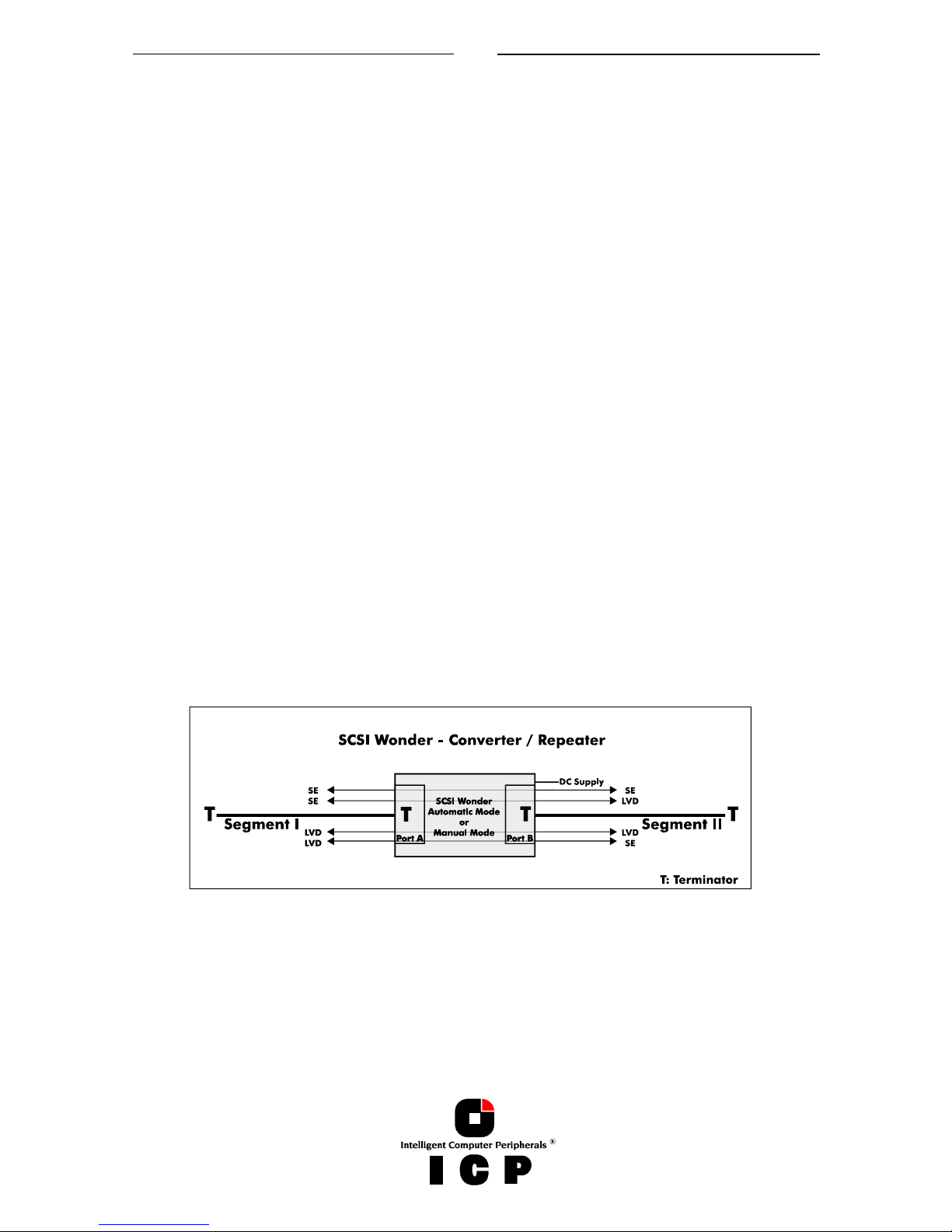
A.4.1 SCSI Wonder
SCSI Wonder is a very powerful and universal add-on for SCSI bus systems. It was developed with a special focus on Cluster Systems with parallel SCSI busses, but may also be
used for totally different tasks (also in combination with SCSI RAID Controllers or SCSI
Host Adapters of other vendors). SCSI Wonder allows a fully transparent connection between two SCSI bus segments. Both segments can be based on different transfer technologies (SE or LVD). SCSI Wonder does not require a SCSI ID on the SCSI bus and has no SCSI
bus protocol functions. SCSI Wonder is for both, the initiator (normally the SCSI RAID Controller) and the targets (the hard disks, CDROMs, DLTs, DATs, etc.) „invisible“.
SCSI Wonder can take over the following tasks:
Extension of an existing SCSI bus segment (up to 3 SCSI Wonder
can be used on one SCSI bus):
Connection of two LVD SCSI bus segments (LVD <-> LVD)
Connection of two SE SCSI bus segments (SE <-> SE)
Conversion of a SE SCSI bus segment into an LVD SCSI bus segment
and vice versa (SE <-> LVD; LVD <-> SE)
Installation of T-connections (stubs)
17
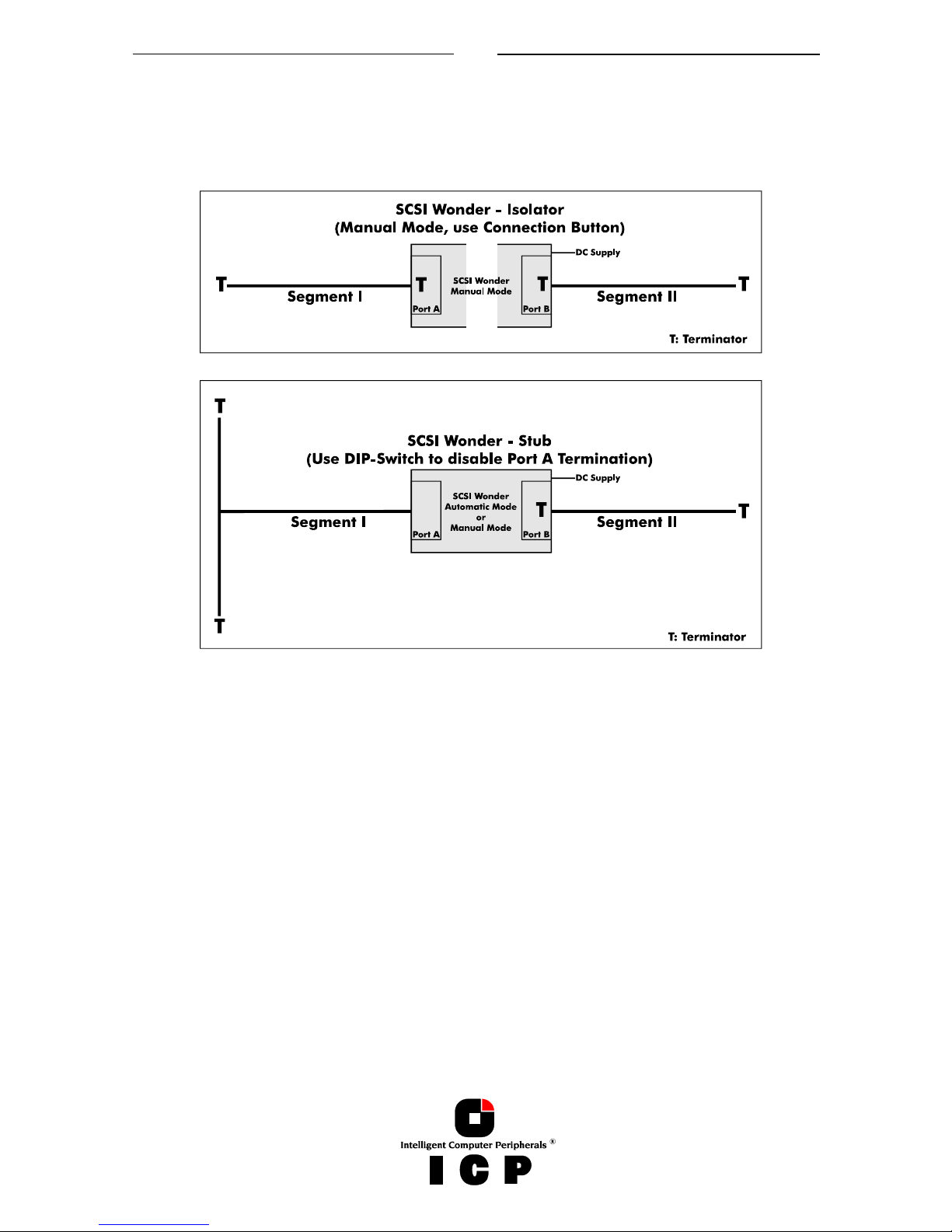
Isolation of two SCSI bus segments:
This brings a lot of security for Cluster Systems; SCSI bus segments can be separated or
reconnected without any detrimental effects for the SCSI bus (i.e., the other vital Server
node).
SCSI Wonder as an Isolator fulfills two primary tasks. First, it maintains a proper termination of the shared SCSI bus, even if one Node is removed. Second, it keeps the SCSI
bus signal quality on all remaining segments on an extremely good and healthy level.
18
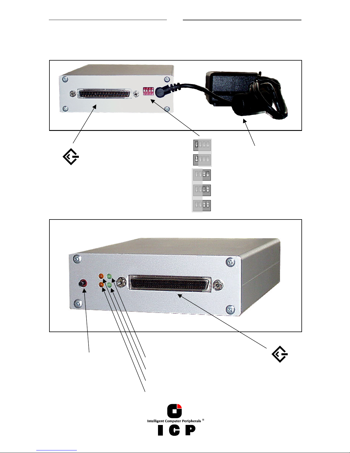
A.4.2 SCSI Wonder Overview
(Note: This description is also printed on the bottom of the SCSI Wonder enclosure.)
I
CP vortex Power Supply.
5
V/4A DC.
Use only the original ICP
vortex part !
Automatic Mode (Factory Setting)
All DIP-Switches down.
Manual Mode (use Connection Button)
Port A: Termination ON
P
ort B: Termination OF
F
P
ort A: Termination OF
F
Port B: Termination ON
P
ort A: Termination OF
F
P
ort B: Termination OF
F
P
ort B - SE/LVD
P
ort A - SE/LVD
Termpower Port B (ON=Termpower available)
Termpower Port A (ON=Termpower available
S
CSI Bus Activit
y
I
solation Mode (OFF=Ports A and B connected)
Connection Button (only in Manual
M
ode available).
P
ress once: Ports A and B isolated.
P
ress once again: Ports A and B
connected again.

19
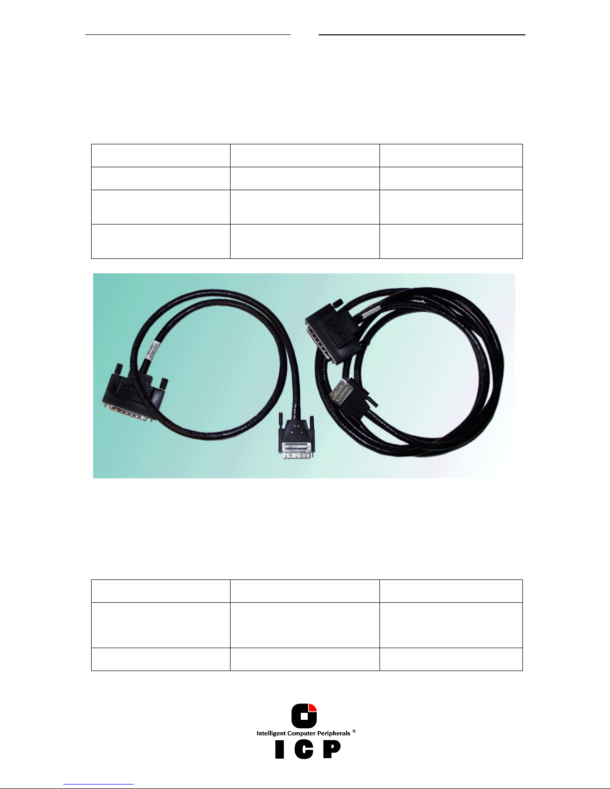
A.4.3 Cables, Terminators, Brackets
For the configuration of stable, high performance SCSI-Systems, we highly recommend you
to use genuine ICP vortex accessories.
Order # Part Name Description Application
8839 Wide/Ultra2 &
Ultra 160 Flat
Ribbon Cable
150 cm Wide/Ultra2 & Ultra 160 SCSI
cable with seven 68 pin HD SCSI connectors (male).
Connection of up to 5 internal
Wide/Ultra SCSI devices per SCSI
channel and one SE/LVD terminator
(Order No.: 8951).
For LVDS operation.
8844 Wide/Ultra2 &
Ultra 160
Round Cable
3 meters Wide/Ultra2 & Ultra 160 Round
Cable with stackable 68 pin VHD SCSI
connector (male) and 68 pin HD SCSI
connector (male). Both with thumb screws.
Connection of an external
Wide/Ultra2 & Ultra 160 SCSI subsystem.
For LVDS operation.
8877 Wide/Ultra2 &
Ultra 160
Round Cable
1 meter Wide/Ultra2 & Ultra 160 Round
Cable with stackable 68 pin VHD SCSI
connector (male) and 68 pin HD SCSI
connector (male). Both with thumb screws.
Connection of an external
Wide/Ultra2 & Ultra 160 SCSI subsystem. For LVDS operation.
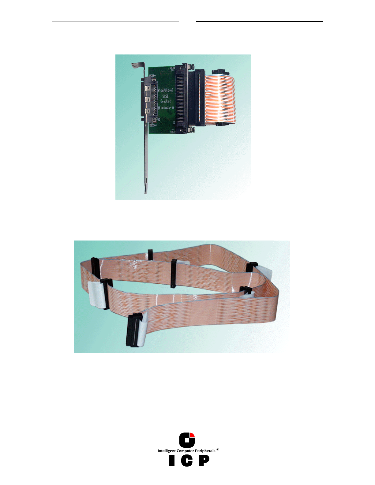
8845 Wide/Ultra2 &
Ultra 160
SCSI Bracket
Bracket with two internal 68 pin HD SCSI
connector (female) and two external 68
pin VHD SCSI connectors (female).
Connection of external Wide/Ultra2
& Ultra 160 SCSI subsystems. For
LVDS operation.
8849 Wide/Ultra2 &
Ultra 160
SCSI Bracket
Bracket with one internal 68 pin HD SCSI
connector (female) and one external 68
pin VHD SCSI connector (female).
Connection of an external
Wide/Ultra2 & Ultra 160 SCSI subsystem. For LVDS operation.
8850 Wide/Ultra2 &
Ultra 160 SCSI
Bracket
Bracket with one internal 68 pin HD SCSI
connector (female) and one external 68
pin HD SCSI connector (female).
Connection of an external
Wide/Ultra2 & Ultra 160 SCSI subsystem. For LVDS operation.
8880 Wide/Ultra2 &
Ultra 160
Round Cable
1 meter Wide/Ultra2 & Ultra 160 Round
Cable with 68 pin HD SCSI connectors
(male). Both with thumb screws.
Connection of an external
Wide/Ultra2 & Ultra 160 SCSI subsystem. For LVDS operation.
8951 LVDS/SE Ter-
minator
Terminator for LVDS or SE buses with 68
pin HD SCSI connector (female). LEDs
indicate, whether the bus/terminator is
operating in SE or LVDS mode.
Termination of SE or LVDS 68 pin
cables.
For LVDS operation.
8952 LVDS/SE Ter-
minator for
SE/LVDS Hard
Disks with SCA
Connector.
Terminator for LVDS or SE buses with SCA
connector for the hard disk and 68 pin
HD SCSI connector (female). Connector
for DC. Jumpers for SCSI-ID, Termination,
Termpower, etc.
This product converts Wide/Ultra2 &
Ultra 160 or Wide/Ultra hard disks
with SCA connector into "normal"
hard disks with termination (SE and
LVDS), DC connector, Jumpers for
SCSI-ID, etc..
For LVDS operation.
8953 External
LVDS/SE Terminator
Stackable external Terminator for SE or
LVD busses with 68 pin VHD SCSI connector (male). Thumb-Screws.
For LVDS operation.
20
4.4.4 SCSI Wonder to set up Cluster-Systems
For the configuration of stable, high performance Cluster-Systems, we highly recommend
you to use genuine ICP vortex accessories.
Equipment list per shared SCSI channel (from the controllers to the shared disk enclosure).
ICP vortex Part-Number Description Number
8954 SCSI Wonder incl. Power
supply
2
8844 or 8877 1 Meter / 3 Meter
from the controller to SCSI
Wonder
2
8844, 8877 or 8880 1 Meter / 3 Meter
from SCSI Wonder to the
shared disk enclosure
2
(8844, 8877. 1 Meters, 3 Meters external Wide/Ultra2 SCSI cables)
Additional equipment list per shared SCSI channel for the cabling inside the shared
disk enclosure (if necessary).
ICP vortex Part-Number Description Number
8849 Wide/Ultra2 SCSI Bracket
VHD<->HD
IN-and OUT connectors for
the subsystem
2
8839 Internal Wide/Ultra2 flat rib-
bon cable for 5 hard disks
1
21
(8849. Wide/Ultra2, Ultra 160 SCSI Bracket)
(8839. Wide/Ultra2, Ultra 160 SCSI flat ribbon cable)
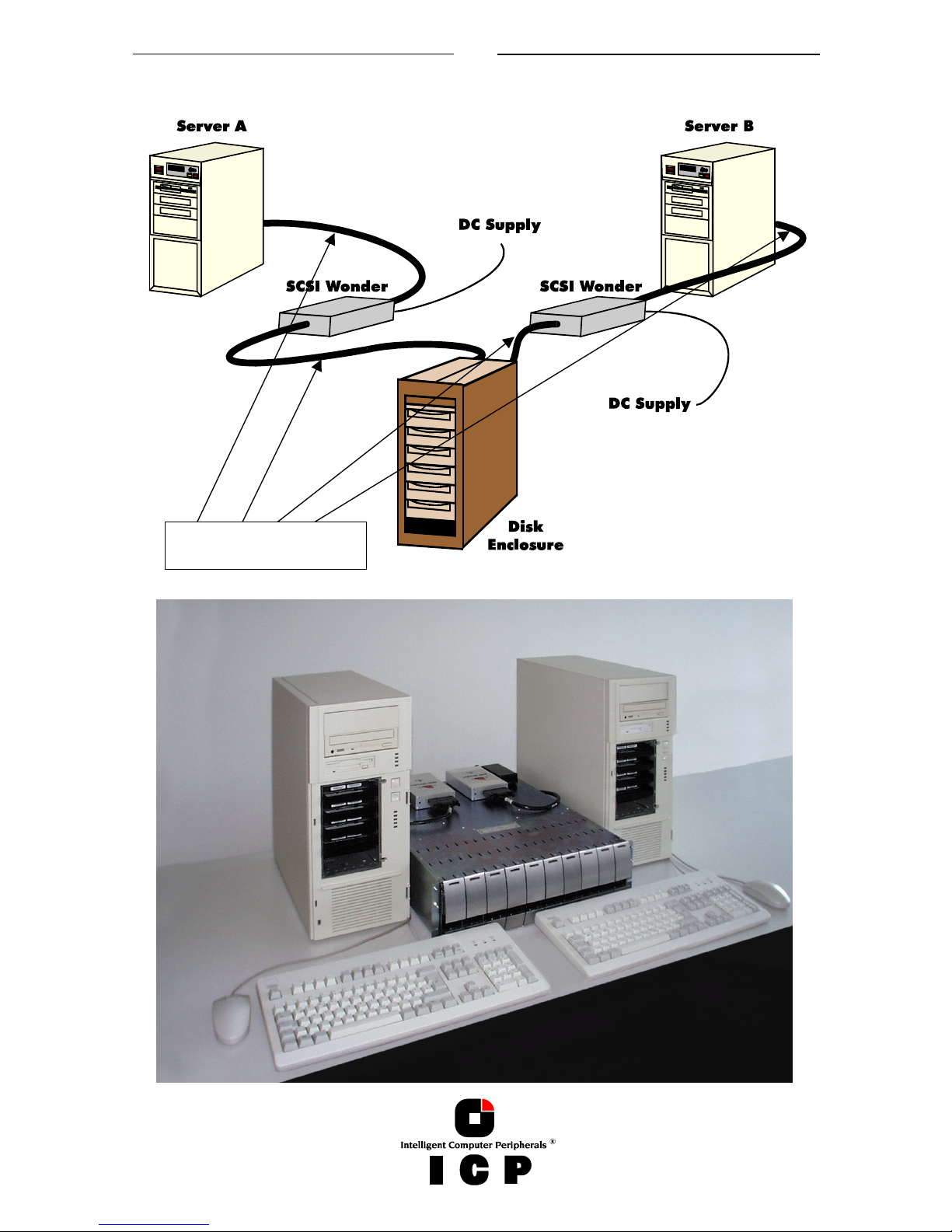
22
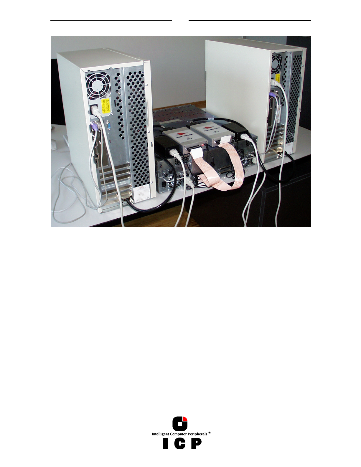
Typical Cluster Configuration:
8844/8877/8880
SCSI Cable
23
A.5 ICP vortex Accessories for Fibre Channel Controllers
A.5.1 ICP Fibre Hub 1016
Different to other solutions, the ICP Fibre Hub 1016 is designed not only for typical configurations which require a hub, but also for mission critical SAN and Clustering applications.
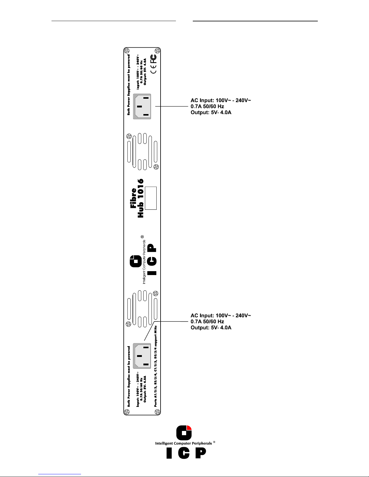
The 19” enclosure hosts two fully independent Hub Modules and two fully independent power
supplies. Each Hub Module contains two loops with 4 ports per loop. With ICP Fibre Hub
1016 in a Dual Loop setup not only the loops are redundant, but also the hubs and power
supplies.
The ICP Fibre Hub 1016 is able to connect up to 16 FC-AL devices in a physical star,
while keeping the devices in a logical ring configuration.
Connections to the hub use DB-9 connectors. Non-operating devices are automatically bypassed and newly communicating devices are automatically entered onto the loop. Full
Duplex operation per port with 1.0625 Gbit/sec. Repeater function per Port.
The ICP Fibre Hub 1016 can be symmetrically divided into 2, 3 or 4 separate loops with 4 ports
in each loop by using configuration switches.
12 of the 16 ports support the use of external Media Interface Adapters (MIAs)
24
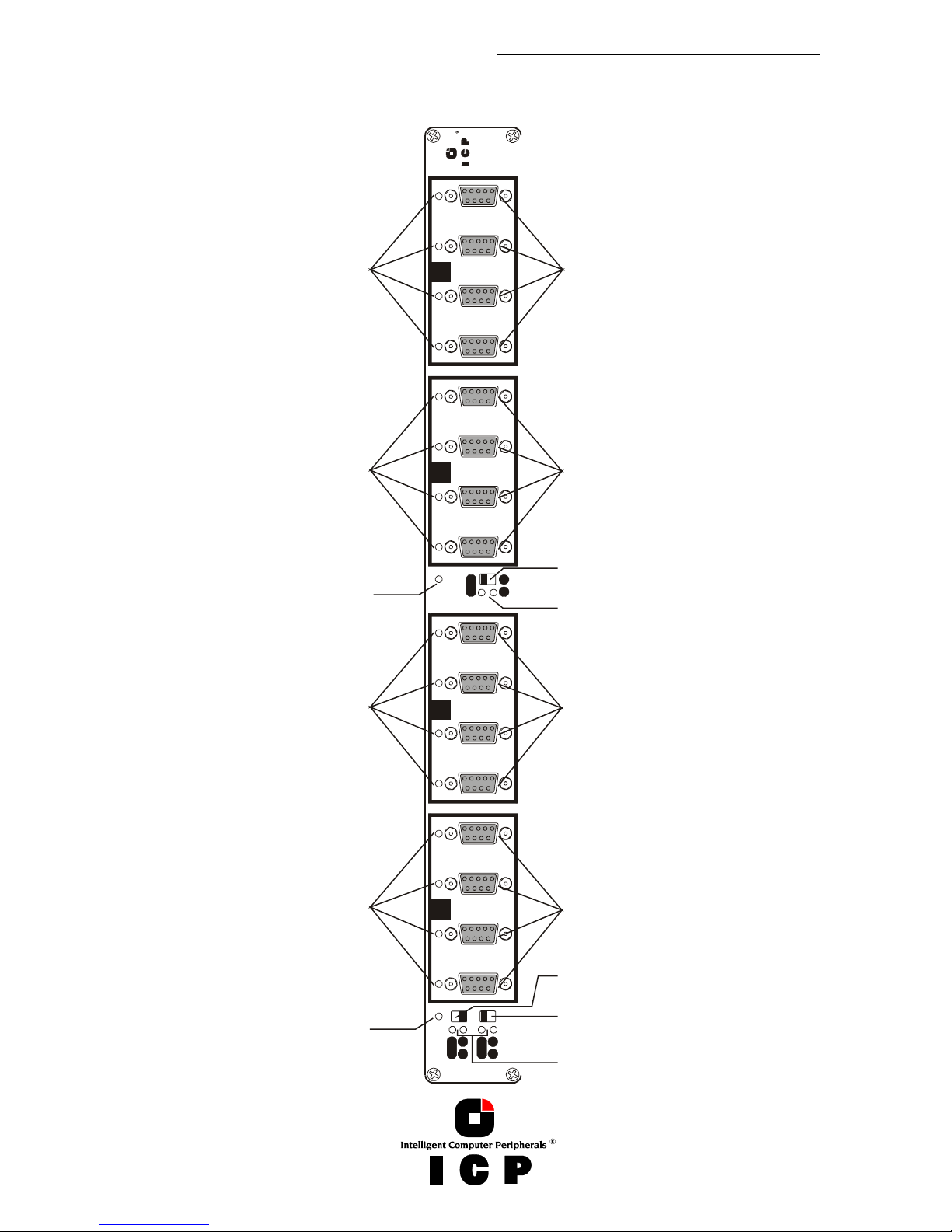
ICP Fibre Hub 1016 – Front View
A
12 3 4
B
12 3 4
C
12 3 4
D
12 3 4
Power
Powe r
B C
A BABB C
C D
C D
Intelligent Computer Peripherals
Fibre
Hub 1016
Configuration Switch
Loops C and D
Configuration Switch LEDs
Configuration Switch LEDs
"Power Good"
LED for Hub Module
Loops C and D
FC-AL Active LEDs
FC-AL Active LEDs
FC-AL Active LEDs
FC-AL Active LEDs
"Power Good"
LED for Hub Module
Loops A and B
Configuration Switch
Loops B and C
Configuration Switch
Loops A and B
FC-AL DB9 connectors
FC-AL DB9 connectors
FC-AL DB9 connectors
FC-AL DB9 connectors
25
ICP Fibre Hub 1016 – Rear View
26
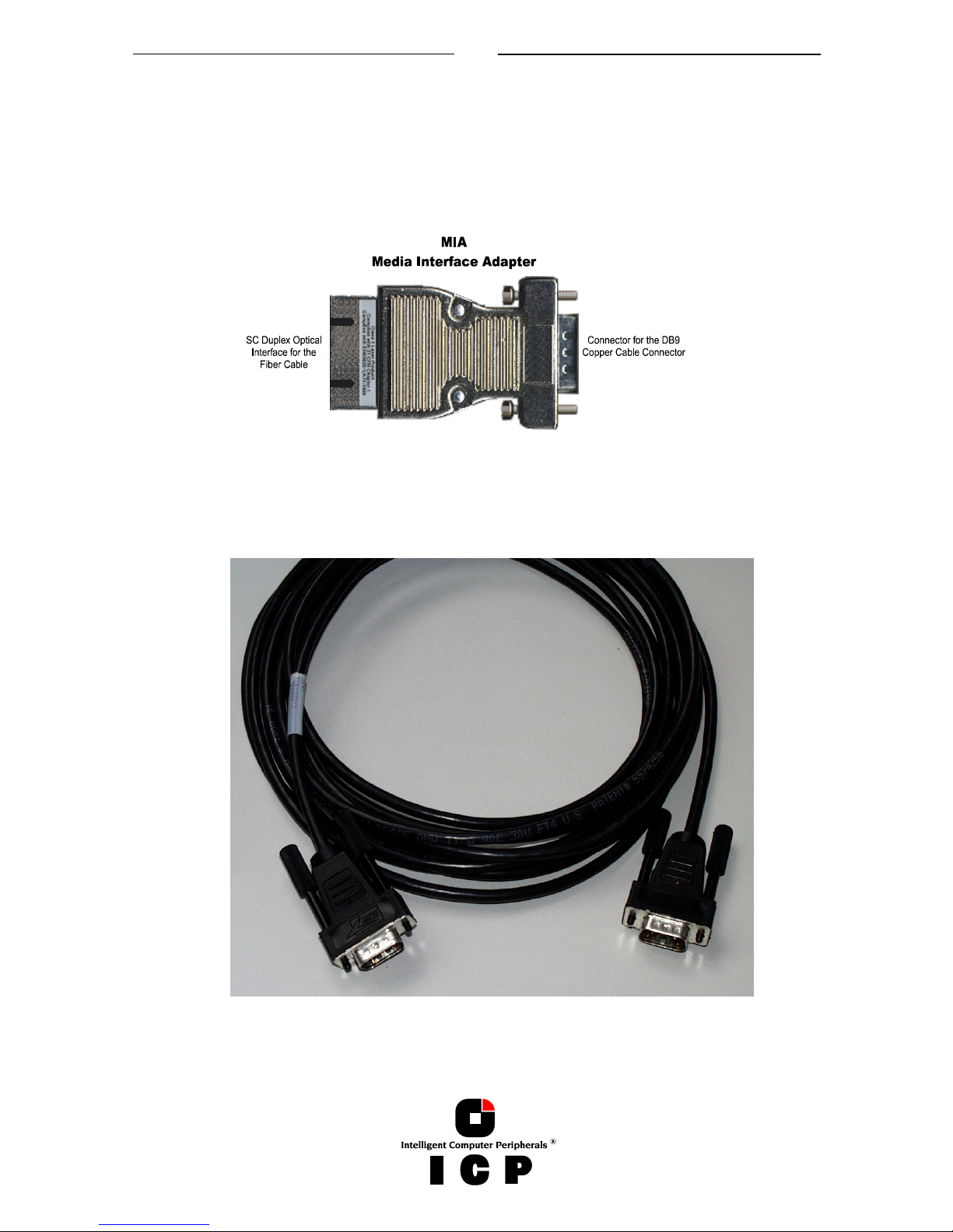
A.5.2 ICP vortex Fibre Channel Cables and MIAs
MIA adapters transform the electrical signals used by copper cables into optical signals
transmitted by optical fibers. One end of the adapter has an FC DB 9 male connector and
the other end has an SC duplex female connector for the optical fiber.
The adapter uses a laser diode to transform electrical signals into light signals and an opti-
cal sensor to perform the reverse function. 12 of the 16 ports of the ICP Fibre Hub 1016
support MIAs.
3 Meters Fibre Channel Copper Cable.
27
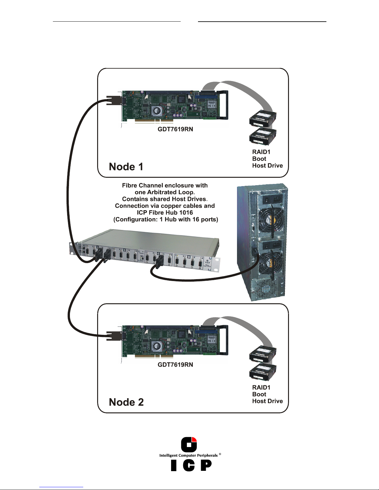
A.5.3 Sample Configurations
Clustering with one FC-AL; ICP Fibre Hub 1016 configured as one Hub with 16 ports
28
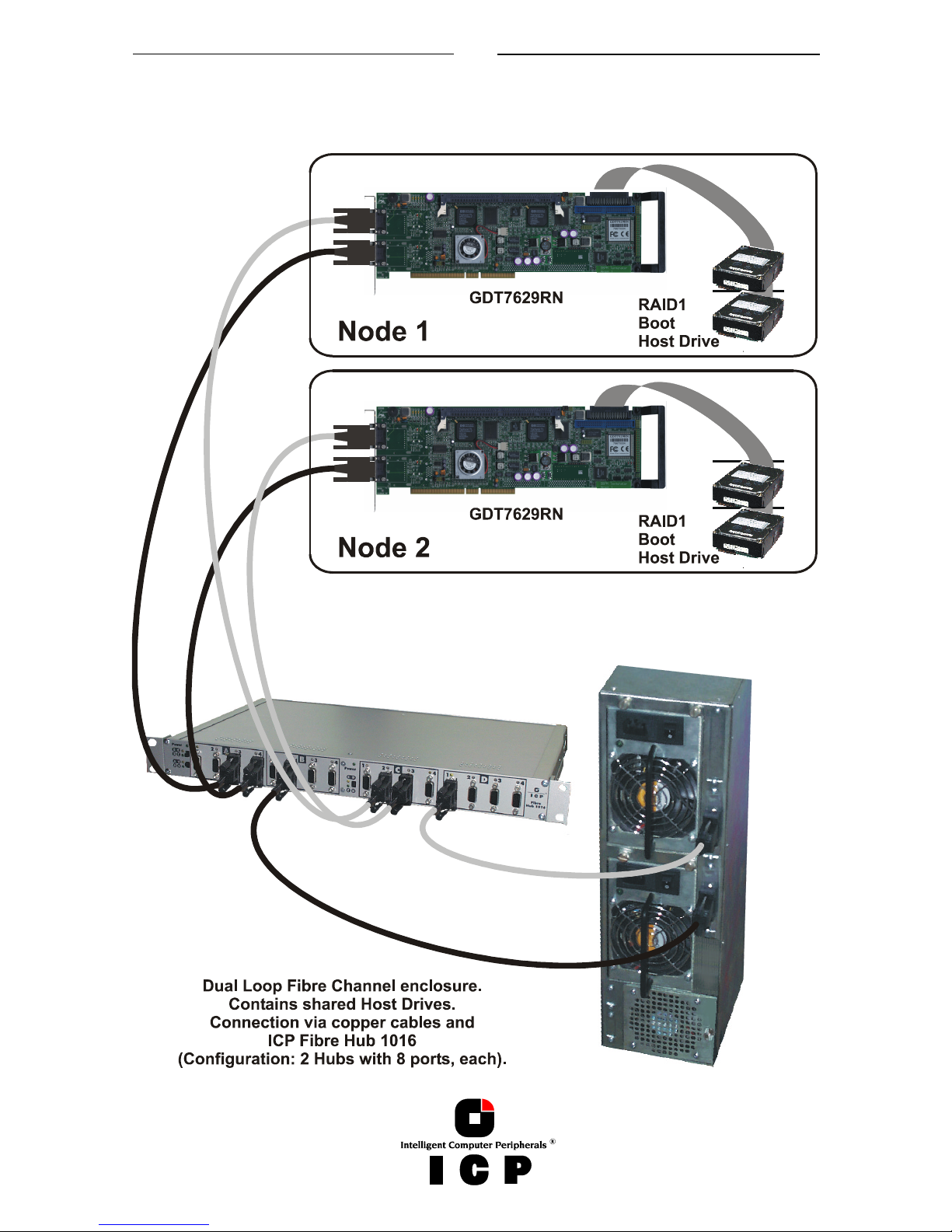
Clustering with Dual Loop FC-AL; ICP Fibre Hub 1016 configured as two independent Hubs
with 8 ports, each. Note: In this configuration Fibre Hub 1016 is split into two fully independent Hub Modules, each with a separate power supply.

29
Chapter B
IIIInnnnstallation Notes
stallation Notesstallation Notes
stallation Notes
30
B. Installation Notes
B.1 Hardware Installation
Wide/Ultra2 SCSI or Ultra 160 SCSI channels which are used as a shared I/O bus require per
shared channel 2 SCSI Wonders to make sure that the shared channel continues to work
even if a server is switched off, or if the bus is separated from the ICP Controller in one of
the servers.
For the configuration of Cluster Systems with ICP Fibre Channel Controllers, it is recommended to use the ICP Fibre Hub 1016, which ensures that the loop is always closed even if
one Controller fails, or if the fibre channel cable is removed. ICP Controllers with two independent loops allow the set up of a dual loop configuration. In such a configuration, there
is not only redundancy at server level but also at I/O channel level: One loop can fail and
the system continues to run on the other loop. ICP Fibre Hub 1016 was specifically designed for such dual loop configurations (it consists of two independent Hub Modules and
two independent power supplies).
B.2 Using Wide/Ultra2 and Ultra 160 SCSI ICP Controllers
Both ICP Controllers for the two nodes should be identical (same model, same firmware
level).
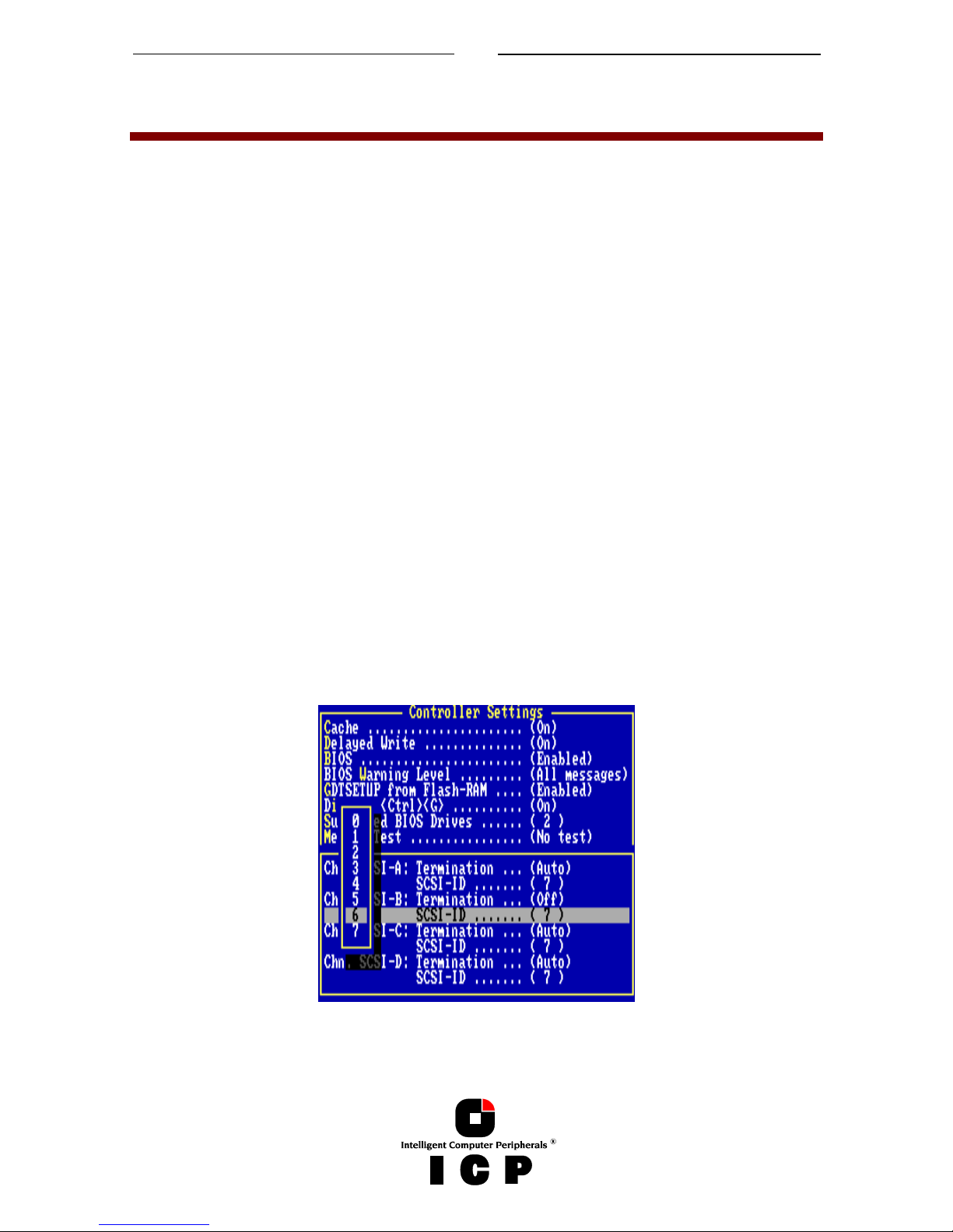
Before connecting both controllers to the shared I/O cable, one of the IOPs (Input/Output
Processor) on one of the controllers must be set to another ID e.g., ID6). This has to be
done for all I/O channels which are used as Clustering channels. The easiest way to change
the IOP IDs is to use ICPCON (ICP RAID Console) loaded with <CTRL>+<G> from the controller's ROM.
 Loading...