

ICP GDT6518RS, GDT RN Series, GDT6118RS, GDT6128RS, GDT6528RS User Manual
...
1
User's Manual
ICP Controllers of the GDT RS and RN Series
32-Bit / 64-Bit PCI
Ultra2 SCSI and Ultra 160 SCSI
RAID Controllers
1st Edition
© Copyright 1998-2000
ICP vortex Computersysteme GmbH
Konrad-Zuse-Str. 9
74172 Neckarsulm - Germany
ICP vortex Corporation
4001 E. Broadway / B-20
Phoenix, AZ 85040, USA
All Rights and Changes Reserved.
01

2

3
Contents - Overview
Contents - OverviewContents - Overview
Contents - Overview
Part I
Part IPart I
Part I
Chapter A General Information
Chapter B Hardware Installation
Chapter C Quick-Setup
Part II
Part IIPart II
Part II
Chapter D Using Microsoft MS-DOS,
Windows 95/98
Chapter E Using Novell NetWare
Chapter F Using Windows NT/2000
Chapter G Using LINUX
Chapter H Using SCO UNIX
Chapter I Using UnixWare
Part III
Part IIIPart III
Part III
Chapter J The ICP RAID Console
Chapter K The ICP RAID Navigator
Chapter L Appendix

4
Limited Warranty
Limited WarrantyLimited Warranty
Limited Warranty
ICP vortex Corporation ("ICP vortex") guarantees that this product is free from defects in material
and workmanship. Subject to the conditions and limitations set forth below, ICP vortex will, at its
own option, either repair or replace any part of this product which proves to be defective by reasons
of improper workmanship or materials. Parts used to repair products or replacement products will
be provided by ICP vortex on an exchange basis, and will be either new or refurbished to be functionally equivalent to new.
This warranty does not cover any damage to this product, which results from accident, abuse, misuse, natural or personal disaster, Acts of God, or any unauthorized disassembly, repair or modification. The duration of this warranty is one year from the date of original retail purchase.
Warranty Claim Requirements
Warranty Claim RequirementsWarranty Claim Requirements
Warranty Claim Requirements
To obtain warranty service, return the defective product, freight prepaid and insured, to your local
authorized ICP vortex dealer or distributor, or to ICP vortex Corporation, 4001 E. Broadway, B-20,
Phoenix, AZ 85040. Please note the following: You must include the product serial number, and a
detailed description of the problem you are experiencing. You must also include proof of the date of
original retail purchase as evidence that the product is within the warranty period.
If you need to return the product to ICP vortex, you must first obtain a Return Material Authorization
(RMA) number by calling ICP vortex Corporation at 602-414-0414. This RMA number must be displayed on the outside of your package. Products must be properly packaged to prevent damage in
transit. ICP vortex accepts no responsibility for products which are damaged on arrival due to poor
freight service.
Disclaimers
DisclaimersDisclaimers
Disclaimers
The foregoing is the complete warranty for ICP vortex products and supersedes all other warranties
and representations, whether written or oral. Except as expressly set forth above, no other warranties
are made with respect to ICP vortex products. ICP vortex expressly disclaims all warranties not stated
herein, including, to the extent permitted by applicable law, any implied warranty of merchantability
or fitness for a particular purpose. In no event will ICP vortex be liable to the purchaser, or to any
user of the ICP vortex product, for any data loss, data corruption, damages, expenses, lost revenues, lost savings, lost profits, or any other incidental or consequential damages arising from the
purchase, use or inability to use the ICP vortex product, even if ICP vortex has been advised of the
possibility of such damages.
ICP vortex is not liable for, and does not cover under warranty, any costs associated with servicing
and/or installation of ICP vortex products.
This manual has been validated and reviewed for accuracy. The sets of instructions and descriptions were accurate for ICP Disk Array Controllers at the time of this manual’s production. However, succeeding Controllers, software and manuals are subject to change without notification.
Therefore, ICP vortex assumes no liability for damages incurred directly or indirectly from errors,
omissions or discrepancies between the Controller, software and the manual.
5
Pick up the phone
if you need technical support
and dial the numbers:
For Europe: +49-(0)7132-9620-900
For the USA: 602-414-0414
or send us a FAX:
For Europe:
+49-(0)7132-9620-400
For the USA: 602-414-0444
or send us an E-Mail:
For Europe: support@vortex.de
For the USA: support@icp-vortex.com
or check our Website:
http://www.icp-vortex.com
6
Important Note
Using modern RAID Systems significantly increases data security and availability. Under no
circumstances does it relieve you from a careful and daily backup on tape or a similar backup
media. This is the only method to protect your valuable data against total loss (e.g.,
through fire or theft), accidental deletion, or any other destroying impacts.
Many Thanks to all my Friends
Monika & Wolfgang (the grandmasters)
AnnDee, Lois, Jeniffer, Valerie, Carl, Frank, Ken (the right one) and William (the Phoenix Crew)
Achim, Dieter, Günter, Hooshiar, Johannes, Jörg, Norbert, Otto, Ralph, Sam, Steffen, Winfried
Brigitte, Alfred (AB, "We need clustering. I say we have it") and Ruediger
Andreas (AK, or "Kopf nur mit ö")
Michael (Mipf, "where is my CPU ?")
Jürgen (Jogo, "Hi, is Jurgen there ?")
Jürgen (JB, "diesbezüglich & hinsichtlich or probably")
Markus (Malu, "Luuuuu...."), Uwe, Ralf
All the fantastic "rest" of this incredible company.
It is not only a pleasure to work here, it is a passion.

7
FCC Compliance
FCC ComplianceFCC Compliance
FCC Compliance Statement
Statement Statement
Statement
Information for the User
NOTE: This equipment has been tested and found to comply with the limits for a Class B
digital device, pursuant to Part 15 of the FCC Rules. These limits are designed to provide
reasonable protection against harmful interference in residential installations. This equipment generates, uses, and can radiate radio frequency energy, and if not installed and used
in accordance with the instructions, may cause harmful interference to radio communications. However, there is no guarantee that interference will not occur in a particular installation. If this equipment does cause harmful interference to radio or television reception,
which can be determined by turning the equipment off and on, the user is encouraged to
try to correct the interference by one or more of the following measures:
- Reorientate or relocate the receiving antenna.
- Increase the separation between the equipment and the receiver.
- Plug the equipment into an outlet on a circuit different from that to which the receiver is
powered.
- If necessary, consult the dealer or an experienced radio/T.V. technician for additional
suggestions.
The use of a non-shielded interface cable with the referenced device is prohibited.
Changes or modifications not expressly approved by ICP vortex Computersysteme GmbH
could void the authority to operate the equipment.

8
Table of Contents
A. Introduction..................................................................................................................................................16
A.1 Product Identification .............................................................................................................................16
A.1.1 Key Features of the ICP Controllers of the GDT RS and RN Series...........................................................17
A.2 Copyrights, Patents ................................................................................................................................19
A.3 Software License Agreement....................................................................................................................20
A.4 General Information...............................................................................................................................21
A.4.1 Unpacking the ICP Controller.............................................................................................................21
A.4.2 Delivery Contents.............................................................................................................................21
A.4.3 Contents of the ICP CDROM...............................................................................................................21
A.4.4 Before You Start ..............................................................................................................................21
A.5 Product Description ................................................................................................................................22
A.5.1 Intel i960RS or i960RN I/O Processor...............................................................................................22
A.5.2 64 Bit Architecture...........................................................................................................................22
A.5.3 Cache RAM - Expandable to 128MB ..................................................................................................22
A.5.4 Compatibility - PCI...........................................................................................................................22
A.5.5 Up to 6 Ultra 160 SCSI Channel........................................................................................................22
A.5.6 ICP Controller Firmware, BIOS and ICP RAID Console...........................................................................22
A.5.7 Configuration and Monitoring utilities “ICP RAID Console” and “ICP RAID Navigator” Program ICPCON....23
A.5.8 Operating System Driver Software .....................................................................................................25
A.5.9 ICP Controller Board Layout .............................................................................................................25
B. Hardware Installation....................................................................................................................................36
B.1 Before Installation.................................................................................................................................36
B.2 Tools....................................................................................................................................................36
B.3 Installing the PC100 DIMM Module.........................................................................................................36
B.4 SCSI - Basics..........................................................................................................................................37
B.4.1 SCSI Cables.....................................................................................................................................38
B.4.2 SCSI Termination.............................................................................................................................43
B.4.3 SCSI ID...........................................................................................................................................43
B.4.4 ICP SCSI Accessories.........................................................................................................................44
B.4.5 Examples........................................................................................................................................46
B.6 ICP Controller Function Check..................................................................................................................49
B.6.1 PCI 2.2 Compatibility Requirements .................................................................................................49
B.6.1 Trouble Shooting.............................................................................................................................51
B.6.2 Checking the ICP Controller Configuration...........................................................................................51

9
C. Quick-Setup .................................................................................................................................................54
C.1 What is the Aim of Quick-Setup ?.........................................................................................................54
C.2 What is the ICP Controller Firmware ? ......................................................................................................54
C.2.1 The Different RAID Levels..................................................................................................................56
C.2.2 Levels of Hierarchy Within the ICP Firmware.......................................................................................59
C.2.3 Using CD-ROMs, DATs, Tapes, etc......................................................................................................60
C.3 Example 1 - Installing a Single SCSI Hard Disk.........................................................................................60
C.4 Example 2 - Installing a Mirroring Array - RAID 1 .....................................................................................62
C.5 Example 3 - Installing a RAID 5 Disk Array...............................................................................................63
C.6 Trying to Answer The Initial Questions......................................................................................................65
C.6.1 How Many Hard Disks Should be Integrated Into the Disk Array ?.........................................................65
C.6.2 Which Level of Redundancy is Needed ?.............................................................................................66
C.6.3 Do we Need Hot Fix drives ?..............................................................................................................66
C.7 States of a RAIDYNE® Disk Array ...........................................................................................................67
C.7.1 "Idle" State.....................................................................................................................................67
C.7.2 "Build" State...................................................................................................................................67
C.7.3 "Ready" State..................................................................................................................................67
C.7.4 "Fail" State .....................................................................................................................................67
C.7.5 "Rebuild" State................................................................................................................................67
C.7.6 "Expand" State................................................................................................................................67
C.7.7 "Error" State....................................................................................................................................67
C.8 Methods for the Replacement of a Disk Drive ............................................................................................69
D. Using Microsoft MS-DOS ...............................................................................................................................72
D.1 Transparency of Host Drives....................................................................................................................72
D.2 Partitioning a Host Drive and Transferring MS-DOS...................................................................................72
D.3 CONFIG.SYS and the Driver GDTX000.EXE ................................................................................................72
D.4 Expanded Memory Managers..................................................................................................................73
D.5 Using a CDROM Drive under MS-DOS ......................................................................................................74
D.5.1 Example: Using the ASW Software for the CDROM ..............................................................................75
D.5.2 Example: Using corelSCSI for the CDROM...........................................................................................75
D.6 The ICP ASPI Manager GDTASPI.EXE........................................................................................................76
D.6.1 Using ASW ASPIDISK.SYS ................................................................................................................77
D.6.2 Using corelSCSI...............................................................................................................................77
D.7 Installing Windows 95 ...........................................................................................................................78
D.7.1 The ICP Controller is the primary controller.........................................................................................78
D.7.2 The ICP Controller is the secondary controller......................................................................................79
D.7.3 Update the ICP Windows 95 Driver....................................................................................................79

10
D.8 Installing Windows 98 ...........................................................................................................................80
E. Using Novell NetWare ...................................................................................................................................82
E.1 Transparency of Host Drives ....................................................................................................................82
E.2 Novell NetWare 3.10, 3.1, 3.12 and 3.20...............................................................................................82
E.3 Novell NetWare 4.x – Using "DSK" Driver ................................................................................................82
E.4 Novell NetWare 4.x/5.x – Using "HAM" Driver.........................................................................................83
E.5 Tips and Tricks.......................................................................................................................................85
E.5.1 Optimize Data Throughput................................................................................................................85
E.5.2 'cache memory allocator out of available memory' in PCI-ISA Systems..................................................85
E.5.3 Installing NetWare 4.1 - Wrong Drive Name ......................................................................................86
E.5.4 NetWare-Server Not Stable When High Utilization ..............................................................................86
E.5.5 ICP Controller and Non-ASPI Compatible Controllers............................................................................86
E.5.6 Last Status Information ....................................................................................................................87
E.5.7 Adding Additional Capacity After An Online Capacity Expansion ............................................................87
E.6 Notes on ARCserve .................................................................................................................................87
F. Using Microsoft Windows NT or Windows 2000................................................................................................90
F.1 Transparency of Host Drives ....................................................................................................................90
F.2 Windows NT ..........................................................................................................................................90
F.2.1 Preparing the Installation .................................................................................................................90
F.2.2 The Installation................................................................................................................................92
F.2.2.1 The ICP Controller is the first Controller in the System .......................................................................92
F.2.2.2 The ICP Controller is the Secondary Controller in the System..............................................................92
F.2.3 Using the Hot Plug Function with RAID Host Drives .............................................................................93
F.2.4 Installation of a new GDTX.SYS Driver Version.....................................................................................93
F.2.5 Installation of a Removable Hard Disk ...............................................................................................93
F.2.6 Adding Additional Capacity After An Online Capacity Expansion ............................................................94
F.2.7 Update Windows NT -> Windows 2000 ...........................................................................................94
F.3 Windows 2000......................................................................................................................................94
F.3.1 Preparing the Installation .................................................................................................................94
F.3.2.1 The ICP Controller is the first Controller in the System .......................................................................95
F.3.2.2 The ICP Controller is the second Controller in the System...................................................................95
G. Using LINUX.................................................................................................................................................98
G.1 Transparency of Host Drives ....................................................................................................................98
G.2 Available Drivers and Tools.....................................................................................................................98
G.3 Updating the driver using the driver sources .............................................................................................98
G.4 Driver installation or update using a patch ...............................................................................................98
G.5 ICPCON – Configuration and Monitoring Tool ...........................................................................................99

11
G.6 gdth driver parameters.........................................................................................................................100
G.7 Notes .................................................................................................................................................101
H. Using SCO UNIX V/386...............................................................................................................................104
H.1 Transparency of Host Drives..................................................................................................................104
H.2 General Tips for Installation..................................................................................................................104
H.3 Instructions on mkdev (ADM) for 3.2v4.x...............................................................................................105
H.4 Instructions on mkdev (ADM) for 3.2v5.x (Open Server)..........................................................................108
H.5 Further Information .............................................................................................................................109
I. Using UnixWare...........................................................................................................................................112
I.1 Transparency of Host Drives...................................................................................................................112
I.2 General Installation Notes .....................................................................................................................112
I.3 ICP Controller as Boot Controller.............................................................................................................112
I.4 ICP Controller as an additional Controller ................................................................................................113
I.5 Coordinates of SCSI devices ...................................................................................................................113
I.6 Further Information...............................................................................................................................114
J. The Program ICPCON ...................................................................................................................................116
J.1 Loading ICPCON...................................................................................................................................116
J.1.1 Loading the ICPCON Program Under NetWare ...................................................................................116
J.1.2 Loading the ICPCON Program Under Solaris 7...................................................................................117
J.1.3 Loading the ICPCON Program Under Windows NT / 2000...................................................................117
J.1.4 Loading the ICPCON Program Under Windows 95/98 ........................................................................117
J.1.5 Loading ICPCON Under SCO UNIX ....................................................................................................117
J.1.6 Loading ICPCON Under LINUX .........................................................................................................118
J.2 The ICPCON Program ............................................................................................................................118
J.2.1 Select Interface ..............................................................................................................................119
J.2.2 Select Controller.............................................................................................................................120
J.2.3 The two Menu Areas "Monitor" and "Express/Advanced Setup"............................................................120
J.3 The Menu Monitor................................................................................................................................121
J.3.1 Menu Monitor: View Statistics..........................................................................................................121
J.3.2 Menu Monitor: View Events.............................................................................................................122
J.3.3 Menu Monitor: View Hard Disk Info..................................................................................................122
J.3.4 Menu Monitor: Save Information .....................................................................................................123
J.4 The Menu Express/Advanced Setup ........................................................................................................124
J.4.1 Menu Express Setup: Configure Host Drives.......................................................................................124
J.4.2 Menu Express Setup: Repair Array Drives ..........................................................................................128
J.4.3 Menu Advanced Setup: Configure Controller ......................................................................................130

12
J.4.3.1 Menu Advanced Setup: Configure Controller, Controller Settings................................................130
J.4.3.2 Menu Advanced Setup: Configure Controller, Firmware Update .................................................131
J.4.3.3 Menu Advanced Setup: Configure Controller, Intelligent Fault Bus.............................................131
J.4.3.4 Menu Advanced Setup: Conf. Controller, Non-Intelligent Enclosures...........................................131
J.4.3.5 Menu Advanced Setup: Configure Controller, Advanced Settings................................................133
J.4.3.6 Menu Advanced Setup: Configure Controller, Cluster Settings....................................................133
J.4.3.7 Menu Advanced Setup: Configure Controller, Clear Log Buffer ...................................................133
J.4.4 Menu Advanced Setup: Configure Physical Devices.............................................................................133
J.4.4.1 Menu Advanced Setup: Configure Phys. Devs., SCSI Parameter /Initialize ..................................135
J.4.4.2 Menu Advanced Setup: Configure Phys. Devs., Format Disk ......................................................136
J.4.4.3 Menu Advanced Setup: Configure Phys. Devs., Check Surface ...................................................136
J.4.4.4 Menu Advanced Setup: Configure Phys. Devs., View Status/Defects...........................................136
J.4.4.5 Menu Advanced Setup: Configure Phys. Devs., Deinitialize Disk ................................................136
J.4.4.6 Menu Advanced Setup: Configure Phys. Devs., Lock/Unlock Disk...............................................137
J.4.4.7 Menu Advanced Setup: Configure Phys. Devs., Enclosure Status................................................137
J.4.5 Menu Advanced Setup: Configure Logical Drives ................................................................................139
J.4.6 Menu Advanced Setup: Configure Array Drives...................................................................................140
J.4.6.1 Menu Advanced Setup: Configure Array Drives, Change Drive Name ..........................................141
J.4.6.2 Menu Advanced Setup: Configure Array Drives, Expand Array Drive ...........................................141
J.4.6.3 Menu Advanced Setup: Configure Array Drives, Add RAID 1 Component.....................................141
J.4.6.4 Menu Advanced Setup: Configure Array Drives, Replace Array Component..................................141
J.4.6.5 Menu Advanced Setup: Configure Array Drives, Remove RAID 1 Component...............................141
J.4.6.6 Menu Advanced Setup: Configure Array Drives, Remove Array Drive...........................................142
J.4.6.7 Menu Advanced Setup: Configure Array Drives, Add Hot Fix Drive..............................................142
J.4.6.8 Menu Advanced Setup: Configure Array Drives, Remove Hot Fix Drive........................................143
J.4.6.9 Menu Advanced Setup: Configure Array Drives, Hot Fix Pool Access ...........................................143
J.4.6.10 Menu Advanced Setup: Configure Array Drives, Parity Verify ...................................................143
J.4.6.11 Menu Advanced Setup: Configure Array Drives, Parity Recalculate...........................................143
J.4.6.12 Menu Advanced Setup: Configure Array Drives, Build/Rebuild Progress....................................143
J.4.6.13 Menu Advanced Setup: Configure Array Drives, Create new Array Drive ....................................144
J.4.7 Menu Advanced Setup: Configure Host Drives....................................................................................145
J.4.7.1 Menu Advanced Setup: Configure Host Drives, Change Drive Name ...........................................146
J.4.7.2 Menu Advanced Setup: Configure Host Drives, Swap Host Drives...............................................146
J.4.7.3 Menu Advanced Setup: Configure Host Drives, Remove Host Drives ...........................................146
J.4.7.4 Menu Advanced Setup: Configure Host Drives, Split Host Drive .................................................146
J.4.7.5 Menu Advanced Setup: Configure Host Drives, Merge Host Drives..............................................146
J.4.7.6 Menu Advanced Setup: Configure Host Drives, Partition Host Drives ..........................................146
J.4.7.7 Menu Advanced Setup: Configure Host Drives, Overwrite Master Boot Code................................146
J.4.7.8 Menu Advanced Setup: Configure Host Drives, Drive Type (Cluster)............................................146
K. ICP RAID Navigator .....................................................................................................................................148

13
K.1 Introduction ........................................................................................................................................148
K.2 The ICP RAID Navigator "Controls".........................................................................................................149
K.2.1 The Toolbar...................................................................................................................................149
K.2.2 The Status Bar...............................................................................................................................149
K.2.3 "Window" Menu Commands ...........................................................................................................149
K.2.4 "Help" Menu Commands ................................................................................................................150
K.2.5 "File" Menu Commands..................................................................................................................150
K.2.6 "View" Menu Commands ................................................................................................................150
K.2.7 The "Chart" Menu ..........................................................................................................................151
K.2.8 The "Configuration" Menu Commands..............................................................................................151
K.3 Select Controller...................................................................................................................................152
K.4 Physical Configuration Window..............................................................................................................152
K.4.1 Controllers.....................................................................................................................................153
K.4.2 I/O Processors ...............................................................................................................................155
K.4.3 Direct Access Devices......................................................................................................................156
K.4.4 Non direct access devices (raw devices)............................................................................................160
K.5 Logical Configuration Window...............................................................................................................161
K.5.1 The Host Drive Information Window.................................................................................................164
K.5.2 The Array Drive Information Window................................................................................................164
K.5.3 The Logical Drive Information Window.............................................................................................166
K.5.4 Change the name of a Drive............................................................................................................167
K.5.5 Remove a Host Drive......................................................................................................................167
K.5.6 Create a new Host Drive .................................................................................................................167
K.5.7 Parity Verify ..................................................................................................................................168
K.5.8 Parity Recalculate..........................................................................................................................168
K.5.9 Progress Information......................................................................................................................169
K.5.10 Expansion of an Array ..................................................................................................................169
K.5.11 Add a Hot Fix Drive......................................................................................................................170
K.5.12 Remove a Hot Fix Drive ................................................................................................................171
K.5.13 Hot Fix Pool Access ......................................................................................................................171
K.5.14 Add a RAID 1 Component (Mirror a Drive)......................................................................................171
K.5.15 Remove a RAID 1 Component (Remove a Mirror Drive)....................................................................172
K.5.16 Replace a Logical Drive ................................................................................................................172
K.5.17 The Different States of an Array Drive.............................................................................................172
K.6 The Statistics Window...........................................................................................................................175
K.7 The Controller Events Window ...............................................................................................................176
K.8 ICP RAID Navigator Help.......................................................................................................................177
K.9 ICP Service and ICP Mail.......................................................................................................................178
L. Appendix ....................................................................................................................................................184

14
L.1 Technical Data of the ICP Controller........................................................................................................184
L.2 Boot Error Messages.............................................................................................................................184
L.3 Index ..................................................................................................................................................185

15
Chapter A
General
GeneralGeneral
General
Information
InformationInformation
Information

16
A. Introduction
GDT RN Series: 64 Bit PCI hardware RAID Disk Array Controllers with up to 3
Wide/Ultra2 SCSI or up to 6 Ultra 160 SCSI channels
GDT RS Series: 32 Bit PCI hardware RAID Disk Array Controllers with up to 3
Wide/Ultra2 SCSI channels
In order to take full advantage of modern operating systems, high performance computer
systems are needed. When assessing the performance of a computer system, the aspects
speed and security of the mass-storage subsystem are gaining increasing importance. As a
result of the constantly growing acceptance of the RAID technology (Redundant Array of
Independent Disks) in these computer systems, and the identification of the RAID controller as the essential part of a disk subsystem, a strong demand for suitable RAID controllers
has emerged during the past few years.
Since 1990, ICP vortex has been intensively engaged in the research and development of
RAID products for the highest performance and security requirements. Due to our products’
outstanding performance, our expertise and continuity in development, ICP Controllers are
accepted and known as top leading-edge products all over the world. ICP Controller products within the GDT RS and RN Series are suitable for the most different platforms and applications. All ICP Controllers are pure-bred hardware solutions.
All functionality required for the very complex tasks is hardware-implemented on the controller. Thus, RAID is fully independent of the computer system (the host) and the operating system. Thanks to the wide operating system support and easy-to-use installation and
maintenance utilities, setting up and using high performance and fault-tolerant massstorage subsystems for almost every purpose is child’s play.
We would like to thank you for purchasing an ICP Controller.
ICP - Intelligent Computer Peripherals
®
A.1 Product Identification
In order to meet the various customer and system requirements, ICP vortex offers various
RS and RN Series Disk Array Controllers for 32 Bit and 64 Bit PCI computer systems. The
main differences between the controllers lie in PCI bus width, the number of Wide/Ultra2
and Ultra1 160 SCSI channels, the supported RAID levels and the Clustering Support. All
Wide/Ultra2 SCSI models of the RN Series feature an additional Wide/Ultra SCSI channel for
legacy SCSI devices.
GDT RS Series, 32-Bit PCI Bus (Controllers can be operated in a 32-Bit and 64-Bit PCI Bus)
ICP Controller
Name
Number of Wide/Ultra2 SCSI channels Supported RAID Levels
GDT6118RS 1 0/1
GDT6128RS 2 0/1
GDT6518RS 1 0/1/4/5/10
GDT6528RS 2 0/1/4/5/10
GDT6538RS 3 0/1/4/5/10
17
GDT RN Series, 64-Bit PCI Bus (Controllers can be operated in a 32-Bit and 64-Bit PCI Bus) with
Wide/Ultra2 SCSI channels
ICP Controller
Name
Number of Wide/Ultra2
SCSI channels
One Wide/Ultra
SCSI channel
Clustering
Support
Supported
RAID Levels
GDT7118RN 1 Yes Optional 0/1
GDT7128RN 2 Yes Optional 0/1
GDT7518RN 1 Yes Optional 0/1/4/5/10
GDT7528RN 2 Yes Optional 0/1/4/5/10
GDT7538RN 3 Yes Optional 0/1/4/5/10
GDT7618RN 1 Yes Yes 0/1/4/5/10
GDT7628RN 2 Yes Yes 0/1/4/5/10
GDT7638RN 3 Yes Yes 0/1/4/5/10
GDT RN Series, 64-Bit PCI Bus (Controllers can be operated in a 32-Bit and 64-Bit PCI Bus) with
Wide/Ultra 160 SCSI channels
ICP Controller
Name
Number of
Wide/Ultra 160 SCSI
channels
Transferrate per
Wide/Ultra 160 SCSI
channels
Clustering
Support
Supported
RAID Levels
GDT7123RN 2 160 MB/s Optional 0/1
GDT7523RN 2 160 MB/s Optional 0/1/4/5/10
GDT7543RN 4 160 MB/s Optional 0/1/4/5/10
GDT7563RN 6 160 MB/s Optional 0/1/4/5/10
GDT7623RN 2 160 MB/s Yes 0/1/4/5/10
GDT7643RN 4 160 MB/s Yes 0/1/4/5/10
GDT7663RN 6 160 MB/s Yes 0/1/4/5/10
A.1.1 Key Features of the ICP Controllers of the GDT RS and RN Series
64 Bit Hardware RAID Controllers with RAID 0/1, or RAID 0/1/4/5/10 Array Drives at con-
troller level, completely independent of the computer system and the operating system.
Several Array Drives can be operated simultaneously.
Operation in 64 Bit and 32 Bit PCI slots. Full Bus Mastering. Maximum data transfer
rates: 132MB/sec in a 32 Bit PCI slot and 264MB/sec in a 64 Bit PCI slot (with RN Series,
only).
"Private" (i.e., for one Array Drive) or "Pool" (i.e., for several Array Drives) Hot Fix Drives.
Online Capacity Expansion. Add one or several new disk drives to an existing Array Drive
to expand its capacity. During the Expansion all data are redundant.
Online RAID Level Migration. Online change of an Array Drive's RAID Level, e.g., from
RAID 0 to RAID 5.
Online Capacity Expansion and RAID Level migration can be performed simultaneously.

18
ROM-resident character-based configuration and monitoring utility ICP RAID Console .
Express Setup option to easily setup Array Drives. Press "CTRL-G" to load ICPCON, long
before the operating system is booted. ICPCON is also available as an executable program under the various supported operating systems.
ICP RAID Navigator. GUI-style configuration and monitoring utility for Windows
95/98/NT/2000.
ICPCON. Character oriented program for Windows 95/98/NT, NetWare, Linux, SCO UNIX,
UnixWare. Both tools allow the configuration and monitoring of ICP Controllers with
their array drives.
Remote operation. Intelligent messaging.
On-Board i960Rx © Intelligent 64 Bit I/O Processor (100MHz). Completely offloads the
host CPU.
Up to three Wide/Ultra2 SCSI or up to six Ultra 160 SCSI channels with onboard multi-
mode (LVD/SE) termination. Up to 80MB/s data transfer rate per Wide/Ultra2 SCSI channel and 160MB/s per Ultra 160 SCSI channel.
Up to 12 meters cable length per Wide/Ultra2 or Ultra 160 SCSI channel.
For the Wide/Ultra2 SCSI RN Series Controllers one full-featured additional Wide/Ultra
SCSI channel for legacy SCSI devices (hard disks, CDROMs,. etc.) with third generation
32 SCSI RISC processor and an active, software-switchable termination. Dual connector
system (50 pin and 68 pin connector). Synchronous data transfer rate up to 40MB/sec.
Cache RAM: 16MB; 32MB, 64MB, or 128MB. Standard non-buffered PC100 DIMM Mod-
ule, with or without ECC. Automatic Cache RAM detection.
Intelligent multi-level cache-algorithm with adaptive delayed write and read ahead func-
tions. This ensures an optimized cache for various load profiles and system requirements.
On-Board PCI 2.2 compatible BIOS (Plug & Play).
BIOS, Firmware and ICPCON in Flash-RAM. Easy update.
Drivers for MS-DOS, Novell NetWare, SCO UNIX V/386, UnixWare, Linux, Windows NT,
Windows 95/98 and Windows 2000. ASPI-Managers for DOS, Windows and Novell NetWare. I20 ready controller design.
Controllers equipped with Cluster RAIDYNE® Firmware (GDT76xyRN) include support
for Microsoft® Cluster Server® (MSCS) and the Orion® Server from Novell. There is also
support for Linux Clustering solutions.

19
A.2 Copyrights, Patents
Parts of the ICP GDT RN and RS Series controllers are protected under international copyright laws and agreements. No part of the product or the manual, or parts of the manual
may be reproduced in any form, physical, electronic, photographic, or otherwise, without
the expressed written consent of ICP vortex Computersysteme GmbH. For this product a
patent is registered at the Deutsches Patentamt in Munich with the official reference no.
4121974.
All special names and trademarks of manufacturers quoted in this manual are protected by
copyright.
ICP - Intelligent Computer Peripherals ® and RAIDYNE ®, are registered trademarks of
ICP vortex Computersysteme GmbH.
Europe: ICP vortex Computersysteme GmbH P Konrad-Zuse-Str. 9 P 74172 Neckarsulm -
Germany P Tel.: +49-(0)-7132-9620-0 P Fax: +49-(0)-7132-9620-200 P E-Mail: support@vortex.de P WWW: http://www.icp-vortex.com
United States of America: ICP vortex Corporation P 4001 E. Broadway, B-20
P
85040 Phoe-
nix, Arizona
P
Phone: 602-414-0414
P
Fax: 602-414-0444
P
E-Mail: support@icp-
vortex.com
P
WWW: http://www.icp-vortex.com
ICP vortex is member of the RAID Advisory Board, the PCI Special Interest Group (PCI SIG)
and founding member of the I2O Special Interest Group (I2O SIG):

20
A.3 Software License Agreement
Please read this Software License Agreement before opening the CD/disk packaging and
before starting to use the programs. Each loading of a program covered by this license
agreement, each transmission within any existing network to another computer, as well as
each copy on a mass storage system, regardless of what kind (floppy disk, hard disk,CD,
MO, etc.), represents a duplication of the program according to copyright regulations. Duplication is permitted only with the authorization of ICP vortex.
This authorization will be granted only on the condition that the Software License Agreement stated hereafter is observed.
By opening the CD/disk packaging you expressly acknowledge the Software License
Agreement of ICP vortex.
1. You are authorized to use the software contained on the enclosed disks, CDROMs and
EPROMs/Flash-RAMs on a single computer system only. The restriction to this one
computer system also applies if the disk packaging contains a double set of software,
for example one set of 3.5" floppy disks and a CDROM. It is further valid if the package
contains several versions of software adapted to different operating systems. A multiutilization of the software is only permitted when a multi-user license has been purchased. The number of further computer systems authorized for usage under a multi-user license is evident from and limited by that license.
2. It is permitted to produce one single copy disk of the software for back-up purposes
only. Furthermore, it is permitted to copy the software onto the hard disk of one single computer. It is not permitted to duplicate the contents of the EPROMs and/or
Flash-RAMs on the ICP Controller.
3. The permanent conferring (by sale or donation) of the software is permitted. The new
proprietor must be registered with ICP vortex and must assume all rights and obligations resulting from this Software license agreement. Each and any other kind of
transfer, especially leasing, is not permitted. Copies made by the first user for security
reasons must be destroyed upon transfer.
4. It is not allowed to change the software in its functions or its appearance (especially
trade mark, firm name and copyright reference) or to edit it in any other way. Neither
is it permitted to de-compile or disassemble the software.
5. The enclosed software has been carefully copied on floppy disks and/or CDROM(s).
However, if the floppy disks and/or CDROM(s) should prove to be faulty, ICP vortex
will exchange them within 4 weeks from the date of purchase.
6. ICP vortex makes no warranties, express or implied, including without limitation the
implied warranties of merchantability, functionality and fitness for a particular purpose. In particular, ICP vortex is not liable to you for any consequential, incidental or
indirect damage arising out of the use of this product.
7. This agreement is subject to the laws of the Federal Republic of Germany. Place of
jurisdiction for both parties is the domicile of ICP vortex Computersysteme GmbH.

21
A.4 General Information
The ICP Controller should be installed by an authorized ICP vortex distributor. Precondition
for the safe installation is an anti-static work place (earthed mat on the table with wrist
bands connected to an earth). ICP vortex does not take any responsibility for damage arising out of improper installation. This manual contains all the information available at the
time it was written. Errors and/or incomplete information are possible. We are grateful for
any ideas or suggestions for improvement. Additional information may be found in the information file "README.TXT" on the enclosed ICP CDROM. Besides up-to-date information, this file also contains a list of all programs on the CDROM.
The contents of the file README.TXT must be read before the ICP Controller is used
for the first time. Output is possible on printer or screen.
This User's Manual explains the installation and the operation of the ICP Controller. For
information on the use of the computer system and its operating system, please refer to the
corresponding system manuals.
A.4.1 Unpacking the ICP Controller
Open the show box and take out the ICP Controller (leaving it in its anti-static bag), the
CDROM and this manual.
WARNING: Never take the GDT PCB (Printed Circuit Board) out of the anti-static bag
unless this is done at an anti-static work place, and the person handling the ICP Controller is secured with wrist bands against electrostatic charge. If these instructions
are not observed, the CMOS components on the ICP Controller may be damaged or
destroyed.
Store the show box in a safe and dry place.
A.4.2 Delivery Contents
The following items are delivered with the ICP Controller:
1. ICP Controller in a sealed anti-static bag without RAM (minimum 16MB required)
2. Sealed CDROM with driver and installation software.
3. This User's Manual.
A.4.3 Contents of the ICP CDROM
A list of the files and programs delivered with the ICP Controller can be found in the file
README.TXT on the enclosed CDROM. The contents of this file can be viewed on screen
or output on your printer. Besides these files and programs there are also disk images of all
ICP driver floppy disks, which can be used with a special image-writing program to create a
full set of disks. This can be helpful if you require for example a BTLD floppy disk for the
installation of the ICP Controller under SCO UNIX.
A.4.4 Before You Start
In order to avoid damage caused by improper or faulty usage or handling, we strongly recommend reading this manual carefully before installation or first operation.

22
A.5 Product Description
A.5.1 Intel i960RS or i960RN I/O Processor
The i960RS/RN I/O processors are members of a new RISC CPU generation which was specifically designed for I/O applications. This pure 64 Bit CPU on an ICP Controller can reach a
performance of +100 MIPS and supervises all tasks of the SCSI devices, the RAID controlling and the communication with the PCI computer. In doing so, it significantly offloads the
PCI computer, leaving it free to perform its original tasks.
A.5.2 64 Bit Architecture
To meet the demands on a high performance controller, the bus architecture of the ICP
Controller has a 64 Bit layout.
64 Bit control processor (i960Rx I/O Processor)
64 Bit bus-interface (PCI) for RN Series and 32 Bit for RS Series
64 Bit memory controller (with ECC)
A.5.3 Cache RAM - Expandable to 128MB
The cache RAM of an ICP Controller consists of one standard non-buffered PC100 DIMM (as
used in most motherboards). The cache size is flexible as different memory sizes can be obtained by using different modules. Thus, the memory can be expanded to 16MB, 32MB,
64MB or 128MB.
The user can install both, normal and ECC DIMMs. An intelligent multi-level cache algorithm ensures that a high hit rate (cache hit) is achieved. Both, look-ahead and special delayed-write cache functions are implemented. With the ICP configuration and monitoring
utilities ICPCON and ICP RAID Navigator, the user can adjust various cache parameters.
A.5.4 Compatibility - PCI
The ICP Controllers have been developed in accordance with the 2.2 PCI-Bus specifications.
They perform full bus-master DMA and can be operated in both, 32 Bit and 64 Bit PCI bus
mastering slots. The transfer rates are 132MB/sec in a 32 Bit PCI slot and 264MB/sec in a 64
Bit slot (for RN Series ICP Controllers). RN Series ICP Controllers can also be operated in
32 Bit slots.
A.5.5 Up to 6 Ultra 160 SCSI Channel
The ICP Controllers are available with up to six Ultra 160 SCSI channels. The RN Series
Wide/Ultra2 SCSI Controllers have one additional Wide/Ultra SCSI channel for legacy SCSI
devices. Per Channel up to 15 devices can be connected. The maximum data transfer rate
is 80MB/sec on the Wide/Ultra2 SCSI channel, 160MB/sec on the Ultra 160 SCSI and
40MB/sec on the Wide/Ultra SCSI channel.
The Wide/Ultra2 SCSI channels have a multimode termination and allow cable lengths up
to 12 meters. The Wide/Ultra SCSI channel is equipped with an active termination. All termination settings are software-switchable.
A.5.6 ICP Controller Firmware, BIOS and ICP RAID Console
The firmware, the BIOS of the ICP Controller and the configuration an monitoring program
ICPCON are stored in a Flash-RAM on the ICP Controller PCB. The firmware is designed for
parallel processing and it controls all resources of the ICP Controller. This means that the
entire administration of SCSI devices and RAID is exclusively carried out by the ICP Con-

23
troller. Thus, the host is significantly offloaded. In addition, this hardware-implemented
solution guarantees the highest achievable security. The controller-BIOS provides a complete PCI compatible INT13 interface and expands the respective functions of the system
BIOS. It also ensures that operating systems using the INT13 (i.e. MS-DOS, OS/2) can be
booted directly from a SCSI device / RAID Array Drive connected to the ICP Controller. According to the various product expansion levels of the RS/RN Series, two different firmware
levels are available. Installed upon delivery are the
Standard Firmware (RAID 0, 1) in GDT7118RN, GDT7128RN
GDT6118RS, GDT6128RS
GDT7123RN
RAIDYNE® Firmware (RAID 0, 1, 4, 5, 10) in GDT7518RN, GDT7528RN,
GDT7538RN, GDT6518RS,
GDT6528RS, GDT6538RS
GDT7523RN, GDT7543RN,
GDT7563RN
Cluster
RAIDYNE® Firmware (RAID 0, 1, 4, 5, 10) in GDT7618RN, GDT7628RN,
GDT7638RN,
GDT7623RN, GD7643RN
GDT7663RN
A controller originally equipped with the Standard Firmware can be easily upgraded by the
user with the RAIDYNE® Firmware. The Standard Firmware offers the RAID Levels 0 and 1.
As controllers have the RAIDYNE-Firmware, RAID Levels 0, 1, 4, 5, 10 and security features
such as Hot Fix or Hot Plug become available. RAIDYNE® is also capable of performing an
online capacity expansion of an existing array by adding one ore more new hard disks.
During expansion the array is fully operational. Another feature of RAIDYNE® is the online
RAID Level Migration of an existing array, e.g., from RAID 0 to RAID 5.
GDT76x8RN controllers are equipped with the "Cluster RAIDYNE®" firmware, which not
only includes all necessary functions for supporting the Microsoft® Cluster Server®
(MSCS), and Novell Orion® , but also Linux Clustering solutions. There is an optional
"Cluster Module" to upgrade GDT75xyRNs to GDT76x8RNs.
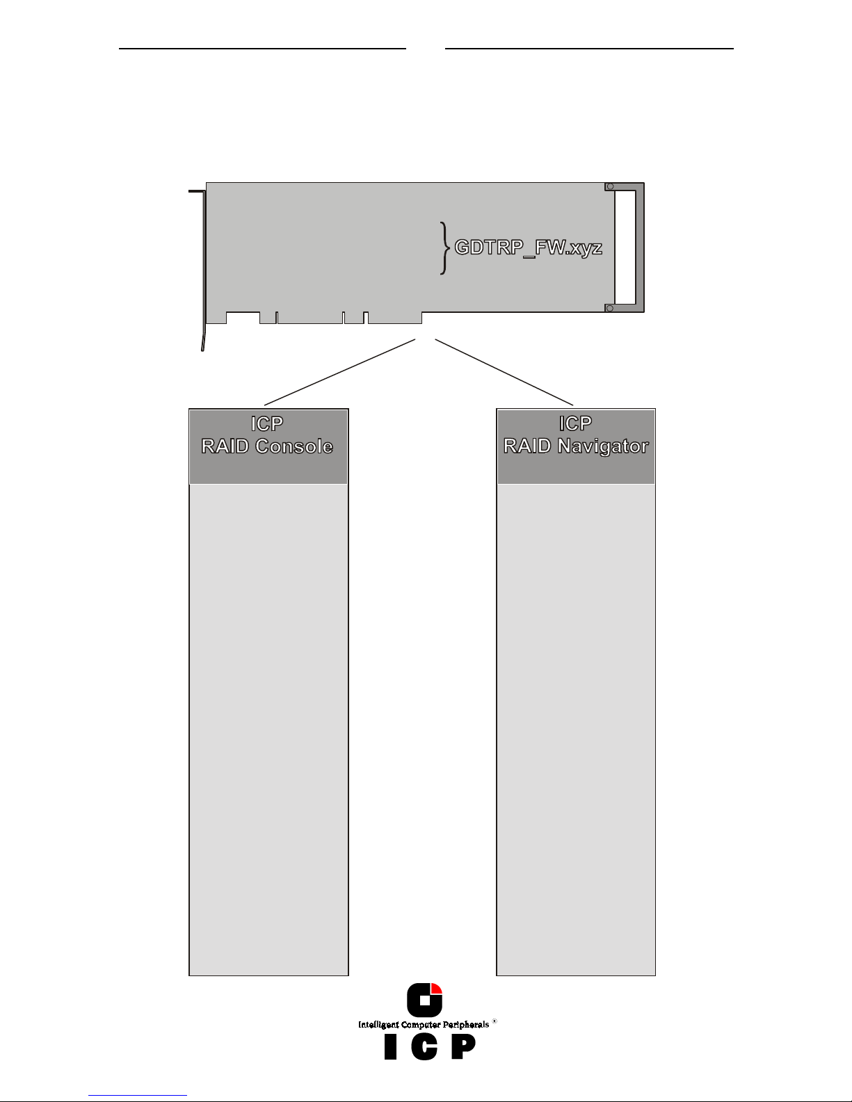
A.5.7 Configuration and Monitoring utilities “ICP RAID Console” and “ICP
RAID Navigator” Program ICPCON
These two configuration and monitoring programs are very flexible software tools that offer
many different configuration, diagnosis and monitoring functions during full-operation
conditions. ICPCON has a character-oriented user surface and is ideally suitable for NetWare and all types of UNIXes including Linux. ICPCON is also available at system boot
level as a rom resident tool (press <CTRL><G>). ICP RAID Navigator has a Windows NT
compliant graphical user interface (GUI) and can be operated under Windows
95/98/NT/2000. Booth tools can be used on the fileserver, or remotely from an authorized
workstation. The main functions are:
Confiuguration of Disk Arrays (also with EXPRESS function)
Monitoring the disk subsystem performance (KB/sec and I/Os per sec.)
Online configuration of the cache memory
Online check of the parity information of RAID 4 and RAID 5 Array Drives
Online capacity expansion and RAID level migration of existing Array Drives
Hot Plug and Hot Fix
Remote Operation (IPX, NetBIOS, TCP/IP), Messaging
24
ICP Firmware / ICP BIOS
and rom-residente
ICP RAID Console
(<CTRL>-<G>)
character-oriented
MS-DOS / DR-DOS
Windows 9x
Windows NT/2000
NetWare, SCO UNIX
SCO UnixWare
LINUX,
Solaris 7
Setup & Configure
Monitor
Replace
Controller
Physical Devices
Logical Drives
Array Drives
Host Drives
Controller
Physical Devices
Logical Drives
Array Drives
Host Drives
Failed Drives
Hot Plug
Graphical User Inte rface
Windows 9x
Windows NT/2000
Setup & Configure
Monitor
Replace
Controller
Physical Devices
Logical Drives
Array Drives
Host Drives
Controller
Physical Devices
Logical Drives
Array Drives
Host Drives
Failed Drives
Hot Plug
ICP Firmware / ICP BIOS / ICP Tools
25
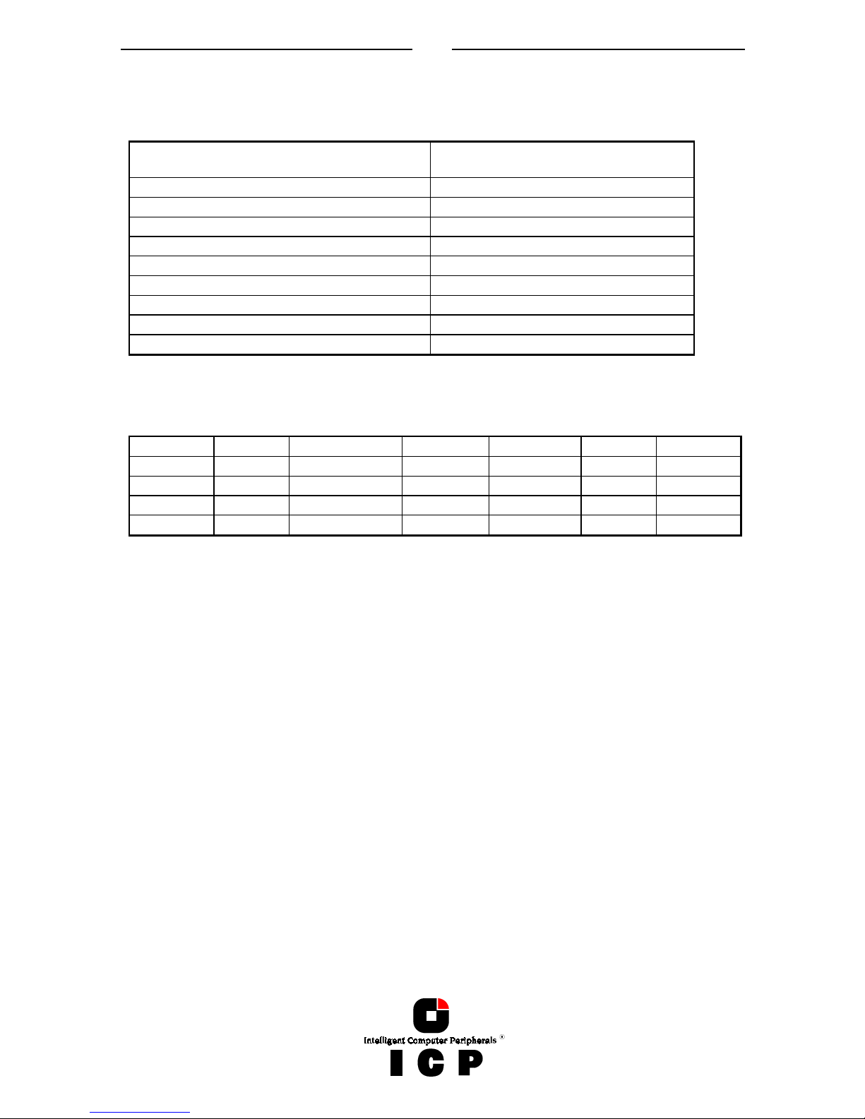
A.5.8 Operating System Driver Software
Drivers for the following operating systems are available:
Operating System Driver included with the Controller
Package
MS-DOS 3.3 to 6.x Yes
Novell NetWare 3.x, 4.x, 5.x Yes
SCO UNIX System V/386 3.2v5.x Yes
SCO UnixWare 2.x and 7 Yes
Windows NT, 3.5x, 4.x Yes
Windows 2000 Yes
Windows 95/98 Yes
Solaris 7 Yes
Linux Yes
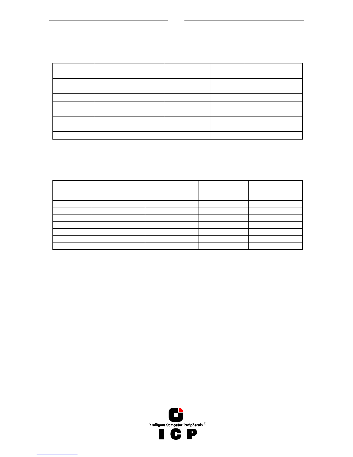
The following table shows how various devices are integrated by different operating systems. Please refer to the corresponding chapters of this User’s manual and the operating
system documentation for detailed installation information.
Hard Disk Remov. HDD CDROM Streamer WORM MOD
MS-DOS GDT ASPI or GDT ASPI ASPI ASPI ASPI/GDT
NetWare GDT GDT ASPI ASPI ASPI ASPI/GDT
UNIX/LINUX GDT GDT UNIX UNIX UNIX UNIX/GDT
Win. NT GDT Win.NT or GDT Win.NT Win.NT Win.NT Win.NT
GDT: Configurable with ICPCON (some MODs are recognized as a hard disk (see your MOD
manual). In this case, they too can be configured with ICPCON). ASPI: Integration by means
of an ASPI interface. UNIX/LINUX, Win.NT: Supported by the operating system.
A.5.9 ICP Controller Board Layout
The ICP Controller PCB (Printed Circuit Board) has several jumpers. In the following illustrations, all jumpers are shown in their factory setting. Under normal circumstances there is
no need to change these settings.
26
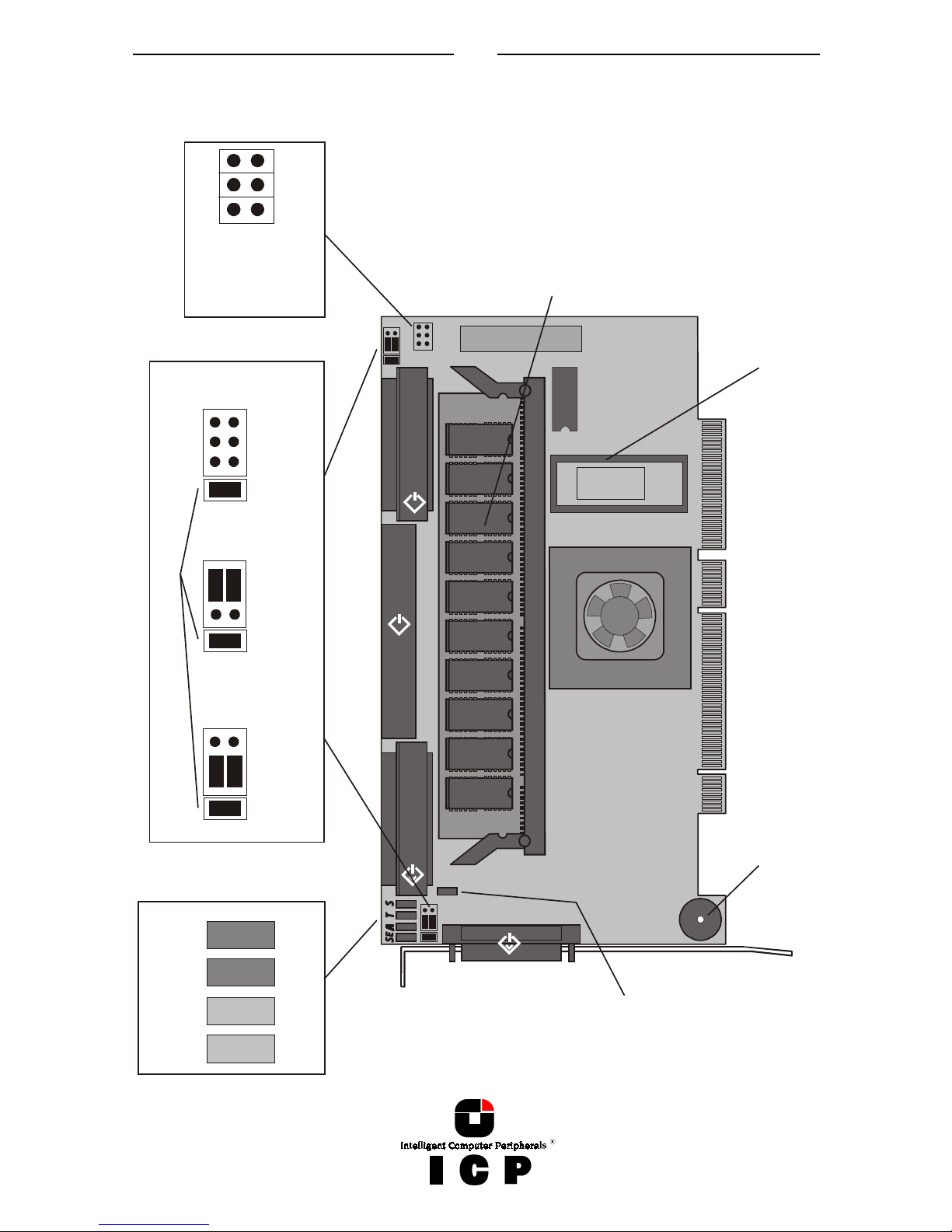
GDT7118RN, GDT7518RN and GDT7618RN Overall View
Acoustical
Alarm
Feature
Socket
Mode LED
ON = LVD
OFF = SE
DBPM Terminator
Channel A
SE Channel
Channel A
64-Bit PCI Bus Connector
Controller can also be operated
in a 32-Bit PCI Bus
Unbuffered
PC100 DIMM
16, 32, 64, 128MB
Standard and ECC
SUM
SE
A
Anode
Cathode
LED Connector
SCSI
Activity
SE A
T S
T=DMA
S=Status
Terminator Power (Default: Jumper closed)
Term in atio n
via Soft-Switches
(Default)
Term in atio n
always OFF
Term in atio n
always ON
SUM
SE
A
27
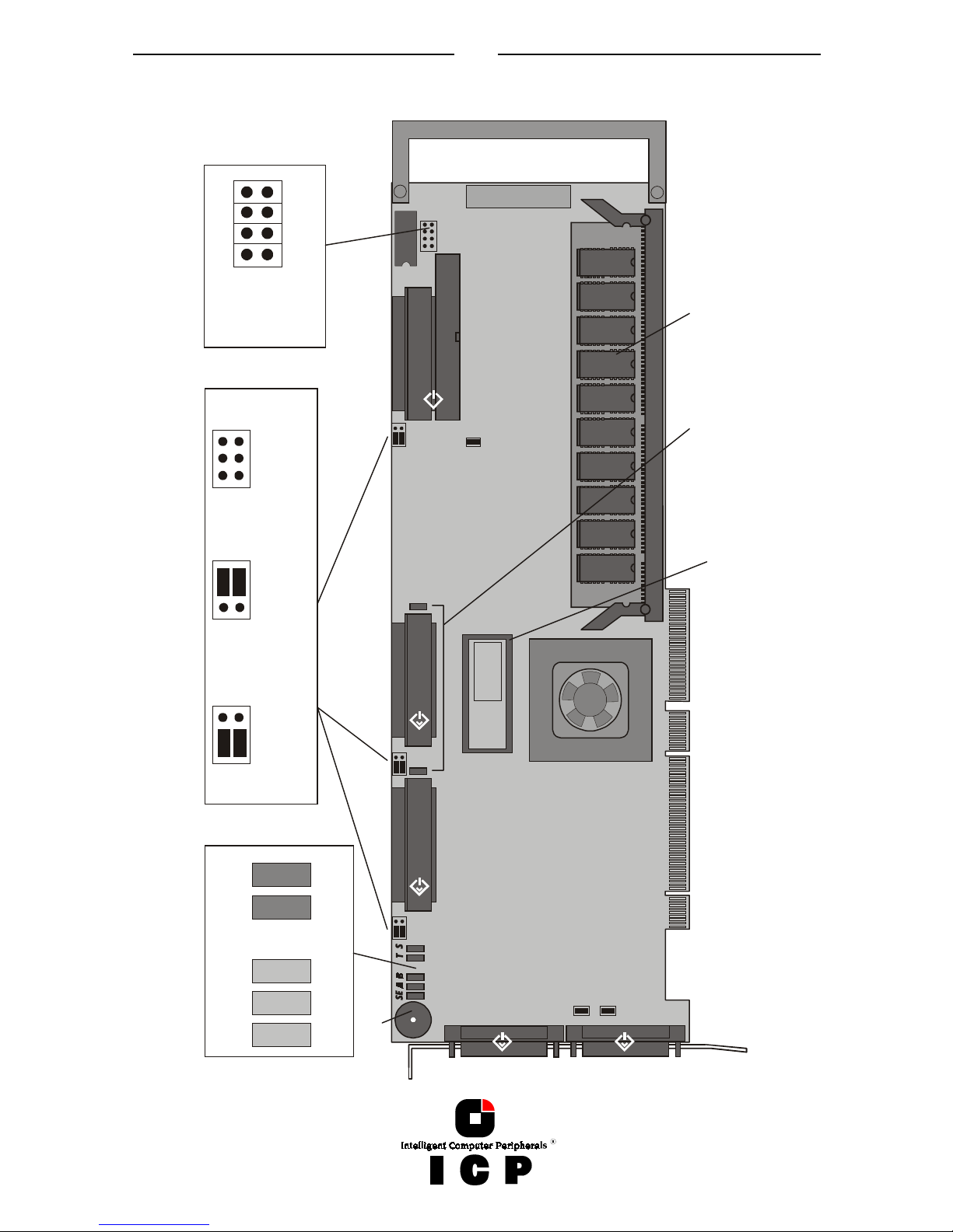
GDT7128RN, GDT7528RN and GDT7628RN Overall View
DBPM Terminator
TPA
TPB
TPSE
SUM
SE
A
B
Channel A Channel B
SE Channel
Channel BChannel A
SUM
SE
A
B
Anode
Cathode
LED Connector
Acoustical
Alarm
Feature
Socket
Mode LED
ON = LVD
OFF = SE
TPx = Terminator Power
(Default: Jumpers closed)
Terminator Power SE Channel
(Default: Jumper closed)
64-Bit PCI Bus Connector
Controller can also be operated
in a 32-B it PC I Bu s
Unbuffered PC100 DIMM
16, 32, 64, 128MB
Standard and ECC
Term inatio n
via Soft-Switches
(Default)
Term ination
always OFF
Term inatio n
always ON
SCSI Activity
SE A B
T S
T=DMA
S=Status
28
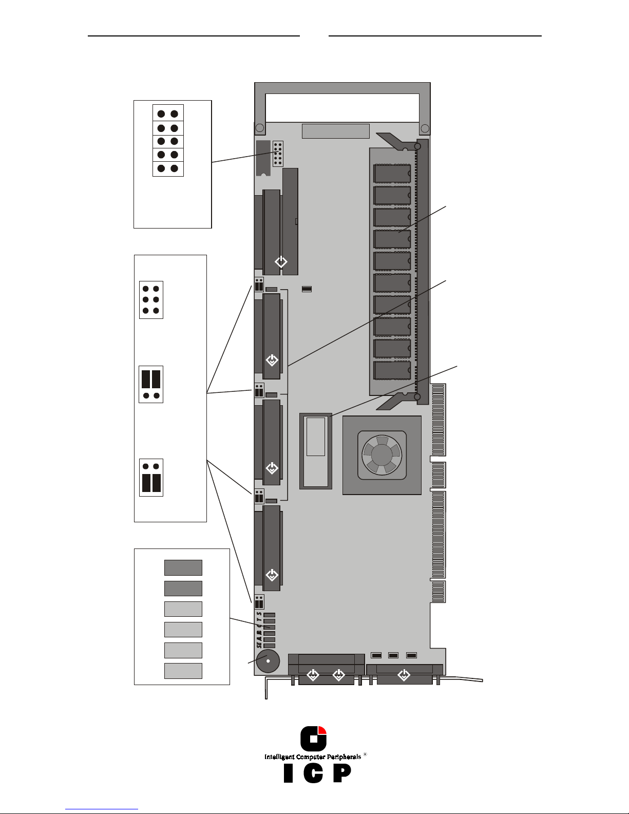
GDT7538RN and GDT7638RN Overall View
DBPM Terminator
TPA
TPB
TPC
TPSE
SUM
SE
A
B
C
Channel A Channel B Channel C
SE Channel
Channel B
Channel A (lower)
Channel C (upper)
SUM
SE
A
B
C
Anode
Cathode
LED Connector
Acoustical
Alarm
Feature
Socket
Mode LED
ON = LVD
OFF = SE
TPx = Term inator Pow er
(Default: Jumpers closed)
Terminator Power SE Channel
(Default: Jumper closed)
64-Bit PCI Bus Connector
Controller can also be operated
in a 32-B it PC I B us
Unbuffered PC100 DIMM
16, 32, 64, 128MB
Standard and ECC
Term ina tion
via Soft-Sw itches
(Default)
Term in ation
always OFF
Termination
always ON
SCSI Activity
SE A B C
T S
T=DMA
S=Status
29
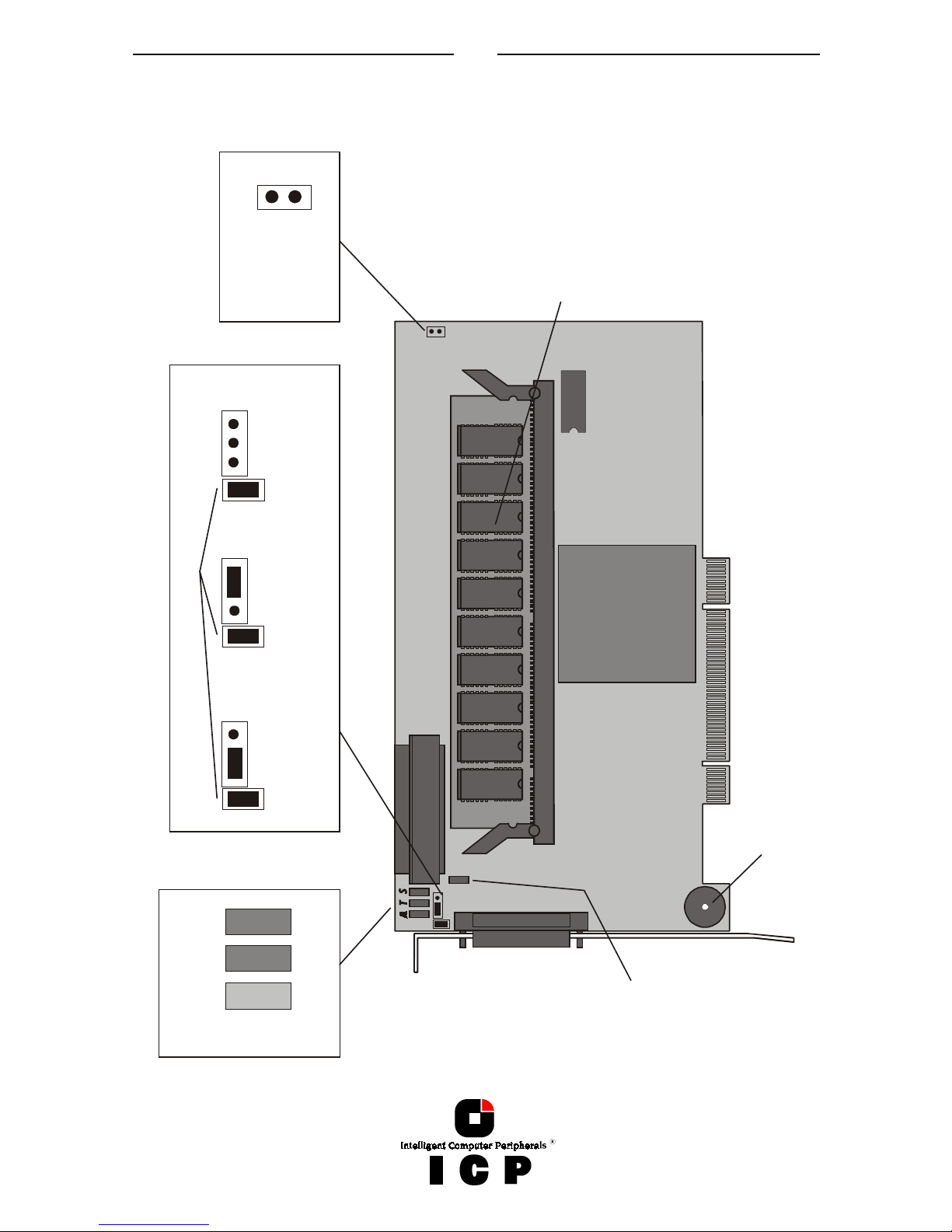
GDT6118RS and GDT6518RS Overall View
Acoustical
Alarm
Mode LED
ON = LVD
OFF = SE
Unbuffered
PC100 DIMM
16, 32, 64, 128MB
Standard and ECC
Anode
Cathode
LED Connector
SCSI
Activity
T S
T=DMA
S=Status
Terminator Power (Default: Jumper closed)
Term ination
via Soft-Switches
(Default)
Term in atio n
always OFF
Term ination
always ON
30
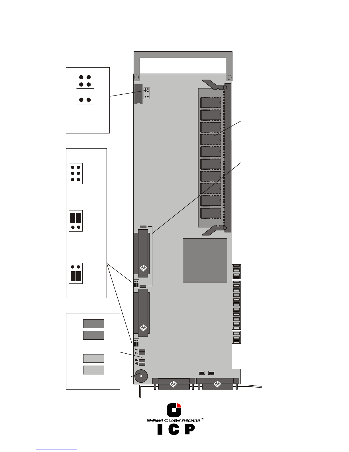
GDT6128RS and GDT6528RS Overall View
TPA
TPB
SUM
A
B
Channel A Channel B
Channel BChannel A
SUM
A
B
Anode
Cathode
LED Connector
Acoustical
Alarm
Mode LED
ON = LVD
OFF = SE
TPx = Terminator Power
(Default: Jumpers closed)
Unbuffered PC100 DIMM
16, 32, 64, 128MB
Standard and ECC
Termination
via Soft-Switches
(Default)
Term ination
always OFF
Term ination
always ON
SCSI Activity
A B
T S
T=DMA
S=Status
 Loading...