

Page 1
NDN5/GDJ
Downflow Only
Series
SAFETY CONSIDERATIONS
Recognize safety information. This is the safety-alert symbol _. When you see this symbol on the furnace and in instructions or
manuals, be alert to the potential for personal injury.
UnderstandthesignalwordDANGER, WARNING, orCAUTION. Thesewordeareusedwiththesafety-alertsymbol. DANGERidenti-
ties the most serious hazards will result in severe personal injury or death. WARNING signifies a hazard that could result in personal
injuryor death. CAUT__Nisusedt_identifyunsafepracticeswhichw_u_dresu_tinmin_rpers_na_injury_rpr_ductandpr_pertydam-
age.
Installing and servicing heating equipment can be hazardous due to gas and electrical components. Only trained and qualified person-
nel should install, repair, or service heating equipment.
Untrained service personnel can perform basic maintenance functions such as cleaning and replacing air filters. All other operations
must be performed by trained service personnel. When working on heating equipment, observe precautions inthe literature, on tags,
and on labels attached to or shipped with the unit and other safety precautions that may apply.
Follow all safety codes. In the United States, follow all safety codes including the current edition National Fuel Gas Code (NFGC) NFPA
No. 54/ANSIZ223.1. In Canada, refer to the current edition ofthe National Standard Canada CAN/CGA-Bt 49.1 - and .2-M91 Natural
Gas and Propane Installation Codes (NSCNGPIC). Wear safety glasses and work gloves. Havefire extinguisher available during start-
up and adjustment procedures and service calls.
These instructions cover minimum requirements and conform to existing national standards and safety codes. In some instances,
these instructions exceed certain local codes and ordinances, especially those that may not have kept up with changing residential
construction practices. We require these instructions as a minimum for a safe installation.
/k
Table of Contents
1.Installation............................... 2
2.Combustion&VentilationAir ................. 4
3.GasVent Installation ....................... 6
4.Horizontal................................ 7
5.GasSupplyandPiping ...................... 8
Design Certified
byAGA
Manufactured by:
Inter- City Products Corporation (USA)
Lewisburg, TN USA 37091
6.ElectricalWiring ........................
7.DuctworkandFilter ......................
8.ChecksandAdjustments..................
9.FurnaceMaintenance ....................
This furnace is not designed for use in mobile
homes, trailers or recreational vehicles. Such
use could result in property damage, bodily in-
jury and/or death.
LP3 4/14/97 441 01 2201 02
11
12
15
16
Page 2
1.Installation
Installation or repairs made by unqualified
persons can result in hazards to you and others.
Installation MUST conform with local codes or, in
the absence of local codes, with codes of the
country having jurisdiction.
The information contained in this manual is
intended for use by a qualified service technician
familiar with safety procedures and equipped
with the proper tools and test instruments.
Failure to carefully read and follow all instruc-
tions in this manual can result in furnace
malfunction, property damage, personal injury
and/or death.
NOTE: This furnace is design certified by the American Gas
Association and the Canadian Gas Association for installation in
the United States and Canada. Refer to the appropriate codes,
along with this manual, for proper installation.
• This furnace is NOT approved for installation in mobile
homes, trailers or recreation vehicles.
• Do NOT use this furnace as a construction heater.
Poison carbon monoxide gas hazard.
If this furnace is replacing a previously
common-vented furnace, it may be necessary to
resize the existing vent line and chimney to
prevent oversizing problems for the other
remaining appliances(s). See applicable codes
and Venting and Combustion Air Check in Gas
Vent Installation section.
Failure to properly vent this furnace or other
appliances can result in property damage,
personal injury and/or death.
Locationand Clearances
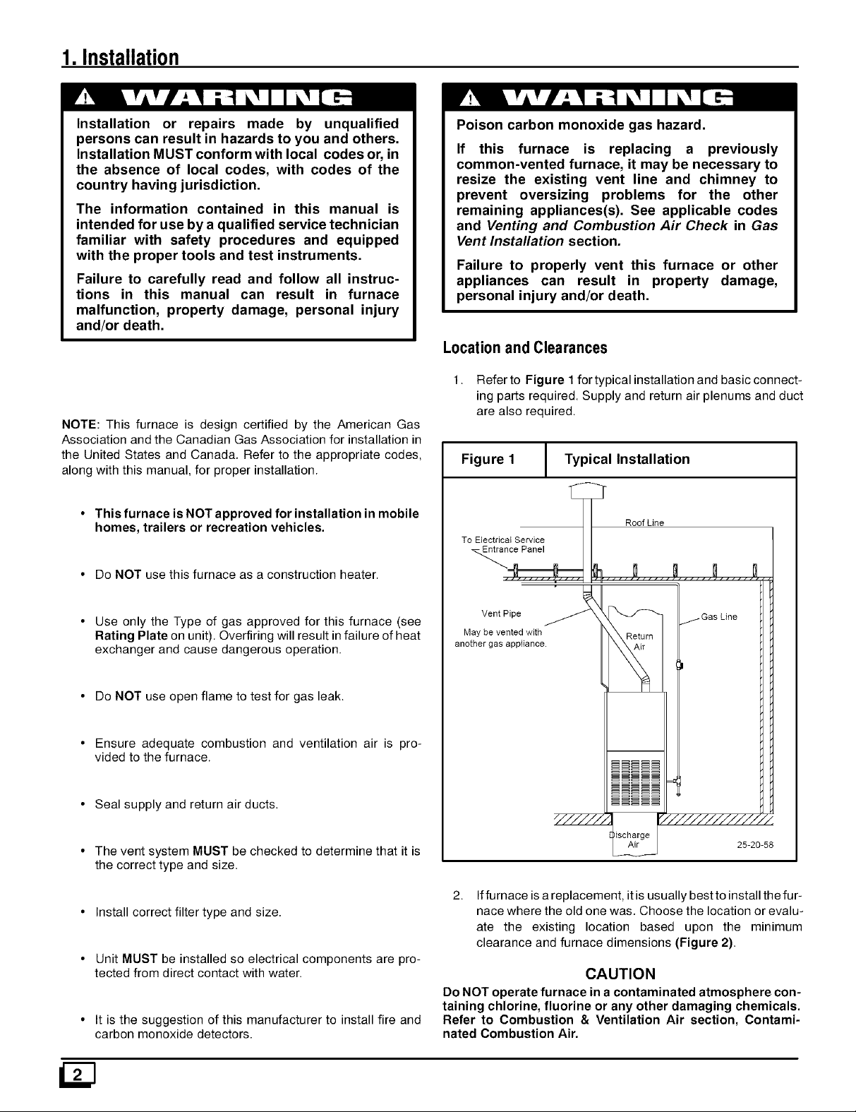
1. Refer to Figure 1for typical installation and basic connect-
ing parts required. Supply and return air plenums and duct
are also required.
Figure 1 1 Typical Installation
To ElectricaI Service
Entrance Panel
__ Roof Line
• Use only the Type of gas approved for this furnace (see
Rating Plate on unit). Overfiring will result infailure of heat
exchanger and cause dangerous operation.
• Do NOT use open flame to test for gas leak.
• Ensure adequate combustion and ventilation air is pro-
vided to the furnace.
• Seal supply and return air ducts.
• The vent system MUST be checked to determine that it is
the correct type and size.
• Install correct filter type and size.
• Unit MUST be installed so electrical components are pro-
tected from direct contact with water.
• It is the suggestion of this manufacturer to install fire and
carbon monoxide detectors.
May be vented with
another gas appliance.
VentPipe _ _Return __-GasLine
_ _///////////:
ischarge
2.
Iffurnace isa replacement, it is usually best to install the fur-
nace where the old one was. Choose the location or evalu-
ate the existing location based upon the minimum
clearance and furnace dimensions (Figure 2).
25-20-58
CAUTION
Do NOT operate furnace in a contaminated atmosphere con-
taining chlorine, fluorine or any other damaging chemicals.
Refer to Combustion & Ventilation Air section, Contami-
nated Combustion Air.
Page 3
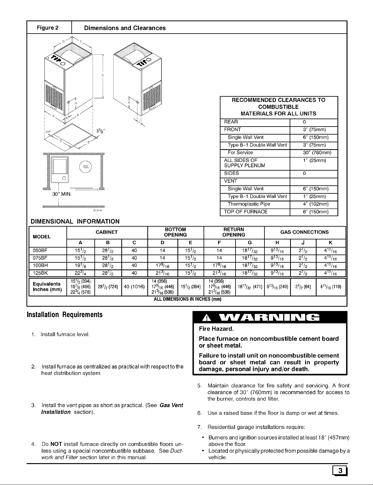
Figure 2 [ Dimensions and Clearances
DIMENSIONAL INFORMATION
MODEL
050BF
075BF
100BH
125BK
Equivalents
Inches (mm)
t51/2
t51/2
t91/6
223/4
19118(486)
I 151/2 394
223/4(578)
CABINET
A
B
281/2
281/2
281/2
281/2
281/2(724)
C
40
40
40
40
40 (1016) 179/16(446)
BOTTOM
OPENING
D E
14 151_
14 151_
17_16 151_
2t_16 151_
I 14(356)
213/16(538)
ALL DIMENSIONSIN INCHES(ram)
151_(394)
RECOMMENDED CLEARANCES TO
COMBUSTIBLE
MATERIALS FOR ALL UNITS
REAR 0
FRONT 3" (75mm)
Single Wall Vent 6" (150mm)
Type B-1 Double Wall Vent 3" (75mm)
For Service 30" (760mm)
ALL SIDES OF 1" (25mm)
SUPPLY PLENUM
SIDES 0
VENT
Single Wall Vent 6" (150mm)
Type B-1 Double Wall Vent 1" (25mm)
Thermoplastic Pipe 4" (102mm)
TOP OF FURNACE 6" (150mm)
RETURN
OPENING
F G
t4 1817/32
t4 1817/32
179/16 1817/32
213/16 1817/32
14(356) I
179/16(446) I 1817/32(47t)213/16(538)
GAS CONNECTIONS
H
913/16
913/16
913/16
913/16
913/16 (249)
J
21/2
21/2
21/2
21/2
21/2(64)
K
411/16
411/16
411/16
411/16
411t16(119)
Installation Requirements
1. Install furnace level.
Install fumace as centralized as practical with respect to the
heat distribution system.
Install the vent pipes as short as practical. (See Gas Vent
Installation section).
Do NOT install furnace directly on combustible floors un-
less using a special noncombustible subbase. See Duct-
work and Filter section later in this manual.
Fire Hazard.
Place furnace on noncombustible cement board
or sheet metal.
Failure to install unit on noncombustible cement
board or sheet metal can result in property
damage, personal injury and/or death.
5. Maintain clearance for fire safety and servicing. A front
clearance of 30" (760mm) is recommended for access to
the burner, controls and filter.
6. Use a raised base if the floor is damp or wet at times.
7. Residential garage installations require:
• Burners and ignition sources installed at least 18" (457mm)
above the floor.
• Located or physically protected from possible damage by a
vehicle.
G3
Page 4
2. Combustion& VentilationAir
Poison carbon monoxide gas hazard.
Use methods described here to provide
combustion and ventilation air.
Failure to provide adequate combustion and
ventilation air can result in personal injury
and/or death.
Furnaces require ventilation openings to provide sufficient air for
proper combustion and ventilation of flue gases. All duct or open-
ings for supplying combustion and ventilation air must comply
with the gas and electrical codes, or inthe absence of local codes,
the applicable national codes.
When the installation is complete, check that all appliances have
adequate combustion air and are venting properly. See Venting
And Combustion Air Check in this manual.
ContaminatedCombustionAir
Installations in certain areas or types of structures will increase
the exposure to chemicals or Halogens which may harm the fur-
nace. These instances must use only outside air for combustion.
The following areas or types of structures may contain or have ex-
posure to the substances listed below. The installation must be
evaluated carefully as it may be necessary to provide outside air
for combustion.
• Commercial buildings.
• Buildings with indoor pools.
• Furnaces installed in laundry rooms.
• Furnaces installed in hobby or craft rooms.
• Furnaces installed near chemical storage areas.
• Permanent wave solutions for hair.
• Chlorinated waxes and cleaners.
• Chlorine based swimming pool chemicals.
• Water softening chemicals.
• De-icing salts or chemicals.
• Carbon tetrachloride.
• Halogen type refrigerants.
• Cleaning solvents (such as perchloroethylene).
• Printing inks, paint removers, varnishes, etc..
• Hydrochloric acid.
• Sulfuric Acid.
• Solvent cements and glues.
• Antistatic fabric softeners for clothes dryers.
• Masonry acid washing materials.
Confined SpaceInstallation
NOTE: A confined space is defined as an area with less than 50
cubic feet(1.4m s) per 1,000 BTUH input rating for all gas ap-
pliances installed in the area.
Air Openingsand Connecting Ducts
1. Total input rating for all gas appliances MUST be consid-
ered when determining free area of openings.
2. Connect ducts or openings directly to outside.
3. When screens are used to cover openings, they MUST be
no less than 1/4" (6ram) mesh.
4. The minimum dimension of rectangular air ducts MUST
NOT be less than 3" (75mm).
5. When sizing grille or louver, use the free area of opening. If
free area is NOT stamped or marked on grill or louver, as-
sume a 20% free area for wood and 60% for metal.
Requirements
1. Provide confined space with sufficient air for proper com-
bustion and ventilation of flue gases using horizontal or ver-
tical ducts or openings.
2. Figure 3 illustrates howto provide combustion and ventila-
tion air. A minimum of two permanent openings, one inlet
and one outlet, are required.
/33
Page 5
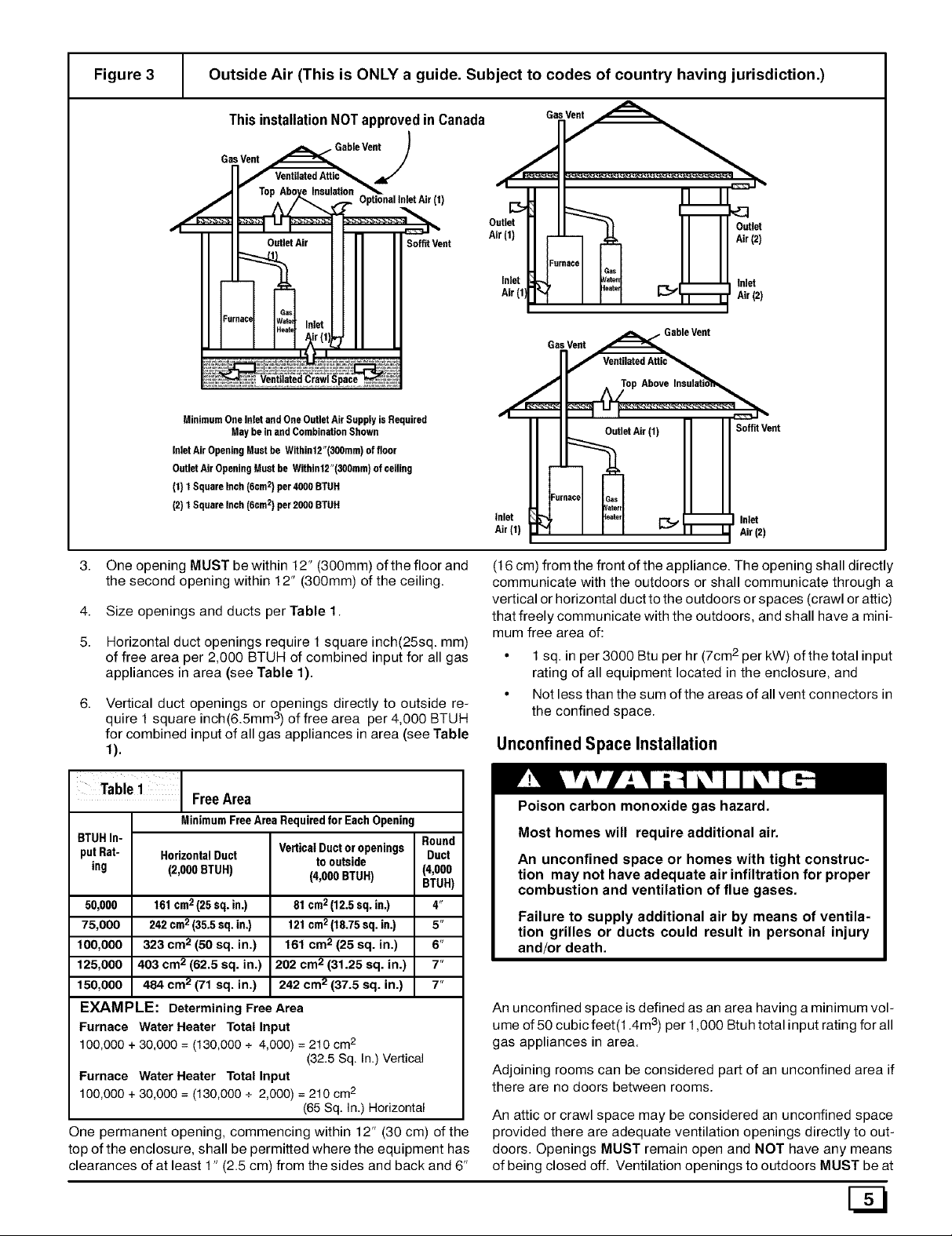
Figure 3 Outside Air (This is ONLY a guide. Subject to codes of country having jurisdiction.)
ThisinstallationNOTapprovedin Canada Gas Vent
GasVent . GableVent)
=/
E_
Soft, Vent
Outlet
Air (1)
Inlet
Air(1
Furnace
' ieat_
Gas
fatal
Outlel
Air (2',
m
Inlet
Air (2
MinimumOneInlet andOne OutletAirSupplyinRequired
InletAir OpeningMustbe Within12"(300mm)of floor
OutletAir OpeningMustbe Withint2"(300ram)of ceiling
(t) 1Square Inch(6cm2)per4000 BTUR
(2)1Square Inch(6cm2)per2000 BTUH
3.
One opening MUST be within 12" (300mm) of the floor and
May be inand CombinationShown
the second opening within 12" (300mm) of the ceiling.
4.
Size openings and ducts per Table 1.
5.
Horizontal duct openings require 1 square inch(25sq, mm)
of free area per 2,000 BTUH of combined input for all gas
appliances in area (see Table 1).
Vertical duct openings or openings directly to outside re-
I 3
qu're 1 square inch(6.5mm ) of free area per 4,000 BTUH
for combined input of all gas appliances in area (see Table
t).
Table1
BTUHIn-
putRat- HorizontalDuct
ing (2,000BTUH)
50,000 161cm2(25 sq. in.)
75,000 242cm2(35.5sq.in.)
100,000 323 cm 2 (50 sq. in.)
125,000 403 cm 2 (62.5 sq. in.)
150,000 484 cm 2 (71 sq. in.)
FreeArea
MinimumFreeArea RequiredforEach Opening
VerticalDuctoropenings
to outside
(4,000BTUH)
81 cm2(12.5sq.in.)
121cm2(18.75sq. in.)
161 cm 2(25 sq. in.)
202 cm 2 (31.25 sq. in.)
242 cm2 (37.5 sq. in.) 7"
Round
Duct
(4,000
BTUH)
4"
5"
6"
7"
EXAMPLE: Determining Free Area
Furnace Water Heater Total Input
100,000 + 30,000 = (130,000 + 4,000) = 210 cm2
Furnace Water Heater Total Input
100,000 + 30,000 = (130,000 + 2,000) = 210 cm 2
One permanent opening, commencing within 12" (30 cm) of the
top of the enclosure, shall be permitted where the equipment has
clearances of at least 1" (2.5 cm) from the sides and back and 6"
(32.5 Sq. In.) Vertical
(65 Sq. In.) Horizontal
GasVent
11
Inlet t
Air(t)
._, GableVent
f VentilatedAttic_
Top Above Insulatio_h_=
I I _ I_"
OutletAir (1) II I SoffitVent
_ Inlet
Air(2)
(16 cm) from the front of the appliance. The opening shall directly
communicate with the outdoors or shall communicate through a
vertical orhorizontal duct to the outdoors or spaces (crawl or attic)
that freely communicate with the outdoors, and shall have a mini-
mum free area of:
• 1 sq. in per 3000 Btu per hr (7cm2per kW) of the total input
rating of all equipment located in the enclosure, and
• Not less than the sum of the areas of all vent connectors in
the confined space.
UnconfinedSpace Installation
Poison carbon monoxide gas hazard.
Most homes will require additional air.
An unconfined space or homes with tight construc-
tion may not have adequate air infiltration for proper
combustion and ventilation of flue gases.
Failure to supply additional air by means of ventila-
tion grilles or ducts could result in personal injury
and/or death.
An unconfined space is defined as an area having a minimum vol-
ume of 50 cubic feet(1.4m 3)per 1,000 Btuh total input rating for all
gas appliances in area.
Adjoining rooms can be considered part of an unconfined area if
there are no doors between rooms.
An attic or crawl space may be considered an unconfined space
provided there are adequate ventilation openings directly to out-
doors. Openings MUST remain open and NOT have any means
of being closed off. Ventilation openings to outdoors MUST be at
Page 6

least1squareinch(25mm2)offreeareaper4,000BTUHoftotal
inputratingforallgasappliancesinarea.
Inunconfinedspaces,infiltrationshouldbeadequatetoprovide
airforcombustion,ventilationanddilutionoffluegases.However,
inbuildingswithunusuallytightconstruction,additionalairMUST
beprovidedusingthemethodsdescribedinsectiontitledCon-
fined Space Installation:
2. Doors and openable windows are weather stripped and
3.
Other openings are caulked or sealed. These include joints
around window and door frames, between sole plates and
floors, between wall-ceiling joints, between wall panels, at
penetrations for plumbing, electrical and gas lines, etc.
VentilationAir
Unusually tight construction is defined as: Construction with
1 . Walls and ceilings exposed to the outside have a continu-
ous, sealed vapor barrier. Openings are gasketed or
sealed and
3. GasVent Installation
Poison carbon monoxide gas, fire and explo-
sion hazard.
Read and follow all instructions in this section.
Failure to properly vent this furnace can result in
property damage, personal injury and/or death.
Install the vent in compliance with codes of the country having ju-
risdiction and the GAMA venting tables, local codes or ordi-
nances and these instructions.
These fan assisted combustion furnaces have been classified as
Category I appliances which means that they MUST operate with
a negative vent pressure. Category III classification approval has
been obtained for these furnaces if vented horizontally with a
combination single wall metal/high temperature plastic
venting system.
Category! Safe Venting Requirements
NOTE: The following instructions comply with the United States
National Fuel Gas Code.
Ifa Category I vent passes through an attic, any concealed
space or floor, use ONLY Type B or Type L double wall vent
pipe. If vent pipe passes through interior wall, use type B
vent pipe with ventilated thimble ONLY.
2. Do NOT vent furnace into any chimney serving an open
fireplace or solid fuel burning appliance.
Use the same diameter Category I connector or pipe as the
furnace minimum vent size as noted on label adjacent to
the flue outlet, except as permitted by the GAMA venting
tables.
4.
Keep vertical Category I vent pipe or vent connector runs
as short and direct as possible.
5.
Vertical outdoor runs of type B or ANY single wall vent pipe
below the roof line are NOT permitted.
6.
Slope all horizontal runs upwards away from furnace a
minimum of 1/4" (6mm) per foot.
7.
Support all horizontal vent pipe every 6' (2m) using proper
clamps and metal straps.
8.
Check existing gas vent or chimney to ensure they meet
clearances and local codes.
Some provincial codes and local municipalities require ventilation
or make-up air be brought into the conditioned space as replace-
ment air. Whichever method is used, the mixed return air temper-
ature across the heat exchanger MUST not fall below 60°F (15 ° c)
or flue gases will condense in the heat exchanger. This will short-
en the life of the heat exchanger and possibly void your warranty.
9.
The furnace MUST be connected to a factory built chimney
or vent complying with a recognized standard. Venting
into a masonry or concrete chimney is only permitted
as outlined in the GAMA venting tables or Masonry
Chimney section in these instructions.
10.
All Category I and Category Ill pipe MUST be attached to
the factory provided 3" vent pipe where itexits the furnace.
Do NOT remove the factory installed 3" vent pipe from vent
enclosure. At least two (2) holes are recommended to at-
tach pipe firmly. Ifyour furnace came with a section of prein-
stalled vent pipe, inspect connection to ensure connection
is tight and all screws are in place.
Poison carbon monoxide gas hazard.
If this furnace is replacing a previously
common-vented furnace, it may be necessary
to resize the existing chimney liner or vent to
prevent over sizing problems for the other
remaining appliances(s). See codes of country
having jurisdiction.
Failure to properly vent this furnace or other
appliances can result in property damage,
personal injury and/or death.
Venting and Combustion Air Check
NOTE: Ifthis installation removes an existing furnace from a vent-
ing system serving one or more other appliances, and to make
sure there is adequate combustion air for all appliances, MAKE
THE FOLLOWING CHECK.
1. Seal any unused openings in the venting system.
2.
Visually inspect the venting system for proper size and hori-
zontal pitch to ensure there is no blockage or restriction,
leakage, corrosion or other deficiencies which could cause
an unsafe condition.
3.
Insofar as is practical, close all doors and windows and all
doors between the space in which the appliance(s) remain-
ing connected to the venting system are located and other
spaces of the building.
4.
Turn on clothes dryers and any appliance not connected to
the venting system. Turn on any exhaust fans, such as
range hoods and bathroom exhausts, so they will operate
at maximum speed. Do not operate a summer exhaust fan.
Close fireplace dampers.
Page 7

Follow the lighting instructions for each appliance being in-
5 Venting to Existing MasonryChimney
spected. Adjust thermostat so appliance(s) will operate
continuously.
Allow 5 minutes of main burner operation, then check for
spillage at the draft hood relief opening of each appliance.
Use the flame of a match or candle (Figure 4).
Figure 4 Vent Check
NOTE: The tables and notes referred to below are found in the
most recent printing of the GAMA venting tables.
Dedicated venting of one fan assisted furnace into any ma-
sonry chimney is prohibited. The chimney must first be lined
with either type Bvent sized in accordance with tables t or 2 or a
listed single wall, rnetal lining systern, sized in accordance with
the following:
Vent Pipe "-'_1 I A/ Draft Hood
Typical Gas
Water Heater
Match
! I
7. After it has been determined that each appliance vents
properly, return doors, windows, appliances etc. to their
normal condition.
8. If improper venting is observed, the cause MUST be cor-
rected.
NOTE: If flame pulls towards draft hood, this indicates sufficient
infiltration air.
4. HorizontalVenting
This section of the installation instructions deal with both Catego-
ry I and Category III installation.
CAUTION
It isthe responsibility of the installer to properly termi-
nate the vent and provide adequate shielding, This is
essential in order to avoid water/ice damage to build-
ing, shrubs and walk-ways.
Listed, corrugated metallic chimney liner systems in masonry
chimneys shall be sized by using GAMA tables 1 or 2 for dedi-
cated venting and GAMA tables 3 or 4 for common venting with
the maximum capacity reduced by 20% (0.80 X maximum capac-
ity) and the minimum capacity as shown in the applicable table.
Corrugated metal vent systems installed with bends or offsets re-
quire additional reduction of 10% of the vent capacity for each 90°
elbow.
NOTE: Two(2) 45 ° elbows are equivalent to one (1 90° elbow.
Combined Venting into a MasonryChimney
Venting into a masonry or concrete chimney is only per-
mitted as outlined in the GAMA venting tables. Follow all safe
venting requirernents.
NOTE: See section"Masonry Chimney Venting"
• Avoid any installation where leakage of flue products
can communicate with indoor living areas.
• Use Only Vent System Pipe & Fittings Constructed of Amoco
Radel® A-200 Material from the following manufacturers:
• Only Ultra Vent@ (date code 08/01/93 or later), Plex-
vent "II"®, & Selvent®, which are manufactured with
Radel A-200®.
Category I FurnacesWith External Power Venters
Inorder to maintain a Category I classification offan assisted fur-
naces when vented horizontally with sidewall termination, a pow-
er venter is REQUIRED to maintain a negative pressure in the
venting system. Please consult the Fields Controls Co. or Tjern-
lund Products, Inc. for power venters certified for use with our fur-
naces.
Category III Furnaces Without External PowerVenters
A horizontal vent system with side wall termination WITHOUT a
power venter MUST use a combination single wall metal/high
temperature plastic venting system and sealants and be installed
as shown in this section. Furnaces using this type of venting sys-
tem have a Category III classification.
Horizontal Venting With Metal/Plastic Materials
When metal/plastic venting materials are used to horizontally
vent an induced draft furnace, positive pressure exists throughout
the horizontal vent. Special high temperature plastic pipe and fit-
tings must be used and the furnaces using this method of side wall
venting have a Category III classification.
Important Installation Requirementsfor Category II!
Venting withThermoplastic Materials
• Install Only in UNINHABITED Spaces (i.e.: crawl spaces, at-
tics, vent chases, etc.)
• Be Thoroughly Familiar with the Vent Manufacturers Current
Instructions.
Specific instructions may vary. Use only the installa-
tion methods prescribed by the manufacturer of the
material you are using in accordance with Inter-City
Products restrictions.
Poison carbon monoxide poisoning, fire and
explosion hazard.
Approved vent materials listed MUST be used.
Failure to use approved vent materials specified
can result in property damage, personal injury
and/or death.
General Safe Venting Requirements
Do NOT connect this Category III vent directly into a B-Vent or
factory-built chimney nor use this vent for appliances burning
wood, coal, or oil or incinerators of any kind.
Do NOT insulate vent pipe or fittings.
1. 50,000 thru 125,000 BTU input models are approved for
use with 3" dia. vent. 150,000 BTU input models require 4"
dia. vent.
Page 8

Themaximumventlength,regardlessofpipediameter,is
30'(10m)plusamaximumofuptothree(3)90°longradius
or"sweep"elbows.Iffewerthanthreeelbowsareused,
maximumventlengthisstill30'(10m).
A12"(300mm)minimumto18"(450mm)maximumsection
ofsinglewall26gauge(.134"[.86mm])minimumgalva-
nizedorstainlesssteelisrequiredattheventcollarofthe
furnacepriortoconnectionoftheplasticventpipe.Use3"
diameterfor50,000through125,000Btuhinputmodels
and4"diameterfor150,000Btuhinputmodels.
4. Minimumof18"(450mm)ventfromthefurnaceconnector
isrequiredbeforethefirst90°elbow.
Maintaina4"(102mm)minimumairspacetocombustibles
fromallsectionsoftheventsystem,exceptwhereawall
thimbleisusedforhorizontalventing,orasallowedbylocal
ornationalcodes.
Aplasticteeventoutletwithscreenforventterminationis
requiredtobespacedadistanceof8" fromtheexterior
wall.Ifpossible,thewallthroughwhichtheventwillpass
shouldnotbeexposedtotheprevailingwind.Ifthisisnot
possible,stepstoprotecttheventterminationfromstrong
windsshouldbeconsidered,suchasafenceorahedge.
Vent Termination
3.
The venting system shall terminate at least 4' (1220mm)
below, 4' (1220mm) horizontally from, or 1, (300mm) above
any door, window, or gravity air inlet into any building. The
vent tremination shall be located at least 4' (1220mm) hori-
zontally from any electric meter, gas meter, regulator, and
any relief equipment. These distances apply only to U.S.
installations.
4.
The vent termination shall terminate at least 3' (914mm)
above any forced air inlet located within 10' (3.1m). See
Figure 5.
Figure 5 Vent Termination Clearances
(United States Only, )
See Canadian Fuel Gas Code _ 0therThan
0ther Than
DirectVent
Terminal
\
OtherThan
DirectVent Forced Air
Terminal Intet
Vent Termination Clearances
The vent termination must be located at least 12" (300mm)
above ground or normally expected snow accumulation
levels.
Do NOT terminate over public walkways. Avoid areas
where condensate may cause problems such as above
planters, patios, or adjacent to windows where steam may
cause fogging.
5. GasSupplyandPiping
Fire and explosion hazard.
Natural Gas
Models designated for Natural Gas are to be used
with Natural Gas ONLY.
Failure to follow these instructions can result in
property damage, personal injury and/or death.
10-11-36
5. In Canada, the Canadian Fuel Gas Code takes precedence
over the preceding termination instructions.
Venting Through a Non-Combustible and Combustible
Wall
Please consult Thermoplastic vent manufacturer for proper meth-
od of venting througn a non-combustible and combustible wall.
Table 2
Gas Manifold
Type Min. Pressure
Natural 4.5" 3.5"
Propane 11" t 0"
Recommended Max.
Gas Pressures
Supply Pressure
7" 14"
(1.7 kPa) (3.5 kPa)
11" 14"
(2.7 kPa) (3.5 kPa)
(1.1 kPa) (0.9 kPa)
(2.7 kPa) (2.5 kPa)
NaturalGas Input RatingCheck
Gas Supply Requirements
• Use only the Type of gas approved for this furnace. See rat-
ing plate for approved gas type.
• Gas input must not exceed the rated input shown on the rat-
ing plate. Overfiring will result in failure of heat exchanger
and cause dangerous operation.
• Do not allow minimum supply pressure to vary downward.
Doing so will decrease input to furnace. Refer to Table 2 for
Gas supply and manifold pressures.
/SJ
The gas meter can be used to measure input to furnace. Rating is
based on a natural gas BTU content of 1,000 BTU's per cubic foot.
Check with gas supplier for actual BTU content.
1. Turn OFF gas supply to all appliances other than furnace
and start furnace.
2. Time how many seconds it takes the smallest dial on the
gas meter to make one complete revolution. Refer to Ex-
ample.
Note: If meter uses a 2 cubic foot dial divide results (se-
conds) by two.
Page 9

Example
Natural Gas No. of Seconds Time Per Cubic BTU Per
BTU Content Per Hour Foot in Seconds Hour
1,000 3,600 48 75,000
1,000 x 3,600 ÷ 48 = 75,000 BTUH
3. Relight all appliances and ensure all pilots are operating.
Orifice Sizing
NOTE: Factory sized orifices for natural and LP gas are listed in
the furnace Technical Support manual.
Ensure furnace is equipped with the correct main burner orifices.
Refer to Table 3 for correct orifice size for a given heating value
and specific gravity for natural and propane gas. Note that this
chart is ONLY for installations below 2000' in altitude.
Table 3
Gas Manifold Specific (BTU per
Type Pressure Gravity Cubic Ft.)
Natural 800
Propane 2.5kPa 1.53 2500
Orifice Sizes (below 2000')
Heating Value
3.5" w.c. 900
0.9kPa 0.6
W.C.
10" W.C.
w.c.
1000
1100
Orifice Size
(Drill #)
40
41
42
43
54
OperationAbove 2000' Altitude
These units may be used at full input rating when installed at alti-
tudes up to 2000'. When installed above 2000', the input must be
decreased 4% for each 1000' above sea level. This may be ac-
complished by a simple adjustment of manifold pressure or an ori-
fice change, or a combination of a pressure adjustment and an
orifice change. The changes required depend on the installation
altitude and the heating value of the fuel. TABLES 4 & 5 show the
proper furnace manifold pressure and gas orifice size to achieve
proper performance based on elevation above sea level for both
natural gas and propane.
To use the natural gas table, first consult your local gas utility for
the heating value of the gas supply. Select the heating value on
the vertical border and follow across the table until the appropriate
elevation for the installation is reached. The first value in the box
at the intersection of the heating value and elevation will be the
manifold pressure required. If a gas orifice change is also re-
quired, the box is shaded. The required orifice size is shown at the
bottom of the table.
Sea Level
High Altitude Input Rate = Nameplate x (Multiplier)
Input Rate
Elevation High Altitude
2000'-2999' 0.92
3000'-3999' 0.88
4000'-4999' 0.84
5000'-5999' 0.80
6000'-6999' .0.76
7000'-8000' .0.72
Multiplier
Fire, Explosion, Poison carbon monoxide gas haz-
ard.
This conversion shall be done by a qualified service
For installations above 4000', the inlet air restrictor of the com-
bustion air blower MUST be changed, whether gas has been der-
ated by the utility or orifices have been changed.
agency in accordance with the Manufacturer's
instructions and all applicable codes and require-
ments, or in the absence of local codes, the applica-
ble national codes.
A High Altitude Kit is available which includes restrictors, orifices
and installation instructions.
Natural Gas - 1160993
Failure to follow these instructions exactly can re-
LP Gas - 1160992
sult in property damage, personal injury and/or
death.
MANIFOLD PRESSURE AND ORIFICE SIZE FOR HIGH ALTITUDE APPLICATIONS
Table 4
HEATING VALUE
BTU/CU. FT.
800
850
900
950
t 000
t 050
1100
Orifice Size
;HADED AREA REQUIRES ORIFICE CHANGE.
NATURAL GAS
2000 to
2999
3.5" wc
3.5" wc
3.5" wc
3.3" wc
3.0" wc
2.7" wc
2.5" wc
#42
MEAN ELEVATION FEET ABOVE SEA LEVEL
3000 to 4000 to
3999 4999
3.5" wc 3.5" wc
3.5" wc 3.5" wc
3.4" wc 3.1" wc
3.1" wc 2.8" wc
2.8" wc 2.5" wc
2.5" wc 2.3" wc
2.3" wc
#42
3.5" wc " 3.2" wc 2.9"wc • 2.6" wc
#45 " #45 " #45 " #45
5000 to
5999
3.5" wc
3.2" wc
2.8" wc
2.5" wc
2.3" wc
3.5" wc
6000 to
6999
3.2" wc
2.9" wc
2.5" wc
2.3" wc
3.5" wc ' 3.1" wc
3.2" wc • 2.8" wc
NO SHADING INDICATES MANIFOLD PRESSURE CHANGE ONLY.
7000 to
8000
2.9" wc
2.6" wc
2.3" wc
3.5" wc
Page 10

PROPANE
MEAN ELEVATION FEET ABOVE SEA LEVEL
HEATINGVALUE 0 to 2000 to 3000 to 4000 to 5000 to 6000 to 7000 to
BTU/CU. FT. 1999 2999 3999 4999 5999 6999 8000
2500 10.0" wc 10.0" wc 9.4" wc 10.0" wc 9.8" wc 8.8" wc 7.9"wc
Orifice Size #54 #54 #54 #55 #55 #55 #55
NOTE:NATURAL GAS DATA BASED ON 0.60 SPECIFIC
GRAVITY. PROPANE DATA BASED ON 1.53
SPECIFIC GRAVITY. FOR FUELS WITH DIFFERENT
SPECIFIC GRAVITY CONSULT THE LATEST EDITION
OF THE NATIONAL FUEL GAS CODE ANSI Z223.1
and CAN B149.
ChangingOrifices
1 . After disconnecting power and gas supply to the furnace,
remove the access door, exposing gas valve and burner
compartment.
2. Disconnect gas line, pilot tubing from gas valve so manifold
can be removed.
3. Disconnect wiring at gas valve. Be sure to note the proper
location of any and all electrical wiring disconnected.
4. Replace the four (4) screws holding the manifold and gas
valve to the manifold supports. Do not discard any screws.
See Figure 6.
Figure 6 Manifold
7. Tighten orifices so there is 11/8" from the face of the orifice
to the back side of the manifold. See Figure 7.
8. Reassemble all parts in reverse order as removed. Besure
to engage the main burner orifices in the proper opening in
the burners.
9. After reassembling, turn gas on and check all joints for gas
leaks using a soapy solution. All leaks must be repaired im-
mediately.
Gas Piping Requirements
1 . Install gas piping in accordance with local codes, or in the
absence of local codes, the applicable national codes.
2. It is recommended that a manual shutoff valve be installed
in the gas supply line outside the unit. Locate valve as close
to the furnace as possible where it is readily accessible.
Refer to Figure 8.
Figure 8 Typical Gas Piping
Elbow and
short nipple
Manual
Valve
DO not secure or support
connector to furnace
25_20_95
5. Carefully remove the manifold assembly.
6. Remove the orifices from the manifold and replace them
with proper sized orifices.
Figure 7 Clearances
Measure 11/8" (27mm) from face
of orifice to the back side of the
manifold.
DripLeg
and pipecap
Leftsideen#y Gas
Valve
Righ_side
enW
25-21-43b
3. Use black iron or steel pipe and fittings or other pipe ap-
proved by local code.
4. Use pipe thread compound which is resistant to natural and
LP gases.
5. Install a drip leg no less than 3" long to trap dirt and mois-
ture before it can enter gas valve.
6. Provide a 1/8"plug for test gauge connection immediately
up stream of gas supply connection to furnace.
7. Use two pipe wrenches when making connections to pre-
vent gas valve from turning.
8. Flexible corrugated metal gas connector may NOT be used
inside the furnace or be secured or supported by the fur-
nace or ductwork.
9. Properly size gas pipe to handle combined appliance load
or run gas pipe directly from gas meter or LP gas regulator.
10. Install correct pipe size for run length and furnace rating.
11. Measure pipe length from gas meter or LP second stage
regulator.
Page 11

Fire or explosion hazard.
Gas connector must be properly installed, cannot
go through the side of the furnace, and can not be
used inside the furnace.
Failure to properly install gas connector can
result in property damage, bodily injury and/or
death.
Additional LP Piping Requirements
• Have a licensed LP gas dealer make all connections at
storage tank and check all connections from tank to fur-
nace.
• If copper tubing is used, it MUST comply with limitation set
in Local Codes, or in the absence of local codes, the gas
codes of the country having jurisdiction.
• Two-stage regulation of LP gas is recommended.
FinalCheck
• Test all pipe for leaks.
• If orifices where changed, make sure they are checked for
leaks.
• During pressure testing of gas piping system, observe the
following:
a. If test pressure does not exceed 1/2 PSIG, isolate the
furnace by closing its individual manual shutoff valve.
b. If test pressure exceeds 1/2 PSIG, the furnace and its in-
dividual shutoff valve must be disconnected from the gas
supply system.
• To check for leaks apply soap suds or a liquid detergent to
each joint. Bubbles forming indicate a leak.
• Do not use an open flame to test for gas leaks. Fire or ex-
plosion could occur.
• Correct even the smallest leak at once.
Fire or explosion hazard.
Liquid petroleum (LP) gas is heavier than air and
will settle and remain in low areas and open
depressions.
Thoroughly ventilate area and dissipate gas. Do
NOT use a match or open flame to test for leaks,
or attempt to start up furnace before thoroughly
ventilating area.
An open flame or spark can result in property
damage, personal injury and/or death.
6. ElectricalWiring
Power SupplyWiring
The furnace MUST be electrically wired and grounded in accor-
dance with local codes, or inthe absence of local codes, the appli-
cable national codes.
Field wiring connections must be made inside the furnace con-
nection box. A suitable strain relief should be used at the point the
wires exit the furnace casing.
Copper conductors must be used. Line voltage wires should be
sized for the input amps stated on the rating plate. Furnace should
be connected to its own separate circuit.
Thermostat
Thermostat location has an important effect on the operation of
the unit. Follow instructions included with thermostat for correct
mounting and wiring.
Low voltage connections to furnace must be made on terminal
board to fan control.
Set thermostat heat anticipator in accordance with the Technical
Support Manual.
Optional Equipment
All wiring from furnace to optional equipment MUST conform to
local codes or, in the absence of local codes, the applicable na-
tional codes. Install wiring in accordance with manufacturer's
instructions.
Humidifier/Electronic Air Cleaner
The furnace is wired for humidifier and/or electronic air cleaner
connection.
CAUTION
Do NOT exceed 115V/0.8 amp maximum current load for both
the EAC terminal and the HUM terminal combined.
NOTE: The humidifier will be powered when the furnace is fired
and the circulating air blower comes on. The electronic air cleaner
will be powered anytime the thermostat calls for air movement.
However, the electronic air cleaner is NOT energized during con-
tinuous fan operation controlled by the electronic fan control.
Page 12

Figure 9
115V, 60Hz
I
NEUT.
Connection
_round
Thermostat
,@
I I i
Electrical Connections
1 i,
Low Voltage
Terminal Board 25-21-05a
7. DuctworkandFilter
Subbase for Combustible Floors -Furnace Only
The Subbase for Combustible Floors MUST be used when a
downflow furnace is set on combustible material even when the
furnace is installed on a coil box.
The opening in the base is 11/4"(32mm) shorter and 11/8"(29mm)
narrower than the recommended size of the opening in the floor.
NOTE: Supply opening is 37/8" from the rear of the furnace.
Therefore maintain a 37/8', clearance from wall (where applica-
This is done to maintain a 1" clearance between the floor and the
plenum.
ble).
1. Cut the opening in the floor according to Table 6. The hole
2. Fabricate the plenum to the dimensions given in Table 6.
in the floor must be cut to the dimensions listed in Table 6
Table 6 Subbases for Combustible Floors Dimensions
H 1
1511/16
195/16
2215/16
1511/16
195/16
2215/16
Subbase for Combustible
Floor Dimensions
j1 K2
283/4 149/16
283/4 183/16
283/4 2t13/16
209/16 149/16
209/16 183/16
209/16 2t13/16
283/4=730
209/16=
522
14_16=370
18916=462
211916 = 554
Opening In Floor
L
16
16
16
16
16
16
16=406 161/4=412
161/4 145/8
161/4 181/4
161/4 217/8
161/4 145/8
161/4 181/4
161/4 217/8
Subbase for Com-
bustible Floors Part
Number
(Furnace Only)
NAHH001SB
NAHH002SB
NAHH003SB
Subbase for
Coil Box
NAHH004SB
NAHH005SB
NAHH006SB
Equivalents 1511/16= 398
in mm 195116=491
Outside Dimension
2 Base Spacer Side To Side
2215116= 583
since the base is equipped with locating tabs that center the
base over the opening.
Note that the dimensions given are outside dimensions.
M N
14_8= 37t
181/4=464
21718= 556
Opening In
Base For Plenum
P R
15 131/2
15 171/8
15 193/4
15 131/2
15 171/8
15 193/4
15= 381
17118=435
13112=343 1
19314=502
Typical Plenum Di-
mensions
S T
t5 131/2
t5 171/8
t5 193/4
t5 131/2
t5 171/8
t5 193/4
t5 =381
17118=435
I 13112=343
19314=502
Page 13

Set the base over the opening in the floor, centering the
opening in the base over the opening in the floor. Fasten the
base to the floor with screws or nails. See Figure 10 and
Figure 12.
Figure 11 Exploded View of Base for
Downflow Cased Coil
Figure 10 Furnace ONLY
Exploded View of Base for
4. Drop the plenum through the opening in the base. The
flange of the plenum should rest on top of the combustible
floor base.
Subbase for Combustible Floors- Downflow Coil Box
The Subbase for Combustible Floors MUST be used when a
downflow furnace, used with a downflow coil box, is set on
combustible flooring.
Figure 12
Subbase
Insulation
Wood
Setting the Base
Furnace
Wood Floor
NOTE: Supply opening is 37/8" from the rear of the furnace.
Therefore maintain a 37/8', clearance from wall (where applica-
ble).
Cut the opening in the floor according to Table 6. The hole
in the floor must be cut to the dimensions listed in Table 6
Non-Combustible Floor:
Set the furnace over the opening in the floor. If necessary, grout
around the base to seal air leaks between the base and the floor.
since the base is equipped with locating tabs that center the
base over the opening.
Figure 13 Condensate Line Raised by Base
The opening inthe base is 11/4"(32mm) shorter and 1 1/8"(29mm )
narrower than the recommended size of the opening in the floor.
This is done to provide a 1" clearance between the floor and the
plenum.
2. Fabricate the plenum to the dimensions given in Table 6.
Note that the dimensions given are outside dimensions.
Set the base over the opening in the floor, centering the
opening in the base over the opening in the floor. Fasten the
base to the floor with screws or nails. See Figure 11 and
Figure 12.
4. Drop the plenum through the opening in the base. The
flange of the plenum should rest on top of the combustible
floor base. Filters:
This subbase for combustible floors has been designed so that The filters supplied with the furnace may be installed in the return
the height of the subbase raises the downflow coil off the floor to air plenum above the furnace. A filter rack is supplied with each
allow easy installation of the condensate drain. See Figure 13. furnace. See Figure 14.
25-20-52
Page 14

Figure 14 Filter Rack Installation
25-21-05
NOTE: The return air plenum MUST extend a sufficient height
above dimension "A" (Figure 15) to provide for the attachment of
a return air duct or grille above the filters.
1.
Insert end of filter rack with 3/4" (19ram) flange into slot in
the back of the unit. See Figure 15.
2.
With filter rack pushed back, insert front end with 1/4"
(6ram) flange into position and push into front slot. with filter
rack pushed as far forward as it will go, bend 1/4"(6mm)
flange and 3/4"(19mm) flange up 90 degrees. See Figure
15.
NOTE: Plenum must be fitted as close to the return air flange of
the unit as possible to eliminate any air bypassing the filters.
3.
Filters can only be installed through the right hand side of
the unit blower opening. Slide filter into unit until it is in posi-
tion to be pushed up and over into place on the left hand
side of unit. See Figure 16.
4. Slide remaining filter into unit and up into place on left hand
side of unit. See Figure 16.
Figure 15 Filter Installation
A=14"
(350ram)
25-21-06
Ifthere is insufficient plenum height for this type of installation, fil-
ters may be installed in any accessible location in the return air
system. In such a case, the filters should be of equivalent size and
style as originally supplied with the furnace.
Filter Removal
1. Remove cornpartment door.
2. Reach up above right side of blower and lift dirty filters out of
rack at top of furnace.
3. Straighten up filters and pull straight down at side of blower.
Pull out through right door opening.
4. Vacuum clean or wash with warm water and dry thoroughly
before replacing.
Filters
NOTE: The furnace is provided with high velocity type filter(s).
The size, quantity, and type of filter supplied with the furnace will
handle the airflow required if central air conditioning is used with
the furnace.
8. ChecksandAdjustments
Startup
NOTE: Refer to Start-up procedures in the user's inforrnation
manual.
CAUTION
If any sparks, odors or unusual noises occur, immediately
shut OFF power to furnace. Check for wiring errors or ob-
struction to blower.
fin
Gas Supply Pressure
Gas supply pressure should be within rninimum and rnaximum
values listed on rating plate. Pressures are usually set by gas sup-
pliers.
ManifoldGas PressureAdjustment
NOTE: Make adjustment to manifold pressure with burners oper-
ating.
Page 15

Fire or explosion hazard.
Turn OFF gas at shut off before connecting U-tube
manometer.
Failure to turn OFF gas at shut off before connecting
U-tube manometer can result in personal injury
and/or death.
1 .
With gas OFF, Connect U-Tube manometer to tapped
opening on gas valve. Use manometer with a 0 to rain. 12"
water column range.
Figure 17 Main Burner
Burner Face
10-10-78
2. Turn gas ON and remove adjustment screw cover on gas
valve. Turn counterclockwise to decrease pressure and
clockwise to increase.
NOTE: Adjustment screw cover MUST be placed on gas valve
before reading manifold pressure and operating furnace.
For altitudes up to 2000', set pressure to value shown in
Table 2, _+0.3" (8mm) water column. For altitudes of 2000'
to 8000', see Section 5 "Gas Supply & Piping" for correct
pressure valve.
Adjust PilotBurner
The furnace has a pilot flame to light the main burner. The flame
should surround 3/8" to 1/2"of the thermocouple. See Figure 16.
To adjust, remove cap from pilot adjusting screw on gas valve.
Turn screw counterclockwise to increase or clockwise to de-
crease flame as required. Replace cap for adjusting screw.
Figure 16 Pilot Burner
/_ Flame Rod
Proper Flame _ J
Adjustment /_
i / _"_ Hot Surface
Temperature Rise Check
The blower speed MUST be set to give the correct air temperature
rise through the furnace as marked on the rating plate. Tempera-
ture rise is the difference between supply and return air tempera-
tures.
To check temperature rise,use the following procedure:
1. Place thermometers in supply and return air registers as
close to furnace as possible, avoiding direct radiant heat
from heat exchangers.
2. Operate furnace continuously for 15 minutes with all regis-
ters and duct dampers open.
3. Take reading and compare with range specified on rating
plate.
4.
Ifthe correct amount of temperature rise is NOT obtained, it
may be necessary to change blower speed. A higher blow-
er speed will lower the temperature rise. A lower blower
speed will increase the temperature rise.
Changing BlowerSpeed
Electrical shock hazard.
/ _// j ,gniter
10-11-65
Main Burner Flame Check
Allow the furnace to run approximately 10 minutes then inspect
the main burner and pilot flames. See Figure 17.
Check for the following (Figure 17):
• Stable and blue flames. Dust may cause orangetips or wisps of
yellow, but flames MUST NOT have solid, yellow tips.
• Flames extending directly from burner into heat exchanger.
• Flames do NOT touch sides of heat exchanger
If any problems with main burner flames are noted, it may be nec-
essary to adjust gas pressures, or check for drafts.
Turn OFF power to furnace before changing speed
taps.
Failure to do so can result in personal injury and/or
death.
NOTE: The speed taps that the manufacture sets from the factory
for this product are based on a nominal 400 CFM per ton cooling
and the basic mid range on the temperature rise for heating.
Since the manufacturer cannot establish the static pressure that
will be applied to the unit, it is the responsibility of the installer
dealer/contractor to select the proper speed taps for the applica-
tion when the unit is installed.
If it is necessary to change speeds, refer to steps below.
1.
Refer to Furnace Wiring Diagram for location of the heating
and cooling speed taps located on the electronic fan con-
trol as well as location of unused blower motor speed
leads. Use the chart (Table 7 ) to determine the blower mo-
tor speed settings.
Page 16

Blower Speed Chart
Wire Color
Black
Orange*
Blue
Red
Motor Speed
High
Med-High
Medium
Low
* Med-High speed may not be provided on all models.
Change the heat or cool blower motor speed by removing
the motor lead from the "Heat" or "Cool" terminal and re-
place it with the desired motor speed lead from the "Un-
used Motor Lead" location. Connect the wire previously
removed from the "Heat" or "Cool" terminal to the vacated
"Unused Motor Lead" terminal.
Ifthe same speed must be used for both heating and cool-
ing, remove the undesired motor speed lead from the
"Heat" or "Cool" terminal and connect that lead to the
open terminal at "Unused Motor Lead" location. Attach a
jumper between the "Heat" and "Cool" terminals and the
remaining motor speed lead.
Note: For motors with (4) speed leads, it will be necessary
to tape off the terminal of the motor speed lead removed
from the "Heat" or "Cool" terminal with electrical tape since
an open terminal will not be available at the "Unused Mo-
tor Lead" location.
Continuous Fan Operation
A terminal is provided on the electronic fan control located in the
circulating blower compartment for operation of the continuous
fan option. This connection is intended for the low speed motor
tap, and has a lower contact rating (8 amps) than the heat and
cool taps. When the low speed blower lead is connected to this
terminal, this will provide low speed blower operation whenever
the other two speeds (Heat or Cool) are not energized.
Thoroughly check the system after modification to ensure the
proper operation of the circulating air blower in all modes of op-
eration.
Separate speed selectionsfor Heat, Cool, and Continuous
Fan
Connect low speed lead from circulating motor to the "Cont" ter-
minal at the electronic fan control. The appropriate motor leads
should already be connected to the "Heat" and "Cool" terminals.
Heating andContinuous Blower Speed the Same
If it is necessary to operate the heating speed and continuous
blower speed using the same blower speed, connect a jumper be-
tween the "Heat" and "Cont" terminals on the electronic fan con-
trol.
Note: There should be only ONE motor lead going to the "Heat"
and "Cont" terminals.
9. FurnaceMaintenance
CAUTION
It is recommended that the furnace be inspected and serv-
iced on an annual basis (before the heating season) by a
qualified service technician.
See "User's Information Manual".
PressureSwitch
During regular yearly maintenance check for cracks in any tubes
on the pressure switch.
 Loading...