

ICP F9MXE0601714A1, G9MXE0401410A1, G9MXE0601714A1, G9MXE0801716A1, G9MXE1002116A1 Installation Guide
...
INSTALLATION INSTRUCTIONS
Two−Stage ECM Motor and Single−Stage
35” Tall, High Efficiency Condensing Gas Furnace
(F/G)9MXT, (F/G)9MXE
These instructions must be read and understood completely before attempting installation.
Safety Labeling and Signal Words
DANGER, WARNING, CAUTION, and NOTE
The signal words DANGER, WARNING,
CAUTION, and NOTE are used to identify levels of
hazard seriousness. The signal word DANGER is
only used on product labels to signify an immediate
hazard. The signal words WARNING, CAUTION,
and NOTE will be used on product labels and
throughout this manual and other manual that may
apply to the product.
DANGER − Immediate hazards which will result in
severe personal injury or death.
WARNING − Hazards or unsafe practices which
could result in severe personal injury or death.
CAUTION − Hazards or unsafe practices which
may result in minor personal injury or product or
property damage.
NOTE − Used to highlight suggestions which will
result in enhanced installation, reliability, or
operation.
Signal Words in Manuals
The signal word WARNING is used throughout
this manual in the following manner:
!
WARNING
The signal word CAUTION is used throughout
this manual in the following manner:
!
CAUTION
Signal Words on Product Labeling
Signal words are used in combination with
colors and/or pictures or product labels.
Safety−alert symbol
When you see this symbol on the unit and in
instructions or manuals, be alert to the
potential for personal injury.
TABLE OF CONTENTS
SAFETY CONSIDERATIONS 3.......................
INTRODUCTION 4..................................
CODES AND STANDARDS 4.........................
ELECTROSTATIC DISCHARGE PRECAUTIONS 5......
DIMENSIONS 6....................................
LOCATION 7.......................................
LOCATION RELATIVE TO COOLING EQUIPMENT 9....
AIR FOR COMBUSTION AND VENTILATION 9.........
CONDENSATE TRAP 12.............................
INSTALLATION 20...................................
UPFLOW INSTALLATION 21..........................
DOWNFLOW INSTALLATION 22.......................
HORIZONTAL INSTALLATION 23......................
AIR DUCTS 29......................................
GAS PIPING 29......................................
ELECTRICAL CONNECTIONS 32......................
J−BOX INSTALLATION 34............................
VENTING 38........................................
SPECIAL VENTING REQUIREMENTS FOR
INSTALLATIONS IN CANADA 38......................
DIRECT VENT / 2−PIPE SYSTEM 44...................
VENTILATED COMBUSTION AIR 44...................
TERMINATION REQUIREMENTS FOR THE
PROVINCES OF ALBERTA AND SASKATCHEWAN 44..
Portions of the text and tables are reprinted from NFPA 54 /ANSI Z223.1, with permission of National Fire Protection Association, Quincy, MA 02269 and American Gas Association, Washington, DC 20001.
This reprinted material is not the complete and official position of the NFPA or ANSI, on the referenced subject, which is represented only by the standard in its entirety.
INSTALLING THE VENT TERMINATION 55.............
MAXIMUM EQUIVALENT VENT LENGTH 60............
MAXIMUM ALLOWABLE EXPOSED VENT LENGTHS 63.
Use of the AHRI Certified TM Mark indicates a
manufacturer’s participation in the program.
For verification of certification for individual
products, go to www.ahridirectory.org .
INSTALLER: Affix these instructions on or adjacent to the
furnace.
CONSUMER: Retain these instructions for future
reference.
Printed in U.S.A. 440 01 4005 04 9/15/2017

Required Notice for Massachusetts Installations
Important
The Commonwealth of Massachusetts requires compliance with regulation 248 CMR as follows:
5.08: Modifications to NFPA−54, Chapter 10
2) Revise 10.8.3 by adding the following additional requirements:
(a) For all side wall horizontally vented gas fueled equipment installed in every dwelling, building or structure used in whole or in part for residential
purposes, including those owned or operated by the Commonwealth and where the side wall exhaust vent termination is less than seven (7) feet
above finished grade in the area of the venting, including but not limited to decks and porches, the following requirements shall be satisfied:
1. INSTALLATION OF CARBON MONOXIDE DETECTORS. At the time of installation of the side wall horizontal vented gas fueled equipment, the
installing plumber or gasfitter shall observe that a hard wired carbon monoxide detector with an alarm and battery back−up is installed on the floor
level where the gas equipment is to be installed. in addition, the installing plumber or gasfitter shall observe that a battery operated or hard wired
carbon monoxide detector with an alarm is installed on each additional level of the dwelling, building or structure served by the side wall
horizontal vented gas fueled equipment. It shall be the responsibility of the property owner to secure the services of qualified license professionals
for the installation of hard wired carbon monoxide detectors.
a. In the event that the side wall horizontally vented gas fueled equipment is installed in a crawl space or an attic, the hard wired carbon
monoxide detector with alarm and battery back−up may be installed on the next adjacent floor level.
b. In the event that the requirements of this subdivision can not be met at the time of completion of installation, the owner shall have a period of
thirty (30) days to comply with the above requirement; provided, however, that during said thirty (30) day period, a battery operated carbon
monoxide detector with an alarm shall be installed.
2. APPROVED CARBON MONOXIDE DETECTORS. Each carbon monoxide detector as required in accordance with the above provisions shall
comply with NFPA 720 and be ANSI/UL 2034 listed and IAS certified.
3. SIGNAGE. A metal or plastic identification plate shall be permanently mounted to the exterior of the building at a minimum height of eight (8) feet
above grade directly in line with the exhaust vent terminal for the horizontally vented gas fueled heating appliance or equipment. The sign shall
read, in print size no less than one−half (1/2) inch in size, “GAS VENT DIRECTLY BELOW. KEEP CLEAR OF ALL OBSTRUCTIONS”.
4. INSPECTION. The state of local gas inspector of the side wall horizontally vented gas fueled equipment shall not approve the installation unless,
upon inspection, the inspector observes carbon monoxide detectors and signage installed in accordance with the provisions of 248 CMR
5.08(2)(a) 1 through 4.
(b) EXEMPTIONS: The following equipment is exempt from 248 CMR 5.08(2)(a) 1 through 4:
1. The equipment listed in Chapter 10 entitled “Equipment Not Required To Be Vented” in the most current edition of NFPA 54 as adopted by the
Board; and
2. Product Approved side wall horizontally vented gas fueled equipment installed in a room or structure separate from the dwelling, building or
structure used in whole or in part for residential purposes.
(c) MANUFACTURER REQUIREMENTS − GAS EQUIPMENT VENTING SYSTEM PROVIDED. When the manufacturer of Product Approved side wall
horizontally vented gas equipment provides a venting system design or venting system components with the equipment, the instructions provided by
the manufacturer for installation of the equipment and the venting system shall include:
1. Detailed instructions for the installation of the venting system design or the venting system components; and
2. A complete parts list for the venting system design or venting system.
(d) MANUFACTURER REQUIREMENTS − GAS EQUIPMENT VENTING SYSTEM NOT PROVIDED. When the manufacturer of a Product Approved side
wall horizontally vented gas fueled equipment does not provide the parts for venting the flue gases, but identifies “special venting systems”, the
following requirements shall be satisfied by the manufacturer:
1. The referenced “special venting system” instructions shall be included with the appliance or equipment installation instructions; and
2. The “special venting systems” shall be Product Approved by the Board, and the instructions for that system shall include a parts list and detailed
installation instructions.
(e) A copy of all installation instructions for all Product Approved side wall horizontally vented gas fueled equipment, all venting instructions, all parts lists
for venting instructions, and/or all venting design instructions shall remain with the appliance or equipment at the completion of the installation.
For questions regarding these requirements, please contact the Commonwealth of Massachusetts Board of State Examiners of Plumbers and Gas
Fitters, 239 Causeway Street, Boston, MA 02114. 617−727−9952
2 440 01 4005 05
Specifications are subject to change without notice.
INSTALLATION INSTRUCTIONS Gas Furnace: (F/G)9MXT, (F/G)9MXE
Safety Considerations
!
FIRE, EXPLOSION, ELECTRICAL SHOCK, AND CARBON
MONOXIDE POISONING HAZARD
Failure to follow this warning could result in dangerous
operation, personal injury, death, or property damage.
Improper installation, adjustment, alteration, service,
maintenance, or use can cause carbon monoxide poisoning,
explosion, fire, electrical shock, or other conditions which
may cause personal injury or property damage. Consult a
qualified service agency, local gas supplier, or your distributor
or branch for information or assistance. The qualified service
agency must use only factory−authorized and listed kits or
accessories when modifying this product.
!
FIRE, EXPLOSION, ELECTRICAL SHOCK, AND CARBON
MONOXIDE POISONING HAZARD
Failure to follow this warning could result in dangerous
operation, personal injury, death, or property damage.
Furnaces shall NOT be twinned (i.e. tandem or staged
operation) unless approved in factory technical specifications
literature for the furnace. A factory authorized, field−supplied
Twinning Kit MUST be used. Consult furnace pre−sale
literature for specific models approved for twinning and the
correct twinning kit. Twinned furnaces must be installed on
both a common supply AND a common return duct system
as shown in the Twinning Kit Installation Instructions. Only
two furnaces can be twinned on a common supply and return
duct system using a factory authorized twinning kit.
!
FIRE HAZARD
Failure to follow this warning could result in personal injury,
death, or property damage.
Solvents, cements, and primers are combustible. Keep away
from heat, sparks and open flame. Use only in well−ventilated
areas. Avoid breathing in vapor or allowing contact with skin
or eyes.
!
FURNACE RELIABILITY HAZARD
Failure to follow this caution may result in unit component
damage.
Application of this furnace should be indoors with special
attention given to vent sizing and material, gas input rate, air
temperature rise, unit leveling, and unit sizing.
Improper installation, adjustment, alteration, service,
maintenance, or use can cause explosion, fire, electrical shock,
or other conditions which may cause personal injury or property
damage. Consult a qualified service agency, local gas supplier,
or your distributor or branch for information or assistance. The
qualified installer or agency must use only factory−authorized
and listed kits or accessories when modifying this product.
Refer to the individual instructions packaged with the kits or
accessories when installing.
Installing and servicing heating equipment can be hazardous
due to gas and electrical components. Only trained and
440 01 4005 05 3
WARNING
WARNING
WARNING
CAUTION
Specifications subject to change without notice.
qualified personnel should install, repair, or service
heating equipment. Untrained personnel can perform basic
maintenance functions such as cleaning and replacing air
filters. All other operations must be performed by trained
service personnel. When working on heating equipment,
observe precautions in literature, on tags, and on labels
attached to or shipped with furnace and other safety
precautions that may apply.
These instructions cover minimum requirements and conform
to existing national standards and safety codes. In some
instances, these instructions exceed certain local codes and
ordinances, especially those that may not have kept up with
changing residential construction practices. We require these
instructions as a minimum for a safe installation.
Follow all safety codes. Wear safety glasses, protective
clothing, and work gloves. Have a fire extinguisher available.
Read these instructions thoroughly and follow all warnings or
cautions included in literature and attached to the unit.
CUT HAZARD
Failure to follow this caution may result in personal injury.
Sheet metal parts may have sharp edges or burrs. Use care
and wear appropriate protective clothing, safety glasses and
gloves when handling parts, and servicing furnaces.
This is the safety−alert symbol . When you see this symbol
on the furnace and in instructions or manuals, be alert to the
potential for personal injury.
Understand the signal words DANGER, WARNING, and
CAUTION. These words are used with the safety−alert symbol.
DANGER identifies the most serious hazards which will result
in severe personal injury or death. WARNING signifies a
hazard which could result in personal injury or death.
CAUTION is used to identify hazards which may result in minor
personal injury or product and property damage. NOTE and
NOTICE are used to highlight suggestions which will result in
enhanced installation, reliability, or operation.
!
!
1. Use only with type of gas approved for this furnace.
Refer to the furnace rating plate.
2. Install this furnace only in a location and position as
specified in the “Location” section of these instructions.
3. Provide adequate combustion and ventilation air to the
furnace space as specified in “Air for Combustion and
Ventilation” section.
4. Combustion products must be discharged outdoors.
Connect this furnace to an approved vent system only,
as specified in the “Venting” section of these
instructions.
5. Never test for gas leaks with an open flame. Use a
commercially available soap solution made specifically
for the detection of leaks to check all connections, as
specified in the “Gas Piping” section.
6. Always install furnace to operate within the furnace’s
intended temperature−rise range with a duct system
which has an external static pressure within the
allowable range, as specified in the “Start−Up,
Adjustments, and Safety Check” section. See furnace
rating plate.
7. When a furnace is installed so that supply ducts carry air
circulated by the furnace to areas outside the space
containing the furnace, the return air shall also be
handled by duct(s) sealed to the furnace casing and
terminating outside the space containing the furnace.
See “Air Ducts” section.
8. A gas−fired furnace for installation in a residential
garage must be installed as specified in the warning box
in the “Location” section. (See Figure 4)
CAUTION
INSTALLATION INSTRUCTIONS Gas Furnace: (F/G)9MXT, (F/G)9MXE
9. The furnace may be used for construction heat provided
that the furnace installation and operation complies with
the first CAUTION in the LOCATION section on page 8
of these instructions.
10. These Multipoise Gas−Fired Furnaces are CSA
design−certified for use with natural and propane gases
(see furnace rating plate) and for installation in alcoves,
attics, basements, closets, utility rooms, crawlspaces,
and garages. The furnace is factory−shipped for use
with natural gas. A CSA (A.G.A. and C.G.A.) listed
accessory gas conversion kit is required to convert
furnace for use with propane gas.
11. See Table 1 for required clearances to combustible
construction.
12. Maintain a 1−in. (25 mm) clearance from combustible
materials to supply air ductwork for a distance of 36−in.
(914 mm) horizontally from the furnace. See NFPA 90B
or local code for further requirements.
Table 1
POSITION
Minimum Clearances to
Combustible Materials for All Units
CLEARANCE
In(mm)
REAR 0
FRONT (Combustion air openings in
furnace and in structure)
1 (25)
Required for service *24 (610)
All Sides of Supply Plenum *1 (25)
Sides 0
Vent 0
Top of Furnace 1 (25)
* Consult local building codes
13. These furnaces SHALL NOT be installed directly on
carpeting, combustible tile, or any other combustible
material other than wood flooring. In downflow
installations, factory accessory floor base MUST be
used when installed on combustible materials and wood
flooring. Special base is not required when this furnace
is installed on manufacturer’s Coil Assembly or when
Coil Box is used. See Table 1 for clearance to
combustible construction information.
used. Refer to the furnace rating plate for conversion kit
information.
These furnaces are not approved for installation in recreational
vehicles or outdoors. Single-stage furnaces (40k through
120k) are approved for installation in manufactured
housing/mobile homes with manufacturer approved accessory.
Single Stage furnace is approved for installation in a mobile
home when a factory−supplied accessory mobile home
conversion kit is used. The conversion kit is required for use
with both natural and propane gas. The furnace must also be
installed on a factory−supplied accessory combustible floor
base or evaporator coil casing.
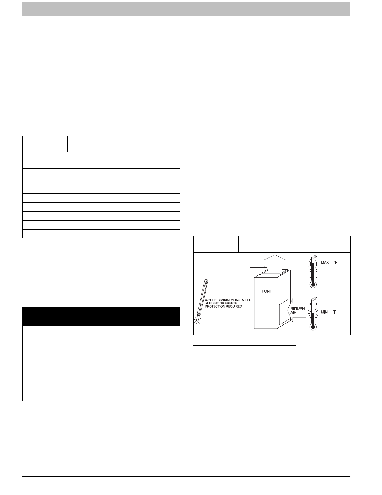
This furnace is designed for minimum continuous return−air
temperature of 60°F (15°C) db or intermittent operation down to
55°F (15°C) db such as when used with a night setback
thermostat. Return−air temperature must not exceed 80°F
(27°C) db. Failure to follow these return−air temperature limits
may affect reliability of heat exchangers, motors, and controls
(See Figure 1)
The furnace should be sized to provide 100 percent of the
design heating load requirement plus any margin that occurs
because of furnace model size capacity increments. None of
the furnace model sizes can be used if the heating load is
12,000 BTU or lower. Use Air Conditioning Contractors of
America (Manual J and S); American Society of Heating,
Refrigerating, and Air−Conditioning Engineers; or other
approved engineering method to calculate heating load
estimates and select the furnace. Excessive oversizing of the
furnace may cause the furnace and/or vent to fail prematurely,
customer discomfort and/or vent freezing.
Failure to follow these guidelines is considered faulty
installation and/or misapplication of the furnace; and resulting
failure, damage, or repairs may impact warranty coverage.
For accessory installation details, refer to the applicable
instruction literature.
NOTE: Remove all shipping materials, parts assemblies and
literature before operating the furnace.
Figure 1
Freeze Protection and Return Air
Temperature
80 / 27˚C
SUPPLY AIR
60
NOTICE
IMPORTANT INSTALLATION AND START−UP
PROCEDURES
Failure to follow this procedure may result in a nuisance
smoke or odor complaint.
The manifold pressure, gas rate by meter clocking,
temperature rise and operation must be checked after
installation. Minor smoke and odor may be present
temporarily after start−up from the manufacturing process.
Some occupants are more sensitive to this minor smoke
and odor. It is recommended that doors and windows be
open during the first heat cycle.
Introduction
The 4−way multipoise Category IV condensing furnace is CSA
design certified as: A direct vent (2−pipe) furnace of 40,000
BTUH through 140,000 BTUH models using outside air for
combustion. The 26,000 BTUH model can use the same
2−pipe venting system using outside air for combustion, but is
not considered direct vent. A non−direct vent (1−pipe) furnace
for all models using indoor air for combustion or from a well
ventilated attic or crawl space, where permitted by local code.
(See Figure 3) The furnace is factory−shipped for use with
natural gas. The furnace can be converted in the field for use
with propane gas when a factory−supplied conversion kit is
4 440 01 4005 05
Specifications subject to change without notice.
SEE PRODUCT DATA FOR
ACCESSORY CONDENSATE
TRAP HEATER AND CONDENSATE
DRAIN LINE PROTECTION.
Codes and Standards
Follow all national and local codes and standards in
addition to these instructions. The installation must comply
with regulations of the serving gas supplier, local building,
heating, plumbing, and other codes. In absence of local codes,
the installation must comply with the national codes listed
below and all authorities having jurisdiction.
In the United States and Canada, follow all codes and
standards for the following:
Safety
S US: Current edition of the National Fuel Gas Code
(NFGC) NFPA 54/ANSI Z223.1 and the Installation
Standards, Warm Air Heating and Air Conditioning
Systems ANSI/NFPA 90B
S A manufactured (Mobile) home installation must
conform with the Manufactured Home Construction
and Safety Standard, Title 24 CFR, Part 3280, or
when this standard is not applicable, the Standard for
Manufactured Home Installation (Manufactured Home
/ 16˚C
A150573
INSTALLATION INSTRUCTIONS Gas Furnace: (F/G)9MXT, (F/G)9MXE
Sites, Communities, and Set-Ups),ANSI/NCS A225.1,
and/or CAN/CSA-Z240, MH Series Mobile Homes.
S CANADA: Current edition of the Standard of Canada,
Natural Gas and Propane Installation Code
(NSCNGPIC) CAN/CSA B149.1
General Installation
S US: Current edition of the NFGC and the NFPA 90B.
For copies, contact the National Fire Protection
Association Inc., Batterymarch Park, Quincy, MA
02269; or for only the NFGC contact the American
Gas Association, 400 N. Capitol, N.W., Washington
DC 20001
S CANADA: Current edition of the NSCNGPIC. For a
copy, contact Standard Sales, CSA International, 178
Rexdale Boulevard, Etobicoke (Toronto), Ontario,
M9W 1R3, Canada.
Combustion and Ventilation Air
S US: Current edition of Section 9.3 of the
NFPA54/ANSI Z223.1, Air for Combustion
and Ventilation
S CANADA: Current edition of Part 8 of the CAN/CSA
B149.1, Venting Systems and Air Supply for
Appliances
Duct Systems
S US and CANADA: Current edition of the Air
Conditioning Contractors Association (ACCA) Manual D,
Sheet Metal and Air Conditioning Contractors National
Association (SMACNA), or American Society of Heating,
Refrigeration, and Air Conditioning Engineers
(ASHRAE).
Acoustical Lining and Fibrous Glass
Duct
S US and CANADA: Current edition of the SMACNA,
NFPA 90B as tested by UL Standard 181 for Class I
Rigid Air Ducts
Gas Piping and Gas Pipe Pressure
Testing
S U.S.A.: Current edition of the NFPA 54/ANSI Z223.1,
NFGC; Chapters 5, 6, 7, and 8 and national plumbing
codes.
S CANADA: Current edition of the CAN/CSA−B149.1,
Parts 4, 5, 6 and 9.
In the state of Massachusetts:
S This product must be installed by a licensed plumber or
gas fitter.
S When flexible connectors are used, the maximum
length shall not exceed 36−in. (914 mm).
S When lever type gas shutoffs are used they shall be
T−handle type.
S The use of copper tubing for gas piping is not
approved by the state of Massachusetts.
Electrical Connections
S U.S.A.: Current edition of the National Electrical Code
(NEC) NFPA 70
S CANADA: Current edition of the Canadian Electrical
Code CSA C22.1
Condensate Drain Connection
US: Current edition of the National Standard Plumbing
Code
Canada: Current edition of the National Plumbing Code of
Canada
IMPORTANT: Gas furnaces manufactured on or after
May 1, 2017 are not permitted to be used in Canada for
heating of buildings or structures under construction.
Electrostatic Discharge (ESD)
Precautions Procedure
!
FURNACE RELIABILITY HAZARD
Failure to follow this caution may result in unit component
damage.
Electrostatic discharge can affect electronic components.
Take precautions during furnace installation and servicing to
protect the furnace electronic control. Precautions will prevent electrostatic discharges from personnel and hand tools
which are held during the procedure. These precautions will
help to avoid exposing the control to electrostatic discharge
by putting the furnace, the control, and the person at the
same electrostatic potential.
1. Disconnect all power to the furnace. Multiple
disconnects may be required. DO NOT TOUCH THE
CONTROL OR ANY WIRE CONNECTED TO THE
CONTROL PRIOR TO DISCHARGING YOUR BODY’S
ELECTROSTATIC CHARGE TO GROUND.
2. Firmly touch the clean, unpainted, metal surface of the
furnace chassis which is close to the control. Tools held
in a person’s hand during grounding will be satisfactorily
discharged.
3. After touching the chassis, you may proceed to service
the control or connecting wires as long as you do nothing
to recharge your body with static electricity (for example;
DO NOT move or shuffle your feet, do not touch
ungrounded objects, etc.).
4. If you touch ungrounded objects (and recharge your
body with static electricity), firmly touch a clean,
unpainted metal surface of the furnace again before
touching control or wires.
5. Use this procedure for installed and uninstalled
(ungrounded) furnaces.
6. Before removing a new control from its container,
discharge your body’s electrostatic charge to ground to
protect the control from damage. If the control is to be
installed in a furnace, follow items 1 through 4 before
bringing the control or yourself in contact with the
furnace. Put all used and new controls into containers
before touching ungrounded objects.
7. An ESD service kit (available from commercial sources)
may also be used to prevent ESD damage.
Accessories
See Specification Sheets for a list of accessories for this
product.
CAUTION
440 01 4005 05 5
Specifications subject to change without notice.
INSTALLATION INSTRUCTIONS Gas Furnace: (F/G)9MXT, (F/G)9MXE
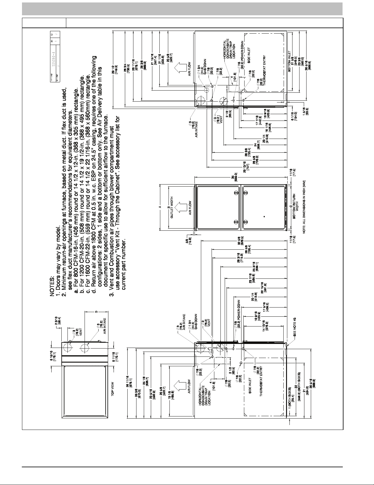
Figure 2 Dimensions
A180202
6 440 01 4005 05
Specifications subject to change without notice.
INSTALLATION INSTRUCTIONS Gas Furnace: (F/G)9MXT, (F/G)9MXE
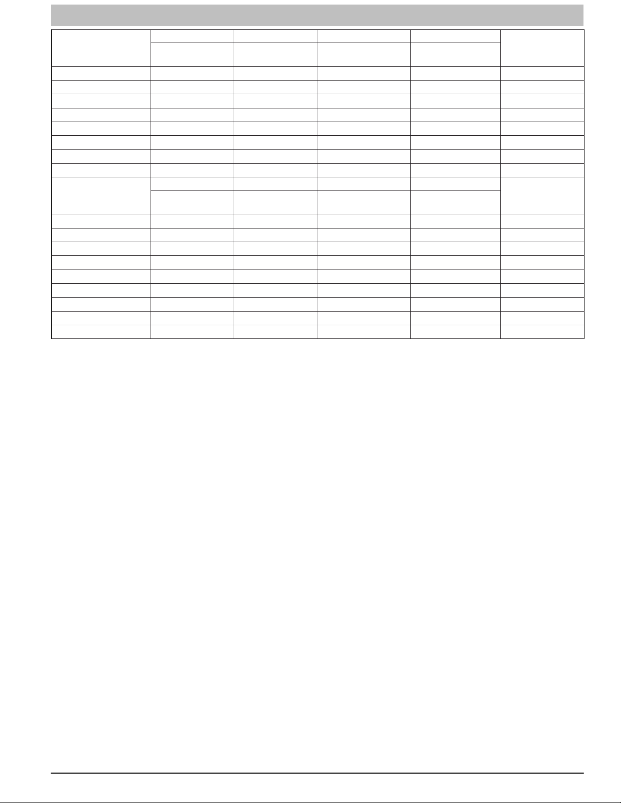
(F/G)9MXT
FURNACE SIZE
0401410 14−3/16 (361) 12−1/2 (319) 12−9/16 (322) 7−1/8 (181) 125 (56)
0401714 17−1/2 (445) 15−7/8 (403) 16 (406) 8−3/4 (222) 135 (61)
0601412 14−3/16 (361) 12−1/2 (319) 12−9/16 (322) 7−1/8 (181) 136 (62)
0601714 17−1/2 (445) 15−7/8 (403) 16 (406) 8−3/4 (222) 146 (66)
0801716 17−1/2 (445) 15−7/8 (403) 16 (406) 8−3/4 (222) 156 (70)
0802120 21 (533) 19−3/8 (492) 19−1/2 (495) 10−1/2 (267) 161 (73)
1002120 21 (533) 19−3/8 (492) 19−1/2 (495) 10−1/2 (267) 171 (77)
1202422 24−1/2 (622) 22−7/8 (581) 23 (584) 12−1/4 (311) 195 (88)
(F/G)9MXE
FURNACE SIZE
0261410 14−3/16 (361) 12−1/2 (319) 12−9/16 (322) 7−1/8 (181) 118 (54)
0401410 14−3/16 (361) 12−1/2 (319) 12−9/16 (322) 7−1/8 (181) 120 (54)
0401714 17−1/2 (445) 15−7/8 (403) 16 (406) 8−3/4 (222) 131 (59)
0601412 14−3/16 (361) 12−1/2 (319) 12−9/16 (322) 7−1/8 (181) 131 (59)
0601714 17−1/2 (445) 15−7/8 (403) 16 (406) 8−3/4 (222) 141 (63)
0801716 17−1/2 (445) 15−7/8 (403) 16 (406) 8−3/4 (222) 151 (68)
0802120 21 (533) 19−3/8 (492) 19−1/2 (495) 10−1/2 (267) 156 (71)
1002120 21 (533) 19−3/8 (492) 19−1/2 (495) 10−1/2 (267) 166 (75)
1202422 24−1/2 (622) 22−7/8 (581) 23 (584) 12−1/4 (311) 190 (85)
CABINET WIDTH OUTLET WIDTH
CABINET WIDTH OUTLET WIDTH
A B C D
BOTTOM
INLET WIDTH
A B C D
BOTTOM
INLET WIDTH
AIR INTAKE
AIR INTAKE
SHIP WT.
LB (KG)
SHIP WT.
LB (KG)
440 01 4005 05 7
Specifications subject to change without notice.
INSTALLATION INSTRUCTIONS Gas Furnace: (F/G)9MXT, (F/G)9MXE
Location
!
PERSONAL INJURY AND/OR PROPERTY DAMAGE
HAZARD
Improper use or installation of this furnace may result in
premature furnace component failure. Unless otherwise
prohibited, this gas furnace may be used for heating
buildings under construction provided that:
−The furnace is permanently installed with all electrical
wiring, piping, venting and ducting installed according to
these installation instructions. A return air duct is
provided, sealed to the furnace casing, and terminated
outside the space containing the furnace. This prevents
a negative pressure condition as created by the
circulating air blower, causing a flame rollout and/or
drawing combustion products into the structure.
−The furnace is controlled by a thermostat. It may not be
“hot wired” to provide heat continuously to the structure
without thermostatic control.
−Clean outside air is provided for combustion. This is to
minimize the corrosive effects of adhesives, sealers and
other construction materials. It also prevents the
entrainment of drywall dust into combustion air, which
can cause fouling and plugging of furnace components.
−The temperature of the return air to the furnace is
maintained between 55°F (13°C) and 80°F (27°C), with
no evening setback or shutdown. The use of the furnace
while the structure is under construction is deemed to be
intermittent operation per our installation instructions.
−The air temperature rise is within the rated rise range on
the furnace rating plate, and the gas input rate has been
set to the nameplate value.
−The filters used to clean the circulating air during the
construction process must be either changed or
thoroughly cleaned prior to occupancy.
−The furnace, ductwork and filters are cleaned as
necessary to remove drywall dust and construction
debris from all HVAC system components after
construction is completed.
−Verify proper furnace operating conditions including
ignition, gas input rate, air temperature rise, and venting
according to these installation instructions.
General
These furnaces are shipped with materials to assist in proper
furnace installation. These materials are shipped in the main
blower compartment.
See Table 2 for loose parts bag contents.
This furnace must:
be installed so the electrical components are protected
from water.
not be installed directly on any combustible material other
than wood flooring (refer to SAFETY
CONSIDERATIONS).
CAUTION
be located close to the chimney or vent and attached to an
air distribution system. Refer to Air Ducts section.
be provided ample space for servicing and cleaning.
Always comply with minimum fire protection clearances
shown in Table 1 or on the furnace clearance to
combustible construction label.
Table 2
QUANTITY DESCRIPTION
1
1 Air Intake Pipe Flange
1 Vent Pipe Flange
2 Pipe Flange Gaskets
10 Sharp Tip Screws (Vent and Inlet Flanges)
1 Vent Pipe Coupling
2 Vent Pipe Coupling Clamps
1 Pressure Switch Tube
1 Rubber Drain Elbow
4 Drain Elbow Clamps
1 1/2”CPVC to 3/4” PVC Pipe Adapter
1 Gas Line Grommet
1 Gas Line Knockout Plug
1 Junction Box Cover
1 Junction Box Base
1 Green Ground Screw
3 Blunt Tip Screws (Junction Box)
1 Thermostat Wire Grommet
Provided separately in furnace
1 Drain Extension Tube − “Z” Pipe
NOTE: The 26K and 40K models are the only furnace that
receives the outlet restrictor in loose parts bag. See Maximum
Equivalent Vent Length Table for usage.
Loose Parts Bag Contents
Outlet Restrictor Plate − see NOTE
(Provided with 26K and 40K BTUH furnaces,
only)
!
WARNING
CARBON MONOXIDE POISONING / COMPONENT
DAMAGE HAZARD
Failure to follow this warning could result in personal injury or death and unit component damage.
Corrosive or contaminated air may cause failure of parts
containing flue gas, which could leak into the living
space. Air for combustion must not be contaminated by
halogen compounds, which include fluoride, chloride,
bromide, and iodide. These elements can corrode heat
exchangers and shorten furnace life. Air contaminants
are found in aerosol sprays, detergents, bleaches, cleaning solvents, salts, air fresheners, and other household
products. Do not install furnace in a corrosive or contaminated atmosphere. Make sure all combustion and circulating air requirements are met, in addition to all local
codes and ordinances.
8 440 01 4005 05
Specifications subject to change without notice.
INSTALLATION INSTRUCTIONS Gas Furnace: (F/G)9MXT, (F/G)9MXE
The following types of furnace installations may require
OUTDOOR AIR for combustion due to chemical exposures:
Commercial buildings
Buildings with indoor pools
Laundry rooms
Hobby or craft rooms, and
Chemical storage areas
If air is exposed to the following substances, it should not be
used for combustion air, and outdoor air may be required for
combustion:
Permanent wave solutions
Chlorinated waxes and cleaners
Chlorine based swimming pool chemicals
Water softening chemicals
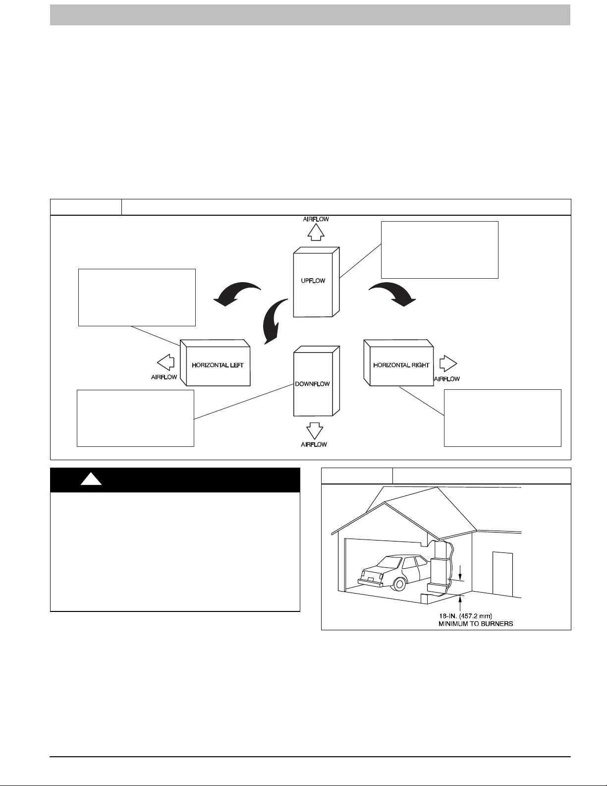
Figure 3 Multipoise Orientations
THE BLOWER IS LOCATED
TO THE RIGHT OF THE
BURNER SECTION, AND
CONDITIONED AIR IS
DISCHARGED TO THE LEFT.
De−icing salts or chemicals
Carbon tetrachloride
Halogen type refrigerants
Cleaning solvents (such as perchloroethylene)
Printing inks, paint removers, varnishes, etc.
Hydrochloric acid
Cements and glues
Antistatic fabric softeners for clothes dryers
Masonry acid washing materials
All fuel−burning equipment must be supplied with air for fuel
combustion. Sufficient air must be provided to avoid negative
pressure in the equipment room or space. A positive seal must
be made between the furnace cabinet and the return−air duct
to prevent pulling air from the burner area.
THE BLOWER IS
LOCATED BELOW THE
BURNER SECTION, AND
CONDITIONED AIR IS
DISCHARGED UPWARD.
THE BLOWER IS
LOCATED ABOVE THE
BURNER SECTION, AND
CONDITIONED AIR IS
DISCHARGED DOWNWARD.
!
WARNING
FIRE, INJURY OR DEATH HAZARD
Failure to follow this warning could result in personal injury,
death and/or property damage.
When the furnace is installed in a residential garage, the
burners and burner ignition devices must be located at least
18−in. (457 mm) above the floor. The furnace must be located
or protected to avoid damage by vehicles. When the furnace is
installed in a public garage, airplane hanger, or other building
having a hazardous atmosphere, the furnace must be installed
in accordance with the current edition of the NFPA 54/ANSI
Z223.1 or CAN/CSA B149.1. (See Figure 4)
THE BLOWER IS
LOCATED TO THE LEFT
OF THE BURNER SECTION,
AND CONDITIONED AIR IS
DISCHARGED TO THE RIGHT.
L12F010
Figure 4 Installation in a Garage
A93044
440 01 4005 05 9
Specifications subject to change without notice.
INSTALLATION INSTRUCTIONS Gas Furnace: (F/G)9MXT, (F/G)9MXE
!
FIRE HAZARD
Failure to follow this warning could result in personal injury,
death and/or property damage.
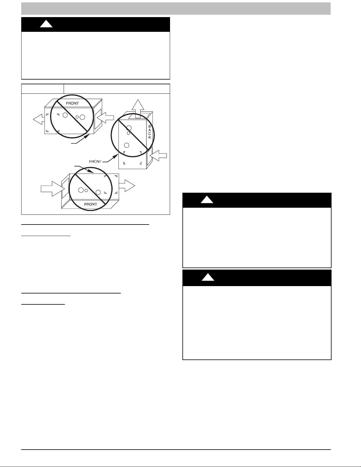
Do not install the furnace on its back or hang furnace with control compartment facing downward. Safety control operation will
be adversely affected. Never connect return−air ducts to the
back of the furnace. (See Figure 5)
WARNING
Figure 5 Prohibit Installations
BACK POSITIONED
DOWNWARD
BACK POSITIONED
UPWARD
AIR
RETURN
CUT IN
BACK
Ventilated Combustion Air Applications
When the furnace is installed using the ventilated combustion
air option, the attic or crawlspace must freely communicate with
the outdoor to provide sufficient air for combustion. The
combustion air pipe cannot be terminated in attics or
crawlspaces that use ventilation fans designed to operate
during the heating season. If ventilation fans are present in
these areas, the combustion air pipe must terminate outdoors
as a Direct Vent/ 2-Pipe system.
All air for combustion is piped directly to the furnace from a
space that is well ventilated with outdoor air (such as an attic,
crawlspace, or equipment closet) and the space is well isolated
from the living space or garage. In addition, other gas
appliances installed in the space with the furnace may require
outside air for combustion. Follow the guidelines below to
insure that the roof or crawlspace walls have sufficient free
area to provide sufficient air for combustion and ventilation for
the furnaces. The guidelines below can be used to insure that
other gas appliances have sufficient air for combustion.
Provisions for adequate combustion, ventilation, and dilution air
must be provided in accordance with:
U.S. Installations: Current edition of Section 9.3 of the
NFPA 54/ANSI Z223.1, Air for Combustion and Ventilation
and applicable provisions of the local building codes.
Canadian Installations: Current edition of Part 8 of
CAN/CSA−B149.1, Venting Systems and Air Supply for
Appliances and all authorities having jurisdiction.
L12F011
Location Relative to Cooling
Equipment
The cooling coil must be installed parallel with, or on the
downstream side of the unit to avoid condensation in the heat
exchangers. When installed parallel with the furnace, dampers
or other flow control must prevent chilled air from entering the
furnace. If the dampers are manually operated, they must be
equipped with means to prevent operation of either unit unless
the damper is in the full−heat or full−cool position.
Air for Combustion and
Ventilation
Introduction
Direct Vent (2−pipe) Applications
When the furnace is installed as a direct vent (2-pipe) furnace,
no special provisions for air for combustion are required.
However, other gas appliances installed in the space with the
furnace may require outside air for combustion. Follow the
guidelines below to insure that other gas appliances have
sufficient air for combustion.
Non−Direct Vent (1−pipe) Applications
When the furnace is installed as a non-direct vent (1-pipe)
furnace, it will be necessary to insure there is adequate air for
combustion. Other gas appliances installed with the furnace
may also require air for combustion and ventilation in addition
to the amount of combustion air and ventilation air required for
the furnace. Follow the guidelines below to insure that the
furnace and other gas appliances have sufficient air for
combustion.
!
FURNACE CORROSION HAZARD
Failure to follow this caution may result in furnace damage.
Air for combustion must not be contaminated by halogen
compounds, which include fluoride, chloride, bromide, and
iodide. These elements can corrode heat exchangers and
shorten furnace life. Air contaminants are found in aerosol
sprays, detergents, bleaches, cleaning solvents, salts, air
fresheners, and other household products.
!
CARBON MONOXIDE POISONING HAZARD
Failure to follow this warning could result in personal injury or
death.
The operation of exhaust fans, kitchen ventilation fans,
clothes dryers, attic exhaust fans or fireplaces could create a
NEGATIVE PRESSURE CONDITION at the furnace.
Make−up air MUST be provided for the ventilation devices, in
addition to that required by the furnace. Refer to the Carbon
Monoxide Poisoning Hazard warning in the venting section of
these instructions to determine if an adequate amount of
make−up air is available.
The requirements for combustion and ventilation air depend
upon whether or not the furnace is located in a space having a
volume of at least 50 cubic feet per 1,000 Btuh (4.8 cubic
meters per kW) input rating for all gas appliances installed in
the space.
Spaces having less than 50 cubic feet per 1,000 Btuh (4.8
cubic meters per kW) require the OUTDOOR
COMBUSTION AIR METHOD.
Spaces having at least 50 cubic feet per 1,000 Btuh (4.8
cubic meters per kW) may use the INDOOR
COMBUSTION AIR, STANDARD or KNOWN AIR
INFILTRATION METHOD.
CAUTION
WARNING
10 440 01 4005 05
Specifications subject to change without notice.
INSTALLATION INSTRUCTIONS Gas Furnace: (F/G)9MXT, (F/G)9MXE
Outdoor Combustion Air Method
1. Provide the space with sufficient air for proper
combustion, ventilation, and dilution of flue gases using
permanent horizontal or vertical duct(s) or opening(s)
directly communicating with the outdoors or spaces that
freely communicate with the outdoors.
2. Figure 6 illustrates how to provide TWO OUTDOOR
OPENINGS, one inlet and one outlet combustion and
ventilation air openings to the outdoors.
appliance in the space and add the volumes together to get the
total minimum required volume for the space.
Table 4 − Minimum Space Volumes were determined by
using the following equations from the current edition of the
National Fuel Gas Code ANSI Z223.1/NFPA 54, 9.3.2.2:
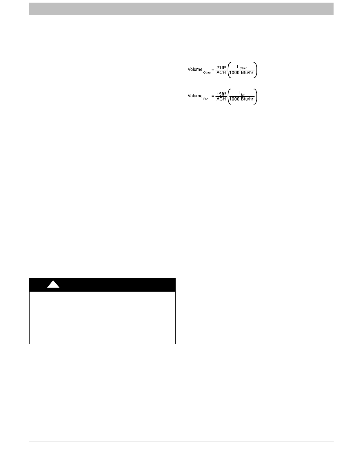
1. For other than fan-assisted appliances, such as a
draft hood-equipped water heater
A04002
a. One opening MUST commence within 12-in.
(300 mm) of the ceiling and the second opening
MUST commence within 12-in. (300 mm) of the floor.
2. For fan-assisted appliances such as this furnace:
A04003
b. Size openings and ducts per Figure 6 and Table 3.
c. TWO HORIZONTAL DUCTS require 1 square inch
(25.4 square mm) of free area per 2,000 Btuh (1,100
2
mm
/kW) of combined input for all gas appliances in
the space per Figure 6 and Table 3.
d. TWO OPENINGS OR VERTICAL DUCTS require 1
square inch (25.4 square mm)of free area per 4,000
Btuh (550 mm
2
/kW) for combined input of all gas
appliances in the space per Figure 6 and Table 3.
3. ONE OUTDOOR OPENING requires:
a. 1 sq. in. (25.4 square mm)of free area per 3,000 Btuh
(734 mm
2
/kW) for combined input of all gas
appliances in the space per Table 3 and
b. Not less than the sum of the areas of all vent
connectors in the space.
The opening shall commence within 12-in. (300 mm) of the
ceiling. Appliances in the space shall have clearances of at
least 1-in. (25 mm) from the sides and back and 6-in. (150 mm)
from the front. The opening shall directly communicate with the
outdoors or shall communicate through a vertical or horizontal
duct to the outdoors or spaces (crawl or attic) that freely
communicate with the outdoors.
Indoor Combustion Air
NFPA & AGA
Standard and Known-Air-Infiltration Rate
Methods
Indoor combustion air is permitted for combustion, ventilation,
and dilution, if the Standard or Known-Air-Infiltration Rate
Method is used.
!
CARBON MONOXIDE POISONING HAZARD
Failure to follow this warning could result in personal injury or
death.
Many homes require air to be supplied from outdoors for
furnace combustion, ventilation, and dilution of flue gases.
The furnace combustion air supply must be provided in
accordance with this instruction manual.
WARNING
If:
I
other=combined input of all other than fan-assisted
appliances in Btuh/hr
fan=combined input of all fan-assisted appliances in Btuh/hr
I
ACH = air changes per hour (ACH shall not exceed 0.60.)
The following requirements apply to the Standard Method and
to the Known Air Infiltration Rate Method.
1. Adjoining rooms can be considered part of a space if:
a. There are no closable doors between rooms.
b. Combining spaces on same floor level. Each opening
shall have free area of at least 1-in.
(2,000 mm
2
/kW) of the total input rating of all gas
2
/1,000 Btuh
appliances in the space, but not less than 100-in.
(0.06 m2). One opening shall commence within 12−in.
(300 mm) of the ceiling and the second opening shall
commence within 12-in. (300 mm) of the floor. The
minimum dimension of air openings shall be at least
3-in. (80 mm). (See Figure 7)
c. Combining space on different floor levels. The
volumes of spaces on different floor levels shall be
considered as communicating spaces if connected by
one or more permanent openings in doors or floors
having free area of at least 2−in.
(4,400 mm
2
/kW) of total input rating of all
2
/1,000 Btuh
gas appliances.
2. An attic or crawlspace may be considered a space that
freely communicates with the outdoors provided there
are adequate permanent ventilation openings directly to
outdoors having free area of at least 1-in.
2
/4,000 Btuh of
total input rating for all gas appliances in the space.
3. In spaces that use the Indoor Combustion Air Method,
infiltration should be adequate to provide air for
combustion, permanent ventilation and dilution of flue
gases. However, in buildings with unusually tight
construction, additional air MUST be provided using
the methods described in the Outdoor Combustion Air
Method section.
4. Unusually tight construction is defined as Construction
with:
The Standard Method:
1. The space has no less volume than 50 cubic feet per
1,000 Btuh (4.8 cubic meters per kW) of the maximum
input ratings for all gas appliances installed in the space
and
2. The air infiltration rate is not known to be less than 0.40
air changes per hour (ACH).
The Known Air Infiltration Rate Method shall be used, if the
infiltration rate is known to be:
1. Less than 0.40 ACH and
a. Walls and ceilings exposed to the outdoors have a
continuous, sealed vapor barrier. Openings are
gasketed or sealed and
b. Doors and openable windows are weatherstripped
and
c. Other openings are caulked or sealed. These include
joints around window and door frames, between sole
plates and floors, between wall-ceiling joints, between
wall panels, at penetrations for plumbing, electrical
and gas lines, etc.
2. Equal to or greater than 0.10 ACH
Infiltration rates greater than 0.60 ACH shall not be used. The
minimum required volume of the space varies with the number
of ACH and shall be determined per Table 4 or Equations 1
and 2. Determine the minimum required volume for each
440 01 4005 05 11
Specifications subject to change without notice.
2

INSTALLATION INSTRUCTIONS Gas Furnace: (F/G)9MXT, (F/G)9MXE
Combination of Indoor and Outdoor Air
1. Indoor openings shall comply with the Indoor
Combustion Air Method below and,
2. Outdoor openings shall be located as required in the
Outdoor Combustion Air Method mentioned previously
and,
3. Outdoor openings shall be sized as follows:
b. Outdoor opening size reduction Factor is one minus
the Ratio in a. above.
c. Minimum size of Outdoor openings shall be the size
required in Outdoor Combustion Air Method above
multiplied by reduction Factor in b. above. The
minimum dimension of air openings shall be not less
than 3-in. (80 mm).
a. Calculate the Ratio of all Indoor Space volume
divided by required volume for Indoor Combustion
Air Method.
Table 3 Minimum Free Area Required for Each Combustion Air Opening or Duct to Outdoors
TWO OPENINGS OR
VERTICAL DUCTS
(1 SQ. IN./4,000 BTUH)
(550 SQ. MM/KW)
Free Area of Open-
ing and Duct
Sq. In (mm)
FURNACE
INPUT
(BTUH)
TWO HORIZONTAL DUCTS
(1 SQ. IN./2,000 BTUH)
(1,100 SQ. MM/KW)
Free Area of
Opening and Duct
Sq. In (Sq. mm)
Round
In. (mm)
Duct
Dia
SINGLE DUCT OR OPENING
(1 SQ. IN./3,000 BTUH)
(734 SQ. MM/KW)
Free Area of Open-
ing and Duct
Sq. In (Sq. mm)
Round
Duct
In. (mm)
Dia
26,000 * 13 (8388) 4 (102) 9 (5807) 4 (102) 7 (4517) 3 (77)
40,000 * 20 (12904) 5 (127) 14 (8696) 5 (127) 10 (6452) 4 (102)
60,000 30 (19355) 6 (152) 20 (13043) 5 (127) 15 (9678) 5 (127)
80,000 40 (25807) 7 (178) 27 (17391) 6 (152) 20 (12904) 5 (127)
100,000 50 (32258) 8 (203) 34 (21739) 7 (178) 25 (16130) 6 (152)
120,000 60 (38709) 9 (229) 40 (26087) 7 (178) 30 (19355) 6 (152)
140,000 * 70 (45161) 10 (254) 47 (30435) 8 (203) 35 (22581) 7 (178)
Round Duct
In. (mm)
Dia.
* Not all families have these models.
EXAMPLE: Determining Free Area
FURNACE WATER HEATER TOTAL INPUT
100,000 + 30,000 = (130,000 divided by 4,000) = 32.5 Sq. In. for each two Vertical Ducts or Openings
60,000 + 40,000 = (100,000 divided by 3,000) = 33.3 Sq. In. for each Single Duct or Opening
80,000 + 30,000 = (110,000 divided by 2,000) = 55.0 Sq. In. for each two Horizontal Ducts
Table 4 Minimum Space Volumes for 100% Combustion, Ventilation and Dilution Air from Outdoors
OTHER THAN FAN‐ASSISTED TOTAL
(1,000'S BTUH GAS INPUT RATE)
ACH
0.60
0.50
0.40
0.30
0.20
0.10
0.00 NP NP NP NP NP NP NP NP NP NP
NP = Not Permitted
30 40 50 26 40 60 80 100 120 140
Space Volume Ft
1,050
(29.7)
1,260
(35.6)
1,575
(44.5)
2,100
(59.4)
3,150
(89.1)
6,300
(178.0)
1,400
(39.6)
1,680
(47.5)
2,100
(59.4)
2,800
(79.2)
4,200
(118.9)
8,400
(237.8)
1,750
(49.5)
2,100
(59.4)
2,625
(74.3)
3,500
(99.1)
5,250
(148.6)
10,500
(297.3)
910
(25.8)
1,092
(30.9)
1,365
(38.7)
1,820
(51.5)
2,730
(77.3)
5,460
(154.6)
1,400
(39.6)
1,680
(47.5)
2,100
(59.4)
2,800
(79.2)
4,200
(118.9)
8,400
(237.8)
FAN‐ASSISTED TOTAL
(1,000'S BTUH GAS INPUT RATE)
3
3
(M
)
1,500
(42.5)
1,800
(51.0)
2,250
(63.7)
3,000
(84.9)
4,500
(127.3)
9,000
(254.6)
2,000
(56.6)
2,400
(67.9)
3,000
(84.9)
4,000
(113.2)
6,000
(169.8)
12,000
(339.5)
2,500
(70.8)
3,000
(84.9)
3,750
(106.1)
5,000
(141.5)
7,500
(212.2)
15,000
(424.4)
3,000
(84.9)
3,600
(101.9)
4,500
(127.3)
6,000
(169.8)
9,000
(254.6)
18,000
(509.2)
3,500
(99.1)
4,200
(118.9)
5,250
(148.6)
7,000
(198.1)
10,500
(297.1)
21,000
(594.1)
12 440 01 4005 05
Specifications subject to change without notice.
INSTALLATION INSTRUCTIONS Gas Furnace: (F/G)9MXT, (F/G)9MXE
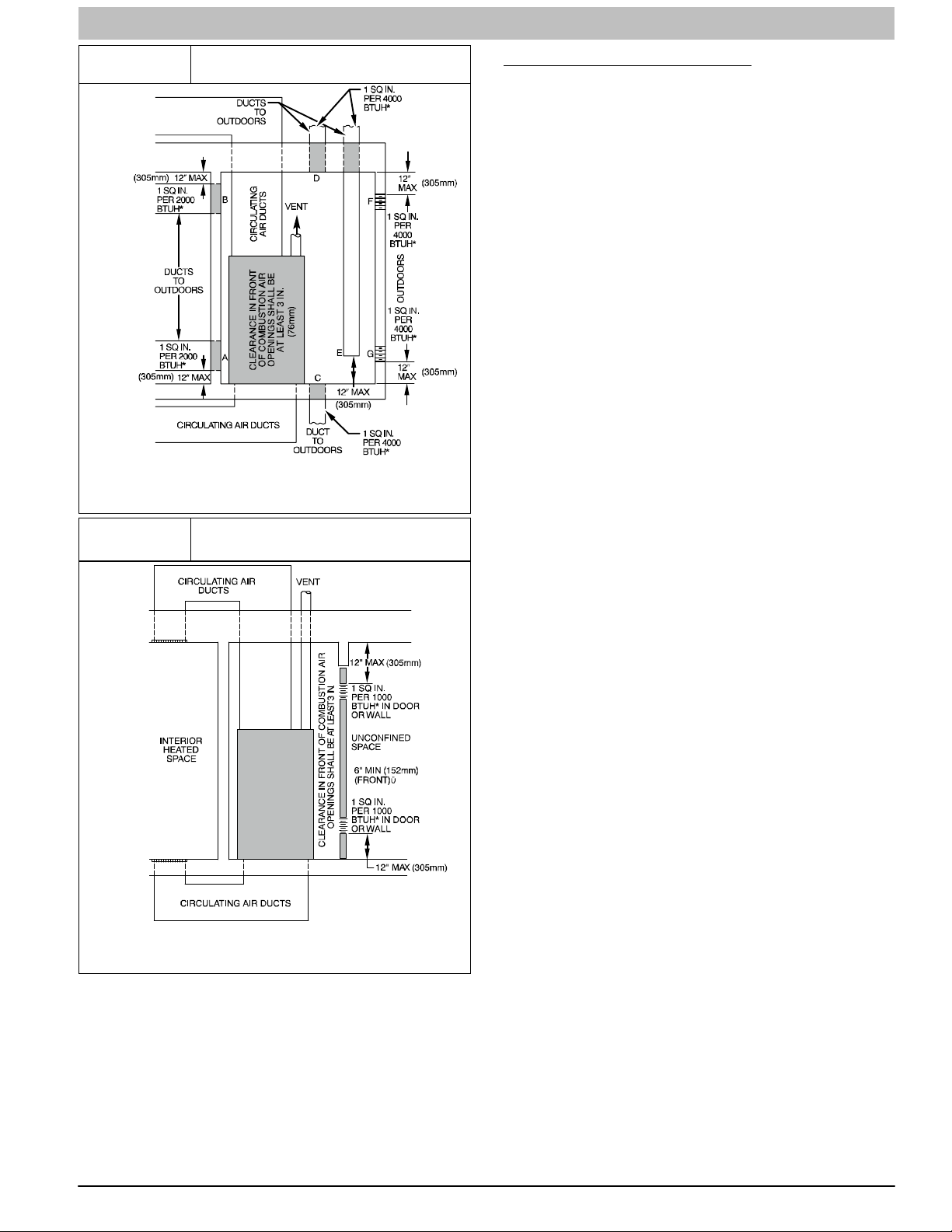
Figure 6
Figure 7
Air for Combustion, Ventilation,
and Dilution for Outdoors
*Minimum dimensions of 3‐in. (76mm)
NOTE: Use any of the following combinations of openings:
A & B, C & D, D & E, F & G
Air for Combustion, Ventilation,
and Dilution from Indoors
CONDENSATE TRAP
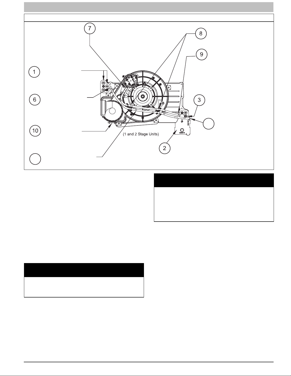
Condensate Trap − Upflow Orientation
When the furnace is installed in the upflow position, it is not
necessary to relocate the condensate trap or associated
tubing. Refer to Figure 8 for upflow condensate trap
information. Refer to Condensate Drain section for information
how to install the condensate drain.
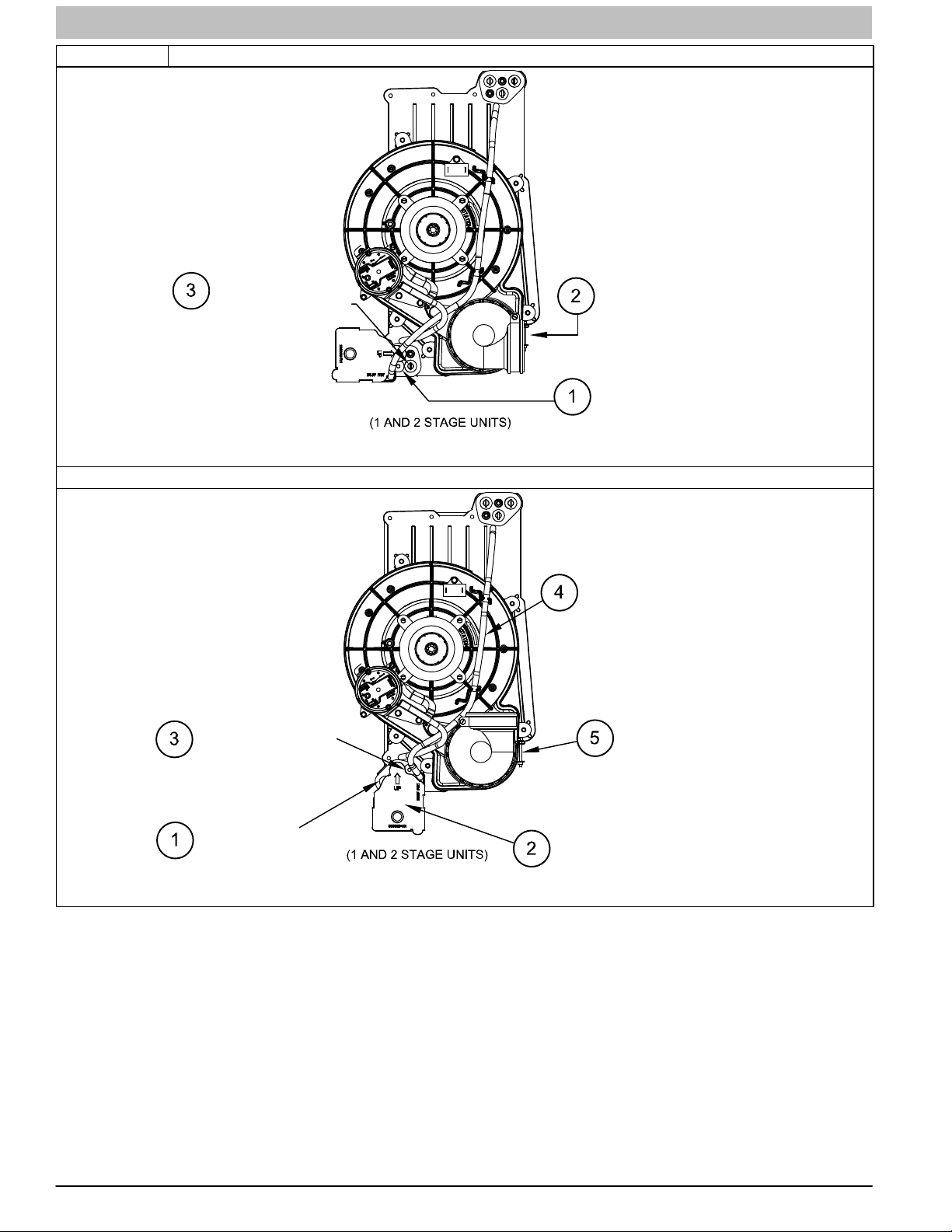
Condensate Trap − Downflow
Orientation
When the furnace is installed in the downflow position, the
condensate trap will be initially located at the upper left corner
of the collector box, as received from the factory. See the top
image in Figure 9. When the furnace is installed in the
downflow orientation, the condensate trap must be relocated
for proper condensate drainage. See the bottom image in
Figure 9.
To Relocate the Condensate Trap:
S Orient the furnace in the downflow position.
S Figure 9 shows the condensate trap and tubing before and
after relocation. Refer to Figure 9 to begin the trap conversion.
S Refer to Condensate Drain section for information how to install
the condensate drain.
L12F012
* Minimum opening size is 100 sq in. (64516 sq. mm) with
minimum dimensions of 3‐in. (76mm)
{ Minimum of 3‐in. (76mm) when type‐B1 vent is used.
440 01 4005 05 13
L12F013
Specifications subject to change without notice.
INSTALLATION INSTRUCTIONS Gas Furnace: (F/G)9MXT, (F/G)9MXE
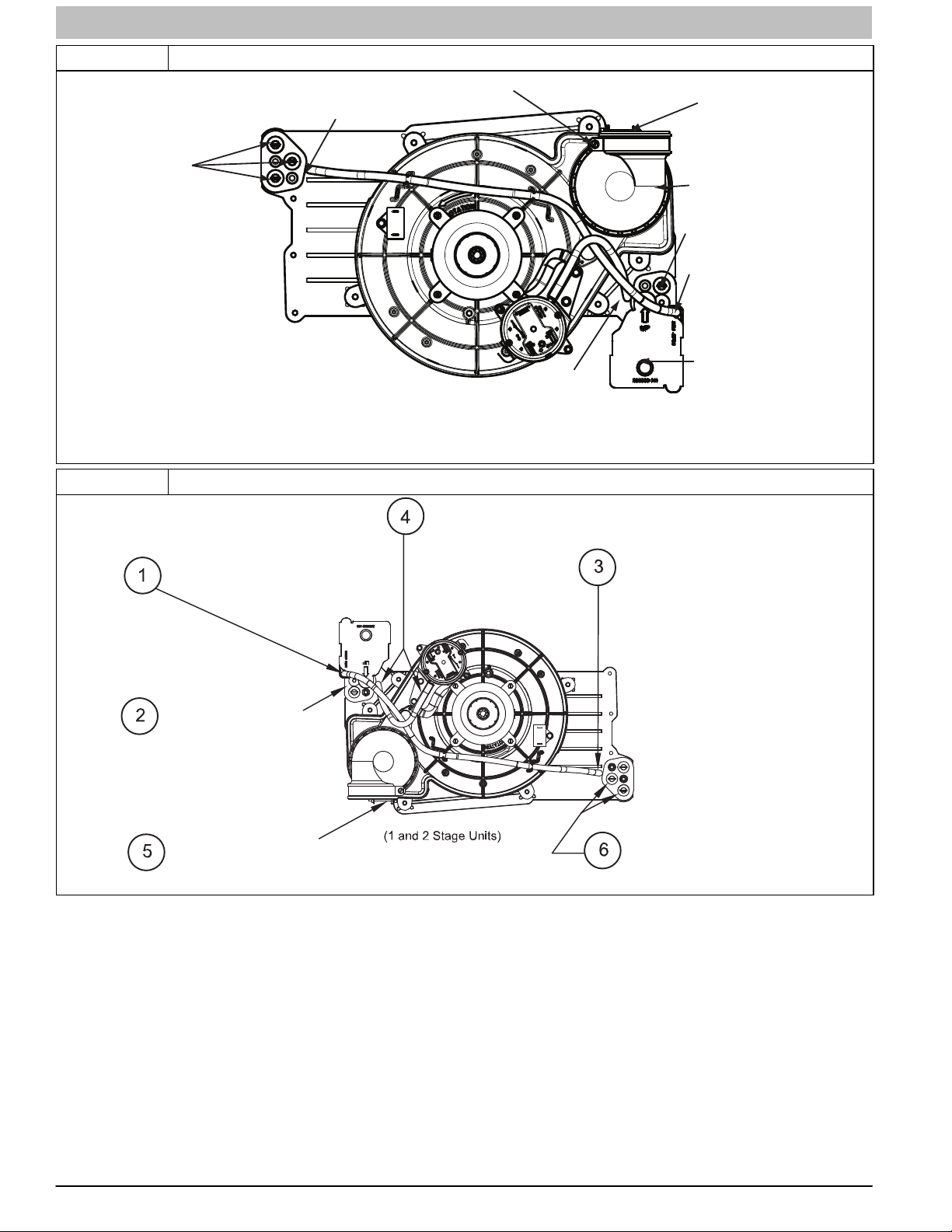
Figure 8 Upflow Trap Configuration
Vent Pipe Clamp
Condensate Trap
Relief Port
Collector Box
Plugs
Pressure Switch
Port
UPFLOW TRAP CONFIGURATION
1 & 2 Stage Units
Representative drawing only, some models may vary in appearance.
Vent Elbow Clamp
Vent Elbow
Collector Box
Plug
Condensate Trap
Relief Port
Condensate Trap
Outlet
A11307
Figure 9 Unconverted Factory Configuration as viewed in the Downflow Orientation
Remove pressure switch tube from
front pressure switch and discard. A
new tube is shipped in the loose parts
Remove relief tube from relief
port on condensate trap.
Remove the screw
that secures the trap
to the collector box and
remove trap.
Loosen clamp on inlet
to vent elbow.
Representative drawing only, some models may vary in appearance.
bag.
Remove tube from relief port.
Remove middle and bottom
plugs. DO NOT DISCARD.
A11587LA
14 440 01 4005 05
Specifications subject to change without notice.
INSTALLATION INSTRUCTIONS Gas Furnace: (F/G)9MXT, (F/G)9MXE
Downflow Trap Configuration
Connect the new pressure switch
tube from Loose Parts bag to
port on front pressure switch.
Install the two plugs
previously removed
on the open ports
of the collector box.
Route tube through inducer
stand−offs to adjust position
of the tube.
Trim excess tube.
Connect pressure switch
tube to port on collector
box.
Connect relief tube
to port on collector
box.
Rotate elbow to
desired position
and
tighten clamp to
15 lb.−in.
Slide tube in stand−offs
4
to adjust length.
Representative drawing only, some models may vary in appearance.
Condensate Trap − Horizontal
Orientation
When the furnace is installed in the horizontal right position, the
condensate trap will be initially located at the bottom of the
collector box, as received from the factory. See the top image in
Figure 10. When the furnace is installed in the horizontal left
position, the condensate trap will be initially located at the top of
the collector box, as received from the factory. See the top image
in Figure 11. In both cases the trap must be repositioned on the
collector box for proper condensate drainage. See bottom images
in Figure 10 and Figure 11.
A field−supplied, accessory Horizontal Installation Kit (trap
grommet) is required for all direct−vent horizontal installations
(only). The kit contains a rubber casing grommet designed to seal
between the furnace casing and the condensate trap. (See
Figure 16)
NOTICE
The field-supplied, accessory horizontal drain trap grommet
is ONLY REQUIRED FOR DIRECT VENT APPLICATIONS. It
is NOT required for applications using single-pipe or ventilated combustion air venting.
Attach condensate trap
with screw to collector box.
Connect relief tube to
5
relief port on condensate
trap.
Align condensate trap
over middle and bottom
ports of collector box.
A11587LB
NOTICE
The condensate trap extends below the side of the casing in
the horizontal position. A minimum of 2-in. (51 mm) of clearance is required between the casing side and the furnace
platform for the trap to extend out of the casing in the horizontal position. Allow at least 1/4-in. per foot (20mm per
meter) of slope down and away from the furnace in horizontal
sections of drain line.
To Relocate the Condensate Trap:
S Remove the knockout in the casing for the condensate trap.
S Install the grommet in the casing when required for direct−vent
horizontal applications.
S Orient the furnace in the desired position.
S Allow for 2 in. (51 mm) of clearance underneath the furnace for
the condensate trap and drain line.
S Figure 10 shows the condensate trap and tubing before and
after relocation in the horizontal right position.
S Figure 11 shows the condensate trap and tubing before and
after relocation in the horizontal left position.
S Refer to the appropriate figure to begin the trap conversion.
S Refer to Condensate Drain section for information how to install
the condensate drain.
440 01 4005 05 15
Specifications subject to change without notice.
INSTALLATION INSTRUCTIONS Gas Furnace: (F/G)9MXT, (F/G)9MXE
Figure 10 Unconverted Factory Configuration as viewed in the Horizontal Right Orientation
Remove plug from
collector box.
DO NOT DISCARD.
Horizontal Right Trap Configuration (continued)
NOTE: Remove knockout in
casing before re−installing the
condensate trap.
Attach condensate
trap with screw to
collector box.
If alternate vent position
is required, loosen clamp
on inlet of vent elbow.
Remove the screw that secures
the trap to the collector box and
remove trap.
Representative drawing only, some models may vary in appearance.
Slide relief tube in stand−offs
to adjust length.
A11573LA
Vent elbow shown in alternate
orientation. Tighten clamp on
inlet to vent elbow 15 lb.−in.
Install plug on
open port of
collector box
Representative drawing only, some models may vary in appearance.
16 440 01 4005 05
Specifications subject to change without notice.
Align trap over middle and
right−hand port on collector box.
A11573LB

INSTALLATION INSTRUCTIONS Gas Furnace: (F/G)9MXT, (F/G)9MXE
Figure 11 Unconverted Factory Configuration as viewed in the Horizontal Left Orientation
Remove the screw that secures the
condensate trap to the collector box
If alternate vent position
5
is required, loosen clamp
on vent elbow inlet.
Remove relief tube
from port on collector
box.
Representative drawing only, some models may vary in appearance.
and remove trap.
Remove relief tube from
relief port on condensate
trap.
Remove middle and right
6
plug from collector box.
DO NOT DISCARD.
Remove front pressure
switch tube and discard.
A new tube is shipped in
the Loose Parts bag.
A11574LA
Horizontal Left Trap Configuration (continued)
NOTE: Remove knockout in
casing before re−installing the
condensate trap.
Rotate elbow to
9
desired position
and torque clamp
on inlet 15 lb.−in.
Install two plugs previously
removed in open ports on
collector box.
Connect relief tube to port
on collector box.
Slide relief tube in
stand−offs to adjust
length.
Attach condensate
trap with screw to
collector box.
Align trap over middle
and right−hand port on
collector box.
Representative drawing only, some models may vary in appearance.
Connect the new pressure switch
7
tube from Loose Parts bag to port
on front pressure switch.
Route pressure switch tube
underneath relief tube and
8
connect to port on
collector box.
Connect relief tube to relief
port on condensate trap.
A11574LB
440 01 4005 05 17
Specifications subject to change without notice.
INSTALLATION INSTRUCTIONS Gas Furnace: (F/G)9MXT, (F/G)9MXE
Condensate Drain Connection
!
FROZEN AND BURST WATER PIPE HAZARD
Failure to protect against the risk of freezing may result in
property damage.
Special precautions MUST be made if installing furnace in an
area which may drop below freezing. This can cause
improper operation or damage to equipment. If furnace
environment has the potential of freezing, the drain trap and
drain line must be protected. The use of accessory drain trap
heaters, electric heat tape and/or RV antifreeze is required
for these installations.
!
PROPERY DAMAGE HAZARD
Failure to follow this caution may result in burst water pipes
and/or property damage.
If a condensate pump is installed, a plugged condensate
drain or a failed pump may cause the furnace to shut down.
Do not leave the home unattended during freezing weather
without turning off water supply and draining water pipes or
otherwise protecting against the risk of frozen pipes.
DO NOT trap the drain line in any other location than at the
condensate drain trap supplied with the furnace. If possible, DO
NOT route the drain line where it may freeze. The drain line
must terminate at an inside drain to prevent freezing of the
condensate and possible property damage.
Special precautions MUST be made if installing furnace in an
area which may drop below 32°F (0°C). This can cause
improper operation or damage to the equipment. If the furnace
environment has the potential of freezing, the drain trap and
drain line must be protected. In areas where the temperature
may be below 32°F (0°C), a Condensate Freeze Protection kit
is required. The kit includes a condensate trap with heat pad
and replaces the factory−installed condensate trap. Refer to the
accessory section of the Specification Sheets for current kit
number. A self−regulating, shielded and waterproof heat tape
rated at 3 to 6 watt per foot (10 to 20 watt per meter) at 115 volt,
40° F (4° C) may be used to provide freeze protection of the
remaining condensate drain line. Wrap the drain trap and the
drain line with the heat tape and secure with appropriate plastic
ties. Follow the heat tape manufacturer’s recommendations.
Prime the trap before furnace operation.
The condensate drain line must be supported and/or secured
per local codes. Supports and clamps should be spaced to
prevent the drain line from sagging or being dislocated from the
furnace or termination point. In the absence of local codes,
consult current edition of the National Standard Plumbing
Code, in the US or current edition of the National Plumbing
Code of Canada in Canada.
CAUTION
CAUTION
c. All condensate piping is at least 1/2 in. PVC and
there is a relief tee at the top of condensate drain
piping as shown below:
NOTE: On narrower casings, it may be easier to remove the
condensate trap, connect the drain line components and
re-install the condensate trap. Read the steps thoroughly to
familiarize yourself with the required steps.
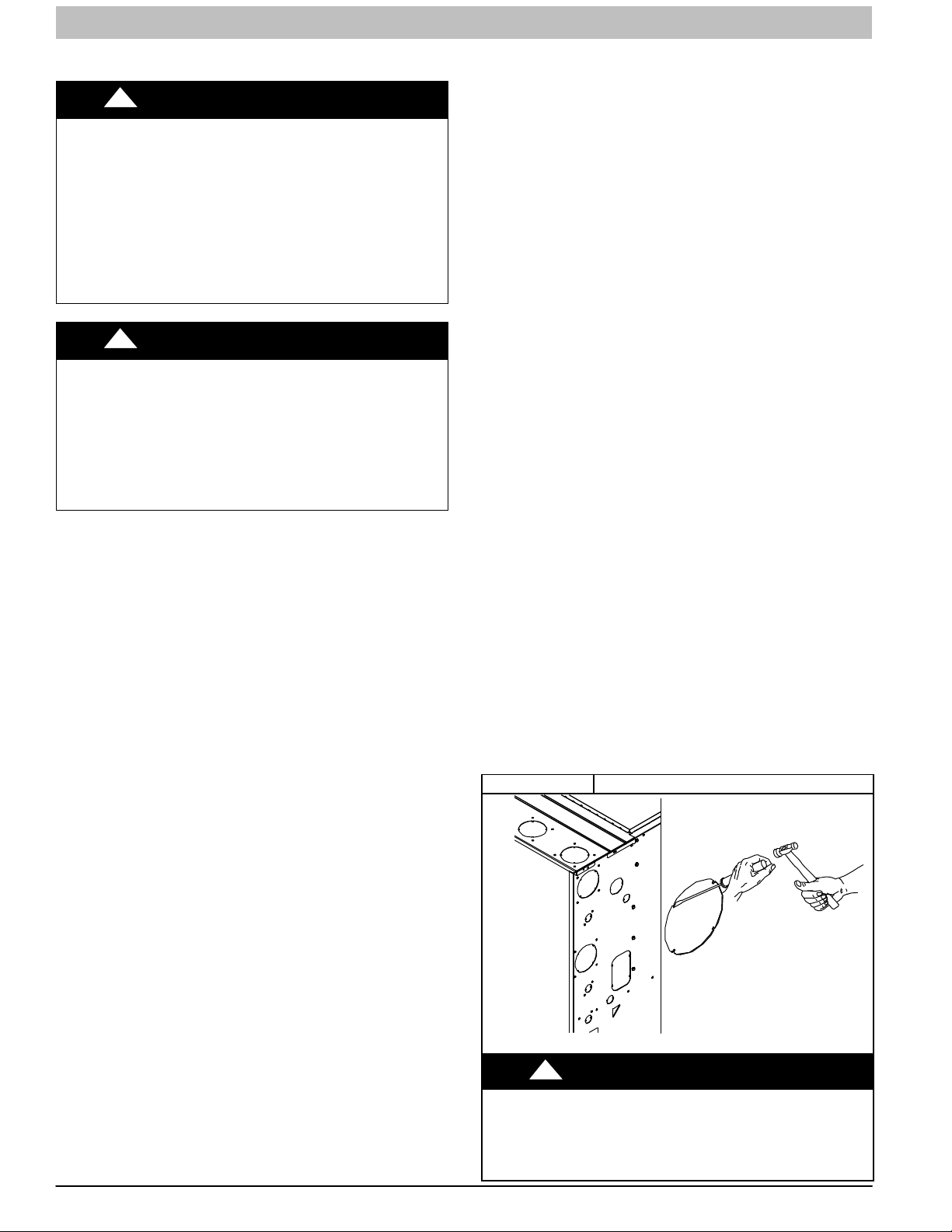
For Right Side Condensate Drain:
1. Remove the 7/8−in. knock−out from the right side of the
casing. (See Figure 12 for suggested knockout removal
technique.)
2. Remove the pre−formed rubber drain elbow and two
spring clamps from the loose parts bag.
3. Slide a spring clamp 1−in. (25 mm) down the plain end
(the end without the formed grommet) of the drain elbow.
4. From inside the casing, insert the formed grommet end
of the elbow through the 7/8−in. knockout in the casing.
5. Pull the grommet through the casing from the outside
until it is seated in the knockout
6. Attach the plain end of the drain elbow to the outlet stub
on the drain trap. Secure the drain elbow to the trap with
the spring clamp.
The remaining drain line can be constructed from field supplied
1/2−in. CPVC or 3/4−in. PVC pipe in compliance with local
building codes. A factory−supplied 1/2−in. CPVC to 3/4−in PVC
adapter is supplied in the loose parts bag for use as required.
7. Install the adapter or connect the 1/2−in. CPVC pipe by
sliding a spring clamp over the open end of the grommet
on the outside of the furnace casing.
8. Open the spring clamp and insert the long end of the
adapter of the 1/2−in. CPVC pipe into the outlet stub on
the drain elbow.
9. Connect additional condensate piping to a
code−approved drain, or to a condensate pump
approved for use with acidic furnace condensate and
compatible with mineral and vegetable oils, such as
canola oil.
Allow at least 1/4−in. per foot (20 mm per meter) of slope down
and away from the furnace in horizontal sections of drain line.
TIPS FROM CONTRACTORS: Contractors have found that
temporarily removing the inducer assembly in upflow
applications while performing the steps below, makes upflow
left−side drain connections easier.
Figure 12 Knockout Removal
Upflow/Downflow Orientation
In the Upflow or Downflow orientation, the condensate trap is
inside the furnace casing. The condensate drain must be
routed from the trap through the furnace casing. The
condensate drain can be routed through the left or right side of
the casing. (The left or right side is as you are viewing/facing
the furnace from the front.)
An indoor coil condensate drain or humidifier drain can be
connected to the external furnace condensate drain provided:
a. The drains are not hard piped together, and
b. There is an air gap at the point where the two drain
lines meet or
18 440 01 4005 05
Specifications subject to change without notice.
CUT HAZARD
Failure to follow this caution may result in personal injury.
Sheet metal parts may have sharp edges or burrs. Use care
and wear appropriate protective clothing, safety glasses and
gloves when handling parts, and servicing furnaces.
!
CAUTION
L12F019

INSTALLATION INSTRUCTIONS Gas Furnace: (F/G)9MXT, (F/G)9MXE
For Left Side Condensate Drain Connection:
1. For left side condensate drainage, the drain line is routed
from the condensate trap, behind the inducer (upflow) or
gas valve (downflow) and out through the left side of the
furnace casing. A pre-formed 1/2−in. CPVC “Z” pipe is
provided with the furnace. The “Z“ pipe is long enough to
extend across the casing for drain connections.
2. Locate the “Z” pipe. Remove the pre-formed drain elbow
and four spring clamps from the loose parts bag.
3. The “Z” pipe is connected to the condensate trap and the
outside of the furnace by modifying the formed rubber
drain elbow as shown in Figure 17.
4. Remove the formed grommet from the rubber drain
elbow by cutting the elbow along the vertical line located
about 1 3/8−in. (35 mm) away from the formed grommet.
See Figure 15. DO NOT DISCARD THE FORMED
GROMMET OR THE RUBBER ELBOW. Both of these
pieces will be used.
Assemble and route the drain line to the opposite side of the
furnace as detailed below:
5. Remove the knock−out from the left side of the casing.
(See Figure 12 for suggested knockout removal
technique.)
6. From the outside of the casing, insert the angled end of
the ”Z” pipe through drain hole in the left side of the
casing and behind the inducer or gas valve. Allow the ”Z”
pipe to temporarily rest on the blower shelf (upflow) or
burner box (downflow). (NOTE: When the inducer
housing has been removed to ease installation in upflow
applications, this step is not needed.)
7. After inserting the “Z” pipe through the casing, slide a
spring clamp over each end of the “Z” pipe.
8. From inside the casing, insert the short end of the formed
grommet cut from the rubber drain elbow through the
7/8−in. drain knockout in the casing.
9. Pull the grommet through the casing from the outside
until it is seated in the knockout.
10. Align the ”Z” pipe with the long end of the grommet inside
the furnace and insert slightly. The angled end of the
tube at the other side of the casing should be facing the
front of the furnace.
11. Slide a spring clamp over the end of the remaining
rubber drain elbow.
12. Attach the drain elbow to the angled end of ”Z” pipe and
the drain trap outlet stub. Adjust the length of ”Z” pipe
inserted into the grommet at the opposite side of the
furnace as necessary for proper fit and positioning. In
both upflow and downflow orientations, the ”Z” pipe
should NOT be resting on any sheet metal parts.
13. Secure the rubber elbow to the drain trap and the ”Z”
pipe with spring clamps.
14. Secure the grommet to the ”Z” pipe with the spring
clamp. The remaining drain line can be constructed from
field supplied 1/2−in. CPVC or 3/4−in. PVC pipe, in
compliance with local building codes. A factory−supplied
1/2−in. CPVC to 3/4−in. PVC adapter is supplied in the
loose parts bag for use as required.
15. Install the adapter or connect the 1/2−in. CPVC pipe by
sliding a spring clamp over the open end of the grommet
on the outside the furnace casing.
16. Open the spring clamp and insert the long end of the
adapter or the 1/2−in. CPVC pipe into the outlet stub on
the drain elbow.
17. Connect additional condensate piping to a
code−approved drain, or to a condensate pump
approved for use with acidic furnace condensate and
compatible with mineral and vegetable oils, such as
canola oil.
Allow at least 1/4-in. per foot (20 mm per meter) of slope down
and away from the furnace in horizontal sections of drain line.
NOTICE
The field-supplied, accessory horizontal drain trap grommet
is ONLY REQUIRED FOR DIRECT VENT APPLICATIONS. It
is NOT required for applications using single-pipe or ventilated combustion air venting.
TIPS FROM CONTRACTORS: When installing the furnace
horizontally, use the entire drain elbow (that is, do NOT cut as
shown in Figure 15) to connect the trap to the drain line. This
helps to prevent bumps and shocks to the drain line from
damaging the furnace drain trap. Avoid misalignment of the
drain pipe which may cause kinks in the elbow.
Horizontal Orientation
1. The condensate trap outlet extends 2−in. (51 mm) below
the furnace casing. Leave enough clearance between
the furnace and the furnace platform for the trap.
2. To allow for servicing the trap, the condensate drain
elbow in the loose parts bag can be used to make a
coupler to allow for future service of the condensate trap
and drain line.
3. Remove the knock−out for the condensate trap in the
side of the casing.
4. Install the drain trap grommet in the casing, if required for
direct−vent applications. If necessary, remove the trap,
install the grommet and re−install the trap.
5. Remove the pre−formed rubber drain elbow and two
spring clamps from the loose parts bag.
6. Connect the full or modified elbow and/or grommet to the
outlet of the condensate trap with one spring clamp.
Avoid misalignment of the drain pipe which may cause
kinks in the elbow or grommet.
7. The remaining drain line can be constructed from field
supplied 1/2−in. CPVC or 3/4−in. PVC pipe, in
compliance with local building codes. A factory−supplied
1/2−in. CPVC to 3/4−in. PVC adapter is supplied in the
loose parts bag for use as required.
8. Install the adapter or connect the 1/2−in. CPVC pipe by
sliding a spring clamp over the open end of the elbow or
grommet on the outside the furnace casing.
9. Open the spring clamp and insert the long end of the
adapter or the 1/2−in. CPVC pipe into the outlet stub on
the drain elbow.
10. Connect additional condensate piping to a
code−approved drain, or to a condensate pump
approved for use with acidic furnace condensate and
compatible with mineral and vegetable oils, such as
canola oil.
Allow at least 1/4-in. per foot (20 mm per meter) of slope down
and away from the furnace in horizontal sections of drain line.
440 01 4005 05 19
Specifications subject to change without notice.
INSTALLATION INSTRUCTIONS Gas Furnace: (F/G)9MXT, (F/G)9MXE
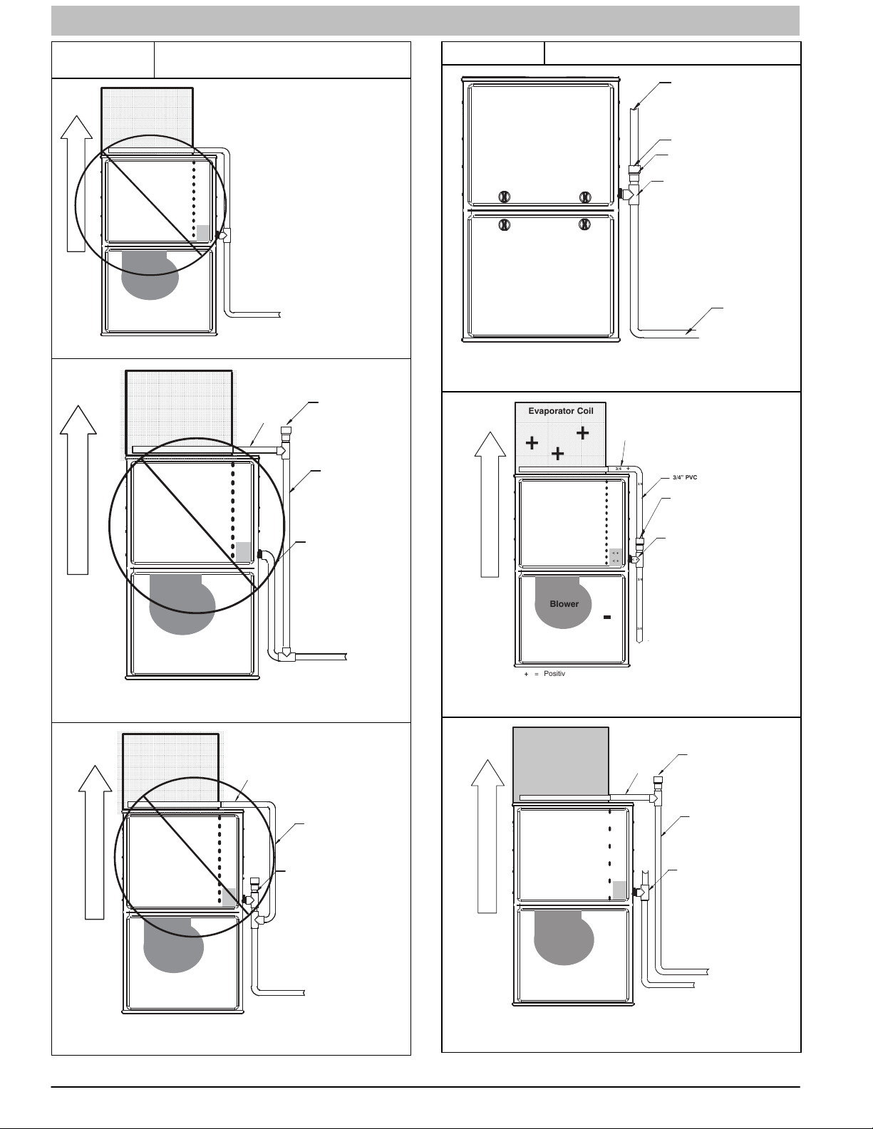
Figure 13
AIRFLOW
OF
DIRECTION
AIRFLOW
OF
DIRECTION
Example of Field Drain Attachment
(NOT ALLOWED)
Evaporator Coil
+
Condensing
Furnace
+
Blower
-
-
Evaporator Coil
+
Condensing
Furnace
+
+
+
+
+
+
+
+
+
< +
< +
< +
+
-
+
-
+
-
+
+
+
+
+
-
+
-
Blower
-
-
-
-
+ = Positive pressure
< + = Pressure lower than areas with +
− = Negative pressure
-
+ = Positive pressure
< + = Pressure lower than areas with +
− = Negative pressure
Blower creates positive pressure.
Positive pressure extends into coil
condensate drain (no trap).
Furnace condensate does not flow
consistently when drain is at positive
pressure.
+
A14532A
Open
+
+
3/4
+
3/4
+
3/4
+
+
standpipe
3/4” PVC
1/2” CPVC or larger*
3/4
A14532B
3/4
< +
< +
3/4” PVC
+
< +
+
1/2
1/2
Figure 14 Example of Field Drain Attachment
&RLORUKXPLGLILHUGUDLQ
ZKHQXVHG
Air gap here
Open standpipeLQKLJK
Evaporator Coil
+
Condensing
Furnace
+
Blower
-
+
+
+
AIRFLOW
OF
+
DIRECTION
-
-
+ = Positive pressure
< + = Pressure lower than areas with +
ï = Negative pressure
PLQLPXP for coilor
humidifier drain
TEE
(1/2” CPVC to 3/4” PVC
adapter from loose parts bag.)
3/4” PVC
3/4
+
+
+
3/4” PVC
3/4
+
Open standpipeLQKLJKPLQLPXP
Air gap required when
+
another drain is connected
+
to furnace drain.
3/4
TEE
< +
3/4
(1/2” CPVC to 3/4” PVC
adapter from loose parts bag.)
< +
< +
-
-
3/4
-
To open drain
A170136
A170139
Evaporator Coil
+
AIRFLOW
OF
DIRECTION
Condensing
+
-
+ = Positive pressure
< + = Pressure lower than areas with +
− = Negative pressure
20 440 01 4005 05
+
Furnace
+
Blower
-
+
+
-
3/4” PVC
3/4
+
+
+
+
3/4” PVC
3/4
+
+
3/4
1/2” CPVC or larger*
+
< +
+
+
+
3/4
+
+
+
3/4
+
3/4
++
A14532C
Specifications subject to change without notice.
< +
< +
-
-
-
Evaporator Coil
+
+
Condensing
Furnace
+
DIRECTION OF AIRFLOW
+
Blower
ï
ï
= Positive pressure
+
< +
= Pressure lower than areas with +
( = Negative pressure
ï
+
+
ï
ï
ï
3/4
+
< +
< + < +
3/4” PVC
+
+
+
3/4
+
+
3/4
3/4
standpipe
Open
(Optional
when coil drain
not
drain.)
3/4” PVC
1/2” CPVC or larger*
Recommend “T” fitting
with minimum 4ïinch
open standpipe of same
diameter or larger extending upward
3/4
connected to
furnace
is
A170129

INSTALLATION INSTRUCTIONS Gas Furnace: (F/G)9MXT, (F/G)9MXE
Example of Field Drain Attachment cont.
Evaporator Coil
3/4
3/4
3/4
< +
3/4
Open standpipe
(Optional when coil drain is
not connected to furnace
drain.)
3/4” PVC
TEE
(1/2” CPVC to 3/4” PVC
adapter from loose parts bag.)
+
+
Condensing
AIRFLOW
OF
DIRECTION
Furnace
+
+
+
+
3/4” PVC
3/4
+
< +
< +
+
-
Blower
-
-
-
-
+ = Positive pressure
< + = Pressure lower than areas with +
ï = Negative pressure
-
Figure 15 Modify Rubber Drain Elbow
Cut line for left side condensate drain.
Do not discard parts after cutting.
3/4
L14F027
Figure 17 Drain Trap Connection and Routing
FORMED END
OF GROMMET
CONNECT SHORT END OF
’Z’ PIPE TO MODIFIED
DRAIN ELBOW
FACTORY SUPPLIED
1/2−IN. CPVC TO 3/4−IN.
PVC ADAPTER
DRAIN ELBOW “Z” DISCHARGE PIPE FOR LEFT SIDE
DRAIN IS ROUTED BEHIND INDUCER
FORMED END OF GROMMET. OPEN
SPRING CLAMP, INSERT 1/2−IN. TO 3/4−IN.
CPVC TO PVC ADAPTER OR CPVC PIPE
MODIFIED DRAIN ELBOW CONNECT TO CONDENSATE TRAP
AND ’Z’ PIPE
LEFT SIDE DRAIN PIPE ORIENTATION FOR CONDENSATE DISCHARGE
NOTE: Remove Inducer Housing for easier access, if desired.
CUT OFF FORMED END
FROM CONDENSATE
DRAIN ELBOW
TOP VIEW
FRONT VIEW
ATTACH ELBOW TO
CONDENSATE TRAP
A170128
1−3/8 in
(35 mm)
L11F089
Figure 16 Horizontal Drain Trap Grommet
Remove knockout.
Install grommet before
relocating condensate
trap.
A11348
Figure 18 Formed Rubber Drain Grommet
INSTALL CLAMPS ON DRAIN ELBOW
ATTACH DRAIN ELBOW TO CONDENSATE
DRAIN TRAP
PULL DRAIN STUB
THROUGH CASING
OPEN SPRING CLAMP
INSERT FACTORY−SUPPLIED 1/2−IN. CPVC
TO 3/4−IN. PVC ADAPTER OR 1/2−IN. CPVC PIPE
*CLAMP MAY BE LOCATED ON OUTSIDE OF DRAIN ELBOW
INSTALLATION
NOTICE
L12F022
Cabinet air leakage is less than 2% at 1.0 in. W.C. Cabinet
air leakage is less than 1.4% at 0.5 in. W.C. when tested in
accordance with ASHRAE Standard 193.
440 01 4005 05 21
Specifications subject to change without notice.

INSTALLATION INSTRUCTIONS Gas Furnace: (F/G)9MXT, (F/G)9MXE
UPFLOW INSTALLATION
NOTE: The furnace must be pitched as shown in Figure 19 for
proper condensate drainage.
Figure 19 Furnace Pitch Requirements
LEVEL 0-IN. (0 MM) TO
1/2-IN. (13 MM) MAX
MIN 1/4-IN. (6 MM) TO
1/2-IN. (13 MM) MAX
UPFLOW OR
DOWNFLOW
HORIZONTAL
A11237
Supply Air Connections
For a furnace not equipped with a cooling coil, the outlet duct
shall be provided with a removable access panel. This opening
shall be accessible when the furnace is installed and shall be of
such a size that the heat exchanger can be viewed for possible
openings using light assistance or a probe can be inserted for
sampling the air stream. The cover attachment shall prevent
leaks.
Connect supply−air duct to flanges on furnace supply−air
outlet. Bend flange upward to 90_ with wide duct pliers. (See
Figure 24) The supply−air duct must be connected to ONLY
the furnace supply−outlet−air duct flanges or air conditioning
coil casing (when used). DO NOT cut main furnace casing side
to attach supply air duct, humidifier, or other accessories. All
supply−side accessories MUST be connected to duct external
to furnace main casing.
Return Air Connections
Figure 20 Removing Bottom Closure Panel
BOTTOM
SCREWS (2)
Representative drawing only,
some models may vary in appearance.
1. Lay furnace on the back or side
2. Remove the two (2) screws that secure the bottom
closure panel to the furnace casing and remove the
panel
Figure 21
Removing Bottom Plate and
Closure Panel
CLOSURE
A170123
!
FIRE HAZARD
A failure to follow this warning could cause personal injury,
death and/or property damage.
Never connect return−air ducts to the back of the furnace.
Follow instructions below.
The return−air duct must be connected to bottom, sides (left or
right), or a combination of bottom and side(s) of main furnace
casing. Bypass humidifier may be attached into unused return
air side of the furnace casing. (See Figure 29, Figure 30, and
Figure 31)
WARNING
Bottom Return Air Inlet
These furnaces are shipped with bottom closure panel installed
in bottom return−air opening. Remove and discard this panel
when bottom return air is used. To remove bottom closure
panel, see Figure 21 and Figure 20.
SCREWS (4)
BOTTOM
PLATE
Representative drawing only,
some models may vary in appearance.
1. Lay furnace on the back or side
2. Remove the four (4) screws that secure the bottom
plate to the furnace casing
3. Remove the bottom closure from the casing
4. Re−install the bottom plate to the furnace casing and
re−install the four (4) screws
A170124
Side Return Air Inlet
These furnaces are shipped with bottom closure panel installed
in bottom return−air opening. This panel MUST be in place
when only side return air is used. Where required by code, seal
bottom closure to furnace with tape, mastic or other durable
sealing method.
NOTE: Side return−air openings can be used in UPFLOW and
most HORIZONTAL configurations. Do not use side return−air
openings in DOWNFLOW configuration. (See Figure 29,
Figure 30, and Figure 31)
22 440 01 4005 05
Specifications subject to change without notice.

INSTALLATION INSTRUCTIONS Gas Furnace: (F/G)9MXT, (F/G)9MXE
Leveling Legs (If Desired)
In upflow position with side return inlet(s), leveling legs may be
used. (See Figure 22) Install field−supplied, 5/16 x 1−1/2−in. (8
x 38 mm) (max) corrosion−resistant machine bolts, washers
and nuts.
Figure 22 Leveling Legs
A89014
NOTE: Bottom closure must be used when leveling legs are
used. It may be necessary to remove and reinstall bottom
closure panel to install leveling legs. To remove bottom closure
panel, see Figure 21 and Figure 20.
To install leveling legs:
1. Position furnace on its back. Locate and drill a hole in
each bottom corner of furnace.
2. For each leg, install nut on bolt and then install bolt with
nut in hole. (Install flat washer if desired.)
3. Install another nut on other side of furnace base. (Install
flat washer if desired.)
4. Adjust outside nut to provide desired height, and tighten
inside nut to secure arrangement.
5. Reinstall bottom closure panel if removed.
DOWNFLOW INSTALLATION
NOTE: The furnace must be pitched as shown in Figure 19 for
proper condensate drainage.
Supply Air Connections
NOTE: For downflow applications, this furnace is approved for
use on combustible flooring when any one of the following two
accessories are used (see specification sheets for list of
approved accessories):
Special Base − NAHA01101SB
Cased Coil Assembly − EAM4X, END4X, ENW4X,
EAD4X
1. Determine application being installed from Table 5.
2. Construct hole in floor per Table 5 and Figure 23.
3. Construct plenum to dimensions specified in Table 5
and Figure 23.
4. Install as shown in Figure 25. If Coil Assembly Part is
used, install as shown in Figure 26 .
Figure 23
NOTE: It is recommended that the perforated supply−air duct
flanges be completely removed from furnace when installing
the furnace on a factory−supplied cased coil or coil box. To
remove the supply−air duct flange, use wide duct pliers or hand
seamers to bend flange back and forth until it breaks off. Be
careful of sharp edges. (See Figure 24)
!
CUT HAZARD
Failure to follow this caution may result in personal injury.
Sheet metal parts may have sharp edges or burrs. Use care
and wear appropriate protective clothing, safety glasses and
gloves when handling parts, and servicing furnaces.
Connect supply−air duct to supply−air outlet on furnace. Bend
flange inward past 90_ with wide duct pliers (See Table 1
Figure 24) The supply−air duct must be connected to ONLY
the furnace supply outlet or air conditioning coil casing (when
used). When installed on combustible material, supply−air duct
must be connected to ONLY the factory−approved accessory
subbase, or a factory−approved air conditioning coil casing. DO
NOT cut main furnace casing to attach supply air duct,
humidifier, or other accessories. All supply−side accessories
MUST be connected to duct external to furnace casing.
Floor and Plenum Opening
Dimensions
A96283
CAUTION
Return Air Connections
!
FIRE HAZARD
A failure to follow this warning could cause personal injury,
death and/or property damage.
Never connect return−air ducts to the back of the furnace.
Follow instructions below.
The return−air duct must be connected to return−air opening
(bottom inlet) as shown in Figure 29. DO NOT cut into casing
sides (left or right). Bypass humidifier connections should be
made at ductwork or coil casing sides exterior to furnace. (See
Figure 29)
WARNING
Bottom Return Air Inlet
These furnaces are shipped with bottom closure panel installed
in bottom return−air opening. Remove and discard this panel
440 01 4005 05 23
Specifications subject to change without notice.

INSTALLATION INSTRUCTIONS Gas Furnace: (F/G)9MXT, (F/G)9MXE
when bottom return air is used. To remove bottom closure
panel, see Figure 21 and Figure 20.
HORIZONTAL INSTALLATION
NOTE: The furnace must be pitched forward as shown in
Figure 19 for proper condensate drainage.
!
FIRE, EXPLOSION, AND CARBON MONOXIDE
POISONING HAZARD
Failure to follow this warning could result in personal
injury, death, or property damage.
Do not install the furnace on its back or hang furnace with
control compartment facing downward. Safety control
operation will be adversely affected. Never connect
return−air ducts to the back of the furnace.
!
MINOR PROPERTY HAZARD
Failure to follow this caution may result in minor property
damage.
Local codes may require a drain pan under entire furnace
and condensate trap when a condensing furnace is used in
an attic application or over a finished ceiling.
WARNING
CAUTION
The furnace can be installed horizontally in an attic or
crawlspace on either the left−hand (LH) or right−hand (RH)
side. The furnace can be hung from floor joists, rafters or
trusses or installed on a non−combustible platform, blocks,
bricks or pad.
Suspended Furnace Support
The furnace may be supported under the entire length of the
furnace with threaded rod and angle iron. (See Figure 27)
Secure angle iron to bottom of furnace as shown.
Platform Furnace Support
Construct working platform at location where all required
furnace clearances are met. (See Table 1 and Figure 28) For
furnaces with 1−in. (25 mm) clearance requirement on side, set
furnace on non−combustible blocks, bricks or angle iron. For
crawlspace installations, if the furnace is not suspended from
the floor joists, the ground underneath furnace must be level
and the furnace set on blocks or bricks.
Figure 24 Duct Flanges
PERFORATED
DISCHARGE DUCT
FLANGE
UPFLOW DOWNFLOW HORIZONTAL
120°
MIN
90°
YES
YES
NO
120°
MIN
YES
YES
NO
120°
MIN
90°
YES
YES
NO
A10493
24 440 01 4005 05
Specifications subject to change without notice.

INSTALLATION INSTRUCTIONS Gas Furnace: (F/G)9MXT, (F/G)9MXE
Table 5 Opening Dimensions − in. (mm)
FURNACE
CASING WIDTH
IN. (mm)
14–3/16
(360)
17–1/2
(445)
21
(533)
24−1/2
(622)
APPLICATION
Upflow Applications on Combustible or Noncombustible Flooring
(subbase not required)
Downflow Applications on Noncombustible Flooring
(subbase not required)
Downflow applications on combustible flooring (subbase required)
Downflow Applications on Combustible Flooring with Coil Assembly or
coil box (subbase not required)
Upflow Applications on Combustible or Noncombustible Flooring
(subbase not required)
Downflow Applications on Noncombustible Flooring
(subbase not required)
Downflow applications on combustible flooring (subbase required)
Downflow Applications on Combustible Flooring with Coil Assembly or coil
box (subbase not required)
Upflow Applications on Combustible or Noncombustible Flooring
(subbase not required)
Downflow Applications on Noncombustible Flooring
(subbase not required)
Downflow applications on combustible flooring
(subbase required)
Downflow Applications on Combustible Flooring with Coil Assembly or coil
box (subbase not required)
Upflow Applications on Combustible or Noncombustible Flooring
(subbase not required)
Downflow Applications on Noncombustible Flooring
(subbase not required)
Downflow applications on Combustible flooring
(subbase required)
Downflow Applications on Combustible Flooring with Coil Assembly or
coil box (subbase not required)
PLENUM OPENING FLOOR OPENING
A B C D
12−11/16
(322)
12−9/16
(319)
11−13/16
(284)
12−5/16
(319)
16
(406)
15−7/8
(403)
15−1/8
(384)
15−1/2
(394)
19−1/2
(495)
19−3/8
(492)
18−5/8
(473)
19
(483)
23
(584)
22−7/8
(581)
22−1/8
(562)
22−1/2
(572)
21−5/8
(549)
19
(483)
19
(483)
19
(483)
21−5/8
(549)
19
(483)
19
(483)
19
(483)
21−5/8
(549)
19
(483)
19
(483)
19
(483)
21−1/8
(537)
19
(483)
19
(483)
19
(483)
13−5/16
(338)
13−3/16
(335)
13−7/16
(341)
13−5/16
(338)
16−5/8
(422)
16−1/2
(419)
16−3/4
(425)
16−1/2
(419)
20−1/8
(511)
20
(508)
20−1/4
(514)
20
(508)
23−5/8
(600)
23−1/2
(597)
23−3/4
(603)
23−1/2
(597)
22−1/4
19−5/8
20−5/8
22−1/4
19−5/8
20−5/8
22−1/4
19−5/8
20−5/8
22−1/4
19−5/8
20−5/8
(565)
(498)
(600)
20
(508)
(565)
(498)
(600)
20
(508)
(565)
(498)
(600)
20
(508)
(565)
(498)
(600)
20
(508)
Figure 25
Furnace, Plenum, and Subbase
Installed on a Combustible Floor
A96285
Figure 26
Furnace, Plenum, and Coil
Assembly on a Combustible Floor
END4X, ENW4X
L11F104
440 01 4005 05 25
Specifications subject to change without notice.

INSTALLATION INSTRUCTIONS Gas Furnace: (F/G)9MXT, (F/G)9MXE
T
T
Figure 27 Suspended Furnace Installation
COMBUSTION-AIR PIPE
(SEE VENTING SECTION)
2-IN.
(51 mm)
Install 12” x 22” (204 x 559 mm) sheet metal in front of and above the burner compartment area.
he sheet metal MUST extend above the furnace casing by 1-in. (25 mm with the door removed.
A 1-in. (25 mm) clearance minimum between top of furnace and combustible material is required.
he entire length of furnace must be supported when furnace is used in horizontal position to
ensure proper drainage.
NOTE: FURNACE SHOWN IS A DIRECT-VENT APPLICATION. REFER TO THE VENTING SECTION FOR
ALLOWABLE VENT CONFIGURATIONS.
ROLLOUT PROTECTION REQUIRED
A150581
NOTE: Local codes may require a drain pan and condensate trap when a condensing furnace is installed over a finished
ceiling.
Figure 28 Working Platform for Attic Installation
COMBUSTION - AIR PIPE
(SEE VENTING SECTION)
30 IN. (762 mm)
2-IN.
(51 mm)
MIN. WORK AREA
ROLLOUT PROTECTION REQUIRED
Install 12” x 22” (305x559 mm) sheet metal in front of burner compartment
area. The sheet metal MUST extend underneath the furnace casing by 1-in.
(25 mm) with the door removed. The bottom closure panel may be used for
ame roll-out protection when bottom of furnace is used for return air connection.
A150580
NOTE: Local codes may require a drain pan and condensate trap when a condensing furnace is installed over a finished
ceiling.
26 440 01 4005 05
Specifications subject to change without notice.
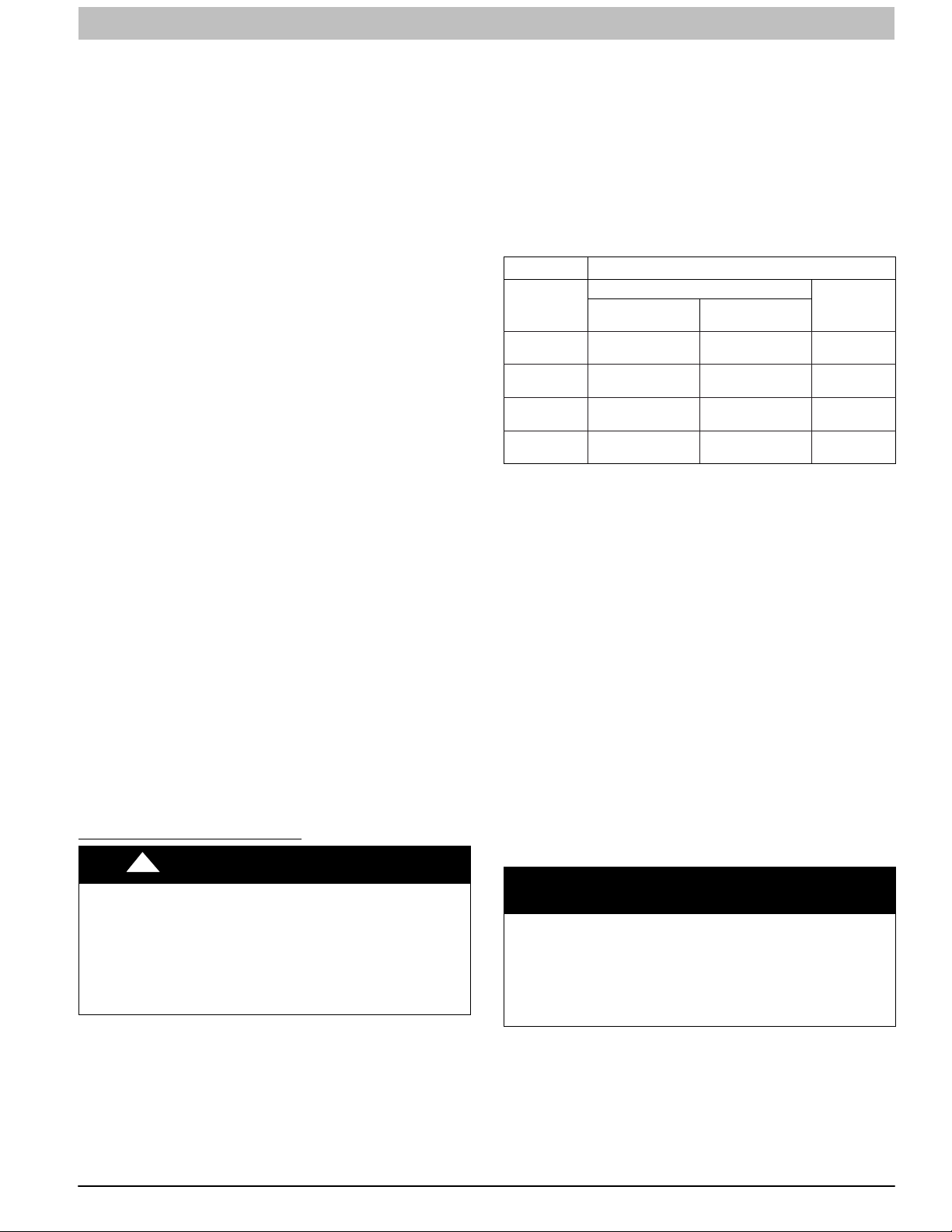
INSTALLATION INSTRUCTIONS Gas Furnace: (F/G)9MXT, (F/G)9MXE
Roll−Out Protection
Provide a minimum 12−in. x 22−in. (305 x 559 mm) piece of
sheet metal for flame roll−out protection in front of burner area
for furnaces closer than 12−in. (305 mm) above the
combustible deck or suspended furnaces closer than 12−in.
(305mm) to joists. The sheet metal MUST extend underneath
the furnace casing by 1−in. (25mm) with the door removed.
The bottom closure panel may be used for flame roll−out
protection when bottom of furnace is used for return air
connection. See Figure 28 for proper orientation of roll−out
shield.
Supply Air Connections
For a furnace not equipped with a cooling coil, the outlet duct
shall be provided with a removable access panel. This opening
shall be accessible when the furnace is installed and shall be of
such a size that the heat exchanger can be viewed for possible
openings using light assistance or a probe can be inserted for
sampling the air stream. The cover attachment shall prevent
leaks.
Connect supply−air duct to flanges on furnace supply−air
outlet. Bend flange upward to 90_ with wide duct pliers. (See
Figure 24) The supply−air duct must be connected to ONLY
the furnace supply−outlet−air duct flanges or air conditioning
coil casing (when used). DO NOT cut main furnace casing side
to attach supply air duct, humidifier, or other accessories. All
supply−side accessories MUST be connected to duct external
to furnace main casing.
Return Air Connections
The return−air duct may be connected to bottom of the furnace.
The side of casing that faces downward may also be used for
return air connection. A combination of the bottom and
downward facing side may also be used. The upward facing
side of the casing cannot be used as a return air connection.
(See Figure 31)
Bottom Return Air Inlet
These furnaces are shipped with bottom closure panel installed
in bottom return−air opening. Remove and discard this panel
when bottom return air is used. To remove bottom closure
panel, see Figure 21 and Figure 20.
Side Return Air Inlet
These furnaces are shipped with bottom closure panel installed
in bottom return−air opening. This panel MUST be in place
when side return air inlet(s) are used without a bottom return air
inlet.
Not all horizontal furnaces are approved for side return air
connections (See Figure 31) Where required by code, seal
bottom closure to furnace with tape, mastic or other durable
sealing method.
Filter Arrangement
!
FIRE, CARBON MONOXIDE AND POISONING
HAZARD
Failure to follow this warning could result in personal
injury, or death.
Never operate a furnace without a filter or filtration device
installed. Never operate a furnace with filter or filtration
device access doors removed.
Furnaces shipped without a filter rack:
There are no provisions for an internal filter in these furnaces.
An external filter rack is required and is purchased separately.
A field supplied accessory air cleaner may also be used in
place of the filter rack.
For upflow applications, the filter can be installed on either side
of the furnace, the bottom of the furnace or any combination of
side and bottom of the furnace. (See Figure 30, Figure 33, and
Figure 32)
WARNING
For downflow applications, the filter rack (or field supplied
accessory air cleaner) must only be connected to the bottom
opening on the furnace (See Figure 29 and Figure 32 and
Table 9).
For horizontal applications, the filter rack (or field supplied
accessory air cleaner) can be connected to the bottom opening
on the furnace. For side return use in the horizontal position,
refer to Figure 31. If both side and bottom openings are used in
Figure 31, each opening used will require a filter.
A filter rack or any field supplied accessory air cleaner can also
be installed in the common return duct prior to entering the
return air opening in any orientation.
See Table 6 for recommended filter size details.
Table 6 Filter Size Information − in. (mm)
FURNACE
CASING
WIDTH
14-3/16
(360)
17-1/2
(445)
21
(533)
24-1/2
(622)
* Recommended to maintain air filter face velocity. See Product Data for part
number.
Refer to the instructions supplied with the Filter Rack or
accessory air filter for additional assembly and installation
options.
SIDE RETURN
16 x 25 x 3/4
(406 x 635 x 19)
16 x 25 x 3/4
(406 x 635 x 19)
16 x 25 x 3/4
(406 x 635 x 19)
16 x 25 x 3/4
(406 x 635 x 19)
FILTER SIZE
14 x 25 x 3/4
(356 x 635 x 19)
16 x 25 x 3/4
(406 x 635 x 19)
20 x 25 x 3/4
(508 x 635 x 19)
24 x 25 x 3/4
(610 x 635 x 19)
BOTTOM
RETURN
FILTER
TYPE
Washable*
Washable*
Washable*
Washable*
Filter and Return Duct Sizing
Pressure drop must be taken into account when sizing filters,
filter racks, IAQ devices, and associated system ductwork. See
Table 7 for a comparison of Pressure Drop (initial/clean
resistance to airflow) versus Airflow for a variety of filter media
types and sizes. These are representative numbers. Consult
the filter or IAQ device manufacturers’ specification sheet for
performance data for a particular filter media or IAQ device.
Design the filter and associated ductwork for the best match of
pressure drop versus filter size. Best practice usually chooses
filter systems with pressure drops under 0.2 in. w.c. (50 Pa),
with the best blower electrical efficiency and system airflow
performance occurring with filter pressure drops under 0.1 in.
w.c. (25 Pa).
Due to the relatively high pressure drops of 1-in (25 mm) thick
after-market filter media, it is recommended that the filtration
system be designed for at least 2-in (51 mm) thick media.
TIPS FROM CONTRACTORS: Install a media cabinet capable
of incorporating a 4-in (102 mm) thick media filter. This allows
room for future upgrades to other IAQ devices.
NOTICE
Design the duct system FIRST to determine how much pressure drop may be allowed in the filter system. See the AIR
DUCTS section. Excessive filter pressure drop often compromises system airflow and duct performance, causes inadequate airflow to the furthest ends of the duct system, as well
as causes excess noise and higher than anticipated electrical
consumption.
Provide duct transitions, as required, to smoothly transition
airflow from the return duct system to the filter (or IAQ device)
to the furnace when the dimensions of the ductwork or furnace
return air opening do not match the required filter or IAQ device
dimensions. See the instructions supplied with
factory-accessory duct adapters.
440 01 4005 05 27
Specifications subject to change without notice.
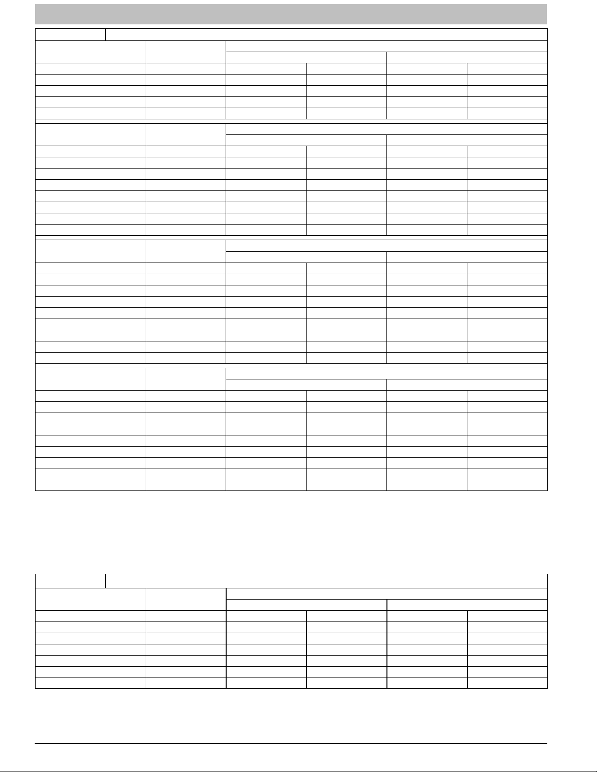
INSTALLATION INSTRUCTIONS Gas Furnace: (F/G)9MXT, (F/G)9MXE
Table 7 Filter Media Pressure Drop (Clean) Versus Airflow - in. w.c. (Pa)
Factory-Accy
14 x 25 Filter
CFM L/s (1-in. / 2.5 cm) (1-in. / 2.5 cm) (2-in. / 5 cm) (1-in. / 2.5 cm) (2-in. / 5 cm)
600 (283) 0.04 (12) 0.07 (17) 0.10 (26) 0.24 (60) 0.16 (40)
800 (378) 0.06 (15) 0.10 (25) 0.15 (39) 0.34 (85) 0.23 (59)
1000 (472) 0.07 (18) 0.13 (34) 0.21 (52) - - 0.32 (81)
1200 (566) 0.08 (20) 0.17 (43) 0.27 (68) - - - -
16x 25 Filter
CFM L/s (1-in. / 2.5 cm) (1-in. / 2.5 cm) (2-in. / 5 cm) (1-in. / 2.5 cm) (2-in. / 5 cm)
600 (283) 0.04 (10) 0.06 (15) 0.09 (22) 0.20 (51) 0.13 (34)
800 (378) 0.05 (13) 0.08 (21) 0.13 (32) 0.29 (72) 0.20 (49)
1000 (472) 0.06 (16) 0.11 (28) 0.17 (43) - - 0.27 (67)
1200 (566) 0.07 (18) 0.14 (36) 0.22 (56) - - - 1400 (661) 0.08 (21) 0.18 (45) 0.28 (70) - - - 1600 (755) 0.09 (23) 0.21 (54) - - - - - 1800 (850) 0.10 (25) 0.26 (64) - - - - - -
20 x 25 Filter
CFM (L/s) (1-in. / 2.5 cm) (1-in. / 2.5 cm) (2-in. / 5 cm) (1-in. / 2.5 cm) (2-in. / 5 cm)
800 (378) 0.04 (11) 0.06 (16) 0.09 (24) 0.22 (55) 0.15 (37)
1000 (472) 0.05 (13) 0.08 (21) 0.13 (32) 0.29 (72) 0.20 (49)
1200 (566) 0.06 (15) 0.11 (27) 0.16 (41) - - 0.25 (63)
1400 (661) 0.07 (17) 0.13 (33) 0.20 (51) - - 0.31 (79)
1600 (755) 0.08 (19) 0.16 (40) 0.24 (61) - - - 1800 (850) 0.08 (21) 0.18 (47) 0.29 (73) - - - 2000 (944) 0.09 (23) 0.21 (54) - - - - - 2200 (1038) 0.09 (24) 0.25 (62) - - - - - -
25 x 25 Filter
CFM L/s (1-in. / 2.5 cm) (1-in. / 2.5 cm) (2-in. / 5 cm) (1-in. / 2.5 cm) (2-in. / 5 cm)
800 (378) 0.03 (9) 0.05 (12) 0.07 (18) 0.17 (43) 0.11 (28)
1000 (472) 0.04 (11) 0.06 (16) 0.09 (24) 0.22 (55) 0.15 (37)
1200 (566) 0.05 (13) 0.08 (20) 0.12 (31) 0.27 (68) 0.18 (47)
1400 (661) 0.06 (15) 0.10 (24) 0.15 (38) - - 0.23 (58)
1600 (755) 0.06 (16) 0.11 (29) 0.18 (45) - - 0.28 (69)
1800 (850) 0.07 (18) 0.13 (34) 0.21 (53) - - - 2000 (944) 0.08 (19) 0.16 (39) 0.24 (61) - - - 2200 (1038) 0.08 (21) 0.18 (45) 0.28 (70) - - - -
* Representative estimates from filter manufacturer data sheets.
Washable
Factory-Accy
Washable
Factory-Accy
Washable
Factory-Accy
Washable
See manufacturers’ specifications for pressure drop versus airflow data for specific filter media.
If the filter size that you are looking for is not contained in Table 7, refer to Table 8 for a comparison of Pressure Drop (initial/clean
resistance to airflow) versus Face Velocity for a variety of filter media types.
The following equations relate Face Velocity (FPM), Filter Area and Airflow (CFM):
Filter Face Velocity = Airflow / Filter Area
Minimum Filter Area = Rated System Airflow / Maximum Filter Face Velocity
Representative After-Market Filter Media*
Fiberglass* Pleated*
Representative After-Market Filter Media*
Fiberglass* Pleated*
Representative After-Market Filter Media*
Fiberglass* Pleated*
Representative After-Market Filter Media*
Fiberglass* Pleated*
Table 8 Filter Media Pressure Drop (Clean) Versus Velocity - in. w.c. (Pa)
Factory-Accy
Face Velocity
FPM (m/s) (1-in. / 2.5 cm) (1-in. / 2.5 cm) (2-in. / 5 cm) (1-in. / 2.5 cm) (2-in. / 5 cm)
200 (1) 0.04 (10) 0.05 (13) 0.08 (20) 0.18 (47) 0.12 (31)
300 (1.5) 0.05 (14) 0.09 (22) 0.13 (34) 0.30 (75) 0.21 (52)
400 (2) 0.07 (17) 0.13 (32) 0.20 (50) - - 0.31 (78)
500 (2.5) 0.08 (21) 0.18 (44) 0.27 (69) - - - -
600 (3) 0.09 (23) 0.23 - - - - - - -
700 (3.6) 0.10 (26) 0.29 - - - - - - -
* Representative estimates from filter manufacturer data sheets.
Washable
Fiberglass* Pleated*
See manufacturers’ specifications for pressure drop versus airflow data for specific filter media.
Representative After-Market Filter Media*
28 440 01 4005 05
Specifications subject to change without notice.

INSTALLATION INSTRUCTIONS Gas Furnace: (F/G)9MXT, (F/G)9MXE
Figure 29
Figure 30
Downflow Return Air
Configurations and Restrictions
L10F033
Upflow Return Air Configurations
and Restrictions
External Filter Cabinet Configurations
Figure 32 Accessory Bottom Filter Rack
L10F031
B
A
Figure 31
HORIZONTAL TOP
RETURN NOT
PERMITTED FOR
ANY MODEL
SIDE RETURN AIR NOT PERMITTED FOR 2000 CFM AND
Horizontal Return Air
Configurations and Restrictions
ABOVE OF AIR FLOW
L10F032
L10F034
A
22−5/16
(566.4)
28−7/16
(722.2)
2−3/16
(55.5)
Table 9 Dimensional Drawing − in. (mm)
KIT NO.
NAHB00501FF
NAHB00601FF
NAHB00701FF
NAHB00801FF
FURNACE
WIDTH
14−3/16
(360.4)
17−1/2
(444.5)
21
(533.4)
24−1/2
(622.3)
A B
11−3/8
(289)
14−5/8
(371.5)
18−1/8
(460.4)
21−5/8
(549.3)
14−1/4
(362)
17−5/8
(447.7)
21−1/8
(536.6)
24−5/8
(625.5)
440 01 4005 05 29
Specifications subject to change without notice.

INSTALLATION INSTRUCTIONS Gas Furnace: (F/G)9MXT, (F/G)9MXE
Figure 33 Accessory Side Filter Rack
FURNACE
FILTER
FRAME
FILTER
TABS
DOOR
⅜”
(1 cm)
TABS
½”
(1.3 cm)
14 ½”
(37 cm)
OPENING
17 ⅛”
(43.5 cm)
1 ¼”
(3 cm)
(TYP.)
1
/
1
(3 cm)
25 ⅛”
4”
(64 cm)
23 ⅛”
(59 cm)
OPENING
¾”
(2 cm)
16 ⅛”
(41 cm)
L10F027
2 ⅜”
(6 cm)
your local distributor. The duct system should be sized to
handle the required system design CFM at the design external
static pressure. The furnace airflow rates are provided in the
Service and Technical Support Manual. When a furnace is
installed so that the supply ducts carry air circulated by the
furnace to areas outside the space containing the furnace, the
return air shall also be handled by duct(s) sealed to the furnace
casing and terminating outside the space containing the
furnace.
Secure ductwork with proper fasteners for type of ductwork
used. Seal supply− and return−duct connections to furnace
with code approved tape or duct sealer.
NOTE: Flexible connections should be used between ductwork
and furnace to prevent transmission of vibration.
Ductwork passing through unconditioned space should be
insulated to enhance system performance. When air
conditioning is used, a vapor barrier is recommended.
Maintain a 1−in. (25 mm) clearance from combustible materials
to supply air ductwork for a distance of 36−in. (914 mm)
horizontally from the furnace. See current edition of the NFPA
90B or local code for further requirements.
Return Duct Sizing
Refer to the Filter Selection and Duct Sizing section for
information on the proper selection of filter sizes and the
associated ductwork and duct transitions. Improperly designed
filtering systems and return ductwork are the most common
causes of airflow and/or noise complaints in HVAC systems.
Ductwork Acoustical Treatment
NOTE: Metal duct systems that do not have a 90 degree elbow
and 10 ft. (3 M) of main duct to the first branch take−off may
require internal acoustical lining. As an alternative, fibrous
ductwork may be used if constructed and installed in
accordance with the latest edition of SMACNA construction
standard on fibrous glass ducts. Both acoustical lining and
fibrous ductwork shall comply with current edition of the NFPA
90B as tested by UL Standard 181 for Class 1 Rigid air ducts.
NOTE: For horizontal applications, the top most flange may be
bent past 90_ to allow the evaporator coil to hang on the flange
temporarily while the remaining attachment and sealing of the
coil are performed.
L12F023
Air Ducts
GAS PIPING
!
WARNING
FIRE OR EXPLOSION HAZARD
NOTICE
Failure to follow this warning could result in personal
injury, death, and/or property damage.
Many states, provinces and localities are considering or have
implemented standards and/or restrictions on duct sizing
practices, ductwork leakage, and/or ductwork thermal, airflow
and electrical efficiencies. CONSULT LOCAL CODE OFFICIALS for ductwork design and performance requirements in
your area.
Never purge a gas line into a combustion chamber.
Never test for gas leaks with an open flame. Use a
commercially available soap solution made specifically
for the detection of leaks to check all connections. A
fire or explosion may result causing property damage,
personal injury or loss of life.
General Requirements
The duct system should be designed and sized according to
accepted national standards such as those published by: Air
Conditioning Contractors Association (ACCA Manual D), Sheet
Metal and Air Conditioning Contractors National Association
(SMACNA) or American Society of Heating, Refrigerating and
Air Conditioning Engineers (ASHRAE) or consult The Air
Systems Design Guidelines reference tables available from
30 440 01 4005 05
Specifications subject to change without notice.
FIRE OR EXPLOSION HAZARD
Failure to follow this warning could result in personal
injury, death, and/or property damage.
Use proper length of pipe to avoid stress on gas control manifold and a gas leak.
!
WARNING

INSTALLATION INSTRUCTIONS Gas Furnace: (F/G)9MXT, (F/G)9MXE
!
WARNING
FIRE OR EXPLOSION HAZARD
Failure to follow this warning could result in personal
injury, death, and/or property damage.
Gas valve inlet and/or inlet pipe must remain capped
until gas supply line is permanently installed to protect
the valve from moisture and debris. Also, install a sediment trap in the gas supply piping at the inlet to the
gas valve.
Gas piping must be installed in accordance with national and
local codes. Refer to current edition of the NFGC in the U.S.A.
Refer to current edition of the CAN/CSA B149.1 in Canada.
Installations must be made in accordance with all authorities
having jurisdiction. If possible, the gas supply line should be a
separate line running directly from meter to furnace.
NOTE: Use a back−up wrench on the inlet of the gas valve
when connecting the gas line to the gas valve.
NOTICE
In the state of Massachusetts:
1. Gas supply connections MUST be performed by a licensed plumber or gas fitter.
2. When flexible connectors are used, the maximum
length shall not exceed 36−in. (915 mm).
3. When lever handle type manual equipment shutoff
valves are used, they shall be T−handle valves.
4. The use of copper tubing for gas piping is NOT approved by the state of Massachusetts.
Table 10 Maximum Capacity of Pipe
NOMINAL
IRON PIPE
SIZE
IN. (MM)
1/2 (13)
3/4 (19)
1 ( 25)
1‐1/4 (32)
1‐1/2 (39)
* Cubic ft of gas per hr for gas pressures of 0.5 psig (14-In. W.C.) or less and
a pressure drop of 0.5-In. W.C. (based on a 0.60 specific gravity gas). Ref: Table 10
above, and 6.2 of current edition of the NFPA54/ANSI Z223.1.
An accessible manual equipment shutoff valve MUST be
installed external to furnace casing and within 6 ft. (1.8 M) of
furnace.
Install a sediment trap externally in riser leading to furnace as
shown in Figure 34. Connect a capped nipple into lower end of
tee. Capped nipple should extend below level of furnace gas
controls. Place a ground joint union between furnace gas
control valve and exterior manual equipment gas shutoff valve.
INTERNAL
DIA.
IN. (MM)
0.622 (158) 175 120 97 82 73
0.824 (20.9) 360 250 200 170 151
1.049 (26.6) 680 465 375 320 285
1.380 (35.0) 1400 950 770 660 580
1.610 (40.9) 2100 1460 1180 990 900
LENGTH OF PIPE − FT (M)
10
(3.0)20(6.0)30(9.1)40(12.1)50(15.2)
Figure 34 Typical Gas Pipe Arrangement
Refer to Table 10 for recommended gas pipe sizing. Risers
must be used to connect to furnace and to meter. Support all
gas piping with appropriate straps, hangers, etc. Use a
minimum of one hanger every 6 ft. (1.8 M). Joint compound
(pipe dope) should be applied sparingly and only to male
threads of joints. Pipe dope must be resistant to the action of
propane gas.
!
WARNING
FIRE OR EXPLOSION HAZARD
A failure to follow this warning could result in personal injury, death, and/or property damage.
If local codes allow the use of a flexible gas appliance
connector, always use a new listed connector. Do not use
a connector which has previously served another gas appliance. Black iron pipe shall be installed at the furnace
gas control valve and extend a minimum of 2−in. (51 mm)
outside the furnace.
!
CAUTION
FURNACE DAMAGE HAZARD
Failure to follow this caution may result in furnace damage.
Connect gas pipe to furnace using a backup wrench to
avoid damaging gas controls and burner misalignment.
L10F030
A 1/8−in. (3 mm) NPT plugged tapping, accessible for test
gauge connection, MUST be installed immediately upstream of
gas supply connection to furnace and downstream of manual
equipment shutoff valve.
Piping should be pressure and leak tested in accordance with
the current addition of the NFGC in the United States, local,
and national plumbing and gas codes before the furnace has
been connected. Refer to current edition of the NSCNGPIC in
Canada. After all connections have been made, purge lines
and check for leakage at furnace prior to operating furnace.
NOTE: The furnace gas control valve inlet pressure tap
connection is suitable to use as test gauge connection
providing test pressure DOES NOT exceed maximum 0.5 psig
(14−in. w.c.) stated on gas control valve. (See Figure 35)
440 01 4005 05 31
Specifications subject to change without notice.

INSTALLATION INSTRUCTIONS Gas Furnace: (F/G)9MXT, (F/G)9MXE
Figure 35 Gas Valves
Automatic Gas Valve (Two−Stage)
ON/OFF Switch
1/2” NPT Inlet
1/8” NPT Inlet
Pressure Tap
Representative drawing only, some models may vary.
Gas Valve (Single Stage)
ON/OFF Switch
1/2” NPT Inlet
Regulator Seal Cap
Regulator Adjustment
Regulator Seal Cap under Cap
1/8” NPT Manifold
Pressure Tap
Regulator Seal Cap
Regulator Adjustment
Regulator Seal Cap under Cap
1/2” NPT Outlet
A11152
If pressure exceeds 0.5 psig (14−in. w.c.), gas supply pipe must
be disconnected from furnace and capped before and during
supply pipe pressure test. If test pressure is equal to or less
than 0.5 psig (14−in. w.c.), turn off electric shutoff switch
located on furnace gas control valve and accessible manual
equipment shutoff valve before and during supply pipe
pressure test. After all connections have been made, purge
lines and check for leakage at furnace prior to operating
furnace.
The gas supply pressure shall be within the maximum and
minimum inlet supply pressures marked on the rating plate with
the furnace burners ON and OFF.
Gas entry can be from left or right side, or top panel. (See
Figure 36 and Figure 37)
Gas Pipe Grommet
For direct vent (2-pipe) applications, the knockout for the gas
pipe must be sealed to prevent air leakage. Remove the
knockout, install the grommet in the knockout, then insert the
gas pipe. The grommet is included in the loose parts bag. (See
Figure 36)
Figure 36 Gas Entry
Left Side Gas Entry. Gas Pipe
Grommet Required For Direct
Vent Applications.
Gas Pipe Grommet Required
For Direct Vent Applications
1/8” NPT Inlet
Pressure Tap
1/8” NPT Manifold
Pressure Tap
Representative drawing only, some models may vary.
1/2” NPT Outlet
A11153
A11338
Figure 37 Alternate Gas and Electric Entry
1ï1/2 inch for Gas
7/8 inch for 115 VAC Electric
NOTE: Top plate may be field drilled for
alternate gas and 115 VAC electric entry
L170125
32 440 01 4005 05
Specifications subject to change without notice.

INSTALLATION INSTRUCTIONS Gas Furnace: (F/G)9MXT, (F/G)9MXE
ELECTRICAL CONNECTIONS
!
WARNING
ELECTRICAL SHOCK, FIRE OR EXPLOSION HAZARD
Failure to follow safety warnings could result in dangerous
operation, serious injury, death or property damage.
Improper servicing could result in dangerous operation,
serious injury, death or property damage.
S Before servicing, disconnect all electrical power to
furnace.
S When servicing controls, label all wires prior to dis-
connecting. Reconnect wires correctly.
S Verify proper operation after servicing.
S Always reinstall access doors after completing
service and maintenance.
!
ELECTRICAL SHOCK HAZARD
Failure to follow this warning could result in personal injury or
death.
Blower door switch opens 115−v power to control. No component
operation can occur. Do not bypass or close switch with blower
door removed.
See Figure 38 for field wiring diagram showing typical field
115 −v wiring. Check all factory and field electrical connections
for tightness.
Field−supplied wiring shall conform with the limitations of 63°F
(33°C) rise.
WARNING
115−V Wiring
Furnace must have a 115-v power supply properly connected
and grounded.
NOTE: Proper polarity must be maintained for 115-v wiring. If
polarity is incorrect, control status indicator light flashes rapidly
and furnace does NOT operate.
Verify that the voltage, frequency, and phase correspond to that
specified on unit rating plate. Also, check to be sure that
service provided by utility is sufficient to handle load imposed
by this equipment. Refer to rating plate or Table 11 for
equipment electrical specifications.
U.S.A. Installations: Make all electrical connections in
accordance with the current edition of the National Electrical
Code (NEC) NFPA 70 and any local codes or ordinances that
might apply.
Canadian Installations: Make all electrical connections in
accordance with the current edition of the Canadian Electrical
Code CSA C22.1 and any local codes or ordinances that might
apply.
!
FIRE HAZARD
Failure to follow this warning could result in personal injury,
death, or property damage.
Do not connect aluminum wire between disconnect switch
and furnace. Use only copper wire.
WARNING
!
ELECTRICAL SHOCK AND FIRE HAZARD
Failure to follow this warning could result in personal injury,
death, or property damage.
The cabinet MUST have an uninterrupted or unbroken ground
according to current edition of the NEC NFPA 70 or local codes
to minimize personal injury if an electrical fault should occur. In
Canada, refer to current edition of the Canadian Electrical Code
CSA C22.1. This may consist of electrical wire, conduit
approved for electrical ground or a listed, grounded power cord
(where permitted by local code) when installed in accordance
with existing electrical codes. Refer to the power cord
manufacturer’s ratings for proper wire gauge.
Do not use gas piping as an electrical ground.
!
FURNACE MAY NOT OPERATE HAZARD
Failure to follow this caution may result in intermittent furnace
operation.
Furnace control must be grounded for proper operation or
else control will lock out. Control must remain grounded
through green/yellow wire routed to gas valve and manifold
bracket screw.
WARNING
CAUTION
SWITCH
Use a separate, fused branch electrical circuit with a properly
sized fuse or circuit breaker for this furnace. See Table 11 for
wire size and fuse specifications. A readily accessible means of
electrical disconnect must be located within sight of the
furnace.
COPPER
WIRE ONLY
ALUMINUM
WIRE
A11146
440 01 4005 05 33
Specifications subject to change without notice.

INSTALLATION INSTRUCTIONS Gas Furnace: (F/G)9MXT, (F/G)9MXE
Figure 38 Heating and Cooling Application Single−Stage Wiring Diagram
FIELD 24-V WIRING
FIELD 115-, 208/230-, 460-V WIRING
FACTORY 24-V WIRING
FACTORY 115-V WIRING
FIVE WIRE
THREE-WIRE
HEATING-ONLY
BLOWER DOOR SWITCH
BLK
WHT
115-V FIELD-
SUPPLIED
BLK
WHT
GND
AUXILIARY
J-BOX
DISCONNECT
GND
NOTE 2
W
C
R
O
N
T
G
R
O
COM
L
Y
24-V
TERMINAL
WCR GY
NOTE 1
THERMOSTAT
TERMINALS
CONDENSING
UNIT
TWO
WIRE
FIELD-SUPPLIED
DISCONNECT
GND
208/230- OR
460-V
THREE
PHASE
208/230-V
SINGLE
PHASE
BLOCK
FURNACE
NOTES: Connect Y-terminal in furnace as shown for proper blower operation.
1.
2.
Some thermostats require a "C" terminal connection as shown.
3.
If any of the original wire, as supplied, must be replaced, use
same type or equivalent wire.
Heating and Cooling Application Two−Stage Wiring Diagram with Single−Stage Thermostat
A11387
BLOWER
DOOR
SWITCH
BLK
WHT
115 ïVOLT FIELDï
SUPPLIED
FUSED
DISCONNECT
BLK
WHT
GND
J−Box Installation
!
WARNING
THREEïWIRE
HEATINGï
ONLY
JUNCTION
BOX
FURNACE
FIVE
WIRE
W2
C
COM
O
N
W/W1
T
Y/Y2
R
O
R
L
G
24ïVOLT
TERMINAL
BLOCK
NOTE 2
W
C
NOTE 1
NOTES: 1.
FIELD 24ïVOLT WIRING
FIELD 115ï, 208/230ï, 460ïVOLT WIRING
FACTORY 24ïVOLT WIRING
FACTORY 115ïVOLT WIRING
1ïSTAGE
YR
G
THERMOSTAT
TERMINALS
CONDENSING
UNIT
Connect Y/Y2ïterminal as shown for proper operation.
Some thermostats require a ”C” terminal connection as shown.
2.
If any of the original wire, as supplied, must be replaced, use
3.
same type or equivalent wire.
FIELDïSUPPLIED
FUSED DISCONNECT
GND
208/230ï OR
460ïVOLT
THREE
PHASE
208/230ï
VOLT
SINGLE
PHASE
A11401
FIRE OR ELECTRICAL SHOCK HAZARD
Failure to follow this warning could result in personal
injury, death, or property damage.
High voltage field connections must be located in J−Box
with furnace, or in field supplied external disconnect
mounted to furnace.
If field−supplied manual disconnect switch is to be
mounted on furnace casing side, select a location where
a drill or fastener cannot damage electrical or gas
components.
34 440 01 4005 05
Specifications subject to change without notice.

INSTALLATION INSTRUCTIONS Gas Furnace: (F/G)9MXT, (F/G)9MXE
Figure 39 Optional J−Box Locations
OPTIONAL
J−BOX
LOCATIONS
Representative drawing only, some models may vary in appearance.
L12F024
Figure 40 J−Box Bracket Installation
J−BOX
MOUNTING
SCREWS,
BLUNT−TIP
J−BOX
MOUNTING
BRACKET
GROUND
SCREW
J−BOX COVER
A170137
The J−Box must be used when field line voltage electrical
connections are made to the furnace wiring harness inside the
furnace casing. The J−Box cover is not required if an external
electrical box is attached to the outside of the furnace casing.
The field wiring and main wiring harness are grounded with the
furnace box is grounded to the green ground screw of the
J−Box bracket and the earth ground of the field electrical
supply. The field ground wire and furnace main ground wire are
grounded when the J−Box bracket is attached to the furnace
and the field ground wire and factory ground wire are secured
to the bracket grounding screw. If the J−Box cover is not used,
the field and factory spliced connections must be located inside
the external electrical box. Do not leave splice connections
unprotected inside the furnace.
The J−Box cover, mounting bracket and screws are shipped in
the loose parts bag included with the furnace. See Figure 39
for J−Box mounting locations.
The J−Box mounting bracket and green ground screw are used
as a grounding point for all line voltage wiring options. The
J−Box cover may be omitted when electrical connections are
made inside an external electrical box mounted external to the
casing.
External Electrical Box on Furnace Casing
Note: Check to ensure that external electrical box does not
interfere with ductwork, gas piping or the indoor coil drain. See
Figure 37 for alternate electric entry through top panel.
1. Select and remove 7/8−in. (22 mm) knock−out on the
desired side of the casing. Remove the knock−out from
the casing.
NOTE: If electrical entry through the furnace top panel is used,
a 7/8−in. (22 mm) hole must be drilled through the top panel.
2. Drill two (2) 1/8−in. (3 mm) pilot holes through the
dimples in the furnace casing near the 7/8−in. knock−out.
NOTE: If electrical entry through the furnace top panel is used,
mark the screw hole locations using the mounting holes in the
external electrical box as a template.
For a side−mounted external electrical box, complete the
following:
3. Align the J−Box bracket with the knock−out inside the
furnace casing.
4. Install the threaded end of a strain−relief bushing through
the J−Box bracket and the furnace casing. Strain−relief
bushing should be installed so that the bushing can be
tightened around the wiring harness inside the furnace
casing.
5. Align the field−supplied external electrical box with the
7/8−in. (22 mm) knock−out.
6. Install and tighten the lock−nut on the strain−
relief
bushing inside the external electrical box.
7. Fasten the external electrical box to the furnace casing
using two (2) sheet metal screws.
8. Route field power wiring into external electrical box.
9. Pull furnace line voltage power wires through strain−relief
bushing of the external electrical box.
10. Pull the ground wire of the field line voltage wiring
through the strain−relief bushing into the furnace casing.
11. Install the green ground screw to the J−Box bracket and
attach both ground wires to the green ground screw.
12. Connect any code required external disconnect(s) to field
power wiring.
13. Connect field power and neutral leads to furnace power
leads inside the external electrical box as shown in
Figure 40.
For a top panel−mounted external electrical box, complete
the following:
1. Drill two (2) 1/8−in. (3 mm) pilot holes through the
dimples in the furnace casing near the 7/8−in. knock−out
on the side of the casing. Do not remove the knock−out
in the side of the casing.
2. Align the J−Box bracket with the pilot holes inside the
furnace casing.
3. Install two (2) screws through the outside of the casing to
secure the J−Box bracket to the furnace casing.
4. Route field power wiring into external electrical box.
5. Pull furnace line voltage power wires through strain−relief
bushing of the external electrical box.
6. Pull the ground wire of the field line voltage wiring
through the strain−relief bushing into the furnace casing.
7. Install the green ground screw to the J−Box bracket and
attach both ground wires to the green ground screw.
440 01 4005 05 35
Specifications subject to change without notice.

INSTALLATION INSTRUCTIONS Gas Furnace: (F/G)9MXT, (F/G)9MXE
8. Connect any code required external disconnect(s) to field
power wiring.
9. Connect field power and neutral leads to furnace power
leads inside the external electrical box as shown in
Figure 41.
Figure 41
Field−Supplied External Electrical
Box on Furnace Casing
FIRE, EXPLOSION, ELECTRICAL SHOCK, AND CARBON
MONOXIDE POISONING HAZARD
Failure to follow this warning could result in dangerous
operation, personal injury, death, or property damage.
Do no drill into blower shelf of furnace to route control wiring.
Route any control or accessory wiring to the blower
compartment through external knockouts on the casing.
! WARNING
24−V Wiring
Make field 24−V connections at the 24−V terminal strip. (See
GROUND
NEUTRAL
LINE
VOLTAGE
Figure 43 or Figure 44) Connect terminal Y/Y2 as shown in
Figure 38 for proper cooling operation. Use only AWG No. 18,
color−coded, copper thermostat wire.
NOTE: Use AWG No. 18 color-coded copper thermostat wire
for lengths up to 100 ft. (30.5 M). For wire lengths over 100 ft.,
use AWG No. 16 wire.
The 24−v circuit contains an automotive−type, 3−amp. fuse
located on the control. Any direct shorts during installation,
service, or maintenance could cause this fuse to blow. If fuse
replacement is required, use ONLY a 3−amp. fuse of identical
size. (See Figure 43 or Figure 44)
See the Service and Technical Support manual for detailed
instructions on control wiring and setup.
Thermostats and Control Settings for
(F/G)9MXT Two−Stage Furnaces
A10141
Power Cord Installation in Furnace J−Box
NOTE: Power cords must be able to handle the electrical
requirements listed in Table 11. Refer to power cord
manufacturer’s listings.
1. Install J−Box mounting bracket to inside of furnace
casing. (See Figure 40)
2. Route listed power cord through 7/8−in. (22 mm)
diameter hole in casing and J−Box bracket.
3. Secure power cord to J−Box bracket with a strain relief
bushing or a connector approved for the type of cord
used.
4. Pull furnace power wires through 1/2−in. (12 mm)
diameter hole in J−Box. If necessary, loosen power wires
from strain—relief wire−tie on furnace wiring harness.
5. Connect field ground wire and factory ground wire to
green ground screw on J−Box mounting bracket as
shown in Figure 40.
6. Connect power cord power and neutral leads to furnace
power leads as shown in Figure 38.
7. Attach furnace J−Box cover to mounting bracket with
screws supplied in loose parts bag. Do not pinch wires
between cover and bracket.
BX Cable Installation in Furnace J−Box
1. Install J−Box mounting bracket to inside of furnace
casing.
2. Route BX connector through 7/8−in. (22 mm) diameter
hole in casing and J−Box bracket.
3. Secure BX cable to J−Box bracket with connectors
approved for the type of cable used.
4. Connect field ground wire and factory ground wire to
green ground screw on J−Box mounting bracket as
shown in Figure 40.
5. Connect field power and neutral leads to furnace power
leads. as shown in Figure 38.
6. Attach furnace J−Box cover to mounting bracket with
screws supplied in loose parts bag. Do not pinch wires
between cover and bracket.
36 440 01 4005 05
Specifications subject to change without notice.
A single−stage or two−stage heating and single−stage or
two−stage cooling thermostat may be used with the furnace.
Refer to typical thermostat wiring diagrams and the Sequence
of Operation section of the Service and Technical Support
manual for details on configuring the furnace control board.
Consult the thermostat installation instructions for specific
information about configuring the thermostat.
Thermostats and Control Settings for
(F/G)9MXE Single−Stage Furnaces
A single stage heating and single−stage or two−stage cooling
thermostat may be used with the furnace. Refer to typical
thermostat wiring diagrams and the Sequence of Operation
section of the Service and Technical Support manual for details
on configuring the furnace control board. Consult the
thermostat installation instructions for specific information about
configuring the thermostat.
Accessories (See Figure 42, Figure 43, and/or
Figure 44)
1. Electronic Air Cleaner (EAC)
Connect an accessory Electronic Air Cleaner (if used)
using 1/4−in female quick connect terminals to the two
male 1/4−in quick−connect terminals on the control
board marked EAC−1 and EAC−2. The terminals are
rated for 115VAC, 1.0 amps maximum and are
energized during blower motor operation.
2. Humidifier (HUM)
(F/G)9MXT There are two humidifier outputs on the
furnace control. The 115 VAC HUM terminal is
energized when the Induced Draft Relay closes. The
24 VAC HUM terminal is energized when the low
pressure switch closes during a call for heat. Connect
an accessory 115 VAC accessory humidifier to the
HUM terminal and L2 on the furnace control. Connect
a 24 VAC humidifier to the 24 VAC HUM terminal and
C screw terminal strip on the control board thermostat
strip. (See Figure 43)
(F/G)9MXE The HUM 24 VAC terminal is a 24 VAC
output energized when the gas valve relay closes
during a call for heat.
NOTE: There is not a HUM 115V terminal on the single stage
ECM furnace control board. Available ONLY on the two−stage
ECM and PSC single−stage furnace control board.

INSTALLATION INSTRUCTIONS Gas Furnace: (F/G)9MXT, (F/G)9MXE
Connect an accessory 24 VAC, 0.5 amp. Maximum (if
used) to the 1/4−in. male quick−connect HUM 24 VAC
terminal and C screw terminal on the control board
thermostat strip. (See Figure 44)
Power from an alternate power supply that non-sinusoidal may
damage the furnace or cause erratic furnace operation.
Contact the alternate power supply manufacturer for
specifications and details.
NOTE: If the humidifier has its own 24 VAC power supply, an
isolation relay may be required. Connect the 24 VAC coil of the
isolation relay to the HUM 24 VAC and C screw terminal on the
control board thermostat strip. (See Figure 42)
Alternate Power Supplies
This furnace is designed to operate on a utility generated
power which has a smooth sinusoidal waveform. If the furnace
is to be operated on a generator or other alternate power
supply, the alternate power supply must produce a smooth
sinusoidal waveform for compatibility with furnace electronics.
The alternate power supply must generate the same voltage,
phase, and frequency (Hz) as shown in Table 11 or on the
furnace rating plate.
Figure 42 Isolation Relay for Humidifiers with Internal Power Supply
To Humidifier Leads
24 V
Coil
To HUM 24 VAC Terminal
On Furnace Control Board
To Humidifier Leads
To Com/24V Screw Terminal
on Thermostat Strip
A11157
440 01 4005 05 37
Specifications subject to change without notice.

INSTALLATION INSTRUCTIONS Gas Furnace: (F/G)9MXT, (F/G)9MXE
Table 11 Electrical Data
(F/G)9MXT TWO−STAGE, ECM BLOWER FURNACES
UNIT SIZE
VOLTS−
HERTZ−
PHASE
OPERATING
VOLTAGE
RANGE*
Max* Min*
MAXIMUM
UNIT
AMPS
UNIT
AMPACITY#
MINIMUM
WIRE
SIZE
AWG
MAXIMUM
WIRE
LENGTH
FT (M)}
MAXIMUM
FUSE OR CKT
BKR
AMPS{
0401410 115-60-1 127 104 7.5 10.3 14 36 (11.0) 15
0401712 115-60-1 127 104 7.5 10.3 14 36 (11.0) 15
0601412 115-60-1 127 104 7.6 10.4 14 35 (10.7) 15
0601714 115-60-1 127 104 10.7 14.3 14 26 (7.9) 15
0801716 115-60-1 127 104 10.1 13.5 14 27 (8.2) 15
0802120 115-60-1 127 104 13.1 17.3 12 33 (10.1) 20
1002120 115-60-1 127 104 13.5 17.7 12 32 (9.8) 20
1202422 115-60-1 127 104 12.0 15.9 12 36 (11.0) 20
(F/G)9MXE SINGLE−STAGE, ECM BLOWER FURNACES
UNIT SIZE
VOLTS−
HERTZ−
PHASE
OPERATING
VOLTAGE
RANGE*
Max* Min*
MAXIMUM
UNIT
AMPS
UNIT
AMPACITY#
MINIMUM
WIRE
SIZE
AWG
MAXIMUM
WIRE
LENGTH
FT (M)}
MAXIMUM
FUSE OR CKT
BKR
AMPS{
0261410 115-60-1 127 104 5.1 7.3 14 51 (15.5) 15
0401410 115-60-1 127 104 7.5 10.3 14 36 (11.0) 15
0401712 115-60-1 127 104 7.5 10.3 14 36 (11.0) 15
0601412 115-60-1 127 104 7.6 10.4 14 35 (10.7) 15
0601714 115-60-1 127 104 10.7 14.3 14 26 (7.9) 15
0801716 115-60-1 127 104 10.1 13.5 14 27 (8.2) 15
0802120 115-60-1 127 104 13.1 17.3 12 33 (10.1) 20
1002120 115-60-1 127 104 13.5 17.7 12 32 (9.8) 20
1202422 115-60-1 127 104 12.0 15.9 12 36 (11.0) 20
* Permissible limits of the voltage range at which the unit operates satisfactorily.
# Unit ampacity = 125 percent of largest operating component’s full load amps plus 100 percent of all other potential operating components’ (EAC, humidifier, etc.) full load
amps.
{ Time−delay type is recommended.
} Length shown is as measured one way along wire path between unit and service panel for maximum 2 percent voltage drop.
Figure 43 Example of Two−Stage Furnace Control for ECM Blower Motor − (F/G)9MXT
SET UP SWITCHES
THERMOSTAT TYPE (TT)
AND HEAT OFF−DELAY
W2 Y1 DHUM G COM W/W1 Y/Y2 R
24−V THERMOS TAT
TERMINALS
SW1
ON
OFF
3−AMP FUSE
LED OPERATION
& DIAGNOSTIC LIGHT
COM
24V
BLOWER SPEED
TERMINALS
115−VAC (L2)
NEUTRAL
CONNECTIONS
38 440 01 4005 05
Specifications subject to change without notice.
24V
COM
HI HT
COOL
LO H T
SPARE 2
SPARE 1
TEST / TWIN
24VAC
FUSE 3−AMP
COM/BLUE 24VAC/RED
24V MTR TAPS
EAC−2
L2
TWINNING AND/OR
SW1
ON
OFF
COMPONENT TEST
1 2 3
TT
TERMINAL
OFF
DLY
PLT
HUM
PL1
1
EAC TERMINAL
115 VAC 1.0 AMP
MAX
EAC−1
L1 BL−1 XFMR
115 VAC LINE (L1)
INPUT
HUMIDIFIER TERMINAL
(24 VAC 0.5 AMPS MAX)
TRANSFORMER
24 VAC CONNECTIONS
P−1 LOW VOLTAGE
11 5 VA C
BLOWER POWER (BL1)
CONNECTION
HUM
115 VAC HUM
11 5 VA C
TRANSFORMER
PRIMARY
P2 − HOT SURFACE
IGNITER/INDUCE R
MOTOR CONNECTION
HSIR
1
HSI HI LO
IHI/LOR
IDM
IDR
PL2
L12F037

INSTALLATION INSTRUCTIONS Gas Furnace: (F/G)9MXT, (F/G)9MXE
Figure 44 Example of Single Stage Furnace Control for ECM Blower Motor − (F/G)9MXE
HEAT OFFïDELAY
120 180
90 150
TWINNING AND/OR
COMPONENT TEST
TERMINAL
HUMIDIFIER TERMINAL
(24ïVAC 0.5 AMP MAX)
TRANSFORMER 24VAC
CONNECTIONS
P1 ï LOW VOLTAGE MAIN
HARNESS CONNECTOR
24ïV THERMOSTAT
3ïAMP FUSE
LED OPERATION &
DIAGNOSTIC LIGHT
BLOWER SPEED
SELECTION TERMINALS
TERMINALS
HEAT
COOL
FAN
SPARE2
SPARE1
Y1 DHUM
COM/BLUE
COM
HEAT
COOL
FAN
SPARE 2
SPARE 1
HUM
24VAC
24VAC/RED
24V MTR TAPS
EAC
NEUTRAL ï L2
115 ïVAC (L2) NEUTRAL
CONNECTIONS
L1
115 VAC (L1)
CONNECTIONS
VENTING
NOTE: Planning for the venting system should be done in
conjunction with planning for the ductwork, drainage, and
furnace accessories, such as air cleaners and humidifiers.
Begin assembling the venting system AFTER the furnace is set
in place in the required orientation.
Venting for this furnace shall follow all Local codes for category
IV venting systems. This furnace is CSA approved for venting
with PVC/ABS DWV venting systems. This furnace is also CSA
approved for venting the M&G DuraVentr PolyPror
polyproplylene venting systems.
NOTE: THESE INSTRUCTIONS DO NOT CONTAIN
DETAILED INSTALLATION INSTRUCTIONS FOR
POLYPROPYLENE VENTING SYSTEMS. Refer to the
polyproplylene venting system manufacturer’s installation
instructions for the polyproplylene venting system installation.
NOTE: When using polypropylene venting systems, all venting
materials used, including the vent terminations, must be from
the same manufacturer.
Special Venting Requirements for Installations
in Canada
Installation in Canada must conform to the requirements of
CAN/CSA B149 code. Vent systems must be composed of
pipe, fittings, cements, and primers listed to ULC S636. The
special vent fittings, accessory concentric vent termination kits,
and accessory external drain trap available from the furnace
manufacturer have been certified to ULC S636 for use with
those Royal Pipe and IPEX PVC vent components which have
been certified to this standard. In Canada, the primer and
cement must be of the same manufacturer as the vent system
– GVS-65 Primer (Purple) for Royal Pipe or IPEX System 636,
PVC/CPVC Primer, Purple Violet for Flue Gas Venting and
440 01 4005 05 39
Specifications subject to change without notice.
1 AMP
P2
XFMR
BLï1
EAC TERMINAL
(115 VAC 1.0 AMP MAX.)
IND
HSI
P2ïHOT SURFACE IGNITOR (HSI) &
INDUCER MOTOR (IND) CONNECTOR
L11F075
GVS-65 PVC Solvent Cement for Royal Pipe or IPEX System
636
t, PVC Cement for Flue Gas Venting, rated Class IIA, 65
(1)
deg C. must be used with this venting system - do not mix
primers and cements from one manufacturer with a vent
system from a different manufacturer. Follow the
manufacturer’s instructions in the use of primer and cement
and never use primer or cement beyond its expiration date.
The safe operation, as defined by ULC S636, of the vent
system is based on following these installation instructions, the
vent system manufacturer’s installation instructions, and proper
use of primer and cement. All fire stop and roof flashing used
with this system must be UL listed material. Acceptability under
Canadian standard CAN/CSA B149 is dependent upon full
compliance with all installation instructions. Under this
standard, it is recommended that the vent system be checked
once a year by qualified service personnel.
The authority having jurisdiction (gas inspection authority,
municipal building department, fire department, etc) should be
consulted before installation to determine the need to obtain a
permit.
*IPEX System 636™ is a trademark of IPEX Inc.
Consignes spéciales pour l’installation de
ventilation au Canada
L’installation faite au Canada doit se conformer aux exigences
du code CAN/CSA B149. Ce systême de ventillation doit se
composer de tuyaux, raccords, ciments et apprêts conformes
au ULC S636. La tuyauterie de ventilation des gaz, ses
accessoires, le terminal concentrique mural ainsi que
l’ensemble du drain de condensation extérieur fourni par le
fabricant de cette fournaise ont été certifiés ULC S636 pour
l’application des composantes Royal Pipe, IPEX PVC qui sont
certifiées à ce standard. Au Canada, l’apprêt et le ciment
doivent être du même fabricant que le système d’évacuation.

INSTALLATION INSTRUCTIONS Gas Furnace: (F/G)9MXT, (F/G)9MXE
L’apprêt GVS-65 (Purple) et le ciment-solvant GVS-65 doivent
être utilisé avec les Royal Pipe. Système IPEX 636, apprêt
PVC/CPVC, Purple pour évacuation des gaz de combustion et
système IPEX 636(1)t, ciment PVC pour évacuation des gaz
de combustion, coté classe IIA, 65 deg C. doivent être utilisés
avec le système d’évacuation IPEX 636 – Ne pas combiner l
’apprêt et le ciment d’un manufacturier avec un système
d’évacuation d’un manufacturier différent.
Bien suivre les indications du manufacturier lors de l’utilisation
de l’apprêt et du ciment et ne pas utiliser ceux-ci si la date
d’expiration est atteinte.
L’opération sécuritaire, tel que définit par ULC S636, du
système de ventilation est basé sur les instructions
d’installation suivantes, ainsi que l’usage approprié de l’apprêt
et ciment. Tout arrët feu et solin de toit utilisés avec ce
système doivent être des matériaux listés UL. L’acceptation du
standard Canadien CAN/CSA B149 est directement relié à
l’installation conforme aux instructions ci- haut mentionnées. Le
standard Canadien recommande l’ inspection par un personel
qualifié et ce, une fois par année.
Les autoritées ayant juridiction (inspecteurs de gas,
inspecteurs en bâtiments, département des incendies, etc)
devraient être consultées avant l’installation afin de déterminer
si un permis est requis.
!
CARBON MONOXIDE POISONING HAZARD
Failure to follow the steps outlined below for each appliance
connected to the venting system being placed into operation
could result in carbon monoxide poisoning or death.
Failure to follow the steps outlined below for each appliance
connected to the venting system being placed into operation
could result in carbon monoxide poisoning or death.
1. Seal any unused openings in venting system.
2. Inspect the venting system for proper size and horizontal pitch, as required in the current edition of the
National Fuel Gas Code, ANSI Z223.1/NFPA 54 or the
CSA B149.1 Natural Gas and Propane Installation
Code and these instructions. Determine that there is
no blockage or restriction, leakage, corrosion and other deficiencies, which could cause an unsafe condition.
3. As far as practical, close all building doors and windows and all doors between the space in which the appliance(s) connected to the venting system are located and other spaces of the building.
4. Close fireplace dampers.
5. Turn on clothes dryers and any appliance not connected to the venting system. Turn on any exhaust fans,
such as range hoods and bathroom exhausts, so they
are operating at maximum speed. Do not operate a
summer exhaust fan.
6. Follow the lighting instructions. Place the appliance
being inspected into operation. Adjust the thermostat
so appliance is operating continuously.
7. Test for spillage from draft hood equipped appliances
at the draft hood relief opening after 5 minutes of main
burner operation. Use the flame of a match or candle.
8. If improper venting is observed during any of the
above tests, the venting system must be corrected in
accordance with the current edition of the National
Fuel Gas Code, ANSI Z223.1/NFPA 54 and/or CSA
B149.1 Natural Gas and Propane Installation Code.
9. After it has been determined that each appliance connected to the venting system properly vents when
tested as outlined above, return doors, windows, exhaust fans, fireplace dampers and any other gas−fired
burning appliance to their previous conditions of use.
WARNING
General
If this furnace replaces a furnace that was connected to a vent
system or chimney, the vent or vent connectors of other
remaining appliances may need to be re−sized. Vent systems
or vent connectors of other appliances must be sized to the
minimum size as determined using appropriate table found in
the current edition of the National Fuel Gas Code NFPA
54/ANSI Z−223.1. In Canada, refer to CAN/CSA−B149.1
An abandoned masonry chimney may be used as a raceway
for properly insulated and supported combustion−air (when
applicable) and vent pipes. Each furnace must have its own set
of combustion−air and vent pipes and be terminated
individually, as shown in Figure 52 for Direct Vent (2−Pipe)
system, or Figure 53 for single−pipe or ventilated combustion
air option.
A furnace shall not be connected to a chimney flue serving a
separate appliance designed to burn solid fuel. Other gas
appliances with their own venting system may also use the
abandoned chimney as a raceway providing it is permitted by
local code, the current edition of the National Fuel Gas Code,
and the vent or liner manufacturer’s installation instructions.
Care must be taken to prevent the exhaust gases from one
appliance from contaminating the combustion air of other gas
appliances.
Do not take combustion air from inside the chimney when using
ventilated combustion air or single−pipe vent option.
These furnaces can be vented as direct−vent (two−pipe),
ventilated combustion air, or non-direct (single−pipe) vent
system. Each type of venting system is described below.
Common venting between these furnaces or other appliances
is prohibited.
Materials
U.S.A.
Combustion air and vent pipe, fittings, primers, and solvents
must conform to American National Standards Institute (ANSI)
standards and American Society for Testing and Materials
(ASTM) standards. See Table 13 for approved materials for
use in the U.S.A. This furnace is also CSA approved for venting
with M&G DuraVent® PolyPro® polyproplylene venting
systems.
Canada
Installation in Canada must conform to the requirements of
CAN/CSA B149 code. Vent systems must be composed of
pipe, fittings, cements, and primers listed to ULC S636. M&G
DuraVent PolyPro polyproplylene venting systems are ULC
S636 listed.
NOTE: When using polypropylene venting systems, all venting
materials used, including the vent terminations, must be from
the same manufacturer.
Venting Systems
!
CARBON MONOXIDE POISONING HAZARD
Failure to follow the instructions outlined in Locating the Vent
Termination for each appliance being placed into operation
could result in carbon monoxide poisoning or death.
For all venting configurations for this appliance and other gas
appliances placed into operation for the structure, provisions for
adequate combustion, ventilation, and dilution air must be
provided in accordance with:
U.S.A. Installations: Current edition of Section 9.3 NFPA
54/ANSI Z223.1, Air for Combustion and Ventilation and
applicable provisions of the local building codes.
Canadian Installations: Current edition of Part 8 of
CAN/CSA−B149.1. Venting Systems and Air Supply for
Appliances and all authorities having jurisdiction.
WARNING
40 440 01 4005 05
Specifications subject to change without notice.

INSTALLATION INSTRUCTIONS Gas Furnace: (F/G)9MXT, (F/G)9MXE
Table 12
Direct Vent (2−Pipe)
Termination Kit
2−in (51 mm)
Concentric Vent Kit
3−in (76 mm)
Concentric Vent Kit
2−in (51 mm)
Termination Bracket
Kit
3−in (76 mm)
Termination Bracket
Vent Termination Kit for Direct
Vent (2−Pipe) Systems
Diam. Of
Combustion Air and
Vent Pipes
Termination System
Single Penetration of
Wall or Roof
Single Penetration of
Wall or Roof
2−Pipe Termination
System
2−Pipe Termination
System
in.(mm)
1, 1−1/2, 2, or 2−1/2
(25, 38, 51, 64 mm)
2−1/2, 3 or 4
(64, 76, 102 mm)
1, 1−1/2, 2, or 2−1/2
(25, 38, 51, 64 mm)
2−1/2, 3 or 4
(64, 76, 102 mm)
NOTICE
RECOMMENDED SUPPORT FOR VENT TERMINATIONS
It is recommended that sidewall vent terminations of over 24
inches (0.6 M) in length or rooftop vent terminations of over
36 inches (1 M) in length be supported by EITHER the factory accessory vent termination kit or field-supplied brackets
or supports attached to the structure. A factory accessory
vent termination kit may be used for direct vent terminations.
Termination kits are available for 2-in. or 3-in. pipe. See
Table 12 for available options.
Direct Vent / 2−Pipe System
In a direct−vent (2−pipe) system, all air for combustion is taken
directly from outdoor atmosphere, and all flue products are
discharged to outdoor atmosphere. Combustion-air and vent
pipes must terminate together in the same atmospheric
pressure zone, either through the roof (preferred) or a sidewall.
See Figure 65 for references to clearances required by
National code authorities.
NOTICE
space or garage. Combustion air requirements for this option
are the same as the requirements for providing outside air for
combustion for a single pipe vent system. Refer to the “Air For
Combustion and Ventilation Section.”
Provisions for adequate combustion, ventilation, and dilution air
must be provided in accordance with:
Non-Direct Vent (1-pipe) System
In a non direct-vent (1-pipe) system, all air for combustion is
taken from the area adjacent to furnace, and all flue products
are discharged to outdoor atmosphere. Air for combustion
must be supplied as described in the Air For Combustion and
Ventilation Section. Do not use an abandoned chimney to
supply outside air to the furnace. See Figure 66 for references
to clearances required by National code authorities.
A combustion air pipe to the outdoors is not required for a
single pipe vent system. A 12-in. (304 mm) long pipe with a
2−in. (50 mm Nominal Dimension− ND) tight radius 90 degree
elbow is required to be attached to the combustion air pipe
adapter on the furnace. (See Figure 62) This short inlet air pipe
helps to ensure stable combustion, as well as allow for sound
attenuation. To aid sound attenuation, point the inlet air pipe
away from occupants. An extra elbow and/or five feet (1.5 M) of
pipe may be used to accomplish the sound attenuation
function.
NOTICE
OPTIONAL VENTING BELOW THE FURNACE
The venting system may be positioned below the furnace
ONLY IF the factory accessory External Vent Trap Kit is used.
The External Vent Trap Kit is only approved for PVC/ABS
DWV venting systems.
CAREFULLY FOLLOW THE INSTRUCTIONS PROVIDED
WITH THE EXTERNAL VENT TRAP KIT FOR LAYING OUT
THE VENTING SYSTEM AND THE DRAIN SYSTEM. The
instructions included with this furnace DO NOT APPLY to
vent systems that are located below the furnace
OPTIONAL CONFIGURATION FOR COMBUSTION AIR INLET PIPE
In applications where there is a risk of excessive moisture
entering the combustion air inlet pipe, a moisture trap may be
added to the inlet pipe to help prevent moisture from entering
the furnace from the combustion air inlet pipe. See Figure 55.
When sizing venting systems, the equivalent length of the
optional inlet pipe moisture trap must be taken into account.
Ventilated Combustion Air Systems
In a ventilated combustion air option, the vent terminates and
discharges the flue products directly to the outdoors similar to a
direct vent system. See Figure 66 for references to clearances
required by National code authorities.
All air for combustion is piped directly to the furnace from a
space that is well ventilated with outdoor air (such as an attic or
crawl space) and the space is well isolated from the living
!
CARBON MONOXIDE POISONING HAZARD
Failure to follow the instructions outlined in Locating the Vent
Termination for each appliance being placed into operation
could result in carbon monoxide poisoning or death.
The instructions included with this furnace DO NOT APPLY
to vent systems that are located below the furnace. CARE-
FULLY FOLLOW THE INSTRUCTIONS PROVIDED WITH
THE EXTERNAL VENT TRAP KIT FOR LAYING OUT THE
VENTING SYSTEM AND THE DRAIN SYSTEM when all or
part of the venting system is placed below the furnace.
Proper configuration of the venting and drain system is critical when placing all or part of the venting system below the
level of the furnace. VENT GASSES COULD BE RELEASED
FROM THE DRAINAGE SYSTEM, if the instructions
provided with the External Vent Trap Kit are not followed.
WARNING
440 01 4005 05 41
Specifications subject to change without notice.

INSTALLATION INSTRUCTIONS Gas Furnace: (F/G)9MXT, (F/G)9MXE
MATERIALS
Table 13 Approved Combustion-Air and Vent Pipe, Fitting and Cement Materials (U.S.A. Installation)
1. All pipe, fittings, primers*, and solvents* must conform to American National Standards Institute (ANSI) standards and American Society for Testing and Materials (ASTM) standards or ULC S636 where required by code.
USA
CANADA
Material Description
PVC
ABS
CPVC
*PVC and ABS pipe may use either DWV or pressure rated fittings.
**Colored or tinted solvents or primers must be used where required by code in the USA
†ABS plastic does not require a primer before solvent cementing. A cleaner for ABS is recommended to remove any surface residue. ABS cleaners
are not subject to ASTM standards.
Polypropylene Approved Manufacturer Solvents Primers Cements
Poly Pro® M & G Dura Vent Not Permitted Not Permitted
NOTE: Polypropylene vent systems are UL*1738 and ULC S636 listed and assembled using mechanical fastening systems sup-
plied by the vent manufacturer.
2. See Table below for approved materials for use in the U.S.A.
3. ULC S636 vent systems must be composed of pipe, fittings, cements, and primers from the same supplier.
4. Factory accessory concentric vent kits are ULC S636 listed.
1. Installation in Canada must conform to the requirements of CAN/CSA B149 code.
2. Vent systems must be composed of pipe, fittings, cements, and primers from the same supplier and listed to ULC S636.
3. Not all materials below may be approved or listed to ULC S636.
4. Royal Pipe and IPEX are approved suppliers of ULC S636 pipe, fittings, cements and primers*.
5. Factory accessory concentric vent kits are ULC S636 listed for use with Royal Pipe and IPEX venting systems
Type ASTM or ULC Specification
Pipe
Pressure Pipe Schedule 40 D1785
DWV Schedule 40 D1785/D2665
Cellular Core Schedule 40 F891
SDR 26 N/A D2241
SDR 21 N/A D2241
IPEX Schedule 40 ULC S636 ULC S636 ULC S636 ULC S636
Royal Pipe Schedule 40 ULC S636 ULC S636 ULC S636 ULC S636
ABS Schedule 40 D1527 D2468
DWV−IPS Sizes Schedule 40 D2661 D2661
Cellular Core DWV−IPS
Sizes
Pressure Pipe Schedule 40 F441 F438 F656 F493
SDR N/A F442 N/A
IPEX Schedule 40 ULC S636 ULC S636 ULC S636 ULC S636
Royal Pipe Schedule 40 ULC S636 ULC S636 ULC S636 ULC S636
Schedule 40 F628
D2466
or
D2665
Solvents/
Primers**
F656 D2564
Clear Cleaner For
ABS†
Cements
D2235
Figure 45
Attach gaskets to vent pipe and combustion air adapters
Vent Coupling and Adapter with
Gaskets
Vent Coupling and Adapter
A13074
Figure 46 Vent Pipe Flush with Adaptor
VENT PIPE ADAPTER WITH GASKET INSTALLED ON FURNACE.
VENT PIPE IS CUT FLUSH WITH TOP OF ADAPTER. PRIME AND
CEMENT VENT PIPE TO ADAPTER. ALLOW TO DRY BEFORE INSTALLING VENT COUPLING.
A13076A
42 440 01 4005 05
Specifications subject to change without notice.

INSTALLATION INSTRUCTIONS Gas Furnace: (F/G)9MXT, (F/G)9MXE
Figure 47 Vent Pipe Flush Showing Coupling
ALIGN NOTCHES IN VENT PIPE COUPLING OVER STAND−
OFF ON ADAPTER. TORQUE LOWER CL AMP 15 LB−IN. WHEN
REMAINING VENT PIPE IS INSTALLED, TORQUE UPPER
CL AMP TO 15 LB−IN.
A13076B
Locating the Vent Termination
General
NOTE: Termination Requirements for the Provinces of
Alberta and Saskatchewan are located at the end of this
section.
Combustion−air inlet pipe (Direct Vent/2−Pipe system only) and
vent pipe must terminate outside structure, either through
sidewall or roof.
For vent termination clearance, references to National codes
are shown in Figure 65 for Direct Vent/2−Pipe system and
Figure 66 for Ventilated Combustion Air/Non−direct
Vent/1−Pipe system. For exterior termination arrangements,
refer to Figure 65 for Direct Vent/2−Pipe system and Figure 66
for Ventilated Combustion Air/Non− Direct/1−Pipe system.
Contact Local code authorities for other requirements to and/or
exemptions from the National codes shown in the figures.
Roof termination is the recommended termination location.
Roof terminations provide better performance against
sustained prevailing winds. The roof location is preferred since
the vent and combustion air system is less susceptible to
damage or contamination. The termination is usually located
away from adjacent structures or other obstacles such as
inside corners, windows, doors or other appliances. It is less
prone to icing conditions, and it often has less visible vent
vapors.
Sidewall terminations may require sealing or shielding of
building surfaces with a corrosive resistance material due to the
corrosive properties of combustion products from the vent
system, as well as protection of adjacent structures.
NOTICE
RECOMMENDED SUPPORT FOR VENT TERMINATIONS
It is recommended that side-wall vent terminations in excess
of 24 inches (0.6 M) or rooftop terminations in excess of 36
inches (1.0 M) in vertical length be supported by EITHER the
Direct Vent Termination Kit shown in Table 12 or by field-sup-
plied brackets or supports fastened to the structure.
NOTE: (Direct Vent/2−Pipe system ONLY) Terminate with the
standard termination as shown in Figure 65 or use a
factory−approved accessory termination kit.
When determining appropriate location for termination, consider
the following guidelines:
1. Comply with all clearance requirements stated in
Figure 65 or Figure 66 per application.
2. Termination or termination kit should be positioned where
vent vapors will not damage plants/shrubs, air
conditioning equipment or utility meters.
3. Do not locate termination directly into prevailing winds.
Termination should be positioned so that it will not be
affected by sustained prevailing winds over 30 mph,
wind eddy, such as inside building corners, or by
recirculation of flue gases, airborne leaves, or light snow.
4. Termination or termination kit should be positioned where
it will not be damaged by or subjected to foreign objects
such as stones, balls, etc.
5. Termination or termination kit should be positioned where
vent vapors are not objectionable.
Inside Corner Terminations
Inside corner vent terminations are permitted provided that:
1. Only two exterior walls come together to form an angle of
90 degrees to 135 degrees. There are no other exterior
walls attached to either wall to form an alcove.
2. The clearance distances apply when the vent is at least
3 feet (1 meter) from, but not more than 6 feet (2 meters)
away from an inside corner.
3. For vent terminations located more than 6 feet (2 meters)
from an inside corner, refer to the appropriate Direct Vent
Clearance Table for all two pipe terminations or
Non−Direct Vent Clearance Table for all single pipe
terminations.
4. The clearance distances to items between the vent
termination and the outside corner, refer to the
appropriate Direct Vent Clearance Table for all two pipe
terminations or Non−Direct Vent Clearance Table for all
single pipe terminations.
440 01 4005 05 43
Specifications subject to change without notice.

INSTALLATION INSTRUCTIONS Gas Furnace: (F/G)9MXT, (F/G)9MXE
Figure 48 Inside Corner Termination
Clearance distances for
items greater than 3 feet
(1 meter ) away from the
inside corner, refer to the
Inside Corner Clearance
Table.
Notes:
For this illustration, Wall A is the wall adjacent to the wall the
vent termination is located. Wall B is the wall the vent
termination is located.
The termination can be located on either wall.
Minimum distance of a vent terminal to an inside corner is
3 ft. (1 M).
Maximum distance from an inside corner is 6 ft. (2 M).
If the vent termination is located more than 6 ft. (2 M) away
from an inside corner, refer to the appropriate Direct or
Non−Direct Vent Clearance Tables.
For clearance distances when vent termination is located more than 6 ft. (2 M) away from an inside corner, refer to the
appropriate Direct Vent or Non−Direct Vent Clearance Table.
Clearance description when termination is at least 3 ft. (1 M) away and not more than 6 ft. (2 M) away from an inside
corner.
Clearance above grade, veranda, porch, deck, balcony or anticipated snow level 12−in. (305 mm)
Clearance to a permanently closed window on either Wall A or Wall B 12−in. (305 mm)
Vertical clearance to a soffitt located above the vent termination within a horizontal distance of 2 ft. (61 cm)
from the centerline of the vent termination
Clearance to a ventilation exhaust (including HRV/ERV) on either Wall A or Wall B 12−in. (305 mm)
Clearance above paved sidewalk or paved driveway located on public property 7 ft. (2.1 M)
Clearance under a veranda, porch, deck, or balcony N.P.*
No operable windows, doors or
intakes of any type within the
shaded areas of Wall A and B.
For all other items, refer to the Inside
Corner Clearance Table.
3 ft. (1 M)
3 ft. (1 M) to
6 ft. (2 M)
V
Vent
Termination
A170005
6 ft. (2 M)
No operable windows, doors or intakes of any type are permitted on Wall B between the vent termination and the inside
corner when the vent termination is at least 3 ft. (1 M) away and not more than 6 ft. (2 M) away from an inside corner.
The following items on Wall A must be located at least 3 ft. (1 M) away from the inside corner when a vent termination is
located on Wall B and the vent termination is at least 3 ft. (1 M) away or not more than 6 ft. (2 M) away from an inside
corner.
A window or door that may be opened
The centerline extended above electrical meter or gas service regulator assembly
A service regulator vent outlet
The centerline of a dryer or water heater vent, or other appliance’s vent intake
A non−mechanical air supply inlet
Clearance distances shown for Wall A are measured horizontally from the exit of the termination on Wall B to the closest
edge of the item shown below.
Clearance to a mechanical air supply (including HRV/ERV) inlet unless termination is 3 ft. (1 M) above the
horizontal line of the intake
For clearance distances from a vent termination to the outside corner of the wall, refer to the appropriate Direct Vent or
Non−Direct Vent Clearance Table
*N.P. = Not Permitted
*N/A = Not Applicable
44 440 01 4005 05
Specifications subject to change without notice.
10 ft. (3 M)
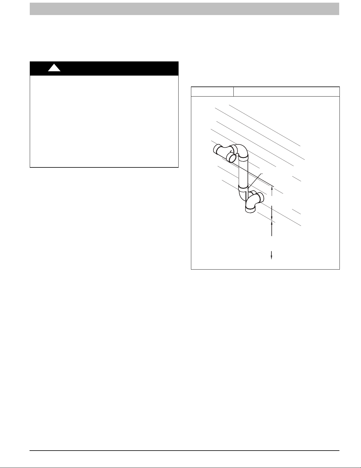
INSTALLATION INSTRUCTIONS Gas Furnace: (F/G)9MXT, (F/G)9MXE
Direct Vent / 2−Pipe System
Direct vent (2−pipe) vent and combustion air pipes must
terminate outside the structure. See Figure 65 for references to
vent clearances required by National code authorities.
Allowable vent and combustion air terminations are shown in
Figure 52.
!
WARNING
CARBON MONOXIDE POISONING HAZARD
Failure to follow the instructions outlined in Locating the Vent
Termination for each appliance being placed into operation
could result in carbon monoxide poisoning or death.
For all venting configurations for this appliance and other gas
appliances placed into operation for the structure, provisions
for adequate combustion, ventilation, and dilution air must be
provided in accordance with:
U.S.A. Installations: Current edition of Section 9.3 NFPA
54/ANSI Z223.1, Air for Combustion and Ventilation and
applicable provisions of the local building codes.
Canadian Installations: Current edition of Part 8 of
CAN/CSA−B149.1. Venting Systems and Air Supply for
Appliances and all authorities having jurisdiction.
Ventilated Combustion Air
The vent pipe for a Ventilated Combustion Air System must
terminate outdoors. See Figure 65 for references to vent
clearances required by National code authorities. Allowable
vent terminations are shown in Figure 53. The combustion air
pipe terminates in a well−ventilated attic or crawl space. Follow
the clearances as shown in Figure 63 and Figure 64.
The combustion air pipe cannot terminate in attics or crawl
spaces that use ventilation fans designed to operate in the
heating season. If ventilation fans are present in these areas,
the combustion air pipe must terminate outdoors as a Direct
Vent System.
Non−Direct Vent / 1−Pipe System
The vent pipe for a Non Direct Vent (1−pipe) system must
terminate outdoors. See Figure 66 for references to vent
clearances required by National code authorities. Allowable
vent terminations are shown in Figure 53.
A combustion air inlet pipe to the outdoors is not required for a
Non−Direct Vent System. A 12−in. long section of pipe with a
tight radius 2−in. (51 mm) 90 degree elbow is required to be
attached to the furnace. See Figure 49 and Figure 51. This
short inlet air pipe helps to ensure inlet air pipe away from
occupants. An extra elbow and/or 5 ft. (1.5 M) of pipe may be
used to accomplish the sound attenuation function.
Termination Requirements for the
Provinces of Alberta and Saskatchewan
The Provinces of Alberta and Saskatchewan require a
minimum unobstructed distance of 4 ft. (1.2 M) from the
foundation to the property line of the adjacent lot for vent
termination of any appliance with an input over 35,000 btuh. If
there is less than 4 ft. (1.2 M) of unobstructed distance to the
property line of the adjacent lot, no type of vent termination is
permitted for appliances with inputs greater than 35,000 btuh.
There are no additional restrictions on unobstructed distances
greater than 8 ft. (2.4 M). All single, two-pipe and concentric
vents may be used, providing all other Code and
manufacturer’s requirements in these instructions are adhered
to. Refer to the appropriate Vent Termination section above for
locating the vent termination .
If the unobstructed distance from the foundation to the property
line of the adjacent lot is no less than 4 ft. (1.2 M) and no
greater than 8 ft. (2.4 M), it will be necessary to re-direct the
flue gas plume. In this situation, a concentric vent kit cannot be
used. A 2-pipe termination (or single pipe termination when
permitted) that re-directs the flue gas away by use of an elbow
or tee, certified to ULC S636
must be used. (See Figure 49 and Figure 51)
The concentric vent kit currently cannot be modified to attach
an elbow to the vent portion of the rain cap. A tee attached to
the rain cap could potentially direct the flue gas plume toward
the intake air stream and contaminate the incoming combustion
air for the furnace.
Refer to Figure 49 and Figure 51 for terminations approved for
use in Alberta and Saskatchewan.
from the adjacent property line
Figure 49 Tee at Termination Outlet
OPTIONAL TERMINATION
BRACKET FOR 2-PIPE
TERMINATIONS
12 IN. (305 MM) MIN.
SEPARATION BETWEEN
BOTTOM OF COMBUSTION
AIR AND BOTTOM OF VENT.
12-IN. (305 MM)
ABOVE ANTICIPATED
SNOW LEVEL
A13078A
440 01 4005 05 45
Specifications subject to change without notice.

INSTALLATION INSTRUCTIONS Gas Furnace: (F/G)9MXT, (F/G)9MXE
Figure 50
EXAMPLE FOR
UPFLOW INSTALLATIONS.
MAY BE APPLIED TO
OTHER CONFIGURATIONS.
Sample Inlet Air Pipe Connection
for Polypropylene Venting Systems
A12220
Figure 51 Vent Terminations
OPTIONAL
BRACKET
COUPLING
(ELBOW PARALLEL TO WALL)
COMBUSTION-AIR
12 IN. (305 MM) MIN. SEPARATION
BETWEEN BOTTOM OF
COMBUSTION AIR AND
BOTTOM OF VENT.
MAINTAIN 12 IN. (305 MM)
CLEARANCE ABOVE
HIGHEST ANTICIPATED
SNOW LEVEL OR GRADE,
WHICHEVER IS GREATER.
A13078B
EXHAUST
OVERHANG
CLEARANCE TO OVERHANG PER CODE
12 IN.
(305 MM) MIN. GROUND
LEVEL OR ANTICIPATED SNOW LEVEL
A13078C
46 440 01 4005 05
Specifications subject to change without notice.

INSTALLATION INSTRUCTIONS Gas Furnace: (F/G)9MXT, (F/G)9MXE
Figure 52 Combustion Air and Vent Pipe Termination for Direct Vent (2−Pipe) System
Vertical separation between
combustion air and vent
8 ¾ in. (222mm) for 3 in.(76mm)
6 ¾ in. (172mm) for 2in. (51mm)
Maintain 12 in. (305mm)
min. Clearance above
highest anticipated snow
level maximum of 24 in.
(614mm) above roof
18 in. Maximum
(457mm)
0
90
At least 36 in.
(914mm)
At least 36 in.
(914mm)
Roof Termination (Preferred)
Note:
“A” denotes 0 To 2 in. (51mm)
A
Between the first 2 vents Third
vent (and fourth vent, if used)
must be 36 in. Away (914mm)
Abandoned masonry used
as raceway (per code)
Concentric Vent and Combustion Air
Side Termination
12 in. Min from
overhang or
roof (Typ.)
A
12 in. (305mm) separation
between bottom of com−
bustion air and bottom of
vent (Typ.)
Maintain 12 in. (305mm) min.
Clearance above highest an−
ticipated snow level or grade
whichever is greater (Typ.)
At least 36 in.
(914mm)
Concentric Vent and Combustion Air
Roof Termination (preferred)
A
At least 36 in.
(914mm)
Note:
“A” denotes 0 To 2 in. (51mm)
Between the first 2 vents Third
vent (and fourth vent, if used) must
be 36 in . Away (914mm)
A
Note:
36−in. separation between
pairs of inlets only required
for direct−vent systems
Maintain 12 in. (305mm) min. Clearance
above highest anticipated snow level
maximum of 24 in. (614mm) above roof
1 in. (25mm) maximum
(Typ.) from wall to inlet
12 in. From Overhang
or roof (Typ.)
A
Maintain 12 in. (305mm) min. Clear−
At least 36 in.
(914mm)
Side wall termination of
less than 12 in. (305mm)
above highest snow level
ance above highest anticipated snow
level or grade whichever is greater
(Typ.)
L12F044
Figure 53 Vent Pipe Termination for Non−Direct Vent and Ventilated Combustion Air System
Roof Termination (Preferred)
Ven t
(305mm)
Maintain 12 in .
minimum clearance
above highest anticipated
snow level maximum of
24 in. (610mm) above roof.
Abandoned masonry
used as raceway
(per code)
12 in. min. (305 mm)from
overhang or roof
Sidewall Termination
with Straight Pipe (preferred)
Maintain 12 in. (305mm)
minimum clearance
above highest anticipated
snow level or grade
whichever is greater
90°
Side wall termination
with 2 elbows (preferred)
12 in. (305 mm) min. from
overhang or roof
Maintain 12 in. (305mm)
minimum clearance
above highest anticipated
snow level or grade
whichever is greater.
6 in. (152mm) minimum clearance
between wall and end of vent pipe.
10 in. (254mm) maximum pipe length
A05091
440 01 4005 05 47
Specifications subject to change without notice.

INSTALLATION INSTRUCTIONS Gas Furnace: (F/G)9MXT, (F/G)9MXE
Size the Vent and Combustion Air Pipes
General
Vent and
Combustion Air
Pipe Diameters
1−1/2−in. (38 mm) No Ye s No No No 2−in. (51 mm)
2−in. (51 mm) No Yes No No No 2−in. (51 mm)
2−1/2−in. (64 mm) No No No Yes No
3−in. (76−mm) No No No Yes No 3−in. (76 mm)
4−in. (102 mm) No No No Yes Yes 3−in. (76 mm)
Furnace combustion air and vent pipe connections are sized
for 2-in. (50 mm ND) PVC/ABS DWV pipe. The combustion air
and vent pipe connections also accommodate 60mm
polypropylene venting systems with outside diameters of
approximately 60 mm (2−3/8 inches). Any pipe diameter
change should be made outside furnace casing in vertical pipe.
Any change in diameter to the pipe must be made as close to
the furnace as reasonably possible (see Figure 54).
The Maximum Vent Length for the vent pipe and combustion air
pipe (when used) equals the Maximum Equivalent Vent Length
(MEVL) in Table 14, minus the number of fittings multiplied by
the deduction for each type of fitting used from Table 15.
1−1/2−in.
(38 mm)
Combustion−Air and Vent Pipe
Figure 54
Diameter Transition Location and
Elbow Configuration
FURNACE
NOT IN
HORIZONTAL
SECTION
PIPE DIAMENTER
TRANSITION IN
SECTION
Approved Two−Pipe Termination Fittings
2−in.
(51 mm)
2−1/2−in.
(64 mm)
3−in.
(76−mm)
Combustion Air Inlet Moisture Trap
To prevent moisture from trickling into the furnace vestibule, a
trap can be installed in the intake air pipe near the furnace.
Connecting a drain line to the trap is recommended as trace
amounts of moisture will evaporate into the intake air stream. If
the combustion air inlet is located near a moisture exhaust
duct, or there are other concerns of excessive moisture being
drawn into the combustion air inlet, it is encouraged to connect
a drain line to the trap.
The trap can be constructed from a running tee of the same
diameter of the intake air pipe with EITHER a removable cap
attached to a 6-inch long pipe connected to the tee or the
External vent Trap Kit to help prevent contaminants from
entering the furnace. See Figure 55.
The External Vent Trap Kit accessory may be used as a trap for
the combustion air inlet pipe if a large amount of moisture must
be removed. The drain line may be connected to the same
drain as the furnace condensate and the evaporator coil
condensate line ONLY if the inlet air trap drain and the
evaporator coil drain empty into an open segment of pipe
above the drain, See Figure 13. When using the External Vent
Trap Kit, refer to those instructions for proper drain
connections.
The tee may also be connected to the intake air pipe on the
side of the casing. See Figure 55.
In any configuration, it will be necessary to add the equivalent
length of the tee (15 feet/5 M) to the Total Equivalent Vent
A93034
Length of the venting system.
4−in.
(102 mm)
Allowable
Concentric Vent
2−in. (51 mm)
3−in. (76 mm)
Kit
NOTICE
NOTICE
OPTIONAL CONFIGURATION FOR COMBUSTION AIR INLET PIPE
In applications where there is a risk of excessive moisture
entering the combustion air inlet pipe, a moisture trap may be
added to the inlet pipe to help prevent moisture from entering
the furnace from the combustion air inlet pipe. See Figure 55.
When sizing venting systems, the equivalent length of the
optional moisture trap (15 feet/5 M) must be taken into account
48 440 01 4005 05
Specifications subject to change without notice.
ADDITIONAL INFORMATION FOR POLYPROPYLENE
VENTING SYSTEMS
Polypropylene venting systems include flexible vent pipe.
These flexible vent pipes have a different equivalent vent
length than straight sections of PVC/ABS DWV vent pipe. Be
sure to make the appropriate deductions from the Maximum
Equivalent Vent Length (MEVL), or additions to the Total
Equivalent Vent Length (TEVL), when applying flexible vent
pipes in polypropylene venting systems. See the polypropylene vent system manufacturer’s installation instructions for
details.
When using metric-sized venting systems, use these equivalencies for obtaining the proper MEVL from the Tables:
Use 2” Vent Tables for 60mm (o.d.) vent systems
Use 3” Vent Tables for 80mm (o.d.) vent systems
Use 4” Vent Tables for 100mm (o.d.) vent systems

INSTALLATION INSTRUCTIONS Gas Furnace: (F/G)9MXT, (F/G)9MXE
The measured length of pipe used in a single or 2−pipe
termination is included in the total vent length. Include
deductions from the Maximum Equivalent Vent Length (MEVL)
contained in the Venting Tables for elbows and flexible vent
pipe. Factory accessory concentric vent terminations, or pipe
lengths and elbows used for “standard” vent terminations (see
vent termination figures associated with Table 14) do not
require a deduction from the Maximum Equivalent Vent Length.
Include a deduction for a Tee when used for Alberta and
Saskatchewan terminations.
NOTE: Polypropylene venting systems MAY require additional
deductions from the MEVL, or additions to the TEVL, for vent
terminations and flexible pipe sections. See the polypropylene
venting system manufacturer’s instructions for details on
equivalent lengths of vent terminations and flexible vent pipes,
and for calculating total vent lengths.
To calculate the Total Equivalent Vent Length (TEVL) of the
venting system:
1. Measure the individual distance from the furnace to the
termination for each pipe.
2. Count the number of elbows for each pipe.
3. For each pipe, multiply the number of elbows by the
equivalent length for the type of elbow used. Record the
equivalent length of all the elbows for each pipe.
4. If a Tee is used on the termination (Alberta and
Saskatchewan, when required), record the equivalent
length of the Tee used.
5. Calculate Total Equivalent Vent Length by adding the
equivalent lengths of the fittings to the lengths of the
individual vent and combustion air pipes.
6. When using polypropylene venting systems with flexible
vent pipes, perform adjustments for the equivalent length
of the flexible vent pipe to the calculated total equivalent
venting system length. See the polypropylene vent
system manufacturer’s instructions for details.
7. Select a diameter of vent pipe from Table 14 and note
the Maximum Equivalent Vent Length (MEVL) shown for
that application for that specific furnace input size.
Compare the Total Equivalent Vent Length (TEVL) to the
MEVL:
a. If the Total Equivalent Vent Length is shorter than the
Maximum Equivalent Vent Length for the diameter of
pipe chosen, then that diameter of pipe selected may
be used.
b. If the Total Vent Length is longer than the Maximum
Equivalent Vent Length for the diameter of pipe
chosen, that diameter pipe MAY NOT be used for
venting the furnace. Try the next larger diameter pipe.
NOTE: If the calculated Total Equivalent Vent Lengths results
in different diameter pipes for the vent and combustion air,
select the larger diameter for both pipes.
NOTE: If the Maximum Vent Length for diameter of the pipe
selected is longer than the measured length and the equivalent
length of all the fittings and terminations (TEVL), recalculate
Total Equivalent Vent Length using the next smaller diameter. If
the Maximum Vent Length is still longer than the longer TEVL
of the vent pipe or combustion air pipe, then that diameter of
pipe selected may be used.
When installing vent systems with pipe lengths of 10 ft. (3.0 M)
or less, use the smallest allowable pipe diameter. Using pipe
size greater than required for short venting systems may result
in loss of efficiency, incomplete combustion, flame disturbance,
or flame sense lockout.
For vent systems longer than 10 ft. (3.0 M), any larger diameter
shown in Table 14 for that size model may be used.
440 01 4005 05 49
Specifications subject to change without notice.

INSTALLATION INSTRUCTIONS Gas Furnace: (F/G)9MXT, (F/G)9MXE
Figure 55 Recommended Combustion Air Inlet Moisture Trap
Tee
Dry Well
Cap
(water tight
and removable)
A
TO CODE−APPROVED DRAIN OR CONDENSATE PUMP
Recommend “T” fitting with 4−inch minimum height standpipe (A) of same diameter or larger extending upward.
A
A
Tee
Dry Well
Tee
Cap
(water tight
Dry Well
and removable)
Representative drawing only, some models may vary in appearance.
Cap
(water tight
and removable)
A170134
Combustion Air and Vent Piping Insulation
Guidelines
NOTE: Use closed cell, neoprene insulation or equivalent.
The vent pipe may pass through unconditioned areas. The
amount of exposed pipe allowed is shown in Table 16.
1. Using winter design temperature (used in load
calculations), find appropriate temperature for your
application and furnace model.
2. Determine the amount of total and exposed vent pipe.
3. Determine required insulation thickness for exposed pipe
length(s).
50 440 01 4005 05
Specifications subject to change without notice.
4. When combustion air inlet piping is installed above a
suspended ceiling, the pipe MUST be insulated with
moisture resistant insulation such as Armaflex or other
equivalent type of insulation.
5. Insulate combustion air inlet piping when run in warm,
humid spaces.
6. Install the insulation per the insulation manufacturer’s
installation instructions.
NOTE: Pipe length (ft / M) specified for maximum pipe lengths
located in unconditioned spaces (See Table 16) cannot exceed
total allowable pipe length as calculated from Table 14.

INSTALLATION INSTRUCTIONS Gas Furnace: (F/G)9MXT, (F/G)9MXE
Configure the Furnace
!
CARBON MONOXIDE POISONING HAZARD
Failure to follow this warning could result in personal injury or
death.
To route the vent pipe and combustion air pipe through the
furnace, the manufacturer supplied kit must be used. Failure
to properly seal the blower compartment from the furnace
vestibule could result in the circulation of carbon monoxide
throughout the structure. The vent pipe and combustion air
pipe must be a continuous pipe while passing through the
blower compartment. Seals supplied in this kit must be
installed per the instructions provided. Follow all procedures
outlined in these instructions.
WARNING
Near Furnace Vent Connections
Offsets in the vertical portion of the vent pipe should be made
with 45 degree elbows instead of 90 degree elbows. Short
horizontal runs of vent pipe are difficult to pitch correctly and
may trap water in the vent pipe. Trapped water in the vent pipe
may result in nuisance pressure switch tripping.
Figure 56 Near Furnace Vent Connections
Install the Vent and Combustion Air Pipes
With the furnace installed in the required position, remove the
desired knockouts from the casing. It will be necessary to
remove one knockout for the vent pipe and the other knockout
for the combustion air connection. (See Figure 12)
Use a flat blade screwdriver and tap on the knockout on
opposite sides, where the knockout meets the casing. Fold the
knockout down with duct pliers and work the knockout back
and forth until it is removed. Trim any excess metal from the
knockout with tin snips.
The vent elbow can be rotated to the required location on the
casing if necessary. See Figure 57 to rotate the vent elbow:
1. Loosen the clamp on the inlet of the vent elbow attached
to the inducer.
2. Rotate the vent elbow to the required position. There are
rounded notches in the vent elbow to align it with the
inducer for each orientation.
3. Tighten the clamp around the vent elbow. Torque the
clamp to 15 lb-in. See Figure 58 through Figure 61.
Figure 57 Inducer Vent Elbow − PSC
Avoid short horizontal offsets with 90
deg. Elbows. Short offsets can be
difficult to slope and may trap condensate.
Use 45 deg. Elbows where
possible, to ensure condensate drainage.
Slope vent pipe back to the
furnace at least ¼” per foot
L14F020A
PSC INDUCER ASSEMBLY
TABS ON THE INDUCER OUTLET RESTRICTOR SNAP
INTO THE SLOTS AT THE OUTL ET OF THE INDUCER
SEE MAXIMUM EQUIVALENT VENT LENGTH TABLE
FOR USAGE:
A13075A
A170006B
L14F020B
440 01 4005 05 51
Specifications subject to change without notice.

INSTALLATION INSTRUCTIONS Gas Furnace: (F/G)9MXT, (F/G)9MXE
Figure 58 Upflow Configurations
UPFLOW LEFT − VENT CONFIGURATION
Representative drawing only, some models may vary in appearance.
Figure 59 Downflow Configurations
A11309
DOWNFLOW LEFT − VENT CONFIGURATION
Representative drawing only, some models may vary in appearance.
A11311
UPFLOW RIGHT − VENT CONFIGURATION
Representative drawing only, some models may vary in appearance.
UPFLOW VERTICAL − VENT CONFIGURATION
Representative drawing only, some models may vary in appearance.
* See NOTES following figures.
A11308
A11310
DOWNFLOW RIGHT − VENT CONFIGURATION
Representative drawing only, some models may vary in appearance.
DOWNFLOW VERTICAL − VENT CONFIGURATION
Requires Accessory Internal Vent Kit
See Specification Sheets for current kit number
Representative drawing only, some models may vary in appearance.
* See NOTES following figures.
A11312
L11F063
52 440 01 4005 05
Specifications subject to change without notice.

INSTALLATION INSTRUCTIONS Gas Furnace: (F/G)9MXT, (F/G)9MXE
Figure 60 Horizontal Left Configurations
HORIZONTAL LEFT − VERTICAL VENT CONFIGURATION
Representative drawing only, some models may vary in appearance.
Figure 61 Horizontal Right Configurations
HORIZONTAL RIGHT − VERTICAL VENT CONFIGURATION
Representative drawing only, some models may vary in appearance.
HORIZONTAL LEFT − LEFT VENT CONFIGURATION
Representative drawing only, some models may vary in appearance.
HORIZONTAL LEFT − RIGHT VENT CONFIGURATION*
* Requires accessory Internal Vent Kit
Representative drawing only, some models may vary in appearance.
* See NOTES following figures.
HORIZONTAL RIGHT − LEFT VENT CONFIGURATION
Representative drawing only, some models may vary in appearance.
HORIZONTAL RIGHT − RIGHT VENT CONFIGURATION
Representative drawing only, some models may vary in appearance.
* See NOTES following figures.
440 01 4005 05 53
Specifications subject to change without notice.

INSTALLATION INSTRUCTIONS Gas Furnace: (F/G)9MXT, (F/G)9MXE
NOTES:
1. Attach vent pipe adapter with gasket to furnace casing.
2. Align notches in rubber coupling over standoffs on
adapter. Slide clamps over the coupling.
3. Slide vent pipe through adapter and coupling into vent
elbow.
4. Insert vent pipe into vent elbow.
5. Torque all clamps 15−lb.−in.
6. Attach combustion air pipe adapter with gasket to
furnace.
7. Attach combustion air pipe to adapter with silicone. Pilot
drill a 1/8−in. Hole in adapter and secure with a #7 x
1/2−in. Sheet metal screw.
Installing the Vent Pipe Adapter and
Combustion Air Pipe Adapter
!
CARBON MONOXIDE POISONING HAZARD
Failure to follow this warning could result in personal injury or
death.
To route the vent pipe and combustion air pipe through the
furnace, the manufacturer supplied kit must be used. Failure
to properly seal the blower compartment from the furnace
vestibule could result in the circulation of carbon monoxide
throughout the structure. The vent pipe and combustion air
pipe must be a continuous pipe while passing through the
blower compartment. Seals supplied in this kit must be
installed per the instructions provided. Follow all procedures
outlined in these instructions.
!
CARBON MONOXIDE POISONING HAZARD
Failure to follow this warning could result in personal
injury or death.
DO NOT use cement to join polypropylene venting
systems. Follow the polypropylene venting system
manufacturer’s instructions for installing polypropylene
venting systems.
NOTE: The rubber coupling that attaches to the vent pipe
adapter must be used. The adapter seals the vent pipe to the
casing and reduces the strain on the vent elbow attached to the
inducer.
1. Apply the gaskets to the vent pipe and combustion air
pipe adapters. If supplied, remove and discard round
center “slug” from interior of gasket.
NOTE: The vent pipe adapter can be distinguished from the
inlet pipe adapter by the absence of an internal pipe-stopping
ring. The vent pipe can pass through the vent pipe adapter; it
cannot pass through the inlet pipe adapter.
2. Align the screw holes in the plastic vent pipe adapter with
the dimples in the casing.
3. Pilot drill the screw holes for the adapter in the casing
and attach the vent pipe adapter to the furnace with
sheet metal screws
WARNING
WARNING
See Figure 45.
4. Slide the end of the rubber vent coupling with notches in
it over the standoffs on the vent pipe adapter.
5. Insert a length of vent pipe through the coupling into the
outlet of the vent elbow.
6. Tighten the clamp around the outlet of the vent elbow.
Torque the clamp to 15 lb−in.
NOTICE
The following instructions are for PVC/ABS DWV vent piping,
only. DO NOT USE THESE TECHNIQUES FOR
POLYPROPYLENE VENT PIPING SYSTEMS. See the
polypropylene vent system manufacturer’s instructions for
installing polypropylene venting systems.
Install the remaining vent and combustion air pipes as shown
below. It is recommended that all pipes be cut, prepared, and
preassembled before permanently cementing any joint.
1. Working from furnace to outside, cut pipe to required
length(s).
2. De−burr inside and outside of pipe.
3. Chamfer outside edge of pipe for better distribution of
primer and cement.
4. Clean and dry all surfaces to be joined.
5. Check dry fit of pipe and mark insertion depth on pipe.
6. Insert the vent pipe into the vent elbow.
7. Torque clamp on vent elbow 15 lb−in.
8. Torque clamp on vent coupling 15 lb−in.
9. Insert the combustion air pipe into the adapter.
10. Pilot drill a screw hole through the adapter into the
combustion air pipe and secure the pipe to the adapter
with sheet metal screws. DO NOT DRILL INTO
POLYPROPYLENE VENT PIPES. Use an optional
accessory vent coupling, if needed.
11. Seal around the combustion air pipe with silicone or foil
tape. SILICONE SEALERS MAY NOT BE
APPROPRIATE FOR POLYPROPYLENE VENT
SYSTEMS. SEE POLYPROPYLENE VENT SYSTEM
MANUFACTRUER’S INSTRUCTIONS.
12. After pipes have been cut and preassembled, apply
generous layer of cement primer to pipe fitting socket
and end of pipe to insertion mark. Quickly apply
approved cement to end of pipe and fitting socket (over
primer). Apply cement in a light, uniform coat on inside of
socket to prevent buildup of excess cement. Apply
second coat. DO NOT CEMENT POLYPROPYLENE
FITTINGS.
13. While cement is still wet, twist pipe into socket with
1/4−in. turn. Be sure pipe is fully inserted into fitting
socket.
14. Wipe excess cement from joint. A continuous bead of
cement will be visible around perimeter of a properly
made joint.
15. Handle pipe joints carefully until cement sets.
16. Horizontal portions of the venting system shall be
supported to prevent sagging. Space combustion air
piping and vent piping hangers as shown in the table
below. Support pipes using perforated metal hanging
strap or commercially available hangers or straps
designed to support plastic pipe.
54 440 01 4005 05
Specifications subject to change without notice.

INSTALLATION INSTRUCTIONS Gas Furnace: (F/G)9MXT, (F/G)9MXE
Hanger Spacing
Diameter
1 1/2−in. 3−ft. 2 1/2−ft. 3−ft. 3−ft. 3.25−ft.
38−mm 914−mm 762−mm 914−mm 914−mm 1000 mm
2−in. 3−ft. 3−ft. 3−ft. 3−ft. 3.25−ft.
51−mm 914−mm 914−mm 914−mm 914−mm 1000 mm
2 1/2−in. 3 1/2−ft. 3−ft. 3 1/2−ft. 3 1/2−ft. 3.25−ft.
64−mm 1067−mm 914−mm 1067−mm 1067−mm 1000 mm
3−in. 3 1/2−ft. 3−ft. 3 1/2−ft. 3 1/2−ft. 3.25−ft.
76−mm 1067−mm 914−mm 1067−mm 1067−mm 1000 mm
4−in. 4−ft. 3 1/2−ft. 4−ft. 4−ft. 3.25−ft.
102−mm 1219−mm 1067−mm 1219−mm 1219−mm 1000 mm
PVC Sch 40 SDR 21 & 26 ABS CPVC Polypropylene
! CAUTION
FURNACE RELIABILITY HAZARD
Failure to follow this caution may result in nuisance short
cycling, frozen vent termination, and/or no heat.
Slope the vent and combustion air piping downward towards
furnace at a minimum of 1/4−in. per linear ft. of pipe.
17. Slope the vent and combustion air piping and downward
towards furnace. A minimum slope of at least 1/4 in. per
linear ft.(1 in. per 4 ft.) with no sags between hangers is
required. See Caution Box below.
18. Complete the vent and combustion air pipe installation
by connecting to the concentric vent or by installing the
required termination elbows as shown in Figure 52 and
Figure 53, Alberta Figure 49 and Figure 51. For
ventilated combustion air terminations, refer to Figure 63
and Figure 64.
19. Use appropriate methods to seal openings where
combustion air pipe and vent pipe pass through roof or
sidewall.
!
CARBON MONOXIDE POISONING HAZARD
Failure to follow this warning could result in personal injury or
death.
DO NOT use cement to join polypropylene venting systems.
Follow the polypropylene venting system manufacturer’s
instructions for installing polypropylene venting systems.
WARNING
Material
4. Clean and prime the end of the pipe that is flush with the
vent adapter with a primer that is appropriate for the type
of pipe being used.
5. Re−insert the pipe through the casing into the vent
elbow.
6. Tighten the clamp around the outlet of the vent elbow.
Torque the clamp to 15 lb−in.
7. Apply cement to the end of the pipe and to the inside of
the plastic vent adapter.
8. Slide the adapter over the vent pipe and align the screw
holes in the adapter with the dimples in the furnace
casing.
9. Pilot drill 1/8−in. screw holes for the adapter in the casing
and secure the adapter to the furnace with sheet metal
screws.
10. Loosen the clamps on the rubber vent coupling.
11. Slide the end of the coupling with notches in it over the
standoffs in the vent pipe adapter.
12. Tighten the clamp of the coupling over the vent pipe
adapter. Torque the lower clamp around the vent pipe
adapter to 15 lb−in.
13. Pilot drill a 1/8−in. hole in the combustion air pipe
adapter.
14. Complete the vent and combustion air pipe as shown in
“Install the Vent and Combustion Air Pipe”
NOTICE
FOR POLYPROPYLENE VENTING SYSTEMS
When using polypropylene venting systems, all venting materials used, including the vent terminations, must be from the
same manufacturer.
Optional Installation of the Vent Pipe
NOTE: DO NOT USE THIS TECHNIQUE FOR
POLYPROPYLENE VENTING SYSTEMS.
This option provides a disconnect point for the vent pipe. The
vent pipe must be cemented to the plastic vent pipe adapter to
maintain a sealed vestibule. See Figure 46 and Figure 47
1. Insert a length of vent pipe through the casing into the
outlet of the vent elbow.
2. Slide the plastic vent pipe adapter over the length of the
vent pipe down to the furnace casing. Mark the pipe
where it is flush with the outlet of the adapter.
3. Remove the pipe from the furnace and the adapter and
cut off any excess pipe.
CARBON MONOXIDE POISONING HAZARD
Failure to follow this warning could result in personal injury or
death.
DO NOT use cement to join polypropylene venting systems.
Follow the polypropylene venting system manufacturer’s
instructions for installing polypropylene venting systems.
! WARNING
440 01 4005 05 55
Specifications subject to change without notice.

INSTALLATION INSTRUCTIONS Gas Furnace: (F/G)9MXT, (F/G)9MXE
Figure 62 Combustion Air Pipe
12" (256mm) minimum
to
60”(1524 mm) or
1 additional elbow maximum
CASING SIDE OR TOP ATTACHMENT
(NON-DIRECT VENT FOR ALL MODELS EXCEPT MODULATING UNLESS
COMBUSTION AIR PIPE
INSTALLED IN ATTIC OR CRAWL SPACE)
A13406
Installing the Vent Termination
Roof Terminations
A roof termination of any type will require a 4-in. (102 mm)
flashing for a 2−in. (50 mm ND) concentric vent or a 5−in. (127
mm) diameter flashing for a 3-in. (80 mm ND) concentric vent
kit. For two-pipe or single pipe vent systems, a flashing for each
pipe of the required diameter will be necessary.
It is recommended that the flashing be installed by a roofer or
competent professional prior to installing the concentric vent.
The terminations can be installed on a flat or pitched roof.
Concentric Vent
Single or multiple concentric vent must be installed as shown in
Figure 52. Maintain the required separation distance between
vents or pairs of vents as shown in Figure 52 and all
clearance shown in Figure 65.
!
CARBON MONOXIDE POISONING HAZARD
Failure to follow this warning could result in personal injury or
death.
DO NOT use cement to join polypropylene venting systems.
Follow the polypropylene venting system manufacturer’s
instructions for installing polypropylene venting systems.
NOTE: Follow the instructions of the vent terminal
manufacturer. These instructions are provided as a reference
only.
Cut one 4−in. (102 mm) diameter hole for 2−in. (50 mm ND) kit,
or one 5−in. (127 mm) diameter hole for 3−in. (80 mm ND) kit in
the desired location.
Loosely assemble concentric vent/combustion air termination
components together using instructions in kit.
Slide assembled kit with rain shield REMOVED through hole in
wall or roof flashing.
NOTE: Do not allow insulation or other materials to accumulate
inside of pipe assembly when installing it through hole.
Disassemble loose pipe fittings. Clean and cement using same
procedures as used for system piping. DO NOT CEMENT
POLYPROPYLENE FITTINGS.
WARNING
Two−Pipe and Single−Pipe Terminations
Single and two pipe vent must be installed as shown in
Figure 52 and Figure 53. Maintain the required separation
distance between vents or pairs of vents as shown in
Figure 52 and Figure 53 and all clearance shown in Figure 65
or Figure 66.
NOTICE
Recommended Support for Vent Terminations
It is recommended that rooftop vent terminations in excess of
36 inches (1.0 M) in vertical length be supported by EITHER the
Direct Vent Termination Kit shown in Table 12 or by
field-supplied brackets or supports fastened to the structure.
Cut the required number of holes in the roof or sidewall for vent
and (when used) combustion air pipes. Sidewall holes for
two-pipe vent terminations should be side-by-side, allowing
space between the pipes for the elbows to fit on the pipes.
Holes in the roof for direct−vent (two−pipe) terminations should
be spaced no more than 18−in. (457 mm) apart to help avoid
vent gas recirculation into combustion air intake.
Termination elbows will be installed after the vent and (if used)
combustion air pipe is installed.
Sidewall Terminations
Concentric Vent
NOTE: Follow the instructions of the vent terminal
manufacturer. These instructions are provided as a reference,
only.
Determine an appropriate location for termination kit using the
guidelines provided in section “Locating The Vent Termination”
in this instruction.
1. Cut one 4−in. diameter hole for 2−in. kit, or one 5−in.
diameter hole for 3−in. kit.
2. Loosely assemble concentric vent/combustion air
termination components together using instructions in kit.
3. Slide assembled kit with rain shield REMOVED through
hole.
NOTE: Do not allow insulation or other materials to accumulate
inside of pipe assembly when installing it through hole.
4. Locate assembly through sidewall with rain shield
positioned no more than 1−in. (25 mm) from wall as
shown in Figure 52.
5. Disassemble loose pipe fittings. Clean and cement using
same procedures as used for system piping. DO NOT
CEMENT POLYPROPYLENE FITTINGS.
Two-Pipe and Single-Pipe Vent Termination
NOTE: Follow the instructions of the vent terminal
manufacturer. These instructions are provided as a reference,
only.
NOTICE
Recommended Support for Vent Terminations
It is recommended that side−wall vent terminations in excess
of 24 inches (0.6 M) in vertical length be supported by
EITHER the Direct Vent Termination Kit in Table 12 or by
field-supplied brackets or supports fastened to the structure.
Determine an appropriate location for termination kit using the
guidelines provided in section “Locating The Vent Termination”
in this instruction.
56 440 01 4005 05
Specifications subject to change without notice.

INSTALLATION INSTRUCTIONS Gas Furnace: (F/G)9MXT, (F/G)9MXE
1. Cut two holes, one for each pipe, of appropriate size for
pipe size being used.
2. Loosely install elbow in bracket (if used) and place
assembly on combustion−air pipe.
3. Install bracket as shown in Figure 49 and Figure 51.
NOTE: For applications using vent pipe option indicated by
dashed lines in Figure 52 and Figure 53, rotate vent elbow 90_
from position.
4. Disassemble loose pipe fittings. Clean and cement using
same procedures as used for system piping. DO NOT
CEMENT POLYPROPYLENE FITTINGS.
(Direct Vent / Two-Pipe System ONLY)
When two or more furnaces are vented near each other, two
vent terminations may be installed as shown in Figure 49 and
Figure 51, but next vent termination, or pair of vent
terminations, must be at least 36−in. (914 mm) away from first
two terminations. It is important that vent terminations be made
as shown in Figure 49 and Figure 51 to avoid recirculation of
gases.
Inducer Outlet Restrictor
To improve efficiency and operation of 26K, 40K, 60K, or 100K
BTUH input models on very short vent systems, an inducer
outlet restrictor is required to be installed on the outlet of the
inducer assembly. The outlet restrictor is shown in the footnote
of Table 14 − Maximum Equivalent Vent Length. The outlet
restrictor for 26K and 40K models is shipped in the loose parts
bag. See Table 14 for usage, part numbers and sourcing of
26K, 40K, 60K and 100K inducer outlet restrictors.
To determine if the outlet restrictor is required, see Table 14.
Failure to use an outlet restrictor on the 40K model when
required may result in flame disturbance or flame sense
lockout.
To install the outlet restrictor:
1. Remove the vent elbow from the inducer outlet
2. Align the lock tabs on the outlet restrictor with the slots
on inside outlet of the inducer assembly.
3. Snap the outlet restrictor in place.
4. Re-install the vent elbow
5. Torque vent elbow clamp 15 lb−in.
440 01 4005 05 57
Specifications subject to change without notice.
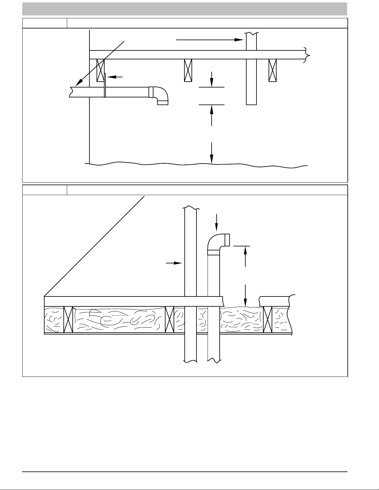
INSTALLATION INSTRUCTIONS Gas Furnace: (F/G)9MXT, (F/G)9MXE
Figure 63 Crawl Space Vent Termination
Ventilated Combustion
Air intake pipe
Pipe hangar
3” (76 mm)
Ventilated Combustion Air
intake termination in crawl
space
Figure 64 Attic Vent Termination
Vent through
roof flashing
12” (305 mm)
CRAWL SPACE
Ventilated Combustion
Air intake pipe
L11F016A
12” (305 mm) min. above
higest level of insulation
ATTIC
58 440 01 4005 05
Specifications subject to change without notice.
L11F016B

INSTALLATION INSTRUCTIONS Gas Furnace: (F/G)9MXT, (F/G)9MXE
Figure 65 Direct Vent Termination Clearance
V
V
25−24−65−2
NOTE: The following is based upon National codes for gas appliances, and is provided as a reference.
Refer to Local codes which may supersede these standards and/or recommendations.
Item Clearance Description
Clearance above grade, veranda, porch, deck, balcony or
A
B Clearance to a window or door that may be opened
C Clearance to a permanently closed window
Vertical clearance to a ventilated soffit located above the
terminal within a horizontal distance of 2 feet (61 cm) from
D
E Clearance to an unventilated soffit
F Clearance to an outside corner
G Clearance to an inside corner
Clearance to each side of the centerline extended above
H
J
K Clearance to a mechanical air supply inlet 6 ft. (1.8 M) 3ft. (.9 M) above if within 10 ft. (3 M) horizontally
L Clearance under a veranda, porch, deck, or balcony
M
N
0 Clearance from a plumbing vent stack 3 ft. (.9 M) 3 ft. (.9 M)
P
u greater than, w greater than or equal to, t less than, v less than or equal to
electrical meter or gas service regulator assembly
I Clearance to service regulator vent outlet 3ft. (.9 M) See Note 4.
Clearance to non—mechanical air supply inlet to building or
the combustion air inlet to any other appliance
Clearance to each side of the centerline extended above or
below vent terminal of the furnace to a dryer or water heater
vent, or other appliance's vent intake or exhaust
Furnace combustion air intake clearance to a water heater
vent, dryer vent or other types of appliance exhausts.
Clearance above paved sidewalk or paved driveway located
anticipated snow level
the centerline of the terminal
on public property
12 in. (305 mm) for appliances >10,000 Btuh (3 kW)
36 in. (914 mm) for appliances >100,000 Btuh (30 kW)
For clearances not specified in ANSI Z223.1/NFPA 54 or CAN/CSA B149.1, clearances shall be in accordance with local
12 in. (305 mm) for appliances >10,000 Btuh(3 kW)
36 in. (914 mm) for appliances >100,000 Btuh (30 kW)
Permitted only if veranda, porch, deck, or balcony is fully open on a
Vent shall not terminate above a sidewalk or paved driveway that is
located between two single family dwellings and serves both
Canadian Installations
(per CAN/CSA B149.1)
12 in. (305 mm)
18 in. (457 mm) above roof surface.
and </=100,000 Btuh ( 30 kW),
installation codes and the requirements of the gas supplier and the manufacturer's installation instructions.
3 ft. (.9 M) within 15 ft. (4.6 M)
above the meter/regulator assembly.
and </= 100,000 Btuh ( 30 kW),
12 in. (305 mm).
minimum of two sides beneath the floor.
12 in. (305 mm) 12 in. (305 mm)
3 ft. (.9 M) 3 ft. (.9 M)
7 ft. (2.1 M)
dwellings.
Notes:
1. In accordance with the current CAN/CSA B149.1, Natural Gas and Propane Installation Code.
2. In accordance with the current ANSI Z223.1/NFPA 54, National Fuel Gas Code
3. NOTE: This table is based upon National codes for gas appliances, and are provided as a reference.
Refer to Local codes which may supersede these standards and/or recommendations.
4. For clearances not specified in ANSI Z223.1/NFPA 54 or CAN/CSA B 149.1, clearances shall be in accordance with local installation codes and the requirements of the
gas supplier and the manufacturer's installation instructions.
5. When locating vent terminations, consideration must be given to prevailing winds, location, and other conditions which may cause recirculation of the combustion products
of adjacent vents. Recirculation can cause poor combustion, inlet condensate problems, vent termination icing, and/or accelerated corrosion of the heat exchangers.
6. Design and position vent outlets to avoid ice buildup on and moisture damage to surrounding surfaces.
7. The vent for this appliance shall not terminate:
a. Near soffit vents of crawl space vents or other areas where condensate or vapor could create a nuisance or hazard or property damage; or
b. Where condensate vapor could cause damage or could be detrimental to the operation of regulators, relief valves, or other equipment.
8. Avoid venting under a deck or large overhang. Recirculation could occur and cause performance or system problems. Ice buildup may occur.
440 01 4005 05 59
Specifications subject to change without notice.
(1 )
(per ANSI Z223.1/NFPA 54)
9 in. (229 mm) for appliances >10,000 Btuh (3 kW)
and </= 50,000 Btuh ( 15 kW),
12 in. (305 mm) for appliances >50,000 Btuh (15kW)
Manufacturer's Recommendation: See Notes 38.
3 ft. (.9 M) within 15 ft. (4.6 M)
above the meter/regulator assembly.
9 in. (9 mm) for appliances >10,000 Btuh (3 kW)
and </= 50,000 Btuh (15 kW),
12 in.(305 mm) for appliances >50,000 Btuh (15kW)
Manufacturer's Recommendation: See Notes 38.
Manufacturer's Recommendation: See Notes 38.
U.S. Installations
12 in. (305 mm)
See Note 4.
See Note 4.
(2 )

INSTALLATION INSTRUCTIONS Gas Furnace: (F/G)9MXT, (F/G)9MXE
Figure 66 Other than Direct Vent Clearance − Ventilated Combustion Air Option
V
V
25−24−65−2
NOTE: The following is based upon National codes for gas appliances, and is provided as a reference.
Refer to Local codes which may supersede these standards and/or recommendations.
Item
Clearance above grade, veranda, porch, deck, balcony or
A
B Clearance to a window or door that may be opened
C Clearance to a permanently closed window
Vertical clearance to a ventilated soffit located above the
terminal within a horizontal distance of 2 feet (61 cm) from
D
E Clearance to an unventilated soffit
F Clearance to an outside corner
G Clearance to an inside corner
Clearance to each side of the centerline extended above
H
I Clearance to service regulator vent outlet 3ft. (.9 M) See Note 4.
J
K Clearance to a mechanical air supply inlet 6 ft. (1.8 M) 3ft. (.9 M) above if within 10 ft. (3 M) horizontally
L Clearance under a veranda, porch, deck, or balcony
M
N
0 Clearance from a plumbing vent stack 3 ft. (.9 M) 3 ft. (.9 M)
P
u greater than, w greater than or equal to, t less than, v less than or equal to
electrical meter or gas service regulator assembly
Clearance to non—mechanical air supply inlet to building or
the combustion air inlet to any other appliance
Clearance to each side of the centerline extended above or
below vent terminal of the furnace to a dryer or water heater
vent, or other appliance's direct vent intake or exhaust
Clearance above paved sidewalk or paved driveway located
Clearance Description
anticipated snow level
the centerline of the terminal
Clearance to a moisture exhaust duct
(dryer vent, spa exhaust, etc.)
on public property
12 in. (305 mm) for appliances >10,000 Btuh (3 kW)
36 in. (914 mm) for appliances >100,000 Btuh (30 kW)
For clearances not specified in ANSI Z223.1/NFPA 54 or CAN/CSA B149.1, clearances shall be in accordance with local
12 in. (305 mm) for appliances >10,000 Btuh(3 kW)
36 in. (914 mm) for appliances >100,000 Btuh (30 kW)
Permitted only if veranda, porch, deck, or balcony is fully open
Vent shall not terminate above a sidewalk or paved driveway
that is located between two singlefamily dwellings and serves
Canadian Installations
(per CAN/CSA B149.1)
12 in. (305 mm)
18 in. (457 mm) above roof surface.
and </=100,000 Btuh ( 30 kW),
installation codes and the requirements of the gas supplier and the manufacturer's installation instructions.
3 ft. (.9 M) within 15 ft. (4.6 M)
above the meter/regulator assembly.
and </= 100,000 Btuh ( 30 kW),
12 in. (305 mm).
on a minimum of two sides beneath the floor.
12 in. (305 mm) 12 in. (305 mm)
12 in. (305 mm) See Note 4. 12 in. (305 mm) See Note 4.
7 ft. (2.1 M).
both dwellings.
Notes:
1. In accordance with the current CAN/CSA B149.1, Natural Gas and Propane Installation Code.
2. In accordance with the current ANSI Z223.1/NFPA 54, National Fuel Gas Code
3. NOTE: This table is based upon National codes for gas appliances, and are provided as a reference.
Refer to Local codes which may supersede these standards and/or recommendations.
4. For clearances not specified in ANSI Z223.1/NFPA 54 or CAN/CSA B 149.1, clearances shall be in accordance with local installation codes and the requirements of the
gas supplier and the manufacturer's installation instructions.
5. When locating vent terminations, consideration must be given to prevailing winds, location, and other conditions which may cause recirculation of the combustion products
of adjacent vents. Recirculation can cause poor combustion, inlet condensation problems, vent termination icing, and/or accelerated corrosion of the heat exchangers.
6. Design and position vent outlets to avoid ice buildup on and moisture damage to surrounding surfaces.
7. The vent for this appliance shall not terminate:
a. Near soffit vents of crawl space vents or other areas where condensate or vapor could create a nuisance or hazard or property damage; or
b. Where condensate vapor could cause damage or could be detrimental to the operation of regulators, relief valves, or other equipment.
8. These National standards apply to all nondirectvent gas appliances. Contact Local code officials for additional requirements and/or exclusions.
(1 )
Manufacturer's Recommendation: See Notes 38.
(per ANSI Z223.1/NFPA 54)
4ft. (1.2M) below or to the side of the opening,
1 ft (.3M) above the opening.
Manufacturer's Recommendation: See Note 8.
3 ft. (.9 M) within 15 ft. (4.6 M)
above the meter/regulator assembly.
4ft. (1.2M) below or to the side of the opening,
1 ft (.3M) above the opening.
Manufacturer's Recommendation: See Note 8
Manufacturer's Recommendation: See Notes 38.
U.S. Installations
12 in. (305 mm)
See Note 4.
7ft. (2.1M)
(2 )
60 440 01 4005 05
Specifications subject to change without notice.

INSTALLATION INSTRUCTIONS Gas Furnace: (F/G)9MXT, (F/G)9MXE
Table 14 (F/G)9MXE − MAXIMUM EQUIVALENT VENT LENGTH - Feet \ Meters
Note: Maximum Equivalent Vent Length (MEVL) does NOT include elbows or terminations
Use Table 15 − DEDUCTIONS FROM MEVL to determine allowable vent length for each application.
Unit Size 26,000
Pipe Dia.
(in)
02000 70 200 40 155 185
20013000 65 190 35 150 175 95 165 185
30014000 60 175 30 135 160 16 90 155 175 115 155 175
40014500
45015000 125 145 80 145 165 145 160
50016000 50 145 20 120 130 75 140 155 41 100 135 150 140 155 155
60017000 45 135 15 110 120 13 70 130 145
Altitude (feet)
70018000 40 120
80019000 35 110 90 95 5 60 115 125 33 80 110 115 50 115 125 43 120
900110000 30 95 5 80 85 N/A 55 105 115 30 75 100 105 45 100 115 39 115
2
1 ½ 2 1 ½ 2 2 ½ 1 ½ 2 2 ½ 3 1 ½ 2 2 ½ 3 4 2 2 ½ 3 4 2 ½ 3 4
55 160 25
10
1
40,000
20
130 155
100 110 10 65 120 135 36 120 125
15
Single-Stage 95% - Feet/inches
2
60,000
100 175 200 15 55 130 175 200 20 80 175 200
85 150 170
10
N/A
80,000 100,000 120,000
125 165 185
49
44 110
38
90
15 75
150 165
10
125 140 60 135 145 50 140
N/A
165 185 70 175
175 5 65 165
155
70 170
150 165
65
55 125 135 46 130
10
N/A
75 185
60
160
Unit Size 26,000
Pipe Dia.
(mm)
0610 21.3 60.9 12.1 47.2 56.3
611914 19.8 57.9 10.6 45.7 53.3 28.9 50.2 56.3
9151219 18.2 53.3 9.1 41.1 48.7 4.8 27.4 47.2 53.3 35.0 47.2 53.3
12201370
13711524 38.1 44.1 24.3 44.1 50.2 44.1 48.7
15251829 15.2 44.1 6.0 36.5 39.6 22.8 42.6 47.2 12.4 30.4 41.1 45.7 42.6 47.2 47.2
18302134 13.7 41.1 4.5 33.5 36.5 3.9 21.3 39.6 44.1
21352438 12.1 36.5
Altitude (meters)
24392743 10.6 33.5 27.4 28.9 1.5 18.2 35.0 38.1 10.0 24.3 33.5 35.0 15.2 35.0 38.1 13.1 36.5
27443048 9.1 28.9 1.5 24.3 25.9 NA 16.7 32.0 35.0 9.1 22.8 30.4 32.0 13.7 30.4 35.0 11.8 35.0
2
38 51 38 51 64 38 51 64 76 38 51 64 76 102 51 64 76 102 64 76 102
16.7 48.7 7.6
3.0
1
40,000
6.0
39.6 47.2
30.4 33.5 3.0 19.8 36.5 41.1 10.9 36.5 38.1
4.5
Single-Stage 95% - Meters/mm
2
60,000
30.4 53.3 60.9 4.5 16.7 39.6 53.3 60.9 6.0 24.3 53.3 60.9
25.9 45.7 51.8
3.0
NA
80,000 100,000 120,000
38.1 50.2 56.3
14.9
13.4 33.5
11.5
27.4
4.5 22.8
45.7 50.2
3.0
38.1 42.6 18.2 41.1 44.1 15.2 42.6
NA
50.2 56.3 21.3 53.3
53.3 1.5 19.8 50.2
47.2
21.3 51.8
45.7 50.2
19.8
16.7 38.1 41.1 14.0 39.6
3.0
NA
22.8 56.3
18.2
1.40K inducer outlet restrictor
Inducer Outlet Restrictor disk (PN 1185623; 1.25−in (32−mm) dia.) shipped in the loose parts bag or available through FAST Parts and is required
under 10−ft (3.0−m) TEVL in all orientations. Required for installations from 0 to 2000 ft. (0 to 610 M) above sea level. Failure to use an outlet
restrictor may result in flame disturbance or flame sense lock−out.
2.26K and 60K inducer outlet restrictor
Inducer Outlet Restrictor disk (PN 1185623; 1.25−in (32−mm) dia.) 26K shipped in the loose parts bag or available through FAST Parts and is
required for no greater than 5−ft (1.5−m) TEVL in downflow and horizontal orientations only. Required for installations from 0 to 2000 ft. (0 to 610 M)
above sea level.
(F/G)9MXT − MAXIMUM EQUIVALENT VENT LENGTH - Feet \ Meters
Note: Maximum Equivalent Vent Length (MEVL) does NOT include elbows or terminations
Use Table 15 − DEDUCTIONS FROM MEVL to determine allowable vent length for each application.
Unit Size 40,000
Pipe Dia. (in) 1 ½ 2 2 ½ 1 ½ 2 2 ½ 3 1 ½ 2 2 ½ 3 4 2 2 ½ 3 4 2 ½ 3 4
02000 40 155 185
20013000 35 150 175 95 165 185
30014000 30 135 160 16 90 155 175 115 155 175
40014500
45015000 125 145 80 145 165 145 160
50016000 20 120 130 75 140 155 41 100 135 150 140 155 155
60017000 15 110 120 13 70 130 145
Altitude (feet)
70018000
80019000 90 95 5 60 115 125 33 80 110 115 50 115 125 43 120
900110000 5 80 85 N/A 55 105 115 30 75 100 105 45 100 115 39 115
Unit Size 40,000
Pipe Dia. (mm) 38 51 64 38 51 64 76 38 51 64 76 102 51 64 76 102 64 76 102
0610 12.1 47.2 56.3
611914 10.6 45.7 53.3 28.9 50.2 56.3
9151219 9.1 41.1 48.7 4.8 27.4 47.2 53.3 35.0 47.2 53.3
12201370
13711524 38.1 44.1 24.3 44.1 50.2 44.1 48.7
15251829 6.0 36.5 39.6 22.8 42.6 47.2 12.4 30.4 41.1 45.7 42.6 47.2 47.2
18302134 4.5 33.5 36.5 3.9 21.3 39.6 44.1
21352438
Altitude (meters)
24392743 27.4 28.9 1.5 18.2 35.0 38.1 10.0 24.3 33.5 35.0 15.2 35.0 38.1 13.1 36.5
27443048 1.5 24.3 25.9 NA 16.7 32.0 35.0 9.1 22.8 30.4 32.0 13.7 30.4 35.0 11.8 35.0
25
10
7.6
3.0
1
130 155
100 110 10 65 120 135 36 120 125
1
39.6 47.2
30.4 33.5 3.0 19.8 36.5 41.1 10.9 36.5 38.1
60,000
100 175 200 15 55 130 175 200 20 80 175 200
20
85 150 170
15
60,000
30.4 53.3 60.9 4.5 16.7 39.6 53.3 60.9 6.0 24.3 53.3 60.9
6.0
25.9 45.7 51.8
4.5
1.40K inducer outlet restrictor
Inducer Outlet Restrictor disk (PN 1185623; 1.25−in (32−mm) dia.) shipped in the loose parts bag or available through FAST Parts and is required
under 10−ft (3.0−m) TEVL in all orientations. Required for installations from 0 to 2000 ft. (0 to 610 M) above sea level. Failure to use an outlet
restrictor may result in flame disturbance or flame sense lock−out.
2.60K inducer outlet restrictor
Inducer Outlet Restrictor disk (PN 1185623; 1.25−in (32−mm) dia.) available through FAST Parts and is required for no greater than 5−ft (1.5−m)
TEVL in downflow and horizontal orientations only. Required for installations from 0 to 2000 ft. (0 to 610 M) above sea level.
3.100K inducer outlet restrictor
Inducer Outlet Restrictor disk (PN 1188589; 1.50−in (38−mm) dia.) available through FAST Parts and is required for no greater than 5−ft
(1.5−m) TEVL in downflow and horizontal orientations only. Required for installations from 0 to 2000 ft. (0 to 610 M) above sea level.
Two-Stage PWM - Feet/inches
2
49
10
44 110
38
N/A
Two-Stage PWM - Meters/mm
2
14.9
3.0
13.4 33.5
11.5
NA
80,000 100,000
125 165 185
150 165
125 140 60 135 145 50 140
90
80,000 100,000
38.1 50.2 56.3
45.7 50.2
38.1 42.6 18.2 41.1 44.1 15.2 42.6
27.4
15 75
10
N/A
4.5 22.8
3.0
NA
3
165 185 70 175
175 5 65 165
155
70 170
150 165
65
55 125 135 46 130
3
50.2 56.3 21.3 53.3
53.3 1.5 19.8 50.2
47.2
21.3 51.8
45.7 50.2
19.8
16.7 38.1 41.1 14.0 39.6
10
N/A
3.0
NA
120,000
75 185
60
120,000
22.8 56.3
18.2
48.7
160
48.7
440 01 4005 05 61
Specifications subject to change without notice.
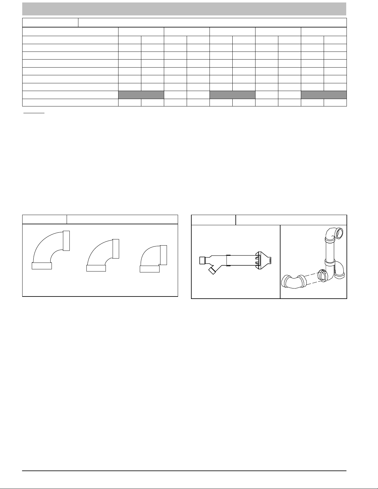
INSTALLATION INSTRUCTIONS Gas Furnace: (F/G)9MXT, (F/G)9MXE
Table 15 DEDUCTIONS FROM MAXIMUM EQUIVALENT VENT LENGTH - Feet (Meters)
Pipe Diameter (in): 11/2 2 21/2 3 4
Mitered 90º Elbow 8 (2.4) 8 (2.4) 8 (2.4) 8 (2.4) 8 (2.4)
Medium Radius 90º Elbow 5 (1.5) 5 (1.5) 5 (1.5) 5 (1.5) 5 (1.5)
Long Radius 90º Elbow 3 (0.9) 3 (0.9) 3 (0.9) 3 (0.9) 3 (0.9)
Mitered 45º Elbow 4 (1.2) 4 (1.2) 4 (1.2) 4 (1.2) 4 (1.2)
Medium Radius 45º Elbow 2.5 (0.8) 2.5 (0.8) 2.5 (0.8) 2.5 (0.8) 2.5 (0.8)
Long Radius 45º Elbow 1.5 (0.5) 1.5 (0.5) 1.5 (0.5) 1.5 (0.5) 1.5 (0.5)
Tee 16 (4.9) 16 (4.9) 16 (4.9) 16 (4.9) 16 (4.9)
Concentric Vent Termination NA 0 (0.0) NA 0 (0.0) NA
Standard Vent Termination 0 (0.0) 0 (0.0) 0 (0.0) 0 (0.0) 0 (0.0)
NOTES:
1. Use only the smallest diameter pipe possible for venting. Over−sizing may cause flame disturbance or excessive vent terminal
icing or freeze−up.
2. NA = Not allowed. Pressure switch will not close, or flame disturbance may result.
3. Not all furnace families include 26,000 or 140,000 BTUH input models.
4. Vent sizing for Canadian installation over 4500 ft. (1370 m) above sea level are subject to acceptance by local authorities having
jurisdiction.
5. Size both the combustion air and vent pipe independently, then use the larger size for both pipes.
6. Assume two 45° degree elbows equal one 90° degree elbow. Wide radius elbows are desirable and may be required in some
cases.
7. Elbow and pipe sections within the furnace casing and at the vent termination should not be included in vent length or elbow
count.
8. The minimum pipe length is 5 (1.5) linear feet (meters) for all applications.
9. Use 3−in (76 mm) diameter vent termination kit for installations requiring a 4−in (102 mm) diameter pipe.
Figure 67 Elbows Configurations
LONG
MEDIUM MITERED
L11F082
Figure 68 Vent Terminal Configurations
STANDARD 2−IN.,
3−IN. OR OPTIONAL
4−IN. TERMINATION
L11F083
A13110
62 440 01 4005 05
Specifications subject to change without notice.

INSTALLATION INSTRUCTIONS Gas Furnace: (F/G)9MXT, (F/G)9MXE
Venting System Length Calculations
The Total Equivalent Vent Length for EACH combustion air or vent pipe equals the length of the venting system, plus the equivalent
length of elbows used in the venting system from Table 15.
Standard vent terminations or factory accessory concentric vent terminations count for zero deduction.
See vent system manufacturer’s data for equivalent lengths of flexible vent pipe or other termination systems. DO NOT ASSUME
that one foot of flexible vent pipe equals one foot of straight PVC/ABS DWV vent pipe.
Compare the Total Equivalent Vent Length to the Maximum Equivalent Vent Lengths in Table 14.
Example 1
A direct-vent 60,000 BTUH furnace installed at 2100 ft. (640M). Venting system includes FOR EACH PIPE:
70 feet (22 M) of vent pipe, 65 feet (20 M) of combustion air inlet pipe, (3) 90º long-radius elbows, (2) 45º long-radius elbows, and a
factory accessory concentric vent kit.
Can this application use 2-in. (50 mm ND) PVC/ABS DWV vent piping?
Measure the required linear length of air inlet
and vent pipe; insert the longest of the two here
Add equiv length of (3) 90º long-radius elbows
(use the highest number of elbows for either the
vent or inlet pipe)
Add equiv length of (2) 45º long-radius elbows
(use the highest number of elbows for either the
vent or inlet pipe)
Add equiv length of factory concentric vent term 0 ft. From Table 15
Add correction for flexible vent pipe, if any 0 ft.
Total Equivalent Vent Length (TEVL)
3 x
2 x
3 ft
(0.9 M)
1.5 ft
(0.5 M)
70 ft.
(22 M)
9 ft.
=
(2.7 M)
3 ft.
=
(0.9 M)
82 ft.
(25 M)
Use length of the longer of the vent
or air inlet piping system
From Table 15
From Table 15
From Vent Manufacturer’s
instructions; zero for PVC/ABS DWV
Add all of the above lines
Maximum Equivalent Vent Length (MEVL)
Is TEVL less than MEVL? YES Therefore, 2” pipe MAY be used
95 ft.
(29 M)
For 2” pipe from Table 14
Example 2
A direct-vent 60,000 BTUH furnace installed at 2100 ft. (640M). Venting system includes FOR EACH PIPE:
50 feet (15 M) of vent pipe, 45 feet (14 M) of combustion air inlet pipe, (3) 90º long-radius elbows, and a polypropylene concentric
vent kit. Also includes 20 feet (6.1 M) of flexible polypropylene vent pipe, included within the 50 feet (15 M) of vent pipe.
VERIFY FROM POLYPROPYLENE VENT MANUFACTURER’S INSTRUCTIONS for the multiplier correction for flexible vent pipe.
Can this application use 60mm (o.d.) polypropylene vent piping? If not, what size piping can be used?
Measure the required linear length of RIGID air inlet and vent pipe;
insert the longest of the two here: 100 ft. Of rigid pipe − 20 ft. of flexible
pipe
Add equiv length of (3) 90º long-radius elbows
(use the highest number of elbows for either the
vent or inlet pipe)
Add equiv length of 45º long-radius elbows
(use the highest number of elbows for either the
vent or inlet pipe)
Add equiv length of concentric vent term 9 x
Add correction for flexible vent pipe, if any 2* x
* VERIFY FROM VENT MANUFACTURER’S INSTRUCTIONS; For example only, assume 1 meter of flexible 60mm (2”) or 80mm
(3”) polypropylene pipe equals 2 meters (6.5 ft.) of PVC/ABS pipe.
Total Equivalent Vent Length (TEVL)
Maximum Equivalent Vent Length (MEVL)
Is TEVL less than MEVL? NO
Maximum Equivalent Vent Length (MEVL)
Is TEVL less than MEVL? YES
3 x
0 x =
5 ft
(1.5 M)
3.3 ft
(0.9 M)
20 ft.
(6.1 M)
= 80 ft.
(24 M)
15 ft.
=
(4.6 M)
0 ft.
(0 M)
30 ft.
=
(9 M)
40 ft.
=
(12.2 M)
165 ft.
(50 M)
95 ft.
(29 M)
185 ft.
(57 M)
Use length of the longer of the vent
or air inlet piping system
Example from polypropylene vent
manufacturer’s instructions. Verify from
vent manufacturer’s instructions.
Add all of the above lines
For 2” pipe from Table 14
Therefore, 60mm (2”) pipe may NOT
be used; try 80mm (3”)
For 3” pipe from Table 14
Therefore, 80mm (3”) pipe MAY be
used
440 01 4005 05 63
Specifications subject to change without notice.

INSTALLATION INSTRUCTIONS Gas Furnace: (F/G)9MXT, (F/G)9MXE
Table 16 Maximum Allowable Exposed Vent Lengths Tables
Maximum Allowable Exposed Vent Length in Unconditioned Space (Feet)
Unit Size
Pipe Dia.
in.
Winter
Design
Temp
°F
Winter
Design
Temp
°F
Winter
Design
Temp
°F
Winter
Design
Temp
°F
* Not all families have these models
20
20
40
Unit Size
Pipe Dia.
in.
20
20
40
Unit Size 100,000 BTUH
Pipe Dia.
in.
20 20 50 40 35 20 80 95 80 20 80 105 90
20 15 10 5 20 35 30 20 20 45 35 25
40 10 5 20 25 20 10 20 30 25 15
Unit Size
Pipe Dia.
in.
20 10 50 40 10 75 95 10 75 105 5 55 50 5 65 105 5 65 125
-20 10 10 10 35 25 10 45 30 5 10 5 5 45 30 5 50 40
-40 10 5 10 25 15 10 30 20 5 5 5 30 20 5 35 25
Uninsulated 3/8-in. Insulation 1/2-in. Insulation
1½ 2 1½ 2 1½ 2 1 ½ 2 2 ½ 1 ½ 2 2 ½ 1 ½ 2 2 ½
20 20 50 45 60 50
0
0
0 20 20 15 10 20 55 45 35 20 65 55 45
0 10 20 15 10 55 45 10 65 50 5 25 15 5 65 50 5 65 60
5 5 25 20 30 25
Uninsulated 3/8in. Insulation 1/2in. Insulation
1 ½ 2 2 ½ 3 1 ½ 2 2 ½ 3 1 ½ 2 2 ½ 3 1 ½ 2 2 ½ 3 4 1 ½ 2 2 ½ 3 4 1 ½ 2 2 ½ 3 4
20 30 30 25 20 75 65 60 20 85 75 65
15 15 10 10 20 40 30 25 20 45 40 30
10 5 20 25 20 15 20 30 25 20
5 20 15 15 10 20 20 15 10
2 2 ½ 3 4 2 2 ½ 3 4 2 2 ½ 3 4
Uninsulated 3/8in. Insulation 1/2in. Insulation Uninsulated 3/8in. Insulation 1/2in. Insulation
2 ½ 3 4 2 ½ 3 4 2 ½ 3 4 2 ½ 3 4 2 ½ 3 4 2 ½ 3 4
Maximum Allowable Exposed Vent Length in Unconditioned Space (Metric)
Unit Size
Uninsulated 3/8-in. Insulation 1/2-in. Insulation Uninsulated
Pipe Dia.
mm
Winter
Design
Temp
°C
Winter
Design
Temp °C
Winter
Design
Temp
°C
Winter
Design
Temp
°C
* Not all families have these models
-7 6.1 6.1 15.2 13.7 18.3 15.2
-18 1.5 1.5 7.6 6.1 9.1 7.6
-29 4.6 3.0 6.1 4.6
-40 3.0 1.5 4.6 3.0
Unit Size 60,000 BTUH 80,000 BTUH
Pipe Dia.
mm
-7 6.1 9.1 9.1 7.6 6.1 22.9 19.8 18.3 6.1 25.9 22.9 19.8 4.6 12.2 12.2 10.7 9.1 4.6 15.2 27.4 22.9 19.8 4.6 15.2 21.3 21.3 21.3
-18 4.6 4.6 3.0 3.0 6.1 12.2 9.1 7.6 6.1 13.7 12.2 9.1 4.6 6.1 4.6 3.0 1.5 4.6 15.2 13.7 10.7 9.1 4.6 15.2 15.2 12.2 10.7
-29 3.0 1.5 6.1 7.6 6.1 4.6 6.1 9.1 7.6 6.1 4.6 3.0 1.5 4.6 10.7 9.1 6.1 4.6 4.6 12.2 9.1 7.6 4.6
-40 1.5 6.1 4.6 4.6 3.0 6.1 6.1 4.6 3.0 3.0 1.5 4.6 7.6 6.1 4.6 1.5 4.6 9.1 7.6 6.1 3.0
Unit Size 100,000 BTUH
Pipe Dia.
mm
-7 6.1 15.2 12.2 10.7 6.1 24.4 28.9 24.4 6.1 24.4 32.0 27.4
-18 6.1 6.1 4.6 3.0 6.1 16.8 13.7 10.7 6.1 19.8 16.7 13.7
-29 4.6 3.0 1.5 6.1 10.7 9.1 6.1 6.1 13.7 10.7 7.6
-40 3.0 1.5 6.1 7.6 6.1 3.0 6.1 9.1 7.6 4.6
Unit Size 120,000 BTUH 140,000* BTUH
Pipe Dia.
mm
-7 3.0 15.2 12.2 3.0 22.9 28.9 3.0 22.9 32.0 1.5 16.7 15.2 1.5 19.8 32.0 1.5 19.8 38.1
-18 3.0 6.1 4.6 3.0 16.8 13.7 3.0 19.8 15.2 1.5 7.6 4.6 1.5 19.8 15.2 1.5 19.8 18.3
-29 3.0 3.0 3.0 10.7 7.6 3.0 13.7 9.1 1.5 3.0 1.5 1.5 13.7 9.1 1.5 15.2 12.2
40 3.0 1.5 3.0 7.6 4.6 3.0 9.1 6.1 1.5 1.5 1.5 9.1 6.1 1.5 35 7.6
38 51 38 51 38 51 38 51 64 38 51 64 38 51 64
Uninsulated 3/8in. Insulation 1/2in. Insulation Uninsulated 3/8in. Insulation 1/2in. Insulation
38 51 64 76 38 51 64 76 38 51 64 76 38 51 64 76 102 38 51 64 76 102 38 51 64 76 102
51 64 76 102 51 64 76 102 51 64 76 102
Uninsulated 3/8in. Insulation 1/2in. Insulation Uninsulated 3/8in. Insulation 1/2in. Insulation
64 76 102 64 76 102 64 76 102 64 76 102 64 76 102 64 76 102
26,000* BTUH
15 10 20 15
10 5 15 10
60,000 BTUH
Uninsulated 3/8in. Insulation 1/2in. Insulation
120,000 BTUH 140,000* BTUH
26,000* BTUH
Uninsulated 3/8in. Insulation 1/2in. Insulation
Uninsulated 3/8in. Insulation 1/2in. Insulation
20 20 20 20 50 45 20 60 50
10 5 5 20 25 20 20 30 25
5 20 15 10 20 20 15
15 10 5 15 15 10
Uninsulated 3/8in. Insulation 1/2in. Insulation
15 40 40 35 30 15 50 90 75 65 15 50 70 70 70
15 20 15 10 5 15 50 45 35 30 15 50 50 40 35
15 10 5 15 35 30 20 15 15 40 30 25 15
10 5 15 25 20 15 5 15 30 25 20 10
6.1 6.1 6.1 6.1 15.2 13.7 6.1 18.3 15.2
3.0 1.5 1.5 6.1 7.6 6.1 6.1 9.1 7.6
1.5 6.1 4.6 3.0 6.1 6.1 4.6
40,000* BTUH
80,000 BTUH
40,000* BTUH
3/8in. Insulation 1/2in. Insulation
4.6 3.0 1.5 4.6 4.6 3.0
Copyright 2018 International Comfort Products
Lewisburg, TN 37091 USA
64 440 01 4005 05
Specifications subject to change without notice.
 Loading...