

ICP F9MXE0801716A1, F9MXE0401410A1, F9MXE0601714A1, (F/G)9MVT, (F/G)9MXT Installation Instructions Manual
...Page 1
HJJ(J|)i(i)))_J))1))
These instructions must be read and understood completely before attempting installation.
Safety Labeling and Signal Words
DANGER, WARNING, CAUTION, and NOTE
The signal words DANGER, WARNING,
CAUTION, and NOTE are used to identify levels of
hazard seriousness. The signal word DANGER is
only used on product labels to signify an immediate
hazard. The signal words WARNING, CAUTION,
and NOTE will be used on product labels and
throughout this manual and other manual that may
apply to the product.
DANGER - Immediate hazards which will result in
severe personal injury or death.
WARNING - Hazards or unsafe practices which
could result in severe personal injury or death.
CAUTION - Hazards or unsafe practices which
may result in minor personal injury or product or
property damage.
NOTE - Used to highlight suggestions which will
result in enhanced installation, reliability, or
operation.
TABLE OF CONTENTS
SAFETY CONSiDERATiONS ....................................... 3
iNTRODUCTiON ............................................... 4
CODES AND STANDARDS ........................................ 4
ELECTROSTATIC DISCHARGE (ESD) PRECAUTIONS PROCEDURE ........... 5
DIMENSIONS ................................................. 6
LOCATION ................................................... 7
LOCATION RELATIVE TO COOLING EQUIPMENT ........................ 9
AiR FOR COMBUSTION AND VENTiLATiON ............................ 9
CONDENSATE TRAP ............................................ 12
iNSTALLATION ................................................ 18
UPFLOW INSTALLATION ......................................... 18
DOWNFLOW INSTALLATION ....................................... 19
HORIZONTAL INSTALLATION ...................................... 22
FILTER ARRANGEMENT ......................................... 24
AiR DUCTS ................................................... 26
GAS PiPiNG .................................................. 26
ELECTRICAL CONNECTIONS ...................................... 28
J-BOX iNSTALLATION ........................................... 29
VENTING .................................................... 35
SPECIAL VENTING REQUIREMENTS FOR INSTALLATIONS iN CANADA ........ 35
DIRECT VENT / 2-PIPE SYSTEM ................................... 41
VENTILATED COMBUSTION AiR .................................... 41
TERMINATION REQUIREMENTS FOR THE
PROVINCES OF ALBERTA AND SASKATCHEWAN ....................... 41
iNSTALLING THE VENT TERMINATION ............................... 46
MAXIMUM EQUIVALENT VENT LENTH ............................... 50
Signal Words in Manuals
The signal word WARNING is used throughout
this manual in the following manner:
The signal word CAUTION is used throughout
this manual in the following manner:
Signal Words on Product Labeling
Signal words are used in combination with
colors and/or pictures or product labels.
Z_ Safety-alert symbol
When you see this symbol on the unit and in
instructions or manuals, be alert to the
potential for personal injury.
MAXIMUM ALLOWABLE EXPOSED VENT LENGTHS iN
UNCONDITIONED SPACE - SINGLE STAGE .......................... 51
MAXIMUM ALLOWABLE EXPOSED VENT LENGTHS iN
UNCONDITIONED SPACE - TWO-STAGE ............................ 52
IS09001)
Use of the AHRI Certified TM Mark indicates a
manufacturer's participation in the program,
For verification of certification for individual
products, go to www,ahridirectory.org .
INSTALLER: Affix these instructions on or adjacent to the
furnace,
CONSUMER: Retain these instructions for future
reference.
Portions of the text and tables are reprinted from NFPA 54/ANSI Z223.1-2009_;P, with permission of National Fire Protection Association, Quincy, MA 02269 and American Gas Association, Washington, DC
20001. This reprinted material is not the complete and official position of the NFPA or ANSI, on the referenced subject, which is represented only by the standard in its entirety,
PrintedinU.S.A. 440 01 4001 02 Sept.2011
Page 2
Required Notice for Massachusetts Installations
Important
The Commonwealth of Massachusetts requires compliance with regulation 248 CMR as follows:
5.08: Modifications to NFPA-54, Chapter 10
2) Revise 10.8.3 by adding the following additional requirements:
(a)
For all side wall horizontally vented gas fueled equipment installed in every dwelling, building or structure used in whole or in part for residential
purposes, including those owned or operated by the Commonwealth and where the side wall exhaust vent termination is less than seven (7) feet
above finished grade in the area of the venting, including but not limited to decks and porches, the following requirements shall be satisfied:
1,
INSTALLATION OF CARBON MONOXIDE DETECTORS. At the time of installation of the side wall horizontal vented gas fueled equipment, the
installing plumber or gasfitter shall observe that a hard wired carbon monoxide detector with an alarm and battery back-up is installed on the floor
level where the gas equipment is to be installed, in addition, the installing plumber or gasfitter shall observe that a battery operated or hard wired
carbon monoxide detector with an alarm is installed on each additional level of the dwelling, building or structure served by the side wall
horizontal vented gas fueled equipment. It shall be the responsibility of the property owner to secure the services of qualified license professionals
for the installation of hard wired carbon monoxide detectors.
a. In the event that the side wall horizontally vented gas fueled equipment is installed in a crawl space or an attic, the hard wired carbon
monoxide detector with alarm and battery back-up may be installed on the next adjacent floor level.
b. In the event that the requirements of this subdivision can not be met at the time of completion of installation, the owner shall have a period of
thirty (30) days to comply with the above requirement; provided, however, that during said thirty (30) day period, a battery operated carbon
monoxide detector with an alarm shall be installed.
2. APPROVED CARBON MONOXIDE DETECTORS. Each carbon monoxide detector as required in accordance with the above provisions shall
comply with NFPA 720 and be ANSI/UL 2034 listed and IAS certified.
3. SIGNAGE. A metal or plastic identification plate shall be permanently mounted to the exterior of the building at a minimum height of eight (8) feet
above grade directly in line with the exhaust vent terminal for the horizontally vented gas fueled heating appliance or equipment. The sign shall
read, in print size no less than one-half (1/2) inch in size, "GAS VENT DIRECTLY BELOW. KEEP CLEAR OF ALL OBSTRUCTIONS".
4. INSPECTION. The state of local gas inspector of the side wall horizontally vented gas fueled equipment shall not approve the installation unless,
upon inspection, the inspector observes carbon monoxide detectors and signage installed in accordance with the provisions of 248 CMR
5.08(2)(a) 1 through 4.
(b) EXEMPTIONS: The following equipment is exempt from 248 CMR 5.08(2)(a) 1 through 4:
1. The equipment listed in Chapter 10 entitled "Equipment Not Required To Be Vented" in the most current edition of NFPA 54 as adopted by the
Board; and
2. Product Approved side wall horizontally vented gas fueled equipment installed in a room or structure separate from the dwelling, building or
structure used in whole or in part for residential purposes.
(c)
MANUFACTURER REQUIREMENTS - GAS EQUIPMENT VENTING SYSTEM PROVIDED. When the manufacturer of Product Approved side wall
horizontally vented gas equipment provides a venting system design or venting system components with the equipment, the instructions provided by
the manufacturer for installation of the equipment and the venting system shall include:
1. Detailed instructions for the installation of the venting system design or the venting system components; and
2. A complete parts list for the venting system design or venting system.
(d)
MANUFACTURER REQUIREMENTS - GAS EQUIPMENT VENTING SYSTEM NOT PROVIDED. When the manufacturer of a Product Approved side
wall horizontally vented gas fueled equipment does not provide the parts for venting the flue gases, but identifies "special venting systems", the
following requirements shall be satisfied by the manufacturer:
1. The referenced "special venting system" instructions shall be included with the appliance or equipment installation instructions; and
2. The "special venting systems" shall be Product Approved by the Board, and the instructions for that system shall include a parts list and detailed
installation instructions.
(e)
A copy of all installation instructions for all Product Approved side wall horizontally vented gas fueled equipment, all venting instructions, all parts lists
for venting instructions, and/or all venting design instructions shall remain with the appliance or equipment at the completion of the installation.
For questions regarding these requirements, please contact the Commonwealth of Massachusetts Board of State Examiners of Plumbers and Gas
Fitters, 239 Causeway Street, Boston, MA 02114. 617-727-9952
2 Specifications are subject to change without notice. 440 01 4001 02
Page 3
Safety Considerations
FIRE, EXPLOSION, ELECTRICAL SHOCK, AND
CARBON MONOXIDE POISONING HAZARD
Failure to follow this warning could result in dangerous
operation, personal injury, death, or property damage.
Improper installation, adjustment, alteration, service,
maintenance, or use can cause carbon monoxide
poisoning, explosion, fire, electrical shock, or other
conditions which may cause personal injury or property
damage. Consult a qualified service agency, local gas
supplier, or your distributor or branch for information or
assistance. The qualified service agency must use
only factory-authorized and listed kits or accessories
when modifying this product.
FURNACE RELIABILITY HAZARD
Failure to follow this caution may result in unit
component damage.
Application of this furnace should be indoors with
special attention given to vent sizing and material, gas
input rate, air temperature rise, unit leveling, and unit
sizing.
Improper installation, adjustment, alteration, service,
maintenance, or use can cause explosion, fire, electrical shock,
or other conditions which may cause personal injury or property
damage. Consult a qualified service agency, local gas supplier,
or your distributor or branch for information or assistance. The
qualified installer or agency must use only factory-authorized
and listed kits or accessories when modifying this product.
Refer to the individual instructions packaged with the kits or
accessories when installing.
Installing and servicing heating equipment can be hazardous
due to gas and electrical components. Only trained and
qualified personnel should install, repair, or service
heating equipment. Untrained personnel can perform basic
maintenance functions such as cleaning and replacing air
filters. All other operations must be performed by trained
service personnel. When working on heating equipment,
observe precautions in literature, on tags, and on labels
attached to or shipped with furnace and other safety
precautions that may apply.
These instructions cover minimum requirements and conform
to existing national standards and safety codes. In some
instances, these instructions exceed certain local codes and
ordinances, especially those that may not have kept up with
changing residential construction practices. We require these
instructions as a minimum for a safe installation.
Follow all safety codes. Wear safety glasses, protective
clothing, and work gloves. Have a fire extinguisher available.
Read these instructions thoroughly and follow all warnings or
cautions included in literature and attached to the unit.
CUT HAZARD
Failure to follow this caution may result in personal
injury.
Sheet metal parts may have sharp edges or burrs. Use
care and wear appropriate protective clothing, safety
glasses and gloves when handling parts, and servicing
furnaces.
This is the safety-alert symbol /N •When you see this symbol
on the furnace and in instructions or manuals, be alert to the
potential for personal injury.
Understand the signal words DANGER, WARNING, and
CAUTION. These words are used with the safety-alert symbol.
DANGER identifies the most serious hazards which will result
in severe personal injury or death. WARNING signifies a
hazard which could result in personal injury or death.
CAUTION is used to identify hazards which may result in minor
personal injury or product and property damage. NOTE is used
to highlight suggestions which will result in enhanced
installation, reliability, or operation.
1. Use only with type of gas approved for this furnace.
Refer to the furnace rating plate.
2. Install this furnace only in a location and position as
specified in the "Location" section of these instructions.
3. Provide adequate combustion and ventilation air to the
furnace space as specified in "Air for Combustion and
Ventilation" section.
4. Combustion products must be discharged outdoors.
Connect this furnace to an approved vent system only,
as specified in the "Venting" section of these
instructions.
5. Never test for gas leaks with an open flame. Use a
commercially available soap solution made specifically
for the detection of leaks to check all connections, as
specified in the "Gas Piping" section.
6. Always install furnace to operate within the furnace's
intended temperature-rise range with a duct system
which has an external static pressure within the
allowable range, as specified in the "Start-Up,
Adjustments, and Safety Check" section. See furnace
rating plate.
7. When a furnace is installed so that supply ducts carry air
circulated by the furnace to areas outside the space
containing the furnace, the return air shall also be
handled by duct(s) sealed to the furnace casing and
terminating outside the space containing the furnace.
See "Air Ducts" section.
8. A gas-fired furnace for installation in a residential
garage must be installed as specified in the warning box
in the "Location" section. (See Figure 4)
9. The furnace may be used for construction heat provided
that the furnace installation and operation complies with
the first CAUTION in the LOCATION section on page 7
of these instructions.
10. These Multipoise Gas-Fired Furnaces are CSA
design-certified for use with natural and propane gases
(see furnace rating plate) and for installation in alcoves,
attics, basements, closets, utility rooms, crawlspaces,
and garages. The furnace is factory-shipped for use
with natural gas. A CSA (A.G.A. and C.G.A.) listed
accessory gas conversion kit is required to convert
furnace for use with propane gas.
11. See Table 1 for required clearances to combustible
construction.
440 01 4001 02 Specificati ..... bject to change without notice. 3
Page 4
12.
Maintain a 1-in. (25 mm) clearance from combustible
materials to supply air ductwork for a distance of 36-in.
(914 mm) horizontally from the furnace. See NFPA 90B
or local code for further requirements.
Minimum Clearances to
Table 1 Combustible Materials for All Units
POSITION
CLEARANCE
In(mm)
REAR 0
FRONT (Combustion air openings in
furnace and in structure) 1 (25)
Required for service 24 (610)
All Sides of Supply Plenum 1 (25)
Sides 0
Vent 0
Top of Furnace 1 (25)
13. These furnaces SHALL NOT be installed directly on
carpeting, tile, or any other combustible material other
than wood flooring. In downflow installations, factory
accessory floor base MUST be used when installed on
combustible materials and wood flooring. Special base
is not required when this furnace is installed on
manufacturer's CoilAssemblyorwhen Coil Box is used.
See Table 1 for clearance to combustible construction
information.
Introduction
The 4-way multipoise Category IV condensing furnace is CSA
design-certified as a direct (2-pipe) or non-direct vent (1-pipe)
furnace. (See Figure 3) The furnace is factory-shipped for use
with natural gas. The furnace can be converted in the field for
use with propane gas when a factory-supplied conversion kit is
used. Refer to the furnace rating plate for conversion kit
information.
Single Stage furnace is approved for installation in a mobile
home when a factory-supplied accessory mobile home
conversion kit is used. The conversion kit is required for use
with both natural and propane gas. The furnace must also be
installed on a factory-supplied accessory combustible floor
base or evaporator coil casing.
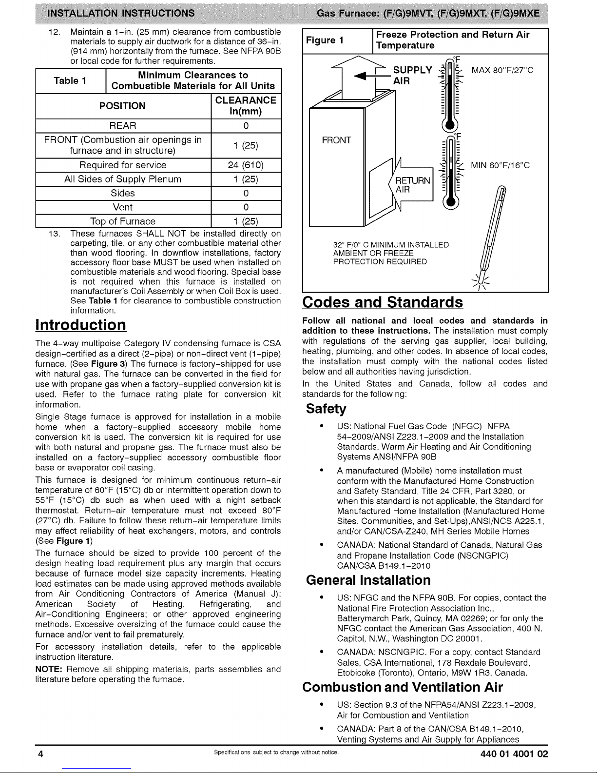
This furnace is designed for minimum continuous return-air
temperature of 60°F (15°C) db or intermittent operation down to
55°F (15°C) db such as when used with a night setback
thermostat. Return-air temperature must not exceed 80°F
(27°C) db. Failure to follow these return-air temperature limits
may affect reliability of heat exchangers, motors, and controls
(See Figure 1)
The furnace should be sized to provide 100 percent of the
design heating load requirement plus any margin that occurs
because of furnace model size capacity increments. Heating
load estimates can be made using approved methods available
from Air Conditioning Contractors of America (Manual J);
American Society of Heating, Refrigerating, and
Air-Conditioning Engineers; or other approved engineering
methods. Excessive oversizing of the furnace could cause the
furnace and/or vent to fail prematurely.
For accessory installation details, refer to the applicable
instruction literature.
NOTE: Remove all shipping materials, parts assemblies and
literature before operating the furnace.
Figure 1
I Freeze Protection and Return Air
Temperature
SUPPLY MAX80°F/27°C
_AIR
FRONT
MIN 60°F/16°C
32° F/0° C MINIMUM INSTALLED
AMBIENT OR FREEZE
PROTECTION REQUIRED
J
Codes and Standards
Follow all national and local codes and standards in
addition to these instructions. The installation must comply
with regulations of the serving gas supplier, local building,
heating, plumbing, and other codes. In absence of local codes,
the installation must comply with the national codes listed
below and all authorities having jurisdiction.
In the United States and Canada, follow all codes and
standards for the following:
Safety
• US: National Fuel Gas Code (NFGC) NFPA
54-2009/ANSI Z223.1-2009 and the Installation
Standards, Warm Air Heating and Air Conditioning
Systems ANSI/NFPA 90B
• A manufactured (Mobile) home installation must
conform with the Manufactured Home Construction
and Safety Standard, Title 24 CFR, Part 3280, or
when this standard is not applicable, the Standard for
Manufactured Home Installation (Manufactured Home
Sites, Communities, and Set-Ups),ANSI/NCS A225.1,
and/or CAN/CSA-Z240, MH Series Mobile Homes
• CANADA: National Standard of Canada, Natural Gas
and Propane Installation Code (NSCNGPIC)
CAN/CSA B149.1-2010
General Installation
• US: NFGC and the NFPA 90B. For copies, contact the
National Fire Protection Association Inc.,
Batterymarch Park, Quincy, MA 02269; or for only the
NFGC contact the American Gas Association, 400 N.
Capitol, N.W., Washington DC 20001.
• CANADA: NSCNGPIC. For a copy, contact Standard
Sales, CSA International, 178 Rexdale Boulevard,
Etobicoke (Toronto), Ontario, M9W 1R3, Canada.
Combustion and Ventilation Air
• US: Section 9.3 ofthe NFPA54/ANSI Z223.1-2009,
Air for Combustion and Ventilation
• CANADA: Part 8 of the CAN/CSA B149.1-2010,
Venting Systems and Air Supply for Appliances
Specificati ..... bject to change without notice. 440 01 4001 02
Page 5
Duct Systems
• US and CANADA: Air Conditioning Contractors
Association (ACCA) Manual D, Sheet Metal and Air
Conditioning Contractors National Association
(SMACNA), or American Society of Heating,
Refrigeration, and Air Conditioning Engineers (ASHRAE)
2005 Fundamentals Handbook Chapter 35.
Acoustical Lining and Fibrous Glass
Duct
• US and CANADA: current edition of SMACNA, NFPA
90B as tested by UL Standard 181 for Class I Rigid Air
Ducts
Gas Piping and Gas Pipe Pressure
Testing
• U.S.A.: NFPA 54/ANSI Z223.1-2009, NFGC; Chapters
5, 6, 7, and 8 and national plumbing codes.
• CANADA: CAN/CSA-B149.1-2010, Parts 4, 5, 6 and
9.
In the state of Massachusetts:
• This product must be installed by a licensed plumber or
gas fitter.
• When flexible connectors are used, the maximum
length shall not exceed 36-in. (914 mm).
• When lever type gas shutoffs are used they shall be
T-handle type.
• The use of copper tubing for gas piping is not
approved by the state of Massachusetts.
Electrical Connections
• U.S.A.: National Electrical Code (NEC) ANSI/NFPA
70-2011
• CANADA: Canadian Electrical Code CSA C22.1
Electrostatic Discharge (ESD)
Precautions Procedure
FURNACE RELIABILITY HAZARD
Failure to follow this caution may result in unit com-
3onent damage.
Electrostatic discharge can affect electronic compon-
ents. Take precautions during furnace installation and
servicing to protect the furnace electronic control. Pre-
cautions will prevent electrostatic discharges from per-
sonnel and hand tools which are held during the pro-
cedure. These precautions will help to avoid exposing
the control to electrostatic discharge by putting the
furnace, the control, and the person at the same elec-
trostatic potential.
1. Disconnect all power to the furnace. Multiple
disconnects may be required. DO NOT TOUCH THE
CONTROL OR ANY WIRE CONNECTED TO THE
CONTROL PRIOR TO DISCHARGING YOUR BODY'S
ELECTROSTATIC CHARGE TO GROUND.
2. Firmly touch the clean, unpainted, metal surface of the
furnace chassis which is close to the control. Tools held
in a person's hand during grounding will be satisfactorily
discharged.
3. After touching the chassis, you may proceed to service
the control or connecting wires as long as you do nothing
to recharge your body with static electricity (for example;
DO NOT move or shuffle your feet, do not touch
ungrounded objects, etc.).
4. If you touch ungrounded objects (and recharge your
body with static electricity), firmly touch a clean,
unpainted metal surface of the furnace again before
touching control or wires.
5. Use this procedure for installed and uninstatled
(ungrounded) furnaces.
6. Before removing a new control from its container,
discharge your body's electrostatic charge to ground to
protect the control from damage. If the control is to be
installed in a furnace, follow items 1 through 4 before
bringing the control or yourself in contact with the
furnace. Put all used and new controls into containers
before touching ungrounded objects.
7. An ESD service kit (available from commercial sources)
may also be used to prevent ESD damage.
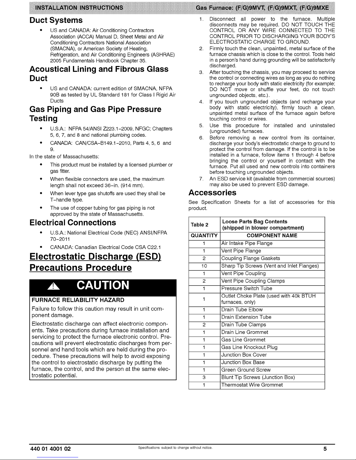
Accessories
See Specification Sheets for a list of accessories for this
product.
Table 2
QUANTITY COMPONENT NAME
1 Air Intake Pipe Flange
1 Vent Pipe Flange
2 Coupling Flange Gaskets
10 Sharp Tip Screws (Vent and Inlet Flanges)
1 Vent Pipe Coupling
2 Vent Pipe Coupling Clamps
1 Pressure Switch Tube
1
1 Drain Tube Elbow
1 Drain Extension Tube
2 Drain Tube Clamps
1 Drain Line Grommet
1 Gas Line Grommet
1 Gas Line Knockout Plug
1 Junction Box Cover
1 Junction Box Base
1 Green Ground Screw
3 Blunt Tip Screws (Junction Box)
1 Thermostat Wire Grommet
Loose Parts Bag Contents
(shipped in blower compartment)
Outlet Choke Plate (used with 40k BTUH
furnaces, only)
440 01 4001 02 Specificati ..... bject to change without notice. 5
Page 6
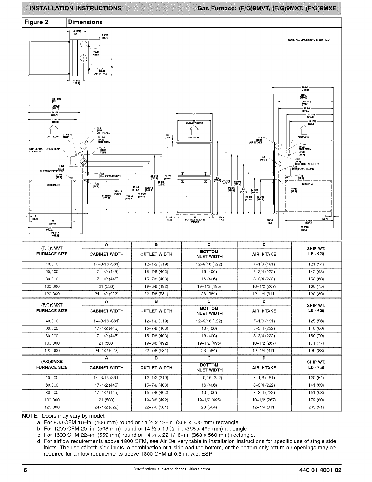
Figure 2
LOCATION
JDimensions
615/1(
[17&1] 23/10
611116
[17o41
NOlle; ALL DIMENSIONS IN INCH [MM]
OUTLET WIDTH
AIR FLOW
[22.2]POWERCONN
(F/G)9MVT
FURNACE SIZE
40,000
60,000
80,000
100,000
120,000
(F/G)9MXT
FURNACE SIZE
40,000
60,000
80,000
100,000
120,000
(F/G)9MXE
FURNACE SIZE
40,000 14-3/16 (361) 12-1/2 (319) 7-1/8 (181)
60,000 17-1/2 (445) 15-7/8 (403) 8-3/4 (222)
80,000 17-1/2 (445) 15-7/8 (403) 8-3/4 (222)
100,000 21 (533) 19-3/8 (492) 10-1/2 (267)
120,000 24-1/2 (622) 22-7/8 (581) 12-1/4 (311)
A
CABINET WIDTH
14-3/16 (361)
17-1/2 (445)
17-1/2 (445)
21 (533)
24-1/2 (622)
A
CABINET WIDTH
14-3/16 (361)
17-1/2 (445)
17-1/2 (445)
21 (533)
24-1/2 (622)
A
CABINET WIDTH
B
OUTLET WIDTH
12-1/2 (319)
15-7/8 (403)
15-7/8 (403)
19-3/8 (492)
22-7/8 (581)
B
OUTLET WIDTH
12-1/2 (319)
15-7/8 (403)
15-7/8 (403)
19-3/8 (492)
22-7/8 (581)
B
OUTLET WIDTH
C
BOTTOM
INLET WIDTH
12-9/16 (322)
16 (406)
16 (406)
19-1/2 (495)
23 (584)
C
BOTTOM
INLET WIDTH
12-9/16 (322)
16 (406)
16 (406)
19-1/2 (495)
23 (584)
C
BOTTOM
INLET WIDTH
12-9/16 (322)
16 (406)
16 (406)
19-1/2 (495)
23 (584)
D
AIR INTAKE
7-1/8 (181)
8-3/4 (222)
8-3/4 (222)
10-1/2 (267)
12-1/4 (311)
D
AIR INTAKE
7-1/8 (181)
8-3/4 (222)
8-3/4 (222)
10-1/2 (267)
12-1/4 (311)
D
AIR INTAKE
NOTE: Doors may vary by model.
a. For 800 CFM 16-in. (406 mm) round or 14 ½ x 12-in. (368 x 305 mm) rectangle.
b. For 1200 CFM 20-in. (508 mm) round of 14 ½ x 19 ½-in. (368 x 495 mm) rectangle.
c. For 1600 CFM 22-in. (559 mm) round or 14 ½ x 22 1/16-in. (368 x 560 mm) rectangle.
d. For airflow requirements above 1800 CFM, see Air Delivery table in Installation Instructions for specific use of single side
inlets. The use of both side inlets, a combination of 1 side and the bottom, or the bottom only return air openings may be
required for airflow requirements above 1800 CFM at 0.5 in. w.c. ESP
SHIP WT,
LB (KG)
121 (54)
142 (63)
152 (68)
166 (75)
190 (86)
SHIP WT,
LB (KG)
125 (56)
146 (66)
156 (70)
171 (77)
195 (88)
SHIP WT,
LB (KG)
120 (54)
141 (63)
151 (68)
179 (80)
203 (91)
6 Specificati ..... bject to change without notice. 440 01 4001 02
Page 7
Location
PERSONAL INJURY AND/OR PROPERTY DAMAGE
HAZARD
Improper use or installation of this furnace may result in
3remature furnace component failure. This gas furnace
may be used for heating buildings under construction
3rovided that:
-The furnace is permanently installed with all electrical
wiring, piping, venting and ducting installed according to
these installation instructions. A return air duct is
3rovided, sealed to the furnace casing, and terminated
outside the space containing the furnace. This prevents
a negative pressure condition as created by the
circulating air blower, causing a flame rollout and/or
drawing combustion products into the structure.
-The furnace is controlled by a thermostat. It may not be
"hot wired" to provide heat continuously to the structure
without thermostatic control.
-Clean outside air is provided for combustion. This is to
minimize the corrosive effects of adhesives, sealers and
other construction materials. It also prevents the
entrainment of drywall dust into combustion air, which
can cause fouling and plugging of furnace components.
-The temperature of the return air to the furnace is
maintained between 55°F (13°C) and 80°F (27°C), with
no evening setback or shutdown. The use of the furnace
while the structure is under construction is deemed to be
intermittent operation per our installation instructions.
-The air temperature rise is within the rated rise range on
the furnace rating plate, and the gas input rate has been
set to the nameplate value.
-The filters used to clean the circulating air during the
construction process must be either changed or
thoroughly cleaned prior to occupancy.
-The furnace, ductwork and filters are cleaned as
necessary to remove drywall dust and construction
debris from all HVAC system components after
construction is completed.
-Verify proper furnace operating conditions including
ignition, gas input rate, air temperature rise, and venting
according to these installation instructions.
General
These furnaces are shipped with the following materials to
assist in proper furnace installation. These materials are
shipped in the main blower compartment.
See Table 2 for loose parts bog contents.
This furnace must:
• be installed so the electrical components are protected
from water.
• notbe installeddirectlyon any combustiblematerial other
than wood flooring (refer to SAFETY
CONSIDERATIONS).
be located close to the chimney or vent and attached to an
air distribution system. Refer to Air Ducts section.
be provided ample space for servicing and cleaning.
Always comply with minimum fire protection clearances
shown in Table 1 or on the furnace clearance to
combustible construction label.
CARBON MONOXIDE POISONING / COMPONENT
DAMAGE HAZARD
Failure to follow this warning could result in personal in-
jury or death and unit component damage.
Corrosive or contaminated air may cause failure of parts
containing flue gas, which could leak into the living
space. Air for combustion must not be contaminated by
halogen compounds, which include fluoride, chloride,
bromide, and iodide. These elements can corrode heat
exchangers and shorten furnace life. Air contaminants
are found in aerosol sprays, detergents, bleaches, clean-
ing solvents, salts, air fresheners, and other household
products. Do not install furnace in a corrosive or contam-
inated atmosphere. Make sure all combustion and circu-
lating air requirements are met, in addition to all local
codes and ordinances.
The following types of furnace installations may require
OUTDOOR AIR for combustion due to chemical exposures:
• Commercial buildings
• Buildings with indoor pools
• Laundry rooms
• Hobby or craft rooms, and
• Chemical storage areas
If air is exposed to the following substances, it should not be
used for combustion air, and outdoor air may be required for
combustion:
• Permanent wave solutions
• Chlorinated waxes and cleaners
• Chlorine based swimming pool chemicals
• Water softening chemicals
• De-icing salts or chemicals
• Carbon tetrachloride
• Halogen type refrigerants
• Cleaning solvents (such as perchloroethylene)
• Printing inks, paint removers, varnishes, etc.
• Hydrochloric acid
• Cements and glues
• Antistatic fabric softeners for clothes dryers
• Masonry acid washing materials
All fuel-burning equipment must be supplied with air for fuel
combustion. Sufficient air must be provided to avoid negative
pressure in the equipment room or space. A positive seal must
be made between the furnace cabinet and the return-air duct
to prevent pulling air from the burner area.
440 01 4001 02 Specificati ..... bject to change without notice. 7
Page 8

Figure 3 1Multipoise Orientations
THE BLOWER iS LOCATED
TOTHE RIGHT OFTHE
BURNER SECTION, AND
AIR CONDiTiONED AiR iS
DISCHARGED TO THE LEFT.
AIRFLOW
THE BLOWER iS
LOCATED BELOW THE
BURNER SECTION, AND
CONDiTiONED AIR iS
DISCHARGED UPWARD.
I HORIZONTAL RIGHT/AIFF_LQW
THE BLOWER iS
LOCATED ABOVE THE
BURNER SECTION, AND
CONDiTiONED AiR iS
DISCHARGED DOWNWARD AIRFLOW
FIRE, INJURY OR DEATH HAZARD
Failure to follow this warning could result in personal in-
jury, death and/or property damage.
When the furnace is installed in a residential garage, the
burners and ignition sources must be located at least
18-in. (457 mm) above the floor. The furnace must be
located or protected to avoid damage by vehicles. When
the furnace is installed in a public garage, airplane
hangar, or other building having a hazardous atmo-
sphere, the furnace must be installed in accordance with
the NFPA 54/ANSI Z223.1-2009 or CAN/CSA
B149.1-2010. (See Figure 4)
Figure 4 1Installation in a Garage
THE BLOWER iS
LOCATED TO THE LEFT
OF THE BURNER SECTION,
AND CONDiTiONED AiR iS
DISCHARGED TO THE RIGHT.
FIRE HAZARD
Failure to follow this warning could result in personal in-
jury, death and/or property damage.
Do not install the furnace on its back or hang furnace with
control compartment facing downward. Safety control
operation will be adversely affected. Never connect re-
turn-air ducts to the back of the furnace. (See Figure 5)
Figure 5 _Prohibit Installations
BACK
18-1N. (457.2 mm)
MINIMUM TO BURNERS
8 Specificati ..... bject to change without notice. 440 01 4001 02
A10494
A93044
Page 9
Location Relative to Cooling
Equipment
The cooling coil must be installed parallel with, or on the
downstream side of the unit to avoid condensation in the heat
exchangers. When installed parallel with the furnace, dampers
or other flow control must prevent chilled air from entering the
furnace. If the dampers are manually operated, they must be
equipped with means to prevent operation of either unit unless
the damper is in the full-heat or full-cool position.
Air for Combustion and
Ventilation
Introduction
FURNACE CORROSION HAZARD
Failure to follow this caution may result in furnace
damage.
Air for combustion must not be contaminated by halogen
compounds, which include fluoride, chloride, bromide,
and iodide. These elements can corrode heat
exchangers and shorten furnace life. Air contaminants
are found in aerosol sprays, detergents, bleaches,
cleaning solvents, salts, air fresheners, and other
household products.
Direct Vent (2-pipe) Applications
When the furnace is installed as a direct vent (2-pipe) furnace,
no special provisions for air for combustion are required.
However, other gas appliances installed in the space with the
furnace may require outside air for combustion. Follow the
guidelines below to insure that other gas appliances have
sufficient air for combustion.
Non-Direct Vent (1-pipe) Applications
When the furnace is installed as a non-direct vent (1-pipe)
furnace, it wilt be necessary to insure there is adequate air for
combustion. Other gas appliances installed with the furnace
may also require air for combustion and ventilation in addition
to the amount of combustion air and ventilation air required for
the furnace. Follow the guidelines below to insure that the
furnace and other gas appliances have sufficient air for
combustion.
Ventilated Combustion Air Applications
When the furnace is installed using the ventilated combustion
air option, the attic or crawlspace must freely communicate with
the outdoor to provide sufficient air for combustion. The
combustion air pipe cannot be terminated in attics or
crawlspaces that use ventilation fans designed to operate
during the heating season. If ventilation fans are present in
these areas, the combustion air pipe must terminate outdoors
as a Direct Vent/2-Pipe system.
All air for combustion is piped directly to the furnace from a
space that is well ventilated with outdoor air (such as an attic or
crawlspace) and the space is well isolated from the living space
or garage. In addition, other gas appliances installed in the
space with the furnace may require outside air for combustion.
Follow the guidelines below to insure that the roof or
crawlspace walls have sufficient free area to provide sufficient
air for combustion and ventilation for the furnaces. The
guidelines below can be used to insure that other gas
appliances have sufficient air for combustion.
Provisions for adequate combustion, ventilation, and dilution air
must be provided in accordance with:
• U.S. Installations: Section 9.3 of the NFPA 54/ANSI
Z223.1-2009 , Air for Combustion and Ventilation and
applicable provisions of the local building codes.
• Canadian Installations: Part 8 of
CAN/CSA-B149.1-2010, Venting Systems and Air
Supply for Appliances and all authorities having
jurisdiction.
440 01 4001 02 Specificati ..... bject to change without notice. 9
CARBON MONOXIDE POISONING HAZARD
Failure to follow this warning could result in personal
injury or death.
The operation of exhaust fans, kitchen ventilation fans,
clothes dryers, attic exhaust fans or fireplaces could
create a NEGATIVE PRESSURE CONDITION at the
furnace. Make-up air MUST be provided for the
ventilation devices, in addition to that required by the
furnace. Refer to the Carbon Monoxide Poisoning
Hazard warning in the venting section of these
instructions to determine if an adequate amount of
make-up air is available.
The requirements for combustion and ventilation air depend
upon whether or not the furnace is located in a space having a
volume of at least 50 cubic feet per 1,000 Btuh (4.8 cubic
meters per kW) input rating for all gas appliances installed in
the space.
• Spaces having less than 50 cubic feet per 1,000 Btuh (4.8
cubic meters per kW) require the OUTDOOR
COMBUSTION AIR METHOD.
• Spaces having at least 50 cubic feet per 1,000 Btuh (4.8
cubic meters per kW) may use the INDOOR
COMBUSTION AIR, STANDARD or KNOWN AIR
INFILTRATION METHOD.
Outdoor Combustion Air Method
1. Provide the space with sufficient air for proper
combustion, ventilation, and dilution of flue gases using
permanent horizontal or vertical duct(s) or opening(s)
directly communicating with the outdoors or spaces that
freely communicate with the outdoors.
2. Figure 6 illustrates how to provide TWO OUTDOOR
OPENINGS, one inlet and one outlet combustion and
ventilation air openings to the outdoors.
a. One opening MUST commence within 12-in.
(300 mm) of the ceiling and the second opening
MUST commence within 12-in. (300 mm) of the floor.
b. Size openings and ducts per Figure 6 and Table 3.
c. TWO HORIZONTAL DUCTS require 1 square inch
(25.4 square mm) of free area per 2,000 Btuh (1,100
mm2/kW) of combined input for all gas appliances in
the space per Figure 6 and Table 3.
d. TWO OPENINGS OR VERTICAL DUCTS require 1
square inch (25.4 square mm)of free area per 4,000
Btuh (550 mm2/kW) for combined input of all gas
appliances in the space per Figure 6 and Table 3.
3. ONE OUTDOOR OPENING requires:
a. 1 sq. in. (25.4 square mm)of free area per 3,000 Btuh
(734 mm2/kW) for combined input of all gas
appliances in the space per Table 3 and
Page 10
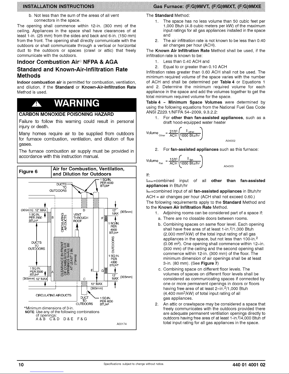
b. Not less than the sum of the areas of all vent
connectors in the space.
The opening shall commence within 12-in. (300 mm) of the
ceiling. Appliances in the space shall have clearances of at
least 1-in. (25 mm) from the sides and back and 6-in. (150 mm)
from the front. The opening shall directly communicate with the
outdoors or shall communicate through a vertical or horizontal
duct to the outdoors or spaces (crawl or attic) that freely
communicate with the outdoors.
Indoor Combustion Air ° NFPA & AGA
Standard and Known-Air-Infiltration Rate
Methods
Indoor combustion air is permitted for combustion, ventilation,
and dilution, if the Standard or Known-Air-Infiltration Rate
Method is used.
CARBON MONOXIDE POISONING HAZARD
Failure to follow this warning could result in personal
injury or death.
Many homes require air to be supplied from outdoors
for furnace combustion, ventilation, and dilution of flue
gases.
The furnace combustion air supply must be provided in
accordance with this instruction manual.
Figure 6
(305_m/12"M_X]j
lseiN, ill
PER 2000 B
BTUH*
sa i .
PER 2000 A
(305mm)12"MAN | I
CIRCULATINGAIR DUCTS
*Minimum dimensions of 3-in.
NOTE: Use any of the following combinations
of openings:
A&B C&D D&E F&G
Air for Combustion, Ventilation,and Dilution for Outdoors
DUCTS ,
TO BTUH
OUiDOORS
I I Ii
D
VENT
THROUGH
ROOF
I
' 1
TO PER 4000
OUTDOORS BTUH*
12" MAX
(305mm)
1 SQ IN.
I SQ IN,
/
f
12/_X (305ram}
t
1 so IN.
PER
4000
BTUH*
09
n-
O
O
£
o
SQ IN,
PER
4000
BTUH*
_2j_X (aO5mm)
t
A03174
The Standard Method:
1. The space has no less volume than 50 cubic feet per
1,000 Btuh (4.8 cubic meters per kW) of the maximum
input ratings for all gas appliances installed inthe space
and
2. The air infiltration rate is not known to be less than 0.40
air changes per hour (ACH).
The Known Air Infiltration Rate Method shall be used, if the
infiltration rate is known to be:
1. Less than 0.40 ACH and
2. Equal to or greater than 0.10 ACH
Infiltration rates greater than 0.60 ACH shall not be used. The
minimum required volume of the space varies with the number
of ACH and shall be determined per Table 4 or Equations 1
and 2. Determine the minimum required volume for each
appliance in the space and add the volumes together to get the
total minimum required volume for the space.
Table 4 - Minimum Space Volumes were determined by
using the following equations from the National Fuel Gas Code
ANSI Z223.1/NFPA 54-2009, 9.3.2.2:
1. For other than fan-assisted appliances, such as a
draft hood-equipped water heater
Volume -21ft3 _f' I°ther
Other ACH _.000 Btu/hrJ
A04002
2. For fan-assisted appliances such as this furnace:
Volume Fan ACH 000 Btu/hr
A04003
If:
Iother=combined input of all other than fan-assisted
appliances in Btuh/hr
Itan=combined input of all fan-assisted appliances in Btuh/hr
ACH = air changes per hour (ACH shall not exceed 0.60.)
The following requirements apply to the Standard Method and
to the Known Air Infiltration Rate Method.
1. Adjoining rooms can be considered part of a space if:
a. There are no closable doors between rooms.
b. Combining spaces on same floor level. Each opening
shall have free area of at least 1-in.2/1,000 Btuh
(2,000 mm2/kW) of the total input rating of all gas
appliances in the space, but not less than 100-in. 2
(0.06 m2). One opening shall commence within 12-in.
(300 mm) of the ceiling and the second opening shall
commence within 12-in. (300 mm) of the floor. The
minimum dimension of air openings shall be at least
3-in. (80 mm). (See Figure 7)
c. Combining space on different floor levels. The
volumes of spaces on different floor levels shall be
considered as communicating spaces if connected by
one or more permanent openings in doors or floors
having free area of at least 2-in.2/1,000 Btuh
(4,400 mm2/kW) of total input rating of all
gas appliances.
2. An attic or crawlspace may be considered a space that
freely communicates with the outdoors provided there
are adequate permanent ventilation openings directly to
outdoors having free area of at least 1-in.2/4,000 Btuh of
total input rating for all gas appliances in the space.
10 Specificati ..... bject to change without notice. 440 01 4001 02
Page 11
Airfor Combustion,Ventilation, 3.
Figure 7 and Dilution from Indoors
In spaces that use the Indoor Combustion Air Method,
infiltration should be adequate to provide air for
combustion, permanent ventilation and dilution of flue
gases. However, in buildings with unusually tight
CIRCULATING AIR VENT THROUGH ROOF
DUCTS
I
I
I
I I I I
I I I I
I I I I
_(305mm)
construction, additional air MUST be provided using
the methods described in the Outdoor Combustion Air
Method section.
4.
Unusually tight construction is defined as Construction
with:
a.
Walls and ceilings exposed to the outdoors have a
continuous, sealed vapor barrier. Openings are
E_ ----_SQIN.
_" _ = PER 1000
_: _ BTUH* IN DOOR
_ ORWALL
INTERIOR
HEATED
SPACE
i C_ UNCONFINED
rr T 6" MIN (152ram)
u_ o0 (FRONT)0
z_
zZ PER 1000
g O___&_ALL
HHHHHHHHHHHHHHHHHHHHHHHHHHHHHHHHHHHHHHHHHHHHHHHHHHHHHHHH
I i i - 12" MAX (305mm)
o
I I
CIRCULATING AIR DUCTS
* Minimum opening size is 100 sq in. with
minimum dimensions of 3-in.
1- Minimum of 3-in. when type-B1 vent is used.
Combination of Indoor and Outdoor Air
A03175
gasketed or sealed and
b.
Doors and openable windows are weatherstripped
and
C.
Other openings are caulked or sealed. These include
joints around window and door frames, between sole
plates and floors, between walt-ceiling joints, between
wall panels, at penetrations for plumbing, electrical
and gas lines, etc.
1.
Indoor openings shall comply with the Indoor
Combustion Air Method below and,
2.
Outdoor openings shall be located as required in the
Outdoor Combustion Air Method mentioned previously
and,
3.
Outdoor openings shall be sized as follows:
a.
Calculate the Ratio of all Indoor Space volume
divided by required volume for Indoor Combustion
Air Method.
b.
Outdoor opening size reduction Factor is one minus
the Ratio in a. above.
C.
Minimum size of Outdoor openings shall be the size
required in Outdoor Combustion Air Method above
multiplied by reduction Factor in b. above. The
minimum dimension of air openings shall be not less
than 3-in. (80 mm).
Table 3 Minimum Free Area Required for Each Combustion Air Opening or Duct to Outdoors
TWO HORIZONTAL DUCTS SINGLE DUCT OR OPENING TWO OPENINGS OR
(1 SQ. IN./2,000 BTUH) (1 SQ. IN./3,000 BTUH)
FURNACE (1,100 SQ. MM/KW) (734 SQ. MM/KW) (1 SQ. IN./4,000 BTUH)
INPUT
Round Round
VERTICAL DUCTS
(550 SQ. MM/KW)
(BTUH) Free Area of Duct Free Area of Open- Duct Free Area of Open- Round Duct
Opening and Duct In. (mm) ing and Duct In. (mm) ing and Duct In. (mm)
Sq. In (Sq. mm) Dia Sq. In (Sq. mm) Dia Sq. In (mm) Dia.
40,000* 20 (12904) 5 (127) 14 (8696) 5 (127) 10 (6452) 4 (102)
60,000 30 (19355) 6 (152) 20 (13043) 5 (127) 15 (9678) 5 (127)
80,000 40 (25807) 7 (178) 27 (17391) 6 (152) 20 (12904) 5 (127)
100,000 50 (32258) 8 (203) 34 (21739) 7 (178) 25 (16130) 6 (152)
120,000 60 (38709) 9 (229) 40 (26087) 7 (178) 30 (19355) 6 (152)
140,000" 70 (45161) 10 (254) 47 (30435) 8 (203) 35 (22581) 7 (178)
• Not all families have these models,
EXAMPLE: Determining Free Area
FURNACE WATER HEATER TOTAL INPUT
100,000 + 30,000 = (130,000 divided by 4,000)
60,000 + 40,000 = (100,000 divided by 3,000)
80,000 + 30,000 = (110,000 divided by 2,000)
440 01 4001 02 Specificati ..... bject to change without notice. 11
= 32.5 Sq. In. for each two Vertical Ducts or Openings
= 33.3 Sq. In. for each Single Duct or Opening
= 55.0 Sq. In. for each two Horizontal Ducts
Page 12
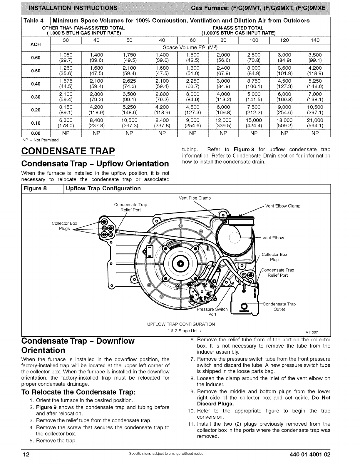
Table 4 Minimum Space Volumes for 100% Combustion, Ventilation and Dilution Air from Outdoors
OTHER THAN FAN-ASSISTEDTOTAL FAN-ASSISTEDTOTAL
(1,000'S BTUH GAS INPUT RATE) (1,000'S BTUH GAS INPUT RATE)
30 40 50 40 60 80 1O0 120 140
AOH Space Volume Ft3 (M3)
1,050 1,400 1,750 1,400 1,500 2,000 2,500 3,000 3,500
0.60 (29.7) (39.6) (49.5) (39.6) (42.5) (56.6) (70.8) (84.9) (99.1)
1,260 1,680 2,1 O0 1,680 1,800 2,400 3,000 3,600 4,200
0.50 (35.6) (47.5) (59.4) (47.5) (51.0) (67.9) (84.9) (101.9) (118.9)
1,575 2,1 O0 2,625 2,1 O0 2,250 3,000 3,750 4,500 5,250
0.40 (44.5) (59.4) (74.3) (59.4) (63.7) (84.9) (106.1 ) (127.3) (148.6)
2,1 O0 2,800 3,500 2,800 3,000 4,000 5,000 6,000 7,000
0.30 (59.4) (79.2) (99.1) (79.2) (84.9) (113.2) (141.5) (169.8) (198.1 )
3,150 4,200 5,250 4,200 4,500 6,000 7,500 9,000 10,500
0.20 (89.1) (118.9) (148.6) (118.9) (127.3) (169.8) (212.2) (254.6) (297.1)
6,300 8,400 10,500 8,400 9,000 12,000 15,000 18,000 21,000
0,10 (178.0) (237.8) (297.3) (237.8) (254.6) (339.5) (424.4) (509.2) (594.1)
0,00 NP NP NP NP NP NP NP NP NP
NP = Not Permitted
CONDENSATE TRAP
Condensate Trap - Upflow Orientation
tubing. Refer to Figure8 for upflow condensate trap
information. Refer to Condensate Drain section for information
how to install the condensate drain.
When the furnace is installed in the upflow position, it is not
necessary to relocate the condensate trap or associated
Figure 8 1Upflow Trap Configuration
Vent Pipe Clamp
Condensate Trap
Relief Port
Vent Elbow Clamp
Collector Box
Plugs
UPFLOW TRAP CONFIGURATION
Condensate Trap - Downflow
Orientation
When the furnace is installed in the downflow position, the
factory-installed trap will be located at the upper left corner of
the collector box. When the furnace is installed in the downflow
orientation, the factory-installed trap must be relocated for
proper condensate drainage.
To Relocate the Condensate Trap:
1. Orient the furnace in the desired position.
2. Figure 9 shows the condensate trap and tubing before
and after relocation.
3. Remove the relief tube from the condensate trap.
4. Remove the screw that secures the condensate trap to
the collector box.
5. Remove the trap.
1 & 2 Stage Units
6. Remove the relief tube from of the port on the collector
7. Remove the pressure switch tube from the front pressure
8. Loosen the clamp around the inlet of the vent elbow on
9. Remove the middle and bottom plugs from the lower
10. Refer to the appropriate figure to begin the trap
11. Install the two (2) plugs previously removed from the
Vent Elbow
Collector Box
Plug
Condensate Trap
Relief Port
Pressure Switch
Port
Outlet
P
Al1307
box. It is not necessary to remove the tube from the
inducer assembly.
switch and discard the tube. A new pressure switch tube
is shipped in the loose parts bag.
the inducer.
right side of the collector box and set aside. Do Not
Discard Plugs,
conversion.
collector box in the ports where the condensate trap was
removed.
12 Specificati ..... bject to change without notice. 440 01 4001 02
Page 13
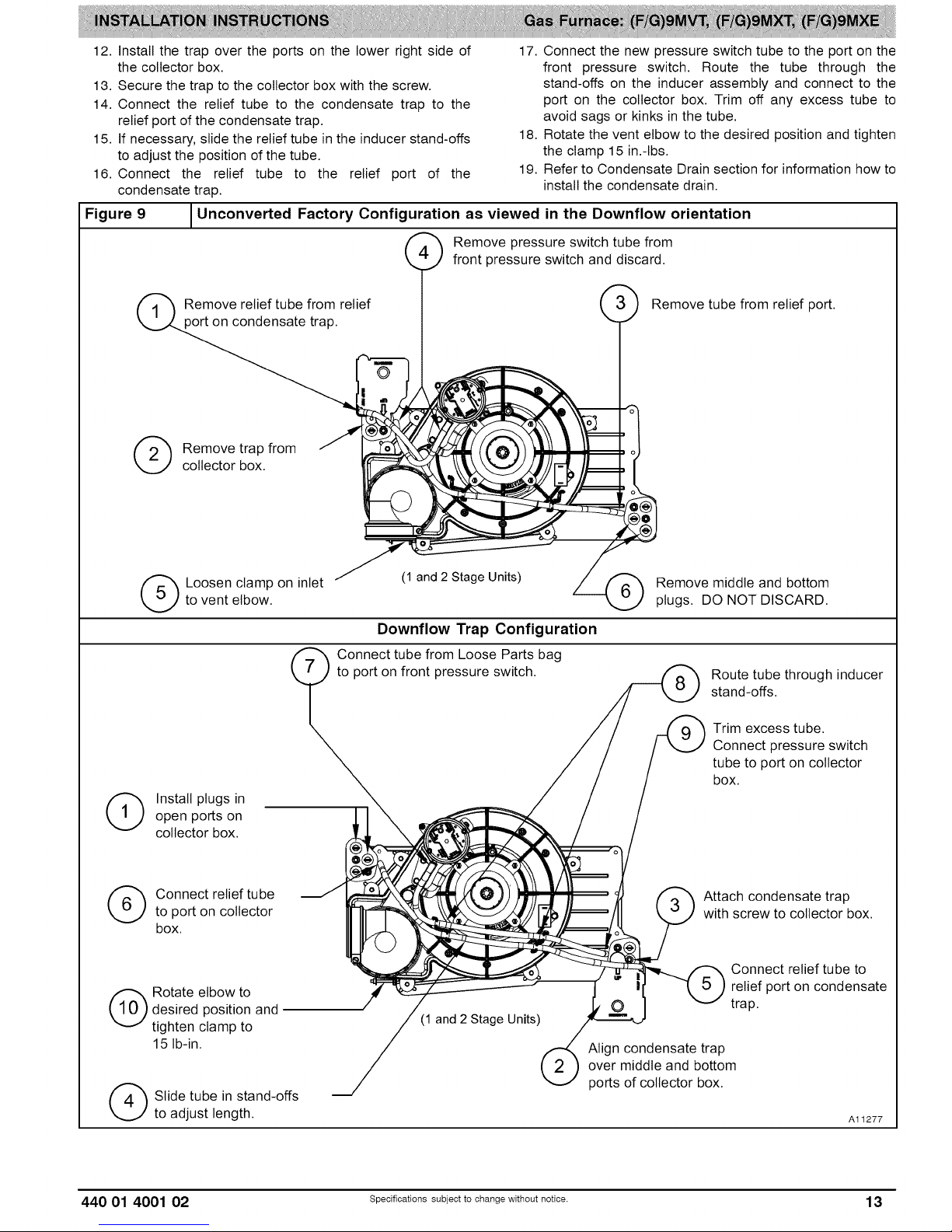
12. Install the trap over the ports on the lower right side of
the collector box.
13. Secure the trap to the collector box with the screw.
14. Connect the relief tube to the condensate trap to the
relief port of the condensate trap.
15. If necessary, slide the relief tube in the inducer stand-offs
to adjust the position of the tube.
16. Connect the relief tube to the relief port of the
condensate trap.
Figure 9
Unconverted Factory Configuration as viewed in the Downflow orientation
17. Connect the new pressure switch tube to the port on the
front pressure switch. Route the tube through the
stand-offs on the inducer assembly and connect to the
port on the collector box. Trim off any excess tube to
avoid sags or kinks in the tube.
18. Rotate the vent elbow to the desired position and tighten
the clamp 15 in.-Ibs.
19. Refer to Condensate Drain section for information how to
install the condensate drain.
Remove relief tube from relief Remove tube from relief port.
on condensate trap.
(_ emove trap from
collector box.
to vent elbow.
(_ Loosen clamp on inlet
(_ _ Remove pressure switch tube from
(1 and 2 Stage Units)
front pressure switch and discard.
Downflow Trap Configuration
Connect tube from Loose Parts bag
to port on front pressure switch.
Remove middle and bottom
plugs. DO NOT DISCARD.
Route tube through inducer
stand-offs.
(_ Install plugs inopen ports on
collector box.
(_ Connect relief tube
to port on collector
box.
desired position and
(_ otate elbow to
tighten clamp to
15 Ib-in.
(_ Slide tube in stand-offs
to adjust length.
Trim excess tube.
Connect pressure switch
tube to port on collector
box.
Attach condensate trap
with screw to collector box.
Connect relief tube to
relief port on condensate
trap.
(1 and 2 Stage Units)
Align condensate trap
over middle and bottom
ports of collector box.
Al1277
440 01 4001 02 Specificati ..... bject to change without notice. 13
Page 14
Condensate Trap - Horizontal
Orientation
When the furnace is installed in the horizontal right position, the
factory-installed trap will be located at the bottom of the
collector box. When the furnace is installed in the horizontal left
position, the factory-installed trap will be located at the top of
the collector box. The trap must be repositioned on the
collector box for proper condensate drainage.
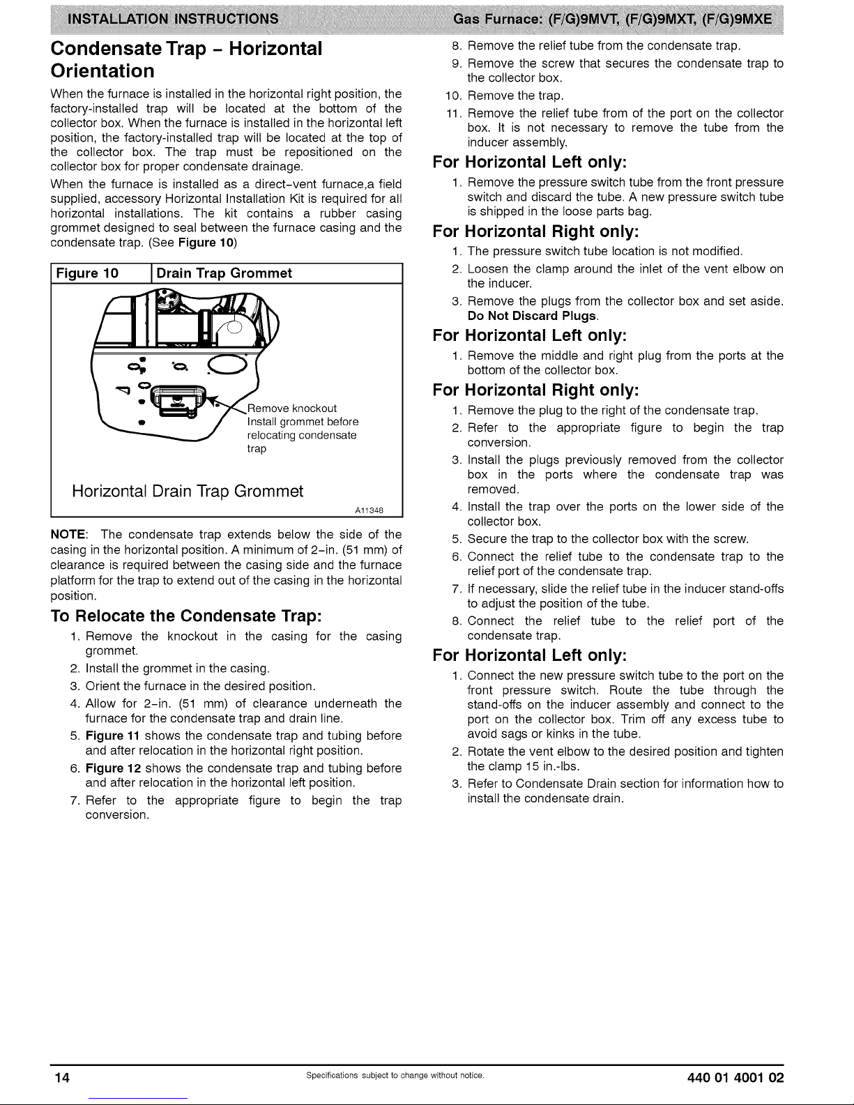
When the furnace is installed as a direct-vent furnace,a field
supplied, accessory Horizontal Installation Kit is required for all
horizontal installations. The kit contains a rubber casing
grommet designed to seal between the furnace casing and the
condensate trap. (See Figure 10)
Figure
NOTE: The condensate trap extends below the side of the
casing inthe horizontal position. A minimum of 2-in. (51 mm) of
clearance is required between the casing side and the furnace
platform for the trap to extend out of the casing in the horizontal
position.
To Relocate the Condensate Trap:
10 I Drain Trap Grommet
Remove knockout
Install grommet before
relocating condensate
trap
Horizontal Drain Trap Grommet
Al1348
1. Remove the knockout in the casing for the casing
grommet.
2. Install the grommet in the casing.
3. Orient the furnace in the desired position.
4. Allow for 2-in. (51 mm) of clearance underneath the
furnace for the condensate trap and drain line.
5. Figure 11 shows the condensate trap and tubing before
and after relocation in the horizontal right position.
6. Figure 12 shows the condensate trap and tubing before
and after relocation in the horizontal left position.
7. Refer to the appropriate figure to begin the trap
conversion.
8. Remove the relief tube from the condensate trap.
9. Remove the screw that secures the condensate trap to
the collector box.
10. Remove the trap.
11. Remove the relief tube from of the port on the collector
box. It is not necessary to remove the tube from the
inducer assembly.
For Horizontal Left only:
1. Remove the pressure switch tube from the front pressure
switch and discard the tube. A new pressure switch tube
is shipped in the loose parts bag.
For Horizontal Right only:
1. The pressure switch tube location is not modified.
2. Loosen the clamp around the inlet of the vent elbow on
the inducer.
3. Remove the plugs from the collector box and set aside.
Do Not Discard Plugs.
For Horizontal Left only:
1. Remove the middle and right plug from the ports at the
bottom of the collector box.
For Horizontal Right only:
1. Remove the plug to the right of the condensate trap.
2. Refer to the appropriate figure to begin the trap
conversion.
3. Install the plugs previously removed from the collector
box in the ports where the condensate trap was
removed.
4. Install the trap over the ports on the lower side of the
collector box.
5. Secure the trap to the collector box with the screw.
6. Connect the relief tube to the condensate trap to the
relief port of the condensate trap.
7. If necessary, slide the relief tube in the inducer stand-offs
to adjust the position of the tube.
8. Connect the relief tube to the relief port of the
condensate trap.
For Horizontal Left only:
1. Connect the new pressure switch tube to the port on the
front pressure switch. Route the tube through the
stand-offs on the inducer assembly and connect to the
port on the collector box. Trim off any excess tube to
avoid sags or kinks in the tube.
2. Rotate the vent elbow to the desired position and tighten
the clamp 15 in.-Ibs.
3. Refer to Condensate Drain section for information how to
install the condensate drain.
14 Specificati..... bject to change withoutnotice. 440 01 4001 02
Page 15
Figure 11 _Unconverted Factory Configuration as viewed in the Horizontal Right Orientation
(_ emove plug from
(_ ttach condensate
collector box.
DO NOT DISCARD.
trap with screw to
collector box.
\
(1AND 2 STAGE UNITS)
Horizontal Right Trap Configuration
Slide relief tube in stand-offs
to adjust length.
If alternate vent position
is required, loosen clamp
on inlet of vent elbow.
Remove trap from
collector box.
Vent elbow shown in alternate
orientation. Tighten clamp on
inlet to vent elbow 15 lb.-in.
open port on
(_ Install plug in
collector box.
440 01 4001 02 Specificati..... bject to change withoutnotice. 15
(1 AND 2 8"rAGEuNrm)
Align trap over middle and
right-hand post on collector box.
Al1402
Page 16
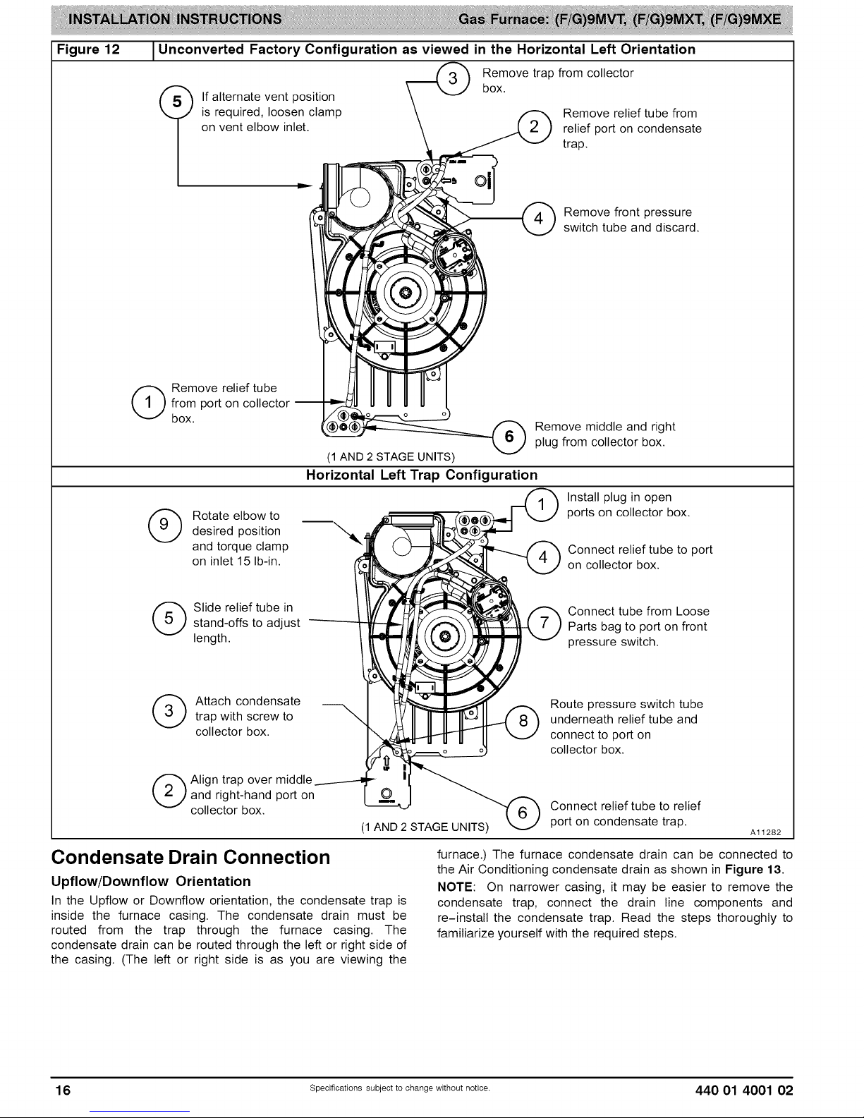
Figure 12 1Unconverted Factory Configuration as viewed in the Horizontal Left Orientation
Remove trap from collector
is required, loosen clamp
on vent elbow inlet.
t f alternate vent position box.
ID
from port on collector --
(_ emove relief tube
box.
(1 AND 2 STAGE UNITS)
Horizontal Left Trap Configuration
(_ otate elbow todesired position
and torque clamp
on inlet 15 Ib-in.
Remove relief tube from
relief port on condensate
trap.
Remove front pressure
switch tube and discard.
Remove middle and right
plug from collector box.
Install plug in open
ports on collector box.
Connect relief tube to port
on collector box.
(_ Slide relief tube instand-offs to adjust
length.
(_ ttach condensate
trap with screw to
collector box.
and right-hand port on
(_ Align trap over middle
collector box.
(1 AND 2 STAGE UNITS)
Condensate Drain Connection
Upflow/Downflow Orientation
In the Upflow or Downflow orientation, the condensate trap is
inside the furnace casing. The condensate drain must be
routed from the trap through the furnace casing. The
condensate drain can be routed through the left or right side of
the casing. (The left or right side is as you are viewing the
Connect tube from Loose
Parts bag to port on front
pressure switch.
Route pressure switch tube
underneath relief tube and
connect to port on
collector box.
Connect relief tube to relief
port on condensate trap.
Al1282
furnace.) The furnace condensate drain can be connected to
the Air Conditioning condensate drain as shown in Figure 13.
NOTE: On narrower casing, it may be easier to remove the
condensate trap, connect the drain line components and
re-install the condensate trap. Read the steps thoroughly to
familiarize yourself with the required steps.
16 specificati..... bject to change withoutnotice. 440 01 4001 02
Page 17

Figure13
Example of Field Drain Attachment
OPEN STAND
PIPE FOR
A/C OR
HUMIDIFIER
DRAIN
U
i_==-=TEE
TO OPEN
DRAIN
"-1
For Right Side Condensate Drain:
1. Remove the 7/9-in. knock-out from the right side of the
casing. (See Figure 14)
2. Remove the pre-formed drain tube and two spring
clamps from the loose parts bag.
3. Slide a spring clamp 1-in. down the plain end of the
drain tube.
4. From inside the casing, insert the formed grommet end
of the tube through the 7/8-in. knockout in the casing.
5. Pull the tube through the casing from the outside until it is
seated in the knockout
6. Attach the plain end of the drain tube to the outlet stub
on the drain trap. Secure the drain tube to the trap with
the spring clamp.
7. Slide a spring clamp over the open end of the drain tube
outside the casing.
8. Open the spring clamp and connect a field-supplied
1/2-in. CPVC street elbow to the open end of the drain
tube.
9. Connect additional 1/2-in. CPVC piping to a condensate
pump approved for use with acidic furnace condensate
or to a code-approved drain.
For Left Side Condensate Drain Connection:
1. For left side condensate drainage, the drain line is routed
from the condensate trap, behind the inducer and out
through the left side of the casing. A pre-formed "Z" pipe
is provided in the loose parts bag shipped with the
furnace. The "Z" pipe is long enough to extend out of the
casing on the 14 3/16-in. (360 mm) wide furnace. Larger
casings will require a field supplied CPVC pipe and to
extend the drain line out of the furnace.
2. The "Z" pipe is connected to the condensate trap by
modifying the formed rubber drain tube. Connect the
drain line as shown below:
3. Remove the knock-out from the left side of the casing.
(See Figure 14)
Al1276
4. Install the grommet for the 1/2-in. CPVC drain line in the
7/8-in. knockout in the casing.
5. Remove the pre-formed drain tube, the offset 1/2-in.
CPVC pipe and two spring clamps from the loose parts
bag.
6. Remove the formed grommet on the tube by cutting the
tube along the vertical line located about 1-in. away from
the formed grommet. (See Figure 15)
7. Slide a spring clamp 1-in. down the plain end of the
drain tube
8. With the bend in the tube oriented horizontally and plain
end of the tube pointing away from you, insert the 1/2-in
CPVC pipe into the other end of the drain tube. Rotate
the tube so the offset in the tube points away from you.
Slide a spring clamp over the open end of the 1/2-in.
CPVC tube and secure the cut end of drain tube to the
pipe.
9. Prime the bare end of the pipe with CPVC primer.
10. Route the offset pipe behind the inducer assembly and
through the grommet in the casing, if the "Z" pipe is long
enough. If the "Z" pipe is not long enough, continue with
installation.
11. Attach the plain end of the drain tube to the outlet stub
on the drain trap. Secure the drain tube to the trap with
the spring clamp.
12. If the "Z" pipe does not extend through the casing, slide a
piece of field supplied CPVC through the grommet in the
casing, otherwise, go to Step 17.
13. Cement a 1/2-in. CPVC coupling to the end of the CPVC
pipe.
14. Apply cement to the end of the "Z" pipe connected to the
condensate trap.
15. Connect the field-supplied CPVC pipe to the CPVC pipe
connected to the condensate trap.
16. Cut off excess CPVC pipe outside the casing.
17. Connect additional 1/2-in. CPVC piping to a condensate
pump approved for use with acidic furnace condensate
or to a code-approved drain.
18.
When a condensate pump is not used, slope the pipe
away from the furnace to allow for proper drainage.
Figure 14
JKnockout Removal
o
¢
Al1305
CUT HAZARD
Failure to follow this caution may result in personal
injury.
Sheet metal parts may have sharp edges or burrs. Use
care and wear appropriate protective clothing, safety
glasses and gloves when handling parts, and servicing
furnaces.
440 01 4001 02 specifioati..... bject to change withoutnotice. 17
Page 18

Figure 15
Modify Drain Tube
Cutand removeformed end of
draintube for left sideand horizontal
drainconnection
\
RIGHT SIDE DRAIN ELBOW
7. Slide the other spring clamp down the plain end of the
drain tube.
8. Connect additional 1/2-in. CPVC piping to a condensate
pump approved for use with acidic furnace condensate
or to a code-approved drain.
9. When a condensate pump is not used, slope the pipe
away from the furnace to allow for proper drainage.
Figure 17 I Formed Tube Grommet
INSTALL CLAMPS ON DRAIN TUBE
ATTACH DRAIN TUBETO CONDENSATF---- 7
DRAIN TRAP /
PULL DRAIN STUB
THROUGH CASING
Al1388
Figure 16 1Drain Trap Connection and Routing
Attach tube to condensate trap
Cut formed end off \
condensate drain tube \
Field supplied 1/2"CPVC Connect short end _ 2 _' _=l_.
_7UlPl_ng2t,,d:a in ext e nsio n. of "Z"pipe to modified\[_ \" ill
TRAP, DRAIN ELBOW WITH DISCHARGE PIPE
Modified drain tube connect to
condensate trap and "Z" pipe
Field supplied 1/2"
CPVC to drain
Casing grommet from Field-supplied 1/2"CPVC coupling & drain
loose parts bag pipe 17 1/2" 21"and 24 1/2"casings
i _ET etr_ mDAkM D_I ITem D_J_Mr_ kMml IP_D
\
Al1344
Horizontal Orientation
1. In the Horizontal orientation, a field supplied accessory
drain trap grommet is required to seal the gap between
the casing and the condensate trap. The condensate
trap outlet extends 2-in. (51 mm) below the furnace
casing. To allow for servicing the trap, the condensate
drain tube in the loose parts bag can be modified to
make a coupler to allow for future service of the
condensate trap and drain line.
2. Remove the knock-out for the condensate trap in the
side of the casing.
3. Install the drain trap grommet in the casing. If necessary,
remove the trap, install the grommet and re-install the
trap.
4. Remove the pre-formed drain tube, the offset 1/2-in.
CPVC pipe and two spring clamps from the loose parts
bag.
5. Remove the formed grommet on the tube to create an
elbow or straight connector. (See Figure 17)
6. Connect the cut tube to the outlet of the condensate trap
with 1 spring clamp.
//
//
\\\\\
OPEN SPRING CLAMP
INSERT FIELD - SUPPLIED
1/2'" CPVC DRAIN PIPE
* CLAMP MAY BE LOCATED
ON OUTSIDE OF DRAIN TUBE
RIGHT SIDE DRAIN INSTALLATION
Al1342
NSTALLATION
UPFLOW INSTALLATION
NOTE: The furnace must be pitched forward as shown in
Figure 18 for proper condensate drainage.
Figure 18 /Furnace Pitch Requirements
LEVEL0-IN. (0 MM)TO
1/2-1N.(13 MM) MAX
MIN 1/4-IN.(6 MM) TO
1/2-1N.(13 MM) MAX
FRONT
UPFLOW OR
DOWNFLOW HORIZONTAL Al1237
Supply Air Connections
For a furnace not equipped with a cooling coil, the outlet duct
shall be provided with a removable access panel. This opening
shall be accessible when the furnace is installed and shall be of
such a size that the heat exchanger can be viewed for possible
openings using light assistance or a probe can be inserted for
sampling the air stream. The cover attachment shall prevent
leaks.
18 Specificati ..... bject to change without notice. 440 01 4001 02
Page 19

Connect supply-air duct to flanges on furnace supply-air
outlet. Bend flange upward to 90 ° with wide duct pliers. (See
Figure 22) The supply-air duct must be connected to ONLY
the furnace supply-outlet-air duct flanges or air conditioning
coil casing (when used). DO NOT cut main furnace casing side
to attach supply air duct, humidifier, or other accessories. All
accessories MUST be connected to duct external to furnace
main casing.
Return Air Connections
FIRE HAZARD
A failure to follow this warning could cause personal
injury, death and/or property damage.
Never connect return-air ducts to the back of the
furnace. Follow instructions below.
The return-air duct must be connected to bottom, sides (left or
right), or a combination of bottom and side(s) of main furnace
casing as shown in Figure27, Figure28 and Figure29,
Bypass humidifier may be attached into unused return air side
of the furnace casing.
Bottom Return Air Inlet
These furnaces are shipped with bottom closure panel installed
in bottom return-air opening. Remove and discard this panel
when bottom return air is used. To remove bottom closure
panel, perform the following:
1. Tilt or raise furnace and remove four (4) screws holding
bottom plate. (See Figure 19)
2. Remove bottom plate.
3. Remove bottom closure panel.
4. Reinstall bottom plate and screws.
Figure 19 |Removing Bottom Closure Panel
I
.L
'>,
4 _" _ BOTTOM
c,osoRE
PANEL
openings in DOWNFLOW configuration. (See Figure27,
Figure 28 and Figure 29)
Leveling Legs (If Desired)
In upflow position with side return inlet(s), leveling legs may be
used. (See Figure 20) Install field-supplied, 5/16 x 1-1/2-in. (8
x 38 mm) (max) corrosion-resistant machine bolts, washers
and nuts.
Figure 20 1Leveling Legs
5/
(8ram)
1 3/4'
(44mrn)
1 3/4"
(44mrn)
(8mrn)
5/16"
(8mm)
(44mm) 1 3/41'
(44mm) 1
A89014
NOTE: Bottom closure must be used when leveling legs are
used. It may be necessary to remove and reinstall bottom
closure panel to install leveling legs. To remove bottom closure
panel, see Step 1 in Bottom Return Air Inlet section.
To install leveling legs:
1. Position furnace on its back. Locate and drill a hole in
each bottom corner of furnace.
2. For each leg, install nut on bolt and then install bolt with
nut in hole. (Install flat washer if desired.)
3. Install another nut on other side of furnace base. (Install
flat washer if desired.)
4. Adjust outside nut to provide desired height, and tighten
inside nut to secure arrangement.
5. Reinstall bottom closure panel if removed.
DOWN FLOW INSTALLATION
NOTE: The furnace must be pitched forward as shown in
Figure 18 for proper condensate drainage.
BOTTOM
PLATE
Side Return Air Inlet
These furnaces are shipped with bottom closure panel installed
in bottom return-air opening. This panel MUST be in place
when only side return air is used.
NOTE: Side return-air openings can be used in UPFLOW and
most HORIZONTAL configurations. Do not use side return-air
440 01 4001 02 Specificati ..... bject to change without notice. 19
Lll F004
Supply Air Connections
NOTE: For downflow applications, this furnace is approved for
use on combustible flooring when any one of the following
three accessories are used (see specification sheets for list of
approved accessories):
• Special Base - NAHA01101SB
• Cased Coil Assembly- END4X, ENW4X
1. Determine application being installed from Table 5.
2. Construct hole in floor per Table 5 and Figure 21.
3. Construct plenum to dimensions specified in Table 5
and Figure 21.
Page 20

4. InstallasshowninFigure23.IfCoilAssemblyPartis
used,installasshowninFigure24.
Figure 21
Floor and Plenum Opening
Dimensions
CUT HAZARD
Failure to follow this caution may result in personal
injury.
Sheet metal parts may have sharp edges or burrs. Use
care and wear appropriate protective clothing, safety
glasses and gloves when handling parts, and servicing
furnaces.
Connect supply-air duct to supply-air outlet on furnace. Bend
flange inward past 90 ° with wide duct pliers (See Table 1
Figure 22) The supply-air duct must be connected to ONLY
the furnace supply outlet or air conditioning coil casing (when
used). When installed on combustible material, supply-air duct
must be connected to ONLY the factory-approved accessory
subbase, or a factory-approved air conditioning coil casing. DO
NOT cut main furnace casing to attach supply side air duct,
humidifier, or other accessories. All accessories MUST be
connected to duct external to furnace casing.
Return Air Connections
A96283
NOTE: It is recommended that the perforated supply-air duct
flanges be completely removed from furnace when installing
the furnace on a factory-supplied cased coil or coil box. To
remove the supply-air duct flange, use wide duct pliers or hand
seamers to bend flange back and forth until it breaks off. Be
careful of sharp edges. (See Figure 22)
Figure 22 I Duct Flanges
UPFLOW DOWN FLOW HORIZONTAL
PERFORATED
DISCHARGE DUCT
NGE
L - -
i i
\
120 '_ YES 120 °'_,_
MIN MIN
FIRE HAZARD
A failure to follow this warning could cause personal
injury, death and/or property damage.
Never connect return-air ducts to the back of the
furnace. Follow instructions below.
The return-air duct must be connected to return-air opening
(bottom inlet) as shown in Figure 27. DO NOT cut into casing
sides (left or right). Bypass humidifier connections should be
made at ductwork or coil casing sides exterior to furnace. (See
Figure 27)
/
L _ _
YES
\
YES
YES
L _
120_
MIN
YES
YES
20 Specificati ..... bject to change without notice. 440 01 4001 02
NO
NO
NO
A1049[
Page 21

Table 5
FURNACE
CASING WIDTH
IN, (mm)
Opening Dimensions - in. (mm)
PLENUM OPENING FLOOR OPENING
APPLICATION
A B C D
12-11/1
Upflow Applications on Combustible or Noncombustible Flooring 6 21-5/8 13-5/16 22-1/4
(subbase not required) (322) (549) (338) (565)
Downflow Applications on Noncombustible Flooring 12-9/16 19 13-3/16 19-5/8
14-3/16 (subbase not required) (319) (483) (335) (498)
(360) 11-13/1 19 13-7/16 20-5/8
Downflow applications on combustible flooring (subbase required) 6
(284) (483) (34t) (600)
Downflow Applications on Combustible Flooring with Coil Assembly or 12-5/16 19 13-5/16 20
coil box (subbase not required) (319) (483) (338) (508)
Upflow Applications on Combustible or Noncombustible Flooring 16 21-5/8 16-5/8 22-1/4
(subbase not required) (406) (549) (422) (565)
Downflow Applications on Noncombustible Flooring 15-7/8 19 16-1/2 19-5/8
17-1/2 (subbase not required) (403) (483) (419) (498)
(445) 15-1/8 19 16-3/4 20-5/8
Downflow applications on combustible flooring (subbase required) (384) (483) (425) (600)
Downflow Applications on Combustible Flooring with Coil Assembly or coil 15-1/2 19 16-1/2 20
box (subbase not required) (394) (483) (419) (508)
Upflow Applications on Combustible or Noncombustible Flooring 19-1/2 21-5/8 20-1/8 22-1/4
(subbase not required) (495) (549) (511) (565)
Downflow Applications on Noncombustible Flooring 19-3/8 19 20 19-5/8
21 (subbase not required) (492) (483) (508) (498)
(533) Downflow applications on combustible flooring 18-5/8 19 20-1/4 20-5/8
(subbase required) (473) (483) (514) (600)
Downflow Applications on Combustible Flooring with Coil Assembly or coil 19 19 20 20
box (subbase not required) (483) (483) (508) (508)
Upflow Applications on Combustible or Noncombustible Flooring 23 21-1/8 23-5/8 22-1/4
(subbase not required) (584) (537) (600) (565)
Downflow Applications on Noncombustible Flooring 22-7/8 19 23-1/2 19-5/8
24-1/2 (subbase not required) (581) (483) (597) (498)
(622) Downflow applications on Combustible flooring 22-1/8 19 23-3/4 20-5/8
(subbase required) (562) (483) (603) (600)
Downflow Applications on Combustible Flooring with Coil Assembly or 22-1/2 19 23-1/2 20
coil box (subbase not required) (572) (483) (597) (508)
Figure 23
Installed on a Combustible Floor
IFurnace, Plenum, and Subbase
FURNACE
(OR COIL CASING
WHEN USED)
/_ COMBUSTIBLE
FLOORING
SUBBASE
SHEET METAL
PLENUM
-- FLOOR
OPENING
A96285
Figure 24
Furnace, Plenum, and Coil
Assembly on a Combustible Floor
FURNACE
CD5 OR CK5
COIL ASSEMBLY
OR KCAKC
COIL'BOX
COMBUSTIBLE
FLOORING
/
SHEET METAL
PLENUM _.
FLOOR
OPENING
A96284
440 01 4001 02 Specificati ..... bject to change without notice. 21
Page 22

Bottom Return Air Inlet
These furnaces are shipped with bottom closure panel installed
in bottom return-air opening. Remove and discard this panel
when bottom return air is used. To remove bottom closure
panel, perform the following:
1. Tilt or raise furnace and remove four (4) screws holding
bottom plate. (See Figure 19)
2. Remove bottom plate.
3. Remove bottom closure panel.
4. Reinstall bottom plate and screws.
HORIZONTAL INSTALLATION
NOTE: The furnace must be pitched forward as shown in
Figure 18 for proper condensate drainage.
FIRE, EXPLOSION, AND CARBON MONOXIDE
POISONING HAZARD
Failure to follow this warning could result in personal
injury, death, or property damage.
Do not install the furnace on its back or hang furnace with
control compartment facing downward. Safety control
operation will be adversely affected. Never connect
return-air ducts to the back of the furnace.
The furnace can be installed horizontally in an attic or
crawlspace on either the left-hand (LH) or right-hand (RH)
side. The furnace can be hung from floor joists, rafters or
trusses or installed on a non-combustible platform, blocks,
bricks or pad.
Suspended Furnace Support
The furnace may be supported under the entire length of the
furnace with threaded rod and angle iron. (See Figure 25)
Secure angle iron to bottom of furnace as shown.
Platform Furnace Support
Construct working platform at location where all required
furnace clearances are met. (See Table 1 and Figure 26) For
furnaces with 1-in. (25 mm) clearance requirement on side, set
furnace on non-combustible blocks, bricks or angle iron. For
crawlspace installations, if the furnace is not suspended from
the floor joists, the ground underneath furnace must be level
and the furnace set on blocks or bricks.
Figure 25 JSuspended Furnace Installation
NOTE: EXTEND ANGLE
IRON OUT FOR
COIL SUPPORT
ROD LOCATION /
USING DIMPLE /
LOCATORS
HEX NUT
& WASHER (4)
REQD. PER ROD
COMBUSTION - AiR PiPE
-- (SEE VENTING SECTION)
_!ENT
,IN ROD
NOTES: 1. A 1 In. (25mm) clearance minimum between
top of furnace and combustible material
2. The entire length of furnace must be
supported when furnace is used in horizontal
position to ensure proper drainage.
3. Furnace shown is a direct vent application.
Refer to the Venting section for agowable vent
configurations. Al1155
22 Specificati ..... bject to change without notice. 440 01 4001 02
Page 23

Figure 26
Working Platform for Attic Installation
COMBUSTION - AIR PIPE
(SEE VENTING SECTION)
A 12-1N, (305 ram) MIN HORIZONTAL PIPE
SECTION IS RECOMMENDED WITH A
SHORT (5 TO 8 FT / 1,5 TO 2,4 M) VENT
SYSTEM TO REDUCE EXCESSIVE
CONDENSATE DROPLETS FROM
EXITING THE VENT PIPE,
INDOOR
COIL
VENT
30" (762 mrn)
Min Work Area
ROLLOUT PROTECTION REQUIRED
Install 1.2" x 22" (305 x 559 mm) sheet
metal in front of burner compartment
area.
CONDENSATE
TRAP
NOTE: FURNACE SHOWN AS DIRECT VENT APPLICATION. REFER TO THE
VENTING SECTION FOR ALLOWABLE VENT CONFIGURATIONS
Roll-Out Protection
Provide a minimum 12-in. x 22-in. (305 x 559 mm) piece of
sheet metal for flame roll-out protection in front of burner area
for furnaces closer than 12-in. (305 mm) above the
combustible deck or suspended furnaces closer than 12-in.
(305mm) to joists. The sheet metal MUST extend underneath
the furnace casing by 1-in. (25mm) with the door removed.
The bottom closure panel may be used for flame roll-out
protection when bottom of furnace is used for return air
connection. See Figure 26 for proper orientation of roll-out
shield.
Supply Air Connections
For a furnace not equipped with a cooling coil, the outlet duct
shall be provided with a removable access panel. This opening
shall be accessible when the furnace is installed and shall be of
such a size that the heat exchanger can be viewed for possible
openings using light assistance or a probe can be inserted for
sampling the air stream. The cover attachment shall prevent
leaks.
Connect supply-air duct to flanges on furnace supply-air
outlet. Bend flange upward to 90 ° with wide duct pliers. (See
Figure 22) The supply-air duct must be connected to ONLY
the furnace supply-outlet-air duct flanges or air conditioning
coil casing (when used). DO NOT cut main furnace casing side
to attach supply air duct, humidifier, or other accessories. All
accessories MUST be connected to duct external to furnace
main casing.
Al1154
Return Air Connections
The return-air duct must be connected to bottom of the
furnace. The side of casing that faces downward may also be
used for return air connection. A combination of the bottom
and downward facing side may also be used. The side of the
casing cannot be used as a return air connection. Bypass
humidifier may be attached into unused return air side of the
furnace casing. (See Figure 29)
Bottom Return Air Inlet
These furnaces are shipped with bottom closure panel installed
in bottom return-air opening. Remove and discard this panel
when bottom return air is used. To remove bottom closure
panel, perform the following:
1. Tilt or raise furnace and remove four (4) screws holding
bottom plate. (See Figure 19)
2. Remove bottom plate.
3. Remove bottom closure panel.
4. Reinstall bottom plate and screws.
Side Return Air Inlet
These furnaces are shipped with bottom closure panel installed
in bottom return-air opening. This panel MUST be in place
when side return air inlet(s) are used without a bottom return air
inlet.
Not all horizontal furnaces are approved for side return air
connections (See Figure 29)
440 01 4001 02 Specificati ..... bject to change without notice. 23
Page 24

Filter Arrangement
FIRE, CARBON MONOXIDE AND POISONING
HAZARD
Failure to follow this warning could result in personal
injury, or death.
Never operate a furnace without a filter or filtration device
installed. Never operate a furnace with filter or filtration
device access doors removed.
Furnaces shipped without a filter rack:
There are no provisions for an internal filter in these furnaces.
An external filter rack is required and is purchased separately.
A field supplied accessory air cleaner may also be used in
place of the filter rack.
For upflow applications, the filter can be installed on either side
of the furnace, the bottom of the furnace or any combination of
side and bottom of the furnace. (See Figure 28, Figure 30, and
Figure 31)
For downftow applications, the filter rack (or field supplied
accessory air cleaner) must only be connected to the bottom
opening on the furnace (See Figure 27 and Figure 31 and
Table 7).
For horizontal applications, the filter rack (or field supplied
accessory air cleaner) can be connected to the bottom opening
on the furnace. For side return use in the horizontal position,
refer to Figure 29. If both side and bottom openings are used in
Figure 29, each opening used will require a filter.
A filter rack or any field supplied accessory air cleaner can also
be installed in the common return duct prior to entering the
return air opening in any orientation.
See Table 6 for recommended filter size details.
Table 6 Filter Size Information - in. (mm)
FURNACE
CASING
WIDTH
14--3/16 16 x 25 x 3/4 14 x 25 x 3/4 Washable*
(360) (406 x 635 x 19) (356 x 635 x 19)
17-1/2 16 x 25 x 3/4 16 x 25 x 3/4 Washable*
(445) (406 x 635 x 19) (406 x 635 x 19)
21 (533) (406 x 635 x 19) (508 x 635 x 19)
24-1/2 16 x 25 x 3/4 24 x 25 x 3/4 Washable*
(622) (406 x 635 x 19) (610 x 635 x 19)
* Recommended to maintain air filter face velocity. See Product Data for part
number.
SIDE RETURN
16 x 25 x 3/4 20 x 25 x 3/4 Washable*
Refer to the instructions supplied with the Filter Rack or
accessory air filter for additional assembly and installation
options.
FILTERSIZE
BOTTOM
RETURN
FILTER
TYPE
Figure 27 Configurations and Restrictions
£1DE RETURN
NOT pERMITTED
JDownflow Return Air
O
®
®
Upflow Return Air Configurations
Figure 28 and Restrictions
® ®
® ®
®
RETURN
AIR
RETURN AIR
Lt0F032
Figure 29
AIR _!_ RESTRICTIONS
RETURN T UPFLOW
Horizontal Return Air
Configurations and Restrictions
I
)
L10F033
24 Specificati ..... bject to change without notice. 440 01 4001 02
RETURN
AIR
* NOTE: RESTRICTION SAME FOR
HORIZONAL LEFT
HORIZONAL
RETURN AIR
RESTRICTIONS
SUPPLY
AIR
24
O
L10F034
Page 25

External Filter Cabinet Configurations
Figure 30 _Accessory Side Filter Rack
L10F027
Figure 31 Accessory Bottom Filter Rack
0
® @
@ ®
Lt0F031
B
A
m
o
_D,,_ _,_--1 1/4 '' /I TABS
/ I (TYP.) I
I ........................ I
"=--1 1/4"
..._ ,,i 251/8" =1
17
._,,1_,,i_ 3/8, ' 1/2"--_
23 1/8"
OPENING
16/8"
14 1/2"
OPE i NG !
2 3/8"
t
e
,3
A
22-5/t 6
(566.4)
o
.3
o
o
o
o
I
28-7/16
(722.2)
e
e
e
e
2-3/t 6 - .,,._=.
(55.5)
Table 7 Dimensional Drawing - in. (mm)
KIT NO. A B
NAH B00501FF 14-3/16 11-3/8 14-1/4
NAHB00601 FF 17-1/2 14-5/8 17-5/8
NAHB00701FF
NAH B00801FF 24-1/2 21-5/8 24-5/8
FURNACE
WIDTH
(360.4) (289) (362)
(444.5) (371.5) (447.7)
21 18-1/8 21-1/8
(533.4) (460.4) (536.6)
(622.3) (549.3) (625.5)
o
440 01 4001 02 Specificati ..... bject to change without notice. 25
Page 26

Air Ducts
General Requirements
The duct system should be designed and sized according to
accepted national standards such as those published by: Air
Conditioning Contractors Association (ACCA), Sheet Metal and
Air Conditioning Contractors National Association (SMACNA)
or American Society of Heating, Refrigerating and Air
Conditioning Engineers (ASHRAE) or consult The Air Systems
Design Guidefines reference tables available from your local
distributor. The duct system should be sized to handle the
required system design CFM at the design external static
pressure. The furnace airflow rates are provided in the Service
and Technical Support Manual. When a furnace is installed
so that the supply ducts carry air circulated by the furnace to
areas outside the space containing the furnace, the return air
shall also be handled by duct(s) sealed to the furnace casing
and terminating outside the space containing the furnace.
Secure ductwork with proper fasteners for type of ductwork
used. Seal supply- and return-duct connections to furnace
with code approved tape or duct sealer.
NOTE: Flexible connections should be used between ductwork
and furnace to prevent transmission of vibration.
Ductwork passing through unconditioned space should be
insulated to enhance system performance. When air
conditioning is used, a vapor barrier is recommended.
Maintain a 1-in. (25 mm) clearance from combustible materials
to supply air ductwork for a distance of 36-in. (914 mm)
horizontally from the furnace. See NFPA 90B or local code for
further requirements.
Ductwork Acoustical Treatment
NOTE: Metal duct systems that do not have a 90 degree elbow
and 10 ft. (3 M) of main duct to the first branch take-off may
require internal acoustical lining. As an alternative, fibrous
ductwork may be used if constructed and installed in
accordance with the latest edition of SMACNA construction
standard on fibrous glass ducts. Both acoustical lining and
fibrous ductwork shall comply with NFPA 90B as tested by UL
Standard 181 for Class 1 Rigid air ducts.
NOTE: For horizontal applications, the top most flange may be
bent past 90 ° to allow the evaporator coil to hang on the
flange temporarily while the remaining attachment and sealing
of the coil are performed.
GAS PIPING
FIRE OR EXPLOSION HAZARD
Failure to follow this warning could result in personal
injury, death, and/or property damage.
Never purge a gas line into a combustion chamber.
Never test for gas leaks with an open flame. Use a
commercially available soap solution made specifically
for the detection of leaks to check all connections. A
fire or explosion may result causing property damage,
personal injury or loss of life.
FIRE OR EXPLOSION HAZARD
Failure to follow this warning could result in personal
injury, death, and/or property damage.
Gas valve inlet and/or inlet pipe must remain capped
until gas supply line is permanently installed to protect
the valve from moisture and debris. Also, install a sedi-
ment trap in the gas supply piping at the inlet to the
gas valve.
Gas piping must be installed in accordance with national and
local codes. Refer to current edition of NFGC in the U.S.A.
Refer to current edition of CAN/CSA B149.1 in Canada.
Installations must be made in accordance with all authorities
having jurisdiction. If possible, the gas supply line should be a
separate line running directly from meter to furnace.
NOTE: Use a back-up wrench on the inlet of the gas valve
when connecting the gas line to the gas valve.
NOTE: In the state of Massachusetts:
1. Gas supply connections MUST be performed by a
licensed plumber or gas fitter.
2. When flexible connectors are used, the maximum length
shall not exceed 36-in. (915 mm).
3. When lever handle type manual equipment shutoff
valves are used, they shall be T-handle valves.
4. The use of copper tubing for gas piping is NOT approved
by the state of Massachusetts.
Refer to Table 8 for recommended gas pipe sizing. Risers must
be used to connect to furnace and to meter. Support all gas
piping with appropriate straps, hangers, etc. Use a minimum of
1 hanger every 6 ft. (1.8 M). Joint compound (pipe dope)
should be applied sparingly and only to mate threads of joints.
Pipe dope must be resistant to the action of propane gas.
FIRE OR EXPLOSION HAZARD
A failure to follow this warning could result in personal in-
jury, death, and/or property damage.
If local codes allow the use of a flexible gas appliance
connector, always use a new listed connector. Do not use
a connector which has previously served another gas ap-
31lance. Black iron pipe shall be installed at the furnace
gas control valve and extend a minimum of 2-in. (51 mm)
outside the furnace.
FURNACE DAMAGE HAZARD
Failure to follow this caution may result in furnace dam-
age.
Connect gas pipe to furnace using a backup wrench to
avoid damaging gas controls and burner misalignment.
FIRE OR EXPLOSION HAZARD
Failure to follow this warning could result in personal
injury, death, and/or property damage.
Use proper length of pipe to avoid stress on gas con-
tro man fo d and a gas eak.
26 Specifications subject to change without notice. 440 01 4001 02
Page 27

Table 8
NOMINAL
IRONPIPE
SIZE
IN.(aM)
1/2(13)
3/4(19)
1(25)
1-1/4(32)
1-1/2(39)
Cubic ft of gas per hr for gas pressures of 0.5 psig (14-in. w.c.) or less and
a pressure drop of 0.5-in. w.c. (based on a 0.60 specific gravity gas). Ref: Table 8
above, and 6.2 of NFPA54/ANSI Z223.1-2009.
Maximum Capacity of Pipe
INTERNAL
DIA.
IN.(aM)
0.622(158)
0.824(20.9)
1,049(26,6)
1380(35,0)
1.610(40.9)
LENGTH OF PIPE- FT (M)
10 20 30 40 50
(3.0) (6.0) (9.1) (12.1) (15.2)
175 120 97 82 73
360 250 200 170 151
680 465 375 320 285
1400 950 770 660 580
2100 1460 1180 990 900
An accessible manual equipment shutoff valve MUST be
installed external to furnace casing and within 6 ft. (1.8 M) of
furnace.
Install a sediment trap in riser leading to furnace as shown in
Figure 32. Connect a capped nipple into lower end of tee.
Capped nipple should extend below level of furnace gas
controls. Place a ground joint union between furnace gas
control valve and exterior manual equipment gas shutoff valve.
Figure 32 /Typical Gas Pipe Arrangement
GAS
SUPP_
MANUAL J_
SHUT OFF RI i_I I I. _ I_
VALVE _mrr
Figure 33 I Gas Valves
Redundant Automatic Gas Valve (Two-Stage)
v
Regulator Seal Cap
1,2" NPT Inlet Regulator Seal Cap under Cap
1/8" NPT Inlet
Pressure Tap
RegulatorAdjustment
1,'8" NPT ManffoN
Pressure Tap
Al1152
Redundant Gas Valve (Single Stage)
ON/OFF Swkch
\
1/2" NPT Inlet
Regulator Seal Cap
Regulatol Adjustment
Regulator Sea_ Cap under Cap
(REQUIRE_
SEDIMENT vestibule where permitted by
TRAP local codes".
" Union maybe inside the
Lt0F030
A 1/8-in. (3 mm) NPT plugged tapping, accessible for test
gauge connection, MUST be installed immediately upstream of
gas supply connection to furnace and downstream of manual
equipment shutoff valve.
Piping should be pressure and leak tested in accordance with
the current addition of the NFGC in the United States, local,
and national plumbing and gas codes before the furnace has
been connected. Refer to current edition of NSCNGPIC in
Canada. After all connections have been made, purge lines
and check for leakage at furnace prior to operating furnace.
NOTE: The furnace gas control valve inlet pressure tap
connection is suitable to use as test gauge connection
providing test pressure DOES NOT exceed maximum 0.5 psig
(14-in. w.c.) stated on gas control valve. (See Figure 33)
1/8" NPT In_et
Pressure Tap
1,8' NPT Manifold
Pressure Tap
Al1153
If pressure exceeds 0.5 psig (14-in. w.c.), gas supply pipe must
be disconnected from furnace and capped before and during
supply pipe pressure test. If test pressure is equal to or less
than 0.5 psig (14-in. w.c.), turn off electric shutoff switch
located on furnace gas control valve and accessible manual
equipment shutoff valve before and during supply pipe
pressure test. After all connections have been made, purge
lines and check for leakage at furnace prior to operating
furnace.
The gas supply pressure shall be within the maximum and
minimum inlet supply pressures marked on the rating plate with
the furnace burners ON and OFF.
Some installations require gas entry on right side of furnace (as
viewed in upflow). (See Figure 34)
440 01 4001 02 Specificati ..... bject to change without notice. 27
Page 28

Gas Pipe Grommet
For direct vent (2-pipe) applications, the knockout for the gas
pipe must be sealed to prevent air leakage. Remove the
knockout, install the grommet in the knockout, then insert the
gas pipe. The grommet is included in the loose parts bag. (See
Figure 34)
See Figure 35 for field wiring diagram showing typical field
115-v wiring. Check all factory and field electrical connections
for tightness.
Field-supplied wiring shall conform with the limitations of 63°F
(33°C) rise.
Figure 34 I Gas Entry
Left Side Gas Entry Gas Pipe
Grommet Required For Direct Gas Pipe Grommet Required
Vent Applications For Direct Vent Applications
i
.....
tl
ELECTRICAL CONNECTIONS
ELECTRICAL SHOCK HAZARD
Failure to follow this warning could result in personal
injury or death.
Blower door switch opens 115-v power to control. No
component operation can occur. Do not bypass or close
switch with blower door removed.
ELECTRICAL SHOCK AND FIRE HAZARD
Failure to follow this warning could result in personal
injury, death, or property damage.
The cabinet MUST have an uninterrupted or unbroken
ground according to NEC ANSI/NFPA 70-2011 or local
codes to minimize personal injury if an electrical fault
should occur. In Canada, refer to Canadian Electrical
Code CSA C22.1. This may consist of electrical wire,
conduit approved for electrical ground or a listed,
grounded power cord (where permitted by local code)
when installed in accordance with existing electrical
codes. Refer to the power cord manufacturer's ratings
for proper wire gauge.
Do not use gas piping as an electrical ground.
FURNACE MAY NOT OPERATE HAZARD
Failure to follow this caution may result in intermittent
furnace operation.
Furnace control must be grounded for proper operation
or else control will lock out. Control must remain
grounded through green/yellow wire routed to gas
valve and manifold bracket screw.
Figure 35 ITypical Single Stage Field Wiring Diagram
.... FIELD 24 VWIRING
.... FIELD115 208/230 460VWIRING
-- FACTORY 24 VWIRING
FACTORY 115V WIRING
FIVE WIRE _ _k._ L_ L_ \_J _JI TERMINALS FIELD-SUPPLIED
THREE-WIRE _ _' ! II ii II DISCONN C
HEATING-ONLY _ "_I_._ I I ---4.. I" ' "_
BLOWER DOOR SW TCH _ % _'__ I ii ....
_1 _ ____Jv n n I ,_J_ f THREE
BLK BLK -_- _" = { I I I ===J
.... _= _ , , ,
NOTE 21 f_', _ _ f_ f_]THERMOSTAT
....... DI NNE T
\ _--_4-, I I I "' i1 '_1 = == _ /4bU-V
I I--_ " ........ 08/ 30- OR
1 _ : PHASE
==- 2 2
.........
w._t ..... ----t--' ', I ...............................................................................................
==4:_=____l_=.h_. I NI 11 'n ', _ ==_'==='l 208/230V
I ----Z-GNU I I r-T-/GNDI T I _ ! I -L-4%_ ,_JL, _AI L SINGLE
I I I I _IIG)- .... _-....... " I " 1 t- Iv) w u , ==-_ _l===f DI-IAQI:
115VFIELD AUXILIARY O1_ - If I_ •-J---_ ...... J .......
SUPPLIED J BOX [IV ............. ! i_ nm I ----GNU
DISCONNECT -I_ "- NOTE1 J ]_ CONDENSING
24-V L__ TWO
TERMINAl WIRE
BLOCK
FURNACE NOTES: 1. ConnectY-terminal in furnace as shown for proper blower operation.
2. Some thermostats require a "C" terminal connection as shown.
3. If any of the original wire, as supplied, must be replaced, use
/ UNIT
same type or equivalent wire.
Al1387
28 Specificati ..... bject to change without notice 440 01 4001 02
Page 29

Figure 35 (CONT.) [Typical Two-Stage Field Wiring Diagram
NOTE 2
.... FIELD 24-VOLT WIRING
.... FIELD 115-, 208/230-, 460-VOLT WIRING
-- FACTORY 24-VOLT WIRING
FACTORY 115-VOLT WIRING
FIVE
WIRE _
BLOWER THREE WIRE "1
DOOR _ HEATING-
SWITCH _ONLY
(_ (_ (_) (_) THERMOSTAT FIELD-SUPPLIED
I I I I TERMINALS FUSED DISCONNECT
c @
NO
T
115-VOLTFIELD-
SUPPLIED
FUSED
DISCONNECT
115-V Wiring
Furnace must have a 115-v power supply properly connected
and grounded.
NOTE: Proper polarity must be maintained for 115-v wiring. If
polarity is incorrect, control status indicator light flashes rapidly
and furnace does NOT operate.
Verify that the voltage, frequency, and phase correspond to that
specified on unit rating plate. Also, check to be sure that
service provided by utility is sufficient to handle load imposed
by this equipment. Refer to rating plate or Table9 for
equipment electrical specifications.
U.S.A. Installations: Make all electrical connections in
accordance with National Electrical Code (NEC) ANSI/NFPA 70
and any local codes or ordinances that might apply.
Canadian Installations: Canadian Electrical Code CSA C22.1
JUNCTION R @
BOX O
24-VOLT
TERMINAl_
BLOCK
FURNACE
NOTES: 1. Connect Y/Y2-terminal as shown for proper operation.
_ 1-STAGE
208/230- OR
PHASE
2. Some thermostats require a "C" terminal connection as shown.
3. If any of the original wire, as supplied, must be replaced, use
same type or equivalent wire.
Al1401
SWITCH
®
Al1146
Use a separate, fused branch electrical circuit with a properly
sized fuse or circuit breaker for this furnace. See Table 9 for
wire size and fuse specifications. A readily accessible means of
electrical disconnect must be located within sight of the
furnace.
J-Box Installation
FIRE HAZARD
Failure to follow this warning could result in personal
injury, death, or property damage.
Do not connect aluminum wire between disconnect
switch and furnace. Use only copper wire.
440 01 4001 02 Specificati ..... bject to change without notice. 29
FIRE OR ELECTRICAL SHOCK HAZARD
Failure to follow this warning could result in personal
injury, death, or property damage.
If field-supplied manual disconnect switch is to be
mounted on furnace casing side, select a location where
a drill or fastener cannot damage electrical or gas
components.
The J-Box is used when field line voltage electrical connections
are made to the furnace wiring harness inside the furnace
casing. The J-Box is not required if a field-supplied electrical
Page 30

box is attached to the outside of the furnace casing and the box
is grounded to the green ground wire of the main wiring
harness and the earth ground of the field electrical supply.
The J-Box cover, mounting bracket and screws are shipped in
the loose parts bag included with the furnace. The J-Box can
be mounted on the left or right side of the casing, as viewed
from the upflow position. (See Figure 36)
Figure 36 I J-Box Location
l
screws from inside electrical box into casing. (See
Figure 38)
2. Route field power wiring into external electrical box.
3. Pull furnace power wires through 1/2-in. (12 mm)
diameter hole in J-Box. If necessary, loosen power
wires from strain-relief wire-tie on furnace wiring
harness.
4. Connect any code required external disconnect(s) to
field power wiring.
5. Route external field power wires through holes in
electrical box and casing.
6. Connect field ground wire and factory ground wire to
green ground screw on J-Box mounting bracket as
shown in Figure 37.
7. Connect field power and neutral leads to furnace power
leads, as shown in Figure 35.
8. Attach furnace J-Box cover to mounting bracket with
screws supplied in loose parts bag. Do not pinch wires
between cover and bracket.
9. Complete external disconnect wiring and installation.
Connect line voltage leads as shown in Figure 38. Use
best practices (NEC in U.S. for wire bushings, strain
relief, etc., and Canadian Electrical Code CSA C22.1 .)
J BOX LOCATIONS
Representative drawing only, some models may vary in appearance.
Figure 37 1J-Box Bracket Installation
J-BOX
MOUNTING
SCREWS _1_ _
J-BOX 0 " _
MOUNTING
BRACKET
_ °
° 0
0
GROUND
SCREW _
J-BOXCOVER _
All F003
Remove the J-Box cover and mounting bracket from the loose
parts bag. Select a 7/8-in. (22 mm) knock-out on the desired
side of the casing. Remove the knock-out from the casing. Drill
two 1/8-in. (3 mm) pilot holes in the casing dimples by the
desired 7/8-in. (22 mm) knock-out.
Align the J-Box mounting bracket against the inside of the
casing and secure the mounting bracket with the screws. (See
Figure 37)
Electrical Box on Furnace Casing Side
NOTE: Check that duct on side of furnace will not interfere with
installed electrical box.
1. Fasten a field-supplied external electrical box to the
outside of the casing by driving two field-supplied
Figure
38 Furnace Casing
I Field-Supplied Electrical Box on
GROUND
NEUTRAL
A10141
Power Cord Installation in Furnace J-Box
NOTE: Power cords must be able to handle the electrical
requirements listed in Table 9. Refer to power cord
manufacturer's listings.
1. Install J-Box mounting bracket to inside of furnace
casing. (See Figure 37)
2. Route listed power cord through 7/8-in. (22 mm)
diameter hole in casing and J-Box bracket.
3. Secure power cord to J-Box bracket with a strain relief
bushing or a connector approved for the type of cord
used.
4. Pull furnace power wires through 1/2-in. (12 mm)
diameter hole in J-Box. If necessary, loosen power wires
from strain--relief wire-tie on furnace wiring harness.
5. Connect field ground wire and factory ground wire to
green ground screw on J-Box mounting bracket as
shown in Figure 37.
6. Connect power cord power and neutral leads to furnace
power leads as shown in Figure 35.
30 Specifioati ..... bject to change without notice. 440 01 4001 02
Page 31

7. Attach furnace J-Box cover to mounting bracket with
screws supplied in loose parts bag. Do not pinch wires
between cover and bracket.
BX Cable Installation in Furnace J-Box
1. Install J-Box mounting bracket to inside of furnace
casing.
2. Route BX connector through 7/8-in. (22 mm) diameter
hole in casing and J-Box bracket.
3. Secure BX cable to J-Box bracket with connectors
approved for the type of cable used.
4. Connect field ground wire and factory ground wire to
green ground screw on J-Box mounting bracket as
shown in Figure 37.
5. Connect field power and neutral leads to furnace power
leads, as shown in Figure 35.
6. Attach furnace J-Box cover to mounting bracket with
screws supplied in loose parts bag. Do not pinch wires
between cover and bracket.
24-V Wiring
Make field 24-v connections at the 24-v terminal strip. (See
Figure 40, Figure 41, or Figure 42) Connect terminal Y/Y2 as
shown in Figure 35 for proper cooling operation. Use only
AWG No. 18, color-coded, copper thermostat wire.
NOTE: Use AWG No. 18 color-coded copper thermostat wire
for lengths up to 100 ft. (30.5 M). For wire lengths over 100 ft.,
use AWG No. 16 wire.
The 24-v circuit contains an automotive-type, 3-amp. fuse
located on the control. Any direct shorts during installation,
service, or maintenance could cause this fuse to blow. If fuse
replacement is required, use ONLY a 3-amp. fuse of identical
size.
See the Service and Technical Support manual for detailed
instructions on control wiring and setup.
Thermostats and Control Settings for
(F/G)9MVT Variable Speed Furnaces
Communicating, single-stage and two-stage thermostats may
all be used with these furnaces. Refer to typical thermostat
wiring diagrams and the Sequence of Operation section of the
Service and Technical Support manual for details on
configuring the furnace control board. Consult the thermostat
installation instructions for specific information about
configuring the thermostat.
Thermostats and Control Settings for
(F/G)9MXT Two-Stage Furnaces
A single-stage or two-stage heating and single-stage or
two-stage cooling thermostat may be used with the furnace.
Refer to typical thermostat wiring diagrams and the Sequence
of Operation section of the Service and Technical Support
manual for details on configuring the furnace control board.
Consult the thermostat installation instructions for specific
information about configuring the thermostat.
Thermostats and Control Settings for
(F/G)9MXE Single-Stage Furnaces
A single stage heating and single-stage or two-stage cooling
thermostat may be used with the furnace. Refer to typical
thermostat wiring diagrams and the Sequence of Operation
section of the Service and Technical Support manual for details
on configuring the furnace control board. Consult the
thermostat installation instructions for specific information about
configuring the thermostat.
Accessories (See Figure 39)
1. Electronic Air Cleaner (EAC)
Connect an accessory Electronic Air Cleaner (if used)
using 1/4-in female quick connect terminals to the two
male 1/4-in quick-connect terminals on the control
board marked EAC-1 and EAC-2. The terminals are
rated for 115VAC, 1.0 amps maximum and are
energized during blower motor operation.
2. Humidifier (HUM)
(F/G)gMVT The HUM terminal is a 24 VAC output,
energized when the blower is operating during a call
for heat.
(F/G)9MXT There are two humidifier outputs on the
furnace control. The 115 VAC HUM terminal is
energized when the Induced Draft Relay closes. The
24 VAC HUM terminal is energized when the low
pressure switch closes during a call for heat. Connect
an accessory 115 VAC accessory humidifier to the 115
VAC HUM terminal and L2 on the furnace control.
Connect a 24 VAC humidifier to the 24 VAC HUM
terminal and C screw terminal strip on the control
board thermostat strip.
(F/G)gMXE The HUM terminal is a 24 VAC output
energized when the gas valve relay closes during a
call for heat.
Connect an accessory 24 VAC, 0.5 amp. Maximum (if
used) to the 1/4-in. male quick-connect HUM terminal
and C screw terminal on the control board thermostat
strip.
NOTE: If the humidifier has its own 24 VAC power supply, an
isolation relay may be required. Connect the 24 VAC coil of the
isolation relay to the HUM and C screw terminal on the control
board thermostat strip.
3. (F/G)9MVT-Communication Connector
This connection is used when the furnace is
controlled by an optional communicating wall control
instead of a standard thermostat. The communication
plug is supplied with the communicating wall control.
Refer to the instructions supplied with the
communicating wall control for complete details.
4. (F/G)9MVT-OutsideAir Thermistor (OAT)
The OAT connection is used in conjunction with
communicating wall control. It is not required when the
furnace is controlled by a standard type thermostat.
Refer to the instructions supplied with the
communicating wall control for complete details.
Alternate Power Supplies
This furnace is designed to operate on a utility generated
power which has a smooth sinusoidat waveform. If the furnace
is to be operated on a generator or other alternate power
supply, the alternate power supply must produce a smooth
sinusoidal waveform for compatibility with furnace electronics.
The alternate power supply must generate the same voltage,
phase, and frequency (Hz) as shown in Table 9 or on the
furnace rating plate.
Power from an alternate power supply that non-sinusoidat may
damage the furnace or cause erratic furnace operation.
Contact the alternate power supply manufacturer for
specifications and details.
440 01 4001 02 Specificati ..... bject to change without notice. 31
Page 32

Table 9 Electrical Data
(F/G)9MVT TWO-STAGE, VARIABLE SPEED FURNACES
VOLTS-
HERTZ-
UNIT SIZE
40,000
60,000
80,000
100,000
120,000
UNIT SIZE
40,000
60,000
80,000
100,000
120,000
UNIT SIZE
40,000
60,000
80,000
100,000
120,000
* Permissiblelimits ofthe voltage rangeat whichthe unit operates satisfactorily.
# Unit ampacity = 125 percent of largestoperating component's full load amps plus 100 percent of all other potential operating components' (EAC, humidifier, etc.)full load
amps.
Time-delay type is recommended.
Length shown is as measured one way along wire path between unit and service panelfor maximum2 percent voltage drop.
PHASE
115-60-1
115-60-1
115-60-1
115-60-1
115-60-1
VOLTS-
HERTZ-
PHASE
115-60-1
115-60-1
115-60-1
115-60-1
115-60-1
VOLTS-
HERTZ-
PHASE
115-60-1
115-60-1
115-60-1
115-60-1
115-60-1
OPERATING VOLTAGE
RANGE*
Maximum* Minimum*
127 104
127 104
127 104
127 104
127 104
(F/G)9MXT TWO-STAGE FURNACES
OPERATING VOLTAGE
RANGE*
Maximum* Minimum*
127 104
127 104
127 104
127 104
127 104
(F/G)9MXE SINGLE-STAGE FURNACES
OPERATING VOLTAGE
RANGE*
Maximum* Minimum*
127 104
127 104
127 104
127 104
127 104
MAXIMUM
UNIT
AMPS
8.2
9.8
9.8
12.3
12.3
MAXIMUM
UNIT
AMPS
8.2
9.8
9.8
12.3
12.3
MAXIMUM
UNIT
AMPS
8.1
9.7
9.7
12.2
12.2
UNIT
AMPACITY#
11.0
13.0
13.0
16.1
16.1
UNIT
AMPACITY#
11.0
13.0
13.0
16.1
16.1
UNIT
AMPACITY#
11.0
13.0
13.0
16.1
16.1
MINIMUM
WIRE SIZE
AWG
14
14
14
12
12
MINIMUM
WIRE SIZE
AWG
14
14
14
12
12
MINIMUM
WIRE SIZE
AWG
14
14
14
12
12
MAXIMUM
WIRE
LENGTH
FT (i)$
33 (10.0)
28 (8.5)
28 (8.5)
35 (10.6)
35 (10.6)
MAXIMUM
WIRE
LENGTH
FT (M)$
33 (10.0)
28 (8.5)
28 (8.5)
35 (10.6)
35 (10.6)
MAXIMUM
WIRE
LENGTH
FT (M)$
33 (10.0)
28 (8.5)
28 (8.5)
35 (10.6)
35 (10.6)
MAXIMUM
FUSE OR CKT
BKR
AMPSt
15
15
15
20
20
MAXIMUM
FUSE OR CKT
BKR
AMPSt
15
15
15
20
20
MAXIMUM
FUSE OR CKT
BKR
AMPSt
15
15
15
20
20
Figure 39 1Isolation Relay for Humidifiers with Internal Power Supply
To Humidifier Leads
To Humidifier Leads
24 V
Coil
O
O
To HUM Terminal On I
Furnace Control Board
To Com/24V Screw Terminal
on Thermostat Strip
I
I
Al1157
32 Specificati ..... bject to change without notice. 440 01 4001 02
Page 33

Figure 40
Variable Speed Furnace Control for ECM Blower Motor
COMMUNICATION CONTINUOUS FAN OUTDOOR
MODEL PLUG
CONNECTOR _
SW1 SETUP
SWITCHES AND
BLOWER OFF- _DELAY
AIR CONDITIONING -........._
(A/C) AIRFLOW
SETUP SWITCHES
CONNECTOR (CF) AIRFLOW AIR TEMP
PL4
SWl
SETUP SWITCHES CONNECTOR
HUM
SW4 SETUP
SWITCHES
HUMIDIFIER
TERMINAL (24-VAC
0.5AMP MAX.
Figure 41
24-V THERMOSTAT
TERMINALS "<
STATUS AND COMM
LED LIGHTS
3-AMPFUSE
CONNECTIONS
115-VAC (L2) NEUTRAL
CONNECTIONS
PL1-LOW VOLTAGE MAIN
HARNESS CONNECTOR
HARNESS CONNECTOR VERSION
Two-Stage Furnace Control for ECM Blower Motor
SELECTCHART
TSTAT HEAT
SW TYPE 0FF-DELAY
NF 1.-STG 2 3 90
i STAT I_ I_ SEC,
ON .2-ST6 2 3-'120
OFF _1STAT W M SEC,
oN 2 s 1_0
OFF M i SEC,
OFNF 23_ 180
II M sac,
* FACTORYSETTINGS
123 z _
ON_-_ _ := _>
0FFI-_ __ o <,,_
_ PLT
AND ECM BLOWER SOFTWARE
TERMINALS
LED OPERATION
& DIAGNOSTIC LIGHT --
STAT
m
ACRDJ
_F_] O_ FLASH
ND_I I PL2 , LI
PART NUMBER A 15-VAC (L1) LiNE
DATE CODE WWYY I VOLTAGE CONNECTIONS " IPGk2_EHRO l _NUDRuFcACRE
EAC-1 TERMINAL MOTOR CONNECTOR
(115-VAC 1.0 AMP MAX.)
SET UP SWITCHES
THERMOSTAT TYPE (TT)
AND HEAT OFF DELAY
,....
\
/
J / TWINNING AND/OR
o/ COMPONENT TEST
_ _iERMINAL
3 AMP
-O c_'2W_O_ i_ P 1 LOW VOLTAGE
I!1111L5wVACPOWER (BL1)
UPGRADE
CONNECTOR
FAOTOy
HUMIDIFIER TERMINAL
(24 VAC 0.5 AMPS MAX)
TRANSFORMER
24 VAC CONNECTIONS
440 01 4001 02 Specificati ..... bject to change without notice. 33
115 VAC(L2)
NEUTRAL
CONNECTIONS
_1 U COiNECTION 115 VAC
EAC TERMINAL I / MOTOR CONNECTION
115 VAC 1.0 AMP /
_x _ t / r_dq r_
L_I B(_)L- 1X(_FFMR H(_UUM g_ [_
I I
115 VAC LINE (L1)
INPUT
115 VAC RUM
Page 34

Figure 42 I Single Stage Furnace Control for ECM Blower Motor
HEAT OFF-DELAY
24-V THERMOSTAT
TERMINALS
TEST/TWIN
3-AMP FUSE --
COMBLUE 24VAC RED []
LED OPERATION &
DIAGNOSTIC LIGHT
BLOWER SPEED FAN "
SELECTION TERMINALS _SRARE2-
115-VAC (L2) NEUTRAL
CONNECTIONS
_O_€ [] _ HARNESS CONNECTOR
HEAT --
COOL --
EAC
1AMP
D
L1
BL-1 XFMR IND HSI
r
A
115 VAC (L1)
CONNECTIONS
EAC TERMINAL
(115 VAC 1,0 AMP MAN,)
TWINNING AND/OR
COMPONENT TEST
TERMINAL
HUMIDIFIER TERMINAL
(24-VAC 0,5 AMP MA)_
CONNECTIONS
TRANSFORMER2'ViC
P1 - LOW VOLTAGE MAIN
P2-HOT SURFACE IGNITOR (HSI) &
INDUCER MOTOR (IND) CONNECTOR
34 Specificati ..... bject to change without notice. 440 01 4001 02
Page 35

VENTING
Furnace is set in place inthe required orientation.
Special Venting Requirements for Installations
in Canada
Installation in Canada must conform to the requirements of
CAN/CSA B149 code. Vent systems must be composed of
pipe, fittings, cements, and primers listed to ULC S636. The
special vent fittings and accessory concentric vent termination
kits and accessory external drain trap have been certified to
ULC S636 for use with those Royal Pipe and IPEX PVC vent
components which have been certified to this standard. In
Canada, the primer and cement must be of the same
manufacturer as the vent system - GVS-65 Primer (Purple) for
Royal Pipe or IPEX System 636, PVC/CPVC Primer, Purple
Violet for Flue Gas Venting and GVS-65 PVC Solvent Cement
for Royal Pipe or IPEX System 636(1)t, PVC Cement for Flue
Gas Venting, rated Class IIA, 65 deg C. must be used with this
venting system - do not mix primers and cements from one
manufacturer with a vent system from a different manufacturer.
Follow the manufacturer's instructions in the use of primer and
cement and never use primer or cement beyond its expiration
date.
The safe operation, as defined by ULC S636, of the vent
system is based on following these installation instructions, the
vent system manufacturer's installation instructions, and proper
use of primer and cement. All fire stop and roof flashing used
with this system must be UL listed material. Acceptability under
Canadian standard CAN/CSA B149 is dependent upon full
compliance with all installation instructions. Under this
standard, it is recommended that the vent system be checked
once a year by qualified service personnel.
The authority having jurisdiction (gas inspection authority,
municipal building department, fire department, etc) should be
consulted before installation to determine the need to obtain a
permit.
*IPEX System 636 TM is a trademark of IPEX Inc.
Consignes sp6ciales pour rinstallation de
ventilation au Canada
L'installation faite au Canada dolt se conformer aux exigences
du code CAN/CSA B149-2010. Ce syst_me de ventillation dolt
se composer de tuyaux, raccords, ciments et appr_ts
conformes au ULC S636. La tuyauterie de ventiltation des gaz,
ses accessoires, le terminal concentrique mural ainsi que
I'ensembte du drain de condensat exterieur ont et6 certifies
ULCS 636 pour I'application des composantes Royal Pipe,
IPEX PVC qui sont certifiees & ce standard. Au Canada,
I'appr_t et le ciment doivent _tre du m_me fabricant que le
systeme d'evacuation. Uappr_t GVS-65 (Purple) et le
ciment-solvant GVS-65 doivent _tre utilise avec les Royal Pipe.
Systeme IPEX 636, appr_t PVC/CPVC, Purple pour
evacuation des gaz de combustion et systeme IPEX 636(1)t,
ciment PVC pour evacuation des gaz de combustion, cote
classe IIA, 65 deg C. doivent _tre utilises avec le systeme
d'evacuation IPEX 636 - Ne pas combiner I 'appr_t et le ciment
d'un manufacturier avec un systeme d'evacuation d'un
manufacturier different.
Bien suivre les indications du manufacturier Iors de I'utilisation
de I'appr_t et du ciment et ne pas utitiser ceux-ci si la date
d'expiration est atteinte.
Uoperation securitaire, tel que definit par ULC S636, du
systeme de ventilation est base sur les instructions
d'instaltation suivantes, ainsi que I'usage approprie de I'appr_t
et ciment. Tout arret feu et solin de toit utilises avec ce
systeme doivent _tre des materiaux listes UL. Uacceptation du
standard Canadien CAN/CSA B149 est directement relie &
I'instatlation conforme aux instructions ci- haut mentionnees. Le
standard Canadien recommande I' inspection par un personel
qualifie et ce, une fois par annee.
Les autoritees ayant juridiction (inspecteurs de gas,
inspecteurs en b&timents, departement des incendies, etc)
devraient _tre consultees avant I'instatlation afin de determiner
si un permis est requis.
CARBON MONOXIDE POISONING HAZARD
Failure to follow the steps outlined below for each ap-
pliance connected to the venting system being placed
into operation could result in carbon monoxide poison-
ing or death.
Failure to follow the steps outlined below for each ap-
pliance connected to the venting system being placed
into operation could result in carbon monoxide poison-
ing or death.
1. Seal any unused openings in venting system.
2. Inspect the venting system for proper size and hori-
zontal pitch, as required in the National Fuel Gas
Code, NFPA 54/ANSI Z223.1-2009 and these in-
structions. Determine that there is no blockage or re-
striction, leakage, corrosion and other deficiencies,
which could cause an unsafe condition.
3. As far as practical, close all building doors and win-
dows and all doors between the space in which the ap-
pliance(s) connected to the venting system are loc-
ated and other spaces of the building.
4. Close fireplace dampers.
5. Turn on clothes dryers and any appliance not connec-
ted to the venting system. Turn on any exhaust fans,
such as range hoods and bathroom exhausts, so they
are operating at maximum speed. Do not operate a
summer exhaust fan.
6. Follow the lighting instructions. Place the appliance
being inspected into operation. Adjust the thermostat
so appliance is operating continuously.
7. Test for spillage from draft hood equipped appliances
at the draft hood relief opening after 5 minutes of main
burner operation. Use the flame of a match or candle.
8. If improper venting is observed during any of the
above tests, the venting system must be corrected in
accordance with the National Fuel Gas Code, NFPA
54/ANSI Z223.1-2009.
9. After it has been determined that each appliance con-
nected to the venting system properly vents when
tested as outlined above, return doors, windows, ex-
haust fans, fireplace dampers and any other gas-fired
burning appliance to their previous conditions of use.
General
If this furnace replaces a furnace that was connected to a vent
system or chimney, the vent or vent connectors of other
remaining appliances may need to be re-sized. Vent systems
or vent connectors of other appliances must be sized to the
minimum size as determined using appropriate table found in
the current edition of National Fuel Gas Code NFPA 54/ANSI
Z-223.1. In Canada, refer to CAN/CSA-B149.1
An abandoned masonry chimney may be used as a raceway
for properly insulated and supported combustion-air (when
applicable) and vent pipes. Each furnace must have its own set
of combustion-air and vent pipes and be terminated
individually, as shown in Figure 54 for Direct Vent (2-Pipe)
system or Figure 55 for ventilated combustion air option.
A furnace shall not be connected to a chimney flue serving a
separate appliance designed to burn solid fuel.
440 01 4001 02 specificati..... bject to change withoutnotice. 35
Page 36

Other gas appliances with their own venting system may also
use the abandoned chimney as a raceway providing it is
permitted by local code, the current edition of the National Fuel
Gas Code and the vent or liner manufacturer's installation
instructions. Care must be taken to prevent the exhaust gases
from one appliance from contaminating the combustion air of
other gas appliances.
Do not take combustion air from inside the chimney when using
ventilated combustion air or single pipe vent option.
These furnaces can be vented as either as direct vent furnace,
ventilated combustion air system or non-direct (single pipe)
vent system. Each type of venting system is described below.
Common venting between furnaces or other appliances
prohibited.
Materials
U.S.A.
Combustion air and vent pipe, fittings, primers, and solvents
must conform to American National Standards Institute (ANSI)
standards and American Society for Testing and Materials
(ASTM) standards. See Table 11 for approved materials for use
in the U.S.A.
Canada
Special Venting Requirements for Installations in Canada
Installation in Canada must conform to the requirements of
CAN/CSA B149 code. Vent systems must be composed of
pipe, fittings, cements, and primers listed to ULC S636.
Venting Systems
A factory accessory concentric vent termination kit is available
for direct vent terminations. Concentric termination kits are
available for 2-in. and 3-in. pipe. See Table 10 for available
options.
Table 10
DirectVent (2-Pipe) Termination Combustion Air
Termination Kit System and Vent Pipes
2-in (51 mm) Concentric Single Penetration 1, 1-1/2, 2,or 2-1/2
VentKit of Wall or Roof (25,38, 51, 64 mm)
3-in (76 mm) Concentric Single Penetration 2-1/2, 3 or 4
VentKit of Wall or Roof (64, 76, 102 mm)
Direct Vent / 2-Pipe System
In a direct-vent (2-pipe) system, all air for combustion is taken
directly from outdoor atmosphere, and all flue products are
Vent Termination Kit for Direct
Vent (2-Pipe) Systems
Diam.Of
in,(mm)
discharged to outdoor atmosphere. Combustion-air and vent
pipes must terminate together in the same atmospheric
pressure zone, either through the roof or a sidewall (roof
termination preferred). See Figure 62 for required clearances.
Ventilated Combustion Air Systems
In a ventilated combustion air option, the vent terminates and
discharges the flue products directly to the outdoors similar to a
direct vent system. See Figure 63 for required clearances.
All air for combustion is piped directly to the furnace from a
space that is well ventilated with outdoor air (such as an attic or
crawl space) and the space is well isolated from the living
space or garage. Combustion air requirements for this option
are the same as the requirements for providing outside air for
combustion for a single pipe vent system. Refer to the "Air For
Combustion and Ventilation Section."
Provisions for adequate combustion, ventilation, and dilution air
must be provided in accordance with:
U.S.A. Installations: Section 9.3 NFPA 54/ANSI Z223.1-2009,
Air for Combustion and Ventilation and applicable provisions of
the local building codes.
Canadian Installations: Part 8 of CAN/CSA-B149.1-2010.
Venting Systems and Air Supply for Appliances and all
authorities having jurisdiction.
Non-Direct Vent (1-pipe) System
In a non direct-vent (1-pipe) system, all air for combustion is
taken from the area adjacent to furnace, and all flue products
are discharged to outdoor atmosphere. Air for combustion
must be supplied as described in the Air For Combustion and
Ventilation Section. Do not use an abandoned chimney to
supply outside air to the furnace.
Provisions for adequate combustion, ventilation, and dilution air
must be provided in accordance with:
U.S.A. Installations: Section 9.3 NFPA 54/ANSI Z223.1-2009,
Air for Combustion and Ventilation and applicable provisions of
the local building codes.
Canadian Installations: Part 8 of CAN/CSA-B149.1-2010.
Venting Systems and Air Supply for Appliances and all
authorities having jurisdiction.
A combustion air pipe to the outdoors is not required for a
single pipe vent system. A 12-in. (304 mm) long pipe with a
2-in. (51 mm) tight radius 90 degree elbow is required to be
attached to the combustion air pipe adapter on the furnace.
(See Figure 59)
36 specificati..... bject to change withoutnotice. 440 01 4001 02
Page 37

Table11
ASTM
SPECIFICATION
(MARKEDON
MATERIA_
D1527
D1785
D2235
D2241
D2466
D2468
D2564
D2661
D2665
F438
F441
F442
F493
F628
F656
F891
Figure 43
Upflow Vertical Vent
Approved Combustion-Air and Vent Pipe, Fitting and Cement Materials (U.S.A. Installation)
MATERIAL PIPE FITTINGS
ABS Pipe -
PVC Pipe -
For ABS - -
PVC Pipe -
PVC - Fittings
ABS - Fittings
For PVC - -
ABS Pipe Fittings
PVC Pipe Fittings
CPVC - Fittings
CPVC Pipe -
CPVC Pipe -
For CPVC - -
ABS Pipe -
For PVC - -
PVC Pipe -
SOLVENT CEMENT AND
PRIMERS
Solvent Cement
Solvent Cement
Solvent Cement
Primer
DESCRIPTION
Schedule-40
Schedule-40
For ABS
SDR-21 & SDR-26
Schedule-40
Schedule-40
For PVC
DWV at Schedule-40 IPS sizes
DWV
Schedule-40
Schedule-40
SDR
For CPVC
Cellular Core DWV at Schedule-40 IPS
sizes
For PVC
Cellular Core Schedule-40 & DWV
440 01 4001 02 specificati..... bject to change withoutnotice. 37
over the coupling.
Al1310
Page 38

Figure 44 l Upflow Right Vent
Any other unused
knockout may be used
for combustion air
connection.
Rotate vent elbow to
required position.
(_ Attach vent pipe adapter with gasket to furnace casing.
C) Align notches in rubber coupling over standoffs on adapter. Slide clamps over the coupling.
(_) Slide vent pipe through adapter and coupling into vent elbow.
(_ Insert vent pipe into vent elbow.
(_ Torque all clamps 15 Ib.dn.
@ Attach combustion air pipe adapter with gasket to furnace casing.
(_ Attach combustion air pipe to adapter with silicone. Pilot drill a 1/8tin.
hole in adapter and secure with a #7 x 1/2tin. sheet metal screw.
Representative drawing only, some models may vary in appearance.
UPFLOW RIGHT CONFIGURATION
Al1308
Figure 45 l Upflow Left Vent
® Attach vent pipe adapter with gasket to furnace casing,
(_) Align notches in rubber coupling over standoffs on adapter. Slide clamps over the coupling,
(_) Slide vent pipe through adapter and coupling into vent elbow.
C) Insert vent pipe into vent elbow.
(_) Torque all clamps 15 lb.-in,
Attach combustion air pipe adapter with gasket to furnace.
® Attach combustion air pipe to adapter with silicone. Pilot drill a 1/8-in.
hole in adapter and secure with a #7 x 1/2-in sheet metal screw. Al1309
®
UPFLOW LEFT CONFIGURATION
Representative drawing only, some models may vary in appearance.
®
Any other unused
for combustion air
be used
connection.
required position.
38 Speoificati ..... bject to change without notice. 440 01 4001 02
Page 39

Figure 46 _Downflow Left Vent
Rotate vent elbow to
required position.
®
Figure 47
Downflow Right Vent
Any other
knockout may be used
for combustion air
connection.
©
DOWNFLOW LEFT CONFIGURATION
(_) Attach vent pipe adapter with gasket to furnace casing.
(_) Align notches in rubber coupling over standoffs on adapter. Slide clamps over the coupling.
G) Slide vent pipe through adapter and coupling into vent elbow.
(_) Insert vent pipe into vent elbow.
C) Torque all clamps 15 lb.-in.
(_ Attach combustion air pipe adapter with gasket to furnace.
(_) Attach combustion air pipe to adapter with silicone. Pilot drill a 1/8-in.
hole in adapter and secure with a #7 x 1/2-in sheet metal screw.
Representative drawing only, some models may vary in appearance.
Rotate vent elbow to
required position.
Al1311
(_ Attach vent pipe adapter with gasket to furnace casing.
(_) Align notches in rubber coupling over standoffs on adapter. Slide clamps over the coupling.
(_ Slide vent pipe through adapter and coupling into vent elbow.
(_) Insert vent pipe into vent elbow.
(_) Torque all clamps 15 lb.-in.
Q Attach combustion air pipe adapter with gasket to furnace.
(Z) Attach combustion air pipe to adapter with silicone. Pilot drill a 1/8-in.
440 01 4001 02 Speoificati..... bject to change without notice. 39
(9
DOWNFLOW RIGHT CONFiGURATiON
hole in adapter and secure with a #7 x 1/2-in sheet metal screw.
Representative drawing only, some models may vary in appearance. Al1312
Page 40

Figure48 1Downflow Vertical Vent Figure 50 _Vent Pipe Flush with Adaptor
VENT PIPE ADAPTER WITH GASKET
INSTALLED ON FURNACE VENT
PIPEIS CUTFLUSH WITH TOP OF
ADAPTER.
Requires Accessory Internal Vent Kit
See Specification Sheets for current kit number
Representative drawing only, some models may vary in appearance.
Figure 49
Vent Coupling and Adapter with
Gaskets
L
Vent Coupling and Adapter
Attach gaskets to vent pipe and combustion air adapters
L11 F063
Figure 51
Vent Pipe Flush Showing Coupling
ALIGN NOTCHES IN VENT PIPE
COUPLING OVER STAND-OFF
ON ADAPTER. TORQUE LOWER
CLAMP 15 LB-IN. WHEN REMAINING
VENT PIPE IS INSTALLED, TORQUE
UPPER CLAMP TO 15 LB-IN.
Locating the Vent Termination
General
NOTE: Termination Requirements for the Provinces of
Alberta and Saskatchewan are located at the end of this
section.
Combustion-air (direct vent/2-pipe system only) and vent pipe
must terminate outside structure, either through sidewall or
roof.
For vent termination clearance, refer to Figure 62 for Direct
Vent/2-Pipe system and Figure 63 for Non-direct Vent/I-Pipe
system. For exterior termination arrangements, refer to
Figure 62 for Direct Vent/2-Pipe system and Figure 63 for
Non- Direct/1-Pipe system.
Roof termination is preferred since it is less susceptible to
damage or contamination, and it has less visible vent vapors.
Sidewall terminations require sealing or shielding of building
surfaces with a corrosive resistance material due to corrosive
combustion products of vent system.
NOTE: (Direct Vent/2-Pipe system ONLY) A factory accessory
termination kit MUST be used.
When determining appropriate location for termination, consider
the following guidelines:
40 speoificati..... bject to change withoutnotice. 440 01 4001 02
Page 41

1. Comply with all clearance requirements stated in
Figure 62 or Figure 63 per application.
2. Termination or termination kit should be positioned where
vent vapors will not damage plants/shrubs or air
conditioning equipment.
3. Termination or termination kit should be positioned so
that it will not be affected by wind eddy, such as inside
building corners, nor by recirculation of flue gases,
airborne leaves, or light snow.
4. Termination or termination kit should be positioned where
it will not be damaged by or subjected to foreign objects
such as stones, balls, etc.
5. Termination or termination kit should be positioned where
vent vapors are not objectionable.
Direct Vent / 2-Pipe System
Direct vent (2-pipe) vent and combustion air pipes must
terminate outside the structure. Follow all clearances as shown
Figure 62. Allowable vent and combustion air terminations are
shown in Figure 54.
Ventilated Combustion Air
The vent pipe for a Ventilated Combustion Air System must
terminate outdoors. Follow all vent termination clearances
shown in Figure 63. Allowable vent terminations are shown in
Figure 55. The combustion air pipe terminates in a
well-ventilated attic or crawl space. Follow the clearances as
shown in Figure 60 and Figure 61.
The combustion air pipe cannot terminate in attics or crawl
spaces that use ventilation fans designed to operate in the
heating season. If ventilation fans are present in these areas,
the combustion air pipe must terminate outdoors as a Direct
Vent System.
Non-Direct Vent / 1-Pipe System
The vent pipe for a Non Direct Vent (1-pipe) system must
terminate outdoors. Follow all vent termination clearances
shown in Figure 63. Allowable vent terminations are shown in
Figure 55
A combustion air pipe to the outdoors is not required for a
Non-Direct Vent System. A 12-in. long section of pipe with a
tight radius 2-in. (51 mm) 90 degree elbow is required to be
attached to the furnace.
Termination Requirements for the
Provinces of Alberta and Saskatchewan
The Provinces of Alberta and Saskatchewan require a
minimum unobstructed distance of 4 ft. (1.2m) from the
foundation to the property line of the adjacent lot for vent
termination of any appliance with an input over 35,000 btuh. If
there is less than 4 ft. (1.2m) of unobstructed distance to the
property line of the adjacent lot, no type of vent termination is
permitted for appliances with inputs greater than 35,000 btuh.
There are no additional restrictions on unobstructed distances
greater than 8 ft. (2.4m). All single, two-pipe and concentric
vents may be used, providing all other Code and
manufacturer's requirements in these instructions are adhered
to. Refer to the appropriate Vent Termination section above for
locating the vent termination.
If the unobstructed distance from the foundation to the property
line of the adjacent lot is no less than 4 ft. (1.2m) and no
greater than 8 ft. (2.4m), it will be necessary to re-direct the flue
gas plume. In this situation, a concentric vent kit cannot be
used. A 2-pipe termination (or single pipe termination when
permitted) that re-directs the flue gas away by use of an elbow
or tee, certified to ULC $636 from the adjacent property line
must be used. (See Figure 52 and Figure 53)
The concentric vent kit currently cannot be modified to attach
an elbow to the vent portion of the rain cap. A tee attached to
the rain cap could potentially direct the flue gas plume toward
the intake air stream and contaminate the incoming combustion
air for the furnace.
Refer to Figure 52 and Figure 53 for terminations approved for
use in Alberta and Saskatchewan.
Figure 52 ITee at Termination Outlet
12-in
:_0.48 cm
Above anticipated
snow level
Figure 53 IVent Terminations
OVERHANG OR ROOF /
COMBUSTION-AIR LEVEL OR GRADE,
(ELBOW PARALLEL WHICHEVER IS
TO WALL) GREATER,
EXHAUST
Clearance to overhang per code
......"'_ downwarddegreeelbow pointing
12 In (_48mm) M_N Ground
LeveI OR Snow Leve_
MAINTAIN 12 IN.
CLEARANCE
::TOVcEpHI]GHE::ow
OVERHANG
For single pipe vent
applications, install a 45
Lt0F024
/
/
/
L10F023-1
440 01 4001 02 Specificati ..... bject to change without notice. 41
Page 42
Figure54 1Combustion Air and Vent Pipe Termination for Direct Vent (2-Pipe) System
Roof Te rmination (Preferred)
Figure 55
Ver tica_ separation
between combustion
ak and vent
8 3/4 in (222ram)for 3 in (76ram)kit
63/4in (172mm)for2in (51ram)
clearance above
..... highestanticipated
_ .-- - snow F_eL
- --- " M_imumof 24 in(614mm)
aboveroof
\\\\\
.......... At _east36_n
Note: "A" denotes 0 to < 2 in. (51ram)
Between the first 2 vents
Third vent must be > 36 in. away (914mm)
(914mm)
"",,[- -- -.....
12 _n rain_rom
overhangor rod
Abandoned masonry
used as rac_ay
(percode)
snow level or grade
whichever is greater {typ)
Con_ntric Vent and Corn bustion Air
Roof Termination {pteturted) ...........
I Vent Pipe Termination for Non-Direct Vent and Ventilated Combustion Air System
Roof Termination (Preferred)
24 in above roof
in (25ram) m_imum {typ) from wall to inlet
12_n (305ram minimum_rom
overhang or roo_
A05090
(3OSmm)
minimum clearance
above highest anticipated
snow level maximum of
24 in (61 gram) above roof
Side wall terminaSon
w_h 2 elbows (preferred)
Size the Vent and Combustion Air Pipes
General
Furnace combustion air and vent pipe connections are sized
for 2-in. (51 mm) pipe. Any pipe diameter change should be
made outside furnace casing in vertical pipe. Any change is
diameter to the pipe must be made as close to the furnace as
reasonably possible.
The Maximum Vent Length for the vent pipe and combustion air
pipe (when used) equals the Maximum Equivalent Vent Length
Abandoned masonry
used as raceway
(percode)
12 in rain (305 mm)fron"
overhang or roof
Sidewall Termination
with Straight Pipe (preferred)
m_n_mumclearance
above highest anticipated
whichever is greater
Maintain 12 in (3O5mm)
minimum clearance
above highest anticipated
snow leve_ or grade
whichever is greater
i52mm) minimum clearance
10 in (254mm) m_imum pipe Fengh
(MEVL) in Table 12 or Table 13, minus the number of fittings
multiplied by the deduction for each type of fitting used from
Table 14.
The measured length of pipe used in a single or 2-pipe
termination is included in the total vent length. Include a
deduction for a Tee when used for Alberta and Saskatchewan
terminations. Concentric vent terminations, pipe lengths or
elbows do not require a deduction from the Maximum
Equivalent Vent Length.
A05091
42 Specificati ..... bject to change without notice. 440 01 4001 02
Page 43

1. Measure the individual distance from the furnace to the
termination for each pipe.
2. Select a Maximum Equivalent Vent Length (MEVL)
longer than the measured distance of the individual vent
and combustion air connections to the vent termination.
3. Count the number of elbows for each pipe.
4. For each pipe, multiply the number of elbows by the
equivalent length for the type of elbow used. Record the
equivalent length of all the elbows for each pipe.
5. If a Tee is used on the termination, record the equivalent
length of the Tee used.
6. Record the equivalent length of the termination to be
used.
7. Subtract the equivalent lengths of the fittings and
terminations from the Maximum Equivalent Vent Length.
8. If the Maximum Vent Length calculated is longer than the
individual measured length of the vent pipe and
combustion air pipe, then the diameter of pipe selected
may be used.
9. If the Maximum Vent Length calculated is shorter than
the individual measured length of either the vent pipe or
the combustion air pipe, recalculate the Maximum Vent
Length using the next larger diameter pipe.
NOTE: The vent pipe and combustion air pipe must be the
same diameter.
NOTE: If the Maximum Vent Length for diameter of the pipe
selected is longer than the measured length and the equivalent
length of all the fitting and terminations, recalculate using the
next smaller diameter. Ifthe recalculated Maximum Vent Length
is longer than the measured length of the vent pipe and
combustion air pipe, then that diameter of pipe selected may be
used.
When installing vent systems of short pipe lengths, use the
smallest allowable pipe diameter. Do not use pipe size greater
than required or incomplete combustion, flame disturbance, or
flame sense lockout may occur.
Combustion Air and Vent Piping Insulation
Guidelines
NOTE: Use closed cell, neoprene insulation or equivalent.
The vent pipe may pass through unconditioned areas. The
amount of exposed pipe allowed is shown in Table 15 and
Table 16.
1. Using winter design temperature (used in load
calculations), find appropriate temperature for your
application and furnace model.
2. Determine the amount of total and exposed vent pipe.
3. Determine required insulation thickness for exposed pipe
length(s).
4. When combustion air inlet piping is installed above a
suspended ceiling, the pipe MUST be insulated with
moisture resistant insulation such as Armafiex or other
equivalent type of insulation.
5. Insulate combustion air inlet piping when run in warm,
humid spaces.
6. Install the insulation per the insulation manufacturer's
installation instructions.
NOTE: Pipe length (ft / M) specified for maximum pipe lengths
located in unconditioned spaces (See Table 15 and Table 16)
cannot exceed total allowable pipe length as calculated from
Table 12 through Table 13.
Configure the Furnace
CARBON MONOXIDE POISONING HAZARD
Failure to follow this warning could result in personal injury or
death.
To route the vent pipe and combustion air pipe through the
furnace, the manufacturer supplied kit must be used. Failure
to properly seal the blower compartment from the furnace
vestibule could result in the circulation of carbon monoxide
throughout the structure. The vent pipe and combustion air
pipe must be a continuous pipe while passing through the
blower compartment. Seals supplied in this kit must be
installed per the instructions provided. Follow all procedures
outlined in these instructions.
With the furnace installed in the required position, remove the
desired knockouts from the casing. It will be necessary to
remove one knockout for the vent pipe and the other knockout
for the combustion air connection.
Use a flat blade screwdriver and tap on the knockout on
opposite sides, where the knockout meets the casing. Fold the
knockout down with duct pliers and work the knockout back
and forth until it is removed. Trim any excess metal from the
knockout with tin snips.
The vent elbow can be rotated to the required location on the
casing if necessary. See Figure 56 to rotate the vent elbow:
1. Loosen the clamp on the inlet of the vent elbow attached
to the inducer.
2. Rotate the vent elbow to the required position. There are
rounded notches in the vent elbow to align it with the
inducer for each orientation.
3. Tighten the clamp around the vent elbow. Torque the
clamp to 15 Ib-in. See Figure 43 through Figure 48,
Figure 57 and Figure 58.
Figure 56 I Inducer Vent Elbow - PSC
INDUCEROUTLET
!
PSC INDUCER ASSEMBLY
VENT ELBOW CLAMP
TORQUE 15 LB-IN.
VENT PIPE CLAMP
TORQUE 15 LB-IN.
VENT ELBOW
INDUCER OUTLET CHOKE
40,000 BTUH MODELS ONLY
440 01 4001 02 Specificati ..... bject to change without notice. 43
Page 44

Figure 57 JHorizontal Left Vent Configuration
HORIZONTAL LEFT VERTICAL VENT M1327
Representative drawing only, some mode_s may vary in appearance
Figure 58 _Horizontal Right Vent Configuration
_""_ ALTERNATE
COMBUSTION
CONNECTmONS
HORIZONTAL RIGHT, VERTICAL VENT
Representative drawing Ol]]y, some models may vary in appearance
Al1337
HORIZONTAL LEFT, LEFT VENT
Representative drawing only, some mode_s may vary in appearance
I
HORIZONTAL LEFT, RIGHT VENT
Representative drawing only, some mode_s may vary in appearance
©
Al1328
HORIZONTAL RIGHT, LEFT VENT
Representative drawing only, some mode_s may vary in appearance
ALTERNATE
COMBUSTION
AIR
HORIZONTAL RIGHT, RIGHT VENT A.335
Representative drawing only, some mode_s may vary in appearance
Al1336
44 specificati..... bject to change withoutnotice. 440 01 4001 02
Page 45

Installing the Vent Pipe Adapter and
Combustion Air Pipe Adapter
CARBON MONOXIDE POISONING HAZARD
Failure to follow this warning could result in personal injury or
death.
To route the vent pipe and combustion air pipe through the
furnace, the manufacturer supplied kit must be used. Failure
to properly seal the blower compartment from the furnace
vestibule could result in the circulation of carbon monoxide
throughout the structure. The vent pipe and combustion air
pipe must be a continuous pipe while passing through the
blower compartment. Seals supplied in this kit must be
installed per the instructions provided. Follow all procedures
outlined in these instructions.
NOTE: The rubber coupling that attaches to the vent pipe
adapter must be used. The adapter seals the vent pipe to the
casing and reduces the strain on the vent elbow attached to the
inducer.
1. Apply the gaskets to the vent pipe and combustion air
pipe adapters. See Figure 49.
NOTE: The vent pipe adapter has a larger ID than the
combustion air pipe adapter.
2. Align the screw holes in the plastic vent pipe adapter with
the dimples inthe casing.
3. Pilot drill the screw holes for the adapter in the casing
and attach the vent pipe adapter to the furnace with
sheet metal screws
4. Slide the end of the rubber vent coupling with notches in
it over the standoffs on the vent pipe adapter.
5. Insert a length of vent pipe through the coupling into the
outlet of the vent elbow.
6. Tighten the clamp around the outlet of the vent elbow.
Torque the clamp to 15 Ib-in.
Install the remaining vent and combustion air pipes as shown
below. It is recommended that all pipes be cut, prepared, and
preassembled before permanently cementing any joint.
1. Working from furnace to outside, cut pipe to required
length(s).
2. Deburr inside and outside of pipe.
3. Chamfer outside edge of pipe for better distribution of
primer and cement.
4. Clean and dry all surfaces to be joined.
5. Check dry fit of pipe and mark insertion depth on pipe.
6. Insert the vent pipe into the vent elbow.
7. Torque clamp on vent elbow 15 Ib-in.
8. Torque clamp on vent coupling 15 Ib-in.
9. Insert the combustion air pipe into the adapter.
10. Pilot drill a screw hole through the adapter into the
combustion air pipe and secure the pipe to the adapter
with sheet metal screws.
11. Seal around the combustion air pipe with silicone or foil
tape.
12. After pipes have been cut and preassembled, apply
generous layer of cement primer to pipe fitting socket
and end of pipe to insertion mark. Quickly apply
approved cement to end of pipe and fitting socket (over
primer). Apply cement in a light, uniform coat on inside of
socket to prevent buildup of excess cement. Apply
second coat.
13. While cement is still wet, twist pipe into socket with
1/4-in. turn. Be sure pipe is fully inserted into fitting
socket.
14. Wipe excess cement from joint. A continuous bead of
cement will be visible around perimeter of a properly
made joint.
15. Handle pipe joints carefully until cement sets.
16. Horizontal portions of the venting system shall be
supported to prevent sagging. Support combustion air
piping and vent piping a minimum of every 5 ft. (1.5 M) [3
ft. (.91M) for SDR-21 or -26 PVC] using perforated
metal hanging strap or commercially available hangars
designed to support plastic pipe.
17. Prevent condensate from accumulating in the pipes by
sloping the combustion air piping and vent piping
downward towards furnace a minimum of 1/4-in. per
linear ft. with no sags between hangers.
18. Complete the vent and combustion air pipe installation
by connecting to the concentric vent or by installing the
required termination elbows as shown in Figure 54 and
Figure 55, Alberta Figure 52 and Figure 53.
19. For ventilated combustion air terminations, refer to
Figure 55, Alberta Figure 52 and Figure 53.
20. Use appropriate methods to seal openings where
combustion air pipe and vent pipe pass through roof or
sidewall.
Optional Installation of the vent pipe
This option provides a disconnect point for the vent pipe. The
vent pipe must be cemented to the plastic vent pipe adapter to
maintain a sealed vestibule. See Figure 50 and Figure 51
1. Insert a length of vent pipe through the casing into the
outlet of the vent elbow.
2. Slide the plastic vent pipe adapter over the length of the
vent pipe down to the furnace casing. Mark the pipe
where it is flush with the outlet of the adapter.
3. Remove the pipe from the furnace and the adapter and
cut off any excess pipe.
4. Clean and prime the end of the pipe that is flush with the
vent adapter with a primer that is appropriate for the type
of pipe being used.
5. Re-insert the pipe through the casing into the vent
elbow.
6. Tighten the clamp around the outlet of the vent elbow.
Torque the clamp to 15 Ib-in.
7. Apply cement to the end of the pipe and to the inside of
the plastic vent adapter.
8. Slide the adapter over the vent pipe and align the screw
holes in the adapter with the dimples in the furnace
casing.
9. Pilot drill 1/8-in. screw holes for the adapter in the casing
and secure the adapter to the furnace with sheet metal
screws.
10. Loosen the clamps on the rubber vent coupling.
11. Slide the end of the coupling with notches in it over the
standoffs in the vent pipe adapter.
12. Tighten the clamp of the coupling over the vent pipe
adapter. Torque the lower clamp around the vent pipe
adapter to 15 Ib-in.
13. Pilot drill a 1/8-in. hole in the combustion air pipe
adapter.
14. Complete the vent and combustion air pipe as shown in
"Install the Vent and Combustion Air Pipe"
440 01 4001 02 Specificati ..... bject to change without notice. 45
Page 46

Figure 59
iI-
b
CASING SIDE ATTACHMENT
COMBUSTION AIR PIPE
(NON-DIRECT VENT)
Combustion Air Pipe
Pointelbow down towards
backof furnace
12"
256.0 mm
Jl IL.
Installing the Vent Termination
Roof Terminations
A roof termination of any type will require a 4-in. (102 ram)
flashing for a 2-in. (51 mm) concentric vent or a 5-in. diameter
(127 mm) flashing for a 3-in. (76 mm) concentric vent kit. For
two-pipe or single pipe vent systems, a flashing for each pipe of
the required diameter will be necessary.
It is recommended that the flashing be installed by a roofer or
competent professional prior to installing the concentric vent.
The terminations can be installed on a flat or pitched roof.
Concentric Vent
Single or multiple concentric vent must be installed as shown in
Figure 54. Maintain the required separation distance between
vents or pairs of vents as shown in Figure 54 and all
clearance shown in Figure 62.
Cut one 4-in. (102 mm) diameter hole for 2-in. (51 mm) kit, or
one 5-in. (127 mm) diameter hole for 3-in. (76 mm) kit in the
desired location.
Loosely assemble concentric vent/combustion air termination
components together using instructions in kit.
Slide assembled kit with rain shield REMOVED through hole in
wall or roof flashing.
NOTE: Do not allow insulation or other materials to accumulate
inside of pipe assembly when installing it through hole.
Disassemble loose pipe fittings. Clean and cement using same
procedures as used for system piping.
Two-Pipe and Single-Pipe Terminations
Single and two pipe vent must be installed as shown in
Figure 54 and Figure 55. Maintain the required separation
distance between vents or pairs of vents as shown in
Figure 54 and Figure 55 and all clearance shown in Figure 62
or Figure 63.
Cut the required number of holes in the roof or sidewall for vent
and (when used) combustion air pipes. Sidewall holes for
two-pipe vent terminations should be side-by-side, allowing
space between the pipes for the elbows to fit on the pipes.
Holes in the roof for two pipe terminations should be spaced no
more than 18-in. (457 mm) apart.
Termination elbows will be installed after the vent and (if used)
combustion air pipe is installed.
Sidewall Terminations
Concentric Vent
Determine an appropriate location for termination kit using the
guidelines provided in section "Locating The Vent Termination"
in this instruction.
1. Cut one 4-in. diameter hole for 2-in. kit, or one 5-in.
diameter hole for 3-in. kit.
2. Loosely assemble concentric vent/combustion air
termination components together using instructions in kit.
3. Slide assembled kit with rain shield REMOVED through
hole.
NOTE: Do not allow insulation or other materials to accumulate
inside of pipe assembly when installing it through hole.
4. Locate assembly through sidewall with rain shield
positioned no more than 1-in. (25 mm) from wall as
shown in Figure 54.
5. Disassemble loose pipe fittings. Clean and cement using
same procedures as used for system piping.
2-Pipe and 1-Pipe Vent Termination
Determine an appropriate location for termination kit using the
guidelines provided in section "Locating The Vent Termination"
in this instruction.
1. Cut two holes, one for each pipe, of appropriate size for
pipe size being used.
2. Loosely install elbow on combustion air and vent pipe
and place assembly on combustion-air pipe.
NOTE: For applications using vent pipe option indicated by
dashed lines in Figure 54 and Figure 55, rotate vent elbow 90 °
from position.
3. Disassemble loose pipe fittings. Clean and cement using
same procedures as used for system piping.
(Direct Vent / 2-Pipe System ONLY)
When 2 or more furnaces are vented near each other, 2 vent
terminations may be installed as shown in Figure 54, but next
vent termination must be at least 36-in. (914 mm) away from
first 2 terminations. It is important that vent terminations be
made as shown in Figure 54 to avoid recirculation of flue
gases.
Inducer Outlet Restrictor (PSC models only)
To improve efficiency and operation of 40,000 BTUH input
models on very short vent systems, an inducer outlet restrictor
is required to be installed on the outlet of the inducer assembly.
The outlet restrictor is shipped in the loose parts bag.
To determine if the outlet restrictor is required, see Table 12
NOTE: Failure to use an outlet choke when required may
result in flame disturbance or flame sense lockout.
To install the outlet restrictor:
1. Remove the vent elbow from the inducer outlet
2. Align the lock tabs on the outlet restrictor with the slots
on inside outlet of the inducer assembly.
3. Snap the outlet restrictor in place.
4. Re-install the vent elbow
5. Torque vent elbow clamp 15 Ib-in.
46 Specificati ..... bject to change without notice. 440 01 4001 02
Page 47

Figure 60
Crawl Space Vent Termination
Ventilated Combustion
Air intake pipe
/
_1_ Pipe hangar
+
?
Ventilated Combustion Air
intake termination in crawl
space
Figure 61 _Attic Vent Termination
CRAWL SPACE
t throuhgb.__._
3" (76 mm)
t
12"(305 ram)
Ventilated Combustion
Air intake pipe
--f
J roof flashmng
ATTIC
L11F016
440 01 4001 02 Specificati ..... bject to change without notice. 47
Page 48

Figure 62 1Direct Vent Termination Clearance
[] VEHTTERMINAL \\\\\ _ AIR SUPPLY INLET
Item
A
Clearanceabove grade,veranda,porch, deck,balcony,or 12 in. (305 ram).18 in. (457mm)above roofsurface 12in. (305 mr'n)
anticipatedsnowlevel
B
Clearanceto awindowor door that maybe opened 100,000Btuh (30kW), 36 in.(914 mm) for appliances > 50,000Btuh(14.7kW), 12" (30cm)for appliances > 50,000
C
Clearanceto apermanentlyclosedwindow
Verticalclearancetoa ventilatedsoffit locatedabovethe
D
terminalwithin a horizontaldistanceof 2' (61cm) from the
centerlineofthe terminal
E
Clearanceto an unventilatedsoffit
F
Clearanceto an outsidecorner
G
Clearanceto an insidecorner
Clearanceto eachside of the centerlineextendedabove
H
electricalmeteror gas serviceregulatorassembly
I Clearanceto serviceregulatorvent outlet 3 ft.(.9 m) localinstallationcodes and the requirementsof the gas supplier
j Clearanceto non-mechanicalair supplyinletto buildingorthe 12 in. (305ram)for appliances > 10,000Btuh (3kW) and _ 9in. (23 cm) forappliances > 10,000Btuh(3 kW)and
combustionair inletto any otherappliance Btuh(30 kW) Btuh(14.7kW)
K Clearanceto amechanicalair supplyinlet 6 ft. (1.8m) 3ft. (.9 m)above if within 10'(3m) horizontally
L Clearanceunderaveranda,porch, deck,or balcony balconyis fullyopen on aminimumoftwo sides beneaththe
Clearanceto eachside of the centerlineextendedaboveor
M belowvent terminalofthe furnaceto a dryeror water heater 12 in. (305mr'n) 12in. (305 mr'n)
vent,or otherappliance'sdirect ventintake or exhaust.
Clearanceto thevent terminalofa dryer vent,water heater 3 ft.(.9 m) 3ft. (.9 m)
Clearanceabovea pavedsidewalk or paveddrivewaylocated walkorpaved drivewaythat islocatedbetweentwo single
P on publicproperty, lationcodesandthe requirementsofthe gas supplierand the
> greater than, > greaterthan orequal to, < less than, < lessthan or equal to
(1) In accordancewith the currentCAN/CSAB149.1, NaturalGasandPropaneInstallationCode
(2) In accordancewiththe currentANSI Z223.1/NFPA54, National FuelGasCode
Notes:
1 Theventforthis applianceshall notterminate
a. Overpublicwalkways;or
b. Nearsoffitvents or crawlspacevents orother areaswherecondensateorvaporcould createa nuisanceor hazardor propertydamage;or
c. Where condensatevapor could causedamage orcould be detrimentaltothe operationof regulators,reliefvalves,or otherequipment.
2. Whenlocatingvent terminations,considerationmustbe givento prevailingwinds,location,andotherconditionswhich may cause recirculationofthe combustionproductsof adjacentvents.
Recirculationcan cause poorcombustion,inletcondensateproblems,andacceleratedcorrosionof the heatexchangers.
3. Avoidventing underadeck or largeoverhang.Recirculationcould occurandcauseperformanceorsystem problems.
ClearanceDescription Canadian Installation (1) U.S.Installation (2)
12 in. (305ram)for appliances > 10,000Btuh (3kW) and < 9 in. (229ram)forappliances > 10,000Btuh(3 kW)and <
100,000Btuh(30 kW) Btuh(14.7kW)
Forclearancesnot specifiedinANSI Z223.1/NFPA54 or
CAN/CSAB149.1,clearancesshall bein accordancewith
localinstallationcodes and the requirementsofthe gassuppli-
erand the manufacture'sinstallationinstructions.
3 ft.(.9 m) withina height15feet (4.5m)abovethe meter/reg- 3ft. (.9 m)within 15feet (4.5m) abovethemeter/regulator
ulator assembly assembly
100,000Btuh (30kW), 36" (91cm) for appliances > 100,000 50,000Btuh(15 kW),12" (30 cm) forappliances > 50,000
12 in. (305ram)Permittedonly if veranda,porch,deck,or CSAB149.1,dearancesshallbein accordancewith localinstal-
floor, manufacture'sinstallationinstructions.
7 ft.(2.1 m) Avent shallnotterminatedirectly abovea side- CSAB149.1,dearancesshallbe in accordancewith localinstal-
familydwellingsand serves bothdwellings, manufacture'sinstallationinstructions.
E_ AREAWHERE TERMINAL IS NOT PERMITED
Forclearancesnot spedfied in ANSIZ223.1/NFPA54orCAN/
CSAB149.1,dearancesshallbe in accordancewith localinstal-
lationcodesand the requirementsof the gas supplierand the
manufacture'sinstallationinstructions.
3ft. (.9 m) For dearancesnot specifiedinANSI Z223.1/NFPA
54or CAN/CSAB149.1,clearancesshall be in accordancewith
andthe manufacture'sinstallationinstructions.
Forclearancesnot spedfied in ANSIZ223.1/NFPA54orCAN/
lationcodesand the requirementsof the gas supplierand the
Forclearancesnot spedfied in ANSIZ223.1/NFPA54orCAN/
48 speoificati..... bject to change withoutnotice. 440 01 4001 02
Page 49

Figure 63 _Other than Direct Vent Clearance - Ventilated Combustion Air Option
I
,i
-fl
H
D VENT TERMINAL \ Y_":x E_ AREAWHERETERMINAL IS NOT PERMITED
Item
Clearanceabove grade, verand&porch, decL balcony,or
A
anticipatedsnowlevel 12in. (305ram), 18 in.(457 ram)aboveroofsurface 12 in. (305ram)
B
Clearanceto a window ordoor that maybe opened < 100,000Btuh (30kW), 36in. (914ram)forappliances >
C
Clearanceto a permanentlyclosedwindow
Verticalclearanceto aventilatedsoffit locatedabovethe
D
terminalwithin a horizontaldistanceof 2' (61cm)from the
centerlineoftheterminal
E
Clearanceto an unventilatedsoffit
F
Clearanceto an outsidecorner
G
Clearanceto an inside corner
Clearanceto eachside of the centerlineextendedabove
H
electrical meterorgas serviceregulatorassembly
I Clearanceto serviceregulatorventoutlet 3 ft. (.9 m)
Clearanceto non-mechanicalair supplyinlet to buildingor the 12in. (305ram)for appliances > 10,000Btuh (3kW) and 4 ft. (1.2 m) belowor tothe side of opening: 1ft. (.3 m) above
J combustionair inlet toany other appliance 100,000Btuh (30kW) opening.
K Clearance to a mechanicalairsupplyinlet 6 ft. (1.83m) 3 ft.(.9 m) aboveifwithin 10ft. (3 m)horizontally
L Clearanceundera veranda,porch,deck,or balcony balconyisfully openon a minimumoftwosidesbeneaththe
Clearanceto eachside of the centedineextendedaboveor
M belowventterminalof thefurnaceto a dryer or water heater 12in. (305 ram) 12 in. (305ram)
vent,or other appliance'sdirectvent intakeorexhaust.
Clearanceto the ventterminalof a dryervent, water heater 3 ft. (.9 m) 3 ft.(.9 m)
p Clearanceabovea pavedsidewalkor paveddrivewaylocated walk or paveddrivewaythat is located betweentwosingle 7ft. (2.1 m)
on publicproperty, family dwellingsand servesboth dwellings.
> greaterthan, > greater than or equalto, < lessthan, < less than or equalto
(1) Inaccordancewith the current CAN/CSAB149.1,NaturalGasand PropaneInstallationCode
(2) Inaccordancewith the currentANSI Z223.1/NFPA54, NationalFuel GasCode
Notes:
1 Thevent forthis applianceshallnotterminate
a. Overpublic walkways;or
b. Nearsoffit ventsor crawl spacevents orother areas wherecondensateor vaporcouldcreatea nuisanceorhazardor propertydamage;or
c. Where condensatevaporcouldcausedamageor couldbedetrimentalto theoperationof regulators,reliefvalves, orother equipment.
2. When locatingventterminations,considerationmustbe givento prevailingwinds,location,andother conditionswhichmay cause recirculationofthecombustionproductsof adjacentvents.
Recirculationcan cause poorcombustion,inletcondensateproblems,andacceleratedcorrosionof the heat exchangers.
3. Avoidventingundera deckor largeoverhang.Recirculationcould occurandcauseperformanceorsystem problems.
ClearanceDescriptions Canadian Installation(1) U.S. Installation (2)
_Xi AIR SUPPLY INLET
12in. (305mm)for appliances > 10,000Btuh (3kW)and 4 ft.(1.2 m) below orto the side of the opening,lft.(.3 m)
100,000Btuh (30kW) abovetheopening.
Forclearancesnotspecified inANSIZ223.1/NFPA54or
CAN/CSAB149.1,clearances shallbe in accordancewith
local installationcodesandthe requirementsofthe gas suppli-
er andthemanufacture'sinstallationinstructions.
3 ft. (.9m)withina height 15ft(4.5m)abovethe meter/regu-
lator assembly
< 100,000Btuh (30kW), 36 in. (914ram)forappliances >
12in. (305 ram)Permittedonlyif veranda•porch•deck,or For clearancesnot spedfied in ANSI Z223.1/NFPA54 or CAN/
floor, manufacture'sinstallationinstructions.
7 ft. (2.1m) Avent shall notterminatedirectlyabove aside-
• ' CSAB149.1, dearancesshallbe in accordancewithlocal instal-
Forclearancesnot spedfied in ANSIZ223.1/NFPA54or CAN/
CSAB149.1, dearances shallbe in accordancewith local instal-
lationcodes andthe requirementsofthe gas supplier andthe
manufacture'sinstallationinstructions.
3 ft.(.9 m) within15 ft. (4.5m)abovethe meter/regulator
assembly
3 ft.(.9 m) For dearances not specifiedin ANSI Z223.1/NFPA
54 orCAN/CSAB149.1,clearancesshallbe in accordancewith
localinstallationcodes and the requirementsofthe gassupplier
andthe manufacture'sinstallationinstructions.
lationcodes andthe requirementsofthe gas supplier andthe
440 01 4001 02 Specificati ..... bject to change without notice. 49
Page 50

Table 12 (F/G)9MVT, (F/G)9MXT, (F/G)9MXE - MAXIMUM EQUIVALENT VENT LENTH - Feet (Meters)
Note: Maximum Equivalent Vent Length (MEVL) does NOT include elbows or terminations
Use Table 14 - DEDUCTIONS FROM MEVL to determine allowable vent len.qth for each application.
Altitude Unit Size
FT (M) BTU/Hr
40,000 u 50 (15.2) 210 (64.0) 250 (76.2)
0 to 2000
(0 to 610)
2001 to 3000
(610 to 914)
3001 to 4000
(914 to 1219)
4001 to 4500
(1219 to 1370)
See notes at end of Venting Tables
See Table 13 for altitudes over 4500 ft (1370m),
Table 13
Note: Vent sizing for Canadian installations over 4500 ft. (1370 M) above sea level are subject to acceptance
Altitude
FT (g)
4501 to 5000
(1370 to 1524) 100,000 200 (61.0) 222 (67.7)
5001 to 6000
(1524 to 1829) 100,000 12 (3.7) 85 (25.9) 188 (57.3) 208 (63.4)
6001 to 7000
(1829 to 2134) 100,000 10 (3.0) 79 (24.1) 178 (54.3) 195 (59.4)
7001 to 8000
(2134 to 2438) 100,000 73 (22.3) 167 (50.9) 182 (55.5)
8001 to 9000
(2438 to 2743) 100,000 67 (20.4) 157 (47.9) 170 (51.8)
9001 to 10,000
(2743 to 3048) 100,000 62 (18.9) 147 (44.8) 157 (47.9)
NOTES:
A. 3- and 4qn. vent pipe systems require long radius elbows.
B. Total equivalent vent lengths under 10' for 40,000 BTUH furnaces require the use of an outlet choke plate at altitudes of 0 to 2000' (0 to 610M).
Failure to use an outlet choke, when required, may result in flame disturbance or flame sense lockout,
C. Vent sizing for Canadian installations over 4500 ft. (1370 M) above sea level are subject to acceptance by the local authorities having jurisdiction.
D. N/A - Not Allowed; pressure switch wil! not close, or flame disturbance may result..
E. Do not use pipe size greater than those specified in table or incomplete combustion, flame disturbance, or flame sense lockout may occur.
R Size both the combustion-air and vent pipe independently, then use the larger diameter for both pipes.
G. Assume two 45 ° elbows equal one 90° elbow. Wide radius elbows are desirable and may be required in some cases.
H. Elbows and pipe sections within the furnace casing and at the vent termination should not be included in vent length or elbow count.
I. The minimum pipe length is 5 ft (1.5 M) for all applications.
J. Use 3-in. (76 mm) diameter concentric vent termination kit for installations requMng 4-in (102 mm) diameter pipe.
50 Specificati ..... bject to change without notice. 440 01 4001 02
60,000 30 (9.1) 135 (41.1) 235 (71.6)
80,000 20 (6.1) 70 (21.3) 175 (53.3)
100,000 25 (7.6) 110 (33.5)
120,000 15 (4.6)
40,000 45 (13.7) 198 (60.4) 232 (70.7)
60,000 27 (8.2) 127 (38.7) 222 (67.7)
80,000 17 (5.2) 64 (19.5) 165 (50.3)
100,000 22 (6.7) 104 (31.7)
120,000 11 (3.4)
40,000 39 (11.9) 184 (56.1) 214 (65.2)
60,000 23 (7.0) 119 (36.3) 210 (64.0)
80,000 15 (4.6) 59 (18.0) 155 (47.2)
100,000 19 (5.8) 98 (29.9)
120,000 8 (2.4)
40,000 36 (11.0) 177 (53.9) 205 (62.5)
60,000 21 (6.4) 115 (35.1) 204 (62.2)
80,000 14 (4.3) 56 (17.1) 150 (45.7)
100,000 17 (5.2) 94 (28.7)
120,000
(F/G)9MVT, (F/G)9MXT, (F/G)9MXE - MAXIMUM EQUIVALENT VENT LENTH - Feet (Meters)
Note: Maximum Equivalent Vent Length (MEVL) does NOT include elbows or terminations.
Use DEDUCTIONS FROM MEVL - Table 14 to determine allowable vent length for each application.
Unit Size
40,000 (10.1)
60,000 (6.1) 221 (67.4)
80,000 195 (59.4) 216 (65.8)
120,000 80 (24.4) 211 (64.3)
40,000 I 27 I (8.2) I 158 (48.2) 179 (54.6)
60,000 I 16 I (4.9) I 103 (31.4) 186 (56.7) 207 (63.1)
80,000 49 (14.9) 137 (41.8) 183 (55.8) 200 (61.0)
120,000 74 (22.6) 199 (60.7)
40,000 I 21 I (6.4) I 145 (44.2) 162 (49.4)
60,000 I 13 I (4.0) I 96 (29.3) 174 (53.0) 194 (59.1)
80,000 44 (13.4) 120 (36.6) 171 (52.1) 185 (56.4)
120,000 68 (20.7) 187 (57.0)
40,000 I 15 I (4.6) I 133 (40.5) 146 (44.5)
60,000 I 10 I (3.0) I 89 (27.1) 163 (49.7) 181 (55.2)
80,000 40 (12.2) 120 (36.6) 159 (48.5) 170 (51.8)
120,000 62 (18.9) 175 (53.3)
40,000 I 10 I (3.0) I 121 (36.9) 130 (39.6)
60,000 I 7 I (2.1) I 82 (25.0) 152 (46.3) 168 (51.2)
80,000 35 (10.7) 111 (33.8) 148 (45.1) 156 (47.5)
120,000 56 (17.1) 164 (50.0)
40,000 I 5 I (1.5) I 110 (33.5) 115 (35.1)
60,000 76 (23.2) 142 (43.3) 156 (47.5)
80,000 31 (9.4) 103 (31.4) 137 (41.8) 142 (43.3)
120,000 51 (15.5) 153 (46.6)
I 20 I I 111 (33.8) 198 (60.4)
DIRECTVENT (2-PIPE)AND NON-DIRECT VENT (1-PIPE)
Vent Pipe Diameter (in.)
1-1/2 2 2-1/2
by the local authorities havin.q /urisdiction.
DIRECT VENT (2-PIPE) AND NON-DIRECT VENT (1-PIPE)
Vent Pipe Diameter
1-1/2 2 2-1/2
33 I 171 (52.1) 196 (59.7)
54 (16.5) 146 (44.5)
16 (4.9) 91 (27.7)
265 (80.8)
235 (71.6) 265 (80.8)
235 (71.6) 265 (80.8)
100 (30.5) 250 (76.2)
250 (76.2)
222 (67.7) 249 (75.9)
223 (68.0) 250 (76.2)
93 (28.3) 237 (72.2)
235 (71.6)
210 (64.0) 232 (70.7)
211 (64.3) 236 (71.9)
86 (26.2) 224 (68.3)
228 (69.5)
202 (61.6) 224 (68.3)
205 (62.5) 229 (69.8)
83 (25.3) 217 (66.1)
3 4
Page 51

Table 14 DEDUCTIONS FROM MAXIMUM EQUIVALENT VENT LENGTH - Feet (Meters)
Pipe Diameter (in):
Mitered 90 ° Elbow 8
Medium Radius 90 ° Elbow 5
Long Radius 90 ° Elbow 3
Mitered 45 -0Elbow 4
Medium Radius 45 ° Elbow
Long Radius 45 ° Elbow
* Note: 3- and 4-in. vent pipe systems require long radius elbows.
Venting System Length Calculations
Tee
The maximum length for each vent pipe (inlet or exhaust) equals the Maximum Equivalent Vent Length (MEVL) from Table 12 or
Table 13 minus the number of elbows multiplied by the deduction for each elbow in Table 14.
Standard vent terminations and concentric vent terminations count for zero deduction.
Example
A Direct-Vent 60,000 BTU/Hr furnace installed at 2100 ft altitude with 2-in. vent piping.
Venting system includes, FOR EACH PIPE, (3) 90 °-long radius elbows, (2) 450-long radius elbows and a concentric vent kit.
Maximum Equivalent Vent Length = 127 ft Table 12
Deduct (3) 90 ° long radius elbows 3 x 3 ft = - 9 ft Table 14
Deduct (2) 45 ° long radius elbows 2 x 1.5 ft = - 3 ft Table 14
Maximum vent length 115 ft (For EACH vent or inlet pipe)
Table 15
(F/G)9MXE Winter
Furnace Design
Input Temp °F (°C)
20 (-10)
0 (-20)
40,000
-20 (-30)
-40 (-40)
Maximum Allowable Exposed Vent Lengths in Unconditioned Space - Single Stage
Pipe Length Pipe Diameter - in, (mm) Pipe Diameter - in, (mm) Pipe Diameter - in, (mm)
in Ft. &M
Ft.
M
Ft.
M
Ft.
M
Ft.
M
1-1/2 2 2-1/2 3* 4*
(2.4) 8 (2.4) 8 (2.4)
(1.5) 5 (1.5) 5 (1.5)
(0.9) 3 (0.9) 3 (0.9) 3 (0.9) 3 (0.9)
(1.2) 4 (1.2) 4 (1.2)
2.5 (0.8) 2.5 (0.8) 2.5 (0.8)
1.5 (0.5) 1.5 (0.5) 1.5 (0.5) 1.5 (0.5) 1.5 (0.5)
16 (4.9) 16 (4.9) 16 (4.9) 16 (4.9) 16 (4.9)
Maximum Length of Uninsulated and Insulated Vent Pipe-Ft (M)
No Insulation 3/8-in, (9,5 mm) Insulation 1/2-in, (12,7 mm) Insulation
1 1/2 2 2 1/2 3 4 1 1/2 2 2 1/2 3 4 1 1/2
(38) (51) (64) (76)(102)
48 42 42 N/A N/A
14.6 12.8 12.8 N/A N/A
25 19 17 N/A N/A
7.6 5.8 5.2 N/A N/A
14 7 5 N/A N/A
4.3 2.1 1.5 N/A N/A
7 0 0 N/A N/A
2.1 0.O 0.O N/A N/A
(38) (51) (64) (76) (102)
50 122 111 N/A N/A
15.2 37.2 33.8 N/A N/A
50 75 66 N/A N/A
15.2 22.9 20.1 N/A N/A
50 52 45 N/A N/A
15.2 15.8 13.7 N/A N/A
50 38 31 N/A N/A
15.2 11.6 9.4 N/A N/A
2 2 1/2 3 4
(38) (51) (64) (76) (102)
50 144 130 N/A N/A
15.2 43.9 39.6 N/A N/A
50 90 79 N/A N/A
15.2 27.4 24.1 N/A N/A
50 64 55 N/A N/A
15.2 19.5 16.8 N/A N/A
50 48 40 N/A N/A
15.2 14.6 12.2 N/A N/A
20 (-10) M 9.1 18.6 18.6 16.5 N/A 9.1 41.1 49.7 43.3 N/A 9.1 41.1 58.2 50.6 N/A
0 (-20) M 9.1 9.4 9.1 7.0 N/A 9.1 34.4 30.5 25.9 N/A 9.1 41.1 36.6 30.8 N/A
60,000 Ft. 24 17 15 7 N/A 30 81 70 57 N/A 30 98 85 70 N/A
-20 (-30) M 7.3 5.2 4.6 2.1 N/A 9.1 24.7 21.3 17.4 N/A 9.1 29.9 25.9 21.3 N/A
-40 (-40) M 4.6 2.4 1.5 0.O N/A 9.1 18.6 15.8 12.2 N/A 9.1 22.9 19.5 15.5 N/A
20 (-10) M 6.1 21.3 23.8 21.3 18.3 6.1 21.3 53.3 55.8 46.9 6.1 21.3 53.3 65.5 55.2
0 (-20) M 6.1 12.8 12.5 10.1 6.4 6.1 21.3 40.2 33.8 27.1 6.1 21.3 47.9 40.5 32.6
80,000 Ft. 20 25 23 14 1 20 70 94 77 57 20 70 113 94 71
-20 (-30) M 6.1 7.6 7.0 4.3 0.3 6.1 21.3 28.7 23.5 17.4 6.1 21.3 34.4 28.7 21.6
-40 (-40) M 6.1 4.3 3.7 0.9 0.O 6.1 21.3 21.6 17.1 11.6 6.1 21.3 26.2 21.3 15.2
20 (-10) M N/A 7.6 30.2 27.1 23.8 N/A 7.6 33.5 71 .O 80.8 N/A 7.6 33.5 71.6 69.8
0 (-20) M N/A 7.6 16.8 14.0 10.1 N/A 7.6 33.5 44.2 35.7 N/A 7.6 33.5 52.7 42.7
100,000 Ft. N/A 25 34 24 11 N/A 25 110 103 79 N/A 25 110 124 97
-20 (-30) M N/A 7.6 10.4 7.3 3.4 N/A 7.6 33.5 31.4 24.1 N/A 7.6 33.5 37.8 29.6
-40 (-40) M N/A 7.0 6.1 3.4 0.O N/A 7.6 29.0 23.5 16.8 N/A 7.6 33.5 28.7 21.3
20 (-10) M N/A N/A 4.6 30.2 26.2 N/A N/A 4.6 30.5 66.8 N/A N/A 4.6 30.5 76.2
0 (-20) M N/A N/A 4.6 15.5 11.6 N/A N/A 4.6 30.5 39.6 N/A N/A 4.6 30.5 47.5
120,000 Ft. N/A N/A 15 28 14 N/A N/A 15 10O 88 N/A N/A 15 10O 108
-20 (-30) M N/A N/A 4.6 8.5 4.3 N/A N/A 4.6 30.5 26.8 N/A N/A 4.6 30.5 32.9
-40 (-40) M N/A N/A 4.6 4.3 0.O N/A N/A 4.6 25.9 18.9 N/A N/A 4.6 30.5 24.1
Ft. 30 61 61 54 N/A 30 135 163 142 N/A 30 135 191 166 N/A
Ft. 30 31 30 23 N/A 30 113 10O 85 N/A 30 135 120 101 N/A
Ft. 15 8 5 0 N/A 30 61 52 40 N/A 30 75 64 51 N/A
Ft. 20 70 78 70 60 20 70 175 183 154 20 70 175 215 181
Ft. 20 42 41 33 21 20 70 132 111 89 20 70 157 133 107
Ft. 20 14 12 3 0 20 70 71 56 38 20 70 86 70 50
Ft. N/A 25 99 89 78 N/A 25 110 233 265 N/A 25 110 235 229
Ft. N/A 25 55 46 33 N/A 25 110 145 117 N/A 25 110 173 140
Ft. N/A 23 20 11 0 N/A 25 95 77 55 N/A 25 110 94 70
Ft. N/A N/A 15 99 86 N/A N/A 15 10O 219 N/A N/A 15 10O 250
Ft. N/A N/A 15 51 38 N/A N/A 15 100 130 N/A N/A 15 100 156
Ft. N/A N/A 15 14 0 N/A N/A 15 85 62 N/A N/A 15 10O 79
440 01 4001 02 Specificati ..... bject to change without notice. 51
Page 52

MaximumAllowableExposedVentLengthsin UnconditionedSpace- Two-Stage
Table16 MaximumLengthofUninsulatedandInsulatedVentPipe-Ft(M)
(F/G)9MVT
&
(F/G)eMXT
High Heat
Input
40,000 Ft.
60,000 Ft. 18.0 11.0 9.0 1.0 N/A 30.0 65.0 56.0 44.0 N/A 30.0 79.0 68.0 55.0 N/A
80,000 Ft. 20.0 17.0 14.0 6.0 0.0 20.0 70.0 71.0 57.0 40.0 20.0 70.0 86.0 71.0 52.0
100,000 Ft. N/A 23.0 21.0 13.0 0.0 N/A 25.0 91.0 74.0 54.0 N/A 25.0 110.0 90.0 68.0
120,000 Ft. N/A N/A 15.0 20.0 7.0 N/A N/A 15.0 94.0 71.0 N/A N/A 15.0 114,0 88.0
Winter
Design
Temp °F (°C)
20 (-10)
0 (-20)
-20 (-30)
-40 (-40)
20 (-10) M 9.1 15.5 15.5 13.7 N/A 9.1 41.1 42.1 36.6 N/A 9.1 41.1 49.4 43.0 N/A
0 (-20) M 9.1 7.3 7.0 4.9 N/A 9.1 28.3 25.0 21.0 N/A 9.1 33.8 29.9 25.3 N/A
-20 (-30) M 5.5 3.4 2.7 0.3 N/A 9.1 19.8 17.1 13.4 N/A 9.1 24.1 20.7 16.8 N/A
-40 (-40) M 3.0 0.9 0.0 0.0 N/A 9.1 14.6 12.2 8.8 N/A 9.1 18.0 15.2 11.6 N/A
20 (-10) M 6.1 19.5 19.5 17.1 14.3 6.1 21.3 52.7 45.7 38.1 6.1 21.3 53.3 53.9 44.8
0 (-20) M 6.1 9.8 9.1 6.7 3.4 6.1 21.3 31.7 26.5 20.4 6.1 21.3 37.8 31.7 25.0
-20 (-30) M 6.1 5.2 4.3 1.8 0.0 6.1 21.3 21.6 17.4 12.2 6.1 21.3 26.2 21.6 15.8
-40 (-40) M 4.6 2.1 1.5 0.0 0.0 6.1 18.6 15.8 12.2 7.3 6.1 21.3 19.5 15.2 10.1
20 (-10) M N/A 7.6 24.1 21.3 18.0 N/A 7.6 33.5 56.7 47.2 N/A 7.6 33.5 66.8 55.5
0 (-20) M N/A 7.6 12.2 9.4 5.8 N/A 7.6 33.5 33.2 26.2 N/A 7.6 33.5 39.9 31.7
-20 (-30) M N/A 7.0 6.4 4.0 0.0 N/A 7.6 27.7 22.6 16.5 N/A 7.6 33.5 27.4 20.7
-40 (-40) M N/A 4.0 3.0 0.3 0.0 N/A 7.6 20.7 16.2 10.7 N/A 7.6 25.3 20.1 14.0
20 (-10) M N/A N/A 4.6 25.9 22.3 N/A N/A 4.6 30.5 57.9 N/A N/A 4.6 30.5 68.3
0 (-20) M N/A N/A 4.6 12.5 8.8 N/A N/A 4.6 30.5 33.2 N/A N/A 4.6 30.5 39.9
-20 (-30) M N/A N/A 4.6 6.1 2.1 N/A N/A 4.6 28.7 21.6 N/A N/A 4.6 34.7 26.8
-40 (-40) M N/A N/A 4.6 2.1 0.0 N/A N/A 4.6 21.0 14.6 N/A N/A 4.6 25.9 18.9
Pipe Length
in Ft. &M
Ft.
M
Ft.
M
M
Ft.
M
Ft. 30.0 51.0 51.0 45.0 N/A 30.0 135.0 138.0 120.0 N/A 30.0 135.0 162.0 141.0 N/A
Ft. 30.0 24.0 23.0 16.0 N/A 30.0 93.0 82.0 69.0 N/A 30.0 111.0 98.0 83.0 N/A
Ft. 10.0 3.0 0.0 0.0 N/A 30.0 48.0 40.0 29.0 N/A 30.0 59.0 50.0 38.0 N/A
Ft. 20.0 64.0 64.0 56.0 47.0 20.0 70.0 173.0 150.0 125.0 20.0 70.0 175.0 177.0 147.0
Ft. 20.0 32.0 30.0 22.0 11.0 20.0 70.0 104,0 87.0 67.0 20.0 70.0 124,0 104,0 82.0
Ft. 15.0 7.0 5.0 0.0 0.0 20.0 61.0 52.0 40.0 24.0 20.0 70.0 64.0 50.0 33.0
Ft. N/A 25.0 79.0 70.0 59.0 N/A 25.0 110,0 186,0 155,0 N/A 25.0 110,0 219,0 182.0
Ft. N/A 25.0 40.0 31.0 19.0 N/A 25.0 110,0 109,0 86.0 N/A 25.0 110,0 131,0 104,0
Ft. N/A 13.0 10.0 1.0 0.0 N/A 25.0 68.0 53.0 35.0 N/A 25.0 83.0 66.0 46.0
Ft. N/A N/A 15.0 85.0 73.0 N/A N/A 15.0 100.0 190.0 N/A N/A 15.0 100.0 224,0
Ft. N/A N/A 15.0 41.0 29.0 N/A N/A 15.0 100,0 109,0 N/A N/A 15.0 100,0 131,0
Ft. N/A N/A 15.0 7.0 0.0 N/A N/A 15.0 69.0 48.0 N/A N/A 15.0 85.0 62.0
No Insulation
Pipe Diameter - in. (mm)
1.5 2.0 2.5 3.0 4.0
(38) (51) (64) (76) (102)
40.0 35.0 35.0 N/A N/A
12.2 10.7 10.7 N/A N/A
19.0 14.0 12.0 N/A N/A
5.8 4.3 3.7 N/A N/A
9.0 3.0 1.0 N/A N/A
2.7 0.9 0.3 N/A N/A
3.0 0.0 0.0 N/A N/A
0.9 0.0 0.0 N/A N/A
3/8-in. (9.5 mm)
Pipe Diameter - in. (mm)
1.5 2.0 2.5 3.0 4.0
(38) (51) (64) (76) (102)
50.0 104.0 94.0 N/A N/A
15.2 31.7 28.7 N/A N/A
50.0 61.0 54.0 N/A N/A
15.2 18.6 16.5 N/A N/A
50.0 41.0 35.0 N/A N/A
15.2 12.5 10.7 N/A N/A
39.0 29.0 23.0 N/A N/A
11.9 8.8 7.0 N/A N/A
1/2-in. (12.7 mm)
Pipe Diameter - in. (mm)
1.5 2.0 2.5 3.0 4.0
(38) (51) (64) (76) (102)
50.0 122.0 110.0 N/A N/A
15.2 37.2 33.5 N/A N/A
50.0 74.0 65.0 N/A N/A
15.2 22.6 19.8 N/A N/A
50.0 51.0 43.0 N/A N/A
15.2 15.5 13.1 N/A N/A
48.0 37.0 30.0 N/A N/A
14.6 11.3 9.1 N/A N/A
52 Specificati ..... bject to change without notice. 440 01 4001 02
 Loading...