

Page 1
These instructions must be read and understood completely before attempting installation.
Safety Labeling and Signal Words
DANGER, WARNING, CAUTION, and NOTE
The signal words DANGER, WARNING, CAUTION, and NOTE
are used to identify levels of hazard seriousness. The signal word
Signal Words in Manuals
The signal word WARNING is used throughout this manual in the
following manner:
DANGER is only used on product labels to signify an immediate
hazard. The signal words WARNING, CAUTION, and NOTE will
be used on product labels and throughout this manual and other
manual that may apply to the product.
The signal word CAUTION is used throughout this manual in the
following manner:
DANGER - Immediate hazards which will result in severe person-
al injury or death.
WARNING - Hazards or unsafe practices which could result in
severe personal injury or death.
Signal Words on Product Labeling
Signal words are used in combination with colors and/or pictures
CAUTION - Hazards or unsafe practices which may result in or product labels.
minor personal injury or product or property damage, z_ Safety-alert symbol
NOTE - Used to highlight suggestions which wilt result in en-
When you see this symbol on the unit and in instructions or manu-
hanced installation, reliability, or operation, ats, be alert to the potential for personal injury.
TABLE OF CONTENTS
SAFETY CONSIDERATIONS ........................................ 3
INTRODUCTION .................................................. 4
CODES AND STANDARDS ......................................... 4
Safety .......................................................... 4
General Installation ............................................... 4
Combustion and Ventilation Air ..................................... 5
Duct Systems ................................................... 5
Acoustical Lining and Fibrous Glass Duct ............................ 5
Gas Piping and Gas Pipe Pressure Testing .......................... 5
Electrical Connections ............................................ 5
Venting ......................................................... 5
ELECTROSTATIC DISCHARGE (ESD) PRECAUTIONS PROCEDURE .... 5
LOCATION ....................................................... 6
AIR FOR COMBUSTION AND VENTILATION .......................... 7
INSTALLATION ................................................... 10
Upflow Installation ............................................. 10
Downflow Installation .......................................... 10
Horizontal Installation ........................................... 11
Filter Arrangement ............................................ 14
Air Ducts .................................................... 14
Gas Piping ................................................... 16
Electrical Connections ......................................... 18
Venting ...................................................... 22
START-UP, ADJUSTMENT, AND SAFETY CHECK .................... 31
General ....................................................... 31
Start-Up Procedures ............................................ 31
Adjustments ................................................... 32
Check Safety Controls ........................................... 36
Checklist ...................................................... 36
SERVICE AND MAINTENANCE PROCEDURES .................... 40
Introduction .................................................. 40
Care and Maintenance ......................................... 41
Sequence of Operation ........................................ 45
Wiring Diagrams .............................................. 48
Troubleshooting .............................................. 49
PERSONAL INJURY, AND/OR PROPERTY
DAMAGE HAZARD
Failure to carefully read and follow this warning could
result in equipment malfunction, property damage,
3ersonal injury and/or death.
Installation or repairs made by unqualified persons
could result in equipment malfunction, property
damage, personal injury and/or death.
The information contained in this manual is intended for
use by a qualified service technician familiar with safety
3rocedures and equipped with proper tools and test
instruments.
Installation must conform with local building codes and
with the Natural Fuel Gas Code (NFCG) NFPA
54/ANSI Z223.1, and National standards of Canada
CAN/CSA-B149.1 and .2 Natural Gas and Propane
Installation Codes.
Use of the AHRI Certified TM Mark indicates a
manufacturer's participation in the program. For
verification of certification for individual products,
go to www.ahridirectory.org .
IS0 9001
Portions of the text and tables are reprinted from NFPA 54/ANSI Z223.1-20096), with permission of National Fire Protection Association, Quincy, MA 02269 and American Gas Association, Washington,
DO 20001. This reprinted material is not the complete and official position of the NFPA or ANSI, on the referenced subject, which is represented only by the standard in its entirety.
Printedin U.S.A. 441 01 2101 02 Aug. 2012
INSTALLER: Affixthese instructions on or adjacent tothe furnace.
CONSUMER: Retain these instructions for future reference.
Page 2
I-- 5 16/16
| [150.7]
/ r- s1/2
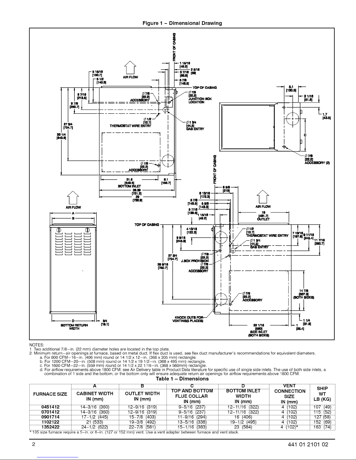
Figure 1 - Dimensional Drawing
i 1.;o.tt'1:'
27_
1"_-71
='"1 F
[i sl tit
?
L ......
7
I
I
I'
21.6 6.1
BOT._M[s'la.5]
INLET
28,39
['nl.2]
29
['n_
TOPOF_WNG I l l 418/10
P
[1_7]
ST_
[148.S] S_--
57110 [14,t.Sl
[lS'IH1 llVffl _
_ [40.21
/ /,i .=q
I-
_86/8
61_V16--
p7e.Sl
"l I ¢1a/4
[els]-7"1 A
s] L 1/1e
I [51.O] 1
___. [,k_s]
c
_-- _7/11
[=21=]
ACC_
t 1
[_vz.ojm_4] /
/ t" &BOXPROVISION
1
147/8
la_.a]
I
(nOTH=,DES)
I
t, .......... __4
--D_ _ _V4
BOTrOM RE11JRN [11kl]
WIDTH
NOTES:
1. Two additional 7/8-in. (22 mm) diameter holes are located in the top plate.
2. Minimum return-air openings at furnace, based on metal duct. If flex duct is used, see flex duct manufacturer's recommendations for equivalent diameters.
a. For 800 CFM-16-in. (406 mm) round or 14 1/2 x 12-in. (368 x 305 mm) rectangle.
b. For 1200 CFM-20-in. (508 mm) round or 14 1/2 x 19 1/2-in. (368 x 495 mm) rectangle.
c. For 1600 CFM-22-in. (559 mm) round or 14 1/2 x 22 1/16-in. (368 x 560mm) rectangle.
d. For airflow requirements above 1800 CFM, see Air Delivery table in Product Data literature for specific use of single side inlets. The use of both side inlets, a
combination of 1 side and the bottom, or the bottom only will ensure adequate return air openings for airflow requirements above 1800 CFM.
VEHTING(6PLACE8)
[511O1
81DEINLET
(BOTHSlDF.m
Table 1 - Dimensions
A
FURNACE SIZE
0451412
0701412
0901714
1102122
1352422
135size furnace require a 5-in. or 6-in. (127 or 152mm) vent. Use a vent adapter between furnace and vent stack.
CABINET WIDTH
IN (mm)
14-3/16 (360)
14-3/16 (360)
17-1/2 (445)
21 (533)
24-1/2 (622)
OUTLET WIDTH
IN (rnm)
12-9/16 (319)
12-9/16 (319)
15-7/8 (403)
19-3/8 (492)
22-7/8 (581)
TOP AND BOTTOM
C
FLUE COLLAR
IN (mm)
9-5/16 (237)
9-5/16 (237)
11-9/16 (294)
13-5/16 (338)
15-1/16 (383)
D
BOTTOM INLET
WIDTH
IN (mm)
12-11/16 (322)
12-11/16 (322)
16 (406)
19-1/2 (495)
23 (584)
_A
1 [_1._]
p_4]
VENT
CONNECTION
SIZE
IN (mm)
4 (102)
4 (102)
4 (102)
4 (102)
4 (102)*
L11/4
SHIP
WT
LB (KG)
107 (49)
115 (52)
127(58)
152 (69)
163 (74)
2
441 01 2101 02
Page 3
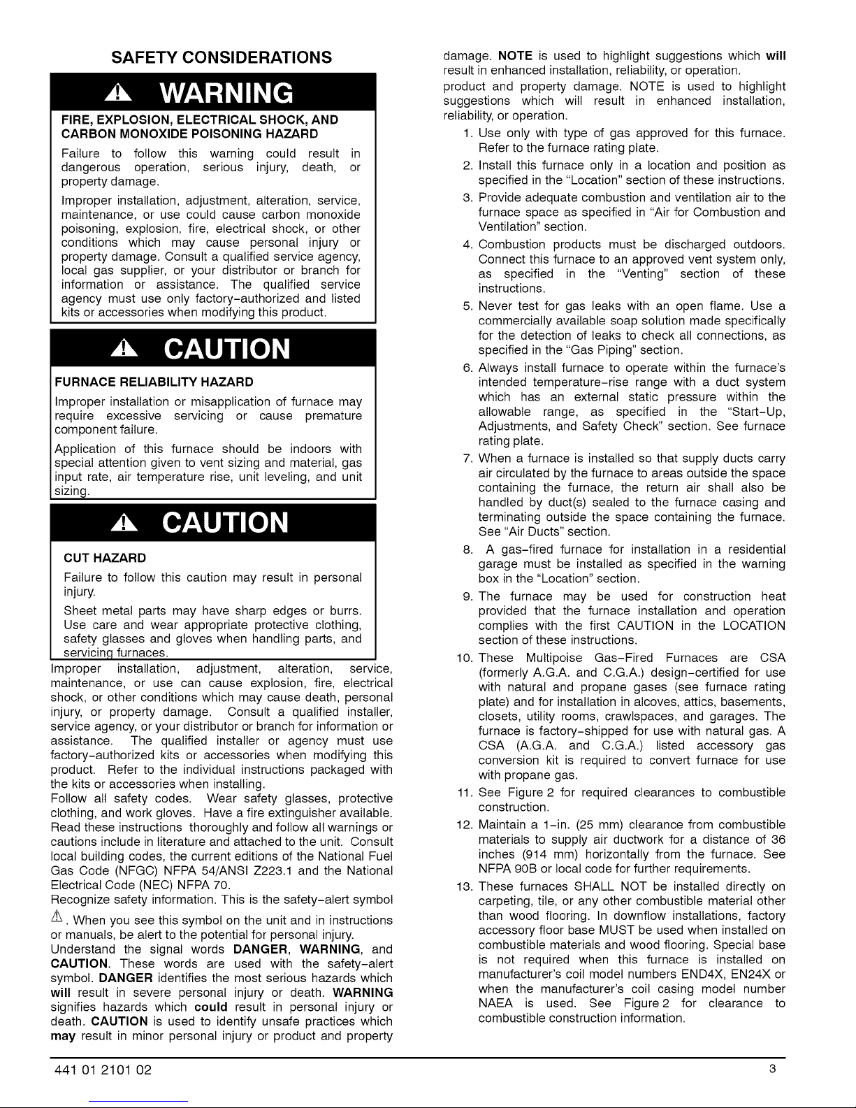
SAFETY CONSIDERATIONS
FIRE, EXPLOSION, ELECTRICAL SHOCK, AND
CARBON MONOXIDE POISONING HAZARD
Failure to follow this warning could result in
dangerous operation, serious injury, death, or
property damage.
Improper installation, adjustment, alteration, service,
maintenance, or use could cause carbon monoxide
poisoning, explosion, fire, electrical shock, or other
conditions which may cause personal injury or
property damage. Consult a qualified service agency,
local gas supplier, or your distributor or branch for
information or assistance. The qualified service
agency must use only factory-authorized and listed
kits or accessories when modifying this product.
FURNACE RELIABILITY HAZARD
Improper installation or misapplication of furnace may
require excessive servicing or cause premature
component failure.
Application of this furnace should be indoors with
special attention given to vent sizing and material, gas
input rate, air temperature rise, unit leveling, and unit
sizing.
CUT HAZARD
Failure to follow this caution may result in personal
injury.
Sheet metal parts may have sharp edges or burrs.
Use care and wear appropriate protective clothing,
safety glasses and gloves when handling parts, and
servicin,q furnaces.
Improper installation, adjustment, alteration, service,
maintenance, or use can cause explosion, fire, electrical
shock, or other conditions which may cause death, personal
injury, or property damage. Consult a qualified installer,
service agency, or your distributor or branch for information or
assistance. The qualified installer or agency must use
factory-authorized kits or accessories when modifying this
product. Refer to the individual instructions packaged with
the kits or accessories when installing.
Follow all safety codes. Wear safety glasses, protective
clothing, and work gloves. Have a fire extinguisher available.
Read these instructions thoroughly and follow all warnings or
cautions include in literature and attached to the unit. Consult
local building codes, the current editions of the National Fuel
Gas Code (NFGC) NFPA 54/ANSI Z223.1 and the National
Electrical Code (NEC) NFPA 70.
Recognize safety information. This is the safety-alert symbol
/_. When you see this symbol on the unit and in instructions
or manuals, be alert to the potential for personal injury.
Understand the signal words DANGER, WARNING, and
CAUTION. These words are used with the safety-alert
symbol. DANGER identifies the most serious hazards which
will result in severe personal injury or death. WARNING
signifies hazards which could result in personal injury or
death. CAUTION is used to identify unsafe practices which
may result in minor personal injury or product and property
damage. NOTE is used to highlight suggestions which will
result in enhanced installation, reliability, or operation.
product and property damage. NOTE is used to highlight
suggestions which will result in enhanced installation,
reliability, or operation.
1. Use only with type of gas approved for this furnace.
Refer to the furnace rating plate.
2. Install this furnace only in a location and position as
specified in the "Location" section of these instructions.
3. Provide adequate combustion and ventilation air to the
furnace space as specified in "Air for Combustion and
Ventilation" section.
4. Combustion products must be discharged outdoors.
Connect this furnace to an approved vent system only,
as specified in the "Venting" section of these
instructions.
5. Never test for gas leaks with an open flame. Use a
commercially available soap solution made specifically
for the detection of leaks to check all connections, as
specified in the "Gas Piping" section.
6. Always install furnace to operate within the furnace's
intended temperature-rise range with a duct system
which has an external static pressure within the
allowable range, as specified in the "Start-Up,
Adjustments, and Safety Check" section. See furnace
rating plate.
7. When a furnace is installed so that supply ducts carry
air circulated by the furnace to areas outside the space
containing the furnace, the return air shall also be
handled by duct(s) sealed to the furnace casing and
terminating outside the space containing the furnace.
See "Air Ducts" section.
8. A gas-fired furnace for installation in a residential
garage must be installed as specified in the warning
box in the "Location" section.
9. The furnace may be used for construction heat
provided that the furnace installation and operation
complies with the first CAUTION in the LOCATION
section of these instructions.
10. These Multipoise Gas-Fired Furnaces are CSA
(formerly A.G.A. and C.G.A.) design-certified for use
with natural and propane gases (see furnace rating
plate) and for installation in alcoves, attics, basements,
closets, utility rooms, crawlspaces, and garages. The
furnace is factory-shipped for use with natural gas. A
CSA (A.G.A. and C.G.A.) listed accessory gas
conversion kit is required to convert furnace for use
with propane gas.
11. See Figure 2 for required clearances to combustible
construction.
12. Maintain a 1-in. (25 mm) clearance from combustible
materials to supply air ductwork for a distance of 36
inches (914 mm) horizontally from the furnace. See
NFPA 90B or local code for further requirements.
13. These furnaces SHALL NOT be installed directly on
carpeting, tile, or any other combustible material other
than wood flooring. In downflow installations, factory
accessory floor base MUST be used when installed on
combustible materials and wood flooring. Special base
is not required when this furnace is installed on
manufacturer's coil model numbers END4X, EN24X or
when the manufacturer's coil casing model number
NAEA is used. See Figure2 for clearance to
combustible construction information.
441 01 2101 02 3
Page 4
INTRODUCTION
F8MTL & G8MTL 4-way multipoise Category I fan-assisted
furnace is CSA (formerly A.G.A. and C.G.A.) design-certified.
A Category I fan-assisted furnace is an appliance equipped
with an integral mechanical means to either draw or force
products of combustion through the combustion chamber
and/or heat exchanger. The furnace is factory-shipped for
use with natural gas. This furnace is not approved for
installation in mobile homes, recreational vehicles, or
outdoors.
These furnaces shall not be installed directly on carpeting,
tile, or any other combustible material other than wood
flooring. For downflow installations, a factory accessory floor
base must be used when installed on combustible materials
and wood flooring. This special base is not required when this
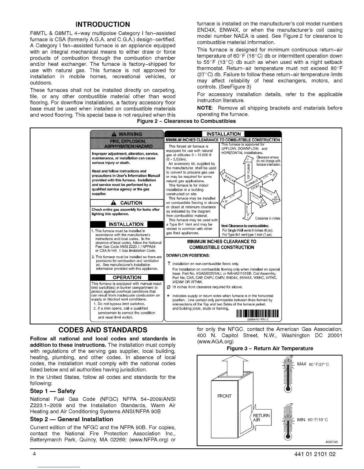
Figure 2 - Clearances to Combustibles
furnace is installed on the manufacturer's coil model numbers
END4X, ENW4X, or when the manufacturer's coil casing
model number NAEA is used. See Figure 2 for clearance to
combustible material information.
This furnace is designed for minimum continuous return-air
temperature of 60°F (16°O) db or intermittent operation down
to 55_'F (13°O) db such as when used with a night setback
thermostat. Return-air temperature must not exceed 80°F
(27°0) db. Failure to follow these return-air temperature limits
may affect reliability of heat exchangers, motors, and
controls. (SeeFigure 3)
For accessory installation details, refer to the applicable
instruction literature.
NOTE: Remove all shipping brackets and materials before
operating the furnace.
Improper adjustment, alteration, service,
maintenance, or installation can cause
serious injury or death,
Read and follow instructions and
precautions in User's Information Manual
provided with this furnace. Installation
and service must be performed by a
qualified service agency or the gas
supplier.
_k. CAUTION
Check entire gas assembly for leaks after
lighting this appliance,
I INSTALLATION
1. This furnace must be installed in
accordance with the manufacturer's
instructions and local codes. In the
absence of local codes, follow the National
Fuel Gas Code ANSI Z223.1 / NFPA54
or CSA B-149. 1 Gas Installation Code.
2. This furnace must be installed so there are
provisions for combustion and ventilation
air. See manufacturer's installation
information provided with this appliance.
I OPERATION I
This furnace is equipped with manual reset
limit switch(es) in burner compartment to
protect against overheat conditions that
can result from inadequate combustion air
supply or blocked vent conditions.
1. Do not bypass limit switches.
2. If a limit opens, call a quallified
serviceman to correct the condition
and reset limit switch.
MINIMUM INCHES CLEARANCE TO COMBUSTIBLE CONSTRUCTION
I INSTALLATION
This forced air furnace is This furnace is approved for
equipped for use with natural UPFLOW, DOWNFLOW, and
gas at altitudes 0 - 10,000 ft Clearancearrows
(O - 3,050m), do not changewith
An accessory kit, supplied by furnaceorientation,
the manufacturer, shall be used
to convert to propane gas use
or may be required for some
natural gas applications,
This furnace is for indoor
installation in a building
constructed on site.
This furnace may be installed
on combustible flooring in alcove
or closet at minimum clearance
as indicated by the diagram
from combustible material.
This furnace may be used with Clearancein inches
a Type B-1 Vent and may be Vent Clearance to combustibles:
vented in common with other For SingleWallvents 6 inches (6 pc).
gas fired appliances. ForType B-1 vent type 1 inch (1 pc).
MINIMUM INCHES CLEARANCE TO
COMBUSTIBLE CONSTRUCTION
DOWNFLOW POSITIONS:
1" Installation on non-combustible floors only.
For Installation on combustible flooring only when installed on special
base, Part No. KGASB0201ALL or NAHA01101SB, Coil Assembly,
Part No. CAR, CAP, CNPV, CNRV, END4X, ENW4X, WENC, WTNC,
WENW OR WTNW.
18 inches front clearance required for alcove.
"k Indicates supply or return sides when furnace is in the horizontal
position. Line contact only permissible between lines formed by
intersections of the Top and two Sides of the furnace jacket,
and building joists, studs or framing.
HORIZONTAL installations.
CODES AND STANDARDS
Follow all national and local codes and standards in
addition to these instructions. The installation must comply
with regulations of the serving gas supplier, local building,
heating, plumbing, and other codes. In absence of local
codes, the installation must comply with the national codes
listed below and all authorities having jurisdiction.
In the United States, follow all codes and standards for the
following:
Step 1 m Safety
National Fuel Gas Code (NFGC) NFPA 54-2009/ANSI
Z223.1-2009 and the Installation Standards, Warm Air
Heating and Air Conditioning Systems ANSI/NFPA 90B
Step 2 m General Installation
Current edition of the NFGC and the NFPA 90B. For copies,
contact the National Fire Protection Association Inc.,
Batterymarch Park, Quincy, MA 02269; (www.NFPA.org) or
4 441 01 2101 02
for only the NFGC, contact the American Gas Association,
400 N. Capitol Street, N.W., Washington DC 20001
(www.AGA.org)
Figure 3 - Return Air Temperature
- - MAX 80 °F/27 °C
FRONT
MIN 60°F/16°0
A06745
Page 5
Step 3 m Combustion and Ventilation Air
Section 9.3 of the NFGC, NFPA 54/ANSI Z223.1-2009 Air
for Combustion and Ventilation
Step 4 m Duct Systems
Air Conditioning Contractors Association (ACCA) Manual D,
Sheet Metal and Air Conditioning Contractors National
Association (SMACNA), or American Society of Heating,
Refrigeration, and Air Conditioning Engineers (ASHRAE)
2001 Fundamentals Handbook Chapter 34 or 2000 HVAC
Systems and Equipment Handbook Chapters 9 and 16.
Step 5 _ Acoustical Lining and Fibrous Glass
Duct
Current edition of SMACNA and NFPA 90B as tested by UL
Standard 181 for Class I Rigid Air Ducts
Step 6 _ Gas Piping and Gas Pipe Pressure
Testing
NFPA 54 / ANSI Z223.1-2009; chapters 5, 6, 7, and 8 and
National Plumbing Codes
Step 7 _ Electrical Connections
National Electrical Code (NEC) ANSI/NFPA 70-2008
Step 8 _ Venting
NFGC; NFPA 54/ANSI Z223.1-2009 chapters 12 and 13
ELECTROSTATIC DISCHARGE (ESD)
PRECAUTIONS PROCEDURE
1. Disconnect all power to the furnace. Multiple
disconnects may be required. DO NOT TOUCH THE
CONTROL OR ANY WIRE CONNECTED TO THE
CONTROL PRIOR TO DISCHARGING YOUR BODY'S
ELECTROSTATIC CHARGE TO GROUND.
2. Firmly touch the clean, unpainted, metal surface of the
furnace chassis which is close to the control. Tools
held in a person's hand during grounding will be
satisfactorily discharged.
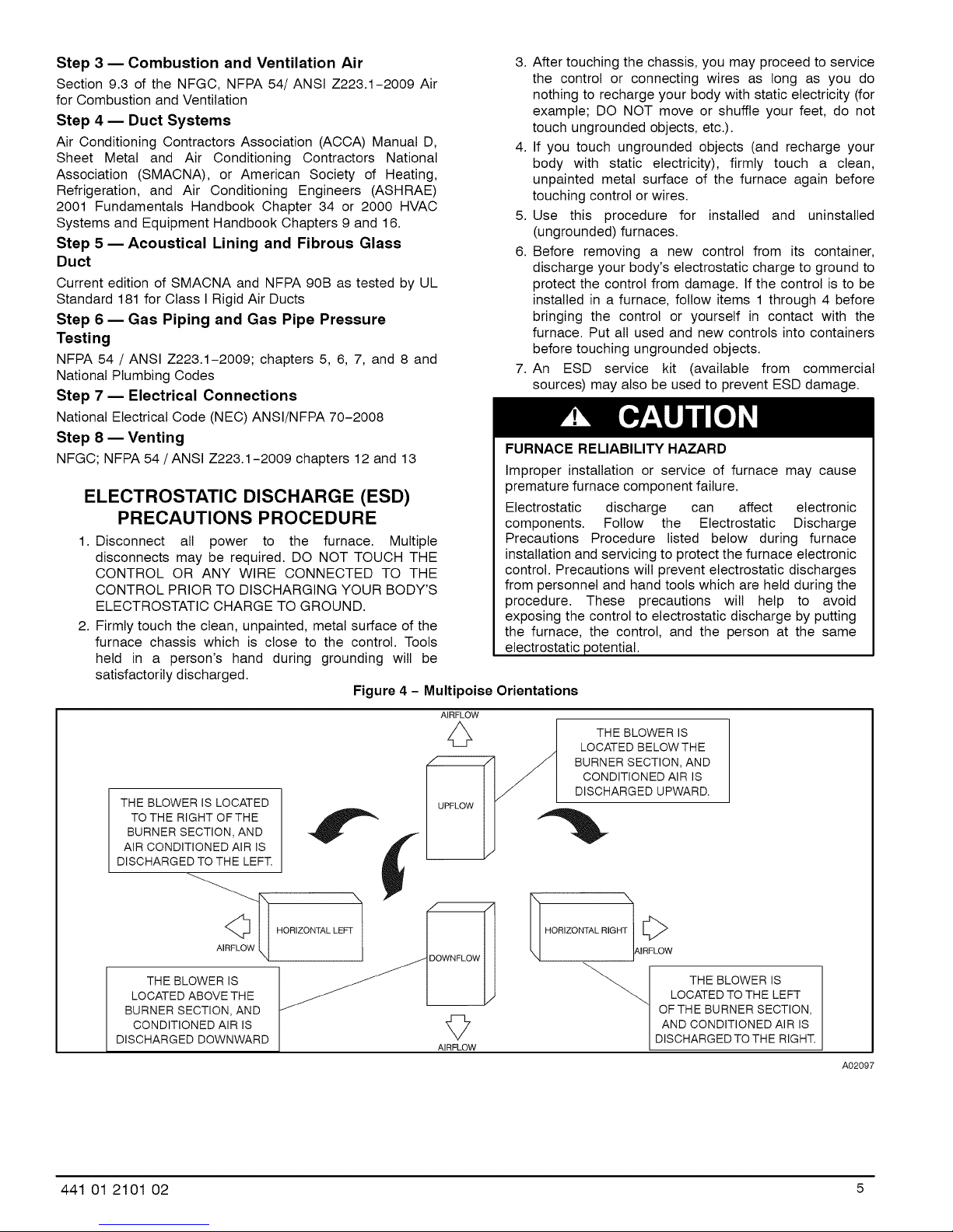
Figure 4 - Multipoise Orientations
THE BLOWER IS LOCATED
TO THE RIGHT OF THE
BURNER SECTION, AND
AIR CONDITIONED AIR IS
DISCHARGED TO THE LEFT.
3. After touching the chassis, you may proceed to service
the control or connecting wires as long as you do
nothing to recharge your body with static electricity (for
example; DO NOT move or shuffle your feet, do not
touch ungrounded objects, etc.).
4. If you touch ungrounded objects (and recharge your
body with static electricity), firmly touch a clean,
unpainted metal surface of the furnace again before
touching control or wires.
5. Use this procedure for installed and uninstatled
(ungrounded) furnaces.
6. Before removing a new control from its container,
discharge your body's electrostatic charge to ground to
protect the control from damage. If the control is to be
installed in a furnace, follow items 1 through 4 before
bringing the control or yourself in contact with the
furnace. Put all used and new controls into containers
before touching ungrounded objects.
7. An ESD service kit (available from commercial
sources) may also be used to prevent ESD damage.
FURNACE RELIABILITY HAZARD
Improper installation or service of furnace may cause
premature furnace component failure.
Electrostatic discharge can affect electronic
components. Follow the Electrostatic Discharge
Precautions Procedure listed below during furnace
installation and servicing to protect the furnace electronic
control. Precautions will prevent electrostatic discharges
from personnel and hand tools which are held during the
procedure. These precautions will help to avoid
exposing the control to electrostatic discharge by putting
the furnace, the control, and the person at the same
electrostatic potential.
AIRFLOW
THE BLOWER IS
LOCATED BELOW THE
BURNER SECTION, AND
CONDITIONED AIR IS
DISCHARGED UPWARD.
THE BLOWER IS
LOCATED ABOVE TH E
BURNER SECTION, AND
CONDITIONED AIR IS
DISCHARGED DOWNWARD
441 01 2101 O2 5
\
HORIZONTAL RIGHT [_>
AIRFLOW
LOCATED TO THE LEFT
OF THE BURNER SECTION,
AND CONDITIONED AIR IS
THE BLOWER IS
DISCHARGED TO THE RIGHT.
A02097
Page 6
LOCATION
GENERAL
This multipoise furnace is shipped in packaged configuration.
Some assembly and modifications are required when used in
any of the four applications shown in Figure 4.
NOTE: For high-attitude installations, the high-altitude
conversion kit MUST be installed at or above 5500 ft. (1676
M) above sea level. Obtain high-attitude conversion kit from
your area authorized distributor.
This furnace must:
• be installed so the electrical components are protected from
water.
• not be installed directly on any combustible material other
than wood flooring for upftow applications. Downflow
installations require use of a factory-approved floor base,
coil model numbers END4X, ENW4X, or the manufacturer's
coil casing model number NAEA, when installed on
combustible materials or wood flooring (refer to SAFETY
CONSIDERATIONS).
• be located close to the chimney or vent and attached to an
air distribution system. Refer to Air Ducts section.
• be provided ample space for servicing and cleaning. Always
comply with minimum fire protection clearances shown on
the furnace clearance to combustible construction label.
The following types of furnace installations may require
OUTDOOR AIR for combustion due to chemical exposures:
• Commercial buildings
• Buildings with indoor pools
• Laundry rooms
• Hobby or craft rooms, and
• Chemical storage areas
• De-icing salts or chemicals
• Carbon tetrachloride
• Halogen type refrigerants
• Cleaning solvents (such as perchloroethylene)
• Printing inks, paint removers, varnishes, etc.
• Hydrochloric acid
• Cements and glues
• Antistatic fabric softeners for clothes dryers
• Masonry acid washing materials
All fuel-burning equipment must be supplied with air for fuel
combustion. Sufficient air must be provided to avoid negative
pressure in the equipment room or space. A positive seal
must be made between the furnace cabinet and the
return-air duct to prevent pulling air from the burner area
and from draft safeguard opening.
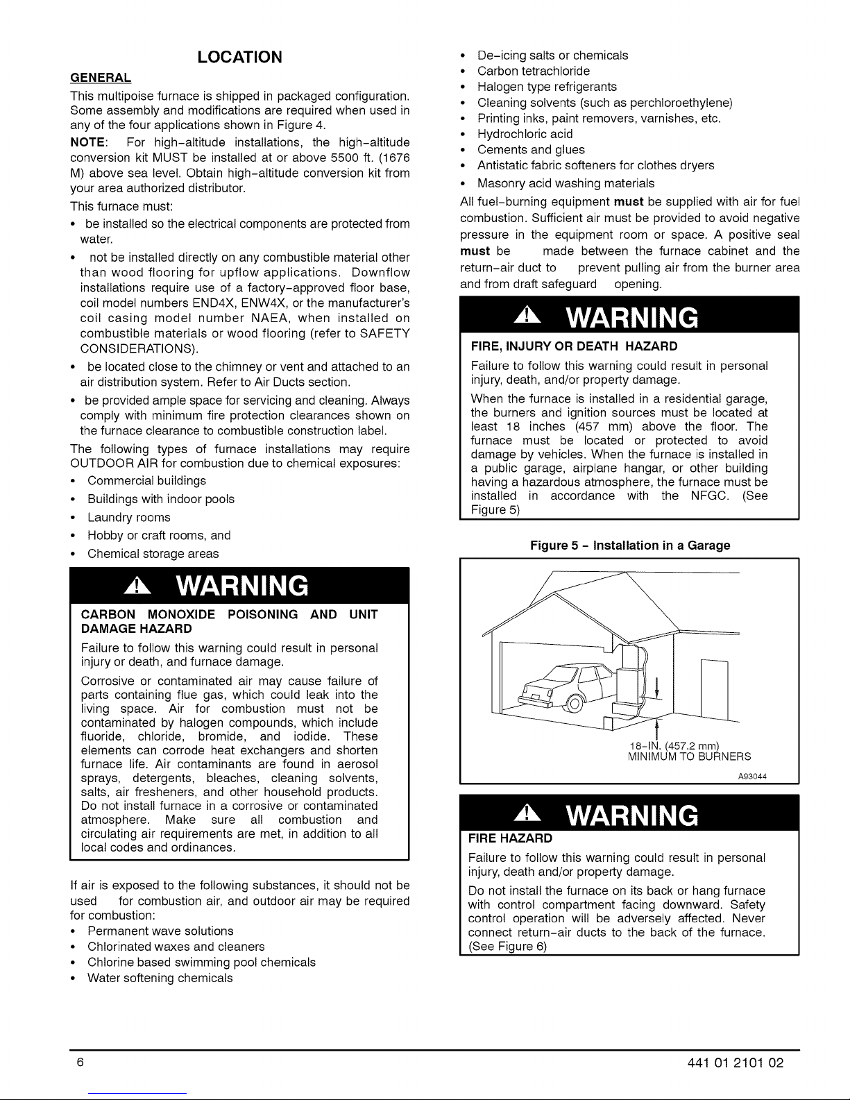
FIRE, INJURY OR DEATH HAZARD
Failure to follow this warning could result in personal
injury, death, and/or property damage.
When the furnace is installed in a residential garage,
the burners and ignition sources must be located at
least 18 inches (457 mm) above the floor. The
furnace must be located or protected to avoid
damage by vehicles. When the furnace is installed in
a public garage, airplane hangar, or other building
having a hazardous atmosphere, the furnace must be
installed in accordance with the NFGC. (See
Figure 5)
Figure 5 - Installation in a Garage
CARBON MONOXIDE POISONING AND UNIT
DAMAGE HAZARD
Failure to follow this warning could result in personal
injury or death, and furnace damage.
Corrosive or contaminated air may cause failure of
parts containing flue gas, which could leak into the
living space. Air for combustion must not be
contaminated by halogen compounds, which include
fluoride, chloride, bromide, and iodide. These
elements can corrode heat exchangers and shorten
furnace life. Air contaminants are found in aerosol
sprays, detergents, bleaches, cleaning solvents,
salts, air fresheners, and other household products.
Do not install furnace in a corrosive or contaminated
atmosphere. Make sure all combustion and
circulating air requirements are met, in addition to all
local codes and ordinances.
If air is exposed to the following substances, it should not be
used for combustion air, and outdoor air may be required
for combustion:
• Permanent wave solutions
• Chlorinated waxes and cleaners
• Chlorine based swimming pool chemicals
• Water softening chemicals
18-iN. (457.2 mm)
MINIMUMTO BURNERS
A93044
FIRE HAZARD
Failure to follow this warning could result in personal
injury, death and/or property damage.
Do not install the furnace on its back or hang furnace
with control compartment facing downward. Safety
control operation will be adversely affected. Never
connect return-air ducts to the back of the furnace.
(See Figure 6)
6 441 01 2101 02
Page 7
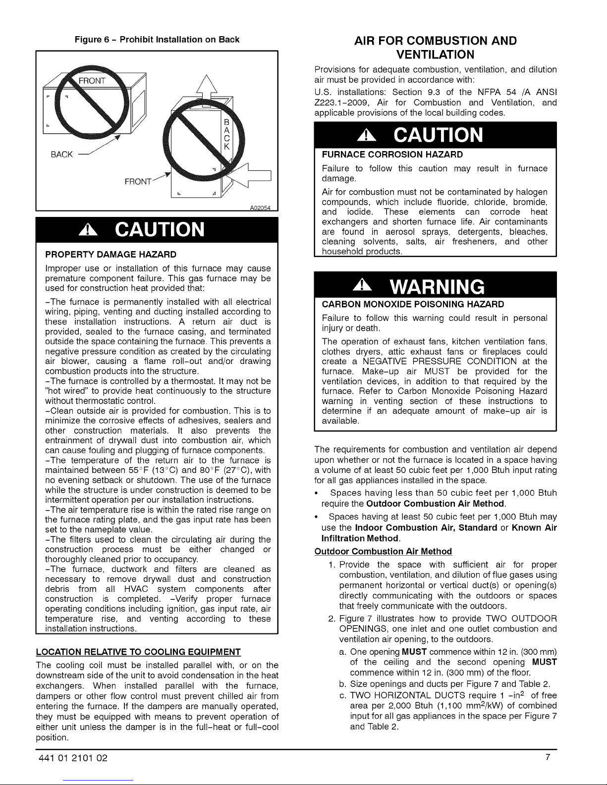
Figure 6 - Prohibit Installation on Back
AIR FOR COMBUSTION AND
VENTILATION
Provisions for adequate combustion, ventilation, and dilution
air must be provided in accordance with:
U.S. installations: Section 9.3 of the NFPA 54 /A ANSI
Z223.1-2009, Air for Combustion and Ventilation, and
applicable provisions of the local building codes.
BACK J
A02054
PROPERTY DAMAGE HAZARD
Improper use or installation of this furnace may cause
premature component failure. This gas furnace may be
used for construction heat provided that:
-The furnace is permanently installed with all electrical
wiring, piping, venting and ducting installed according to
these installation instructions. A return air duct is
provided, sealed to the furnace casing, and terminated
outside the space containing the furnace. This prevents a
negative pressure condition as created by the circulating
air blower, causing a flame roll-out and/or drawing
combustion products into the structure.
-The furnace is controlled by a thermostat. It may not be
"hot wired" to provide heat continuously to the structure
without thermostatic control.
-Clean outside air is provided for combustion. This is to
minimize the corrosive effects of adhesives, sealers and
other construction materials. It also prevents the
entrainment of drywall dust into combustion air, which
can cause fouling and plugging of furnace components.
-The temperature of the return air to the furnace is
maintained between 55°F (13°C) and 80°F (27°C), with
no evening setback or shutdown. The use of the furnace
while the structure is under construction is deemed to be
intermittent operation per our installation instructions.
-The air temperature rise is within the rated rise range on
the furnace rating plate, and the gas input rate has been
set to the nameplate value.
-The filters used to clean the circulating air during the
construction process must be either changed or
thoroughly cleaned prior to occupancy.
-The furnace, ductwork and filters are cleaned as
necessary to remove drywall dust and construction
debris from all HVAC system components after
construction is completed. -Verify proper furnace
operating conditions including ignition, gas input rate, air
temperature rise, and venting according to these
installation instructions.
LOCATION RELATIVE TO COOLING EQUIPMENT
The cooling coil must be installed parallel with, or on the
downstream side of the unit to avoid condensation in the heat
exchangers. When installed parallel with the furnace,
dampers or other flow control must prevent chilled air from
entering the furnace. If the dampers are manually operated,
they must be equipped with means to prevent operation of
either unit unless the damper is in the full-heat or full-cool
position.
FURNACE CORROSION HAZARD
Failure to follow this caution may result in furnace
damage.
Air for combustion must not be contaminated by halogen
compounds, which include fluoride, chloride, bromide,
and iodide. These elements can corrode heat
exchangers and shorten furnace life. Air contaminants
are found in aerosol sprays, detergents, bleaches,
cleaning solvents, salts, air fresheners, and other
household products.
CARBON MONOXIDE POISONING HAZARD
Failure to follow this warning could result in personal
injury or death.
The operation of exhaust fans, kitchen ventilation fans,
clothes dryers, attic exhaust fans or fireplaces could
create a NEGATIVE PRESSURE CONDITION at the
furnace. Make-up air MUST be provided for the
ventilation devices, in addition to that required by the
furnace. Refer to Carbon Monoxide Poisoning Hazard
warning in venting section of these instructions to
determine if an adequate amount of make-up air is
available.
The requirements for combustion and ventilation air depend
upon whether or not the furnace is located in a space having
a volume of at least 50 cubic feet per 1,000 Btuh input rating
for atl gas appliances installed in the space.
• Spaces having less than 50 cubic feet per 1,000 Btuh
require the Outdoor Combustion Air Method.
• Spaces having at least 50 cubic feet per 1,000 Btuh may
use the Indoor Combustion Air, Standard or Known Air
Infiltration Method.
Outdoor Combustion Air Method
1. Provide the space with sufficient air for proper
combustion, ventilation, and dilution of flue gases using
permanent horizontal or vertical duct(s) or opening(s)
directly communicating with the outdoors or spaces
that freely communicate with the outdoors.
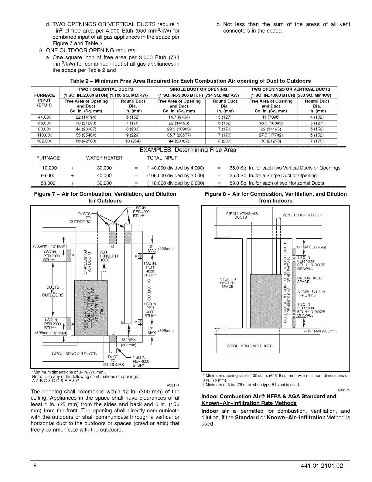
2. Figure 7 illustrates how to provide TWO OUTDOOR
OPENINGS, one inlet and one outlet combustion and
ventilation air opening, to the outdoors.
a. One opening MUST commence within 12 in. (300 mm)
of the ceiling and the second opening MUST
commence within 12 in. (300 mm) of the floor.
b. Size openings and ducts per Figure 7 and Table 2.
c. TWO HORIZONTAL DUCTS require 1 -in 2 of free
area per 2,000 Btuh (1,100 mm2/kW) of combined
input for all gas appliances in the space per Figure 7
and Table 2.
441 01 2101 O2 7
Page 8
d. TWO OPENINGS OR VERTICAL DUCTS require 1
-in 2 of free area per 4,000 Btuh (550 mm2/kW) for
b. Not less than the sum of the areas of all
connectors in the space.
combined input of all gas appliances in the space per
Figure 7 and Table 2
3. ONE OUTDOOR OPENING requires:
a. One square inch of free area per 3,000 Btuh (734
mm2/kW) for combined input of all gas appliances in
the space per Table 2 and
Table 2 - Minimum Free Area Required for Each Combustion Air opening of Duct to Outdoors
TWO HORIZONTAL DUCTS SINGLE DUCT OR OPENING TWO OPENINGS OR VERTICAL DUCTS
FURNACE (1 SQ. IN./2,O00 BTUH) (1,100 SQ. MM/KW) (1 SQ. IN./3,O00 BTUH) (734 SQ. MM/KW) (1 SQ. IN./4,O00 BTUH) (550 SQ. MM/KW)
INPUT Free Area of Opening Round Duct Free Area of Opening Round Duct Free Area of Opening Round Duct
(BTUH) and Duct Dia. and Duct Dia. and Duct Dia.
Sq. In. (Sq. mm) In. (mm) Sq. In. (Sq. mm) In. (mm) Sq. In. (Sq. mm) In. (mm)
44,000 22 (14194) 6 (152) 14.7 (9484) 5 (127) 11 (7096) 4 (102)
66,000 33 (21290) 7 (178) 22 (14193) 6 (152) 16.5 (10645) 5 (127)
88,000 44 (28387) 8 (203) 29.3 (18903) 7 (178) 22 (14193) 6 (152)
110,000 55 (35484) 9 (229) 36.7 (23677) 7 (178) 27.5 (17742) 6 (152)
132,000 66 (42580) 10 (254) 44 (28387) 8 (203) 33 (21290) 7 (178)
EXAMPLES: Determining Free Area
FURNACE WATERHEATER TOTAL INPUT
110,000 + 30,000 = (140,000 divided by 4,000) = 35.0 Sq. In. for each two Vertical Ducts or Openings
66,000 + 40,000 = (106,000 divided by 3,000) = 35.3 Sq. In. for a Single Duct or Opening
vent
Figure 7 - Air for Combustion, Ventilation, and Dilution
for Outdoors
1 SQ IN.
SQ IN.
PER
400O
BTUH*
cO
rr
8
GI
o
1 SQ IN.
PER
4OOO
BTUH*
12" (305mm)
MAX
(305mm) 12" MAX
1 SQIN. A
PER 2000
BTUH*
DUCTS
TO
OUTDOORS
1 SQ IN.
PER 2000
BTUH*
(305mm) 12" MAX
DUCT,' PER 4000
TO BTUH*
OUTDOORS
D 12_X (305mm)
VENT
THROUGH
ROOF
i
I
CIRCULATING AIR DUCTS
TO PER 4O00
OUTDOORS BTUH*
*Minimum dimensions of 3-in. (76 mm).
Note: Use any of the following combinations of openings:
A&BC&DD&EF&G
The opening shall commence within 12 in. (300 mm) of the
ceiling. Appliances in the space shall have clearances of at
least 1 in. (25 mm) from the sides and back and 6 in. (150
mm) from the front. The opening shall directly communicate
with the outdoors or shall communicate through a vertical or
horizontal duct to the outdoors or spaces (crawl or attic) that
freely communicate with the outdoors.
1 SQ IN.
A03174
Figure 8 - Air for Combustion, Ventilation, and Dilution
from Indoors
DUCTS
CIRCULATING AiR !
I I I I I
I I I I I
I I I I I
INTERIOR
HEATED
SPACE
i i
CIRCULATING AIR DUCTS
* Minimum opening size is 100 sq in. (64516 sq. mm) with minimum dimensions of
3 in. (76 ram)
1 Minimum of 3 in. (76 mm) when type-B1 vent is used.
VENT THROUGH ROOF
12" AX(305mm)
o *
_ 1 SQ IN.
• PER 1000
BTUH* iN DOOR
ORWALL
UNCONFINED
SPACE
6" MIN (152mm)
(FRONT)0
1 SQ iN.
PER 1000
_: BTUH* iN DOOR
_-----OR WALL
12" MAX (305mm)
A03175
Indoor Combustion Air@ NFPA & AGA Standard and
Known-Air-Infiltration Rate Methods
Indoor air is permitted for combustion, ventilation, and
dilution, if the Standard or Known-Air-Infiltration Method is
used.
8 441 01 2101 02
Page 9
CARBONMONOXIDE POISONING HAZARD
Failure to follow this warning could result in death
and/or personal injury.
Many homes require air to be supplied from outdoors
for furnace combustion, ventilation, and dilution of flue
gases. The furnace combustion air supply must be
provided in accordance with this instruction manual.
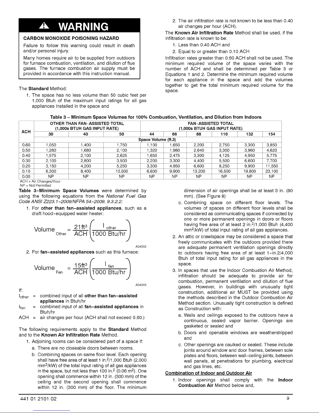
The Standard Method:
1. The space has no less volume than 50 cubic feet per
1,000 Btuh of the maximum input ratings for all gas
appliances installed in the space and
Table 3 - Minimum Space Volumes for 100% Combustion, Ventilation, and Dilution from Indoors
OTHER THAN FAN-ASSISTED TOTAL FAN-ASSISTED TOTAL
ACH
0.60 1,050
0.50 1,260
0.40 1,575
0.30 2,100
0.20 3,150
0.10 6,300
0.00 NP
ACH =Air Changes/Hour
NP = NotPermitted
Table 3-Minimum Space Volumes were determined by
using the following equations from the National Fuel Gas
Code ANSI Z223.1-2009/NFPA 54-2009, 9.3.2.2:
1. For other than fan-assisted appliances, such as a
draft hood-equipped water heater:
Volume _ 21ft3 (f= [other ='_
2. For fan-assisted appliances such as this furnace:
Volume
If:
Iother
= combined input of all other than fan-assisted
Ifan
= combined input of all fan-assisted appliances in
ACH
= air changes per hour (ACH shall not exceed 0.60.)
The following requirements apply to the Standard Method
and to the Known Air Infiltration Rate Method.
1. Adjoining rooms can be considered part of a space if:
a. There are no closeable doors between rooms.
b. Combining spaces on same floor level. Each opening
shall have free area of at least 1 in.2/1,000 Btuh (2,000
mm2/kW) of the total input rating of all gas appliances
in the space, but not less than 100 in.2 (0.06 m2). One
opening shall commence within 12 in. (300 mm) of the
ceiling and the second opening shall commence
within 12 in. (300 mm) of the floor. The minimum
(1,000s BTUH GAS INPUT RATE) (1,000s BTUH GAS INPUT RATE)
30 40 50 44 66 88 110 132 154
S _ace Volume (ft.3)
1,400 1,750 1,100 1,650 2,200 2,750 3,300 3,850
1,680 2,100 1,320 1,980 2,640 3,300 3,960 4,620
2,100 2,625 1,650 2,475 3,300 4,125 4,950 5,775
2,800 3,500 2,200 3,300 4,400 5,500 6,600 7,700
4,200 5,250 3,300 4,950 6,600 8,250 9,900 11,550
8,400 10,500 6,600 9,900 13,200 16,500 19,800 23,100
NP NP NP NP NP NP NP NP
Other ACH _000 Btu/hrJ
A04002
FaR
ACH 000 Btu/hrJ
A04003
appliances in Btuh/hr
Btuh/hr
2. The air infiltrationrate is not known to be less than 0.40
air changes per hour (ACH).
The Known Air Infiltration Rate Method shall be used, if the
infiltration rate is known to be:
1. Less than 0.40 ACH and
2. Equal to or greater than 0.10 ACH
Infiltration rates greater than 0.60 ACH shall not be used. The
minimum required volume of the space varies with the
number of ACH and shall be determined per Table 3 or
Equations 1 and 2. Determine the minimum required volume
for each appliance in the space and add the volumes
together to get the total minimum required volume for the
space.
dimension of air openings shall be at least 3 in. (80
mm). (See Figure 8)
c. Combining space on different floor levels. The
volumes of spaces on different floor levels shall be
considered as communicating spaces if connected by
one or more permanent openings in doors or floors
having free area of at least 2 in.2/1,000 Btuh (4,400
mm2/kW) of total input rating of all gas appliances.
2.
An attic or crawlspace may be considered a space that
freely communicates with the outdoors provided there
are adequate permanent ventilation openings directly
to outdoors having free area of at least 1-in.2/4,000
Btuh of total input rating for all gas appliances in the
space.
3.
In spaces that use the Indoor Combustion Air Method,
infiltration should be adequate to provide air for
combustion, permanent ventilation and dilution of flue
gases. However, in buildings with unusually tight
construction, additional air MUST be provided using
the methods described in the Outdoor Combustion Air
Method section. Unusually tight construction is defined
as Construction with:
a. Walls and ceilings exposed to the outdoors have a
continuous, sealed vapor barrier. Openings are
gasketed or sealed and
b. Doors and openable windows are weatherstripped
and
c. Other openings are caulked or sealed. These include
joints around window and door frames, between sole
plates and floors, between wall-ceiling joints, between
wall panels, at penetrations for plumbing, electrical
and gas lines, etc.
Combination of Indoor and Outdoor Air
1. Indoor openings shall comply with
the Indoor
Combustion Air Method below and,
441 01 2101 02 9
Page 10

2.Outdooropeningsshallbelocatedasrequiredinthe
Outdoor CombustionAir Methodmentioned
previouslyand,
3.Outdooropeningsshallbesizedasfollows:
a.CalculatetheRatioofallIndoorSpacevolumedivided
by requiredvolumefor IndoorCombustionAir
Methodbelow.
b.OutdooropeningsizereductionFactoris1minusthe
Ratioina.above.
c.MinimumsizeofOutdooropeningsshallbethesize
requiredinOutdoorCombustionAirMethodabove
multipliedby reductionFactorin b. above.The
minimumdimensionofairopeningsshallbenotless
than3in.(80mm).
INSTALLATION
UPFLOW INSTALLATION
Bottom Return Air Inlet
These furnaces are shipped with bottom closure panel
installed in bottom return-air opening. Remove and discard
this panel when bottom return air is used. To remove bottom
closure panel, perform the following:
1. Tilt or raise furnace and remove 2 screws holding
bottom filler panel. (See Figure 9)
2. Rotate bottom filler panel downward to release holding
tabs.
3. Remove bottom closure panel.
4. Reinstall bottom filler panel and screws.
Side Return Air Inlet
These furnaces are shipped with bottom closure panel
installed in bottom return-air opening. This panel MUST be in
place when only side return air is used.
NOTE: Side return-air openings can be used in UPFLOW
and most HORIZONTAL configurations. Do not use side
return-air openings in DOWNFLOW configuration.
Figure 9 - Removing Bottom Closure Panel
o
o
I
BOTTOM
CLOSURE
PANEL
BOTTOM
FILLER PANEL
Levelinq Leqs (If Desired)
In upflow position with side return inlet(s), leveling legs may
be used. (See Figure 10) Install field-supplied, 5/16 x 1-1/2
in. (8 x 38 mm) (max) corrosion-resistant machine bolts,
washers and nuts.
NOTE: Bottom closure must be used when leveling legs are
used. It may be necessary to remove and reinstall bottom
closure panel to install leveling legs. To remove bottom
closure panel, see item 1 in Bottom Return Air Inlet section in
Step 1 above.
To install leveling legs:
1. Position furnace on its back. Locate and drill a hole in
each bottom corner of furnace. (See Figure 10)
2. For each leg, install nut on bolt and then install bolt and
nut in hole. (Install flat washer if desired.)
3. Install another nut on other side of furnace base.
(Install flat washer if desired.)
4. Adjust outside nut to provide desired height, and
tighten inside nut to secure arrangement.
5. Reinstall bottom closure panel if removed.
Figure 10 - Leveling Legs
(Smm)
1
(44ram)
I 3/4"
(44mm)
(Smm)
(Smm)
(44mm) 1 3/4"
(44mm) 1
A89014
DOWNFLOW INSTALLATION
NOTE: For downflow applications, this furnace is approved
for use on combustible flooring when any one of the following
two accessories are used:
• Downflow combustible floor subbase
• Coil model numbers END4X or ENW4X
• Coil casing model number NAEA
1. Determine application being installed from Table 4.
2. Construct hole in floor per Table 4 and Figure 13.
3. Construct plenum to dimensions specified in Table 4
and Figure 13.
4. If downflow subbase is used, install as shown in
Figure 11. If coil model numbers END4X, ENW4X or
coil casing model number NEAE is used, install as
shown in Figure 12.
NOTE: It is recommended that the perforated supply-air duct
flanges be completely folded over or removed from furnace
when installing the furnace on a factory-supplied cased coil
or coil casing. To remove the supply-air duct flange, use wide
duct pliers or hand seamers to bend flange back and forth
until it breaks off. Be careful of sharp edges. (See Figure 14)
10 441 01 2101 02
Page 11
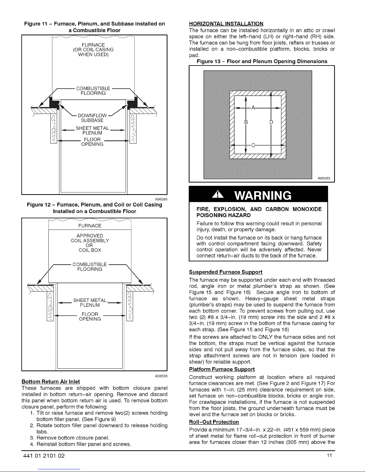
Figure 11 - Furnace, Plenum, and Subbase installed on
a Combustible Floor
FURNACE
(OR COIL CASING
WHEN USED)
COMBUSTIBLE
FLOORING
SUBBASE
SHEET METAL
PLENUM
FLOOR
OPENING
HORIZONTAL INSTALLATION
The furnace can be installed horizontally in an attic or crawl
space on either the left-hand (LH) or right-hand (RH) side.
The furnace can be hung from floor joists, rafters or trusses or
installed on a non-combustible platform, blocks, bricks or
pad.
Figure 13 - Floor and Plenum Opening Dimensions
A96283
A96285
Figure 12 - Furnace, Plenum, and Coil or Coil Casing
Installed on a Combustible Floor
FURNACE
APPROVED
COIL ASSEMBLY
OR
COIL BOX
_ COMBUSTIBLE
FLOORING x
SHEET METAL ====.._
PLENUM
FLOOR
OPENING
/
A08556
Bottom Return Air Inlet
These furnaces are shipped with bottom closure panel
installed in bottom return-air opening. Remove and discard
this panel when bottom return air is used. To remove bottom
closure panel, perform the following:
1. Tilt or raise furnace and remove two(2) screws holding
bottom filler panel. (See Figure 9)
2. Rotate bottom filler panel downward to release holding
tabs.
3. Remove bottom closure panel.
4. Reinstall bottom filler panel and screws.
FIRE, EXPLOSION, AND CARBON MONOXIDE
POISONING HAZARD
Failure to follow this warning could result in personal
injury, death, or property damage.
Do not install the furnace on its back or hang furnace
with control compartment facing downward. Safety
control operation will be adversely affected. Never
connect return-air ducts to the back of the furnace.
Suspended Furnace Support
The furnace may be supported under each end with threaded
rod, angle iron or metal plumber's strap as shown. (See
Figure 15 and Figure 16) Secure angle iron to bottom of
furnace as shown. Heavy-gauge sheet metal straps
(plumber's straps) may be used to suspend the furnace from
each bottom corner. To prevent screws from pulling out, use
two (2) #8 x 3/4-in. (19 mm) screw into the side and 2 #8 x
3/4-in. (19 mm) screw in the bottom of the furnace casing for
each strap. (See Figure 15 and Figure 16)
If the screws are attached to ONLY the furnace sides and not
the bottom, the straps must be vertical against the furnace
sides and not pull away from the furnace sides, so that the
strap attachment screws are not in tension (are loaded in
shear) for reliable support.
Platform Furnace Support
Construct working platform at location where all required
furnace clearances are met. (See Figure 2 and Figure 17) For
furnaces with 1-in. (25 mm) clearance requirement on side,
set furnace on non-combustible blocks, bricks or angle iron.
For crawlspace installations, if the furnace is not suspended
from the floor joists, the ground underneath furnace must be
level and the furnace set on blocks or bricks.
Roll-Out Protection
Provide a minimum 17-3/4-in. x 22-in. (451 x 559 ram) piece
of sheet metal for flame roll-out protection in front of burner
area for furnaces closer than 12 inches (305 mm) above the
441 01 2101 02 11
Page 12
combustibledeckorsuspendedfurnacescloserthan12
inches(305mm)tojoists.ThesheetmetalMUSTextend
underneaththefurnacecasingby1in.(25mm)withthedoor
removed.
Thebottomclosurepanelonfurnacesofwidths17-1/2in.
(445mm)andlargermaybe usedfor flameroll-out
protectionwhenbottomof furnaceis usedfor returnair
connection.SeeFigure17forproperorientationofroll-out
shield.
Bottom Return Air Inlet
These furnaces are shipped with bottom closure panel
installed in bottom return-air opening. Remove and discard
this panel when bottom return air is used. To remove bottom
closure panel, perform the following:
1. Tilt or raise furnace and remove two (2) screws holding
bottom filler panel. (See Figure 9)
2. Rotate bottom filler panel downward to release holding
tabs.
3. Remove bottom closure panel.
4. Reinstall bottom filler panel and screws.
Side Return Air Inlet
These furnaces are shipped with bottom closure panel
installed in bottom return-air opening. This panel MUST be in
place when side return air inlet(s) are used without a bottom
return air inlet.
FURNACE
CASING
WIDTH
14-3/16
(376)
17-1/2
(445)
21
(533)
24-1/2
(622)
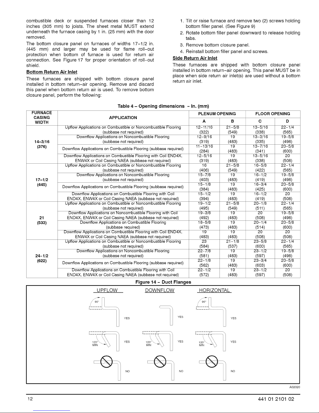
Table 4 - Opening dimensions - In.
APPLICATION
Upflow Applications on Combustible or Noncombustible Flooring
(subbase not required)
Downflow Applications on Noncombustible Flooring
(subbase not required)
Downflow Applications on Combustible Flooring (subbase required)
Downflow Applications on Combustible Flooring with Coil END4X,
ENW4X or Coil Casing NAEA (subbase not required)
Upflow Applications on Combustible or Noncombustible Flooring
(subbase not required)
Downflow Applications on Noncombustible Flooring
(subbase not required)
Downflow Applications on Combustible Flooring (subbase required)
Downflow Applications on Combustible Flooring with Coil
END4X, ENW4X or Coil Casing NAEA (subbase not required)
Upflow Applications on Combustible or Noncombustible Flooring
(subbase not required)
Downflow Applications on Noncombustible Flooring with Coil
END4X, ENW4X or Coil Casing NAEA (subbase not required)
Downflow Applications on Combustible Flooring
(subbase required)
Downflow Applications on Combustible Flooring with Coil END4X,
ENW4X or Coil Casing NAEA (subbase not required)
Upflow Applications on Combustible or Noncombustible Flooring
(subbase not required)
Downflow Applications on Noncombustible Flooring
(subbase not required)
Downflow Applications on Combustible Flooring (subbase required)
Downflow Applications on Combustible Flooring with Coil
END4X, ENW4X or Coil Casing NAEA (subbase not required)
Figure 14 - Duct Flanges
U PFLOW DOWN FLOW
(mm)
PLENUMOPENING
A B
12-11/16 21-5/8
(322) (549)
12-9/16 19
(319) (483)
11-13/16 19
(284) (483)
12-5/16 19
(319) (483)
16 21-5/8
(406) (549)
15- 7/8 19
(403) (483)
15-1/8 19
(384) (483)
15-1/2 19
(394) (483)
19-1/2 21-5/8
(495) (549)
19-3/8 19
(492) (483)
18-5/8 19
(473) (483)
19 19
(483) (483)
23 21-1/8
(584) (537)
22- 7/8 19
(581) (483)
22-1/8 19
(562) (483)
22-1/2 19
(572) (483)
HORIZONTAL
FLOOR OPENING
C D
13-5/16 22-1/4
(338) (565)
13-3/16 19-5/8
(335) (498)
13-7/16 20-5/8
(34t) (600)
13-5/16 20
(338) (508)
16-5/8 22-1/4
(422) (565)
16-1/2 19-5/8
(419) (498)
16-3/4 20-5/8
(425) (600)
16-1/2 20
(419) (508)
20-1/8 22-1/4
(511) (565)
20 19-5/8
(508) (498)
20 - 1/4 20- 5/8
(514) (600)
20 20
(508) (508)
23 - 5/8 22- 1/4
(600) (565)
23-1/2 19- 5/8
(597) (498)
23-3/4 20-5/8
(603) (600)
23 - 1/2 20
(597) (508)
12 441 01 2101 02
YES
YES YES
NO Q/1 NO
YES
YES
120o\ YES
MIN
NO
A02020
Page 13
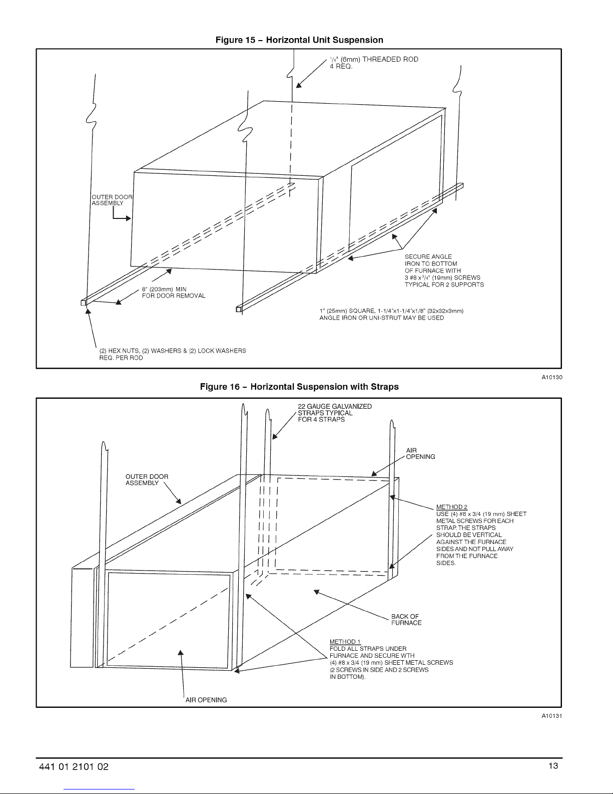
Figure 15 - Horizontal Unit Suspension
4 REQ.
UTER DOOR
ASSEMBLY
c.
8" (203mm) MIN
FOR DOOR REMOVAL
(2) HEX NUTS, (2) WASHERS & (2) LOCK WASHERS
REQ. PER ROD
l _/// 1/4" (6mm) THREADED ROD
SECURE ANGLE
IRON TO BOTTOM
OF FURNACE WiTH
3 #8 xS/4'' (19ram) SCREWS
TYPICAL FOR 2 SUPPORTS
1" (25mm) SQUARE, 1-1/4"xl-1/4"xt/8" (32x32x3mm)
ANGLE IRON OR UNI-STRUT MAY BE USED
J
Figure 16 - Horizontal Suspension with Straps
OUTER DOOR
ASSEMBLY X III I
IIII
22 GAUGE GALVANIZED
STRAPS TYPICAL
FOR 4 STRAPS
F
AIR
/OPENING
METHOD 2
USE (4) #8 x 3/4 (19 ram) SHEET
METAL SCREWS FOR EACH
STRAR THE STRAPS
SHQULD BE VERTICAL
AGAINST THE FURNACE
SIDES AND NOT PULL AWAY
FROM THE FURNACE
SIDES.
BACK OF
FURNACE
METHOD 1
FOLD ALL STRAPS UNDER
FURNACE AND SECURE WTH
(4) #8 x 3/4 (19 ram) SHEET METAL SCREWS
(2 SCREWS IN SIDE AND 2 SCREWS
IN BOTTOM).
A10130
AIR OPENING
441 01 2101 02 13
A10131
Page 14
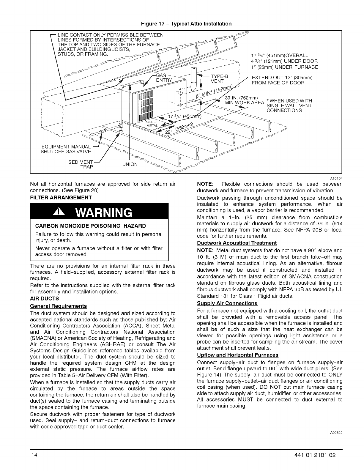
Figure 17 - Typical Attic Installation
LINE CONTACT ONLY PERMISSIBLE BETWEEN
LINES FORMED BY INTERSECTIONS OF
THE TOP AND TWO SIDES OF THE FURNACE
JACKET AND BUILDING JOISTS,
STUDS, OR FRAMING.
ENTRY
EQUIPMENT MANUAL
SHUT-OFF GAS VALVE
SEDIMENT UNION
TRAP
Not all horizontal furnaces are approved for side return air
connections. (See Figure 20)
FILTER ARRANGEMENT
CARBON MONOXIDE POISONING HAZARD
Failure to follow this warning could result in personal
injury, or death.
Never operate a furnace without a filter or with filter
access door removed.
There are no provisions for an internal filter rack in these
furnaces. A field-supplied, accessory external filter rack is
required.
Refer to the instructions supplied with the external filter rack
for assembly and installation options.
AIR DUCTS
General Requirements
The duct system should be designed and sized according to
accepted national standards such as those published by: Air
Conditioning Contractors Association (ACCA), Sheet Metal
and Air Conditioning Contractors National Association
(SMACNA) or American Society of Heating, Refrigerating and
Air Conditioning Engineers (ASHRAE) or consult The Air
Systems Design Guidelines reference tables available from
your local distributor. The duct system should be sized to
handle the required system design CFM at the design
external static pressure. The furnace airflow rates are
provided in Table 5-Air Delivery CFM (With Filter).
When a furnace is installed so that the supply ducts carry air
circulated by the furnace to areas outside the space
containing the furnace, the return air shall also be handled by
duct(s) sealed to the furnace casing and terminating outside
the space containing the furnace.
Secure ductwork with proper fasteners for type of ductwork
used. Seal supply- and return-duct connections to furnace
with code approved tape or duct sealer.
17 3/4" (451 mm)OVERALL
4 3/4" (121mm) UNDER DOOR
1" (25mm) UNDER FURNACE
VENT
30-IN. (762mm)
MIN WORKAREA *WHEN USED WITH
EXTEND OUT 12" (305mm)
FROM FACE OF DOOR
SINGLE WALL VENT
CONNECTIONS
A10164
NOTE: Flexible connections should be used between
ductwork and furnace to prevent transmission of vibration.
Ductwork passing through unconditioned space should be
insulated to enhance system performance. When air
conditioning is used, a vapor barrier is recommended.
Maintain a 1-in. (25 mm) clearance from combustible
materials to supply air ductwork for a distance of 36 in. (914
mm) horizontally from the furnace. See NFPA 90B or local
code for further requirements.
Ductwork Acoustical Treatment
NOTE: Metal duct systems that do not have a 90 _'elbow and
10 ft. (3 M) of main duct to the first branch take-off may
require internal acoustical lining. As an alternative, fibrous
ductwork may be used if constructed and installed in
accordance with the latest edition of SMACNA construction
standard on fibrous glass ducts. Both acoustical lining and
fibrous ductwork shall comply with NFPA 90B as tested by UL
Standard 181 for Class 1 Rigid air ducts.
Supply Air Connections
For a furnace not equipped with a cooling coil, the outlet duct
shall be provided with a removable access panel. This
opening shall be accessible when the furnace is installed and
shall be of such a size that the heat exchanger can be
viewed for possible openings using light assistance or a
probe can be inserted for sampling the air stream. The cover
attachment shall prevent leaks.
Upflow and Horizontal Furnaces
Connect supply-air duct to flanges on furnace supply-air
outlet. Bend flange upward to 90 ° with wide duct pliers. (See
Figure 14) The supply-air duct must be connected to ONLY
the furnace supply-outlet-air duct flanges or air conditioning
coil casing (when used). DO NOT cut main furnace casing
side to attach supply air duct, humidifier, or other accessories.
All accessories MUST be connected to duct external to
furnace main casing.
A02329
14 441 01 2101 02
Page 15
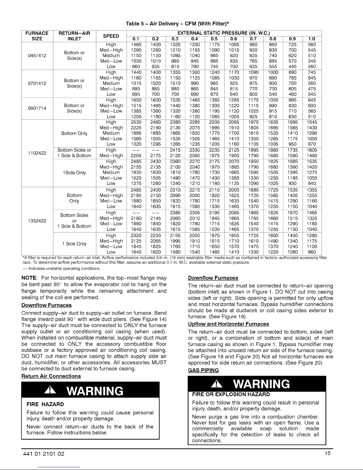
Table 5 - Air Delivery - CFM (With Filter)*
FURNACE
SIZE
0451412
0701412
0901714
1102422
1352422
rack. To determine airflow performance without this filter, assume an additional 0.1 In. W.C. available external static pressure.
-- Indicates unstable operating conditions.
NOTE: For horizontal applications, the top-most flange may
be bent past 90 ° to allow the evaporator coil to hang on the
flange temporarily while the remaining attachment and
sealing of the coil are performed.
Downflow Furnaces
Connect supply-air duct to supply-air outlet on furnace. Bend
flange inward past 90 ° with wide duct pliers. (See Figure 14)
The supply-air duct must be connected to ONLY the furnace
supply outlet or air conditioning coil casing (when used).
When installed on combustible material, supply-air duct must
be connected to ONLY the accessory combustible floor
subbase or a factory approved air conditioning coil casing.
DO NOT cut main furnace casing to attach supply side air
duct, humidifier, or other accessories. All accessories MUST
be connected to duct external to furnace casing.
RETURN-AIR
INLET
Bottom or
Side(s)
Bottom or
Side(s)
Bottom or
Side(s)
Bottom Only
Bottom Sides or
1 Side & Bottom
1Side Only
Bottom
Only
Bottom Sides
or
1 Side & Bottom
1 Side Only
SPEED
High 1465 1400 1325 1250 1175 1085 980 860 725 560
Med-High 1295 1260 1210 1155 1090 1015 930 830 700 545
Medium 1150 1120 1085 1040 985 920 835 740 620 510
Med-Low 1030 1010 980 945 895 835 765 685 570 345
Low 860 835 810 780 745 700 635 555 445 260
High 1440 1400 1355 1300 1240 1170 1090 1000 890 745
Med-High 1180 1165 1150 1125 1085 1030 970 890 785 645
Medium 1015 1020 1010 990 965 925 875 800 700 560
Med-Low 885 885 880 865 845 815 770 700 605 475
Low 695 700 700 690 670 640 600 540 460 345
High 1650 1600 1535 1465 1385 1285 1175 1055 895 645
Med-High 1515 1485 1440 1380 1300 1220 1115 990 830 600
Med- Low 1385 1360 1320 1260 1195 1120 1025 915 710 565
Low 1205 1180 1160 1120 1065 1005 925 810 630 510
High 2530 2460 2380 2285 2200 2085 1970 1835 1695 1545
Med-High 2225 2190 2135 2075 1995 1910 1805 1695 1565 1430
Medium 1895 1885 1865 1820 1770 1700 1610 1520 1410 1290
Med-Low 1565 1555 1535 1505 1465 1410 1350 1265 1175 1050
Low 1320 1295 1265 1235 1205 1160 1105 1035 950 870
High .... 2415 2330 2235 2125 1995 1860 1735 1605
Med-High 2205 2175 2120 2065 1975 1900 1790 1685 1580 1460
High 2485 2430 2360 2270 2175 2070 1950 1825 1685 1535
Med-High 2155 2135 2100 2040 1970 1885 1790 1680 1560 1420
Medium 1830 1830 1810 1780 1730 1665 1595 1505 1395 1275
Med-Low 1520 1505 1490 1470 1430 1385 1330 1250 1165 1055
Low 1275 1260 1240 1210 1180 1135 1090 1025 930 840
High 2485 2400 2310 2215 2110 2000 1880 1725 1535 1355
Med-High 2195 2150 2090 2000 1920 1825 1720 1565 1405 1255
Med-Low 1880 1850 1820 1780 1715 1635 1540 1415 1290 1160
Low 1640 1635 1615 1585 1530 1465 1370 1255 1150 1040
High .... 2385 2305 2195 2085 1960 1825 1670 1465
Med-High 2180 2145 2060 2010 1945 1865 1765 1660 1515 1325
Med-Low 1880 1850 1820 1780 1715 1635 1540 1415 1290 1160
Low 1640 1635 1615 1585 1530 1465 1370 1255 1150 1040
High 2320 2250 2155 2055 1970 1855 1725 1600 1450 1280
Med-High 2125 2065 1995 1910 1815 1710 1610 1490 1340 1175
Med-Low 1845 1825 1765 1710 1650 1570 1475 1370 1240 1100
Low 1640 1620 1580 1540 1485 1410 1330 1220 1080 960
0.1 0.2 0.3 0.4 0.5 0.6 0.7 0.8 0.9 1.0
EXTERNAL STATIC PRESSURE (IN.W.C.)
Downflow Furnaces
The return-air duct must be connected to return-air opening
(bottom inlet) as shown in Figure 1. DO NOT cut into casing
sides (left or right). Side opening is permitted for only upflow
and most horizontal furnaces. Bypass humidifier connections
should be made at ductwork or coil casing sides exterior to
furnace. (See Figure 19)
Upflow and Horizontal Furnaces
The return-air duct must be connected to bottom, sides (left
or right), or a combination of bottom and side(s) of main
furnace casing as shown in Figure 1. Bypass humidifier may
be attached into unused return air side of the furnace casing.
(See Figure 18 and Figure 20) Not all horizontal furnaces are
approved for side return air connections. (See Figure 20)
GAS PIPING
Return Air Connections
accessoryfilter*A filter is required for each return-air inlet. Airflow performance included 3/4-in. (19 mm) washable filter media such as contained in factory-authorized
FIRE HAZARD
Failure to follow this warning could cause personal
injury, death and/or property damage.
Never connect return-air ducts to the back of the
furnace. Follow instructions below.
441 01 2101 02 15
FIRE OR EXPLOSION HAZARD
Failure to follow this warning could result in personal
injury, death, and/or property damage.
Never purge a gas line into a combustion chamber.
Never test for gas leaks with an open flame. Use a
commercially available soap solution made
specifically for the detection of leaks to check all
connections.
Page 16
FIRE OR EXPLOSION HAZARD
Failure to follow this warning could result in )ersonat
injury, death, and/or property damage.
Use proper length of pipe to avoid stress on gas
control manifold and a gas leak.
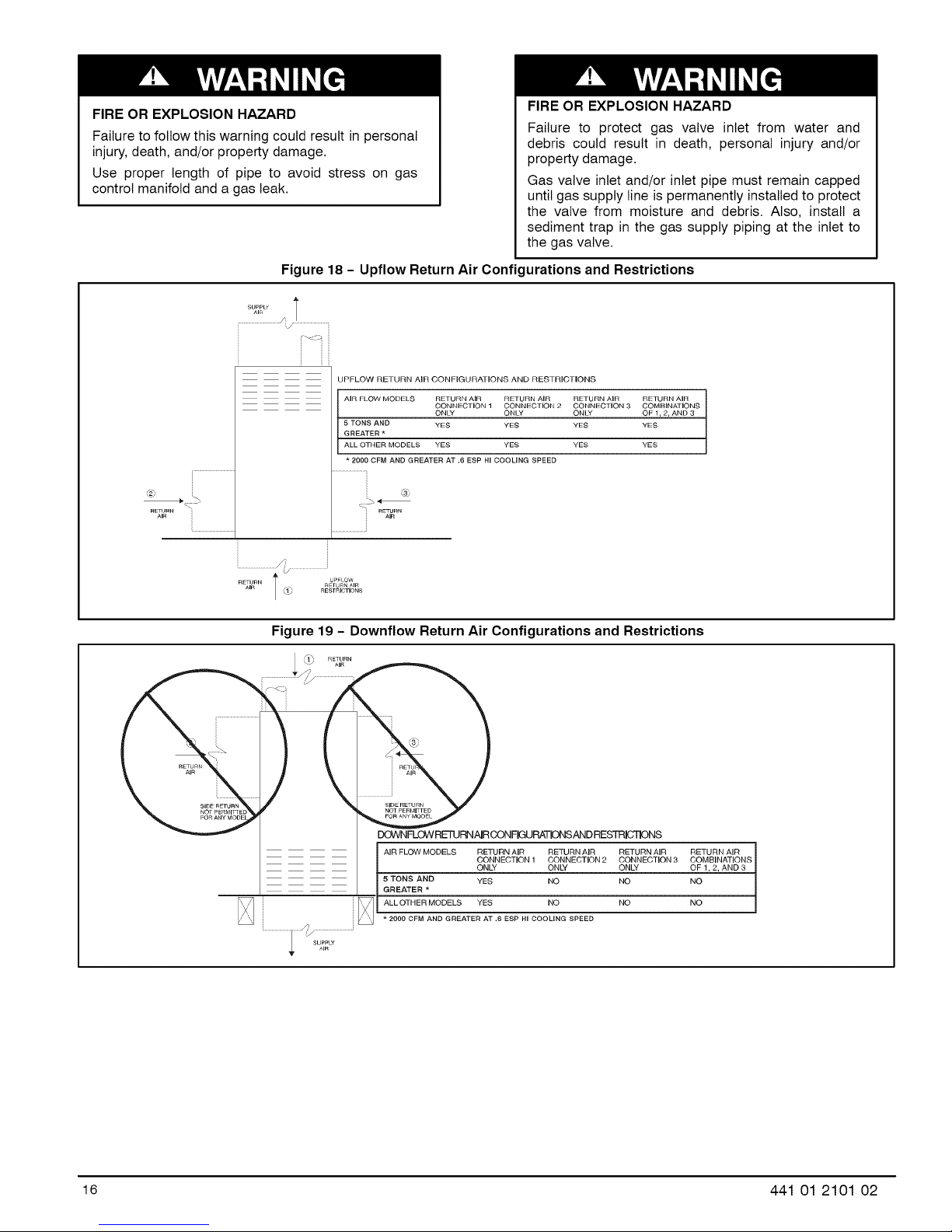
Figure 18 - Upflow Return Air Configurations and Restrictions
UPFLOW RETURN AiR CONFiGURATiONS AND RESTRICTIONS
AIR FLOW MODELS RETURN AIR RETURN AIR RETURN AIR RETURN AIR
GREATER *
5 TONS AND YES YES YES YES
ALL OTHER MODELS YES YES YES YES
• 2000 CFM AND GREATER AT .6 ESP HI COOLING SPEED
@
RETURN "i
AIR
RETURN
AiR
FIRE OR EXPLOSION HAZARD
Failure to protect gas valve inlet from water and
debris could result in death, personal injury and/or
property damage.
Gas valve inlet and/or inlet pipe must remain capped
until gas supply line is permanently installed to protect
the valve from moisture and debris. Also, install a
sediment trap in the gas supply piping at the inlet to
the gas valve.
CONNECTION 1 CONNECTION 2 CONNECTION 3 COMBINATIONS
ONLY ONLY ONLY OF 1,2, AND 3
RETURN / UPFLOW
AiR / RETURN AIR
RESTRICTIONS
Figure 19 - Downflow Return Air Configurations and Restrictions
,FI_ RETURN
_J AI R
RETURN
AIR AIR
DOWNFLOWRETURNAIRCONFIGURATIONSANDRESTRICq]ONS
AIR FLOW MODELS RETURN AIR RETURN AIR RETURN AIR RETURN AIR
5 TONS AND YES NO NO NO
GREATER *
ALL OTHER MODELS YES NO NO NO
• 2000 CFM AND GREATER AT .6 ESP HI COOLING SPEED
CONNECTION 1 CONNECTION 2 CONNECTION 3 COMBiNATiONS
ONLY ONLY ONLY OF 1, 2, AND 3
16 441 01 2101 02
Page 17

Figure 20 - Horizontal Return Air Configurations and Restrictions
RETURN
AIR
_ SIDE RETURN AIR
_ NOT PERMITIED FOR
066,060, -22-2O
AIR FLOW MODELS
..............................i
AIR
RETURN {
' ' ,/_ SIDERETURNAIR
/ 066,060,-22-20
AIR FLOW MODELS
......................_///.................................
HNORTzE6NRAELSTLREICFTTI......... ,_ ........ ICTIONS
J RETURN RETURN AIR
_s_ | HORIZONTAL RETURN AIR CONFIGURATIONS AND RESTRICTIONS
AiR FLOW MODELS RETURN AiR RETURN AIR RETURN AIR RETURN AIR
5 TONS AND YES NO NO NO
GREATER *
ALL OTHER MODELS YES YES YES YES
• 2000 CFM AND GREATER AT .6 ESP HI COOLING SPEED
ii iiiiii/iiiii
CONNECTION 1 CONNECTION 2 CONNECTION 3 COMBiNATiONS
ONLY ONLY ONLY OF 1,2, AND 3
Gas piping must be installed in accordance with national and
local codes. Refer to current edition of NFGC in the U.S.
Table 6 - Maximum Capacity of Pipe
NOMINAL
IRON PIPE
SIZE
IN. (MM)
1/2 (12.7)
3/4 (19.0)
1(25.4)
1-1/4
(31.8)
1-1/2 900
(38.1)
* Cubic ft. of natural gas per hr for gas pressures of 0.5 psig (14-1n. W.C.) or
less and a pressure drop of 0.5-In. W.C. (based on a 0.60 specific gravity
gas). Ref: Table 6 and NFPA54/ANSI Z223.1-2009.
INTERNAL LENGTH OF PIPE - FT. (M)
DIA. 10 20 30 40 50
IN. (MM) (3.0) (6.0) (9.1) (12.1) (15.2)
0.622
(158) 175 120 97 82 73
0.824
(20.9) 360 250 200 170 151
1.049
(26.6) 680 465 375 320 285
1.380
(35.0) 1400 950 770 660 580
1.610
(40.9) 2100 1460 1180 990
Installations must be made in accordance with all authorities
having jurisdiction. If possible, the gas supply line should be a
separate line running directly from meter to furnace.
NOTE: In the state of Massachusetts:
1. Gas supply connections MUST be performed by a
licensed plumber or gas fitter.
2. When flexible connectors are used, the maximum
length shall not exceed 36 inches (915 mm).
3. When lever handle type manual equipment shutoff
valves are used, they shall be T-handle valves.
4. The use of copper tubing for gas piping is NOT
approved by the state of Massachusetts.
Refer to Table 6 for recommended gas pipe sizing. Risers
must be used to connect to furnace and to meter. Support all
gas piping with appropriate straps, hangers, etc. Use a
minimum of 1 hanger every 6 ft. (1.8 M). Joint compound
(pipe dope) should be applied sparingly and only to male
threads of joints. Pipe dope must be resistant to the action of
propane gas.
FIRE OR EXPLOSION HAZARD
Failure to follow this warning could result in personal
injury, death, and/or property damage.
If local codes allow the use of a flexible gas appliance
connector, always use a new listed connector. Do not
use a connector which has previously served another
gas appliance. Black iron pipe shall be installed at the
furnace gas control valve and extend a minimum of 2
in. (51 mm) outside the furnace.
FURNACE DAMAGE HAZARD
Failure to follow this caution may result in furnace
damage.
Connect gas pipe to furnace using a backup wrench
to avoid damaging gas controls and burner
misatignment.
An accessible manual equipment shutoff valve MUST be
installed external to furnace casing and within 6 ft. of furnace.
A 1/8-in. (3 mm) NPT plugged tapping, accessible for test
gauge connection, MUST be installed immediately upstream
of gas supply connection to furnace and downstream of
manual equipment shutoff valve.
NOTE: The furnace gas control valve inlet pressure tap
connection is suitable to use as test gauge connection
providing test pressure DOES NOT exceed maximum 0.5
psig (14-1n. W.C.) stated on gas control valve. (See
Figure 48) Some installations require gas entry on right side
of furnace (as viewed in upfiow). (See Figure 21)
441 01 2101 02 17
Page 18

Figure 21 - Burner and Manifold
TOP VIEW OF BURNER AND MANIFOLD ASSEMBLY
90 ° EIbow_
Supply
2" (51 mm)Nipple
L Gas Valve
A08551
Install a sediment trap in riser leading to furnace as shown in
Figure 22. Connect a capped nipple into lower end of tee.
Capped nipple should extend below level of furnace gas
controls. Place a ground joint union between furnace gas
control valve manifold and exterior manual equipment gas
shutoff valve.
Figure 23 - Field Wiring Diagram
NOTE2
Figure 22 - Typical Gas Pipe Arrangement
GAS
SUPPLY,Z'[
MANUALJ II
SHUTOFF _ _
VALVE
(REQUIRED)jf*_.)_
SEDIMENT-- /
TRAP /
UNION---_
....................FIELD 24-VOLT WIRING
.... FIELD 115- 208/230-, 460-VOLT WIRING
-- FACTORY 24-VOLT WIRING
FACTORY 115-VOLT W_RING
A02035
115-VOLT FIELD-
SUPPL}ED
FUSED
DISCONNECT
CONTROL
FURNACE
BOX
TERMINAL
BLOCK
NOTES: 1. Oor_r_ect Y!Y24erm hal as shown for proper operation.
A 1/8-in. (3 mm) NPT plugged tapping, accessible for test
gauge connection, MUST be installed immediately upstream
of gas supply connection to furnace and downstream of
manual equipment shutoff valve.
Piping should be pressure and leak tested in accordance with
NFGC in the United States, local, and national plumbing and
gas codes before the furnace has been connected. After all
connections have been made, purge lines and check for
leakage at furnace prior to operating furnace.
If pressure exceeds 0.5 psig (14-1n. W.C.), gas supply pipe
must be disconnected from furnace and capped before and
during supply pipe pressure test. If test pressure is equal to or
less than 0.5 psig (14-1n. W.C.), turn off electric shutoff switch
located on furnace gas control valve and accessible manual
equipment shutoff valve before and during supply pipe
pressure test. After all connections have been made, purge
lines and check for leakage at furnace prior to operating
furnace.
CONDENSING
UNIT
2. Some thermostats require a 'C" terminal connection as shown.
3. If any of the original wire, as supplied, must be replace6, use
same type or equivalent wire.
The gas supply pressure shall be within the maximum and
minimum inlet supply pressures marked on the rating plate
with the furnace burners ON and OFF.
ELECTRICAL CONNECTIONS
ELECTRICAL SHOCK HAZARD
Failure to follow this warning could result in personal
injury or death.
Blower access panel door switch opens 115-v power
to control. No component operation can occur. Do not
bypass or close switch with panel removed.
See Figure 23 for field wiring diagram showing typical field
115-v wiring. Check all factory and field electrical
connections for tightness.
Field-supplied wiring shall conform with the limitations of
63°F (33°C) rise.
18 441 01 2101 02
Page 19

ELECTRICAL SHOCK AND FIRE HAZARD
Failure to follow this warning could result in personal
injury, death, or property damage.
The cabinet MUST have an uninterrupted or
unbroken ground according to NEC ANSI/NFPA
70-2008 or local codes to minimize personal injury if
an electrical fault should occur. This may consist of
electrical wire, conduit approved for electrical ground
or a listed, grounded power cord (where permitted by
local code) when installed in accordance with existing
electrical codes. Refer to the power cord
manufacturer's ratings for proper wire gauge. Do not
use gas piping as an electrical ground.
Table 7 - Electrical Data
FURNACE MAY NOT OPERATE HAZARD
Failure to follow this caution may result in intermittent
furnace operation.
Furnace control must be grounded for proper
operation or else control will lock out. Control must
remain grounded through green/yellow wire routed to
gas valve and manifold bracket screw.
115-V WIRING
Verify that the voltage, frequency, and phase correspond to
that specified on unit rating plate. Also, check to be sure that
service provided by utility is sufficient to handle load imposed
by this equipment. Refer to rating plate or Table 7 for
equipment electrical specifications.
FURNACE
SIZE
0451412 115-60-1 7.1 9.67 14
0701412 115-60-1 7.3 9.90 14
0901714 115-60-1 8.2 10.84 14
1102122 115-60-1 13.7 17.60 12
1352422 115-60-1 14.5 18.61 12
* Permissible limits of the voltage range at which the unit operates satisfactorily.
# Unit ampacity = 125% of largest operating component's full load amps plus 100% of all other potential operating components (EAC, humidifier,
etc.) full load amps.
1-Time-delay type is recommended.
$ Length shown is as measured 1 way along wire path between unit and service panel for maximum 2% voltage drop.
VOLTS-
HERTZ-
PHASE
U.S. Installations: Make all electrical connections in
accordance with National Electrical Code (NEC) ANSI/NFPA
70-2008 and any local codes or ordinances that might apply.
OPERATING VOLTAGE
RANGE
MAX* MIN.*
127 104
127 104
127 104
127 104
127 104
MAX UNIT
AMPS
UNIT
AMPACITY#
NOTE: The J-Box cover need not be removed from the
J-Box in order to move the J-Box. Do NOT remove green
ground screw inside J-Box.
MAXIMUM
WIRE
LENGTH
FT, (i)$
38 (11.5)
37 (11.2)
34 (10.3)
32 (9.7)
30 (9.1)
MAXIMUM
FUSE OR
CKT BKR
AMPSI
15
15
15
20
20
2. Cut wire tie on loop in furnace wires attached to J-Box.
3. Move J-Box to desired location.
FIRE HAZARD
Failure to follow this warning could result in personal
injury, death, or property damage.
Do not connect aluminum wire between disconnect
4. Fasten J-Box to casing with the two screws removed
in Step 1.
5. Route J-Box wires within furnace away from sharp
edges, rotating parts, and hot surfaces.
Figure 24 - Relocating J-Box
switch and furnace. Use only copper wire.
Use a separate branch electrical circuit with a properly sized
fuse or circuit breaker for this furnace. See Table 7 for wire
size and fuse specifications. A readily accessible means of
electrical disconnect must be located within sight of the
FACTORY
INSTALLED
LOCATION
furnace.
NOTE: Proper polarity must be maintained for 115-v wiring.
If polarity is incorrect, control LED status indicator light will
flash status code of 10 and furnace wilt NOT operate.
J-BOX RELOCATION
NOTE: If factory location of J-Box is acceptable, go to next
section (ELECTRICAL CONNECTION TO J-BOX).
NOTE: On 14" wide casing models, the J-Box shall not be
relocated to other side of furnace casing when the vent pipe
is routed within the casing.
1. Remove and save two screws holding J-Box. (See
Figure 24)
MINIMUM
WIRE
GAUGE
ALTERNATE
FIELD
LOCATION
441 01 2101 02 19
Page 20

ELECTRICAL CONNECTION TO J-BOX
6. Reinstall cover to J-Box. Do not pinch wires between
cover and bracket.
Electrical Box on Furnace Casing Side, See Figure 25
FIRE OR ELECTRICAL SHOCK HAZARD
Failure to follow this warning could result in personal
injury, death, or property damage.
If field-supplied manual disconnect switch is to be
mounted on furnace casing side, select a location
where a drill or fastener cannot damage electrical or
gas components.
Figure 25 - Field-Supplied Electrical Box on Furnace
Casing
©
1. Select and remove a hole knockout in the casing
where the electrical box is to be installed.
NOTE: Check that duct on side of furnace will not interfere
with installed electrical box.
2. Remove the desired electrical box hole knockout and
position the hole in the electrical box over the hole in
the furnace casing.
3. Fasten the electrical box to casing by driving two
field-supplied screws from inside electrical box into
casing steel.
4. Remove and save two screws holding J-Box. (See
Figure 24)
5. Pull furnace power wires out of 1/2-inch (12 mm)
diameter hole in J-Box. Do not loosen wires from
strain-relief wire-tie on outside of J-Box.
6. Route furnace power wires through holes in casing and
electrical box and into electrical box.
7. Pull field power wires into electrical box.
8. Remove cover from furnace J-Box.
9. Route field ground wire through holes in electrical box
and casing, and into furnace J-Box.
10. Reattach furnace J-Box to furnace casing with screws
removed in Step 4.
11. Secure field ground wire to J-Box green ground screw.
12. Complete electrical box wiring and installation. Connect
line voltage leads as shown in Figure 23. Use best
practices (NEC in U.S. for wire bushings, strain relief,
etc.
13. Reinstall cover to J-Box. Do not pinch wires between
cover and bracket.
POWER CORD INSTALLATION IN FURNACE J-BOX
NOTE: Power cords must be able to handle the electrical
requirements listed in Table 7. Refer to power cord
manufacturer's listings.
1. Remove cover from J-Box.
2. Route listed power cord through 7/8-inch (22 mm)
diameter hole in J-Box.
3. Secure power cord to J-Box bracket with a strain relief
bushing or a connector approved for the type of cord
used.
4. Secure field ground wire to green ground screw on
J-Box bracket.
5. Connect line voltage leads as shown in Figure 23.
6. Reinstall cover to J-Box. Do not pinch wires between
cover and bracket.
BX, CABLE INSTALLATION IN FURNACE J-BOX
1. Remove cover from J-Box.
2. Route BX cable into 7/8-inch (22 mm) diameter hole in
J-Box.
3. Secure BX cable to J-Box bracket with connectors
approved for the type of cable used.
4. Secure field ground wire to green ground screw on
J-Box bracket.
5. Connect line voltage leads as shown in Figure 23.
6. Reinstall cover to J-Box. Do not pinch wires between
cover and bracket.
24-V WIRING
Make field 24-v connections at the 24-v terminal strip. (See
Figure 23) Connect terminal Y/Y2 as shown in
Figure 26-Figure 32 for proper cooling operation. Use only
AWG No. 18, color-coded, copper thermostat wire.
The 24-v circuit contains an automotive-type, 3-amp. fuse
located on the control. Any direct shorts during installation,
service, or maintenance could cause this fuse to blow. If fuse
replacement is required, use ONLY a 3-amp. fuse of identical
size.
20 441 01 2101 02
Page 21

Figure 26 - Two-Stage Furnace with Single-Speed Air
ICP THERMOSTAT TWO-STAGE SINGLE-,STAGE
Conditioner
FURNACE AIR CONDITIONER
NOTE 5
F_q
F_q
_q
F_q
Fq
[]
Figure 28 - Two-Stage Furnace with Single-Stage Heat
Pump (Dual Fuel)
ICP THERMOSTAT TWO-STAGE SINGLE-STAGE
NOTE 5
F_q
E_
FURNACE HEAT PUMP
F_q
F_q
NOTE4
Fq
SENSOR
OUTDOOR ]__]
Seenotesl, 3,4, and5
Figure 27 - Two-Stage Furnace with Two-Stage Air
ICP THERMOSTAT TWO-,STAGE TWO-STAGE
C_-
C_-
EZ_
Conditioner
FURNACE AIR CONDITIONER
NOTE5
F_q
F_q
-E3
[]
E35
NOTE4
E2_
D HUM24VAC
EZ}
EZ_
E_
See notes 1, 2, 3, 4, 5, and 8
Figure 29 - Two-Stage Furnace with Two-Stage Heat
ICP THERMOSTAT TWO-STAGE TWO-STAGE
NOTE 5 _F_" _
OUTDOOR
SENSOR I
Pump (Dual Fuel)
FURNACE HEAT PUMP
C_-
E2_
E25
NOTE4
C_-
Fq
D HUM
24VAC
E2_
NOTE4 _['_'q
p-q
HUM
24VAC
OUTDOOR
SENSOR
I
See notes 1, 3, 4, and 5
EZ}
E_5
See notes 1,2, 3, 4, 5, and 8
441 01 2101 02 21
OUTDOOR
SENSOR I
Page 22

Figure 30 - Two-Stage Furnace and Humidifier Only
HUMIDITY SENSING
THERMOSTAT
HUMIDIFIER
TWO-STAGE
FURNACE
Figure 32 - HP with Two-Stage Furnace, Humidifier, and
Dehumidification
HUMIDITY SENSING TWO-,STAGE
THERMOSTAT FURNACE
See note 7
Figure 31 - AC with Two-Stage Furnace, Humidifier, and
HUMIDITY SENSlNG
THERMOSTAT
Dehumidification
"RNO--STAG E
FURNAC E
-0
SPDT f
RELAY
HUMIDIFIER
See notes 6 and 7
SPOTil
RELAY
HUMIDIFIER i
See note 7
For Figure 26 - Figure 32
1. Refer to outdoor equipment Installation Instructions for
additional information and setup procedure.
2. Outdoor Air Temperature Sensor must be attached in
all dual fuel application.
3. Refer to ICP thermostat Installation Instructions for
additional information and setup procedure.
4. When using a Humidity Sensing Thermostat, set
DEHUMIDIFY OPTIONS to H DE-ENRGZD FOR
DEHUM
5. Optional connection for Two-Stage: If wire is
connected, SWl-I(TT) on furnace control should be
set to ON position to allow ICP Thermostat to control
the furnace staging.
6. HUM 24VAC terminal is 24 VAC and is energized when
the low pressure switch closes during a call for heat.
7. When connecting 115VAC to humidifier use a separate
115 VAC supply.
8. When using a humidifier on a HP installation, connect
humidifier to hot water.
22 441 01 2101 02
Page 23

ACCESSORIES
1. Electronic Air Cleaner (EAC): Connect an accessory
Electronic Air Cleaner (if used) using 1/4-in female
quick connect terminals to the two male 1/4-in
quick-connect terminals on the control board marked
EAC 1AMP and NEUTRAL. The terminals are rated for
115VAC, 1.0 amps maximum and are energized during
blower motor operation. (See Figure 33)
2. Humidifier (HUM 24VAC and HUM)
a. HUM 24VAC: Connect an accessory 24 VAC, 0.5
amp maximum humidifier (if used) to the X-in male
quick-connect HUM 24VAC terminal and C screw
terminal on the control board thermostat strip. The
HUM 24VAC terminal is energized when there is a
call for heat (W) and the pressure switch (PRS)
closes. (See Figure 33 and Figure 55).
b.. HUM: connect an accessory 115VAC (EAC and
HUM and 1 amp maximum combined) humidifier (if
used) to the ¼-in male quick connect HUM terminal
and NEUTRAL X-in QUICK CONNECT. THE hum
terminal is energized when the inducer motor is
energized (IDR). (See Figure 33 and Figure 55).
Figure 33 - Furnace ControI-PSC Blower Motor
SETUP SWITCHES THER-
MOSTAT TYPE AND HEAT
OFF-DELAY _
-- wo o_
NOTE: A field-supplied, 115-v controlled relay connected to
EAC terminals may be added if humidifier operation is
desired during blower operation.
NOTE: DO NOT connect furnace control HUM 24VAC
terminal to H (humidifier) terminal on humidity sensing
thermostat, or similar device. See humidity sensing
thermostat, thermostat, or controller manufacturer's
instructions for proper connection.
VENTING
The furnace shall be connected to a listed factory built
chimney or vent or a clay-tile lined masonry or concrete
chimney. Venting into an unlined masonry chimney or
concrete chimney is prohibited. When an existing Category I
furnace is removed or replaced, the original venting system
may no longer be sized to properly vent the attached
appliances. An improperly sized Category I venting system
could cause the formation of condensate in the furnace and
vent, leakage of condensate and combustion products, and
spillage of combustion products into the living space.
TWINNING AND/OR
COMPONENT TEST
TERMINAL
24-V THERMOSTAT
TERMINALS
3-AMP FUSE -
LED OPERATION &
DIAGNOSTIC LIGHT
115-VAC (L2) NEUTRAL
CONNECTIONS
SELECTION TERMINALS
HUMIDIFIER TERMINAL
(24-VAC 0,5 AMP MAX)
F'_ TRANSFORMER 24VAC
//7 CONNECTIONS
HARNESS CONNECTOR
_ _IVI_ _ P1 - LOW VOLTAGE_MAIN
BHI/LOR
P2-HQT SURFACE IGNITOR (HSI) &
INDUCER MOTOR CONNECTOR
TER L 115 VAC (L1) LINE
(115 VAC 1,0 AMP MAX,) VOLTAGE CONNECTION
I
L09F023
441 01 2101 02 23
Page 24

CARBON MONOXIDE POISONING HAZARD
Failure to follow this warning could result in personal
injury or death.
Failure to follow the steps outlined below for each
appliance connected to the venting system being placed
into operation could result in carbon monoxide poisoning
or death. The following steps shall be followed for each
appliance connected to the venting system being placed
into operation, while all other appliances connected to the
venting system are not in operation:
1. Seal any unused openings in venting system.
2. Inspect the venting system for proper size and
horizontal pitch, as required in the National Fuel Gas
Code, ANSI Z223.1/NFPA 54, and these instructions.
Determine that there is no blockage or restriction,
leakage, corrosion and other deficiencies, which could
cause an unsafe condition.
3. As far as practical, close all building doors and
windows and all doors between the space in which the
appliance(s) connected to the venting system are located
and other spaces of the building.
4. Close fireplace dampers.
5. Turn on clothes dryers and any appliance not
connected to the venting system. Turn on any exhaust
fans, such as range hoods and bathroom exhausts, so
they are operating at maximum speed. Do not operate a
summer exhaust fan.
6. Follow the lighting instructions. Place the appliance
being inspected into operation. Adjust the thermostat so
appliance is operating continuously.
7. Test for spillage from draft hood equipped appliances
at the draft hood relief opening after 5 minutes of main
burner operation. Use the flame of a match or candle.
8. If improper venting is observed during any of the
above tests, the venting system must be corrected in
accordance with the National Fuel Gas Code, ANSI
Z223.1/NFPA 54.
9. After it has been determined that each appliance
connected to the venting system properly vents when
tested as outlined above, return doors, windows, exhaust
fans, fireplace dampers and any other gas-fired burning
appliance to their previous conditions of use.
Vent system or vent connectors may need to be resized. Vent
systems or vent connectors must be sized to approach
minimum size as determined using appropriate table found in
the NFGC.
GENERAL VENTING REQUIREMENTS
Follow all safety codes for proper vent sizing and installation
requirements, including local building codes, the National
Fuel Gas Code ANSI Z223.1-2009/NFPA 54-2009 (NFGC),
Parts 12 and 13 in the United States, the local building codes,
and furnace and vent manufacturers' instructions.
These furnaces are design-certified as Category I furnaces in
accordance with ANSI Z21.47-2006/CSA 2.3-2006 and
operate with a non-positive vent static pressure to minimize
the potential for vent gas leakage. Category I furnaces
operate with a flue loss not less than 17% to minimize the
potential for condensation in the venting system. These
furnaces are approved for common venting and multi-story
venting with other fan assisted or draft hood equipped
appliances in accordance with the NFCG, local building
codes, and furnace and vent manufacturers' instructions.
The following information and warning must be considered in
addition to the requirements defined in the NFGC.
CARBON MONOXIDE POISONING HAZARD
Failure to follow this warning could result in personal
injury or death.
Do not bypass the draft safeguard switch, as an
unsafe condition could exist which must be corrected.
1. If a vent (common or dedicated) becomes blocked, the
furnace will be shut off by the draft safeguard switch
located on the vent elbow.
2. Two-stage furnaces require Type B vent connectors
outside the casing in all configurations. Single wall vent
connector may be used inside the furnace casing with
the transition to Type B vent outside the furnace
casing. Size the connector so that the FAN-Min vent
connector capacity is equal to or lower than the low fire
rate of the furnace and the FAN-Max vent connector
capacity is equal to or higher than the furnace high fire
rate.
3. Do not vent this Category I furnace into a single wall
dedicated or common vent. The dedicated or common
vent is considered to be the vertical portion of the vent
system that terminates outdoors.
4. Vent connectors serving Category I furnaces shall not
be connected into any portion of a mechanical draft
system operating under positive pressure.
5. Do not vent this appliance with any solid fuel burning
appliance.
6. Category I furnaces must be vented vertically or nearly
vertically unless equipped with a listed mechanical
venter. See the SIDEWALL VENTING section.
7. Do not vent this appliance into an unlined masonry
chimney. Refer to Chimney Inspection Chart,
Figure 34.
MASONRY CHIMNEY REQUIREMENTS
NOTE: These furnaces are CSA design-certified for use in
exterior tile-lined masonry chimneys with a factory accessory
Chimney Adapter Kit. Refer to the furnace rating plate for
correct kit usage. The Chimney Adapter Kits are for use with
ONLY furnaces having a Chimney Adapter Kit number
marked on the furnace rating plate.
If a clay tile-lined masonry chimney is being used and it is
exposed to the outdoors below the roof line, relining might be
required. Chimneys shall conform to the Standard for
Chimneys, Fireplaces, Vents, and Solid Fuel Burning
Appliances ANSI/NFPA 211-2009 in the United States and
must be in good condition.
U.S.A.-Refer to Sections 13.1.8 and 13.2.20 of the NFPA 54
/ ANSI Z223.1-2009 or the authority having jurisdiction to
determine whether relining is required. If relining is required,
use a properly sized listed metal liner, Type-B vent, or a
listed alternative venting design.
NOTE: See the NFPA 54 / ANSI Z223.1-2009, 13.1.8 and
13.2.20 regarding alternative venting design and the
exception, which cover installations such as the Chimney
Adapter Kits which are listed for use with these furnaces. The
Chimney Adapter is listed alternative venting system for these
furnaces. See the kit instructions for complete details.
24 441 01 2101 02
Page 25

Figure 34 - Chimney Inspection Chart
CHIMNEY INSPECTION CHART
For additional requirements refer to the National Fuel Gas Code NFPA 54/ANSI Z223.1 and ANSI/NFPA 211
Chimneys, Fireplaces, Vents, and Solid Fuel Burning Appliances
Rebuild
Crown.
prol_rct_ilim_Ywith -_ No
_ Reline
sale ing...cod _or reline chimney as/
residue? debris_''_t Mr'°;;ar?
_ve metal vent [ J No
or liner. J
Clay
tile misalignment,
missing sections,
Yes
gaps?
No
Condensate
at bottom
No
Chimney
exposed to
outdoors below
roof line?
No
_,- __perl.y _ ]Suitable sized, listed flexible metal
_b_ '_O '__ _chimney adapter ventingS_le
• _ .... _-_n,_ .... J"__ in§tructions for -_
Yes _ f"ur_a_e-? / _ applicatlon /
Remove mortar
and tile debris
_Not Suitable
_LNo _ instructions for / A_ b
/ _ _ application
.,_,=_^._ ,.._. _L^.,,. _ _ .... Line chimney with property
-.,_,_._.._u,._ ..... _' U'/Yes I liner or Type-B vent per
",_ype-u vent'._,,,/ _ NFGC Vent
/ _ Sizing Tables and liner or
_./ I"'_;_-_;,;';,T;_;;7'I vent manu
.[Yes L _ . Not Suitable
Is chimney _No . _ Part C of
Suitable
I i_;_ I Installationil
suitabili , ,
chimney]
I adapter per /
I instructions. /
441 01 2101 02 25
A10133
Page 26

The Chimney Adapter Kit is a listed alternative venting
system for these furnaces. See the kit instructions for
complete details.
This furnace is permitted to be vented into a clay tile-lined
masonry chimney that is exposed to the outdoors below the
roof line, provided:
1. Vent connector is Type-B double-wall, and
2. This furnace is common vented with at least 1 draft
hood-equipped appliance, and
3. The combined appliance input rating is less than the
maximum capacity given in Table 8, and
4. The input rating of each space heating appliance is
greater than the minimum input rating given in Table 9
for the local 99% Winter Design Temperature.
Chimneys having internal areas greater than 38 in2
(24516 mm2)require furnace input ratings greater than
the input ratings of these furnaces. See footnote at
bottom of Table 9, and
5. The authority having jurisdiction approves.
If all of these conditions cannot be met, an alternative venting
design shall be used, such as the listed chimney adapter kit
with a furnace listed for use with the kit, a listed
chimney-lining system, or a Type-B common vent.
Inspections before the sale and at the time of installation will
determine the acceptability of the chimney or the need for
repair and/or (re)lining. Refer to Figure 34 to perform a
chimney inspection. If the inspection of a previously used
tile-lined chimney:
a. Shows signs of vent gas condensation, the chimney
should be relined in accordance with local codes and
the authority having jurisdiction. The chimney should
be relined with a listed metal liner, Type-B vent, or a
listed chimney adapter kit shall be used to reduce
condensation. If a condensate drain is required by
local code, refer to the NFPA 54/ANSI Z223.1-2009,
Section 12.10 for additional information on
condensate drains.
b. Indicates the chimney exceeds the maximum
permissible size in the tables, the chimney should be
rebuilt or relined to conform to the requirements of the
equipment being installed and the authority having
jurisdiction.
A chimney without a clay tile liner, which is otherwise in good
condition, shall be rebuilt to conform to ANSl/NFPA 211 or be
lined with a UL listed metal liner or UL listed Type-B vent.
Relining with a listed metal liner or Type-B vent is considered
to be a vent-in-a-chase.
If a metal liner or Type-B vent is used to line a chimney, no
other appliance shall be vented into the annular space
between the chimney and the metal liner.
Exterior Masonry Chimney FAN + NAT
Installations with Type-B Double-Wall Vent
Connectors ©NFPA & AGA
Table 8 - Combined Appliance Maximum Input Rating in
Thousands of BTUH per Hour
VENT HEIGHT
FT. (M)
6 (1.8)
8 (2.4)
10 (3.0)
15 (4.5)
20 (6.0)
30 (9.1)
INTERNAL AREA OF CHIMNEY
SQ. IN. (SQ. MM)
12
(7741 )
74
8O
84
NR
NR
NR
19 28
(12258) (18064)
119 178
130 193
138 207
152 233
NR 250
NR NR
38
(24516)
257
279
299
334
368
404
Table 9 - Minimum Allowable Input Rating of
Space-Heating Appliance in Thousands of BTUH per
Hour
INTERNAL AREA OF CHIMNEY
VENT HEIGHT (FT)
Temperature: 17 to 26°F (-8 to -3°C)
6 (1.8) 0 55 99 141
8 (2.4) 52 74 111 154
10 (3.0) NR 90 125 169
15 (4.6) NR NR 167 212
20 (6.1) NR NR 212 258
30 (9.1) NR NR NR 362
Temperature: 5 to 16°F * (-15 to -9°C)
6 (1.8) NR 78 121 166
8 (2.4) NR 94 135 182
10 (3.0) NR 111 149 198
15 (4.6) NR NR 193 247
20 (6.1) NR NR NR 293
30 (9.1) NR NR NR 377
Temperature: -10 to 4°F * (-23 to -16°C)
6 (1.8) NR NR 145 196
8 (2.4) NR NR 159 213
10 (3.0) NR NR 175 231
15 (4.6) NR NR NR 283
20 (6.1) NR NR NR 333
30 (9.1) NR NR NR NR
Temperature: -11 °F (-24°C) or lower
Not recommended for any vent configuration.
*The 99.6% heating db temperatures found in the 1997 or 2001 ASHRAE
Fundamentals Handbook, Climatic Design Information chapter, Table 1A
(United States) or the 2005 ASHRAE Fundamentals handbook, Climatic
Design Information chapter, and the CD-ROM included with the 2005
ASHRAE Fundamentals Handbook.
12 19 28 38
(7741) (12258) (18064) (24516)
Local 99% Winter Design
Local 99% Winter Design
Local 99% Winter Design
Local 99% Winter Design
SQ, IN. (SQ, MM)
26 441 01 2101 02
Page 27

APPLIANCE APPLICATION REQUIREMENTS
Appliance operation has a significant impact on the
performance of the venting system. If the appliances are
sized, installed, adjusted, and operated properly, the venting
system and/or the appliances should not suffer from
condensation and corrosion. The venting system and all
appliances shall be installed in accordance with applicable
listings, standards, and codes.
The furnace should be sized to provide 100% of the design
heating load requirement plus any margin that occurs
because of furnace model size capacity increments. Heating
load estimates can be made using approved methods
available from Air Conditioning Contractors of America
(Manual J); American Society of Heating, Refrigerating, and
Air-Conditioning Engineers; or other approved engineering
methods. Excessive over-sizing of the furnace could cause
the furnace and/or vent to fail prematurely. When a metal vent
or metal liner is used, the vent must be in good condition and
be installed in accordance with the vent manufacturer's
instructions.
When a metal vent or metal liner is used, the vent must be in
good condition and be installed in accordance with the vent
manufacturer's instructions.
To prevent condensation in the furnace and vent system, the
following precautions must be observed:
1. The return-air temperature must be at least 60°F
(15°0) db except for brief periods of time during
warm-up from setback at no lower than 55_'F (13°0)
db or during initial start-up from a standby condition.
2. Adjust the gas input rate per the installation
instructions. Low gas input rate causes low vent gas
temperatures, causing condensation and corrosion in
the furnace and/or venting system. Derating is
permitted only for altitudes above 2000 ft
3. Adjust the air temperature rise to the midpoint of the
rise range or slightly above. Low air temperature rise
can cause low vent gas temperature and potential for
condensation problems.
4. Set the thermostat heat anticipator or cycle rate to
reduce short cycling.
Air for combustion must not be contaminated by halogen
compounds which include chlorides, fluorides, bromides, and
iodides. These compounds are found in many common home
products such as detergent, paint, glue, aerosol spray,
bleach, cleaning solvent, salt, and air freshener, and can
cause corrosion of furnaces and vents. Avoid using such
products in the combustion-air supply. Furnace use during
construction of the building could cause the furnace to be
exposed to halogen compounds, causing premature failure of
the furnace or venting system due to corrosion.
Vent dampers on any appliance connected to the common
vent can cause condensation and corrosion in the venting
system. Do not use vent dampers on appliances common
vented with this furnace.
ADDITIONAL VENTING REQUIREMENTS
A 4 in. (102 mm) round vent elbow is supplied with the
furnace. A 5 in. or 6 in. (127 or 152 mm) vent connector may
be required for some model furnaces. A field-supplied 4 in. to
5 in. (102 to 127 mm) or 4 in. to 6 in. (102 mm to 152 mm)
sheet metal increaser fitting is required when 5 in. or 6 in.
(127 or 152 mm) vent connector is used. See
Figure 35-Figure 47 Venting Orientation for approved vent
configurations.
See Venting Notes after orientation figures.
Figure 35 - Upflow Application-Vent Elbow Up
SEE NOTES: 1,2,4,7,8,9
on the page following
these figures
A03208
Figure 36 - Upflow Application-Vent Elbow Right
if¸,¸}
,j,
SEE NOTES: 1,2,3,4,7,8,9
on the pages following
these figures
A03209
441 01 2101 02 27
Page 28

Figure 37 - Downflow Application-Vent Elbow Up then
Left
Figure39 - DownflowApplication-Vent Elbow Left then
Up
SEE NOTES:1,2,3,4,5,7,8,9
on the page following
these figures
Figure 38 - Downflow Application-Vent Elbow Up
- = .
!'/ ix'
SEE NOTES: 1,2,4,5,7,8,9
on the page following
these figures
A03210
A03211
SEE NOTES: 1,2,4,5,6,7,8,9,10
on the page following these figures
A03207
Figure 40 - Downflow Application-Vent Elbow Up then
Right
SEE NOTES:1,2,3,4,5,7,8,9
on the page following
these figures.
A03212
28 441 01 2101 02
Page 29

Page 30

Page 31

Page 32

Page 33

Page 34

Page 35

Page 36

Page 37

Page 38

Page 39

Page 40

Page 41

Page 42

Page 43

Page 44

Page 45

(4.)Insertbrushendofcableinburnerinletopening
ofcell,andproceedtoclean2lowerpassesofcell
insamemannerasupperpass.
(5.)Repeatforegoingproceduresuntileachcellin
furnacehasbeencleaned.
(6.)Usingvacuumcleaner,removeresiduefrom
eachcell.
(7.)Usingvacuumcleanerwith soft brush
attachment,cleanburnerassembly.
(8.)Cleanflamesensorwithfinesteelwool.
(9.)InstallNOxbaffles(ifremoved.)
(10.)Reinstallburnerassembly.Centerburnersincell
openings.
10.Removeoldsealantfromcellpanelandcollectorbox
flange.
11.Sprayreleasingagentontheheatexchangercellpanel
wherecollectorboxassemblycontactscellpanel.
NOTE:A releasingagentsuchasavegetableoilcooking
spraythatdoesnotcontaincornoil,canolaoil,halogenated
hydrocarbonsoraromaticcontent,whichmaypreventan
inadequateseatfromoccuring,andRTVsealantsuchas
G.E.RTV162,G.E.RTV6702,orDow-CorningRTV738
sealantarerequired.DONOTsubstituteanyothertypeof
RTVsealant.
12.Applynewsealanttoflangeofcollectorboxandattach
tocellpanelusingexistingscrews,makingsureall
screwsaresecure.
13.Reconnectwiresto thefollowingcomponents(Use
connectiondiagramonwiringlabel,ifwireswerenot
markedforreconnectionlocations.):
a.Draftsafeguardswitch.
b.Inducermotor.
c.Pressureswitches.
d.Limitovertemperatureswitch.
e.Gasvalve.
f.Hotsurfaceigniter.
g.Flame-sensingelectrode.
h.Flamerolloutswitches.
14.Reinstallinternalventpipe,ifapplicable.
15.Reinstallvent connectoron furnaceventelbow.
Securelyfastenventconnectortoventelbowwith2
field-supplied,corrosion-resistant,sheetmetalscrews
located180° apart.
Figure 53 - Igniter Position-Top View
A05026
16. Replace blower access door only, if it was removed.
17. Set thermostat above room temperature and check
furnace for proper operation.
18. Verify blower airflow and speed changes between
heating and cooling.
19. Check for gas leaks.
20. Replace outer access door.
Figure 54 - Cleaning Heat Exchanger Cell
A91252
FIRE OR EXPLOSION HAZARD
Failure to follow this warning could result in personal
injury, death and/or property damage.
Never test for gas leaks with an open flame. Use a
commercially available soap solution made
specifically for the detection of leaks to check all
connections.
Step 3 m Sequence of Operation
NOTE: Furnace control must be grounded for proper
operation or control will lockout. Control is grounded through
green wire connected to gas valve and burner bracket screw.
Using the schematic diagram in Figure55, follow the
sequence of operation through the different modes. Read and
follow the wiring diagram very carefully.
NOTE: If a power interruption occurs during a call for heat
(W/W1 or W/Wl-and-W2), the control will run the blower for
the selected heat off-delay period two seconds after power is
restored, if the thermostat is still calling for gas heating. The
LED light wilt flash a status code 1+2 during this period, after
which the LED will switch to a heartbeat, as long as no faults
are detected. After this period, the furnace will respond to the
thermostat normally.
The blower door must be installed for power to be conducted
through the blower door interlock switch ILK to the furnace
control CPU, transformer TRAN, inducer motor IDM, blower
motor BLWM, hot-surface igniter HSI, and gas valve GV.
1. Two-Stage Heating with Single-Stage Thermostat
(See Figure 23 or Figure 32 for thermostat
connections)
NOTE: The thermostat type switch (TT) selects either the
two-stage thermostat operation mode when ON, (see item 2)
or the single stage thermostat operation mode when OFF in
response to a call for heat. When the W2 thermostat terminal
is energized it will always cause high-heat operation when
the R to W circuit is closed, regardless of the setting of the
thermostat type switch. This furnace can operate as a
two-stage furnace with a single-stage thermostat because
the furnace control CPU includes a programmed sequence of
controlled operation, which selects low-heat for the first 12
minutes of operation then switches to high heat operation.
If the power is interrupted, the control CPU will operate in low
heat for 12 minutes then it will switch to high-heat, as long as
the thermostat continues to call for heat.
The wall thermostat "calls for heat", closing the R to W circuit.
The furnace control performs a self-check, verifies the
low-heat and high-heat pressure switch contacts LPS and
HPS are open, and starts the inducer motor IDM in
441 01 2101 02 45
Page 46

high-speed. The HUM terminal is energized for a 115V
humidifier (if used).
a. Inducer Prepurge Period (see Figure 55 schematic
diagram)
(1.) Low heat (W/W1) the inducer motor IDM comes
up to high-speed, the low-heat pressure switch
LPS closes. After the low-heat pressure switch
closes the furnace control CPU will begin a
15-second prepurge period, and continue to run
the inducer motor IDM at high-speed.
(2.) High Heat (W/WI+W2) the inducer motor IDM
comes up to high speed and the high-heat
pressure switch relay HPSR is de-energized to
close the NO contact. When sufficient pressure
is available, the high-heat pressure switch HPS
closes, and the high-heat gas valve solenoid
GV-HI is energized. After LPS closes, 24VAC
power is supplied for a field-installed humidifier
at the HUM 24VAC terminal and the furnace
control CPU begins a 15-second prepurge
period. If the high-heat pressure switch HPS fails
to close and the low-heat pressure switch LPS
closes, the furnace will operate at low-heat gas
flow rate until the high-heat pressure switch
closes for a maximum of 2 minutes after ignition.
If HPS doesn't close after 2 minutes from LPS
closing, GV is turned off and heat off delay is
completed. Then a new cycle will begin if a call
for heat remains.
b. Igniter Warm-Up-At the end of the prepurge period,
the (Hot Surface Igniter) HSI is energized for a
17-second igniter warm-up period.
c. Trial-for-Ignition Sequence-When the igniter
warm-up period is completed the main gas valve relay
contacts GVR close to energize the gas valve solenoid
GV-M, the gas valve opens. The gas valve solenoid
GV-M permits gas flow to the burners where it is
ignited by the HSI. 5 sec after the GVR closes, a 2-sec
flame proving period begins. The HSI igniter will
remain energized until the flame is sensed or until the
2-sec flame proving period begins. If the furnace
control CPU operates in high-heat operation, the
high-heat gas valve solenoid GV-HI is also
energized.
d. Flame-Proving-When the burner flame is proved at
the flame-proving sensor electrode FSE, the inducer
motor IDM switches to low-speed unless running at
high-heat, and the furnace control CPU begins the
blower-ON delay period and continues to hold the gas
valve GV-M open. If the burner flame is not proved
within two seconds, the control CPU will close the gas
valve GV-M, and the control CPU will repeat the
ignition sequence for up to three more
Trials-For-Ignition before going to Ignition- Lockout.
Lockout will be reset automatically after three hours,
or by momentarily interrupting 115 vac power to the
furnace, or by interrupting 24 vac power at 24VAC or
COM to the furnace control CPU (not at W/W1, G, R,
etc.). If flame is proved when flame should not be
present, the furnace control CPU wilt lock out of
Gas-Heating mode and operate the inducer motor
IDM on high speed until flame is no longer proved.
e. Blower On Delay-If the burner flame is proven, the
blower on delay for low-heat and high-heat are as
follows: Low-Heat-45 seconds after the gas valve
GV-M is energized the blower motor (BLWM) is
energized at LO HEAT speed.
High-Heat-25 seconds after the gas valve GV-M is
energized the BLWM is energized at HI HEAT speed.
Simultaneously, the electronic air cleaner (EAC 1
AMP) terminal is energized and remains energized as
long as the BLWM is energized.
f. Switching from Low-to High-Heat-If the furnace
control CPU switches from low-heat to high-heat, the
furnace control CPU will switch the inducer motor IDM
speed from low to high. The high-heat pressure switch
relay HPSR is de-energized to close the NC contact.
When sufficient pressure is available the high-heat
pressure switch HPS closes, and the high-heat gas
valve solenoid GV-HI is energized. The blower motor
BLWM will switch to HI HEAT speed 5 seconds after
the furnace control CPU switches from low-heat to
high-heat.
g. Switching from High- to Low-Heat-The furnace
control CPU will not switch from high-heat to low-heat
while the thermostat R-to-W circuit is closed when
using a single stage thermostat.
h. Heat-Off Delay-When the thermostat is satisfied, the
R to W circuit is opened, de-energizing the gas valve
GV-M, stopping gas flow to the burners, and
de-energizing the humidifier terminal HUM 24VAC.
The inducer motor IDM will remain energized for a
5-second post-purge period then turn off, also
turning off HUM for 115V humidifier. The blower motor
BLWM and air cleaner terminal EAC 1 AMP will remain
energized for 90, 120, 150, or 180 seconds
(depending on selection at heat-off delay switches).
The furnace control CPU is factory-set for a
120-second heat-off delay.
2. Two-Stage Thermostat and Two-Stage Heating
(See Figure 31 for thermostat connections)
NOTE: In this mode the TT switch (SWI-1) must be ON to
select the two-stage thermostat mode in response to closing
the thermostat R-to-W1 circuit. Closing the thermostat
R-to-Wl-and-W2 circuits always causes high-heat
operation, regardless of the setting of the thermostat type.
The wall thermostat "calls for heat", closing the R-to-W1
circuit for low-heat or closing the R-to-W1 and-W2 circuits
for high-heat. The furnace control performs a self-check,
verifies the low-heat and high-heat pressure switch contacts
LPS and HPS are open, and starts the inducer motor IDM in
high-speed.
The start up and shut down functions and delays described in
item 1. above apply to the two-stage heating mode as well,
except for switching from low- to high-heat and vice versa.
a. Switching from Low- to High-Heat-If the
thermostat R-to- W1 circuit is closed and the
R-to-W2 circuit closes, the furnace control CPU will
switch the inducer motor IDM speed from low to high.
The high-heat pressure switch relay HPSR is
de-energized to close the NC contact. When sufficient
pressure is available the high-heat pressure switch
HPS closes, and the high-heat gas valve solenoid
GV-HI is energized. The blower motor BLWM will
switch to HI HEAT speed five seconds after the
R-to-W2 circuit closes.
b. Switching from High- to Low-Heat-If the
thermostat R-to-W2 circuit opens, and the R-to-W1
circuit remains closed, the furnace control CPU wilt
switch the inducer motor IDM speed from high to low.
The high-heat pressure switch relay HPSR is
energized to open the NC contact and de-energize
the high-heat gas valve solenoid GV-HI. When the
inducer motor IDM reduces pressure sufficiently, the
high-heat pressure switch HPS will open. The gas
valve solenoid GV-M will remain energized as long as
the low-heat pressure switch LPS remains closed.
The blower motor BLWM will switch to LO HEAT speed
5 seconds after the R-to-W2 circuit opens.
3. Cooling Mode-The thermostat "calls for cooling."
a. Single-Speed Cooling-
(See Figure 23 for thermostat connections)
The thermostat closes the R-to-G-and-Y circuits.
46 441 01 2101 02
Page 47

The R-to-Y circuit starts the outdoor unit, and the
furnace control R-to-G-and-Y/Y2 circuits start the
furnace blower motor BLWM on cool speed.
The electronic air cleaner terminal EAC 1 AMP is
energized with 115 vac when the blower motor BLWM
is operating.
When the thermostat is satisfied, the R-to-G and-Y
circuits are opened. The outdoor unit will stop, and the
furnace blower motor BLWM will continue operating on
the COOL speed for an additional 90 seconds. Jumper
Y/Y2 to DHUM to reduce the cooling off-delay to 5
seconds. (See Figure 24)
b. Two-Speed Cooling
The thermostat closes the R-to-G-and-Y1 circuits for
low-cooling or closes the R-to-G-and-Yl-and-Y2 circuits
for high-cooling. The R-to-Y1 circuit starts the outdoor unit
on low-cooling speed, and the furnace control
R-to-G-and-Y1 circuit starts the furnace blower motor
BLWM on low-cool speed (same speed as LO HEAT). The
R-to-Yl-and-Y2 circuits start the outdoor unit on
high-cooling speed, and the furnace control R-to-G-and-Y1
and -Y2 circuits start the furnace blower motor BLWM on
COOL speed. The electronic air cleaner terminal EAC 1 AMP
is energized with 115 vac whenever the blower motor BLWM
is operating. When the thermostat is satisfied, the
R-to-G-and-Y1 or R-to-G-and-Yl-and-Y2 circuits are
opened. The outdoor unit stops, and the furnace blower
BLWM and electronic air cleaner terminal EAC 1 AMP will
remain energized for an additional 90 seconds. Jumper Y1 to
DHUM to reduce the cooling off-delay to 5 seconds. (See
Figure 33)
4. Dehumidify Mode
(See Figure26 - Figure32 for humidity sensing
thermostat connections) The dehumidification output, H
on the humidity sensing thermostat should be
connected to the furnace control thermostat terminal
DHUM. When there is a dehumidify demand, the
DHUM input is activated, (24 vac signal is removed
from the H input terminal). In other words, the DHUM
input logic is reversed. The DHUM input is turned ON
when no dehumidify demand exists.
Activation/Deactivation
Once 24 vac is detected by the furnace control on the
DHUM input, the furnace control operates enables the
dehumidify mode. If the DHUM input is off for more
than 48 hours, the furnace control disables the
dehumidify mode.
The cooling operation described in item 3. above also
applies to operation with a humidity sensing
thermostat. The exceptions are listed below:
a. Low cooling - When the R-to-G-and-Y1 circuit is
closed and there is a demand for dehumidification,the
furnace blower motor BLWM will continue running at
low-cool speed (same speed as LO HEAT).
b. High cooling -When the R-to-G-and-Y/Y2 circuit is
closed and there is a demand for dehumidification,the
furnace blower motor BLWM will drop the blower
speed from COOL to HI HEAT for a maximum of 10
minutes before reverting back to COOL speed. If there
is still a demand for dehumidification after 20 minutes,
the furnace control CPU will drop the blower speed
back to HI HEAT speed. This alternating 10-minute
cycle will continue as long as there is a call for cooling.
c. Cooling off-delay - When the "call for cooling" is
satisfied and there is a demand for dehumidification,
the cooling blower-off delay is decreased from 90
seconds to 5 seconds.
5. Continuous Blower Mode
When the R-to-G circuit is closed by the thermostat,
the blower motor BLWM will operate on
continuous-blower speed LO HEAT speed. Terminal
EAC 1 AMP is energized as long as the blower motor
BLWM is energized. During a call for heat, the blower
BLWM will stop during igniter warm-up (17 seconds),
ignition (7 seconds), and blower-ON delay (45
seconds in low-heat, and 25 seconds in high-heat),
allowing the furnace heat exchangers to heat up more
quickly, then restarts at the end of the blower-ON delay
period at LO HEAT or HI HEAT speed respectively. The
blower motor BLWM will revert to continuous-blower
speed after the heating cycle is completed. In
high-heat, the furnace control CPU will hold the blower
motor BLWM at HI HEAT speed during the selected
blower-OFF delay period before reverting to
continuous-blower speed.
When the thermostat "calls for low-cooling", the blower
motor BLWM will operate at low-cool speed (same
speed as LO HEAT).
When the thermostat "calls for high-cooling", the
blower motor BLWM will operate at COOL speed.
When the thermostat is satisfied, the blower motor
BLWM will operate an additional 90 seconds on COOL
speed before reverting back to continuous-blower
speed.
When the R-to-G circuit is opened, the blower motor
BLWM will continue operating for an additional 5
seconds, if no other function requires blower motor
BLWM operation.
6. Heat Pump
(See Figure 26 - Figure 32 for thermostat
connections)
When installed with a heat pump, the furnace control
automatically changes the timing sequence to avoid
long blower off times during demand defrost cycles.
When the R-to-W/W1 -and-Y1 or
R-to-W/W1-and-Y1-and-G circuits are energized the
furnace control CPU will switch to or turn on the blower
motor BLWM at low-cool speed (same speed as LO
HEAT), and begin a low-heat cycle. The blower motor
BLWM will remain on until the end of the prepurge
period, then shut off for 24 seconds then come back on
at LO HEAT speed. When the W/W1 input signal
disappears, the furnace control begins a normal
inducer post-purge period and the blower remains
running at LO HEAT speed. If the R-to-
W/Wl-and-Yl-and-G signals disappear at the same
time, the blower motor BLWM will remain on for the
selected heat-off delay period. If the
R-to-W/Wl-and-Y1 signals disappear, leaving the G
signal, the blower motor BLWM will remain on for the
selected heat-off delay period then switch to
continuous-blower speed.
When the R-to-W/W1 -and-Y/Y2, R-to-W/W1 -and-
Y/Y2- and-G, R-to-W/Wl-and-Yl-and-Y/Y2, or
R-to-W/Wl-and-Yl-and-Y/Y2-and-G circuits are
energized the furnace control CPU will switch to or turn
on the blower motor BLWM at COOL speed, and begin
a high-heat cycle. The blower motor BLWM will remain
on until the end of the prepurge period, then shut off for
24 seconds then come back on at HI HEAT speed.
When the W/W1 input signal disappears, the furnace
control begins a normal inducer post-purge period and
the blower switches to COOL speed after a 3 second
delay. If the R-to-W/Wl-and-Y/Y2-and-G or
R-to-W/W1 -and-Y1 -and- Y/Y2-and-G signals
disappear at the same time, the blower motor BLWM
will remain on for the selected heat-off delay period. If
the R-to-W/W 1-and-Y/Y2 or R-to-W/W1 -
and-Yl-and-Y/Y2 signals disappear, leaving the G
signal, the blower motor BLWM will remain on for the
selected heat-off delay period then switch to
continuous-blower speed.
Step 4 m Wiring Diagrams
Refer to wiring diagram, Figure 55.
Step 5 m Troubleshooting
Refer to the service label. (See Figure 51 --Service Label)
441 01 2101 02 47
Page 48

4_
Oo
.,,,&
O
.,,,&
ro
.,,,&
o
.,,,&
o
I'O
CONNECTION DIAGRAM
NOTE #3
=BRN
SELECT CHART
SW THERMOSTAT HEAT
TYPE OFF-DELAY
1 , 2 3
ON t-STG S?C
OFF
1 2 3 *
B-STG120
SEC.
°Ni 15D
OFF SEC. • O
o. tBO 1
OFF SEC.
• FACTORY SETTINGS
cd
t_23 _ _ o
sS _I--
ON_ PLT w >
z
I OFFIE E III _ <o 0_o u-z
2
kW2 Y1 DHUM G C W/W1 Y/Y2 R STATUSCOGE
LED [
BHI/LOR
BHT/CLR
BLWR
BLWM
BVSS
CAP
CPU
DSS
EAC 1 AMP
FRS 1, 2
FSE
FU1
FU2
GND
GV
GVR
HPS
HPSR
HSl
HSlR
HUM 24VAC
HUM
IDM
IDR
IHI/LOR
ILK
JB
LED
LGPS
LPS
LSl, 2
OL
LPCB
FUSEOR CIRCUIT
BREAKER &DISCONNECT
SWITCH(WHENREQ'D)
BLOWER MOTOR SPEED CHANGE RELAY, SPDT P1
BLOWER MOTOR SPEED CHANGE RELAY, SPDT P2
BLOWER MOTOR RELAY, SPST (M.D.) P4
BLOWER MOTOR, PERMANENT-SPLIT-CAPACITOR P5
BLOCKED VENT SHUTOFF SWITCH, MANUAL-RESET, SRST-(N.C.) PLT
CAPACITOR TRAM
MICROPROCESSOR AND CIRCUITRY TESTF[WlN
DRAFT SAFE GUARD SWITCH. AUTO-RESET, SPST-(N.C.)
ELECTRONIC AIR CLEANER CONNECTION (EAC & HUM 1 AMP MAX.)
FLAME ROLLOUT SW-MANUAL RESET, SPST-(N.C.) O
FLAME-PROVING ELECTRODE m
FUSE, 3AMP, AUTOMOTIVE BLADE TYPE, FACTORY INSTALLED
FUSE OR CIRCUIT BREAKER CURRENT INTERRUPT DEVICE
(FIELD SUPPLIED AND INSTALLED)
EQUIPMENT GROUND
GAS VALME-REDUNDANT
GAS VALVE RELAY, SPST-(N.O,) ....
HIGH-NEAT PRESSURE SWITCH, SPST-(N.O.)
HIGH-HEAT PRESSURE SWITCH RELAY, SPST-(N,C.)
HOT SURFACE IGNITER (115VAC) _)
HOT SURFACE IGNITER RELAY, SPST-(N.O.) .-.L
24VAC HUMIDIFIER CONNECTION (0.5 AMP MAX.) ":
LINE VOLTAGE HUMIDIFIER CONNECTION (EAC & HUM I AMP MAX.)
INDUCED DRAFT MOTOR, SHADED-POLE
INDUCED DRAFT MOTOR RELAY. SPST-(N.O.)
INDUCER MOTOR SPEED CHANGE RELAY, SPDT ,,_ ),_
BLOWER ACCESS PANEL INTERLOCK SWITCH, SPST-(N.O.)
JUNCTION BOX
LIGHT-EMITING DIODE FOR STATUS CODES - GREEN
LOW GAS PRESSURE SWITCH, SPST-(N.O.)
LOW-HEAT PRESSURE SWITCH, SPST-(N.O.)
LIMIT SWITCH, AUTO-RESET, SPST-(N.C.)
AUTO-RESET INTERNAL MOTOR OVERLOAD TEMPERATURE SWITCH-(N.C.)
PRINTED CIRCUIT BOARD CONTROL
(WHEN USED)
(WHEN USED)
HI
-, <_€_ P4 v,_rrl
i = _RED_ = RED
PB
RED.
BW.
12-CIRCUIT PCB CONNECTOR
3-CIRCUIT PCB HSI & IDM CONNECTOR
3-CIRCUIT IDM CONNECTOR
2-CIRCUIT HSI CONNECTOR
3-CIRCUIT FACTORY TEST CONNECTOR
TRANSFORMER, 115VAC/24VAC
COMPONENT TEST & TWINNING TERMINAL
JUNCTION
UNMARKED TERMINAL
PCB CONTROL TERMINAL
FACTORY POWER WIRING (115VAC)
FACTORY CONTROL WIRING (24VAC)
FIELD CONTROL WIRING (115VAC)
FIELD CONTROL WIRING (24VAC)
CONDUCTOR ON CONTROL PCB
FIELD WIRING SCREW TERMINAL
FIELD EARTH GROUND
EQUIPMENT GROUND
FIELD SPLICE
PLUG RECEPTACLE
337797-201 REV. B
NOTES:
TESTiTV_N
(_ DHUM I (WHEN USED)
W2
@Yt
_:_:>} P1-9
'_:)_ > P1-11
NOTE #5 I _ P1-7
1. If any of the original equipment wire is replaced use wire ratedfor 105°C.
2. Use only copper wire between the disconnect switch and the furnace junction box (JB).
3, This wire must be connected to furnace sheet metal for control to prove flame.
4. Symbols are electrical representation only.
5. Solid lines inside PCB are printed circuit board conductors and are not included in the legend.
6. Replace only with a 3 amp fuse.
7. Blower motor (BLWM) and inducer motor (IDM) contain internal auto-reset thermal overload switches (OL).
8. Neutral connections are interchangeable within the NEUTRAL connector block.
9. Blower motor speed selections are for average conditions see installation instructions for optimum selection,
10. Factory connected when BVSS (Chimney Adapter Kit) is not installed.
11. Factory connected when LGPS is not used.
12. Ignition lockout will occur after four consecutive unsuccessful trials-for-ignition. Control will auto-reset after
three hours.
13. Blower-on delay: gas high-heat 25 seconds, gas low-heat 45 seconds, cooling or heat pump 2 seconds.
14. Blower off-delay: gas heating selections are 90, 120, 150, 180 seconds, cooling or heat pump 90 seconds or
I 5 seconds when DHUM is active, j
'11
r-
01
01
I
._.
{I1
E
{I1
Page 49

o
o
o
4_
t.O
START
Is LED status light ON solid, alternately
flashing bright-dim-bright-dim like a
heartbeat, or flashing ON and OFF?
YES
I Is LED status light ON solid?
I Is LED status light alternately flashing
bright-dim-bright.dim like a heartbeat?
Determine status code. The status code
is a single or two digit number with the
first number determined by the number of
short flashes and the second number
after the plus (+) sign, the number of long
flashes?
!
I o to section below for the flashed status
code.
1
Troubleshooting Guide - Two Stage
YES
Is there 115V at L1 and NEUTRAL?
YES
Is there 24V at 24VAC and COM?
YES
Is the 24V fuse open?
YES
Inspect secondary voltage (24V) wiring,
including thermostat leads for short
circuit.
Replace fuse
Replace furnace control.
The control is locked out and will auto-
reset after 1 hour. Lockout could be due
to any of the following:
- Flame sense circuit failure.
- Gas valve relay stuck open,
- Software check error.
Reset power to clear lockout. Replace
control if code repeats,
I
NO
Is door switch closed? _ Close the door switch.
I I
YES
NO
Is there 115V going to switch? _ Is circuit breaker closed?
YES
i e0,a o0oor witoh.I Ichec 'orcont'ou' in iro'ro oirouit ro orto,urn oo.
•_ Replace transformer.
I E4S
To recall a status code: Briefly (2 - 3
seconds) connect the TEST/TWIN terminal
to the "C" thermostat fermi nal with a jumper
wire to begin status code recovery and
component test. If a previous status code is
present, the code will repeat 4 times then
go on to component test. If no previous
code is present, a component test will
begin without flashing any status codes.
Component Test Sequence: Gas valve
and humidifier will not be turned on.
Inducer motor will start in HIGH speed and
remain on HIGH until the end of the blower
test, then shift to LOW speed for 7 to 15
seconds, the following components are on
for 10 - 15 seconds each individually: hot
surface igniter, blower speeds: LO HEAT,
HI HEAT, COOL.
!
Was there a previous status code?
._ Does the control respond to W/W1, W2,
Y1, Y/Y2, and G (24V) thermostat
signals?
I
YES
Run system through a Iowqqeat, high-
heat, or cooling cycle to check operation.
Status codes are erased after 72 hours.
Replace furnace control.
I lose circuit breaker and go back to
START.
I Check room thermostat or
interconnecting cable.
INo
_ s 24V present at W/W1, W2, Y1, Y/Y2 or
G thermostat terminals on the furnace
control?
YES
I I Disconnect all the thermostat wires from
m
I
the furnace control.
Does the problem repeat when using a
jumper wire?
NO
The thermostat is not compatible with the
furnace control. Either install a ballast
resistor, connect the C furnace control
thermostat terminal to the thermostat, or
replace the thermostat.
I
F
'11
01
0")
I
--I
e-
:r
o
£
5"
III
e-
I
o
I
(#
"o
(I)
(D
Page 50

O1
O
O
ro
o
o
ro
PRESSURE SWITCH DID NOT OPEN -
Check for:
- Obstructed pressure tube.
- Pressure switch stuck closed.
LOWq-IEAT PRESSURE SWITCH DID
NOT CLOSE OR REOPENED - If opens
during blower on--delay period, blower will
come on for the selected blower off-delay.
If open longer than 5 minutes inducer
shuts off for 15 minutes before retry.
Check for:
- Proper vent sizing.
- Low inlet gas pressure (if LGPS used).
- Inadequate combustion air supply.
- Disconnected or obstructed pressure
tubing.
- Defective or miswired pressure switches
- Excessive wind.
- Restricted vent.
- Defective Inducer motor.
- Low inducer voltage (115 VAC)
LIMIT CIRCUIT FAULT - Indicates the
limit, draft safeguard, flame rollout, or
blocked vent switch (if used) is open.
Blower will run for 4 min. or until open
switch remakes whichever is longer. If
open longer than 3 rain.code changes to
lockout #7. If open less than 3 rain. status
code #4 continues to flash until blower
shuts off. Flame rollout and blocked vent
switch require manual reset. Check for:
- Restricted vent.
- Loose blower wheel.
- Defective switch or connections.
- Proper vent sizing.
- Dirty filter or restricted duct system.
- Excessive wind.
- Inadequate combustion air supply.
(Flame rollout switch open)
- Defective blower motor
._ 7
8
ABNORMAL FLAME-PROVING SIGNAL
Flame is proved while gas valve is de-
energized. Inducer will run until fault is
cleared. Check for:
- Stuck open or leaky gas valve.
IGNITION PROVING FAILURE -If flame is
not sensed during the trial for ignition
period, the control will repeat the ignition
sequence 3 more times before lockout #6 +
1 occurs. If 1lame signal is lost during the
blower on-delay period, blower will come on
for the selected blower off-delay. Check
the following before going to the next step.
- Gas valve electric switch ON?
- Manual shut--off valve open?
- Green/Yellow wire MUST be connected
to furnace sheet metal.
- Flame sensor must not be grounded.
LIMIT CIRCUIT LOCKOUT - Lockout
occurs if the limit, draft safeguard, flame
rollout, or blocked vent switch (if used) is
open longer than 3 minutes. Control will
auto-reset after 3 hours. Refer to status
code #4.
GAS HEATING LOCKOUT - Control will
NOT auto reset. Turn off power and wait
5 minutes to retry. Check for:
- Stuck closed gas valve relay on control.
- Miswire or short to gas valve wire.
HIGHq-IEAT PRESSURE SWITCH OR
RELAY DID NOT CLOSE OR
REOPENED -Check for:
- Control relay may be defective.
- Gas valve is miswired.
- Refer to status code #3.
POLARITY - Check for correct line
voltage polarity. If units are twinned,
check for proper low--voltage (24V)
transformer phasing.
1 + 2 BLOWER ON AFTER POWER UP
(115V OR 24V) - Normal operation.
Blower runs for 90 seconds, if unit is
powered up during a call for heat (R-
W/W1 closed) or when (R-WA/Vl opens)
during the blower on-delay period.
6 + 1 IGNITION LOCKOUT - System failed to
ignite gas and prove flame in 4
attempts. Control will auto-reset after 3
hours. Refer to status code #6.
To determine whether the problem is in the gas /
valve, igniter, or flame sensor, the system can i'm
be operated in component test mode. To check IN
the igniter remove the R thermostat connection |
from the control, reset power, start the |
component test. Does the igniter glow I ,,
orange/white bythe end of the 15 second warm- I Y
up period? F
I
I
S
l
NOTE:
NUMBER IN UPPER LEFT HAND
CORNER REPRESENTS FLASH CODE
Unplug igniter harness from control and
repeat component test. Check for 115V
between connector P2 (HSI) and
NEUTRAL4_2 on the control. Was 115V
present for the 15 second period?
Reconnect the R thermostat lead and set
thermostat to call for heat. Connect
voltmeter across gas valve connections.
Does gas valve receive 24V?
YES
Does gas valve open and allow gas to
flow?
YES
Do the main burners ignite?
YES
Do the main burners stay on?
Repeat call for heat and check flame
sensor current during trial for ignition
period. Is the DC current below 0.5 uA?
YES
Clean flame sensor with fine steel wool
and recheck current. Nominal current is
4.0 to 6.0uA DC.
Is current near typical value?
YES
Will main burners ignite and stay on?
YES
Fixed.
NO
Replace furnace control.
Check for continuity in the
harness and igniter. Replace
defective component.
Check connections. If OK,
replace control.
Check that gas valve electric
switch is turned on. Replace
valve.
Check for:
- Inadequate flame carryover
or rough ignition.
- Low inlet gas pressure.
- Proper firing rate.
- Air leakage around igniter
bracket.
Allow blower to come on and
repeat test to check for
intermittent operation.
Check connections and retry.
If current is near typical value
(4.0--6.0uA DCnominal) and
burners will not stay on,
repeat check in highqqeat. If
burners will still not stay on
replace control. If burners
operate in high-heat then
switch to low-heat, check
manifold pressure. If OK,
check burner carryover and
flame sensor location.
Replace electrode.
Replace furnace control.
Page 51

PARTS REPLACEMENT INFORMATION GUIDE
CASING GROUP
Outer door
Blower door
Top filler plate
Bottom filler plate
Bottom enclosure
ELECTRICAL GROUP
Control bracket
Junction box
Limit switch(es)
Circuit board
Door switch
Transformer
Wiring harness 115v
BLOWER GROUP
Blower housing
Blower cutoff
Blower motor
Blower wheel
Capacitor (where used)
Capacitor strap (where used)
Grommet
Power choke (where used)
GAS CONTROL GROUP
Manifold
Burner assembly
Orifice
Flame sensor
Hot surface igniter
Gas valve
Manual reset limit switches
HEAT EXCHANGER GROUP
Heat exchanger cell
Celt panel
Lox NOx baffle (California models
only)
INDUCER GROUP
Housing assembly
Pressure switch
Inducer motor
Inducer wheel
Vent elbow assembly
Wiring harness 24v
DIGIT POSITION
F or G= Mainline
N = Entry
8 = 80% AFUE
M = Multiposition
V = Variable Speed Blower Motor -
]_CM Blower Motor
S = Single-stage
T = Two-stage
N = Standard
L = Low Nox
045 = 45,000 BTU/hr
070 = 70,000 BTU/hr
090 = 90,000 BTU/hr
110 = 110,000 BTU/hr
135 = 135,000 BTU/hr
14 = 143/1¢''
17 = 171/2"
21 = 21"
24 = 241/2"
08 = 800 CFM
12 = 1200 CFM
14 = 1400 CFM
16 = 1600 CFM
20 = 2000 CFM
22 = 2200 CFM
TO OBTAIN INFORMATION ON PARTS: Consult your installing dealer or the classified section of your local telephone directory under the
"Heating Equipment" or "Air Conditioning Contractors and Systems" headings for dealer listing by brand name, or contact:
Have available the product/model number and the serial number located on the unit rating plate to ensure correct replacement parts.
WARNING: Improper installation, adjustment, alteration, service, or maintenance can cause personal injury, property damage, or death.
Consult a qualified installer, service agency, or your local gas supplier for information or assistance. The qualified installer or service agency
must use only factory-authorized replacement parts, kits, or accessories when modifying this product.
1 2 3
F 8 M
EFFICIENCY
POSITION
International Comfort Products, LLC
4 5
T L
TYPE
FEATURE
HEAT INPUT
Consumer Relations Department
P.O. Box 128
Lewisburg, TN 37091, USA
931-270-4100
6,7,8
045
CABINET WIDTH
9,10
14
COOLING AIRFLOW
SALES (MAJOR) REVISION DIGIT
ENGINEERING (MINOR) REVISION DIGIT
11,12
12
13
A
14
1
441 01 2101 02 specificationsaresubjecttochangewithout notice 51
 Loading...