

Page 1
SAFETY CONSIDERATIONS
Improper installation adjustment, alteration, service,
maintenance, or use can cause explosion, fire, electrical shock,
or other conditions which may cause death, personal injury, or
property damage. Consult a qualified installer, service agency,
or your distributor or branch for information or assistance. The
qualified installer or agency must use factory--authorized kits or
accessories when modifying this product Refer to the individual
instructions packaged with the kits or accessories when
installing.
Follow all safety codes. Wear safety glasses, protective
clothing, and work gloves. Use quenching cloth for brazing
operations. Have a fire extinguisher available. Read these
instructions thoroughly and follow all warnings or cautions
included in literature and attached to the unit. Consult local
building codes, the current editions of the National Electrical
Code (NEC) NFPA 70. In Canada refer to the current editions of
the Canadian Electrical Code CSA C22.1
Recognize safety information. This is the safety-alert symbol
/_. When you see this symbol on the furnace and in
instructions or manuals, be alert to the potential for personal
injury. Understand the signal words DANGER, WARNING,
CAUTION and NOTE. The words DANGER, WARNING, and
CAUTION are used with the safety alert symbol. DANGER
identifies the most serious hazards which will result in severe
personal injury or death. WARNING signifies a hazard which
could result in personal injury or death. CAUTION is used to
identify unsafe practices which may result in minor personal
injury or product and property damage. NOTE is used to
highlight suggestions which will result in enhanced installation,
reliability, or operation.
Introduction
The EHIA electric heaters are designed specifically for the follow-
ing revised Modular Blower units with a sales code and series
change of B1 & Cl. The Modular units have been updated with
new electronic fan control boards.
208/230v PSC Blower 208/230v Variable-Speed Blower
MF08B1500B1 MV08B1500B1
MF12F1900B1 MV12F1900B1
MF16J2200B1 MY16J2200B1
MF20L2400B1 MV20L2400B1
208/230v PSC Blower 208/230v Variable-Speed Blower
MF08001401 MY08001401
MF12001701 MY12001701
MF160021 C1 MY160021 C1
MF20002401 MV20002401
iii
PERSONAL INJURY, AND/OR PROPERTY DAMAGE
HAZARD
Failure to carefully read and follow this warning could result in
equipment malfunction, property damage, personal injury
and/or death.
Installation or repairs made by unqualified persons could result
in equipment malfunction, property damage, personal injury
and/or death.
The information contained in this manual is intended for use by
a qualified service technician familiar with safety procedures
and equipped with proper tools and test instruments.
Follow all safety codes. Wear safety glasses, protective
clothing, and work gloves. Use quenching cloth for brazing
operations. Have a fire extinguisher available. Read these
instructions thoroughly and follow all warnings or cautions
included in literature and attached to the unit. Consult local
building codes, the current editions of the National Electrical
Code (NEC) NFPA 70. In Canada refer to the current editions
of the Canadian Electrical Code CSA O22.1
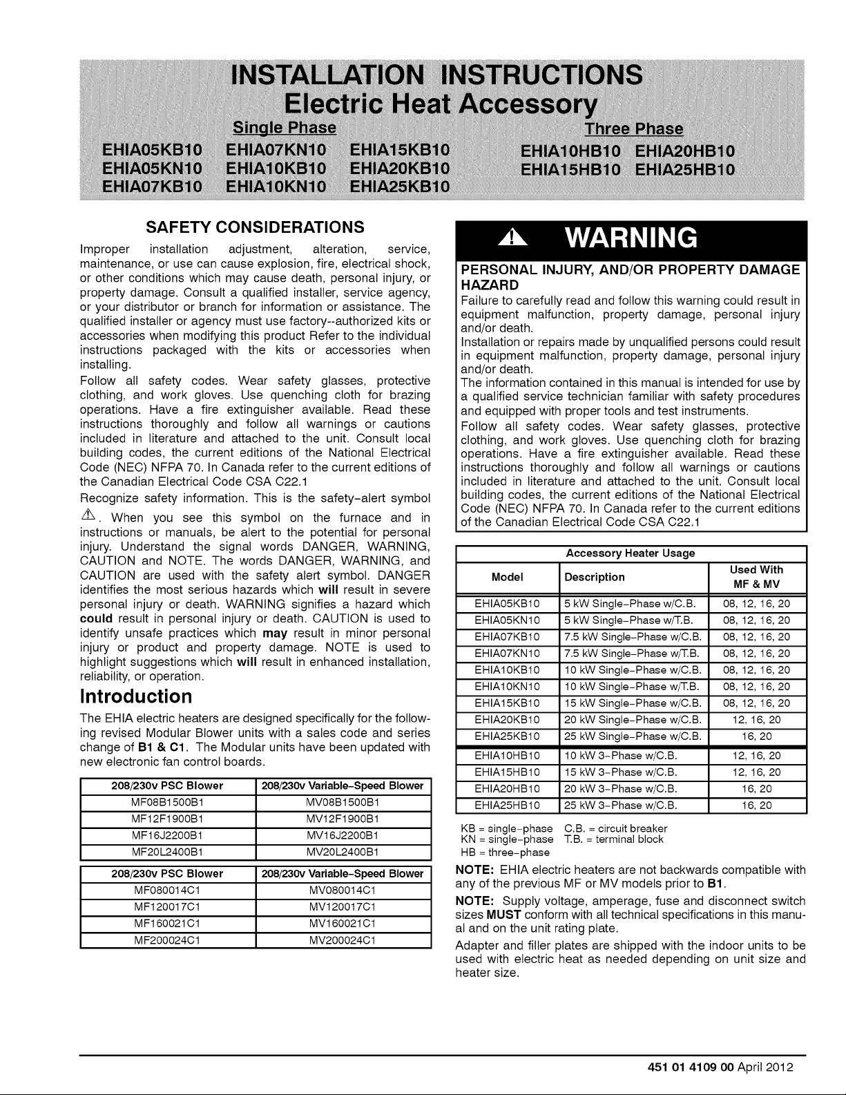
Accessory Heater Usage
Used With
Model Description MF & MV
EHIA05KB10 5 kW Single-Phase w/C.B. 08, 12, 16, 20
EHIA05KNt0 5 kW Single-Phase w/T.B. 08, 12, 16, 20
EHIA07KB10 7.5 kW Single-Phase w/C.B. 08, 12, 16, 20
EHIA07KNt0 7.5 kW Single-Phase w/T.B. 08, 12, 16, 20
EHIA10KB10 10 kW Single-Phase w/C.B. 08, 12, 16, 20
EHIA10KNt0 10 kW Single-Phase w/T.B. 08, 12, 16, 20
EHIA15KB10 15 kW Single-Phase w/C.B. 08, 12, 16, 20
EHIA20KB10 20 kW Single-Phase w/C.B. 12, 16, 20
EHIA25KB10 25 kW Single-Phase w/C.B. 16, 20
EHIA10HB10 10 kW 3-Phase w/C.B. 12, 16, 20
EHIA15HB10 15 kW 3-Phase w/C.B. 12, 16, 20
EHIA20HB10 20 kW 3-Phase w/C.B. 16, 20
EHIA25HB10 25 kW 3-Phase w/C.B. 16, 20
KB= single-phase C.B. = circuit breaker
KN =single-phase T.B.= terminal block
HB =three-phase
NOTE: EHIA electric heaters are not backwards compatible with
any of the previous MF or MV models prior to B1.
NOTE: Supply voltage, amperage, fuse and disconnect switch
sizes MUST conform with all technical specifications in this manu-
al and on the unit rating plate.
Adapter and filler plates are shipped with the indoor units to be
used with electric heat as needed depending on unit size and
heater size.
451 01 4109 O0April 2012
Page 2
ELECTRICALSHOCK HAZARD
Failure to follow this warning could result in personal injury or
death.
Before installing, modifying, or servicing system, main
electrical disconnect switch must be in the OFF position and
install a lockout tag. There may be more than one electrical
supply to the furnace. Check accessories and cooling unit for
additional electrical supplies that must be shut off during
furnace servicing. Lockout and tag switch with a suitable
warning label. Verify proper operation after servicing.
1. Shut OFF electric power at unit disconnect switch or ser-
vice panel.
CUT HAZARD
Failure to follow this caution may result in personal injury.
Sheet metal parts may have sharp edges or burrs. Use care
and wear appropriate clothing, safety glasses and gloves when
handling parts and servicing furnaces.
2.
Remove the front panel from unit and locate adapter and fill-
er plates, with screws inside package.
3.
Attach adapter plate and filler plate to heater if required to
match opening in cabinet.
4.
Right Hand Airflow Application Only/Heaters with CB.
If indoor section is going to be used for right hand airflow,
the circuit breakers will have to be removed and rotated
180°, so the OFF position will be DOWN when the cabinet
is positioned on the right side. This isan NEC requirement.
DO ONE SET OF BREAKERS AT A TIME to make sure
wires are reconnected properly, Loosen terminal screws
on the wires and gently pull wires back from breaker. Re-
move screws securing breaker and rotate 180°,then recon-
nect wires to breaker. Proper torque for terminal screws is
35 inch pounds.
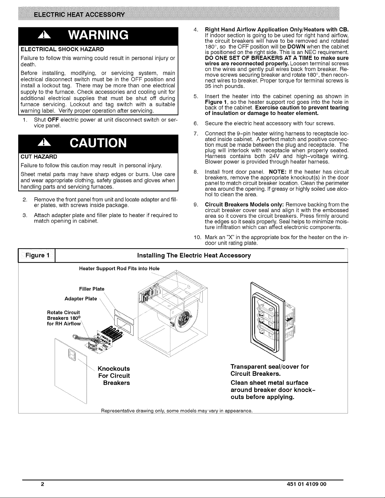
5.
Insert the heater into the cabinet opening as shown in
Figure 1, so the heater support rod goes into the hole in
back of the cabinet. Exercise caution to prevent tearing
of insulation or damage to heater element,
8.
Secure the electric heat accessory with four screws.
7.
Connect the 9-pin heater wiring harness to receptacle loc-
ated inside cabinet. A perfect match and positive connec-
tion must be made between the plug and receptacle. The
plug will interlock with receptacle when properly seated.
Harness contains both 24V and high-voltage wiring.
Blower power is provided through heater harness.
8.
Install front door panel. NOTE: If the heater has circuit
breakers, remove the appropriate knockout(s) in the door
panel to match circuit breaker location. Clean the perimeter
area around the opening. If greasy or highly soiled use alco-
hol to clean the area.
9.
Circuit Breakers Models only: Remove backing from the
circuit breaker cover seal and align it with the embossed
area so it covers the circuit breakers. Press firmly around
the edges so itseals properly. Seal helps to minimize mois-
ture infiltration which can affect electronic components.
10. Mark an "X" in the appropriate box for the heater on the in-
door unit rating plate.
Figure 1Jl Installing The Electric Heat
Heater Support RodFits into Hole
Filler Plate
Adapter Plate \
Rotate Circuit
Breakers 1800
for RHAirflow \
• \\
\,
Knockouts
For Circuit
Breakers
Representative drawin,q only, some models may vary in appearance.
Accessory
Transparent seal/cover for
Circuit Breakers.
Clean sheet metal surface
around breaker door knock-
outs before applying.
2 451 01 4109 00
Page 3
Wiring
All line voltage connections and ground connections MUST be
made with copper wire.
The power supply wiring MUST have overcurrent protection. This
can be either fuses or circuit breakers. The maximum size for the
overcurrent protection is shown in the column labeled "Max. Fuse
or NEC HACR Breaker (Amps)" inthe Electrical Data Table or on
the unit rating plate.
Connect supply voltage wires to the Circuit Breakers on the heater
or to the terminal block on the heater. Power for the blower motor is
supplied through the connector from the heater to the control
board.
Grounding
Permanently ground the electric heat accessory in accordance
with local codes and ordinances and in the United States with Na-
tional Electrical Code ANSI/NFPA70-2011 or current edition. Use
a copper conductor of the appropriate size from the electric heat
accessory ground lug, to a grounding lug on the circuit breaker
panel. On models with more than one circuit, a separate copper
ground wire MUST be connected for each circuit.
ELECTRICAL SHOCK HAZARD
Failure follow this warning could result in personal injury
or death.
The unit cabinet must have an uninterrupted or unbroken
ground to minimize personal injury if an electrical fault
should occur. The ground may consist of electrical sire
or metal conduit when installed in accordance with
existing electrical codes.
Heater Staging
The electric heater elements and modular blower controls are
factory circuited for single-stage electric heat operation. Refer to
Electric Heat Staging Table A-1 for all available heaters. On larger
heaters the electric heat can be staged (1st & 2nd and/or 3 rd) via
the indoor wall thermostat, or by using an accessory ODTS (out-
door thermostat temperature switch). Controlled heater staging
may satisfy requirements imposed by some electric utilities. Re-
fer to Table A-2 for two-stage capable heaters and Table A-3 for
three-stage capable heaters. Refer to the indoor modular install-
Table A Electric Heat Staging
A-1
Single-Stage Operation (no staging,
all electric heat together)
EHIA05KB / KN
EHIA07KB / KN
Single-Phase
Three-Phase
NOTE: KB is single-phase with circuit breaker.
KN is single-phase with terminal block (non-breaker).
HB is three-phase with circuit breaker.
EHIA10KB / KN
EHIA15KB
EHIA20KB
EHIA25KB
EHIAIOHB
EHIA15HB
EHIA20HB
EHIA25HB
ation instructions for suggested low-voltage control wiring regard-
ing staging.
Rectifier and Time Delay Boards
Each heater element is controlled by a relay mounted on the heat-
er panel. The relay has a 24V DO coil. Each relay has a small recti-
fier board attached directly to the relay coil terminals. The rectifier
board converts incoming 24V AC control signal to DC. Some
heaters may have up to three relays. Both the second and third
(relay) rectifier boards have a built-in R2 jumper time-delay fea-
ture. When the jumper is uncut, the time delay allows the second
stage heat to be energized approximately five (5) seconds after
the first stage. On 20kW and 25kW heaters models (table A-3),
the third-stage relay R2 jumper is factory cut. This provides an
eight (8) second delay after first stage relay closes.
Air Flow
Air flow requirements are different between MF and MV. Refer to
MF and MV Installation Instructions for airflow set-up information.
Temperature Rise Check
Temperature rise is the difference between the supply and return
air temperatures.
NOTE: The temperature rise can be adjusted by changing the
heating speed tap at the unit's blower terminal block. Refer to the
unit's Installation Instructions for airflow information.
A temperature rise greater than 60°F (33.300) is not recom-
mended,
1. To check the temperature rise through the unit, place ther-
mometers in the supply and return air ducts as close to the
unit as possible,avoiding direct radiant heat from the heater
elements.
2. Open ALL registers and duct dampers.
3. Set thermostat Heat-Cool selector to HEAT.
4. Set the thermostat temperature setting as high as it will go.
5. Turn electric power ON.
6. Operate unitAT LEAST 5 minutes, then check temperature
rise.
NOTE: The maximum outlet air temperature for all models is
200°F (93.3°C).
7. Set thermostat to normal temperature setting.
8. Turn electric power OFF.
9. Be sure to seat all holes in ducts if any were created during
this process.
A-2 A-3
Two-Stage Capable Three-Stage Capable
EHIA15KB
EHIA20KB
EHIA25KB
EHIA10HB
EHIA15HB
EHIA20HB
EHIA25HB
EHIA25KB10
EHIA20HB
EHIA25HB
451 01 4109 O0 3
Page 4
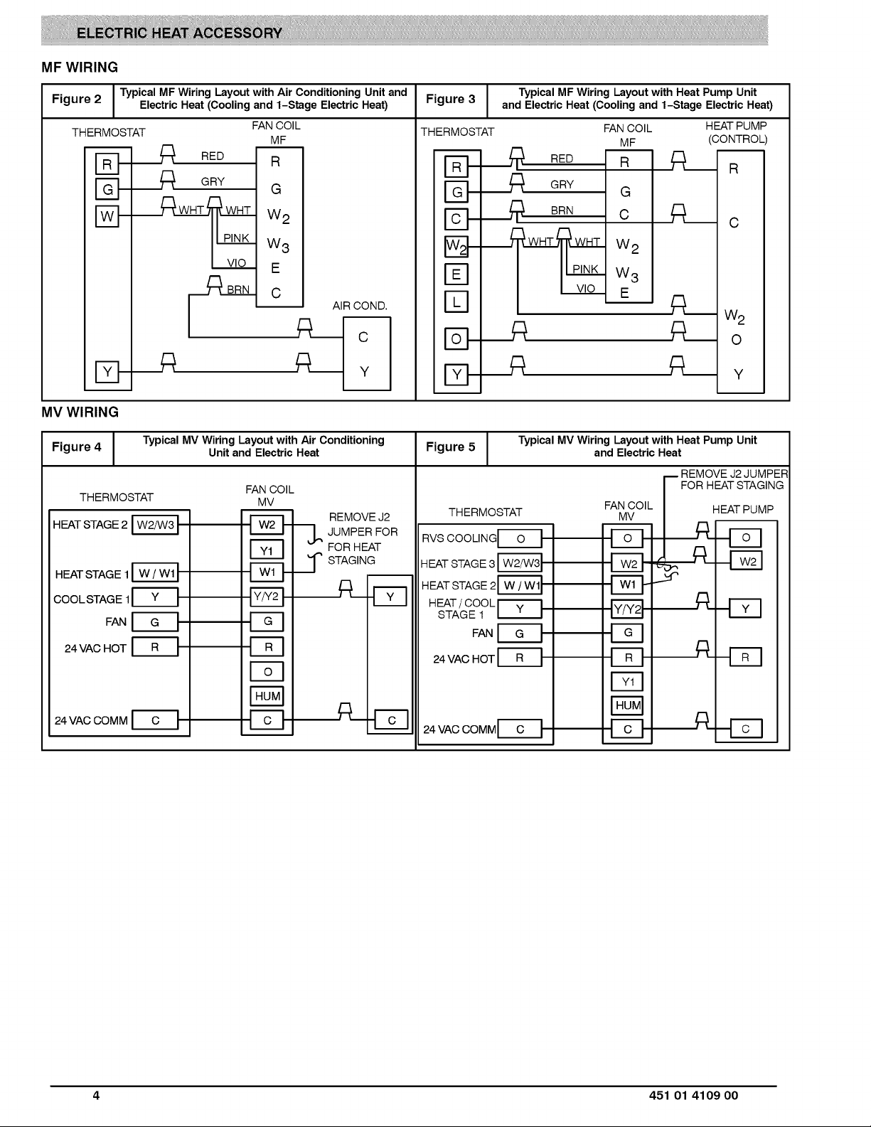
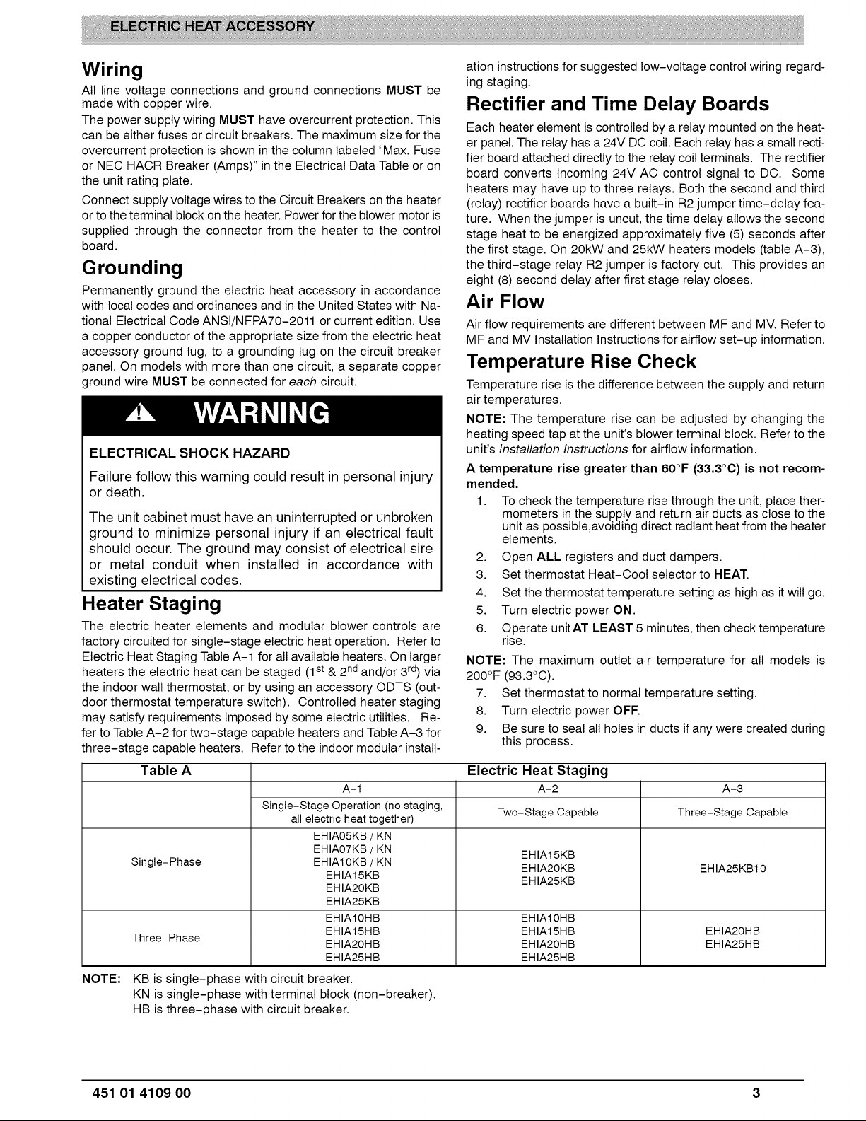
MFWIRING
Figure 2 Electric Heat (Cooling and 1-Stage Electric Heat) Figure 3 and Electric Heat (Cooling and 1-Stage Electric Heat)
MV WIRING
Figure 4 Typical MV Wiring Layout with Air Conditioning Typical MV Wiring Layout with Heat Pump Unit
HEAT STAGE 2
HEAT STAGE 1
COOL STAGE 1
24 VAC HOT
I Typical MF Wiring Layout with Air Conditioning Unit and Typical MF Wiring Layout with Heat Pump Unit
THERMOSTAT THERMOSTAT
m
D
D
RED
._ GRY
FAN COIL
MF
R
G
W2
W3
E
AIR COND.
m
N-
IN-
IN-
N-
%
K]
RED
_/_ GRY
BRN
FAN COIL
MF
R
G
C
W2
W 3
,E ,
IN-
THERMOSTAT
FAN
A__
Unit and Electric Heat Figure 5 and Electric Heat
FAN COIL
MV
REMOVE J2
F_q
"---_ JUMPER FOR
FOR HEAT
..._ STAGING
RVS COOLINGI--O_I
HEAT STAGE 3
HEAT STAGE 2_
HEAT / COOL I_v'_l
STAGE 1 I ' I
24 VAC HOT F_I
_A _q__
THERMOSTAT MV
FAN COIL
E_
FAN
,_q
,_q
HEAT PUMP
(CONTROL)
R
C
W2
O
Y
-- REMOVE J2 JUMPEF
FOR HEAT STAGING
HEAT PUMP
_-E3
_-EB
A-E_
Fq
F_
24 VAC COMM
24 VAC COMM F_I
,_q
_-E3
4 451 01 4109 O0
Page 5

TECHNICAL DATA (MF only) Single Phase with Circuit Breaker
Heater
Model
EHIA05KB10
EHIA07KB10
EHIA10KB10
EHIA15KB10
EHIA20KB10
EHIA25KB10
Supply Heat- Heat kW Per Circuit kW Per Heater Motor Total Circuit Device # of Wire Max. # of Min
Nom. Supply Heater Max FLA Min Protective 75 0C. Copper Wire
Volt- BTUH KW Element No. Circuit AMPS. AMPS. AMPS. Ampacity (AMPS.) Wires Size Length (Ft) Wires Size
240 16378 4.8 4.8
208 12283 3.6 3.6
240 24567 7.2 3.6
208 18425 5.4 2.7
240 32756 9.6 4.8
208 24567 7.2 3.6
240 49134 14.4 4.8
Single 4.8 20.0 6 26.0 32.5 35 2 8 113 1 10
Single 3.6 17.3 6 23.3 29.1 30 2 10 118 1 10
Single 7.2 30.0 6 36.0 45.0 45 2 8 81 1 10
Single 5.4 26.0 6 32.0 40.0 40 2 8 92 1 10
Single 9.6 40.0 6 46.0 57.5 60 2 6 101 1 10
Single 7.2 34.6 6 40.6 50.8 60 2 6 115 1 10
Single 14.4 60.0 6 66.0 82.5 90 2 4 113 1 8
Mult. 1 9.6 40.0 6 46.0 57.5 60 2 6 101 1 10
Mult. 2 4.8 20.0 0 20.0 25.0 25 2 10 95 1 10
208 36851 10.8 3.6
Single 10.8 51.9 6 57.9 72.4 80 2 4 128 1 8
Mult. 1 7.2 34.6 6 40.6 50.8 60 2 6 115 1 10
Mult. 2 3.6 17.3 0 17.3 21.6 25 2 10 109 1 10
240 65513 19.2 4.8
Single 19.2 80.0 6 86.0 107.5 110 2 2 137 1 6
Mult. 1 9.6 40.0 6 46.0 57.5 60 2 6 101 1 10
Mult. 2 9.6 40.0 0 40.0 50.0 50 2 8 73 1 10
208 49134 14.4 3.6
Single 14.4 69.2 6 75.2 94.0 100 2 3 124 1 10
Mult. 1 7.2 34.6 6 40.6 50.8 60 2 6 115 1 10
Mult. 2 7.2 34.6 0 34.6 43.3 45 2 8 85 1 10
240 81891 24 4.8
Single 24 100.0 6 106.0 132.5 150 2 1/0 177 1 6
Mult. 1 9.6 40.0 6 46.0 57.5 60 2 6 102 1 10
Mult. 2 9.6 40.0 0 40.0 50.0 50 2 8 74 1 10
Mult. 3 4.8 20.0 0 20.0 25.0 25 2 12 60 1 10
208 61418 18 3.6
Single 18 86.5 6 92.5 115.7 125 2 1 161 1 6
Mult. 1 7.2 34.7 6 40.7 50.8 60 2 6 104 1 10
Mult. 2 7.2 34.7 0 34.7 43.3 45 2 8 77 1 10
Mult. 3 3.6 17.3 0 17.3 21.7 25 2 12 62 1 10
Maximum Recommended**
MCA Overcur- SupplyWire Ground
TECHNICAL DATA (MF only) Single-Phase with Terminal Block
Heater
Model
EHIA05KN10
EHIA07KN10
EHIA10KN10
Supply Heat- Heat kW Per Circuit kW Per Heater M_or Total Circuit
Nom. Supply Heater Max FLA Min
Volt- BTUH KW Element
240 16378 4.8 4.8
208 12283 3.6 3.6
240 24567 7.2 3.6
208 18425 5.4 2.7
240 32756 9.6 4.8
208 24567 7.2 3.6
No. Circuit AMPS. AMPS. AMPS. Ampacity (AMPS.) Wires Size Length (Ft)
Single 4.8 20.0 6 26.0 32.5 35 2 8 113
Single 3.6 17.3 6 23.3 29.1 30 2 10 118
Single 7.2 30.0 6 36.0 45.0 45 2 8 81
Single 5.4 26.0 6 32.0 40.0 40 2 8 92
Single 9.6 40.0 6 46.0 57.5 60 2 6 101
Single 7.2 34.6 6 40.6 50.8 60 2 6 115
TECHNICAL DATA (MF only) Three Phase with Circuit Breaker
Heater
Supply Heat- Heat kW Per Circuit kW Per Heater Motor Total Circuit
Model
EHIA10HB10
EHIA15HB10
EHIA20HB10
EHIA25HB10
Conversion: 1 foot = .3048 meters
** Must conform to local building codes and national standards
USA: National Electrical Code (NEC)ANSI/NFPA 70-2011
CANADA: Canadian Electrical Code CSA C22.1
Nom. Supply Heater Max FLA Min
Volt- BTUH KW Element
240 32756 9.6 3.2
208 24567 7.2 2.4
240 49134 14.4 4.8
208 36851 10.8 3.6
240 65513 19.2 3.2
No,
Circuit AMPS. AMPS. AMPS. Ampacity (AMPS.) Wires Size Length (Ft)
Single 9.6 23.1 6
Single 7.2 20.0 6
Single 14.4 34.7 6
Single 10.8 30.0 6
Single 19.2 46.2 6
Mult. 1 6.4 15.4 6
Mult. 2 12.8 30.8 0
208 49134 14.4 2.4
Single 14.4 40.0 6
Mult. 1 4.8 13.3 6
Mult. 2 9.6 26.7 0
240 81891 24 4
Single 24 57.8 6
Mult. 1 8 19.3 6
Mult. 2 16 38.5 0
208 61418 18
Single 18 50.0 6
Mult. 1 6 16.7 6
Mult. 2 12 33.3 0
29.1 36.4 40 3 8
26.0 32.5 35 3 8
40.7 50.9 60 3 6
36.0 45.0 45 3 8
52.2 65.3 70 3 4
21.4 26.8 30 3 10
30.8 38.5 40 3 8
46.0 57.5 60 3 6
19.3 24.2 30 3 10
26.7 33.3 35 3 8
63.8 79.8 80 3 4
25.3 31.6 35 3 8
38.5 48.2 50 3 8
56.0 70.0 70 3 4
22.7 28.3 30 3 10
33.3 41.7 45 3 8
MCA
MCA
Maximum Recommended**
Overcur- SupplyWire
Protective 75 0C. Copper
Device # of Wire Max.
Maximum
Recommended**
Overcur- SupplyWire
Protective 75 0C. Copper
Device # of Wire Max.
117 1 10
131 1 10
132 1 8
94 1 10
165 1 8
102 1 10
110 1 10
117 1 8
113 1 10
127 1 10
135 1 8
134 1 10
88 1 10
153 1 8
96 1 10
102 1 10
Ground
Wire
# of Min
Wires Size
1 10
1 10
1 10
1 10
1 10
1 10
Ground
Wire
# of Min
Wires Size
451 01 4109 O0 5
Page 6

TECHNICAL DATA (MV only) Single Phase with Circuit Breaker
Nom. Supply Heater Max FLA Min Protective 75 0C. Copper Wire
Heater
Model
EHIA05KB10
EHIA07KB10
EHIA10KB10
EHIA15KB10
EHIA20KB10
EHIA25KB10
Supply Heat- Heat kW Per Circuit kW Per Heater Motor Total Circuit Device # of Wire Max. # of Min
Volt- BTuH KW Element No. Circuit AMP& AMP& AMP& Ampacity (AMP&) Wires Size Length (Ft) Wires Size
240 16378 4.8 4.8 Single 4.8 20.0 7.3 27.3 34.1 35 2 8 108 1 10
208 12283 3.6 3.6 Single 3.6 17.3 7.3 24.6 30.8 35 2 8 119 1 10
240 24567 7.2 3.6 Single 7.2 30.0 7.3 37.3 46.6 50 2 8 79 1 10
208 18425 5.4 2.7 Single 5.4 26.0 7.3 33.3 41.6 45 2 8 88 1 10
240 32756 9.6 4.8 Single 9.6 40.0 7.3 47.3 59.1 60 2 6 99 1 10
208 24567 7.2 3.6 Single 7.2 34.6 7.3 41.9 52.4 60 2 6 111 1 10
240 49134 14.4 4.8 Single 14.4 60.0 7.3 67.3 84.1 90 2 4 110 1 8
Mult. 1 9.6 40.0 7.3 47.3 59.1 60 2 6 99 1 10
Mult. 2 4.8 20.0 0 20.0 25.0 25 2 10 95 1 10
208 36851 10.8 3.6 Single 10.8 51.9 7.3 59.2 74.0 80 2 4 126 1 8
Mult. 1 7.2 34.6 7.3 41.9 52.4 60 2 6 111 1 10
Mult. 2 3.6 17.3 0 17.3 21.6 25 2 10 109 1 10
240 65513 19.2 4.8 Single 19.2 80.0 7.3 87.3 109.1 110 2 2 135 1 6
Mult. 1 9.6 40.0 7.3 47.3 59.1 60 2 6 99 1 10
Mult. 2 9.6 40.0 0 40.0 50.0 50 2 8 73 1 10
208 49134 14.4 3.6 Single 14.4 69.2 7.3 76.5 95.7 10O 2 3 122 1 6
Mult. 1 7.2 34.6 7.3 41.9 52.4 60 2 6 111 1 10
Mult. 2 7.2 34.6 0 34.6 43.3 45 2 8 85 1 10
240 81891 24 4.8 Single 24 100.0 7.3 107.3 134.1 150 2 10 175 1 6
Mult. 1 9.6 40.0 6.0 46.0 57.5 60 2 6 102 1 10
Mult. 2 9.6 40.0 0 40.0 50.0 50 2 8 74 1 10
Mult. 3 4.8 20.0 0 20.0 25.0 25 2 12 60 1 10
208 61418 18 3.6 Single 18 86.5 7.3 93.8 117.3 125 2 1 159 1 6
Mult. 1 7.2 34.7 6.0 40.7 50.8 60 2 6 104 1 10
Mult. 2 7.2 34.7 0 34.7 43.3 45 2 8 77 1 10
Mult. 3 3.6 17.3 0 17.3 21.7 25 2 12 62 1 10
Maximum Recommended*_
MCA Overcurrent SupplyWire Ground
TECHNICAL DATA (MV only) Single-Phase with Terminal Block
Heater
Model Volt- BTUH KW Element
EHIA05KN10
EHIA07KN10
EHIA10KN10
Supply Heat- Heat kWPer Circuit kWPer Heater Motor Total Circuit Device # of Wire Max.
Nom. Supply Heater Max FLA Min Protective 750 C. Copper
240 16378 4.8 4.8
208 12283 3.6 3.6
240 24567 7.2 3.6
208 18425 5.4 2.7
240 32756 9.6 4.8
208 24567 7.2 3.6
No. Circuit AMP& AMP& AMP& Ampacity (AMP&) Wire Size Length (Ft)
Single 4.8 20.0 7.3 27.3 34.1 35 2 8 108
Single 3.6 17.3 7.3 24.6 30.8 35 2 8 119
Single 7.2 30.0 7.3 37.3 46.6 50 2 8 79
Single 5.4 26.0 7.3 33.3 41.6 45 2 8 88
Single 9.6 40.0 7.3 47.3 59.1 60 2 6 99
Single 7.2 34.6 7.3 41.9 52.4 60 2 6 111
TECHNICAL DATA (MV only) Three-Phase with Circuit Breaker
Heater
Model
EHIA10HB10
EHIA15HB10
EHIA20HB10
EHIA25HB10
Supply Heat- Heat kW Per Circuit kW Per Heater Motor Total Circuit
Conversion: 1 foot = .3048 meters
** Must conform to local building codes and national standards
USA: National Electrical Code (NEC) ANSI/NFPA 70-2011
CANADA: Canadian Electrical Code CSA C22.1
Nom. Supply Heater Max FLA Min
Volt- B:rUH KW Element
240 32756 9.6 3.2
208 24567 7.2 2.4
240 49134 14.4 4.8
208 36851 10.8 3.6
240 65513 19.2 3.2
208 49134 14.4 2.4
240 81891 24 4
208 61418 18
No,
Single 9.6 23.1
Single 7.2 20.0
Single 14.4 34.7
Single 10.8 30.0
Single 19.2 46.2
Mult. 1 6.4 15.4
Mult. 2 12.8 30.8
Single 14.4 40.0
Mult. 1 4.8 13.3
Mult. 2 9.6 26.7
Single 24 57.8
Mult. 1 8 19.3
Mult. 2 16 38.5
Single 18 50.0
Mult. 1 6 16.7
Mult. 2 12 33.3
Circuit AMP& AMP& AMP& Ampacity (AMP&) Wires Size Length (Ft)
7.3 30.4 38.0 40 3 8
7.3 27.3 34.1 35 3 8
7.3 42.0 52.5 60 3 6
7.3 37.3 46.6 50 3 8
7.3 53.5 66.9 70 3 4
7.3 22.7 28.4 30 3 10
0 30.8 38.5 40 3 8
7.3 47.3 59.1 60 3 6
7.3 20.6 25.8 30 3 10
0 26.7 33.3 35 3 8
7.3 65.1 81.4 90 3 4
7.3 26.6 33.2 35 3 8
0 38.5 48.2 50 3 8
7.3 57.3 71.7 80 3 4
7.3 24.0 30.0 30 3 10
0 33.3 41.7 45 3 8
Maximum
MCA Overcurrent SupplyWire
Maximum
MCA
Overcur- SupplyWire
Protective 75 0C. Copper
Device # of Wire Max.
Recommended**
Recommended*"*
Ground
Wire
# of Min
Wires Size
1 10
1 10
1 10
1 10
1 10
1 10
Ground
Wire
# of Min
Wires Size
112 1 10
125 1 10
128 1 10
91 1 10
161 1 8
96 1 10
110 1 10
114 1 10
106 1 10
127 1 10
132 1 8
128 1 10
88 1 10
150 1 8
91 1 10
102 1 10
6 451 O14109 OO
Page 7

HEATER STAGING (MF & MV)
Single-Phase
ELECTRIC HEATER
EHIA05KB10
EHIA07KB10
EHIA10KB10
EHIA15KB10
EHIA20KB10
EHIA25KB10
VOLTAGE
208-240/1/60
208-240/1/60
208-240/1/60
208-240/1/60
208-240/1/60
208-240/1/60
TOTAL HEAT KW 18t STAGE KW (Wl)
208V 240V
3.6 4.8
5.4 7.2
7.2 9.6
10.8 14.4
14.4 19.2
18 24
208V 240V
3.6 4.8
5.4 7.2
7.2 9.6
7.2 9.6
7.2 9.6
7.2 9.6
2nd STAGE KW(W2)
240V208V
3.6
7.2
10.8
4.8
9.6
14.4
EHIA05KN10
EHIA07KN10
EHIA10KN10
208-240/1/60
208-240/1/60
208-240/1/60
3.6 4.8
5.4 7.2
7.2 9.6
3.6 4.8
5.4 7.2
7.2 9.6
Three-Phase
ELECTRIC HEATER
EHIA10HB10
EHIA15HB10
EHIA20HB10
EHIA25HB10
VOLTAGE
208-240/3/60
208-240/3/60
208-240/3/60
208-240/3/60
TOTAL HEAT KW
208v 240v
7.2 9.6
10.8 14.4
14.4 19.2
18 24
18t STAGE KW (Wl)
208v 240v
7.2 9.6
10.8 14.4
4.8 6.4
6 8
2nd STAGE KW (W2)
208v 240v
9.6
12
ELECTRIC HEATER STATIC PRESSURE DROP - ESP IN WC (MF & MV)
Single-Phase
CFM EHIA05 EHIA07 EHIA10 EHIA15 EHIA20 EHIA25
600 0.01 0.01 0.01
700 0.01 0.01 0.01
800 0.01 0.01 0.01 0.01 -
900 0.01 0.01 0.01 0.01 -
1000 0.01 0.01 0.01 0.01 0.02 -
1100 0.01 0.01 0.01 0.02 0.02 -
1200 0.01 0.01 0.01 0.02 0.02 -
1300 0.01 0.02 0.02 0.02 0.02 -
1400 0.01 0.02 0.02 0.02 0.03 0.03
1500 0.01 0.02 0.02 0.02 0.03 0.04
1600 0.01 0.02 0.02 0.03 0.03 0.04
1700 0.01 0.02 0.02 0.03 0.03 0.04
1800 0.01 0.02 0.02 0.03 0.04 0.04
1900 0.01 0.02 0.02 0.03 0.04 0.05
2000 0.01 0.02 0.02 0.03 0.04 0.05
Three-Phase
CFM - EHIA10 EHIA15 EHIA20 EHIA25
600 - 0.01 -
700 - 0.01 -
800 - 0.01 0.01 -
900 - 0.01 0.01 -
1000 - 0.01 0.01 0.02 -
1100 - 0.01 0.02 0.02 -
1200 - 0.01 0.02 0.02 -
1300 - 0.02 0.02 0.02 -
1400 - 0.02 0.02 0.03 0.03
1500 - 0.02 0.02 0.03 0.04
1600 - 0.02 0.03 0.03 0.04
1700 - 0.02 0.03 0.03 0.04
1800 - 0.02 0.03 0.04 0.04
1900 - 0.02 0.03 0.04 0.05
2000 - 0.02 0.03 0.04 0.05
12.8
16
451 01 4109 O0 7
Page 8

WIRING DIAGRAM FOR SINGLE-PHASE HEAT ACCESSORIES WITH CIRCUIT BREAKER
EHIA05KB10
r
SCHEMATIC DIAGRAM SINGLE SUPPLY CIRCUIT )
ELD OWERW,R,.G
SEE RATING PLATE
FOR VOLTS AND HERTZ
| SEE NOTE #1
_GND
HEATER VA: 1.7
DISCONNECT PER NEC
COMPONENT ARRANGEMENT )
.......
HTR1
9
_i °'
TF1 HTR1 LS1 n.- RELAY1
YE............._L
YEL BLU BLK
BLK
RELAY1
22VDC COIL
EZ3
PLUGS $ $ WH RN
7 9 6 2 3 5 1
NOTES:
1. Use Copper Wire (75 ° Min) Only Between Disconnect Switch And Unit.
2. To Be Wired In Accordance With Nec And Local Codes.
3. If Any Of The Original Wire, As Supplied, Must Be Replaced, Use The Same
Or Equivalent Type Wire.
111002195 rev.1
\
CB CIRCUIT BREAKER
GND EQUIPMENT GROUND
HTR HEATER
41 LS
REC
TDR
TF
O
---)>---
_I Y _',
LEGEND
LIMIT SWITCH
RECTIFIER
TIME DELAY RECTIFIER
THERMAL FUSE
FIELD POWER WIRING
MARKED TERMINAL
PLUG AND RECEPTACLE
EHIA05KB10
EHIA07KB10 / EHIA10KB10
f
(- SCHEMATIC DIAGRAM SINGLE SUPPLY CIRCUIT )
FIELD I_OWER WIRING
SEE RATING PLATE
FOR VOLTS AND HERTZ
I SEE NOTE #1
_GND
E9
YEL TF2 HTR2 LS2 BLU RELAY1 BL-
YI:L I_LU 2 I_)\ r.
YEL_ TI;: *1 I-ITI_ "1 I_'1 RELAY1 >BLK
_ TT_,IF HT.R1 LSl BLU _LL /
_T RELAY1
YEL BLU BLK I REC I
I I I WH_RN
17 9 6 z ._ 5
k. •
PLUG _ XL/ _
NOTES:
1,
Use Copper Wire (75 ° Min) Only Between Disconnect Switch And Unit.
2.
To Be Wired In Accordance With Nec And Local Codes.
3.
If Any Of The Original Wire, As Supplied, Must Be Replaced, Use The Same
Or Equivalent Type Wire.
HEATER VA: 1.7
DISCONNECT PER NEC
>qd
x
111002197 rev.1
( COMPONENT ARRANGEMENT .)
.......
HTR2
iii I trl
\
CB
CIRCUIT BREAKER
GND
EQUIPMENT GROUND
HTR
HEATER
4 I LS
_ FIELD POWER WIRING
-_-_ PLUG AND RECEPTACLE
LIMIT SWITCH
REC
RECTIFIER
TDR
TIME DELAY RECTIFIER
TF
THERMAL FUSE
O MARKEDTERMINAL
EHIA07KB10 / EHIA10KB10
Io I
,ITI
L____J
LEGEND
,_-_@
8 451 01 4109 00
Page 9

EHIA15KB10
( SCHEMATIC DIAGRAM SINGLE SUPPLY CIRCUIT )
ELD OWER R,NG
SEE RATING PLATE
FOR VOLTS AND HERTZ
I SEE NOTE #1
_GND
HEATER VA: 3.4
DISCOINNECT PER NEC
COMPONENT ARRANGEMENT )
I1--1 I--
__7_.._j-- __Y_, ___
i i
Ea
RELAY2 =.----_
YEL TF3 HTR3 LS3 BL" RELAY2 BLK
Y_L .... ULU 2
YEL TF2 HTR2 LS2 BLU RELAY1 BLK
YEL #LU AY1 BLK
22VDC COIL
YEL BLU BLK I REC I
I I I WH_RN
"..1/ PLUG _ _, _/ '..1/
I 7 9 6 2 3
NOTES:
1. Use Copper Wire (75 ° Min) Only Between Disconnect Switch And Unit.
2. To Be Wired In Accordance With Nec And Local Codes.
3. If Any Of The Original Wire, As Supplied, Must Be Replaced, Use The Same
Or Equivalent Type Wire.
• I 111002198 rev.1 ,
I
PNK BRN
,1, +
5 4 I
kZ__!
CB CIRCUIT BREAKER
GND EQUIPMENT GROUND
HTR HEATER
LS LIMIT SWITCH
REC RECTIFIER
TDR TIME DELAY RECTIFIER
TF THERMAL FUSE
III FIELD POWER WIRING
O MARKED TERMINAL
"_'_ PLUG AND RECEPTACLE
RELAY1 r---_
LEGEND
EHIA15KB10
I O I
EHIA2OKBIO
r
(SCHEMATIC DIAGRAM SINGLE SUPPLY CIRCUIT )
I FIELD I_OWER WIIRING SEE RATING PLATE
FOR VOLTS AND HERTZ
HEATER VA: 3.4
DISCOINNECT PER NEC
IC,a
GND SEE NOTE #1
I YEL TF4 HTR4 LS4 BLU RELAY2 BL"
_ _//"TF3 HTR3 LS3 BLU
YEL TF2 HTR2 LS2 BL- RELAY1 BL"
YLL _LU 6 I_)\ r'
' I / RELAY1
YEL BLU BLK
I I I WH_RN
I 7 9 6 2 3
PLUG _ _J/ _
NOTES:
"N
PNK BRN
5 4 I
1. Use Copper Wire (75 ° Min) Only Between Disconnect Switch And Unit. TF
2. To Be Wired In Accordance With Nec And Local Codes. 11--
3. If Any Of The Original Wire, As Supplied, Must Be Replaced, Use The Same O
Or Equivalent Type Wire. _>_
• I 111002199 rev.1
RELAY1 RELAY2
22VDC COIL
COMPONENT ARRANGEMENT )
(1 ....... ,, .......
HTR2 HTR1
HTR4 HTR3
LEGEND
CB
CIRCUIT BREAKER
GND
EQUIPMENT GROUND
HTR
HEATER
LS
LIMIT SWITCH
REC
RECTIFIER
TDR
TIME DELAY RECTIFIER
THERMAL FUSE
FIELD POWER WIRING
MARKED TERMINAL
PLUG AND RECEPTACLE
EHIA20KB10
J
451 01 4109 O0 9
Page 10

EHIA25KB10
(SCHEMATIC DIAGRAM SINGLE SUPPLY CIRCUIT ) HEATER VA: 5.1
FIELD POWER WIRING SEE RATING PLATE DISCONNECT PER NEC
I I I I FOR VOLTS AND HERTZ I I I I
/ I--;Ik--II--4TI I--A-q I SEENOTE#1 _ I--4TI I--4TI /
.... HTR RELAY IB'K/
I YEL TF4 HTR4 LS4 BLU RELAY2 BLK I
YEL TF2 HTR2 LS2 BLU RELAY1 BLK
YcL B_ 6 I_)_ PNIK _IRN
YEL R T_F1 HTR1 LSl .... F_ELAYI_ 7 BLK RELAYS I
_Lu 2 _ 22REd'IlL I 2,vF%o"l
Y!, _- B!u B!K I--_
I I I WH_RN 1 VlO BRN
xJ/ PLUG _ _ _ x_ q/xJ,," xJ/
17 9 6 2 3 5 1 4 I
NOTES:
1. Use Copper Wire (75 ° Min) Only Between Disconnect Switch And Unit.
2. To Be Wired In Accordance With Nec And Local Codes.
3. If Any Of The Original Wire, As Supplied, Must Be Replaced, Use The Same
Or Equivalent Type Wire.
/
I 111002200 rev.1
I
COMPONENT ARRANGEMENT )
(" "] (" ";
HTR2 HTR1
HTR4 HTR3
HTR5
RELAY1 RELAY2 RELAY3
[____EC__I[__P__%_IL_P__%_I
LEGEND
CB CIRCUIT BREAKER
GND EQUIPMENT GROUND
HTR HEATER
LS LIMIT SWITCH
REC RECTIFIER
TDR TIME DELAY RECTIFIER
TF THERMAL FUSE
_ FIELD POWER WIRING
O MARKED TERMINAL
"_>-- PLUG AND RECEPTACLE
EHIA25KB10
10 451 01 410900
Page 11

WIRING DIAGRAM FOR SINGLE-PHASE HEAT ACCESSORIES WITH
TERMINAL BLOCK (NON-BREAKER)
EHIAO5KNIO
:SCHEMATIC DIAGRAM SINGLE SUPPLY CIRCUIT :)
I I SEE NOTE #1
IELD POWER WIRING SEE RATING PLATE DISCONNECT PER NEC
FOR VOLTS AND HERTZ
HEATER VA: 1.7
:COMPONENT ARRANGEMENT )
(- ........... ]
:QZ.......
HTR1
'
._ GND
rI---Ii
_ I 0 I
v _ L:__J
TF1 HTR1 LS1 BL- RELAY1
YEI_ _ )_.._ _..£ _.
YEL BLU BLK I REC I
PLUGS $ $ WHTq;--7RN
7 9 6 2 3 5
NOTES:
1. Use Copper Wire (75 ° Min) Only Between Disconnect Switch And Unit.
2. To Be Wired In Accordance With Nec And Local Codes.
3. If Any Of The Original Wire, As Supplied, Must Be Replaced, Use The Same
Or Equivalent Type Wire.
• J
BLK
RELAY1
22VDC COIL
111002192 rev.1
1 41
TB
I I
LEGEND
GND EQUIPMENT GROUND
HTR HEATER
LS LIMIT SWITCH
REC RECTIFIER
TB TERMINAL BLOCK
TDR TIME DELAY RECTIFIER
TF THERMAL FUSE
_ FIELD POWER WIRING
O MARKED TERMINAL
.i>>._ PLUG AND RECEPTACLE
EHIA05KN10
EHIA07KN10 / EHIA10KN10
(, SCHEMATIC DIAGRAM SINGLE SUPPLY CIRCUIT ) HEATER VA: 117
I FIELD POWER WIRING SEE RATING PLATE DISCONNECT PER NEC
I I SEE NOTE #1
FOR VOLTS AND HERTZ
/
, i
G.D
YEL TF2 HTR2 LS2 BLU RELAY1 BL"
Y_ _Lu 2 I'_\ r"
YEL_ T_ _4TP_ I_ RELAYI >BLK
I RELAY1
YEL BLU BLK
I I / WH_RN
I 7 9 6 2 3 5
PLUG _ ",,I,," ",,I,,"
NOTES:
1. Use Copper Wire (75 ° Min) Only Between Disconnect Switch And Unit.
2. To Be Wired In Accordance With Nec And Local Codes.
3. If Any Of The Original Wire, As Supplied, Must Be Replaced, Use The Same
Or Equivalent Type Wire.
I 111002194 rev.1
i
:COMPONENT ARRANGEMENT )
(- ........... .)
._j I WI
w I rrl
\
GND EQUIPMENT GROUND
HTR HEATER
LS LIMIT SWITCH
41
REC RECTIFIER
TB TERMINAL BLOCK
TDR TIME DELAY RECTIFIER
TF THERMAL FUSE
_ FIELD POWER WIRING
0 MARKED TERMINAL
"_>'_ PLUG AND RECEPTACLE
EHIA07KN10 / EHIA10KN10
HTR1
HTR2
LEGEND
iI---Ii
i o I
L:__J
TB
i i
I I
,_-_@
451 01 4109 O0 11
Page 12

WIRING DIAGRAM FOR THREE-PHASE HEAT ACCESSORIES
EHIA10HB10 / EHIA15HB10
( SCHEMATIC DIAGRAM SINGLE SUPPLY CIRCUIT ) HEATER VA: 3.4
I FOR VOLTS AND HERTZ
ELD POWER WIRING SEE RATING PLATE
GND
_] SEE NOTE #1
BLK TF3 HTR3 LS3 BL" RELAY2 _.,
_LR .... _LU 2
RELAY1 . r. TF2 HTR2 LS2 _m.
2 Y=L OLU
• v=. TF1 HTR1 LS1 n... RELAY1 n, ..
YEL BLU BLK
DISCONNECT PER NE_._
cr E
__Go_,,
Y RELAY1
/
22VDC COIL
I I I WHTI_ IBRN PNK
17 9 6 2 3 5
PLUG ",,1/ ",,1/ ',,1/ ',,1/ ",.J/
NOTES:
1. Use Copper Wire (75 ° Min) Only Between Disconnect Switch And Unit.
2. To Be Wired In Accordance With Nec And Local Codes.
3. If Any Of The Original Wire, As Supplied, Must Be Replaced, Use The Same
Or Equivalent Type Wire.
4. 208/240V 3-Phase Heaters shown above.
I 111002202 rev.1
COMPONENT ARRANGEMENT )
1/-
I1--1 I--
I'-_ ' ' _?£-I
,._ 7_,__/,-- ,._Y,,_J __.,
RELAY2 ,-----,
i(::) I
kS__!
RELAY2
3dpLEGEND
c0
CIRCUIT BREAKER
BRN GND
4 I LS
III
"_>_ PLUG AND RECEPTACLE
EQUIPMENT GROUND
HEATER
HTR
LIMIT SWITCH
REC
RECTIFIER
TDR
TIME DELAY RECTIFIER
TF
THERMAL FUSE
FIELD POWER WIRING
0
MARKED TERMINAL
EHIA10HB10 / EHIA15HB10
RELAY1 ,-----,
ic) I
_ ¢i,,o,
%__J
3qb
J
EHIA20HB10 / EHIA25HB10
( SCHEMATIC DIAGRAM SINGLE SUPPLY CIRCUIT ) HEATER VA: 5.1 (COMPONENT ARRANGEMENT )
FIELD POWER WIRING SEE RATING PLATE DISCONNECT PER NEC fr-_--_\ t_--_\
I I I I FORVOLTSANDHERTZ | | | I '._ _fH,' '._b u £_.'
l _ _ _ | SEE NOTE#1 _ _ _ l ,----'-H-T-R'-2...... . ,-----H-T-R-1 ..... .
I_X)I I_X)I I_Y--,)l_ I_Y--,)l I_X)I I_X)I .- HTR2_ -. .- HTR3_ -.
I k IBLK_ T._F6 HTR6 LS6 _,. RELAYP'IBLU I// -- -- --
I1 IBLu_LS5_ ,HTR5 -TF5 _YELf_RE,LA, Y3 .... 1//
I I _u _ _1// RELAY1 RELAY2 RELAY3
I _ 2 _LI% AA,--O--f_ _ // RELAY2 I ..L ..L I I ..L ..L I I ..L ..L I
I "_ " "_ - _ ....... - I /I 22VDCCOIL I t T I I t t I I T t I
I k BLK LS3 HTR3 tF3 _._ RELAY2 _., J "1 I®GI I®@1 I® QI
I =_ o_ 6 F_---_I I _ rrl--_--01]rrl--_-ol]rh--_--01]
I ' BLU/ I _, .... • i_1 i_1 i_1
[ .... RELAY1 .... LS2 HTR2 TF2 _ J PNK BRN ,I REC ,I ,I TDR ,I ,I TDR ,I
I 2 _L - R_i/--_ELAY1 I 2=_,L ...... --" ..................
L v=, LS1 HTR1 TF1 _,, RELAY1 BLKI 22VDCCOIL I _ I _4. /rt_-I:Cklr_
|_ r__,/ [_-_-_ | [-[__u.._ CB CIRCUIT BREAKER
YEL BLU........... BLK \^tWT_'_'-_N I VlO. BRN. GND EQUIPMENT GROUND
"4/ PLUG -_/ x.]/ x.]/ x.]/ x_/ x_/ "..1/ HTR HEATER
I 7 9 6 2 3 5 1 4 I LS LIMIT SWITCH
NOTES: REC RECTIFIER
1. Use Copper Wire (75 ° Min) Only Between Disconnect Switch And Unit.
2. To Be Wired In Accordance With Nec And Local Codes.
3. If Any Of The Original Wire, As Supplied, Must Be Replaced, Use The Same
Or Equivalent Type Wire.
4. 208/240V 3-Phase Heaters shown above. I 111002204 rev.1
TDR TIME DELAY RECTIFIER
TF THERMAL FUSE
_ FIELD POWERWIRING
0 MARKED TERMINAL
"_'_ PLUG AND RECEPTACLE
EHIA20HB10 / EHIA25HB10
12 451 01 4109 00
Page 13

Replacement Parts
4
5
Representative drawing only, some models may vary in appearance.
KEY
NO.
1
Circuit Breaker, 25 Amp
DESCRIPTION
Circuit Breaker, 35 Amp
Circuit Breaker, 45 Amp
Circuit Breaker, 50 Amp
Circuit Breaker, 60 Amp
Circuit Breaker, 30 Amp, 3P
Circuit Breaker, 40 Amp, 3P
Circuit Breaker, 45 Amp, 3P
Circuit Breaker, 60 Amp, 3P
2 Lug, Ground
3 Rectifier Board
Rectifier Board
4 Limit, Thermal - L140-40F
Limit, Thermal - L145-40F
5 Thermal Cutoff
6 Relay
][ PARTS NOT SHOWN
][ I Circuit Breaker Seal
1-Phase 3-Phase
-r- -r- -r- -r- -r- -r- -r- -r- -r- -r- -r- -r- -r-
PART NO.
1082008
1082010
1082012
1082013
1082014
U.I U.I U.I U.I U.I U.I U.I U.I U.I U.I U.I U.I U.I
1 - 1
1
1
1 1
1 1 1 1
1083190
1084792
1 1 1
1084793
1080913
91590
1171780
1171906
1176270
1176271
1176269
1172506
11087843 I-I-I-11111111111111111111
1 1 1 1 1 1 2 2 3 1 1 2 2
1 1 1 1 1 1 1 1 1 1 1 1 1
1 1 2 1 1 2 2
4 5 6
1 22 1 223 336
1 2 2 1 2 2 3 4 5 3 3 6 6
1 1 1 1 1 1 2 2 3 2 2 3 3
1
1
1
451 01 4109 O0 13
 Loading...