

Page 1
INSTA LATION
INSTRUCTIONS
s
.//
/
/
Models
EF08B1500A1, A2
EF12F1900A
EF16J2200A
EF20N2600A
With
AMF001NHA
Accessory No Heat Kit
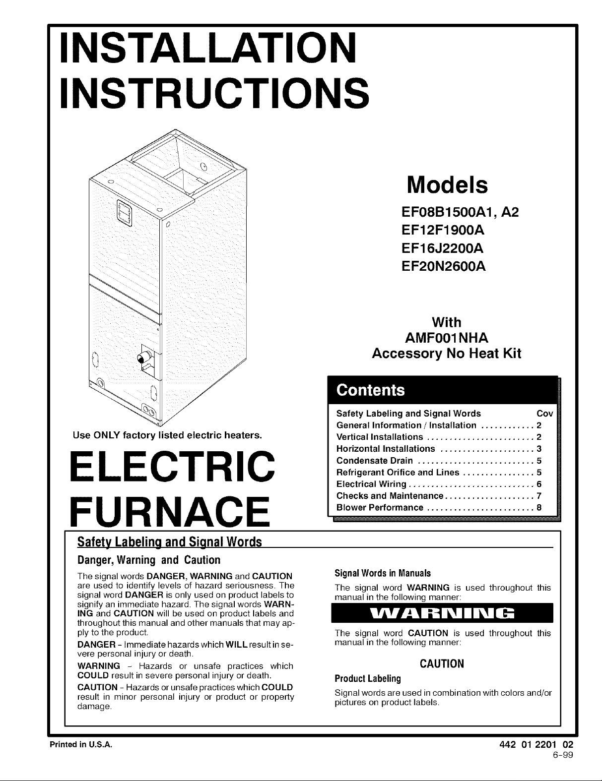
Use ONLY factor'
listed electric heaters.
ECTRIC
FURNACE
SafetyLabeling and SignalWords
Danger,Warning and Caution
The signal words DANGER, WARNING and CAUTION
are used to identify levels of hazard seriousness. The
signal word DANGER is only used on product labels to
signify an immediate hazard. The signal words WARN-
ING and CAUTION will be used on product labels and
throughout this manual and other manuals that may ap-
ply to the product.
DANGER - Immediate hazards which WILL result in se-
vere personal injury or death.
WARNING - Hazards or unsafe practices which
COULD result in severe personal injury or death.
CAUTION - Hazards or unsafe practices which COULD
result in minor personal injury or product or property
damage.
Safety Labeling and Signal Words Coy
General Information / Installation ............ 2
Vertical Installations ........................ 2
Horizontal Installations ..................... 3
Condensate Drain .......................... 5
Refrigerant Orifice and Lines ................ 5
Electrical Wiring ............................ 6
Checks and Maintenance .................... 7
Blower Performance ........................ 8
Signal Words in Manuals
The signal word WARNING is used throughout this
manual in the following manner:
The signal word CAUTION is used throughout this
manual in the following manner:
CAUTION
Product Labeling
Signal words are used incombination with colors and/or
pictures on product labels.
Printed in U.S.A. 442 01 2201 02
6-99
Page 2
_ Installation Instructions Electric Furnace I
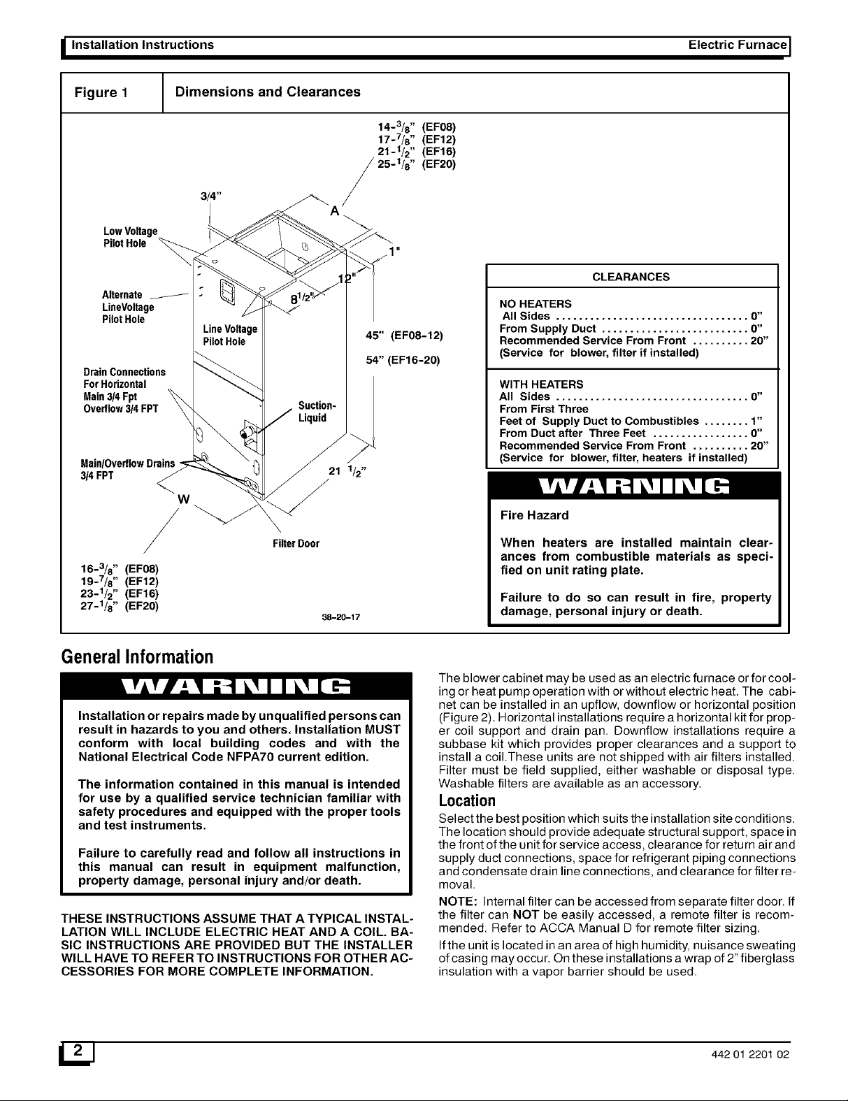
Figure 1 Dimensions and Clearances
14-3/8 " (EF08)
17-7/8 " (EF12)
21-1/2" (EF16)
25-1/8 " (EF20)
3/4"
LowVoltage
PilotH01e
CLEARANCES
Alternate
LineVoltage
PilotHole
DrainConnections
For Horizontal
Main3/4 Fpt
Overflow3/4 FPT
Main/OverflowDrains -
3/4 FPT
W
LineVoltage
PilotHole
45" (EF08-12)
54" (EF16-20)
Suction-
Liquid
NO HEATERS
All Sides .................................. O"
From Supply Duct .......................... 0"
Recommended Service From Front .......... 20"
(Service for blower, filter if installed)
WITH HEATERS
All Sides .................................. O"
From First Three
Feet of Supply Duct to Combustibles ........ 1"
From Duct after Three Feet ................. 0"
Recommended Service From Front .......... 20"
(Service for blower, filter, heaters if installed)
Fire Hazard
/
16-3/8 '' (EF08)
19-7/8 '' (EF12)
FilterDoor
23-1/2" (EF16)
27-1/8'' (EF20)
38-20-17
GeneralInformation
Installation or repairs made by unqualified persons can
result in hazards to you and others. Installation MUST
conform with local building codes and with the
National Electrical Code NFPA70 current edition.
The information contained in this manual is intended
for use by a qualified service technician familiar with
safety procedures and equipped with the proper tools
and test instruments.
Failure to carefully read and follow all instructions in
this manual can result in equipment malfunction,
property damage, personal injury and/or death.
THESE INSTRUCTIONS ASSUME THAT A TYPICAL INSTAL-
LATION WILL INCLUDE ELECTRIC HEAT AND A COIL. BA-
SIC INSTRUCTIONS ARE PROVIDED BUT THE INSTALLER
WILL HAVE TO REFER TO INSTRUCTIONS FOR OTHER AC-
CESSORIES FOR MORE COMPLETE INFORMATION.
When heaters are installed maintain clear-
ances from combustible materials as speci-
fied on unit rating plate.
Failure to do so can result in fire, property
damage, personal injury or death.
The blower cabinet may be used as an electric furnace or for cool-
ing or heat pump operation with or without electric heat. The cabi-
net can be installed in an upflow, downflow or horizontal position
(Figure 2). Horizontal installations require a horizontal kit for prop-
er coil support and drain pan. Downflow installations require a
subbase kit which provides proper clearances and a support to
install a coil.These units are not shipped with air filters installed.
Filter must be field supplied, either washable or disposal type.
Washable filters are available as an accessory.
Location
Select the best position which suits the installation site conditions.
The location should provide adequate structural support, space in
the front of the unit for service access, clearance for return air and
supply duct connections, space for refrigerant piping connections
and condensate drain line connections, and clearance for filter re-
moval.
NOTE: Internal filter can be accessed from separate filter door. If
the filter can NOT be easily accessed, a remote filter is recom-
mended. Refer to ACCA Manual D for remote filter sizing.
Ifthe unit is located in an area of high humidity, nuisance sweating
of casing may occur. On these installations a wrap of 2" fiberglass
insulation with a vapor barrier should be used.
442 01 2201 02
Page 3
I Electric Furnace Installation Instructions I
UpflowInstallations
The unit is ready to install in the upflow position without modifica-
tions.
The unit MUST be supported on the bottom ONLY and set on a
supporting frame or shelf. Use screws through the bottom to an-
chor to supporting frame.
DownflowInstallations
Refer to instructions with Subbase Kit.
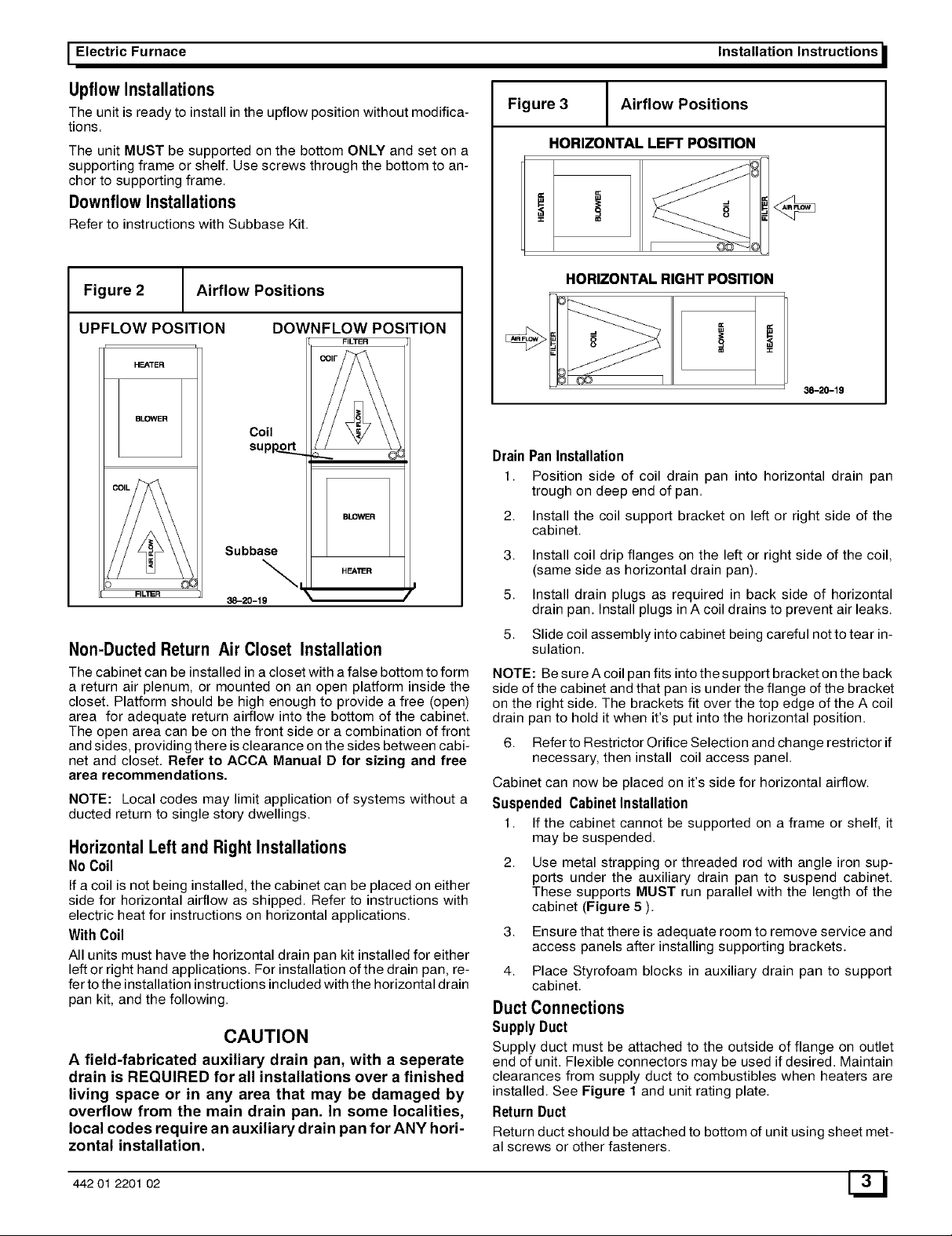
Figure 2 Airflow Positions
UPFLOW POSITION
HEATER
BLOWER
DOWNFLOW POSITION
FILTER
Coil
supop_._
Subbase
HF-_'_R
\ /
FILI_R
\,
38-20-19
Non-DuctedReturn Air Closet Installation
The cabinet can be installed in a closet with a false bottom to form
a return air plenum, or mounted on an open platform inside the
closet. Platform should be high enough to provide a free (open)
area for adequate return airflow into the bottom of the cabinet.
The open area can be on the front side or a combination of front
and sides, providing there is clearance on the sides between cabi-
net and closet. Refer to ACCA Manual D for sizing and free
area recommendations.
NOTE: Local codes may limit application of systems without a
ducted return to single story dwellings.
Horizontal Leftand Right Installations
No Coil
Ifa coil is not being installed, the cabinet can be placed on either
side for horizontal airflow as shipped. Refer to instructions with
electric heat for instructions on horizontal applications.
With Coil
All units must have the horizontal drain pan kit installed for either
left or right hand applications. For installation of the drain pan, re-
fer to the installation instructions included with the horizontal drain
pan kit, and the following.
CAUTION
A field-fabricated auxiliary drain pan, with a seperate
drain is REQUIRED for all installations over a finished
living space or in any area that may be damaged by
overflow from the main drain pan. In some localities,
local codes require an auxiliary drain pan for ANY hori-
zontal installation.
Figure 3 Airflow Positions
HORIZONTAL LEFT POSITION
HORIZONTAL RIGHT POSITION
,,=,
38-20-19
Drain Pan Installation
1. Position side of coil drain pan into horizontal drain pan
trough on deep end of pan.
2,
Install the coil support bracket on left or right side of the
cabinet.
3,
Install coil drip flanges on the left or right side of the coil,
(same side as horizontal drain pan).
5.
Install drain plugs as required in back side of horizontal
drain pan. Install plugs in A coil drains to prevent air leaks.
5.
Slide coil assembly into cabinet being careful not to tear in-
sulation.
NOTE: Be sure A coil pan fits into the support bracket on the back
side of the cabinet and that pan is under the flange of the bracket
on the right side. The brackets fit over the top edge of the A coil
drain pan to hold it when it's put into the horizontal position.
6. Refer to Restrictor Orifice Selection and change restrictor if
necessary, then install coil access panel.
Cabinet can now be placed on it's side for horizontal airflow.
Suspended Cabinet Installation
1. If the cabinet cannot be supported on a frame or shelf, it
may be suspended.
2,
Use metal strapping or threaded rod with angle iron sup-
ports under the auxiliary drain pan to suspend cabinet.
These supports MUST run parallel with the length of the
cabinet (Figure 5 ).
3,
Ensure that there is adequate room to remove service and
access panels after installing supporting brackets.
4.
Place Styrofoam blocks in auxiliary drain pan to support
cabinet.
DuctConnections
Supply Duct
Supply duct must be attached to the outside of flange on outlet
end of unit. Flexible connectors may be used if desired. Maintain
clearances from supply duct to combustibles when heaters are
installed. See Figure 1 and unit rating plate.
Return Duct
Return duct should be attached to bottom of unitusing sheet met-
al screws or other fasteners.
442 01 2201 02 W
Page 4
_ Installation Instructions
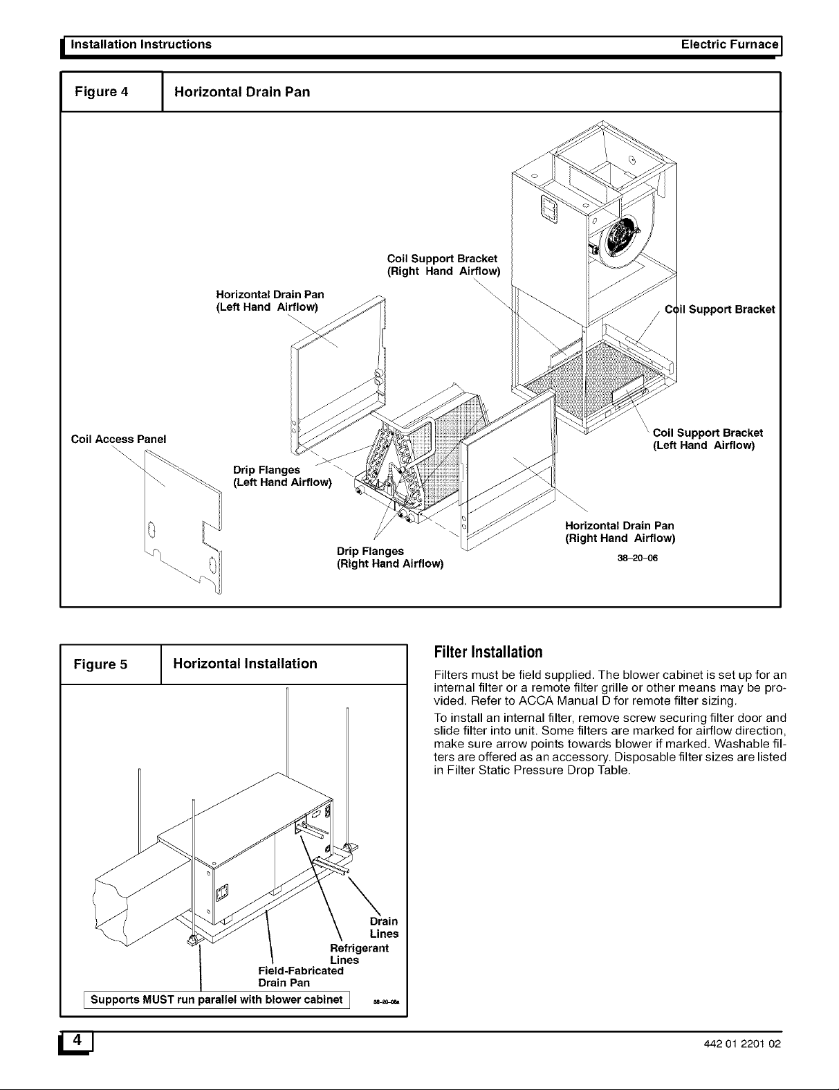
Figure 4 / Horizontal Drain Pan
1
Horizontal Drain Pan
(Left Hand Ai_ow)
Coil Support Bracket
(Right Hand Ai_w)
Electric Furnace I
\
il Support Bracket
Coil Access Panel
\
\
Drip Flanges
(Left Hand Airflow)
Figure 5 Horizontal Installation
Drip Flanges
(Right Hand Airflow)
Coil Support Bracket
(Left Hand Airflow)
Horizontal Drain Pan
(Right Hand Airflow)
38-20-06
FilterInstallation
Filters must be field supplied. The blower cabinet is set up for an
internal filter or a remote filter grille or other means may be pro-
vided. Refer to ACCA Manual D for remote filter sizing.
To install an internal filter, remove screw securing filter door and
slide filter into unit. Some filters are marked for airflow direction,
make sure arrow points towards blower if marked. Washable fil-
ters are offered as an accessory. Disposable filter sizes are listed
in Filter Static Pressure Drop Table.
Field-Fabricated
L Drain Pan
I Supports MUST run parallel with blowercabinet I =_=0_,
442 01 2201 02
Page 5

I Electric Furnace
CondensateDrain
Installation Instructions
The unit is provided with 3/4" National Pipe Thread (NPT) con-
densate drains. (Figure 1). Any drain can be used as a primary or
secondary drain. Condensate drain lines should be installed in a
manner that does not obstruct access to the filter.
There is a secondary drain fitting supplied with the unit that will
convert any of the primary condensate drain connections into a
secondary drain connection. This fitting should be installed in any
of the primary drain connections to convert itto asecondary drain.
1. Connect the drain lines to the appropriate drain fittings. 3/4"
PVC or other type of drain line may be used. The drain line
must not be smaller than the drain fitting.
2. Install a trap in the drain line below the bottom of the drain
pan and pitch the drain lines down from the coil at least I/4"
per foot of run. Horizontal runs over 15 feet long must also
have an anti-siphon air vent (stand pipe), installed ahead
of the horizontal run. An extremely long horizontal run may
require an oversized drain line to eliminate air trapping.
3. Route to the outside orto a floor drain, laundry tray or waste
line (sewer). Check local codes before connecting to a
sewer line.
4. Insulate drain lines where sweating could cause water
damage.
5. If a gravity drain cannot be used, install a condensate
pump. Install the pump as close to the indoor section as
possible.
SpecialNoteFor DownflowInstallations
For downflow installations, a secondary overflow drain
connection must be installed to prevent water from dripping onto
live electrical components. Use the secondary fitting on the
evaporator coil.
Waste Line Connection
Ifthe condensate line is to be connected to a waste line, an open
trap must be installed ahead of the waste line to prevent escape of
sewer gases. NEVER CONNECT THE DRAIN LINE DIRECTLY
TO A WASTE LINE. ALWAYS INCLUDE AN AIR GAP AND
TRAP, (Figure 6). Be sure to keep the trap filled with water during
the winter or off season.
Figure 6 J Condensate Drain to Waste Line
Air Gap Above
Condensate uid Level
Line
Sewer Line_-_
RestrictorOrificeSelection
A restrictor orifice is located in a fitting at the distributor. The facto-
ry installed restrictor orifice is identified on the unit rating plate.
The restrictor orifice may require changing to obtain best perfor-
mance. Refer to the restrictor charts furnished with the outdoor
unit.
ChangingRestrictorOrifice
1. Remove the liquid line fitting and replace restrictor orifice.
(STANDARD RIGHT HAND THREAD)
2. Make sure the restrictor is installed with the rounded end to-
ward the feeder tubes. See Figure 7.
RefrigerantLine Connections
Size refrigerant lines according to information provided with out-
door condensing unit. Route the refrigerant lines to the coil in a
manner that will not obstruct service access to the unit or removal
of the filter.
1. Remove rubber plugs from refrigerant connections using a
pulling and twisting motion. Hold refrigerant lines to avoid
bending or distorting.
2. Remove the coil door before brazing refrigerant connec-
tions to prevent damage to paint finish.
3. Fit refrigerant lines into coil connections and remove the
tubing plate and slide plate over the refrigerant lines to as-
sure sufficient room for brazing.
4. Reinstall tubing plate and door and install the gasket, pro-
vided with the unit, over the suction and liquid lines into the
tubing plate recess to ensure an air seal around the coil.
See Figure 8.
Figure 7 J Restrictor Orifice
Nut and Liquid Line
Jwith Strainer
Restrictor Orifice
_--_ Rounded End
/FeederTubes
I
Figure 8 J Refrigerant Lines
Gasket
Plate
Recessed
Area
For Gasket
442 01 2201 02 W
Page 6

_ Installation Instructions Electric Furnace I
ElectricHeat
Refer to Electric Heat Installation Manual to install heaters.
ElectricalWiring
Overcurrent Protection
The power supply wiring to the unit MUST be provided with over-
Electrical shock hazard.
Turn OFF electric power at fuse box or service
panel before making any electrical connections
and ensure a proper ground connection is made
before connecting line voltage.
Failure to do so can result in property damage,
personal injury and/or death.
All electrical work MUST conform with the requirements of local
codes and ordinances and the National Electrical Code NFPA 70
current edition.
Electrical Heaters& Operating Controls
The low voltage transformer and the fan control are standard on
all models and are prewired at the factory. To operate the blower
coil, a heater accessory or a no-heat kit must be installed. Line
voltage connections are made to the heater accessory or the no-
heat kit.
Low Voltage Control Connections
The 24 volt power supply is provided by an internally wired low
voltage transformer which is standard on all models. If power
supply is 208 volt, the low voltage transformer must be rewired to
the 208 volt tap. See the unit wiring label.
Field supplied low voltage wiring can enter the unit on the top left
hand corner or the left hand side panel. When using the left hand
side panel entrance, the low voltage wiring must be fed through
the entrance hole in the bottom of the control box.
Install the strain relief bushing (supplied with unit) in the selected
hole and a hole plug (supplied with unit) in the unused hole.
Connect the field wiring at the screw terminals of the control
board. Refer to Figure 9.
Keep the low voltage wiring as short as possible inside the control
box.
Complete connections between indoor blower, outdoor section,
indoor thermostat and electronic outdoor thermostat (accessory)
according to instruction provided with the Condenser Installation
Instructions or those provided with the accessory and refer to Fig-
ure 10.
Install No Heat Kit
If electric heat is not used, install accessory No Heat Kit.
1.. Locate adapter and filler plates, with screws inside pack-
age.
2.. Attach adapter plate and filler plate to bracket if required to
match cabinet, Refer to Figure 9.
3.. Secure the electric heat accessory with four screws.
4.. Connect the plug from No Heat Kit wiring into the recep-
tacle on the control board on the side of the cabinet.
current protection. Governing codes may require this to be fuses
ONLY or circuit breakers.
For blower cabinets without heaters, a 15 amp circuit may be
used.
Line Voltage Connections
Line voltage wiring may be brought into the unit through the top
right-hand corner or the right-hand side panel. The correct hole
size required by the conduit fitting must be punched at the pilot
hole location. Plug the unused pilot hole with a hole plug (supplied
with unit). Refer to Figure 9 for line voltage connections.
Grounding
Use a copper conductor (#14AWG) from the unit to a grounded
connection in the electric service panel or a properly driven and
electrically grounded ground rod.
Line Voltage Connection
1. A disconnect switch MUST be located within sight of the
unit.
2. Provide line voltage power supply (208V-240V) from a
separate 15 amp circuit.
3. Connect line voltage L1 and L2 to the lugs on the No Heat
Kit, Figure 9.
Figure 9 Installing No Heat Accessory
LowVoltage _ Matching Receptable
Connections J_ F For No Heat Kit
__ or Electric Heater
Filler Plate _ _'_ _
(EF16-20) _ ,J.I]J_P_K__ __
Adapter Plate _ o_.._..._"_ _
Lugs for
Line Voltage
and Ground
Connections
NoHeatKitTechnicalData
Maximum
OvercurRnt
No Heat
Model
AMF001NH
6J 442 01 2201 02
Supp_ CircuR
Volts Phase Redz
240 I 60
208 I 60
Supply
Circuit
No,
Single
Single
Maximum
Motor
AMPS.
6.0
6.0
Total
AMPS.
6.0
6.0
Branch
Circuit
Ampacity
7.5
7.5
Prote_we
Device
(AMP&)
15
15
No. Size Length (Ft)
2 14 104
2 14 90
Recommended
SupplyWire
75 oC. Copper
Max,
Ground
Wire
No. Size
1 14
1 14
Page 7

I Electric Furnace Installation Instructions
Changing Motor Speed
The blower motor comes from the factory wired for medium or
high speed. To change the blower speed, disconnect the black
wire at the blower motor terminal block and reconnect at the de-
;ired blower speed tap.
Figure 10 I Typical Low Voltage Connections
Thermostat Cooling Only
Outdoor Unit
R
G --
Y
Y
Y
w
W 2 W 1 G Y O H C R
000 000 )1
Indoor Blower
Cooling with Electric Heat
Thermostat
R
G --
Air Flow Check
For proper system operation, the air flow through the indoor coil
should be between 350 and 450 cfm per ton of cooling capacity.
The air flow through the unit can be determined by measuring the
external static pressure to the unit and selecting the motor speed
tap that will most closely provide the required air flow.
1. Set up to measure external static pressure at the supply
and return duct connections (Figure 11).
2. Drill holes in the ducts for pressure taps, pitot tubes, or oth-
er accurate pressure sensing devices.
3. Connect these taps to a level inclined manometer or draft
gauge.
4. Ensure the coil and filter are clean, and all the registers are
open.
5. Determine the external static pressure with the blower op-
erating.
6. Refer to the Air Flow Data (Figure 6) table to find the speed
tap that will most closely provide the required air flow for the
system.
7. Refer to Changing the Motor Speed in these instructions if
the speed tap is to be changed.
8. Recheck the external static pressure with the new speed
tap, and confirm speed tap selection.
Figure 11
Static Pressure Check
SupplyS
Staging
Thermostat
Outdoor Unit
o R
Heat Pump with Electric Heat
Wl °oj
-- y
Outdoor Unit
Indoor Manometer /
Section _
Return (
Maintenance
R
BL
W
O
Filters
Filters must be cleaned when they become dirty. Inspect at least
once per month. The frequency of cleaning depends upon the
hours of operation and the local atmospheric conditions. Clean fil-
ters keep unit efficiency high.
Lubrication
The bearings of the blower motor are permanently lubricated.
CondensateDrains
During the cooling season check the condensate drain lines to be
sure that condensate is flowing from the primary drain but not
from the secondary drain. If condensate ever flows from the sec-
ondary drain the unit should be promptly shut off and the conden-
sate pan and drains cleaned to insure afree flowing primary drain.
442 01 2201 02 W
Page 8

I Installation Instructions Electric Furnace I
Airflow Based on no coil, no filter, no electric heat. Deduct heater static shown in heater static table. Deduct filter
static shown in filter static table. Deduct coil static, See Coil Specification Sheet. Deduct .10 for Horizontal Drain
Pan Kit. Deduct .20 for Downflow Subbase Kit.
I= =_:I SP IN. WG, I _I_[.1 SP IN. WG.
SPEED Volts 0.3 0.4 0.5 0.6 0.7 0.8 0.9 1.0 SPEED Volts 0.3 0.4 0.5 0.6 0.7 0.8 0.9 1.0
LOW 230V 1053 1013 965 911 856 761 654 552
208V 863 827 788 725 641 568 492 381
MED 230V 1333 1281 1221 1150 1060 990 857 743
208V 1156 1115 1059 997 941 853 738 618
HIGH 230V 1553 1486 1411 1328 1227 1106 1032 865
208V 1394 1336 1272 1195 1096 1023 924 774
I _ ;lik.il SP IN. WG, I = _'_01 SP IN. WG.
SPEED Volts 0.3 0.4 0.5 0.6 0.7 0.8 0.9 1.0 SPEED Volts 0.3 0.4 0.5 0.6 0.7 0.8 0.9 1.0
LOW 230V 1103 1092 1086 1060 1024 973 906 803 LOW 230V 1673 1670 1669 1643 1587 1461 1298 1081
208V 903 893 877 858 830 781 728 642 208V 1320 1306 1289 1237 1147 1006 810 576
MED 230V 1498 1473 1451 1409 1352 1277 1173 1044 MED 230V 2060 2030 1980 1912 1835 1723 1594 1444
208V 1246 1239 1222 1202 1160 1098 1014 906 208V 1676 1656 1613 1531 1381 1201 986 683
HIGH 230V 1860 1815 1760 1685 1596 1491 1352 1178 HIGH 230V 2554 2459 2352 2242 2116 1966 1809 1606
208V 1602 1584 1553 1501 1432 1347 1241 1096 208V 2420 2334 2244 2137 2021 1875 1732 1558
LOW 230V 1103 1088 1067 1040 994 921 849 749
208V 872 847 820 788 750 696 630 530
MED 230V 1500 1493 1470 1438 1383 1303 1143 993
208V 1229 1223 1198 1169 1123 1031 926 798
HIGH 230V 1912 1879 1830 1771 1684 1577 1429 1154
208V 1629 1609 1584 1545 1478 1393 1214 1058
MODEL
EF08
EF12
EF16
EF20
II i iPr-*" 'ml
NOMINAL
FILTERSIZE
14X20
18X20
20X20
25X20
1"1'1i1=1'1i1'1"
CFM
600 800 1000 1200 1400 1600 1800 2000
0.05 0.09 0.13 0.19 ............
........ 0.09 0.12 0.17 0.22 ......
.............. 0.12 0.15 0.19 ---
.............. 0.09 0.11 0.14 0.18
L_J 442 01 2201 02
Page 9

I Blower Coils Installation Instructions
Sequence Of Operation
Mode |Thermostat to Con- | Control Control Function
trol Board 24 volt [ State
Electric Heat Only
Constant Blower
Fan Switch ON)
Thermostat calls for
Heat
Constant Blower
Fan Switch ON)
Cooling Only Unit
(Thermostat calls for
Cooling)
Cooling Only Unit
(Thermostat calls for
Heat)
Heat Pump
(Thermostat calls for
Cooling)
Heat Pump Y & G
(Thermostat calls for
Heat)
Heat Pump cannot
Y&G&Wl &W2
maintain proper temp.
Electric Heat Tempera-
ture satifised
Heat Pump
Y&G&O&W1 &W2
(Goes into Defrost
Mode)
Heat Pump
Room temp. satifised)
Heat Pump
(Emergency Heat)
G
G&W1 &W2
Cooling Only
G
Y&G
G&W1 &W2
Y&G&O
Y&G
G&W1 &W2
On
Off
On
Off
Unit With Electric Heat
On
Off
On
Off
On
Off
Heat Pump With
On
Off
On
On
Off
On
Off
Off
On
Off
Fan On.
Fan Off.
Fan On, 1st Stage Of Heat On, then 2nd Stage Of Heat On.
2nd thenlst Stage Of Heat Off. 6 sec delay, then Fan Off.
Fan On.
Fan Off.
Compressor On, Fan On.
Compressor Off, 60 Second Delay - Then Fan Off.
Fan On, 1st Stage Of Heat On, then 2nd Stage Of Heat On.
2nd thenlst Stage Of Heat Off. 6 sec delay, then Fan Off.
Electric Heat
Compressor On, Reversing Valve Energized, Fan On.
Compressor Off, 60 Second Delay And Then Fan Off.
Compressor On, Fan On
1st Stage Of Heat On, then 2nd Stage Of Heat On
2nd then 1st Stage Of Heat Off
Reversing valve switches unit to cooling, 1st Stage Of Heat
On, then 2nd Stage Of Heat On
Reversing valve switches back to heating, 2nd then 1st Stage
Of Heat Off
Compressor Off, 60 Second Delay And Then Fan Off.
Fan On, 1st Stage Of Heat On, then 2nd Stage Of Heat On.
2nd then 1st Stage Of Heat Off. 6 sec delay, then Fan Off.
NOTE: Electric Heat Elements are controlled by relays with a delay sequence from the logic board to provide sequencing between elements.
LimitOperation
The temperature limit responds to over-temperature conditions inthe air duct. Ifthe temperature limit trips, the electric heater relays will
be de-energized and the fan relay will be energized. Once the limit resets, the control will resume normal operation. If the limit trips four
times during a single call for heat, the control will go into a 1 hour soft lockout. During the soft lockout, the fan relay will respond to
thermostat inputs but the heater relays are disabled. Ifthe control detects a limit trip during the soft lockout, the control will go into a hard
lockout. Once in ahard lockout, the fan relay is locked on and the heater relays are disabled. Turning the power to the unitoff and then on
will clear this state.
442 01 2201 02 W
Page 10

I Installation Instructions Electric Furnace I
POWER SUPPLY:208/230-1-60 USE COPPER CONDUCTORS ONLY.
KEY: HIGH VOLT; LOW VOLT.
R----.>_MITi'_ - -xRI LIMIT
----_-4ZN
--BK --------_
BASE UNIT WITH NO-HEAT KIT AMFOOINH INSTALLED
•SEE INSTALLATION MANUAL FOR PROPER HEATING AND COOLING
FACTORY PRE-SET SPEED CONNECTIONS FOR YOUR UNIT.
LIMIT
m_
BK"[_ Y
I
BK _ 0
\ \ Y\
AMFK@SAH ELECTRIC HEATER
5 Kw
GRD
BK
SkI] ?fqrYl'_--_L_BLoN/To -- _-_-?
i0_os o
\ I Lo_-i lU_ lu_
_ o__ _ ,___--__-=_==_-_
,4,4,0>" I \ -4-1
AMFK20AH ELECTRIC HEATER
20 Kw
O_D
LIMIT
25 Kw
GRD
GRD
GRO
7.5 & 10 Kw
BK AMFKI4AH ELECTRIC HEATER BK
•AMFKISAH ELECTRIC HEATER (2 LIMITS)
BK
30Kw
GRD
ORO
ORO
:N
1085247-CAMFK3@AH ELECTRIC HEATER
442 01 2201 02
Page 11

I Blower Coils
ReplacemaentParts
DD,
EE,
Installation Instructions
Q
Z2
W
14
0
BB
Y
10
11
AA
442 01 2201 02 1_
/
T
38-20-21
38-20-26
Page 12

_ Installation Instructions
Models EFO8B15OOA1 / A2, EF12F19OOA1, EF16J22OOA1, EF2ON26OOA1
Electric Furnace I
Key Description
No
9 Control,FanTimer
10 Transformer
11 Motor,Blower
11
11
12 Mount,BlowerMotor
12
13 Wheel,Blower
13
13
14 Capacitor,10MFD,370V
14 15MFD,370V
F Wrapper
F
F
F
H Plate,Tubing
K Grommet,TubingPlate
K
O Panel,RearBlowerDeck
O
O
O
P Panel,FrontBlowerDeck
P
P
P
Q Panel,SideBlowerDeck
Q
Q
Q
R Bracket,ControlFan
S Bracket,DrainPan
S
S
S
T Stop,Coil
U Adapter,Filter
V Panel,Top
V
V
V
W Housing,Blower
W
W
X Panel,BlowerCutoff
X
X
Y Clamp,Capacitor
Z1 Rail,BlowerR.H.
Z2 Rail,BlowerL.H.
Part
No.
1085914
1082611
1083044
1083045
1083046
1002801
609227
600586
600587
96839
1094956
1094959
1084500
1084501
1084502
1084503
1082600
1082987
1082957
1082604
1082844
1082845
1082846
1082603
1082841
1082842
1082843
1082622
1082847
1082848
1082849
1082617
1082609
1082927
1082928
1082929
1083349
1084788
1082610
1082835
1082836
1082837
1083343
1082940
1082941
1082607
1082616
1082949
1095020
1082615
1082618
EF--00A1
08 12 16 20
1 1 1 1
1 1 1 1
1
* 1 1
* * * 1
1 1 1
* * * 1
1
* 1
* * 1 1
1 1 1
* * * 1
1
* 1
* * 1
* * * 1
1 1 1 1
1 1
* 1 1 1
1
* 1
* * 1
* * * 1
1
* 1
* * 1
* * * 1
2
* 2
* * 2
* * * 2
1 1 1 1
1
* 1
* * 1
* * * 1
2 2 2 2
* * 1
1
* 1
* * 1
* * * 1
1
* 1
* * 1 1
1
* 1
* * 1 1
1 1 1 1
1 1 1 1
1 1 1 1
Key Description
No
AA Door,CoilAccess
AA
AA
AA
AB Panel,Fill-in
AB
AB
AB
BB Door,BlowerAccess
BB
BB
BB
BB
CC Door,FilterAccess
CC
CC
CC
DD Plate,HeaterAdapter
EE Plate,HeaterFiller
)( Manual,Installation
Part EF--00A1
No. 08 12 16 20
1082606 1
1082930 * 1
1082931 * * 1
1082932 * * * 1
1084512 1
1084513 * 1
1084514 * * 1
1084515 * * * 1
1082605 1
1085301** 1
1082838 * 1
1082839 * * 1
1082840 * * * 1
1082608 1
1082832 * 1
1082833 * * 1
1082834 * * * 1
1084606 * 1 1 1
1084608 * * 1 1
44201220100 1 1 1 1
** EF08-- A1 Models with AMFK14 Electric Heat and all
EF08--A2 models
442 01 2201 02
 Loading...