

Page 1
Electric Heat Accessory
EBP, EBX,
Installation Instructions
EBV and EBW
1800 Thru 6000
Electrical shock hazard.
Installation or repairs made by unqualified persons
can result in hazards to you and others. Installation
must conform with local building codes or, in the
absence of local codes, with National Electrical Code
ANSI/NFPA 70-1996 or current edition.
The information contained in this manual is intended
for use by a qualified service technician familiar with
safety procedures and equipped with the proper
tools and test instruments.
Shut OFF electric power at unit disconnect and/or
service panel before beginning the following proce-
dures.
Failure to carefully read and follow all instructions in
this manual can result in malfunction, property
damage, personal injury, and/or death.
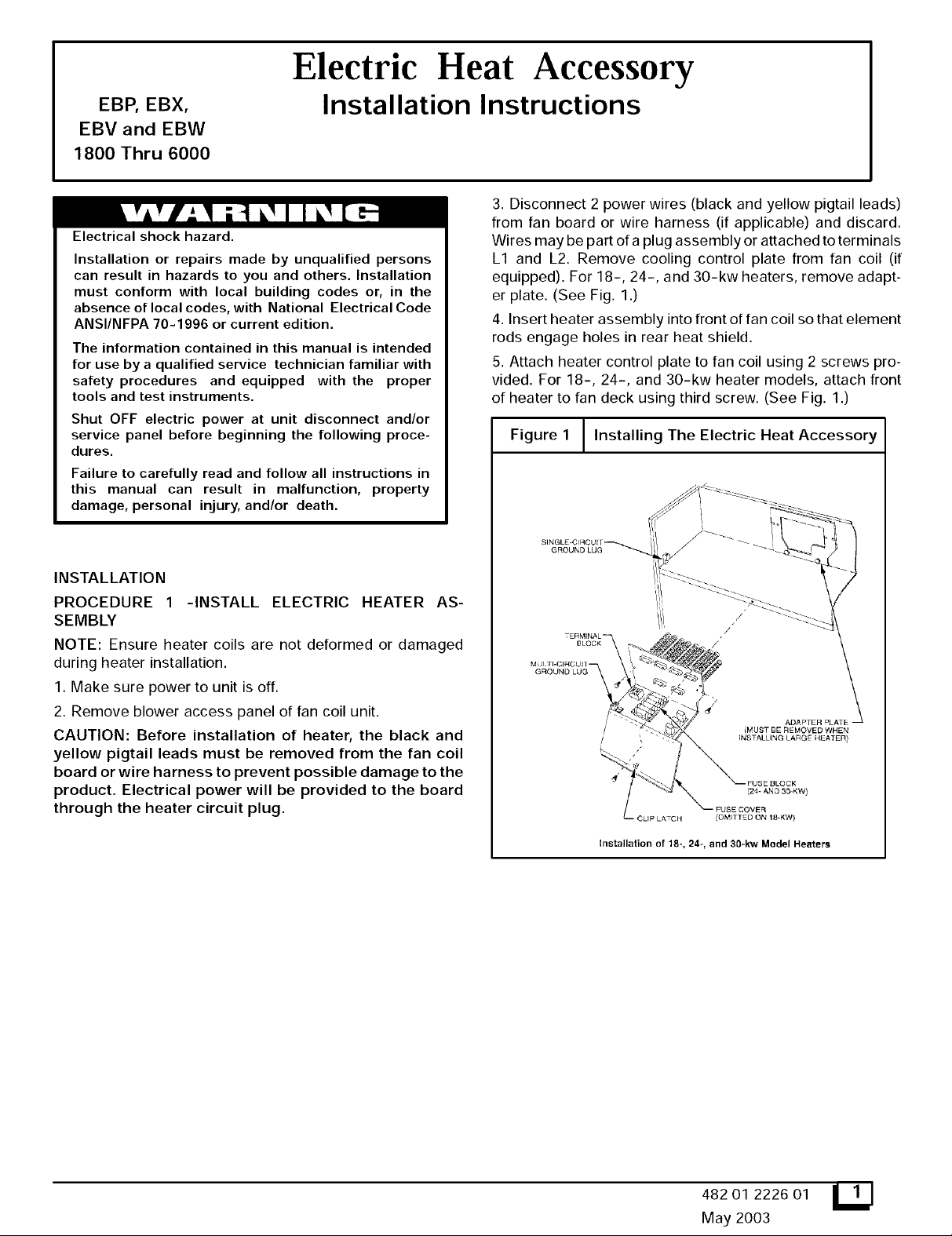
3. Disconnect 2 power wires (black and yellow pigtail leads)
from fan board or wire harness (if applicable) and discard.
Wires may be part of a plug assembly or attached to terminals
L1 and L2. Remove cooling control plate from fan coil (if
equipped). For 18-, 24-, and 30-kw heaters, remove adapt-
er plate. (See Fig. 1.)
4. Insert heater assembly into front of fan coil so that element
rods engage holes in rear heat shield.
5. Attach heater control plate to fan coil using 2 screws pro-
vided. For 18-, 24-, and 30-kw heater models, attach front
of heater to fan deck using third screw. (See Fig. 1.)
Figure 1 I Installing The Electric Heat
L
Accessory
INSTALLATION
PROCEDURE 1 -INSTALL ELECTRIC HEATER AS-
SEMBLY
NOTE: Ensure heater coils are not deformed or damaged
during heater installation.
1. Make sure power to unit is off.
2. Remove blower access panel of fan coil unit.
CAUTION: Before installation of heater, the black and
yellow pigtail leads must be removed from the fan coil
board or wire harness to prevent possible damage to the
product. Electrical power will be provided to the board
through the heater circuit plug.
GROUND LUG
/
/
ADAPTER PLA] E_
iMUST BE REMOVED WHEN
(24- AND 30-KW)
_E COVEq
- CUP LATCH
Installation of 18-, 24-, and 30-kw Model Heaters
(OMITTED ON 18-KW)
3E HEA_ER)
482 01 2226 01
May 2003
Page 2
Model Description Use With
EHKOSAKN 5 Kw Single Phase All
EHKO7AKN 8 Kw Single Phase All
EHKO7AKB 8 Kw Single Phase All
EHKO9AKCN 9 Kw / Single Phase (Field convertible to 3 phase) 2-5 Ton
EHKIOAKN 10 Kw Single Phase All
EHKIOAKB 10 Kw Single Phase All
EHK15AKF 15 Kw Single Phase 2-5 Ton
EHK15AKB 15 Kw Single Phase 2-5 Ton
EHK15AHN 15 Kw 3 Phase 3-5 Ton
EHK18AHN 18 Kw 3 Phase 3 1/2 - 5 Ton
EHK2OAKF 20 Kw Single Phase 2 1/2 - 5 Ton
EHK2OAKB 20 Kw Single Phase 2 1/2 - 5 Ton
EHK25AHCF 24 Kw / 3 Phase (Field convertible to single phase) 4 - 5 Ton
EHK3OAHCF 30 Kw / 3 Phase (Field convertible to single phase) 4 - 5 Ton
All AKB Models are Circuit Breaker Models
Fan HEATER KW
Coil
Sizes 5 8 9 10 15 18 20 24 30
1800 525 525 600* - - -
2400 700 700 700 700 775* - -
3000 875 875 875 875 1060" -
3600 1050 970 970 970 920 1040 -
4200 1225 1225 1225 1225 1225 1225 -
4800 1400 1400 1400 1400 1400 1400 1400 1400
6000 1750 1750 1750 1750 1750 1750 1750 1750
Indicates medium speed (blue). All other motor speeds at low tap.
PROCEDURE 2 -ATTACH FUSE BOX OR CIRCUIT
BREAKER BOX
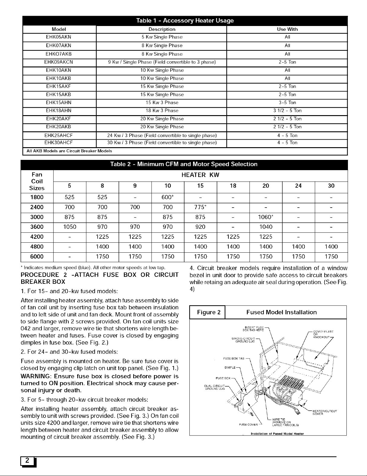
1. For 15- and 20-kw fused models:
After installing heater assembly, attach fuse assembly to side
of fan coil unit by inserting fuse box tab between insulation
and to left side of unit and fan deck. Mount front of assembly
to side flange with 2 screws provided. On fan coil units size
042 and larger, remove wire tie that shortens wire length be-
tween heater and fuses. Fuse cover is closed by engaging
dimples in fuse box. (See Fig. 2.)
2. For 24- and 30-kw fused models:
Fuse assembly is mounted on heater. Be sure fuse cover is
closed by engaging clip latch on unit top panel. (See Fig. 1.)
WARNING: Ensure fuse box is closed before power is
turned to ON position. Electrical shock may cause per-
sonal injury or death.
3. For 5- through 20-kw circuit breaker models:
After installing heater assembly, attach circuit breaker as-
sembly to unit with screws provided. (See Fig. 3.) On fan coil
units size 4200 and larger, remove wire tie that shortens wire
length between heater and circuit breaker assembly to allow
mounting of circuit breaker assembly. (See Fig. 3.)
4. Circuit breaker models require installation of a window
bezel in unit door to provide safe access to circuit breakers
while retaing an adequate air seal during operation. (See Fig.
4)
Figure 2 [ Fused Model Installation
DIMPLE 7
F
_ WIRE TIE
(REMOVE ON
LARGE FAN COILS)
Installation oi FIl_ed Model Heater
Page 3
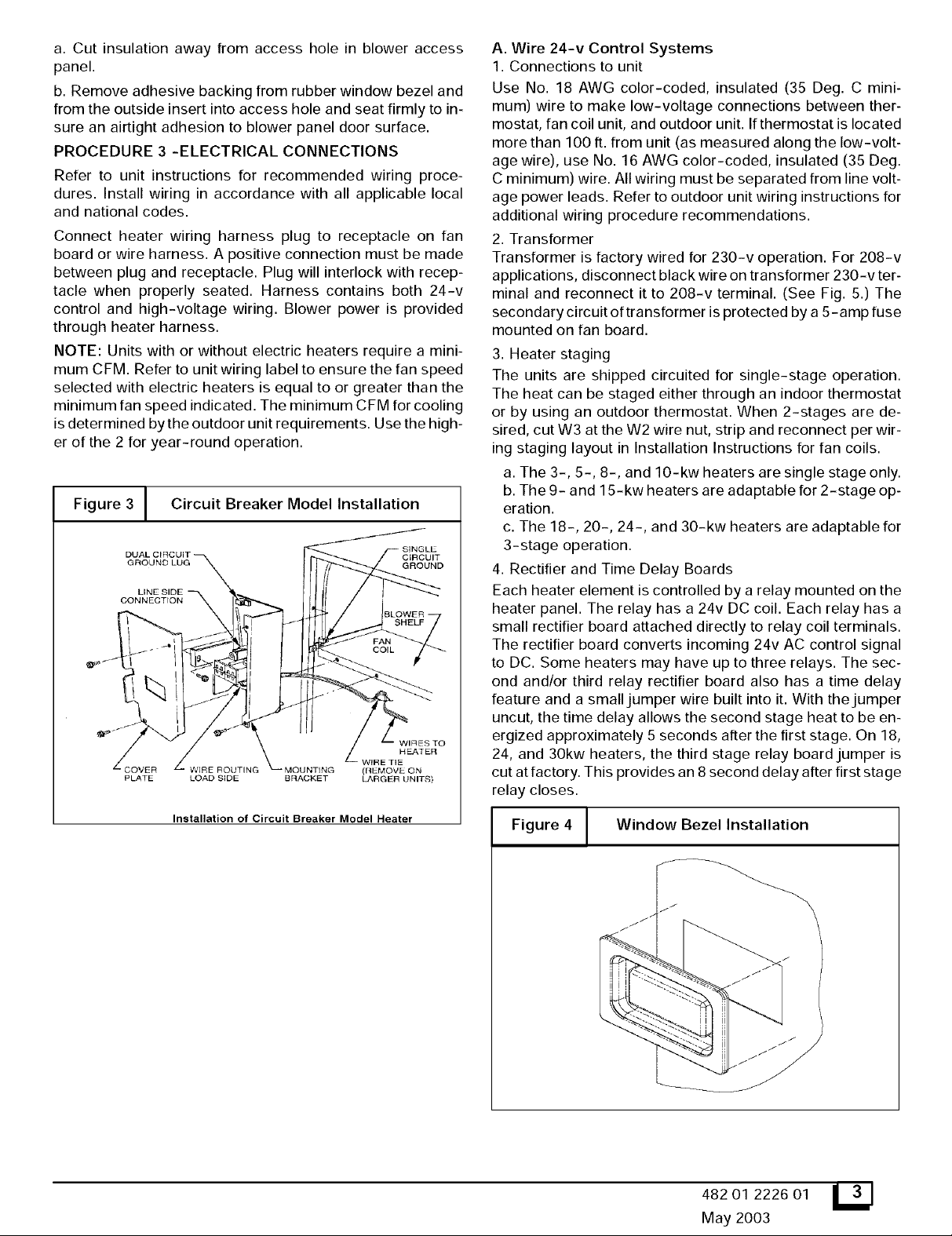
a. Cut insulation away from access hole in blower access
panel.
b. Remove adhesive backing from rubber window bezel and
from the outside insert into access hole and seat firmly to in-
sure an airtight adhesion to blower panel door surface.
PROCEDURE 3 -ELECTRICAL CONNECTIONS
Refer to unit instructions for recommended wiring proce-
dures. Install wiring in accordance with all applicable local
and national codes.
Connect heater wiring harness plug to receptacle on fan
board or wire harness. A positive connection must be made
between plug and receptacle. Plug will interlock with recep-
tacle when properly seated. Harness contains both 24-v
control and high-voltage wiring. Blower power is provided
through heater harness.
NOTE: Units with or without electric heaters require a mini-
mum CFM. Refer to unit wiring label to ensure the fan speed
selected with electric heaters is equal to or greater than the
minimum fan speed indicated. The minimum CFM for cooling
is determined bythe outdoor unit requirements. Use the high-
er of the 2 for year-round operation.
Figure 3 J Circuit Breaker Model Installation
I I '_ J SHELF
Installation of Circuit Breaker Model Heater
I BLOWER
A. Wire 24-v Control Systems
1. Connections to unit
Use No. 18 AWG color-coded, insulated (35 Deg. C mini-
mum) wire to make low-voltage connections between ther-
mostat, fan coil unit, and outdoor unit. Ifthermostat is located
more than 100 ft. from unit (as measured along the low-volt-
age wire), use No. 16 AWG color-coded, insulated (35 Deg.
C minimum) wire. All wiring must be separated from line volt-
age power leads. Refer to outdoor unit wiring instructions for
additional wiring procedure recommendations.
2. Transformer
Transformer is factory wired for 230-v operation. For 208-v
applications, disconnect black wire on transformer 230-v ter-
minal and reconnect it to 208-v terminal. (See Fig. 5.) The
secondary circuit oftransformer is protected by a 5-amp fuse
mounted on fan board.
3. Heater staging
The units are shipped circuited for single-stage operation.
The heat can be staged either through an indoor thermostat
or by using an outdoor thermostat. When 2-stages are de-
sired, cut W3 at the W2 wire nut, strip and reconnect perwir-
ing staging layout in Installation Instructions for fan coils.
a. The 3-, 5-, 8-, and 10-kw heaters are single stage only.
b. The 9- and 15-kw heaters are adaptable for 2-stage op-
eration.
c. The 18-, 20-, 24-, and 30-kw heaters are adaptable for
3-stage operation.
4. Rectifier and Time Delay Boards
Each heater element is controlled by a relay mounted on the
heater panel. The relay has a 24v DC coil. Each relay has a
small rectifier board attached directly to relay coil terminals.
The rectifier board converts incoming 24v AC control signal
to DC. Some heaters may have up to three relays. The sec-
ond and/or third relay rectifier board also has a time delay
feature and a small jumper wire built into it. With the jumper
uncut, the time delay allows the second stage heat to be en-
ergized approximately 5 seconds after the first stage. On 18,
24, and 30kw heaters, the third stage relay board jumper is
cut at factory. This provides an 8 second delay after first stage
relay closes.
Figure 4 / Window Bezel Installation
i
482 01 2226 01 L_J
May 2003
Page 4

B.PowerConnections
NOTE:Heatersupplycircuitwire sizeandovercurrent
protectionmustcomplywithNationalElectricalCode(NEC)
andULbranchcircuitrequirements.(SeeTable3)Wiresand
overcurrentprotection,integraltotheheater,arenotrequired
tomeetbranchcircuitrequirements.Internalcircuitprotec-
tionof60amps(maximum)isacceptable.
1.Unprotectedheaters:(SeeFigs.6,10,and11.)
a.The5-through10-kwsingle-phaseand15-and18-kw
3-phaseheaterscanbewiredfor single-supplycircuit
only.Supplycircuitconnectstoheaterpigtailleads(termi-
nalblockon18-kwheaters).
b.The3- throughlO-kwsingle-phaseheaterscanusea
separatefield-installed,factory-authorizeddisconnectkit
whichinstallsinfancoil.
NOTE:Refertowiringlabelforcomponentlocations.
c.The9-kwheaterisfactorywiredforsinglesupplycircuit,
singlephase.Toconvertheatertosinglesupplycircuit,3
phase:
(1.)Disconnectbluewirefromlimitswitch(LS3).Cut,
strip,andconnecttofieldwireL3.
(2.)Disconnectyellow wire from LS1 and connect to LS3.
(3.) Disconnect blue wire from relay 2terminal 2 and con-
nect to LSI.
2. Circuit breaker heaters: (See Figs. 7 and 9.)
a. The 3- through lO-kw heaters can be wired for single-
supply circuit only.
b. The 15- and 20-kw heaters can be wired for dual-supply
circuits only.
3. Fused heaters: (See Figs. 8, 12, 13, and 14.)
a. The 15- and 20-kw heaters can be wired for single- or
dual-supply circuits. Single-supply circuit wiring requires a
factory-authorized, single-point adapter kit.
b. The 24- and 30-kw heaters can be wired for single- or
multiple-supply circuits. Heaters are factory wired for single
circuit 3 phase. To convert heaters to single circuit single
phase, disconnect yellow lead from L3 and connect to LI.
Disconnect black lead from L3 and connect to L2. To convert
heaters to multiple-supply circuit single phase, remove and
discard leads between single-circuit terminal block and fuse
block. Remove and discard single-circuit terminal block. At-
tach L1through L6 power leads as indicated on label next to
fuse block.
C. Ground Connections
WARNING: According to NEC, ANSI/NFPA 70, and local
codes, cabinet must have an uninterrupted or unbroken
ground to minimize personal injury if an electrical fault
should occur. The ground may consist of electrical wire
or metal conduit when installed in accordance with ex-
isting electrical codes. (See Ground/Conduit Note be-
low.) Failure to follow this warning could result in an
electric shock, fire, or death.
NOTE: Use UL-listed conduit and conduit connector for con-
necting supply wire(s) to unit to obtain proper grounding. If
conduit connection uses reducing washers, a separate
ground wire must be used. Grounding may also be accom-
plished by using grounding lugs provided in control box.
1. For unprotected or single-circuit heaters, 1 equipment
ground connection is provided on fan coil unit. (See Fig. 1
or 2.)
2. For 15- and 20-kw circuit breaker heaters, an additional
ground lug is provided on circuit breaker mounting bracket
for dual-circuit grounding. (See Fig. 3.)
3. For 15- and 20-kw fused heaters, an additional ground
lug is provided on fuse mounting bracket for dual-circuit
grounding. (See Fig. 2.)
4. For 24- and 30-kw fused heaters, 2 additional ground
lugs are provided for single-phase, multi-circuit wiring.
(See Fig. 1.)
D. Fan Speeds
1.Speed tap selection is done atfan relay. To change motor
speeds, disconnect fan lead on relay and replace with mo-
tor speed tap desired. Save insulating cap and place on
motor lead that was removed from relay. (See Fig. 15.) Re-
fer to table below for further clarification of speed tap selec-
tions.
Common Yellow
High Black
Medium Blue (Factory Selected)
Low
PROCEDURE 4 -CONVERSION OF CIRCUIT BREAKER
FOR DOWNFLOW APPLICATIONS
1. Tag and disconnect factory wiring from terminals on circuit
breaker(s).
2. Pullwhite plastic release tab on the bottom of circuit break-
er straight out to release circuit breaker from bracket. (See
Fig. 16.)
3. Remove quick connect adapters from factory side of
breaker(s). Reinstall adapters on other end of breakers(s).
Be sure adapter is located between lug screw and plate.
Torque lug screw to 30-in-.lb.
4. Rotate breaker 180 degrees from its original position and
reinstall inbracket. Slide breaker slot into sheet metal tab and
snap breaker into place. Make sure both tabs engage break-
er. Reconnect wiring on opposite end. Make sure wires are
positioned as before.
5. Remount circuit breaker bracket into unit so that the switch
will be in UP position when ON.
PROCEDURE 5 -ATTACH WIRING DIAGRAM AND RAT-
ING LABEL
Attach heater rating label included with kit over existing elec-
trical information label located on front access panel of fan
coil. (See Fig. 17.) Ifkit contains multiple rating labels, ensure
correct label is applied (check phase and supply circuits).
PROCEDURE 6 -VERIFY INSTALLATION
After completion of heater installation, check wiring to ensure
tightness and that proper connections and routings have
been made. Ensure all electrical covers are in place and
proper labels have been applied. Reinstall blower access
panel before turning unit power on.
(Blue on 2 speed models)
Red
Page 5

Heater Amps
Heater Model
EHK05AKN11
EHK05AKN12
EHK07AKN1
EHK07AKB2
EHK09AKCN1
EHK09AKCNI[
EHK10AKN1
EHK10AKB2
EHK15AKF1
EHK15AKB2
EHK15AHN1
EHK20AHN1
EHK20AKF1
EHK20AKB2
EHK25AHCF1]
EHK30AHCF1]
230v
Kw
208v
5
5
8
8
9
9
10
10
15
15
15
18
20
20
24
24
30
30
3.8
3.8
6.0
6.0
6.8
6.8
7.5
7.5
11.3
11.3
11.3
13.5
15.0
15.0
18.0
18.0
22.5
22.5
Phase
1
1
1
1
1
3
1
1
1
1
3
3
1
1
3
1
3
1
Internal
Circuit Protection
None
None
None
Ckt Bkr
None
None
None
Ckt Bkr
Fuse
Ckt Bkr
None
None
Fuse
Ckt Bkr
Fuse
Fuse
Fuse
Fuse
Single Circuit
18.1 / 20.0
18.1 / 20.0
28.9 / 32.0
28.9 / 32.0
32.8 / 36.0
18.8/20.8
36.2 / 40.0
36.2 / 40.0
54.2 / 59.9
31.3 / 34.6
37.6/41.5
72.3 / 79.9
50.1 / 55.4
86.7 / 95.5
62.6 / 69.2
109/120
808f230v
Dual Circuit
L1,L2
36.2/40.0
36.2/40.0
36.2/40,0
36.2/40.0
mnn_N_
Branch Circuit
Min. Ampacity
cuit
208 t 230v "+
Dual Circuit Single Dual Circuit Single Dual Circuit Single Dual Circuit Single Dual Circuit
L1,L2 L3,L4 Circuit L1,L2 L3,L4 Circuit L1,L2 L3,L4 Circuit L1,L2 L3,L4 Circuit L1,L2 L3,L4
Heater Model
Single Cir-
EHK05AKN11 26.0 / 28.4 10 ] 10 10 ] 10 30 / 30 66 / 66
EHK05AKN12 31.2 / 33.5 8/ 8 10 / 10 35 / 35 85 / 88
EHK05AKB21 26.0 / 28.4 10 / 10 10 / 10 30 / 30 66 / 66
EHK05AKB22 3112 / 33.5 8/ 8 10 / 10 35 / 35 85 / 88
EHK07AKN1 44.7 / 48.5 8/ 8 10 / 10 45 / 50 59 / 60
EHK07AKB2 44.7 / 48.5 8/ 8 10 / 10 45 / 50 59 / 60
EHK09AKCN1 49.5 / 53.5 8/ 6 10 / 10 50 / 60 54 / 87
EHK09AKCN1 [ 32.0 / 34.5 8/ 8 10 / 10 35 / 35 83 / 85
EHK10AKN1 53.8 / 58.5 6/ 6 10 / 10 60 / 60 78 / 80
EHK10AKB2 53.8 / 58.5 6/ 6 10 / 10 60 / 60 78 / 80
EHK15AKF1 76.3/83.4 53.8/58.5 22.7/25.0 4/4 6/6 10/10 8/8 10/10 10/10 80/90 60/60 25/25 88/89 78/80 75/76
EHK15AKB2 53.8/58.5 22.7/25.0 6/6 10/10 10/10 10/10 60/60 25/25 78/80 75/76
EHK15AHN1 47.7 / 51.8 8/ 6 10 / 10 50 / 60 56 / 90
EHK18AHN 1 55.5 / 60.4 6/ 6 10 / 8 60 / 70 76 / 77
EHK20AKF1 98.9/108.4 53.8/58.5 45.3/50.0 3/2 6/6 8/8 8/6 10/10 10/10 100/110 60/60 50/50 85/109 78/80 59/59
EHK20AKB2 53.8/58.5 45.3/50.0 6/6 8/8 10/10 10/10 60/60 50/50 78/80 59/59
EHK25AHCF1]
EHK30AHCF1] 144.8/158.5 0/ 00 6 / 6 150 / 175 117 / 150
71.2/77.8 4/4 8/8 80/80 94/95
116.9/127.9 1/1 6/6 125/150 115/116
86.8/95.0 3/3 8/8 90/100 97/98
Min. Wire Size (AWG) Min. Grnd. Wire Size Max Wire Length
208 t 230v I I 208 t 230v Max FusefCkt Bkr Amps 208 t 230v(ft.) [[
L3,L4
18.1/20.0
18.1/20.0
36.2/40.0
36.2/40.0
I
] Field convertible to 1 phase, single or multiple supply circuit,
[ Field convertible to 3 phase.
* Includes blower motor arnps o1 largest fan coil used with heater.
I I Copper wire must be used. If other than uncoated (non- plated), 75 Degrees C ambient, cop-
per wire (solid wire for 10 AWG and smaller, stranded wire for larger than 10 AWG) is used, consult
applicable tables of the National Electric Code (ANSI/NFPA 70).
[ [ Length shown is as measured 1 way along wire path between unit and service panel for a volt-
age drop not to exceed 2%.
NOTES:
1, For fan coil sizes 1800- 3600.
2. For fan coil sizes 4200- 6000.
482 01 2226 01 151
May 2003
Page 6

Figure5 J Connection of Transformer
SECOI',
RED
Figure
7 _ 5, 8 and 10 Kw Circuit Breaker
and Disconnect Heaters
I
Power I 1111 I
Wiring _ L2_ --
YEL
BLK
Figure 6 ] 5, 8, 9, and 10 Kw Non-fused Heaters
L1
Field Yellow
Power ,_
Wiring L2 Black
Field (_
Ground Ground
Wiring Lug
(9kw is field convertible to 3-phase.
See Procedure 3. B. 1. c.)
A00076
Field
Ground Ground
Wiring Lug
Figure 8 [ 15 and 20 Kw Fused Heaters
L4 .... ,__ Circuit 1 :L1-L2
L£ L3
Field Ground @ Ground lug
Wiring
Field Ground @ Ground lug
Wiring
(15 and 20kw fused heaters are factory wired for dual
supply circuits. Single supply circuit is possible
with approved single point wiring kit.)
Circuit 2 : L3-L4
A00078
Page 7

Figure 9 ] 15 and 20 Kw Circuit Breakers
Figure 11[ 18 Kw 3-Phase Heater
r
J _llll_ I Circuit 2 : L3-L4
mL2
o_
t_._
_ L3- -
L4
Fie]dGround --
Wiring
Field Ground ........ _ Ground lug
Wiring
Figure 10] 15 Kw 3-Phase Heater
L1
Field L2 z_
Power
Wiring
I Circuit 1 : L1-L2
(_) Ground lug
L3 _
Field
Ground
Wiring
Yellow
Black
Blue
_) Ground Ilug
A00080
bq
oq
oq
Figure 12[ 24 and 30 Kw Heaters
Field L1-- -- _::=::_ F
Power L2---
Wiring
L3----
Field Ground
Wiring
©
©
©
(_) Ground lug
A00081
_EF------_
-DD
oD B
_D U
-DD D
(_) Ground lug
A00082
482 01 2226 01
May 2003
Page 8

Figure13] 24and30KwHeaters
Figure 16[ Conversion of Circuit Breaker
Field
Llmm
-DE____D
Power L2---
Wiring
-DD D
Field Ground
Wiring
(Single Phase, Single Supply Circuit-Field Modified)
Figure 14] 24 and 30 Kw Heaters
L5
-- -IZ
Field
Power L1
Wiring L6 ---
L3
-- -IZ_
L4 m
L2 _
(_ Ground lug
Circuit 1 :L1-L2
Circuit 2:1_3-L4
Circuit 3:L5-L6
A00083
RELEASE TAB
@
OFF
[]
Q
Field Ground- (_ Ground lug
Wiring
Field Ground (_ Ground lug
Wiring
Field Ground (_ Ground lug
Wiring
(Single Phase, Multiple Supply Circuits-Field Modified)
Figure 15.[ Motor Speed Tap and Fan Relay
A00084
Figure 17[ Heater Rating Label Location
FROM KIT
 Loading...