

Page 1
EAIC
High Efficiency
Electronic Air Cleaner
Series 1014B and 1020B
J
anstaalation • Operation o
Maintenance
"__
o
:: ::::: ::: ::: ::!:::: :;: : ::::: : ::: :':: :::;:
155587-0099-D4 616 01 1003 O0
Page 2
Table of Contents
Introduction ....................................................................................... I
Unit Components .......................................................................................2
Operation ...................................................................................................3
!) Regular Dusting & "White Dust"° ...........................................3
2) Ozone .................................................................................... 3
3) High Altitude Operation .................................................... 4
Maintenance of Your Electronic Air Cleaner ................................... 5
1) Washing the Cells and Pro-filter(s) .................................... 5
2) Replacing the Ionizer Wires ...................................................6
3) Cleaning the Air Flow Sensor (AFS) .................................. 6
Common Questions & Answers ...................................................................7
Common Troubleshooting Techniques ............................................. 9
Unit Dimensions .................................................................................. 10
HVAC INSTALLATION INSTP,UCTIONS.................................................... 11
(for use by authorized HVAC contractors only)
Technical Specifications ....................................................................... 11
Installation Considerations ................................................................... 12
Application ............................................................................... 12
Installation Requirements ...................................................... 12
Air Conditioning .................................................................................12
Evaporative Hure!differs .......................................................... 12
Atomizing Humidifiers ...............................................................13
Sheet Metal Installation .......................................................... 13
Transitions ............................................................................... 13
Outdoor Air ............................................................................ 13
Turning Vanes ........................................................................ 13
Location Selection ............................................................................ 14
Typical Mounting Positions .............................................................. 15
Mechanical Installation ....................................................................... 16
Electrical Installation ......................................................................... 18
System Checkout .............................................................................. 19
Troubleshooting .................................................................................... 20
Air Flow Sensor ....................................................................... 20
Primary Circuit .............................................................................21
Secondary Circuit - Ionizing-Collecting Cel! ..........................22
Secondary Circuit- Power Supply ........................................ 23
Unit Diagram & Parts List ........................................................................ 25
Warranty ................................................................................................ 26
Page 3
INTRODUCTION
This Electronic Air Cleaner is a two-stage electrostatic precipitator. The air cleaner is designed to
remove airborne particulates, including dust, dirt, smoke, pollen, virus, spores, bacteria, and
mold from indoor air.
Air movement through the unit isprovided by the heating, air conditioning or ventilating system
blower. As dirty air enters the air cleaner, the air passes through Metal Mesh Pre-filters_ The Pre-
filters prevent lint, pet hair and other large particulates from entering the air cleaner, it is
important that these filters be in place to prevent excessive dirt loading of the air cleaner
Ionizing-Collecting Cells° These filters extend the time interval between scheduled maintenance
of the air cleaner, which allows the Ionizing-Collecting Cells to provide clean air for a longer
period between washings_
The pre-filtered air then passes through a two-stage Electronic Air Cleaner. In the first stage, alf
airborne particulate, even submicron size, are electronically charged (positive) as they pass
through the ionizer sectiom The ionizer field is a result of a corona discharge emanating from
the fine, tightly strung wires suspended between two adjacent flat piates, in the second stage,
the charged particulate passes through an intense electrical field established between
alternately charged and grounded parallel collector plates. Here, the charged (positive)
particulate is attracted to the ground (negative) plates and removed from the air stream.
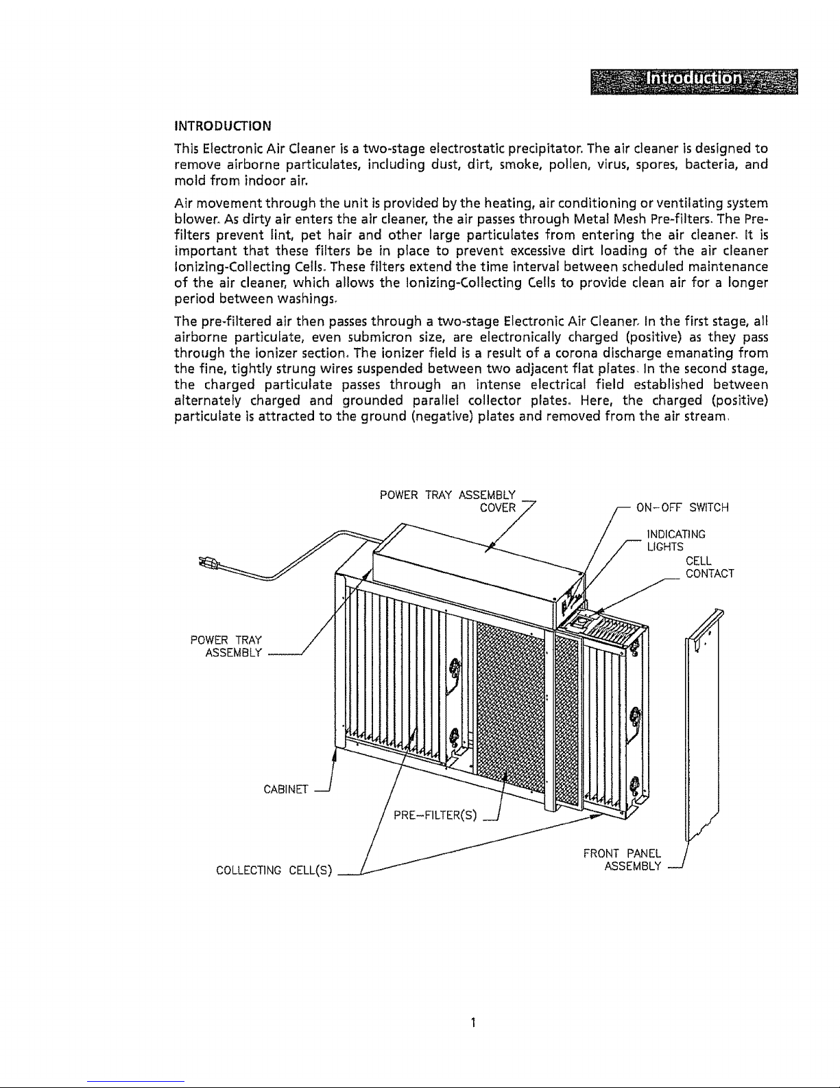
POWER TRAY ASSEMBLY
COVER
ON-OFF SWITCH
INDICATING
LIGHTS
CELL
CONTACT
POWER TRAY
ASSEMBLY
CABINET
COLLECTING CELL(S)
FRONT PANEL
ASSEMBLY
I
Page 4
Cabinet
Mounts to existing ductwork; houses the Ionizing-Collecting Cells and Pre-fitters.
Ionizing-Collecting Cells
Collect the dust, dirt and other particulates in the air. They contain the ionizing and collecting
sections_ The cells must be installed with the ionizing wires on the air intake side. A spring
contact is located on the top of each cell and must be in the position to make contact with the
contact board assemblies on the bottom of the Power Tray Assembly.
Pre-filters
Trap large particulates before they enter the Ionizing-Collecting Cell
Power Tray Assembly
Contains the indicating lights, solid-state power supply, contact boards and electrical controls
including the ON/OFF switch and safety interlock switch. A power cord at the rear of the 120 volt
Power Tray allows the unit to be connected to a standard 120 volt outlet° A wiring compartment
isprovided on all models at the rear of the Power Tray allowing the option to permanently wire
the unit directly to the HVAC System Control°
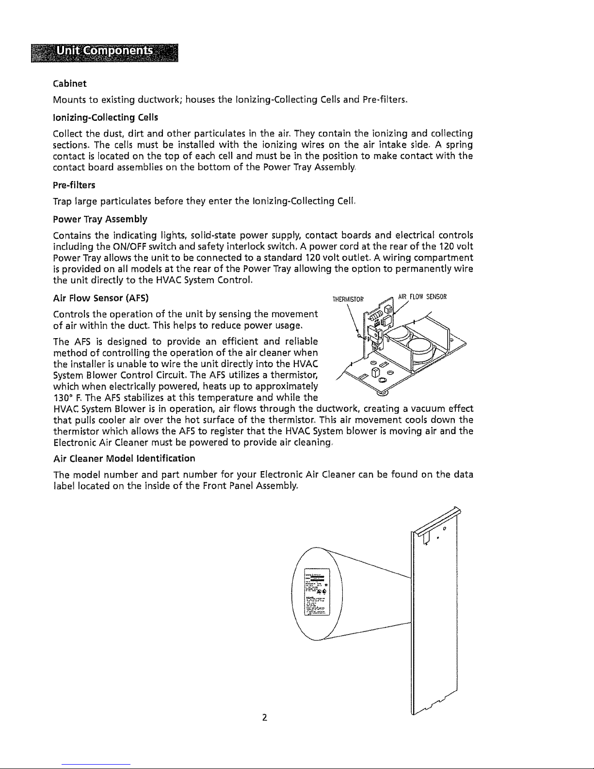
Air Flow Sensor (AFS)
Controls the operation of the unit by sensing the movement
of air within the duct. This helps to reduce power usage,
THERMISTOff
\,
AIR FLOWSENSOR
The AFS is designed to provide an efficient and reliable
method of controlling the operation of the air cleaner when
the installer is unable to wire the unit directly into the HVAC
System Blower Control Circuit. The AFS utilizes a thermistor,
which when electrically powered, heats up to approximately
130° RThe AFS stabilizes at this temperature and while the
HVAC System Blower is in operation, air flows through the ductwork, creating a vacuum effect
that pulls cooler air over the hot surface of the thermistor. This air movement cools down the
thermistor which allows the AFS to register that the HVAC System blower is moving air and the
Electronic Air Cleaner must be powered to provide air cleaning
Air Cleaner Model Identification
The model number and part number for your Electronic Air Cleaner can be found on the data
label located on the inside of the Front Panel Assembly°
J
Page 5
Regular Dusting and "White Dust"
Your new Electronic Air Cleaner will efficiently clean and filter your household air° It will not
eliminate the need for regular dusting of your furniture and belongings_ Duct-mounted air
cleaners can only clean air that reaches the air cleaner. Therefore, if the particulates are not
being carried to the air cleaner in the air stream, the air cleaner cannot remove them from
your home,
Occasionally a "white dust" may be noticed in bedrooms or newly furnished rooms. This is
mainly composed of lint which, because it is heavier than other particulates, settles before it
reaches your unit. This "white dust" is not mixed with airborne dirt particles, therefore, it is
clean and has no staining or soiling properties. Running the furnace blower continuously, day
and night, will help reduce this from occurring_
Ozone
Under normal operating conditions, all Electronic Air Cleaners produce minute quantities of
ozone as an incidental by-product. In fact, all electronic products, such as televisions, cordless
telephones and refrigerators, produce some amount of ozone° The average homeowner can
detect the smell of ozone concentrations as low as 25 to 100 ppb (parts per billion)° The
design of this unit has been tested and ozone production is approximately half of the
published permissible limits established by the Environmental Protection Agency. These limits
recommend that the concentration of indoor ozone not exceed 50 ppb_ Ozone is not harmful
in these concentrations. In fact, the ozone level in major cities can sometimes reach as high
as 100 ppb on a summer day_The addition of optional charcoal after-filters can help reduce
the smell of ozone generated by the air cleaner.
Normally, a new unit will produce more ozone than one that has been in operation for several
weeks_ This is due to sharp corners or manufacturing burrs on the ]onizing_Collecting Cell
Plates and is normal, As the Electronic Air Cleaner arcs and zaps, the voltage is vaporizing
these areas and tends to round them off_ This is part of the breaking-in period and the issue
is self-correcting, Also, high-altitude locations can be more susceptible to noticing the
presence of ozone,
An ionizing-Collecting Cell that has been damaged or bent (the designed spacing between
electrically<harged and ground components has been decreased) may also produce an
abnormal amount of ozone.
Page 6
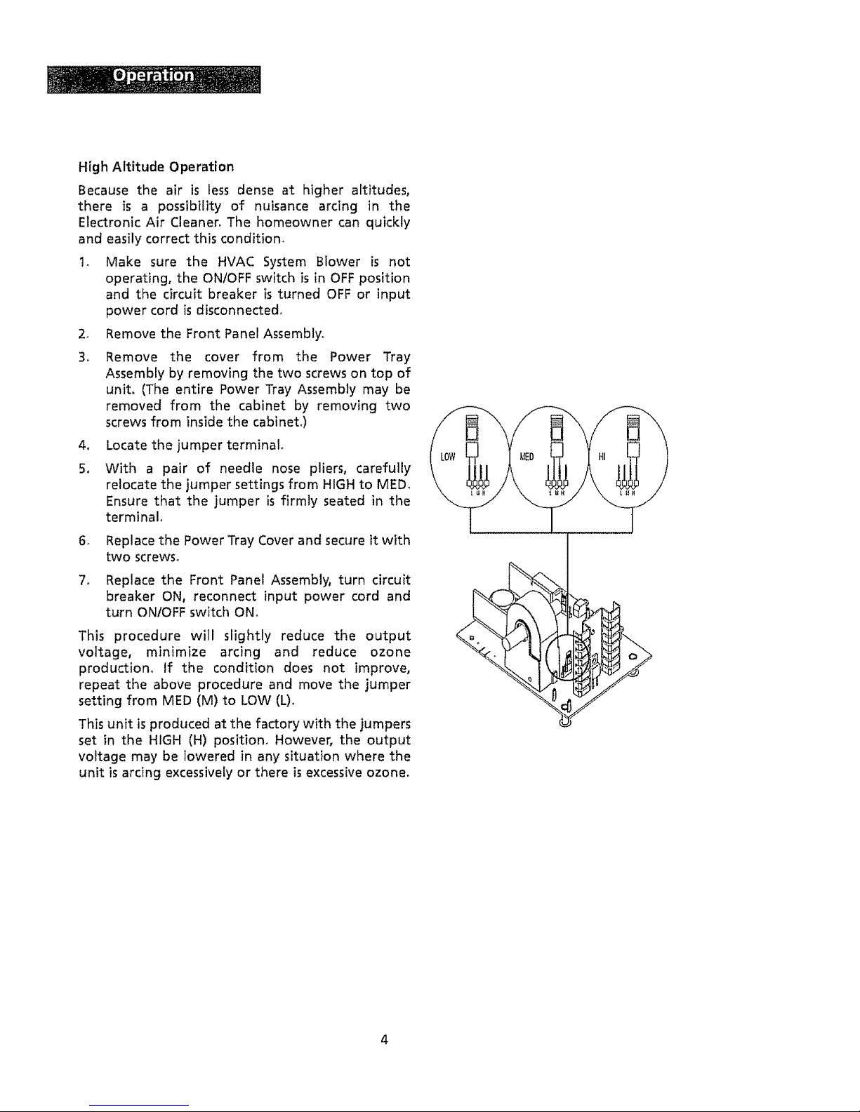
HighAltitudeOperation
Becausethe air is less dense at higher altitudes,
there is a possibility of nuisance arcing in the
Electronic Air Cleaner, The homeowner can quickly
and easily correct this conditiom
1_ Make sure the HVAC System Blower is not
operating, the ONIOFF switch is in OFF position
and the circuit breaker is turned OFF or input
power cord isdisconnected°
2_ Remove the Front Panel Assembly,
3_ Remove the cover from the Power Tray
Assembly by removing the two screws on top of
unit. (The entire Power Tray Assembly may be
removed from the cabinet by removing two
screws from inside the cabinet_)
4_
5.
Locate the jumper terminal°
With a pair of needle nose pliers, carefully
relocate the jumper settings from HIGH to MED.
Ensure that the jumper is firmly seated in the
terminal°
6, Replace the Power Tray Cover and secure it with
two screws°
7o Replace the Front Panel Assembly, turn circuit
breaker ON, reconnect input power cord and
turn ONtOFF switch ON,
This procedure will slightly reduce the output
voltage, minimize arcing and reduce ozone
production° If the condition does not improve,
repeat the above procedure and move the jumper
setting from MED (M) to LOW (L).
This unit is produced at the factory with the jumpers
set in the HIGH (H) position. However, the output
voltage may be lowered in any situation where the
unit is arcing excessively or there is excessive ozone,
%
4
Page 7
WASHINGIONIZING-COLLECTING CELLSAND PRE-FILTERS
Regu{ar washing of the Ionizing+Collecting Cells is necessary to ensure proper performance,
A thorough washing once every two months will be adequate for most installations, More
frequent washing (once a month) may be necessary with some installations (new home for
example) where there is new carpeting, plaster dust or excessive cigarette smoke.
To Remove the ionizing-Collecting Cells and Pre+filters from the Air Cleaner:
1, Turn air cleaner ON/OFF switch to OFF position_ Wait 15 seconds+Remove Front Panel Assembly+
2. Carefully remove the fonizing+Coliecting CeiL(s)and Pre-filter(s) and set aside in a safe place_
3+Do not drop the Ionizing-Collecting Ce!loThis can cause damage to the cell plates or ionizing
wires which results in excessive arcing and poor performance.
To Wash Ionizing-Collecting Cells and Pre-filters:
We suggest you follow the instructions below to properly and thoroughly clean your
Ionizing-Collecting Cells.
1, Place enough hot water in a utility tub to cover the first cell+ Dissolve 2+4 oz, of granulated
automatic dishwasher detergent (NOT laundry detergent) in the water=,
2_ Allow the cell to soak for 30 minutes, Agitate it up and down in the solution until it appears
clean and remove_
3_
4+
5,
+
Repeat with second cell (if applicable),
Agitate the Pre-filters up and down in the solution until they appear clean.
With a hose, rinse the ionizing-Collecting Cells and Pre-filters, The hose should be held
about 10" from the cell plates and at a slight angle for maximum cleaning results, Be careful
not to spray the ionizing wires directly with the hose as the water pressure can cause the
wire(s) to stretch and break, The cell frame should be thoroughly rinsed along the edges to
dislodge any trapped lint or dirt+ Carefully wipe a damp cloth or sandpaper (not emery cloth)
along the ionizing wires,
Stand Ionizing-Collecting Cells and Pre-filters in upright position and allow to dry two hours_
You may experience a slight discoloration of the a[uminum collector cell plates after
washing_ This is a normal chemical reaction between the aluminum and detergent and will
not harm your unit or affect its performance+
To Replace Cells in the Air Cleaner;
1+ Replace Pre+filter and Ionizing-Collecting Cells in cabinet. Check that airflow arrow on Cells
point in same direction as air flows through the duct° (If you have to force the ceil past the
positioning screw in the cabinet bottom, the cell is probably in the incorrect position.)
2+ Replace Front Panel Assembly (engage tabs on lower edge of door into slots in cabinet),
Carefully close the Panel
3+ Turn air cleaner ON/OFF switch to ON position_
Page 8
REPLACING THE IONIZING WIRES
Instances of the Ionizing Wires breaking are minimal due to the constant tension design and
fixed location of the lonizing Wire supports. When an Ionizing Wire breaks, the efficiency of the
Electronic Air Cleaner will decrease slightty_ However, the unit will continue to operate with a
broken Ionizing Wire as long as the broken wire has not caused a short in the secondary circuit
of the unit_ Remove all loose and broken wires as soon as they are identified.
We recommend contacting a qualified HVAC contractor for replacement parts and/or servicing.
ionizing Wires are supplied in a coiled spring configuration, with a clinch nut on each end of the
wire. Replacement requires a pair of needle nose pliers° Exercise caution in removing any broken
wires in the Ionizing-Collecting Cell. The removal of broken wires will prevent accidental
shorting of the cell and reduce the need for further maintenance.
Use the following procedure when replacing an Ionizing Wire:
1o Turn Air Cleaner ON/OFF switch to OFF position,, Wait 15 seconds° Remove the Front Panel
Assembly and remove the Ionizing-Collecting Cells from the unit.
2. Carefully remove all remains of the broken wire from the cello
3_ Grip the new wire at each end with your thumb and index finger, While stretching the wire
to approximately 6", allow one end of the wire to uncoil between your thumb and index
finger_
4. Place one end of the wire in the slot of the stainless steel wire support located on the
Ionizing-Collecting Cell asviewed from the front of the cell. This support ispartially covered
by the cel! brace in front of the support°
5, Grip the other end of the tonizing Wire with needle nose pliers and insert the terminated
end of the wire into the slot in the wire support on the opposite end of the lonizing-
Collecting Cell,
6. The wire should have sufficient tension to be self supporting and remain suspended
between the slots in the wire supports.
CLEANING THE AIR FLOW SENSOR
If the air cleaner is installed in a location that is dusty and dirty, the sensor (thermistor) on the
AFS can become coated with dirt and lint. This coating can insulate the AF5 and keep it from
operating properly, To clean the thermistor, turn the unit OFF, dip a cotton swab in rubbing
alcohol and carefully insert into the 3/16" diameter hole located on the front right hand side of
the Power Tray Assembly (when facing the unit). Carefully twirl the cotton swab between your
fingers, making sure the tip is lightly in contact with the gray disc (thermistor), cleaning the
insulating coating from the thermistor,
6
Page 9
COMMON QUESTIONS AND ANSWERS
Q_
Am
a_
A,
a_
A_
Q.
Ao
Q,
Ao
a_
A_
Why isn't my Electronic Air Cleaner cleaning my air?
The air cleaner is most likely working just like it was designed, However, many
factors can affect the performance of the unit_ Are air return registers located in
the ceiling? If so, it will be difficult for the air flow to carry heavier particulates to
the air cleaner. If the dirt does not get to the air cleaner, it cannot be removed
from the air. Are both the Red and Green indicating lights illuminated? If not, the
unit may be in need of servicing.
It still isn't cleaning my air the way 1want it to, What can 1do?
It is recommended that you operate the HVAC system continuously so that the air
movement will carry the dirt to the air cleaner where it can be collected.
Unfortunately, there will always be some dirt that isleft behind on the appliances,
furniture, etc. Regular dusting is recommended to stir up these pockets of dust so
that they can enter the air stream and be removed by the Electronic Air Cleaner.
When t turn on my Electronic Air Cleaner, the lights come on for a couple of
seconds and then turn off. The air cleaner isn't working!
The air cleaner is operating properly as long as both the Red and Green indicating
lights are illuminated. Try turning the HVAC blower ON and then turning the
Electronic Air Cleaner ON_This should solve the problem
What is the zapping noise I am hearing from my unit? Should I be concerned?
The zapping or popping noise that you are hearing isthe sound of larger particles
being "vaporized" by the Ionizing-Collecting Cel!oThis is normal and is no cause
for alarm_ As your HVAC system blower moves the air through the ductwork and
allows the Electronic Air Cleaner to clean the air, the noise will diminish, However,
there will always be instances when larger particles enter the Ionizing-Collecting
Cell, and are "vaporized",
Should 1hear this zapping noise all the time?
All Electronic Air Cleaners will occasionally zap or pop as larger particles pass
through the lonizing_Colfecting Ceils° However, if the sound is constant or is
repetitive in nature, then a large particle may have become lodged in the lonizing_
Collecting cell and may require removal by cleaning, If cleaning the Ionizing-
Collecting Cell does not stop the noise and/or there are no large particles trapped
in the ionizing-Collecting Cell, then the cause could be a broken/loose ionizing
wire, bent collector plate or other mechanical fault.
What if I no longer hear any popping or zapping noises coming from my unit? Is
it still cleaning the air?
tf the zapping noises stop and the air cleaner is not in need of servicing, then one
of two situations has occurred_ First, the Electronic Air Cleaner has successfully
removed all larger particles from the air and is cleaning microscopic particles
which do not cause the zapping noises° Second, the HVAC system blower is not
operating and air is not flowing through the ductwork_ The Electronic Air Cleaner
cannot remove particles if the air stream is not moving.
Page 10

Q_
Am
Q_
Ao
I lost power to my home during a storm, Should 1worry about the Electronic Air
Cleaner ?
The most common problem associated with power outages is the Electronic Air
Cleaner will not turn on properly after power is restored_ If the Green INPUT
POWER indicating light is illuminated, and the Red CELL ENERGIZED indicating
light is illuminated while the HVAC system blower is operating, the unit is
operating properly_, To reset the Electronic Air Cleaner, turn the HVAC system
blower OFF,turn air cleaner OFF,wait one minute, turn air cleaner ON, and then
turn HVAC system blower ON_If the Red and Green lights do NOT come on while
the HVAC system blower is in operation, after a storm, the power supply in the
Electronic Air Cleaner may be short circuited. Contact your local HVAC contractor
for further assistance.
My installer told me to keep my HVAC system blower running all the time, but I
don't want to increase my power bilto What should I do?
It is recommended that you keep your HVAC system blower operating all the time
to achieve the maximum air cleaning efficiency of the Electronic Air C]eanero This
will allow the Electronic Air Cleaner to do what it is designed to do, which is clean
the air_ Remember that if the air does not reach the air cleaner, it cannot be
cleaned. On average, your Electronic Air Cleaner will use the same amount of
electricity as a 55W light bulb_ The energy usage of the HVAC system blower will
depend on the age and size of your system, energy costs in your regional location
and other variables.
The best solution is to operate the HVAC system blower in a continuous mode for
a month or two, estimate annual energy costs, and base your final decision with
what you feel most comfortable.
Page 11

Common Troubleshooting Techniques
SYMPTOM
Rapid Arcing or
Zapping
Excessive Ozone
Smell
Radio or Television
interference
Hissing or Sizzling
Noise
Green LED Light is
not On
Red LED Light is
not On
POSSIBLECAUSES
Broken or loose ionizing wire (s)
CORRECTIVE ACTION
iir iii iir iiii ;ii1_ _ITii;i i _ lit ....................................
Remove broken or loose wire and replace
with new wire
Dirty Ionizing-Collecting Cell Clean the Ionizing-Collecting Cell
Damaged or bent collector plates Straighten plates with needfe nose pliers
or replace entire Ionizing-Collecting Celt
Dirty insulator caps on Ionizing-
Collecting Cell
Defective Air Flow Sensor
,Lpos e h!,g h,:vo !ta,g,e connections
=oor electrical ground
Poor electricalcontact in the secondary
electrical circuit
No power available
Loose wiring at ONIOFF switch
Defective ON/OFF switch
ONIOFF switch not in ON position
Clean with warm soapy water and rinse
well
Clean or replace Air Flow Sensor
Rewire Air Cleaner to the HVAC system
blower by qualified HVAC c0nt[a_0r _
Uncommon occurrence- check for good
common ground for air cleaner
Ensure that there is a good connection
between the top of the lonizing-CoIlecting
Cell and the bottom of the contact board
Contact HVAC contractor
Reset circuit breaker
Replace fuse
Check for secure connection
Replace ONtOFF switch
Loose wiring within power pack
assembly
Broken or shorted electrical Contact HVAC contractor
component
Excessive dirt build-up on ionizing Clean wires with alcohol and allow to dry
wires thoroughly before turning the unit ON
Contact board assemblies are corroded Replace contact board assembly
or carbonized
Broken ionizing wire Removebroken wire and replacewith new wire
Dirty Ionizing-Collecting Cell Clean the Ionizing-Collecting Cell
Foreign object located between
Removeobject from Ionizing-Collecting Cell
collector plates
Damaged or bent collector plates Straighten plates with needle nose pliers
or replace entire Ionizing-Collecting Cell
Insulators are corroded or carbonized Replace insulators or Ionizing-Collecting Cell
Turn the unit ON
Check for secure connections
Contact HVAC contractor
Page 12

O°
e
L ,¢,
[- ,_"[,5]
,
t
"D_ ............................
MODEL "A" 'B" "C" "D" "E" *F" "G"
IN, MM IN, MM IN, MM IN, MM IN. MM IN, MM IN, MM
t EAIC1020 24-_ 616 t7-_ 454- 20_ 531 22_ 572 24.._ 632 7-_ 181 2t--_ 545
t EAtC1014 20-4 514 13-_ 352 16-_ 429 224 572 24-_ 632 7-_t 181 2t-_ 545
10
Page 13

: :::Fo rlQuail fled HVAC ::':::::i::iii
: Installer Only
_ ::_:i WARNING: ELECTRICAL SHOCK HAZARD
Failure to follow this warning could result in
personal injury or:death.
The following section is to
contractor or
be used bya qualified HVAC
installer ONLY.
Theseprocedures are not to be attempted by any person not
qua!ified to work:with high voltage or familiar with the
installation oftliisltype of alrlcleaner. Seller cannot be held
responsible for ::any:injury or damage by any person not
qualified to install this product,
Technical Specifications
Model EAICI014
Size (16x25)
Part Number 120VI50-60Hz 455601-008
Part Number 240VI50-60Hz
EAICI020
(20x25)
455600-008
Maximum Rated Airflow t400 CFM (2380mlhr) 2000 CFM (3400mthr)
Maximum Pressure Drop ,,11inch w,,g, @1400 CFM o14 inch w,g. @2000 CFM
Cell Weight 10 lbs eao (4_,5kg) t2 Ibs ear (5,5 kg)
(2 Cells in ea. unit)
Unit Weight 32 Ibs_(14,6 kg) 36 Ibs, (164 kg)
Maximum Power 40 watts 48 watts
Consu mption
Electrical Output 2,5 MADC @ 6200 VDC 3,2 MADC @6200 VDC
Classification UL/CE UL/CE
Optional Accessories Charcoal After Filter Charcoal After Filter
11
Page 14

Application
Theaircleaner is used in forced air heating, cooling and ventilating
systems, tt should be installed in the system such that all the system air
is circulated through the air cleanerr The air cleaner will only remove
the airborne contaminants delivered to it; maximum performance is
obtained with the system blower set for continuous operation°
Installation Requirements
• The best location for the air cleaner is in the return air duct next to
the blower compartment. In this location, the blower motor and
cooling coils will be kept clean.
e DO NOT INSTALL THE AIR CLEANERIN THE DISCHARGE AIR DUCT
• Before installing the air cleaner, consider the application and type of
HVAC system present°
= Refer to the Typical Mounting Positions section for the most
common configurations°
= Refer to the Transitions section if a transition is required between
the duct work and the air cleaner.
. The unit must be readily accessible for periodic inspection and
cleaning of the Pro-filters and Ionizing-Collecting Cells to maintain
maximum efficiency and trouble free operation_
Air Conditioning
The air cleaner should be installed upstream of the cooling coil to
keep the coil clean and reduce air conditioning coil maintenance° A
clean coil will reduce utility costs by maintaining the coil's efficiency° if
the air cleaner is downstream of the cooling coil, condensation will
form on the cooled collector plates when the air conditioner cycles_
This will allow water droplets to form on the collector plates and
cause nuisance arcing in the air cleaner, Arcing will reduce air cleaner
efficiency and reduce the life of the high voltage power supply.
Evaporative Humidifiers
An evaporative type humidifier can be mounted either upstream or
downstream of the air cleaner, depending upon the desired
humidification capacity.
12
Page 15

AtomizingHumidifiers
If an atomizing humidifier is mounted upstream
of the air cleaner:
Ir
,
,
Mount the humidifier as far upstream in the
ductwork as possible. A distance of at least
10 feet is recommended to reduce the
possibility of excessive arcing as water
droplets pass through the Electronic Air
Cleaner.
Install a standard disposable furnace filter
between the humidifier and the air cleaner
to trap water droplets and hard water
deposits_
Clean the air cleaner more frequently to
prevent hard water buildup,
If an atomizing humidifier is mounted
downstream of the air cleaner:
No additional considerations required_
Sheet Metal Installation
The Electronic Air Cleaner is adaptable to all new
or existing resident[a! forced air furnace and
cooling systems,
Transitions
If the air duct does not fit the air cleaner cabinet
opening, gradual transitions are recommended
to reduce air turbulence through the air cleaner
and maximize efficiency. Not more than 20 °
(about 4" per running foot) of expansion should
be used on each side of the transition section°
Outdoor Air
When outdoor air is added to the return air duct,
sufficient heat should be added to maintain the
return air temperature at 40°F (4° C) minimum,
Lower temperatures can cause ionizer wire
failure,
Turning Vanes
If the air cleaner is installed adjacent to a 90° duct
elbow, add turning vanes inside the duct to
improve air distribution across the face of the air
cleaner_ Failure to follow this recommendation
can reduce the efficiency of the Electronic Air
Cleaner.
Maximum 4* d_op
per linear fool
i
Air Flm'_ [_)
Air Cteanor
Traastl_oa seclien
TURNING
VANES
Atr Flow
Ftlr_ace
/
13
Page 16

:: ?i : S_:alie_:i_ nlyi: :
LOCATION SELECTION
Remember to select a location that is readily accessible
for periodic inspection and cleaning of the the Pre-
filters and Ionizing-Collecting Cells. Allow a minimum
of 24" clearance in front and 12" clearance above the
air cleaner for component removal and service space°
DIRECTION OF AIRFLOW THROUGH THE AIR CLEANER
For left to right airflow:
This air cleaner is factory set for left to right airflow
when you are facing the Front Panel Assembly.
For right to left airflow:
,
Remove the Pre-fitters and Ionizing Collecting
Ceils from the cabinet. A plastic positioning
spacer is located inside the bottom of the cabinet
This spacer is secured to the cabinet by a #6
Phillips drive screw to assure installation of the
Ceils in the correct position with respect to air
flow.
2. Remove the screw and reposition the spacer in
the alternate hole in the bottom of the cabinet°
3_
Replace the screw to ensure the plastic spacer is
not accidentally dislodged during normal
maintenance. The spacer must be installed in the
hole provided nearest to the air leaving side of
the cabinet
4_
Remove the Ionizing-Collecting Cell handle and
re-attach to the opposite end of the ceil(s). Turn
Cells around, reversing their orientation and
replace in cabinet and replace Pre-filters on the
air entering side of the air cleaner. The directional
arrows on the cell end plates must point in the
direction of airflow°
SCREW
PLASTIC
SPACER
14
Page 17

TYPICALMOUNTINGPOSITIONS
(Aircleanershownshadedin illustrations)
Failureto follow this warning could result in personal
injury or death. Before making changes to a HVAC
system that may affect the ventilation of fuel-burning
appliances, contact your heating contractor.
Transitions
Basement Furnace
(Lowboy) - Mounted
horizontally in return
plenum - just above
the furnace_
Counterfiow
Furnace -
Mounted
horizontally in
return duct-
just above the
furnace_
1
Space Saver
Furnace
(Highboy) - Side
installation.
Mounted
vertically, where
return air enters
side inlet of
furnace°
Horizontal Furnace-
Mounted vertically in return
duct asclose to the furnace
as possible,
Before After
Offset Installation - If there is less
than 7-in° for mounting the air
cleaner between the duct and the
furnace, move the return air drop,
15
Page 18

INSTALLATION
I::!::: ICAUTION::: UNIT DAMAGE HAZARD
:Faiiure to follow this caution may result in
........ premature component failure, Onlya trained,
:::experienced servicer should install this Electronic Air Cleaner,The Front Panel Assembly,
::Power Tray Assembly, Ionizing-Collecting Cells and Pre-filters should be removed before
::thorouqh check-out of the unit installation should be completed beforeoperation of the
_iiair cleaner.
Prior to
installing this Electronic Air Cleaner:
Read instructions carefully for safe operation_ Failure to follow instructions can
damage the product or cause a hazardous condition and may result in physical
harm°
2. Check the ratings stated on the product data label to make sure it is suitable for
your application.
3. Select a location for the air cleaner.
4o Remove the old furnace filter and discard.
5_
6_
The air cleaner cannot remove existing dirt from the blower and ducts_ Clean the
area thoroughly before you begin installation.
Remove unit's Front Panel Assembly and slide the Pre-filters and Ionizing-
Collecting Cells out of the cabinet° Remove the Power Tray Assembly and place
ALL components safely aside_ Also, remove and discard cardboard shipping
inserts from inside Front Panel Assembly and bottom of cabinet°
PHYSICAL INSTALLATION OF THE AIR CLEANER
This Electronic Air Cleaner can be installed in any position, except with the Front Panel
Assembly facing UP or DOWN° The section TYPICAL MOUNTING POSITIONS illustrates
examples of proper air cleaner mounting with a variety of furnace installations,_
16
Page 19

24
.
Locate the cabinet in the cold air return duct
such that al! of the return air flows through
the unit. If the furnace and air cleaner
openings are different, use a transition°
Mounting holes are provided in the Air
Cleaner cabinet for ductwork attachment. The
,140" diameter holes are sized for #8 sheet
metal screws, or 1/8" rivets, if the adjoining
ductwork isflanged, install the screws with the
screw heads inside the cabinet to prevent
damage to the Air Cleaner Pre-filters and
optional Charcoal After-Filters during removal
and installation during scheduled Mounting Holes
maintenance,
After the cabinet has been mounted, seal
seams air tight with duct tape or caulking,
4_ Refer to the section entitled DiRECTiON OF AIR
FLOW - Confirm correct airflow direction.
5. Install Power Tray Assembly onto the cabinet,
6o Install Pre-filters and Ionizing-Collecting Cells
into cabinet°
7. Install unit's Front Panel Assembly onto
cabinet,,
17
Page 20

ELECTRICALINSTALLATION
CAUTION:::UNIT DAMAGE HAZARD
!Failure to follow this caution may result in premature
component :failure. :_If ithe Electronic Air Cleaner is wired
directly to the integrated accessory control on the furnace, it is
imperativethat the ampere rating of the control be sufficient
tohandle the current required by the air cleaner. All wiring
shall be performed in accordance with the National Electric
C0de.
:I ::CAUTION: UNIT DAMAGE HAZARD
this caution may result in premature
component failure. Donot wire the Electronic Air Cleaner
!directly to a multiple speed blower motor. Wiring to a multiple
:speed blower motor will damage the Air Cleaner power supply
iland Void the warranty.
Read the instructions in the furnace installation manual
carefully before attempting installation or operation of the
Electronic Air Cleaner, Failure to follow these instructions may
result in an improper installation and therefore void the HVAC
system and/or Air Cleaner warranty°
PROCEDURE FOR WIRING THE ELECTRONIC AIR CLEANER TO
INPUT POWER SOURCE
A power cord is provided for connection to a standard
receptacle. If the unit is to be permanently connected to the
furnace control panel, a wiring compartment (with a knockout
hole) is located at the rear of the Power Tray Assembly+ it is
accessible by removing the Power Tray Cover,,
Green
Black to Black
White to White
18
Page 21

SYSTEM CHECKOUT
....
: !H:+!_ ¸ : :_:: : +:= =/_
........Failure to follow this warning could result in :personal injury or death. :Thefollowing
procedures must be conducted by a qualified HVAC contractor or repair person ONLY+
1. The HVAC system blower should be turned OFE
2o Switch the ONIOFF rocker switch to the ON position, The bright red segment of the
rocker switch should be visible_
3, Inspect both the Green iNPUT POWER Iight and the Red CELLENERGIZED light:
System With Air Cleaner INPUT POWER From Dedicated Power Source
= The Green INPUT POWER light should illuminate and remain illuminated_
The Red CELL ENERGIZED light should illuminate and should go out in
approximately 20 to 60 seconds. This is the normal time for the electronic Air
Flow Sensor to complete its stabilization period, The Red light will come back
on when the HVAC system blower begins to operate, See the section entitled
AIR FLOW SENSORpgo 2, for more information_
System With Air Cleaner INPUT POWER From HVAC System
• Neither Green INPUT POWER light nor Red CELL ENERGIZED light should
illuminate,
4oWait approximately one minute and turn the HVAC system blower ON, Most
thermostats have a setting that will allow you to operate the blower manually° If
not, set the thermostat so that either hot or cold air begins to flow through the duct
work,
System With Air Cleaner iNPUT POWER From Dedicated Power Source
• The Green iNPUT POWER light should remain illuminated.
• The Red CELL ENERGIZED light should illuminate within approximately 20 to
60 seconds, and remain illuminated while the HVAC system blower is in
operation.
System With Air Cleaner iNPUT POWER From HVAC System
=The Green INPUT POWER light should illuminate and remain illuminated+
• The Red CELLENERGIZED light should illuminate within approximatefy 20 to 60
seconds and remain illuminated while the HVAC system blower isin operation,
5, Check to make sure that the Red CELLENERGIZED light goes out with the folJowing
conditions:
= Front Panel Assembly is removed
• ON/OFF switch is switched to the OFF position
= HVAC system blower is not running
19
Page 22

TROUBLESHOOTING
°=Theseprocedures must be performed by a;qualified HVAC technician or
electrician.
• Risk of personal injury or death could occur by attempting to troubleshoot or :.
repa!r:this unit by:untrained persons.
° Exercise the usual precautions when working with high voltage.
mWhen the circuit has been de-energized, always discharge any residual current in
the .econd rydrcuitWithaninsulated handJescrewdriver.
• Always ground power supply and Ionizing-Collectlng cell when bench testing.
RECOMMENDED SERVICETOOLS
o Screwdriver, 8" common with insulated handle (plastic)
mScrewdrivers, Phi(lips #1 and # 2 with insulated handle (plastic)
= Needle Nose PIiers with insulated handles (plastic)
• Muitimeter
= High Voltage Probe
INDICATION OF ELECTRICALTROUBLE
The air cleaner is equipped with a Red CELLENERGIZEDlight for indicating proper unit
operation_ When the unit is in normal operation {with the HVAC system blower
running, Front Panes Assembly in place and ON/OFF switch in the ON position) and the
Red CELLENERGIZED !)ght is not illuminated, the problem isa shorted secondary circuit
or Air Flow Sensor fault° Although fa(iure of the indicating light itself should not be
overlooked, this condition is unusual
AIR FLOW SENSOR (AFS) TROUBLESHOOTING
OFF
2o
3_
4_
Make sure the HVAC system blower is not operating, the ON/OFF switch is in
position and the circuit breaker isturned OFFor input power cord is disconnected.
Remove the Front Panel Assembly.
Remove the cover from the Power Tray Assembly by removing the two screws on
top of unit.
Locate the AFS, a sinai( circuit board with a small gray disc connected to the board
by two sitver wires (seeAir Flow Sensor (AFS) pgo 2). Carefully bend the thermistor
(small gray disc) wire leads so the thermistor is located in the center of the 3/16"
diameter hole in the Power Tray Assembly and approximately 1/8" from the inside
edge of the Power Tray Assembly front°
2O
Page 23

PRIMARYCIRCUIT WiTH HVAC SYSTEM BLOWER OPERATING
If there is no supply line voltage at the transformer input connections,
correct the fault at the dedicated power source or HVAC system power
source_
If there is supply line voltage at the transformer input connections and
no output voltage (24 volts nominal), the transformer is defective and
must be replaced_
If there is transformer output voltage (24 volts nominal) and no output
voltage from the ON/OFF switch, the outage can be located by checking
operation of the safety interlock switch and the interconnecting wiring
with a Multimeter_ Refer to Circuit Diagram, (pg. 22) to check operation
of the switches.
PRIMARY CIRCUIT WITH HVAC SYSTEM BLOWER NOT OPERATING
Follow these steps to test for proper operation of the Power Supply Board,
ON/OFF Switch, and Safety Interlock Switch.
1. Ensure that the circuit controlling the HVAC system blower is in the OFF
position, and input power to the air cleaner is disconnected,
2_
3_
.
5_
,
The power supply board has a builtqn internal fuse to protect the 24V
transformer. The fuse can be checked visually by inspection, if the fine
wire inside of the fuse is broken, a fault exists in the 24V circuit. Do NOT
replace this fuse, The entire Power Supply Assembly must be replaced-
The purpose of the fuse in not to protect the power supply board, but to
function as a troubleshooting feature of the product and to protect the
transformer from damage.
If the fuse is NOT blown, check the ON/OFF switch and safety interlock
switch for proper engagement and operation,. This can be completed
using a Multimeter with an OHM scale capable of reading 1.0 ohm°
Remove the fuse, Connect one Multimeter test lead to the test pin hole
(Jg) located directly beside the wire that connects the ON/OFF switch to
the power supply board_ Connect the other Multimeter test lead to the
fuse connection nearest the front panel.
Turn the ON/OFF switch to the ON position and depress the safety
interlock switch. The Multimeter should have the capability of reading
levels as tow as It0 ohm° Multimeter reading of 1.0 ohm or less indicates
correct operation of the ONIOFF switch and the safety interlock switch,
If the Multimeter ohm reading isgreater than 1o0ohm, begin the process
of elimination by moving the Multimeter test lead from the test pin hole
(Jg) to the safety interlock switch terminal with the blue wire lead.
Depress the safety interlock switch, if the reading on the meter is greater
than 1o0 ohm, the safety interlock switch is defective and must be
replaced. If the reading on the meter is less than t.0 ohm, the ON/OFF
switch is defective and must be replaced.
21
Page 24

SECONDARY CIRCUIT
iONIZING-COLLECTING CELL
The cells are electrically energized through a contact terminal located at the top
center of each cell, The ionizing wires and alternating collector plates are electrically
charged while the interleaving plates are grounde&
If the space between the charged and grounded plates is bridged with conductive
or semi-conductive material, a short circuit develops. The bridging or short may be
caused by damaged plates, or foreign material lodged between/on the components.
Since the cell should be periodically removed from the unit to wash away collected
dirt, it is susceptible to physical damage. The cell also contains the ionizing wires,
which have been designed, due to their function, with minimal structure support
and are susceptible to breakage_ Short circuit issues related to dirty or damaged
Ionizing-Collecting Cells are readily identified by the lack of illumination of the Red
CELLENERGIZED light and quickly identified and isolated by a simple procedure,
To determine if a short circuit condition exists in one or both Ionizing- Collecting
Cell(s), turn the Electronic Air Cleaner OFF. Remove both Ionizer- Collecting Cells
from the cabinet° Re-position the Front Panel Assembly to the cabinet, turn ON/OFF
switch ON and ensure HVAC system blower is operating,
The Green INPUT POWER light should Uluminate. If the Red CELL ENERGIZED light
illuminates, an electrical short circuit exists in one or both of the Ionizing-Collecting
Cells_Replace the cells, one at a time, to determine which cell has the short circuit,
The Red CELL ENERGIZED light will not illuminate if a short circuit condition is
detected°
Most short circuit troubles in the celt can be visually detected and corrected. Refer
to COMMON TROUBLESHOOTING TECHNIQUES (pg. 9).
:The ionizing-Collecting Ceils are not designed for field repair, Ionizing wires and
Circuit Diagram
W BL
®
Q
I Barely lnler!oc_Swtlch
20NtOFF Rock_ Switch.
3 50 VA Slepdown Transformer.
4 HighFrequencyPowerSupply
5 Elecl_onicAllFl0w Sensor
5 10ntzJng_CollectorCetts,
7 Contar.ISOal_JAssembtrt
R
22
Page 25

SECONDARY CIRCUITPOWER SUPPLY
if the Red CELL ENERGIZED light remains out with the Ionizing_Collecting Cells
removed from the cabinet, the power supply is defective° Specific problems in the
Power Tray Assembly can be isolated by using a Muttimeter and High Voltage
Probe to check the output voltages.
To check the secondary circuit, a high voltage meter isrequired_ See the section
entitled RECOMMENDED SERVICETOOLS (pg. 20), To check for proper operation,
it is imperative that the procedure be followed as outlined below:
1. Make sure the HVAC system is operating, the air cleaner ON/OFF switch is
ON, and air cleaner input voltage is correct (120V, 50-60Hz for 120V units and
240V, 50-60Hz for 240V units).
2. Remove Front Panel Assembly from air cleaner°
3_ Remove Power Tray Assembly Coven
4, Check the high voltage contact board assembly for damage or carbon
tracking.
5_
6.
7_
8_
94
Replace both Ionizing-Collecting Cells in the air cleaner cabinet
Make test connections from the High Voltage Probe to the Multimeter in
accordance with the probe's instruction manual° The Multimeter should be
set for reading DC voltage at 20 volt full scale°
Attach the High Voltage Probe ground lead to the air cleaner cabinet° While
depressing the safety interlock switch lever, touch the ionizer wire support
with end of the High Voltage Probe. The meter reading should be 6.2 kVDC
+ .2 kVDC
If no voltage is measured, remove the first Ionizing-Collecting cell and check
the second cell by repeating step #7,, The meter should read 6.2 kVDC + ,2
kVDC,
If proper voltage is measured, the first cell is shorted, Refer to COMMON
TROUBLESHOOTING TECHNIQUES (pg, 9),
23
Page 26

10_
12,
13o
If no voltage is present, remove the second cello
Install cell number one and measure voltage as
described in step #7. tf voltage is present, the
second cell, which is now out of the cabinet, is
shorted° Refer to COMMON TROUBLESHOOTING
TECHNIQUES (pg. 9).
If no voltage is present, remove both Ionizing-
Collecting Cells and measure the power supply
output. While depressing the safety interlock
switch lever, touch the end of the high voltage
probe to either the front or rear contact board
assembly, The meter should read 6.2 KVDC or
higher°
If no voltage is present, check the transformer. Set
the Multimeter for reading AC voltage at 200 volt
full scale and attach meter test leads to the
junction of the transformer secondary leads and
the circuit board_ The meter should read 24 volts
+/- 4 volts,
If there is no voltage from the transformer,
replace the transformer and power supply board.
Measuring Voltage at Ionizing
Collecting Cell
/
S
Measuring Voltage at Contact
Board Assemblies
24
Page 27

CONTACT
Ref_ Description
No,
t Power Tray Assembly 120/50-60/1
lb Power Tray Assembly 240/50-60/1
2 High Frequency Power Supply*
3 Electronic Air Flow Sensor*
®
EAiC1014
(16" x 25")
455578-001
348818-001
248090-001
138586_001
EAIC1020
(20" x 25")
455578-001
348818-001
248090-001
138586-0014 On/Off switch*
5 Interlock Switch* 242404-001 242404-001
6 Cabinet Assembly 355586-110 355586-109
7 Pre-Fitter (2 req.) 123324-005 123324-004
8 Cell, Ionizing-Collecting (2 req.) 441730-t01 441729-101
9 ionizing Wire Assembly 220110-020 220110-029
(13 req.) (13 req.)
10
11
12
13
13a
14
is
16
*Component of Power Tray Assembly
Front Panel Assembly
Contact Board Assembly (2 req.)*
L,, , , , , , , ,,, ,L, ,
Charcoal filter (optional, not shown)
Step-down Transformer 120v to 24VAC*
Step-down Transformer 240V to 24VAC *
Insulator (6 req, per cell)
Cell Key (not shown) (1 req.)
Power Tray Cover
355588-024
345109-001
227833-003
239071-008
239071-011
246287-001
143839-001
255575-004
355588-023
345109-001
227833-004
239071-008
239071-011
246287-001
143839-001
255575-004
25
Page 28

Five-Year Limited Cabinet Warranty -
This product is warranted to be free from defects in material and workmanship for a period of
five years from the date of original installation, whether actual use begins then or later, If the
product fails during the warranty period, a new or remanufactured part, at the manufacturer's
sole option, will be provided to replace any defective part without charge for the part itself;
PROVIDED the defective part is returned to the distributor through a qualified servicing dea_ero
This warranty does not include or cover labor or other costs- incurred for diagnosing, repairing,
removing, installing, shipping, servicing or handling of either defective parts or replacement
parts.
THIS WARRANTY APPLIES ONLY TO PRODUCTS IN THEIR ORIGINAL INSTALLATION LOCATION
AND BECOMES VOID UPON RE1NSTALLAT1ONo
LIMITATIONS OF WARRANTIES - ALL IMPLIED WARRANTIES, INCLUDING THE IMPLIED WARRANTIES OF
MERCHANTABILITY AND OF FITNESS FOR A PARTICULAR PURPOSE, ARE HEREBY DISCLAIMED TO THE
FULLEST EXTENT ALLOWED BY LAW. tF APPLICABLE LAW PROHIBITS DISCLAIMING SUCH WARRANTIES,
THEN THEY ARE LIMITED TO THE SHORTEST PERIOD ALLOWED BY LAW. SOME STATES DO NOT ALLOW
DISCLAIMING OR LIMITING IMPLIED WARRANTIES SO THESE LIMITATIONS MAY NOT APPLY TO YOU.
THE EXPRESS WARRANTIES MADE IN THIS WARRANTY ARE EXCLUSIVE AND MAY NOT BE ENLARGED
OR CHANGED BY ANY PERSON°
All work under the terms of this warranty shall be performed during normal working hours° All
replacement parts, whether new or remanufactured, assume as their warranty period only the
remaining time period of this warranty.
THE MANUFACTURERWILL NOT BE RESPONSIBLEFOR:
1o Normal maintenance as outlined in the installation and servicing instructions or owners
manual including filter cleaning and/or replacement and lubrication.
2. Damage or repairs required as a consequence of faulty installation, misapplication, abuse,
improper servicing, unauthorized alteration or improper operation,
3. Failure to start due to voltage conditions, blown fuses, open circuit breakers or other
damages due to the inadequacy or interruption of electrical service.
4. Damage as a result of floods, winds, fires, lightning, accidents, corrosive environments or
other conditions beyond the control of the Manufacturer.
5o Parts not supplied or designated by the Manufacturer, or damages resulting from their use,
6. Manufacturer products installed outside the continental U,S.A. Alaska, Hawaii, and Canada
7. Electricity or fuel costs or increases in electricity or fuel costs or increases in the electricity or
fuel costs from any reason whatsoever including additional or unusual use of supplemental
electric heat.
8_
Any special indirect or consequential property or commercial damage of any nature
whatsoever, Some states do not allow the exclusion of incidental or consequential damages,
so the above may not appiy to you,
This warranty gives you specific lega! rights, and you may also have other rights which may
vary from state to state,
International Comfort Products, LLC
FAST Parts Division
650 HeElQuaker Btvd., Lewisburg, TN 37091
For fnstaltation and Replacement Parts Call: Phone: 1-615-220-2600 or Fax: 1-615-220-2601
26
 Loading...