

Page 1
R−410A Ductless Split System
Air Conditioner and Heat Pump
INTRODUCTION
SERVICE MANUAL
MODELS: DLC4(A/H)−Outdoor, DLF4(A/H)−Indoor
SIZES: 9K, 12K, 18K, 24K, 30K, and 36K
This Service Manual provides the necessary information to
service, repair, and maintain the DLF4(A,H), DLC4(A/H)
TABLE OF CONTENTS
PAGE
SAFETY CONSIDERATIONS 1........................
SPECIFICATIONS 2..................................
MODEL / SERIAL NUMBER NOMENCLATURE 16.......
STANDARD FEATURES AND ACCESSORIES 17........
DIMENSIONS 18.....................................
CLEARANCES 22....................................
SYSTEM OPERATING ENVELOPE 23..................
ELECTRICAL DATA 25...............................
CONNECTION DIAGRAMS 26.........................
WIRING DIAGRAMS 27...............................
REFRIGERATION SYSTEM DIAGRAM 36...............
REFRIGERANT LINES 38.............................
SYSTEM EVACUATION AND CHARGING 39............
CONTROL SYSTEM 40...............................
MODES OF OPERATION 44...........................
TROUBLESHOOTING 47.............................
DIAGNOSTIC CHARTS 48............................
MALFUNCTION ANALYSIS 55.........................
APPENDIX 79.......................................
SAFETY CONSIDERATIONS
Follow all safety codes. Wear safety glasses and work
gloves. Keep quenching cloth and fire extinguisher nearby
when brazing. Use care in handling, rigging, and setting
bulky equipment.
Read these instructions thoroughly and follow all warnings
or cautions included in literature and attached to the unit.
Consult local building codes and National Electrical Code
(NEC) for special requirements. In Canada, refer to current
editions of the Canadian Electrical Code, CSA 22.1.
Recognize safety information. This is the safety−alert
!
!
symbol
instructions or manuals, be alert to the potential for personal
injury.Understand these signal words: DANGER,
WARNING, and CAUTION. These words are used with the
safety−alert symbol. DANGER identifies the most serious
hazards which will result in severe personal injury or death.
WARNING signifies hazards which could result in personal
injury or death. CAUTION is used to identify unsafe
practices which may result in minor personal injury or
product and property damage. NOTE is used to highlight
suggestions which will result in enhanced installation,
reliability, or operation.
ELECTRICAL SHOCK HAZARD
Failure to follow this warning could result in personal
injury or death.
Before installing, modifying, or servicing system, main
electrical disconnect switch must be in the OFF
position. There may be more than 1 disconnect switch.
Lock out and tag switch with a suitable warning label.
. When you see this symbol on the unit and in
!
WARNING
Installing, starting up, and servicing air−conditioning
equipment can be hazardous due to system pressures,
electrical components, and equipment location (roofs,
elevated structures, etc.).
Only trained, qualified installers and service mechanics
should install, start−up, and service this equipment.
Untrained personnel can perform basic maintenance
functions such as cleaning coils. All other operations should
be performed by trained service personnel.
When working on the equipment, observe precautions in the
literature and on tags, stickers, and labels attached to the
equipment.
!
EQUIPMENT DAMAGE HAZARD
Failure to follow this caution may result in equipment
damage or improper operation.
Do not bury more than 36 in. (914 mm) of refrigerant
pipe in the ground. If any section of pipe is buried, there
must be a 6 in. (152 mm) vertical rise to the valve
connections on the outdoor units. If more than the
recommended length is buried, refrigerant may migrate
to the cooler buried section during extended periods of
system shutdown. This causes refrigerant slugging and
could possibly damage the compressor at start−up.
CAUTION
421 01 9204 00 1/03/13
Page 2
SERVICE MANUAL R−410A Ductless Split System: DLF4(A/H), DLC4(A/H)
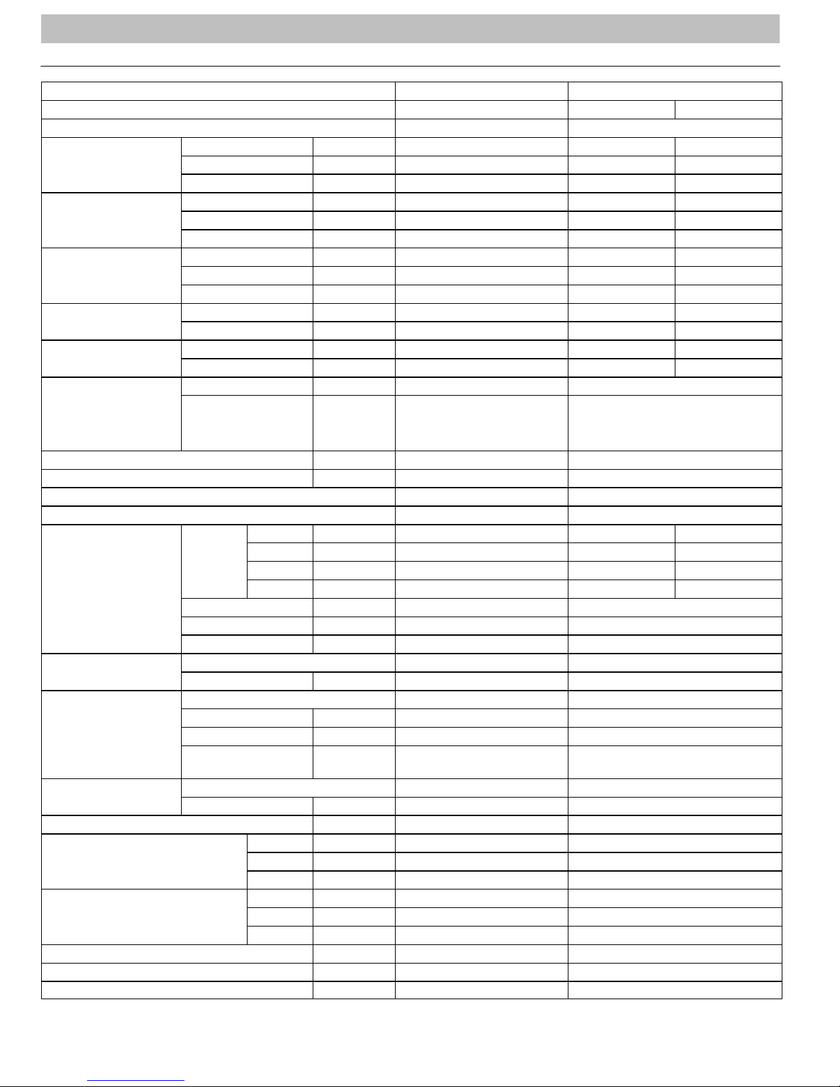
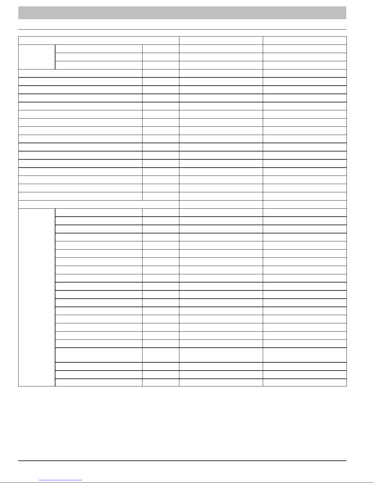
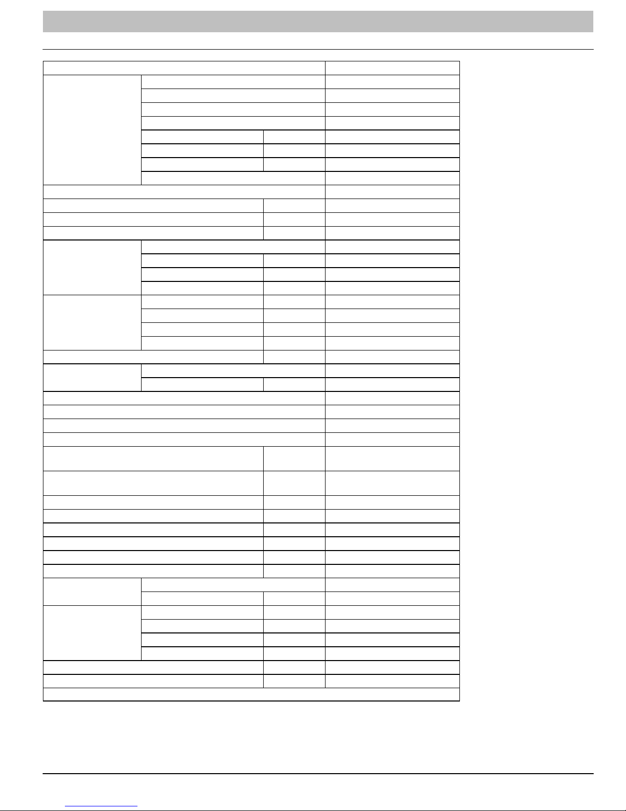
PRODUCT SPECIFICATIONS
Model − Indoor Unit DLF4AH09J1A DLF4HH09J1A
Function Cooling Cooling Heating
Rated Voltage 115V 115V
Frequency
(Inverter different
Compressor speed)
Total Capacity
(Inverter different
Compressor speed)
Power Input
(Inverter different
Compressor speed)
Rated Input
Rated Current
Air Volume
High Hz 70 70 63
Standard Hz 41 41 44
Low Hz 15 15 15
High W/Btuh 3100 / 10600 3100 / 10600 3250 / 11100
Standard W/Btuh 2650 / 9000 2650 / 9000 2820 / 9500
Low W/Btuh 1300 / 4435 1300 / 4435 930 / 3200
High W 1050 1050 1100
Standard W 634 634 700
Low W 180 180 220
High W 1050 1050 1100
Standard W 634 634 700
High A 16.8 16.8 17.0
Standard A 7.0 7.0 7.5
CFM 370 370
Dehumidifying Volume I/h 0.8 0.8
EER / C.O.P 14.2 14.2
SEER / HSPF 22 22 / 9.8
Indoor Unit DLF4AH09J1A DLF4HH09J1A
SH r/min 1260 1260 1320
Speed
Fan Motor
Output W 20 20
Capacitor mF 4.0 4.0
RLA A 0.38 0.38
Fan
Evaporator
Swing Motor
Fuse A 3.15 3.15
Sound Pressure Level
Sound Pressure Level
Dimension (WxHxD) Inch 33 x 11 x 7 33 x 11 x 7
Dimension of Package (WxHxD) Inch 36 x 14 x 10 36 x 14 x 10
Net Weight / Gross Weight Inch 29 / 38 29 / 38
Type Cross Flow Fan Cross Flow Fan
Diameter−Length Inch f3.6x25.4 f3.6x25.4
Pipe Diameter Inch f0.3 f0.3
Row−Fin Gap Inch 2−0.06 2−0.06
Coil length (I) x height
(H) x coil width (L)
Model MP24AA MP24AA
Output W 2.4 2.4
H r/min 1050 1050 1200
M r/min 920 920 1100
L r/min 730 730 950
Aluminum Fin Copper Tube Aluminum Fin Copper Tube
Inch 25.4 x 10.5 x 1 25.4 x 10.5 x 1
H dB (A) 34 34
M dB (A) 30 30
L dB (A) 26 26
H dB (A) 44 44
M dB (A) 40 40
L dB (A) 36 36
2 421 01 9204 00
Page 3
SERVICE MANUAL R−410A Ductless Split System: DLF4(A/H), DLC4(A/H)
PRODUCT SPECIFICATIONS (Cont.)
Model − Outdoor Unit DLF4AV09J1A DLF4HV09J1A
Manufacturer Sanyo Sanyo
Model C−6RZ110H1A C−6RZ110H1A
Type Twin Rotary Twin Rotary
Compressor
Throttling Method
Starting Method Transducer Starting Transducer Starting
Working Temperature Range °F 55 ~ 115 55 ~ 11 5 5 ~ 24
Heat Exchanger Coil
Coil Length (I) x Height (H) x Width (L) inch 31.5 x 19.5 x.05 31.5 x 19.5 x.05
Fan Motor
Air Flow Volume of Outdoor Unit Ft3/min 1118 1118
Fan
Defrosting Method / /
Climate Type T1 T1
Isolation I I
Moisture Protection IP24 IP24
Permissible Excessive Operating Pressure for
the Discharge Side
Permissible Excessive Operating Pressure for
the Suction Side
Sound Pressure Level DB (A) ≤50 ≤50
Sound Power Level DB (A) ≤63 ≤63
Dimensions (WxHxD) inch 33 X 21 X 12.6 33 X 21 X 12.6
Dimensions of Package (WxHxD) inch 34.5 X 22.8 X 14.2 34.5 X 22.8 X 14.2
Net Weight / Gross Weight Lbs. 96 / 110 96 / 110
Refrigerant
Connection Pipe
Max. Interunit height Difference Ft. 33 33
Max. Interunit Piping Length Ft. 66 66
* The above data is subject to change without notice. Please refer to the nameplate of the unit.
L.R.A. A 33 33
R.L.A. A 4.59 / 2.81 4.59 / 2.81
Power Input W 775 / 735 775 / 735
Overload Protectorr Int11I−3979 Int11I−3979
Electronic Expansion Valve
Throttling
Coil
Pipe Diameter inch f0.3 f0.3
Rows−Fin Gap inch 2−0.06 2−0.06
Speed rpm 900 / 650 900 / 650 900
Output of Fan Motor W 40 40
R.L.A. A 0.17 0.17
Capacitor mF / /
Type Axial Fan Axial Fan
Diameter inch 15.7 15.7
Mpa 3.8 3.8
Mpa 1.2 1.2
Name of Refrigerant R410A R410A
Weight Oz. 42 42
Length (m) Ft. 16 16
Gas Additional
Charge
Liquid Pipe Diameter inch f1/4 f1/4
Gas Pipe Diameter inch f3/8 f3/8
Oz/ft 1.1613 1.1613
Aluminum Fin−Copper
Tube
Electronic Expansion Valve Throttling
Aluminum Fin−Copper Tube
421 08 9204 00 3
Page 4
SERVICE MANUAL R−410A Ductless Split System: DLF4(A/H), DLC4(A/H)
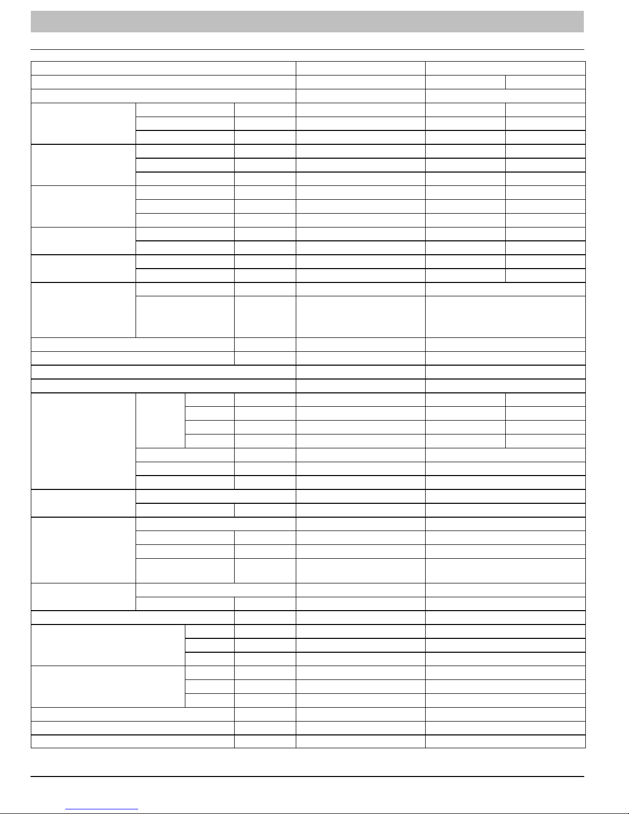
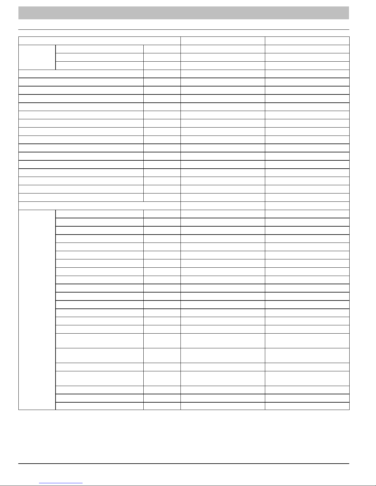
PRODUCT SPECIFICATIONS
Model − Indoor Unit DLF4AH12J1A DLF4HH12J1A
Function Cooling Cooling Heating
Rated Voltage 115V 115V
Frequency
(Inverter different
Compressor speed)
Total Capacity
(Inverter different
Compressor speed)
Power Input
(Inverter different
Compressor speed)
Rated Input
Rated Current
Air Volume
High Hz 70 70 63
Standard Hz 41 41 44
Low Hz 15 15 15
High W/Btuh 3100 / 10600 3100 / 10600 3250 / 11100
Standard W/Btuh 2650 / 9000 2650 / 9000 2820 / 9500
Low W/Btuh 1300 / 4435 1300 / 4435 930 / 3200
High W 1050 1050 1100
Standard W 634 634 700
Low W 180 180 220
High W 1050 1050 1100
Standard W 634 634 700
High A 16.8 16.8 17.0
Standard A 7.0 7.0 7.5
CFM 370 370
Dehumidifying Volume I/h 0.8 0.8
EER / C.O.P 14.2 14.2
SEER / HSPF 22 22 / 9.8
Indoor Unit DLF4AH12J1A DLF4HH12J1A
SH r/min 1260 1260 1320
Speed
Fan Motor
Output W 20 20
Capacitor mF 4.0 4.0
RLA A 0.38 0.38
Fan
Evaporator
Swing Motor
Fuse A 3.15 3.15
Sound Pressure Level
Sound Pressure Level
Dimension (WxHxD) Inch 33 x 11 x 7 33 x 11 x 7
Dimension of Package (WxHxD) Inch 36 x 14 x 10 36 x 14 x 10
Net Weight / Gross Weight Inch 29 / 38 29 / 38
Type Cross Flow Fan Cross Flow Fan
Diameter−Length Inch f3.6x25.4 f3.6x25.4
Pipe Diameter Inch f0.3 f0.3
Row−Fin Gap Inch 2−0.06 2−0.06
Coil length (I) x height
(H) x coil width (L)
Model MP24AA MP24AA
Output W 2.4 2.4
H r/min 1050 1050 1200
M r/min 920 920 1100
L r/min 730 730 950
Aluminum Fin Copper Tube Aluminum Fin Copper Tube
Inch 25.4 x 10.5 x 1 25.4 x 10.5 x 1
H dB (A) 34 34
M dB (A) 30 30
L dB (A) 26 26
H dB (A) 44 44
M dB (A) 40 40
L dB (A) 36 36
4 421 08 9204 00
Page 5

SERVICE MANUAL R−410A Ductless Split System: DLF4(A/H), DLC4(A/H)
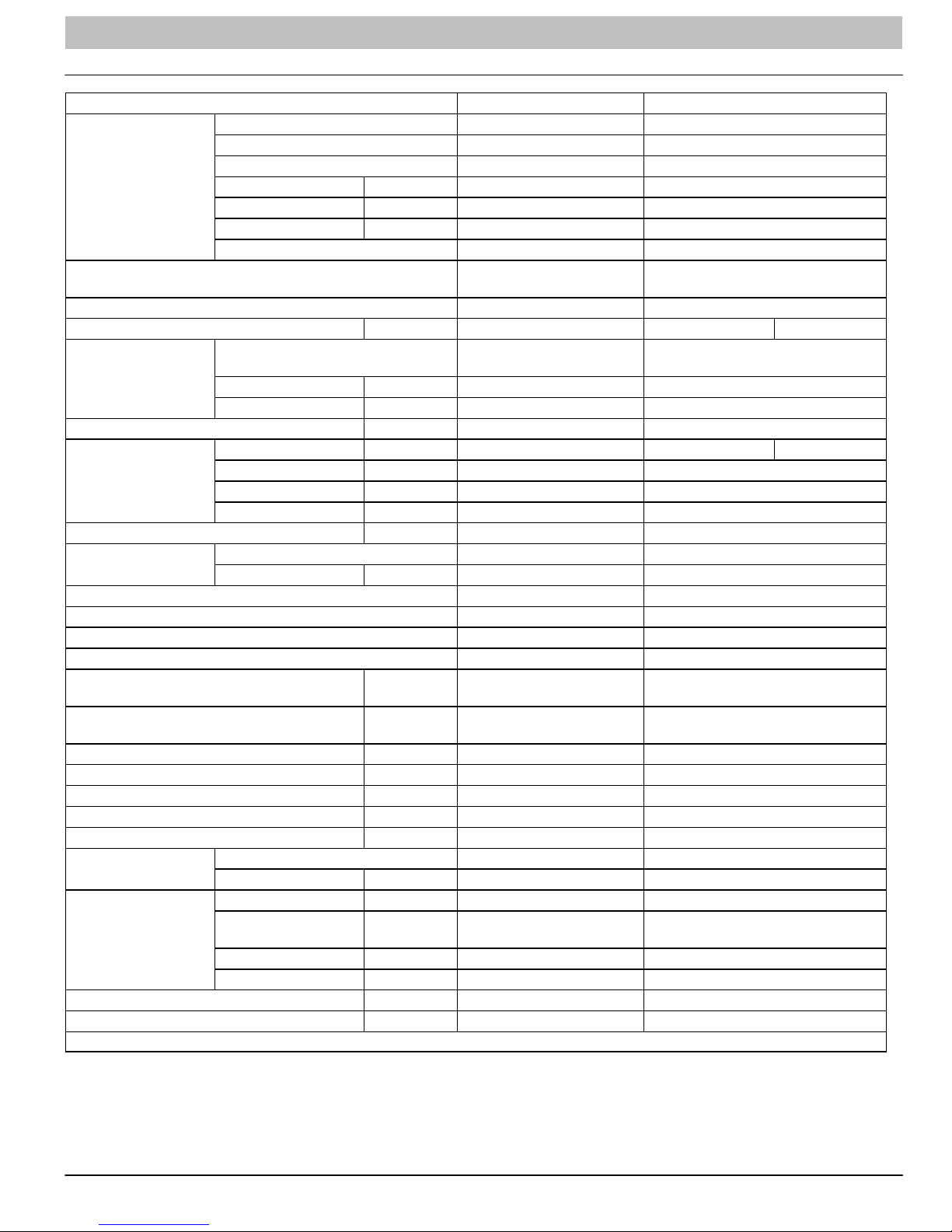
PRODUCT SPECIFICATIONS (Cont.)
Model − Outdoor Unit DLC4AV12J1A DLC4HV12J1A
Manufacturer Sanyo Sanyo
Model C−6RZ110H1A C−6RZ110H1A
Type Twin Rotary Twin Rotary
Compressor
Throttling Method
Starting Method Transducer Starting Transducer Starting
Working Temperature Range °F 55 ~ 115 55 ~ 11 5 5 ~ 75
Heat Exchanger Coil
Coil Length (I) x Height (H) x Width (L) inch 30.2 x 20 x0.9 30.2 x 20 x0.9
Fan Motor
Air Flow Volume of Outdoor Unit Ft3/min 111 8 1118
Fan
Defrosting Method / Auto Defrost
Climate Type T1 T1
Isolation I I
Moisture Protection IP24 IP24
Permissible Excessive Operating Pressure for
the Discharge Side
Permissible Excessive Operating Pressure for
the Suction Side
Sound Pressure Level DB (A) ≤53 ≤53
Sound Power Level DB (A) ≤65 ≤65
Dimensions (WxHxD) inch 33 X 21 X 12.6 33 X 21 X 12.6
Dimensions of Package (WxHxD) inch 34.5 X 22.8 X 14.2 34.5 X 22.8 X 14.2
Net Weight / Gross Weight Lbs. 107 / 118 107 / 118
Refrigerant
Connection Pipe
Max. Interunit height Difference Ft. 33 33
Max. Interunit Piping Length Ft. 66 66
* The above data is subject to change without notice. Please refer to the nameplate of the unit.
L.R.A. A 33 33
R.L.A. A 4.59 / 2.81 4.59 / 2.81
Power Input W 775 / 735 775 / 735
Overload Protectorr Int11I−3979 Int11I−3979
Electronic Expansion Valve
Throttling
Coil
Pipe Diameter inch f0.4 f0.4
Rows−Fin Gap inch 2−0.06 2−0.06
Speed rpm 900 / 680 900 / 680 900
Output of Fan Motor W 40 40
R.L.A. A 0.17 0.17
Capacitor mF / /
Type Axial Fan Axial Fan
Diameter inch 15.7 15.7
Mpa 3.8 3.8
Mpa 1.2 1.2
Name of Refrigerant R410A R410A
Weight Oz. 45.5 45.5
Length (m) Ft. 16 16
Gas Additional
Charge
Liquid Pipe Diameter inch f1/4 f1/4
Gas Pipe Diameter inch f3/8 f3/8
Oz/ft 1.1613 1.1613
Aluminum Fin−Copper
Tube
Electronic Expansion Valve Throttling
Aluminum Fin−Copper Tube
421 08 9204 00 5
Page 6

SERVICE MANUAL R−410A Ductless Split System: DLF4(A/H), DLC4(A/H)
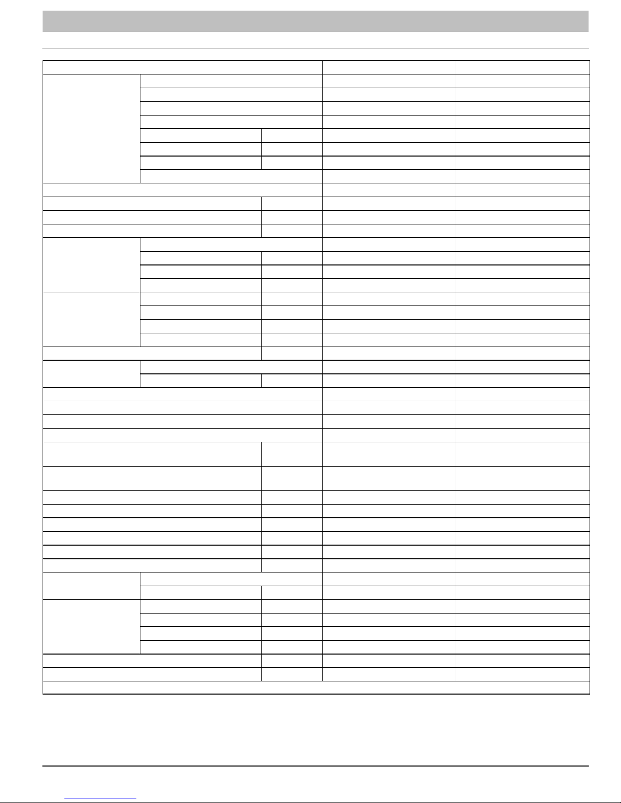
PRODUCT SPECIFICATIONS (Cont.)
Model DLC4AV12K1A DLC4HV12K1A
Power
Supply
Power Supply Mode Outdoor Outdoor
Cooling Capacity (Min − Max) Btu/h 12000 (3100−13000) 12000 (3100−13000)
Heating Capacity (Min. − Max) Btu/h N/A 13000 (2400−14000)
Cooling Power Input (Min. − Max.) W 1000 (365−1080) 1000 (365−1080)
Heating Power Input (Min. − Max.) W N/A 1000 (340−1360)
Cooling Current Input A 4.5 4.5
Heating Current Input A N/A 5.2
Rated Input W 1500 1500
Rated Current A 15 15
Air Flow Volume (S/H/M/L) CFM 335/277/253/218 335/277/253/218
Dehumidifying Volume Pint/h 2.959 2.959
EER Btu/hW 12 12
COP Btu/hW N/A 10.8
SEER 20 20
HSPF N/A 9.2
Application Area m
Model − Indoor Unit DLF4AH12K1A DLF4HH12K1A
Indoor Unit
Rated Voltage V~ 208/230 208/230
Rated Frequency Hz 60 60
Phases 1 1
2
Fan Type Cross−flow Cross−flow
Fan Diameter Length (DXL) inch f3.6x25.4 f3.6x25.4
Cooling Speed (S/H/M/L) r/min 1330/1100/950/750 1330/1100/950/750
Heating Speed (S/H/M/L) r/min N/A 1350/1170/1050/950
Fan Motor Power Output W 20 20
Fan Motor RLA A 0.2 0.2
Fan Motor Capacitor mF 1 1
Evaporator Form W Aluminum Fin−Copper Tube Aluminum Fin−Copper Tube
Evaporator Pipe Diameter inch f0.27 f0.27
Evaporator Row−fin Gap inch 2−0.05 2−0.05
Evaporator Coil Length (LxDxW) inch 22.8x1x10.4 22.8x1x10.4
Swing Motor Model MP24AA MP24AA
Swing Motor Power Output W 2.4 2.4
Fuse Current A 3.15 3.15
Sound Pressure Level (S/H/M/L) dB (A) 42/39/36/33 42/39/36/33
Sound Power Level (S/H/M/L) dB (A) 52/49/46/43 52/49/46/43
Dimension (WxHxD) inch 33.3X10.8X7 33.3X10.8X7
Dimension of Carton Box
(WxHxD)
Dimension of Package (WxHxD) inch 36X10.1X14.6 36X10.1X14.6
Net Weight lb 22 22
Gross Weight lb 28.7 28.7
inch 36X10X14 36X10X14
16−24 16−24
6 421 08 9204 00
Page 7

SERVICE MANUAL R−410A Ductless Split System: DLF4(A/H), DLC4(A/H)
PRODUCT SPECIFICATIONS (Cont.)
Model − Outdoor Unit DLC4AV12K1A DLC4HV12K1A
Manufacturer Mitsubishi Mitsubishi
Model KNB092FTAMC KNB092FTAMC
Oil FV50S FV50S
Compressor
Throttling Method Electronic Expansion Valve Electronic Expansion Valve
Set Temperature Range °F 60.8 ~ 86 60.8 ~ 86
Cooling Operation Ambient Temperature Range °F 0.4 ~ 109.4 0.4 ~ 109.4
Heating Operation Ambient Temperature Range °F N/A −5 ~ 75.0
Condenser
Fan Motor
Air Flow Volume of Outdoor Unit CFM 941.6 941.6
Fan
Defrosting Method N/A Automatic Defrosting
Climate Type T1 T1
Isolation I I
Moisture Protection IP24 IP24
Permissible Excessive Operating Pressure for the
Discharge Side
Permissible Excessive Operating Pressure for the
Suction Side
Sound Pressure Level (H/M/L) DB (A) 52/−/− 52/−/−
Sound Power Level (H/M/L) DB (A) 62/−/− 62/−/−
Dimensions (WxHxD) inch 33.4x23.2x12.6 33.4x23.2x12.6
Dimensions of Carton Box (WxHxD) inch 34.5x14.2x24.8 34.5x14.2x24.8
Dimensions of Package (WxHxD) inch 34.7x14.3x25.4 34.7x14.3x25.4
Net Weight / Gross Weight Lbs. 88.2 / 97.02 88.2 / 97.02
Refrigerant
Connection Pipe
Max. Interunit height Difference Ft. 33 33
Max. Interunit Piping Length Ft. 66 66
* The above data is subject to change without notice. Please refer to the nameplate of the unit.
Type Rotary Rotary
L.R.A. A 13.8 13.8
R.L.A. A 3.2 3.2
Power Input W 860 860
Overload Protector INT11L−6578 INT11L−6578
Form Aluminum Fin−copper Tube Aluminum Fin−copper Tube
Pipe Diameter inch f0.37 f0.37
Rows−Fin Gap inch 2−0.05 2−0.05
Coil Length (LxDxW) inch 29.4x1.7x22 29.4x1.7x22
Speed rpm 680 / 900 680 / 900
Output of Fan Motor W 30 30
R.L.A. A 0.13 0.13
Capacitor mF N/A N/A
Type Axial Flow Axial Flow
Diameter inch 15.748 15.748
Mpa 4.3 4.3
Mpa 2.5 2.5
Name of Refrigerant R410A R410A
Weight Oz. 45.864 45.864
Length inch 25 25
Gas Additional Charge Oz/ft 0.53 0.7
Liquid Pipe Outer Diameter inch 1/4 1/4
Gas Pipe Outer Diameter inch 3/8 3/8
421 08 9204 00 7
Page 8
SERVICE MANUAL R−410A Ductless Split System: DLF4(A/H), DLC4(A/H)
PRODUCT SPECIFICATIONS (Cont.)
Model DLC4AV18K1A DLC4HV18K1A
Power
Supply
Power Supply Mode Outdoor Outdoor
Cooling Capacity (Min − Max) Btu/h 18000 (5970−22350) 18000 (5970−22350)
Heating Capacity (Min. − Max) Btu/h N/A 19800 (4100−22000)
Cooling Power Input (Min. − Max.) W 1500 (300−2650) 1500 (300−2650)
Heating Power Input (Min. − Max.) W N/A 1650 (335−2750)
Cooling Current Input A 6.65 6.65
Heating Current Input A N/A 7.32
Rated Input W 2650 2750
Rated Current A 11.757 12.201
Air Flow Volume (S/H/M/L) CFM 500/459/383/324 500/459/383/324
Dehumidifying Volume Pint/h 0.852 0.852
EER Btu/hW 12 12
COP Btu/hW N/A 12
SEER 18 18
HSPF N/A 10
Application Area m
Model − Indoor Unit DLF4AH18K1A DLF4HH18K1A
Indoor Unit
Rated Voltage V~ 208/230 208/230
Rated Frequency Hz 60 60
Phases 1 1
2
Fan Type Cross−flow Cross−flow
Fan Diameter Length (DXL) inch f3.86x28 f3.86x28
Cooling Speed (S/H/M/L) r/min 1500/1200/1050/900 1500/1200/1050/900
Heating Speed (S/H/M/L) r/min N/A 1500/1250/1150/1050
Fan Motor Power Output W 20 20
Fan Motor RLA A 0.32 0.32
Fan Motor Capacitor mF 1.5 1.5
Evaporator Form W Aluminum Fin−Copper Tube Aluminum Fin−Copper Tube
Evaporator Pipe Diameter inch f0.27 f0.27
Evaporator Row−fin Gap inch 2−0.05 2−0.05
Evaporator Coil Length (LxDxW) inch 28x1x12 28x1x12
Swing Motor Model MP28VB MP28VB
Swing Motor Power Output W 2.5 2.5
Fuse Current A 3.15 3.15
Sound Pressure Level (S/H/M/L) dB (A) 49/44/40/35 49/44/40/35
Sound Power Level (S/H/M/L) dB (A) 59/54/50/45 59/54/50/45
Dimension (WxHxD) inch 37X11.7X7.9 37X11.7X7.9
Dimension of Carton Box
(WxHxD)
Dimension of Package (WxHxD) inch 39.7X11.2X15 39.7X11.2X15
Net Weight lb 28.665 28.665
Gross Weight lb 37.485 37.485
inch 39.6X11.1X14.4 39.6X11.1X14.4
27−42 27−42
8 421 08 9204 00
Page 9

SERVICE MANUAL R−410A Ductless Split System: DLF4(A/H), DLC4(A/H)
PRODUCT SPECIFICATIONS (Cont.)
Model − Outdoor Unit DLC4AV18K1A DLC4HV18K1A
Manufacturer Mitsubishi Mitsubishi
Model SNB130FGAMC SNB130FGAMC
Oil FV50S−PVE FV50S−PVE
Compressor
Throttling Method Electronic Expansion Valve Electronic Expansion Valve
Set Temperature Range °F 61 ~ 86 61 ~ 86
Cooling Operation Ambient Temperature Range °F 14 ~ 109.0 14 ~ 109.0
Heating Operation Ambient Temperature Range °F N/A 19.4 − 75.0
Condenser
Fan Motor
Air Flow Volume of Outdoor Unit CFM 1883.2 1883.2
Fan
Defrosting Method N/A Automatic Defrosting
Climate Type T1 T1
Isolation I I
Moisture Protection IP24 IP24
Permissible Excessive Operating Pressure for the
Discharge Side
Permissible Excessive Operating Pressure for the
Suction Side
Sound Pressure Level (H/M/L) DB (A) 55/−/− 55/−/−
Sound Power Level (H/M/L) DB (A) 65/−/− 65/−/−
Dimensions (WxHxD) inch 37.6x27.6x15.6 37.6x27.6x15.6
Dimensions of Carton Box (WxHxD) inch 40.4x18x29 40.4x18x29
Dimensions of Package (WxHxD) inch 40.5x18x29.5 40.5x18x29.5
Net Weight / Gross Weight Lbs. 99.225 / 110.25 99.225 / 110.25
Refrigerant
Connection Pipe
Max. Interunit height Difference Ft. 33 33
Max. Interunit Piping Length Ft. 82 82
* The above data is subject to change without notice. Please refer to the nameplate of the unit.
Type Rotary Rotary
L.R.A. A 13.8 13.8
R.L.A. A 4.1 4.1
Power Input W 1200 1200
Overload Protector INT11L−6578 INT11L−6578
Form Aluminum Fin−copper Tube Aluminum Fin−copper Tube
Pipe Diameter inch f0.37 f0.37
Rows−Fin Gap inch 2−0.05 2−0.05
Coil Length (LxDxW) inch 33x1.5x26 33x1.5x26
Speed rpm 800 800
Output of Fan Motor W 60 60
R.L.A. A 0.28 0.28
Capacitor mF N/A N/A
Type Axial Flow Axial Flow
Diameter inch 20.472 20.472
Mpa 4.3 4.3
Mpa 2.5 2.5
Name of Refrigerant R410A R410A
Weight Oz. 49.392 49.392
Length inch 25 25
Gas Additional Charge Oz/ft 0.2 0.2
Liquid Pipe Outer Diameter inch 1/4 1/4
Gas Pipe Outer Diameter inch 1/2 1/2
421 08 9204 00 9
Page 10

SERVICE MANUAL R−410A Ductless Split System: DLF4(A/H), DLC4(A/H)
PRODUCT SPECIFICATIONS (Cont.)
Model DLC4AV24K1A DLC4HV24K1A
Power
Supply
Power Supply Mode Outdoor Outdoor
Cooling Capacity (Min − Max) Btu/h 21400 (9600−25000) 21400 (9600−25000)
Heating Capacity (Min. − Max) Btu/h N/A 23000 (4300−26000)
Cooling Power Input (Min. − Max.) W 1780 (500−2650) 1780 (500−2650)
Heating Power Input (Min. − Max.) W N/A 2100 (400−2750)
Cooling Current Input A 7.941 7.941
Heating Current Input A N/A 9.317
Rated Input W 2650 2750
Rated Current A 11.757 12.201
Air Flow Volume (S/H/M/L) CFM 589/471/412/353 589/471/412/353
Dehumidifying Volume Pint/h 1.183 1.183
EER Btu/hW 12 12
COP Btu/hW N/A 10.95
SEER 18 18
HSPF N/A 10
Application Area m
Model − Indoor Unit DLF4AH24K1A DLF4HH24K1A
Indoor Unit
Rated Voltage V~ 208/230 208/230
Rated Frequency Hz 60 60
Phases 1 1
2
Fan Type Cross−flow Cross−flow
Fan Diameter Length (DXL) inch f3.86x30 f3.86x30
Cooling Speed (S/H/M/L) r/min 1500/1200/1050/900 1500/1200/1050/900
Heating Speed (S/H/M/L) r/min N/A 1450/1150/1020/950
Fan Motor Power Output W 260 260
Fan Motor RLA A 0.24 0.24
Fan Motor Capacitor mF N/A N/A
Evaporator Form W Aluminum Fin−Copper Tube Aluminum Fin−Copper Tube
Evaporator Pipe Diameter inch f0.27 f0.27
Evaporator Row−fin Gap inch 2−0.06 2−0.06
Evaporator Coil Length (LxDxW) inch 30x1x15.5 30x1x15.5
Swing Motor Model MP35XX MP35XX
Swing Motor Power Output W 3 3
Fuse Current A 3.15 3.15
Sound Pressure Level (S/H/M/L) dB (A) 53/45/41/37 53/45/41/37
Sound Power Level (S/H/M/L) dB (A) 63/55/51/47 63/55/51/47
Dimension (WxHxD) inch 39.7X12.4X8.6 39.7X12.4X8.6
Dimension of Carton Box
(WxHxD)
Dimension of Package (WxHxD) inch 42.4X15.7X12.9 42.4X15.7X12.9
Net Weight lb 35.28 35.28
Gross Weight lb 46.305 46.305
inch 42.2X15.5X12.3 42.2X15.5X12.3
27−42 27−42
10 421 08 9204 00
Page 11

SERVICE MANUAL R−410A Ductless Split System: DLF4(A/H), DLC4(A/H)
PRODUCT SPECIFICATIONS (Cont.)
Model − Outdoor Unit DLC4AV24K1A DLC4HV24K1A
Manufacturer Mitsubishi Mitsubishi
Model SNB150FGAMC SNB150FGAMC
Oil FV50S−PVE FV50S−PVE
Compressor
Throttling Method Electronic Expansion Valve Electronic Expansion Valve
Set Temperature Range °F 61 ~ 86 61 ~ 86
Cooling Operation Ambient Temperature Range °F 5 ~ 109.0 5 ~ 109.0
Heating Operation Ambient Temperature Range °F N/A 19.4 − 75.0
Condenser
Fan Motor
Air Flow Volume of Outdoor Unit CFM 2354 2354
Fan
Defrosting Method N/A N/A
Climate Type T1 T1
Isolation I I
Moisture Protection IP24 IP24
Permissible Excessive Operating Pressure for the
Discharge Side
Permissible Excessive Operating Pressure for the
Suction Side
Sound Pressure Level (H/M/L) DB (A) 56/−/− 56/−/−
Sound Power Level (H/M/L) DB (A) 66/−/− 66/−/−
Dimensions (WxHxD) inch 38.6x31.1x16.8 38.6x31.1x16.8
Dimensions of Carton Box (WxHxD) inch 42.5x19x33 42.5x19x33
Dimensions of Package (WxHxD) inch 42.6x19x33.7 42.6x19x33.7
Net Weight / Gross Weight Lbs. 119 / 132 119 / 132
Refrigerant
Connection Pipe
Max. Interunit height Difference Ft. 33 33
Max. Interunit Piping Length Ft. 82 82
* The above data is subject to change without notice. Please refer to the nameplate of the unit.
Type Rotary Rotary
L.R.A. A 18.5 18.5
R.L.A. A 4.9 4.9
Power Input W 1420 1420
Overload Protector INT11L−6578 INT11L−6578
Form Aluminum Fin−copper Tube Aluminum Fin−copper Tube
Pipe Diameter inch f0.27 f0.27
Rows−Fin Gap inch 2−0.05 2−0.05
Coil Length (LxDxW) inch 38x1.5x29 38x1.5x29
Speed rpm 800 800
Output of Fan Motor W 90 90
R.L.A. A 1.1 1.1
Capacitor mF 4 4
Type Axial Flow Axial Flow
Diameter inch 21.732 21.732
Mpa 4.3 4.3
Mpa 2.5 2.5
Name of Refrigerant R410A R410A
Weight Oz. 56.448 56.448
Length inch 25 25
Gas Additional Charge Oz/ft 0.2 0.2
Liquid Pipe Outer Diameter inch 1/4 1/4
Gas Pipe Outer Diameter inch 5/8 5/8
421 08 9204 00 11
Page 12
SERVICE MANUAL R−410A Ductless Split System: DLF4(A/H), DLC4(A/H)
PRODUCT SPECIFICATIONS (Cont.)
Model DLF4HH30K1A DLF4HH36K1A
Power
Supply
Power Supply Mode Outdoor Outdoor
Cooling Capacity (Min − Max) Btu/h 28000 (9500−30000) 33600 (7400−36000)
Heating Capacity (Min. − Max) Btu/h 28400 (10000−33000) 34600 (1500−36000)
Cooling Power Input (Min. − Max.) W 2780 (350−3400) 3650 (450−3800)
Heating Power Input (Min. − Max.) W 2870 (450−3300) 3560 (560−3700)
Cooling Current Input A 12.1 16.6
Heating Current Input A 12.5 9.21
Rated Input W 3475 4000
Rated Current A 16.7 18.2
Air Flow Volume (S/H/M/L) CFM −/706/677/647/− −/824/706/677/−
Dehumidifying Volume Pint/h 1.42 1.166
EER Btu/hW 10.7 9.21
COP Btu/hW 9.93 9.72
SEER 16 16
HSPF 8.2 8.2
Application Area m
Model − Indoor Unit DLC4HV30K1A DLC4HH36K1A
Indoor Unit
Rated Voltage V~ 208/230 208/230
Rated Frequency Hz 60 60
Phases 1 1
2
Fan Type Cross−flow Cross−flow
Fan Diameter Length (DXL) inch f4.25x20.58X2 f4.25x20.58X2
Cooling Speed (SH/H/ML/SL) r/min −/1410/1280/1200/− −1550/1400/1300/−
Heating Speed (SH/H/ML/SL) r/min −/1410/1280/1200/− −1550/1400/1300/−
Fan Motor Power Output W 40 60
Fan Motor RLA A 0.4 0.47
Fan Motor Capacitor mF 3.5 3.5
Input of Heater W − −
Evaporator Form W Aluminum Fin−Copper Tube Aluminum Fin−Copper Tube
Evaporator Pipe Diameter inch f11/40 f11/40
Evaporator Row−fin Gap inch 2−0.055 2−0.055
Evaporator Coil Length (LxDxW) inch 142.3x1x15 142.3x1x15
Swing Motor Model MP24BA MP24BA
Swing Motor Power Output W 2 2
Fuse Current A 3.15 3.15
Sound Pressure Level
(SH/H/M/L/SL)
Sound Power Level
(SH/H/M/L/SL)
Dimension (WxHxD) inch 53.1X12.8X10.0 53.1X12.8X10.0
Dimension of Carton Box
(WxHxD)
Dimension of Package (WxHxD) inch 56.7X16.6X14.0 56.7X16.6X14.0
Net Weight lb 44.1 44.1
Gross Weight lb 59.5 59.5
dB (A) −/57/54/46/− −57/56/53/−
dB (A) −/57/54/46/− −/69/66/63/−
inch 56.6X16.5X13.5 56.7X16.6X14.0
377−550 495−753
12 421 08 9204 00
Page 13
SERVICE MANUAL R−410A Ductless Split System: DLF4(A/H), DLC4(A/H)
PRODUCT SPECIFICATIONS (Cont.)
Model − Outdoor Unit DLC4HV30K1A DLC4HV36K1A
Manufacturer Zhuhai Landa Mitsubishi
Model QXAS−D23ZX090 TNB306FPGMCMC
Oil PVE (FV50S) FV50S
Compressor
Throttling Method Electronic Expansion Valve Electronic Expansion Valve
Set Temperature Range °F 61 ~ 86 61 ~ 86
Cooling Operation Ambient Temperature Range °F 5 ~ 109.0 5 ~ 109.0
Heating Operation Ambient Temperature Range °F 19.4−75.0 19.4 − 75.0
Condenser
Fan Motor
Air Flow Volume of Outdoor Unit CFM 2354 2589
Fan
Defrosting Method Automatic Defrosting Automatic Defrosting
Climate Type T1 T1
Isolation I I
Moisture Protection IP24 IP24
Permissible Excessive Operating Pressure for the
Discharge Side
Permissible Excessive Operating Pressure for the
Suction Side
Sound Pressure Level (H/M/L) DB (A) 62/−/− 65/−/−
Sound Power Level (H/M/L) DB (A) 72/−/− 75/−/−
Dimensions (WxHxD) inch 38.6x31.1x16.8 38.6x31.1x16.8
Dimensions of Carton Box (WxHxD) inch 42.5x19.1x33 42.5x19.1x33
Dimensions of Package (WxHxD) inch 42.6x19x33.7 42.6x19x33.7
Net Weight / Gross Weight Lbs. 154 / 163 161 / 170
Refrigerant
Connection Pipe
Max. Interunit height Difference Ft. 32.8 32.8
Max. Interunit Piping Length Ft. 98.4 98.4
* The above data is subject to change without notice. Please refer to the nameplate of the unit.
Type Rotary Rotary
L.R.A. A 40 67
R.L.A. A 12 13.5
Power Input W 2450 3010
Overload Protector INT11L−6233 CS01F272H01
Form Aluminum Fin−copper Tube Aluminum Fin−copper Tube
Pipe Diameter inch f01/3 f3/8
Rows−Fin Gap inch 2−0.055 2−0.055
Coil Length (LxDxW) inch 37.5x1.5x29.4 37x1.7x30
Speed rpm 830 900
Output of Fan Motor W 90 170
R.L.A. A 0.45 0.73
Capacitor mF N/A N/A
Type Axial Flow Axial Flow
Diameter inch f21.73 f21.73
PSI 551 551
PSI 174 174
Name of Refrigerant R410A R410A
Weight Oz. 84.7 91.7
Length inch 24.6 24.6
Gas Additional Charge Oz/ft 0.5 0.2
Liquid Pipe Outer Diameter inch f1/4 f1/4
Gas Pipe Outer Diameter inch f5/8 f5/8
421 08 9204 00 13
Page 14
SERVICE MANUAL R−410A Ductless Split System: DLF4(A/H), DLC4(A/H)
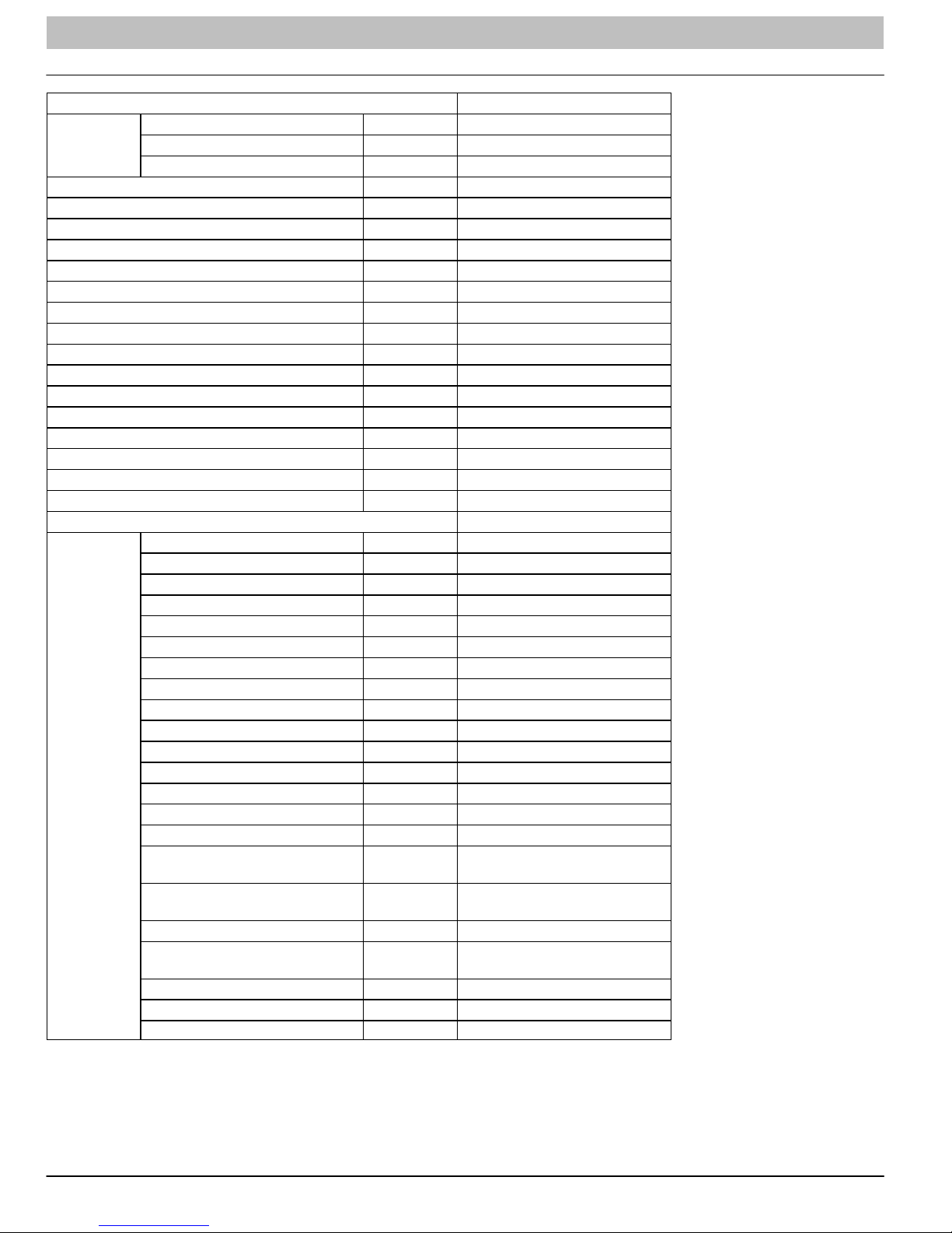
PRODUCT SPECIFICATIONS (Cont.)
Model DLF4AH36K1A
Power
Supply
Power Supply Mode Outdoor
Cooling Capacity (Min − Max) Btu/h 33600 (7400−36000)
Heating Capacity (Min. − Max) Btu/h N/A
Cooling Power Input (Min. − Max.) W 3650 (410−3800)
Heating Power Input (Min. − Max.) W N/A
Cooling Current Input A 15.9
Heating Current Input A N/A
Rated Input W 4200
Rated Current A 18.2
Air Flow Volume (S/H/M/L) CFM −/824/706/677/−
Dehumidifying Volume Pint/h 1.66
EER Btu/hW 9.21
COP Btu/hW N/A
SEER 16
HSPF N/A
Application Area m
Model − Indoor Unit DLF4AH36K1A
Indoor Unit
Rated Voltage V~ 208/230
Rated Frequency Hz 60
Phases 1
2
Fan Type Cross−flow
Fan Diameter Length (DXL) inch f4.25x20.58X2
Cooling Speed (SH/H/ML/SL) r/min −/1550/1400/12300/−
Heating Speed (SH/H/ML/SL) r/min N/A
Fan Motor Power Output W 60
Fan Motor RLA A 0.47
Fan Motor Capacitor mF 3.5
Input of Heater W N/A
Evaporator Form W Aluminum Fin−Copper Tube
Evaporator Pipe Diameter inch f11/40
Evaporator Row−fin Gap inch 2−0.055
Evaporator Coil Length (LxDxW) inch 142.3x1x15
Swing Motor Model MP24BA
Swing Motor Power Output W 2
Fuse Current A 3.15
Sound Pressure Level
(SH/H/M/L/SL)
Sound Power Level
(SH/H/M/L/SL)
Dimension (WxHxD) inch 53.1X12.8X10.0
Dimension of Carton Box
(WxHxD)
Dimension of Package (WxHxD) inch 56.7X16.6X14.0
Net Weight lb 44.1
Gross Weight lb 59.5
dB (A) −/59/56/53/−
dB (A) −/69/66/63/−
inch 56.6X16.5X13.5
495−753
14 421 08 9204 00
Page 15
SERVICE MANUAL R−410A Ductless Split System: DLF4(A/H), DLC4(A/H)
PRODUCT SPECIFICATIONS (Cont.)
Model − Outdoor Unit DLC4AV36K1A
Manufacturer Mitsubishi
Model TNB306FPGMCMC
Oil FV50S
Compressor
Throttling Method Capillary
Set Temperature Range °F 61 ~ 86
Cooling Operation Ambient Temperature Range °F 5 ~ 109.0
Heating Operation Ambient Temperature Range °F 19.4 − 75.0
Condenser
Fan Motor
Air Flow Volume of Outdoor Unit CFM 2589
Fan
Defrosting Method N/A
Climate Type T1
Isolation I
Moisture Protection IP24
Permissible Excessive Operating Pressure for the
Discharge Side
Permissible Excessive Operating Pressure for the
Suction Side
Sound Pressure Level (H/M/L) DB (A) 65/−/−
Sound Power Level (H/M/L) DB (A) 75/−/−
Dimensions (WxHxD) inch 38.6x31.1x16.7
Dimensions of Carton Box (WxHxD) inch 42.5x19.1x33.1
Dimensions of Package (WxHxD) inch 42.6x19.2x33.6
Net Weight / Gross Weight Lbs. 161 / 170
Refrigerant
Connection Pipe
Max. Interunit height Difference Ft. 32.8
Max. Interunit Piping Length Ft. 98.4
* The above data is subject to change without notice. Please refer to the nameplate of the unit.
Type Rotary
L.R.A. A 67
R.L.A. A 13.5
Power Input W 3010
Overload Protector CS01F272H01
Form Aluminum Fin−copper Tube
Pipe Diameter inch f3/8
Rows−Fin Gap inch 2−0.055
Coil Length (LxDxW) inch 37x1.7x30
Speed rpm 900
Output of Fan Motor W 170
R.L.A. A 0.73
Capacitor mF N/A
Type Axial Flow
Diameter inch f21.73
PSI 551
PSI 174
Name of Refrigerant R410A
Weight Oz. 91.7
Length inch 24.6
Gas Additional Charge Oz/ft 0.2
Liquid Pipe Outer Diameter inch f1/4
Gas Pipe Outer Diameter inch f5/8
421 08 9204 00 15
Page 16
SERVICE MANUAL R−410A Ductless Split System: DLF4(A/H), DLC4(A/H)
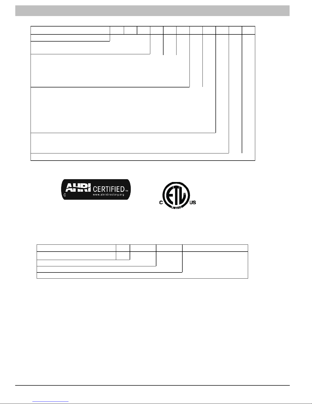
MODEL NOMENCLATURE
MODEL SERIES
Position Number 1 2 3 4 5 6 7 8 9 10 11
DLC = Outdoor
DLF = Indoor Outdoor/Indoor
4AV = AC Outdoor
4AH = AC Indoor
4HV = HP Outdoor
4HH = HP Indoor
09 = 9k BTU
12 = 12k BTU
18 = 18k BTU
24 = 24k BTU
30 = 30k BTU
36 = 36k BTU
J = 115−1−60
K = 208/230−1−60
1A Factory Designation
D L C 4 A V 0 9 J 1 A
Type
Size
Voltage
Use of the AHRI Certified TM Mark indicates a
manufacturer’s participation in the program. For
verification of certification for individual products,
go to www.ahridirectory.org .
SERIAL NUMBER NOMENCLATURE
Position Number 1 2 3 4 5 6 7 8 9 10
Serial Number
Year
Week
Sequential Digits Unique for Each Factory
V 1 0 2 2 1 2 3 4 5
16 421 08 9204 00
Page 17
SERVICE MANUAL R−410A Ductless Split System: DLF4(A/H), DLC4(A/H)
STANDARD FEATURES AND ACCESSORIES
Ease of Operation
Mounting Brackets S
Low Voltage Connections S
Comfort Features
Microprocessor Controls S
Wireless Remote Control S
Rapid Cooling/Heating S
Automatic Air Sweep S
Cold Blow Prevention S
Continuous Fan S
Auto Restart Feature S
Memory Function S
Auto Changeover S
Energy Saving Features
Inverter Driven Compressor S
Sleep Mode S
24 Hour Stop/Start Timer* S
Safety and Reliability
Indoor Unit Freeze Protection S
3 Minute Compressor Time Delay S
High Compressor Discharge Temperature S
Low Voltage Protection S
Compressor Overload Protection S
Compressor Over Current Protection S
IPM Module Protection S
Ease of Service and Maintenance
Cleanable Filters S
Diagnostic LED’s ON Outdoor Board S
Error Messages Displayed Front Panel S
Application Flexibility
Condensate Pump A
Low Ambient Heating and Cooling on most models A
Standard Warranty
7 Year Compressor Limited Warranty S
5 Year Parts Limited Warranty S
Extended Warranty
6 −10 Year Compressor Only O
2 − 6 Year Parts Only O
2 − 6 Year Parts Only; 1 − 6 Year Labor O
2 − 6 Year Parts Only; 6 − 10 Year Compressor Only;
1 − 6 Year Labor
Legend
S = Standard
A = Accessory
O = Optional
* Sizes 09, 18, & 24K have a clock.
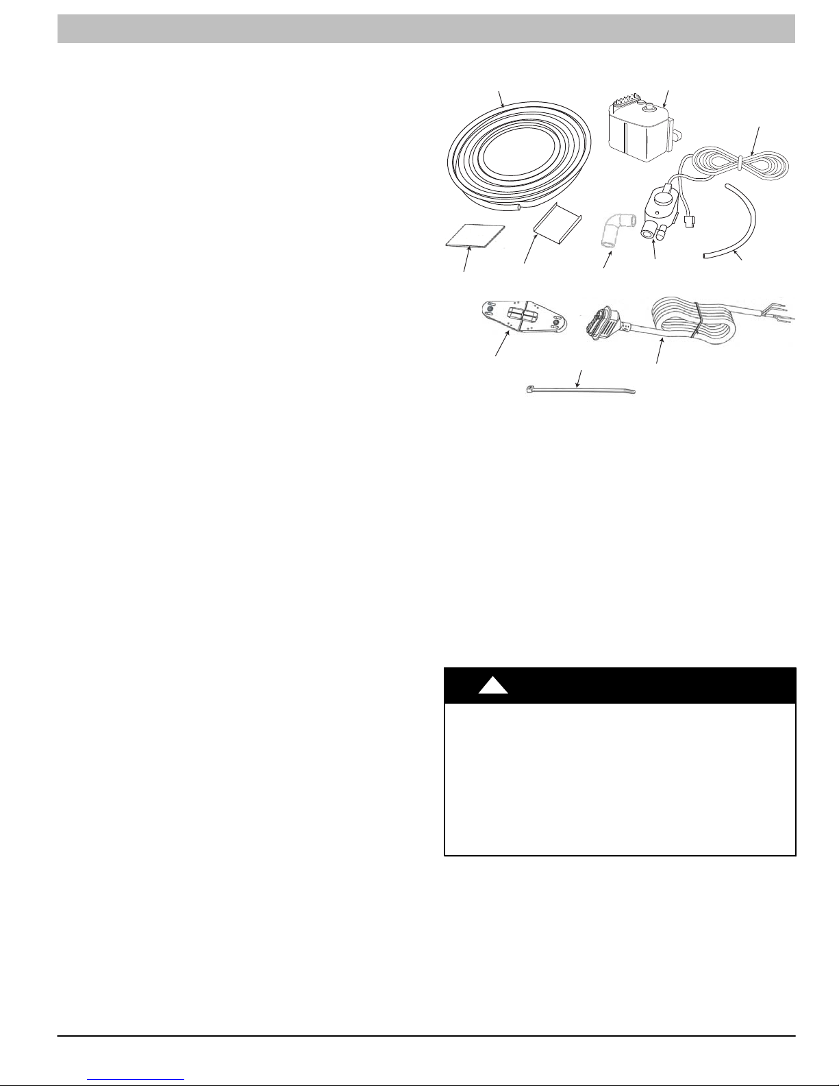
16’ Transparent
Suction Discharge Tubing
Adhesive
Mounting Bracket
Detection Unit
Mounting Bracket
5/8” Rubber Elbow
Wire Ties (6)
Figure 1 - Accessory Condensate Pump Kit
Table 1 − Accessory Condensate Pump Kit Contents
Item Qty.
16 ft Transparent Suction/Discharge Tubing 1
Condensate Pump Assembly 1
Low voltage Power Cord 1
Transparent Detection Unit Vent Tubing 1
Power Cable 1
Wire Ties 6
Wall Mount Bracket 1
Adhesive 1
Detection Unit Mounting Bracket 1
⅝−in Rubber Elbow 1
Detection Unit 1
!
ELECTRICAL SHOCK HAZARD
O
Failure to follow this warning could result in personal injury
or death.
Before installing, modifying, or servicing system, main
electrical disconnect switch must be in the OFF position.
Ensure power is disconnected to the fan coil unit. On some
systems both the fan coil and the outdoor unit may be on
the same disconnect. There may be more than 1 disconnect
switch. Lock out and tag switch with a suitable warning
label.
WARNING
Condensate Pump
Assembly
Detection Unit
Power Cable
Low Voltage
Power Cord
Transparent
Detection
Unit Vent Tubing
A12227
421 08 9204 00 17
Page 18

SERVICE MANUAL R−410A Ductless Split System: DLF4(A/H), DLC4(A/H)
DIMENSIONS − INDOOR
WD
H
Unit Size
9k 33.3 (846) 10.7 (272) 7.1 (180) 29 (13)
12k 33.3 (846) 10.7 (272) 7.1 (180) 29 (13)
18k 37.0 (940) 11.7 (297) 7.9 (201) 29 (13)
24k 39.7 (1008) 12.4 (315) 8.6 (218) 35 (16)
30k 53.1 (1349) 12.8 (325) 10.0 (54) 44.1 (20.0)
36k 53.1 (1349) 12.8 (325) 10.0 (54) 44.1 (20.0)
W
In. (mm)
H
In. (mm)
D
In. (mm)
Net Operating Weight
Lbs. (Kg)
A12377
18 421 08 9204 00
Page 19
SERVICE MANUAL R−410A Ductless Split System: DLF4(A/H), DLC4(A/H)
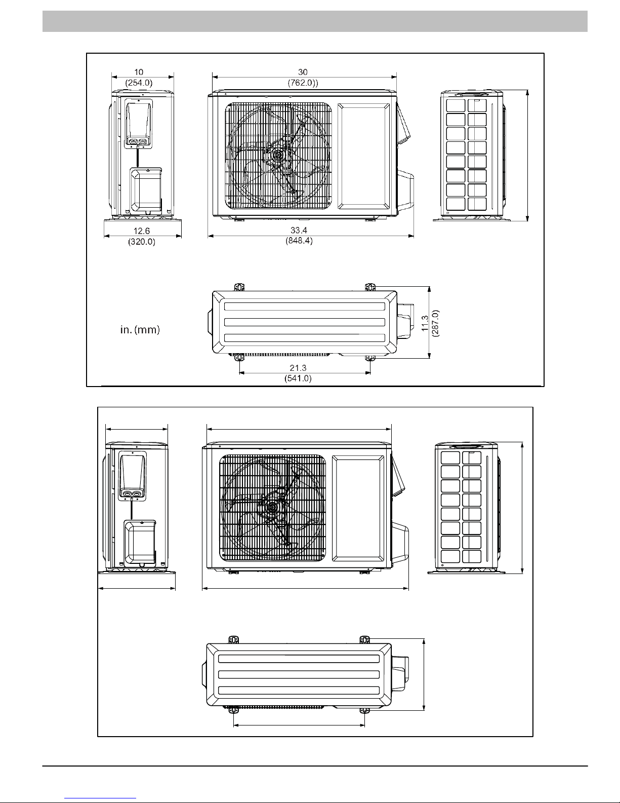
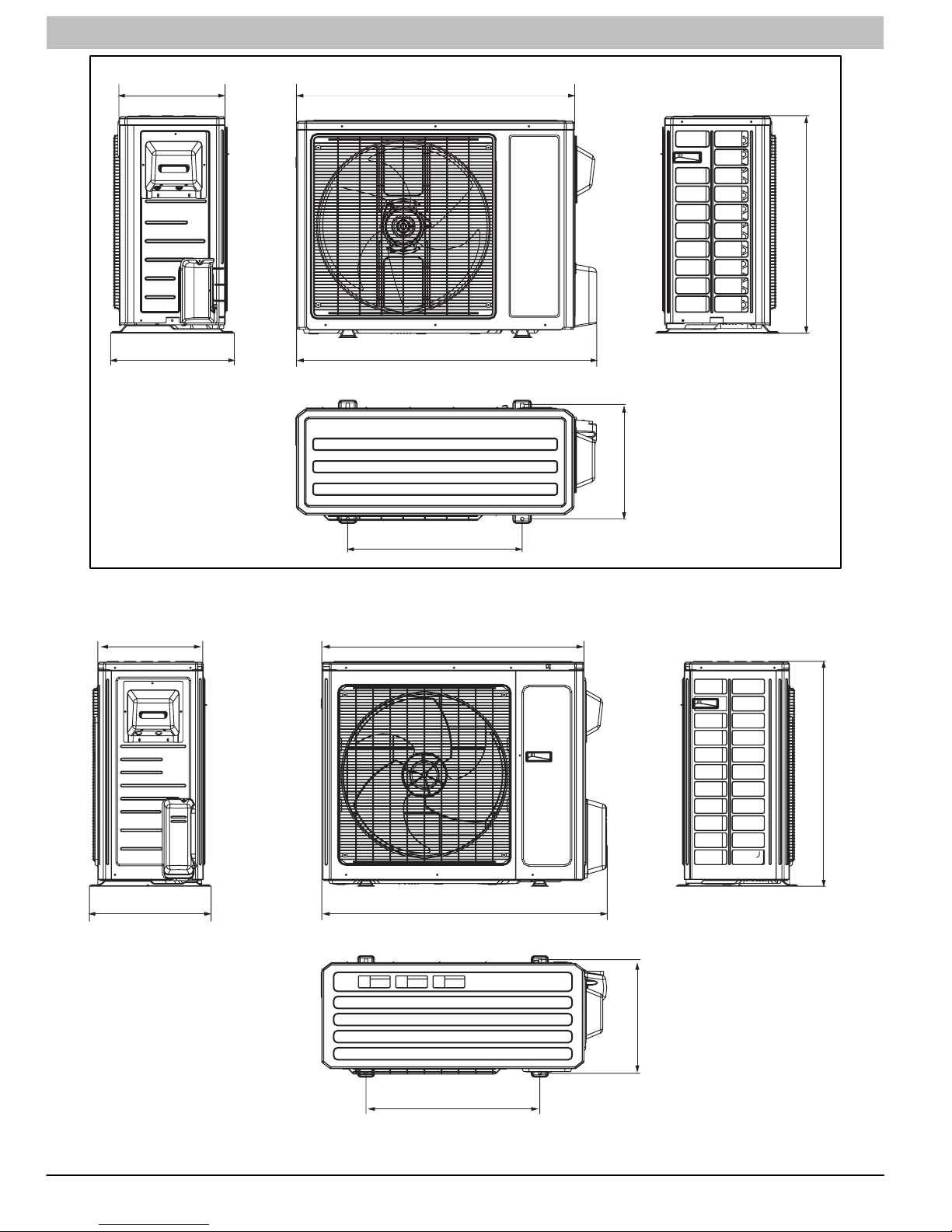
DIMENSIONS − OUTDOOR
UNIT SIZE − 09
(Net Operating Weight: 96 lbs.- 44 kg.)
21.3
(541)
10
(254.0)
12.6
(320.0)
in. (mm)
UNIT SIZE − 12
(Net Operating Weight: 107 lbs.- 49 kg.)
30
(762.0))
33.4
(848.4)
11.3
(287.0)
23.2
A12380
(589.3)
421 08 9204 00 19
21.3
(541.0)
A12381
Page 20
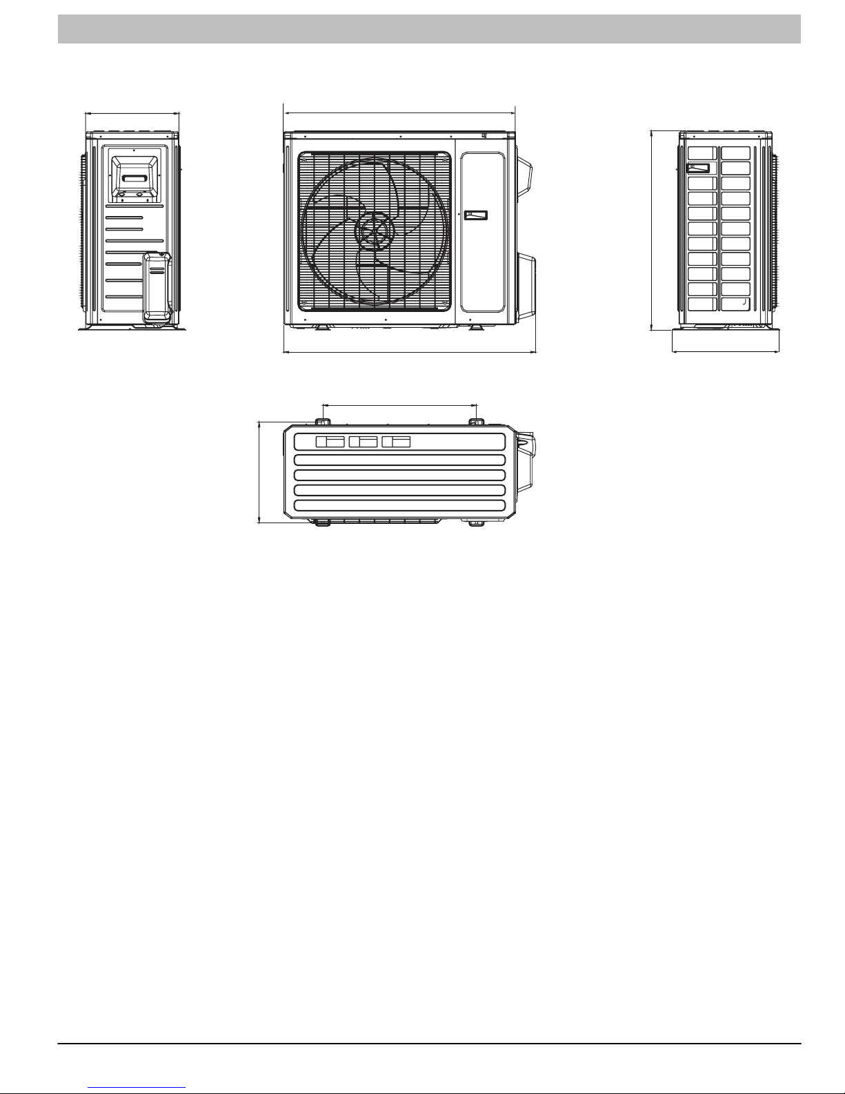
SERVICE MANUAL R−410A Ductless Split System: DLF4(A/H), DLC4(A/H)
13.4
(340.4)
15.6
(396.2)
in. (mm)
UNIT SIZE − 18
35
(889.0)
37.6
(955.0)
(Net Operating Weight: 99 lbs.- 45 kg.)
14.5
(368.3)
27.6
(701.0)
14.6
(368.3)
16.8
(426.7)
22
(558.8)
UNIT SIZE − 24
(914.4)
(980.4)
(Net Operating Weight: 121 lbs.- 55 kg.)
36
38.6
31.1
A12382
(789.9)
in. (mm)
20 421 08 9204 00
24
(609.6)
15.7
(398.8)
A12383
Page 21
SERVICE MANUAL R−410A Ductless Split System: DLF4(A/H), DLC4(A/H)
UNIT SIZE − 30 (Net Operating Weight: 154 lbs − 70 kg.)
36 (Net Operating Weight: 161 lbs − 73 kg.)
14.6
(370.8)
36
(914.4)
(789.9)
31.1
in. (mm)
(398.8)
15.7
38.6
(980.4)
24
(609.6)
16.7
(424.2)
A12379
421 08 9204 00 21
Page 22
SERVICE MANUAL R−410A Ductless Split System: DLF4(A/H), DLC4(A/H)
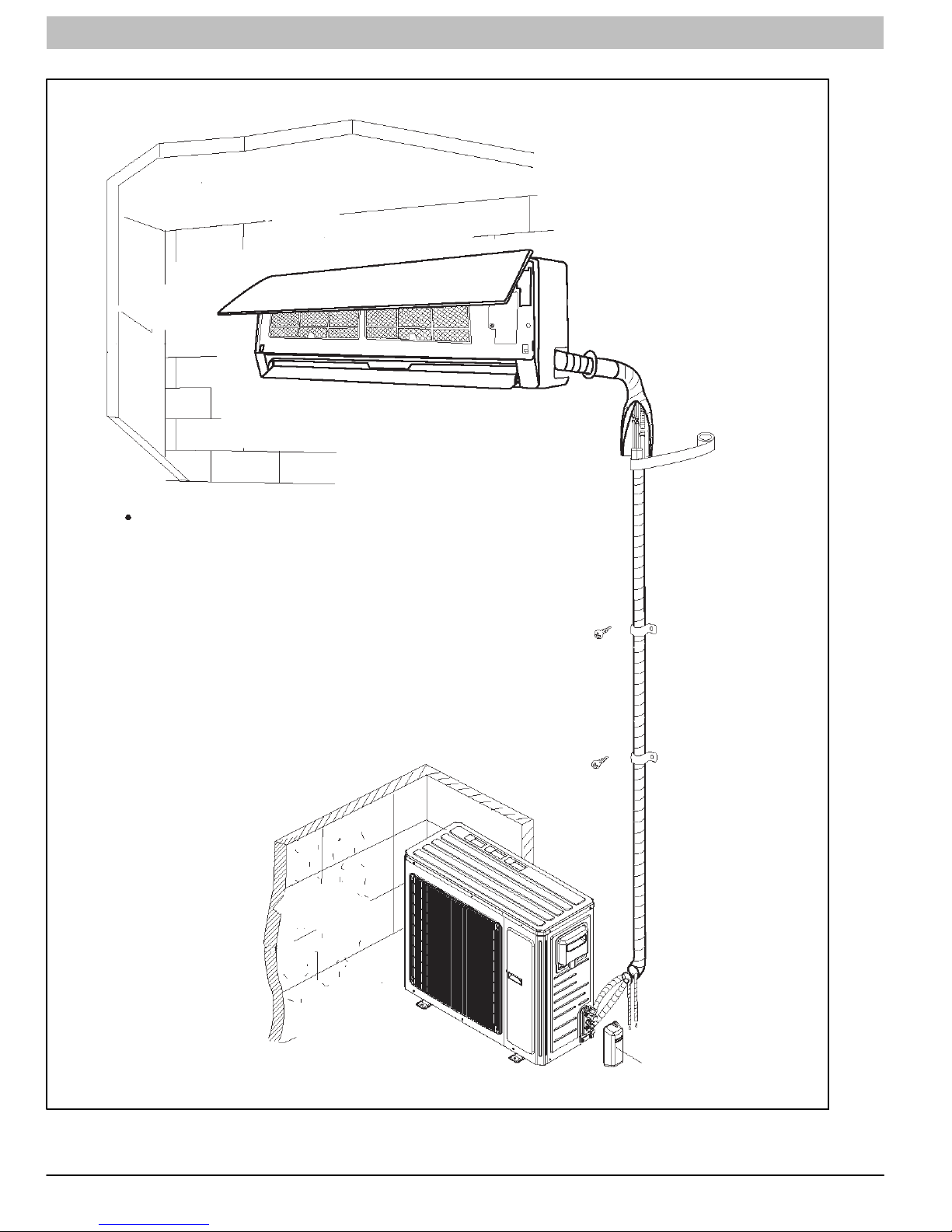
CLEARANCES
Indoor Unit
Distance to Ceiling
6” (152 mm)
Distance to Wall
6” (152 mm)
Clearance in front of unit
118” (2997 mm)
The clearance dimensions are necessary for a correct installation,
and are the minimum permissible distances to adjacent structures.
Distance to Floor
66” (1676 mm)
Distance to Wall
6” (152 mm)
NOTE: Refrigerant lines
may be routed in any of
the (4) directions, right,
right rear, left, or left rear.
See instructions for de
tails.
Outdoor Unit
Above Unit
20” (508 mm)
Distance to
Back Wall
12” (305 mm)
Air Discharge Side
79” (2007 mm)
Figure 2 - Unit clearance
Air Inlet Side
12” (305 mm)
Distance to Wall
20” (508 mm)
Valve Cover
A07891
22 421 08 9204 00
Page 23
SERVICE MANUAL R−410A Ductless Split System: DLF4(A/H), DLC4(A/H)
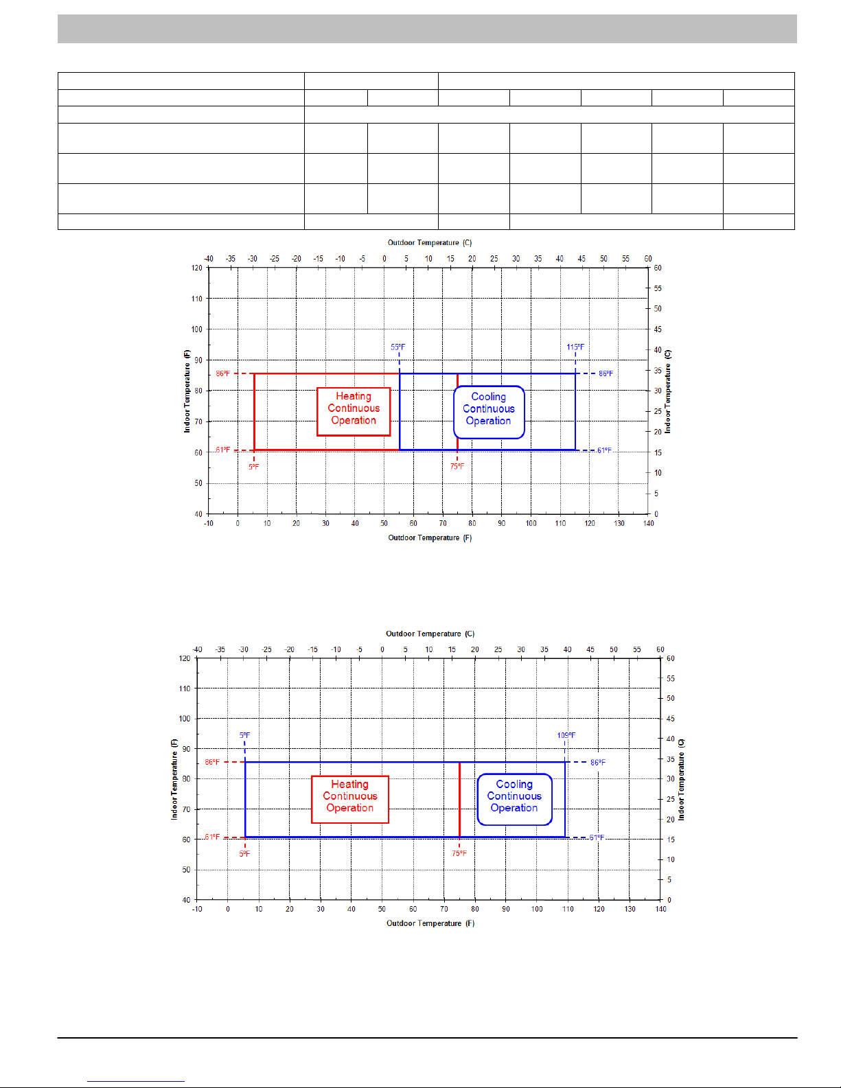
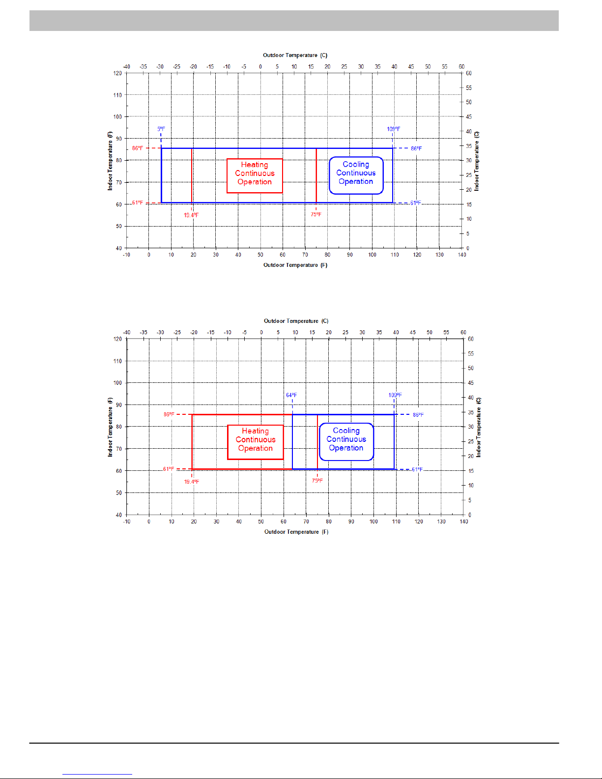
SYSTEM OPERATING ENVELOPES
Supply Voltage 115-1-60 AC 208/230-1-60 AC
Model Size 9k 12k 12k 18k 24k 30k 36k
Indoor Operating Range (A/C and HP) °F (°C) 61 - 86 (16 - 30)
Cooling Ambient Operating Range (A/C) °F (°C)
Cooling Ambient Operating Range (HP) °F (°C)
Heating Ambient Operating Range (HP) °F (°C)
Figure 3 4 5 6
55 - 115
(13 - 46)
55 - 115
(13 - 46)
5 - 75
(-15 - 24)
55 - 115
(13 - 46)
55 - 115
(13 - 46)
5 - 75
(-15 - 24)
5 - 109
(-15 - 43)
5 - 109
(-15 - 43)
5 - 75
(-15 - 24)
5 - 109
(-15 - 43)
5 - 109
(-15 - 43)
19.4 - 75
(-7 - 24)
5 - 109
(-15 - 43)
5 - 109
(-15 - 43)
19.4 - 75
(-7 - 24)
N/A 64 - 109
5 - 109
(-15 - 43)
19.4 - 75
(-7 - 24)
(18 - 43)
64 - 109
(18 - 43)
19.4 - 75
(-7 - 24)
Figure 3 - 9k / 12k 115V System Operating Envelopes
Figure 4 - 12k 230V System Operating Envelopes
421 08 9204 00 23
Page 24
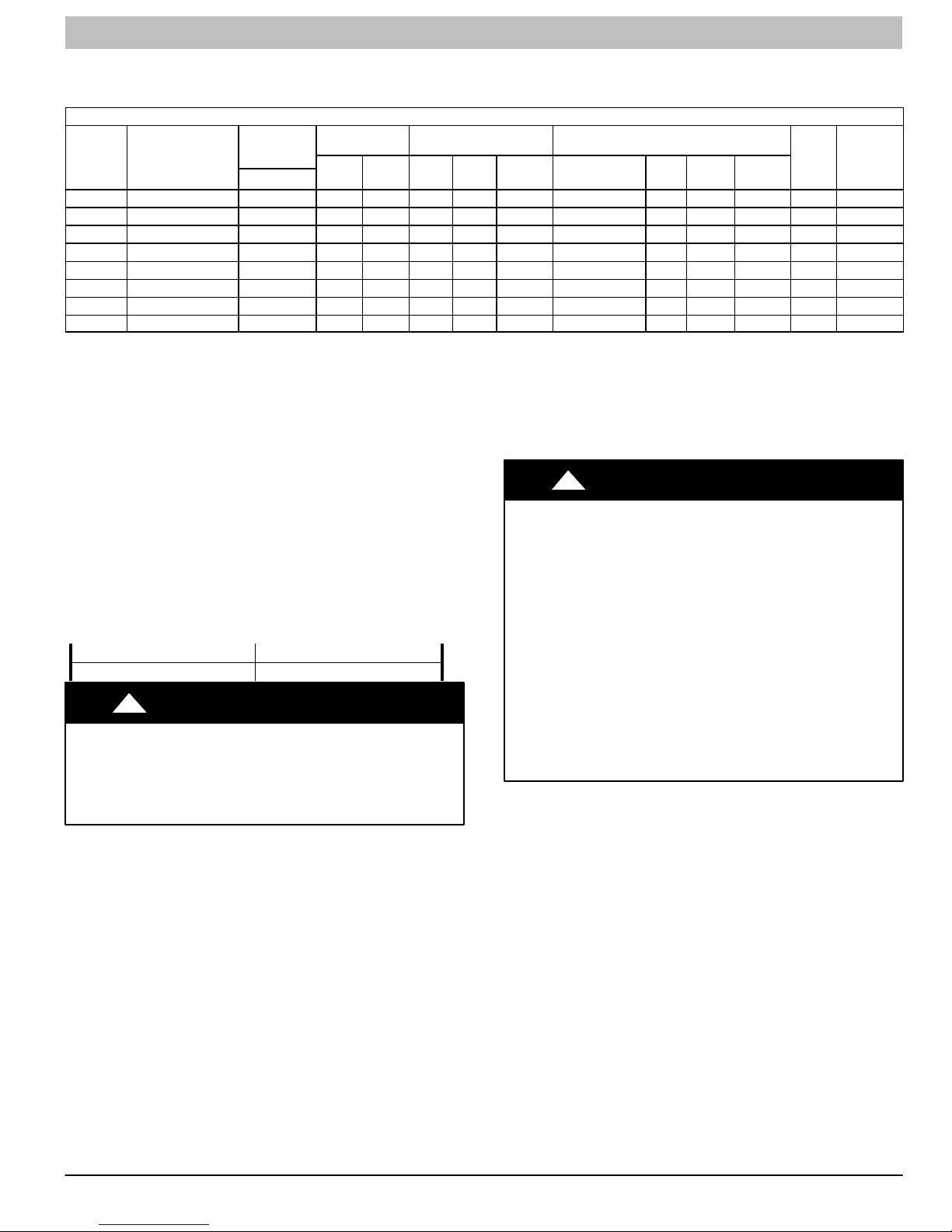
SERVICE MANUAL R−410A Ductless Split System: DLF4(A/H), DLC4(A/H)
SYSTEM OPERATING ENVELOPES (CONT.)
Figure 5 - 18k, 24k, and 30k 230V System Operating Envelopes
Figure 6 - 36k 230V System Operating Envelopes
24 421 08 9204 00
Page 25
SERVICE MANUAL R−410A Ductless Split System: DLF4(A/H), DLC4(A/H)
ELECTRICAL DATA
Table 2 − Accessory Condensate Pump Kit Contents
Electrical Data Table
Operating
Unit
Size
9K 115 −1−60 103/127 16.03 33 0.17 0.054 30 115 V−AC 0.38 0.056 20 22 35
12K 115−1−60 103/127 17.53 33 0.17 0.058 30 115 V−AC 0.38 0.056 20 23 40
12K 208/230−1−60 187/253 6.47 13.8 0.14 0.058 30 208/230 V−AC 0.20 0.056 20 10 15
18K 208/230−1−60 187/253 9.70 13.8 0.32 0.156 60 208/230 V−AC 0.28 0.075 20 13 20
24K 208/230−1−60 187/253 11.04 18.5 1.10 0.224 90 176−375V−DC 0.24 0.068 60 16 25
30K 208/230−1−60 187/253 13.45 40 0.45 0.228 100 208/230 V−AC 0.40 0.106 40 20 30
36K−AC 208/230−1−60 187/253 16.92 67 0.73 0.268 170 208/230 V−AC 0.47 0.114 60 24 35
36K−HP 208/230−1−60 187/253 17.50 67 0.73 0.268 170 208/230 V−AC 0.47 0.114 60 24 40
LEGEND
FLA − Full Load Amps
LRA − Locked Rotor Amps
MCA − Minimum Circuit Amps
RLA − Rated Load Amps
MOCP − Maximum Over Current Protection
WIRING
The main power is supplied to the outdoor unit. The field
supplied connecting cable from the outdoor unit to indoor unit
consists of four wires and provides the power for the indoor unit
as well as the communication signal and ground between the
outdoor and indoor unit.
Two wires are high voltage AC power, one is low voltage DC
signal and one is a ground wire.
Consult local building codes, NEC (National Electrical Code) or
CEC (Canadian Electrical Code) for special requirements.
Voltage drop on the connecting cable should be kept to a
minimum. Use cable size and max length below:
EQUIPMENT DAMAGE HAZARD
Failure to follow this caution may result in equipment
damage or improper operation.
Use copper conductors only with a minimum 300 volt
rating and 2/64 inch thick insulation.
System Voltage
Volts−Ph.−Freq.
18 AWG 50 ft. (16m)
16 AWG 100 ft. (33m)
!
CAUTION
Voltage
(Min/Max)
Compressor Outdoor Fan Indoor Fan
Output
RLA LRA FLA HP
Watts Volts FLA HP
!
EQUIPMENT DAMAGE HAZARD
Failure to follow this caution may result in equipment
damage or improper operation.
Be sure to comply with local codes while running wire from
indoor unit to outdoor unit.
Every wire must be connected firmly. Loose wiring may
cause terminal to overheat or result in unit malfunction. A
fire hazard may also exist. Therefore, be sure all wiring is
tightly connected.
No wire should be allowed to touch refrigerant tubing,
compressor or any moving parts.
Disconnecting means must be provided and shall be
located within sight and readily accessible from the air
conditioner.
Connecting cable with conduit shall be routed through
hole in the conduit panel.
CAUTION
Output
Watts
MCA
Fuse/CB
Amps
(MOCP)
Max
421 08 9204 00 25
Page 26
SERVICE MANUAL R−410A Ductless Split System: DLF4(A/H), DLC4(A/H)
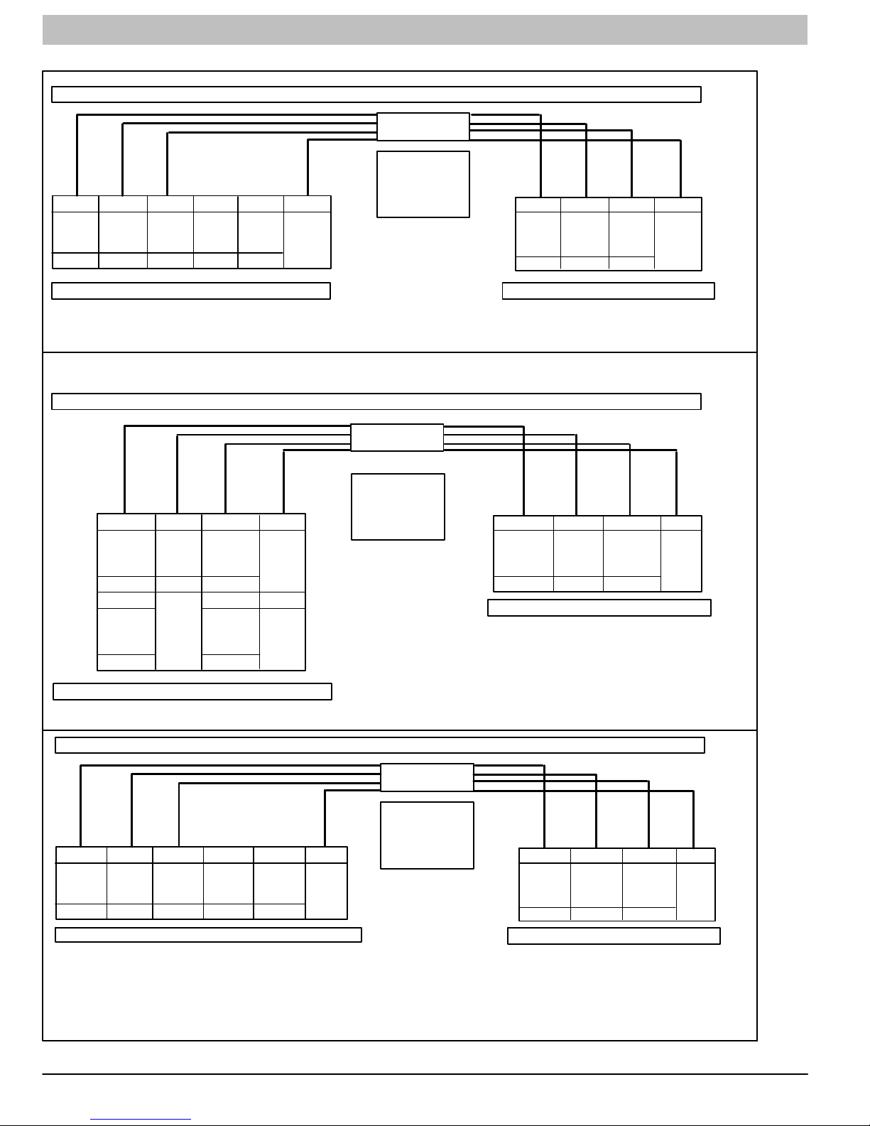
CONNECTION DIAGRAMS
DLC4/DLF4 9K − 12K, 115−1−60 Connection Diagram
Connecting Cable
Outdoor to Indoor
Use Copper
Conductors Only
With Minimum 300
N S L L N GND
Indoor
Unit
Control to
Indoor
Unit
Power to
115 −1−60 Low V DC
Power to
Indoor
Unit
115 −1−60 115−1−60 115−1−60
Main
Power
Supply
Main
Power
Supply
Ground
Volt, 2/64” Thick
Insulation
DLC4 9K − 12K Outdoor Unit Terminal Block DLF4 9K − 12K Indoor Unit Terminal Block
DLC4/DLF4 12K, 208/230−1−60 Connection Diagram
Connecting Cable
Outdoor to Indoor
N S L GND
Power
Outdoor
115 −1−60 Low V DC 115−1−60
from
Unit
Control
from
Outdoor
Unit
Power
from
Outdoor
Unit
Ground
SL2 GND
Power to
Indoor
208/230−1−60 Low V DC 208/230−1−60
Unit
Control to
Indoor
Unit
L2
Main Power
Supply
208/230−1−60 208/230−1−60
L1
Power to
Indoor
Unit
L1
Main Power
Supply
Ground
GND
DLC4 9K − 12K Outdoor Unit Terminal Block
DLC4/DLF4 18K − 36K, 208/230−1−60 Connection Diagram
L2 S L1 L2 GND
Power to
Indoor
208/230−1−60 Low V DC 208/230−1−60 208/230−1−60 208/230−1−60
Unit
Control to
Indoor
Unit
Power to
Indoor
Unit
DLC4 18K − 36K Outdoor Unit Terminal Block DLF4 18K − 36K Indoor Unit Terminal Block
L1
Main
Power
Supply
Main
Power
Supply
Ground
Use Copper
Conductors Only
With Minimum 300
Volt, 2/64” Thick
Insulation
Connecting Cable
Outdoor to Indoor
Use Copper
Conductors Only
With Minimum 300
Volt, 2/64” Thick
Insulation
SL2 GNDL1
Power
from
Outdoor
Unit
208/230−1−60 Low V DC 208/230−1−60
Control
from
Outdoor
Unit
Power
from
Outdoor
Unit
DLF4 12K Indoor Unit Terminal Block
L2 S L1 GND
Power to
Indoor
Unit
208/230−1−60 Low V DC 208/230−1−60
Control to
Indoor
Unit
Power to
Indoor
Unit
Ground
Ground
26 421 08 9204 00
Figure 7 - Connection Diagrams
Page 27

SERVICE MANUAL R−410A Ductless Split System: DLF4(A/H), DLC4(A/H)
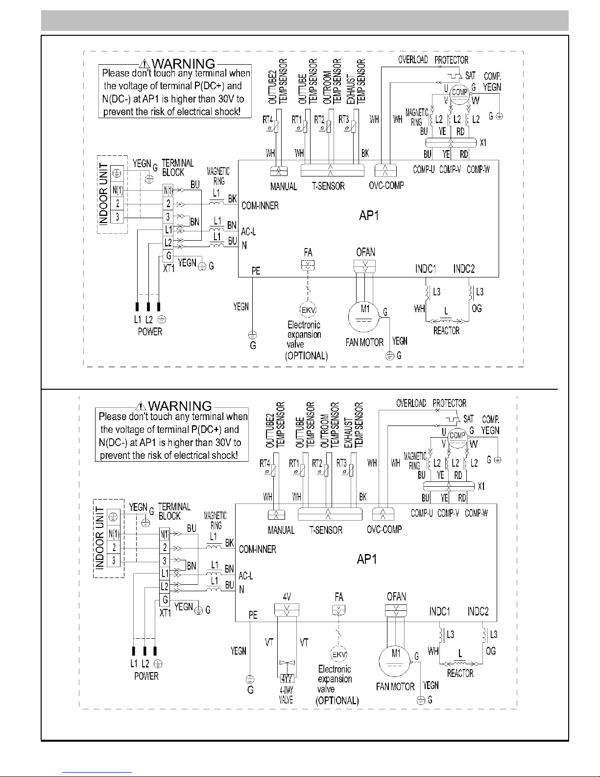
WIRING DIAGRAMS (CONT.)
Symbol Color Symbol Symbol Parts Name
OG Orange Protective Earth
WH White COMP Compressor
YE Yellow CT1,2 Overload
RD Red 4V 4−Way Valve
YEGN Yellow Green XT Terminal Block
BN Brown
BU Blue
BK Black
Size 9k and 12k, 115V, Indoor Unit
421 08 9204 00 27
Page 28

SERVICE MANUAL R−410A Ductless Split System: DLF4(A/H), DLC4(A/H)
WIRING DIAGRAMS (CONT.)
Size 9k and 12k, 115V, AC Outdoor Unit
Size 9k and 12k, 115V, HP Outdoor Unit
28 421 08 9204 00
Page 29

SERVICE MANUAL R−410A Ductless Split System: DLF4(A/H), DLC4(A/H)
WIRING DIAGRAMS (CONT.)
Size 12k and 18k, 230V, Indoor Unit
421 08 9204 00 29
Page 30

SERVICE MANUAL R−410A Ductless Split System: DLF4(A/H), DLC4(A/H)
WIRING DIAGRAMS (CONT.)
Size 24k, 230V, Indoor Unit
30 421 08 9204 00
Size 12k, 230V, Outdoor Unit
Page 31
SERVICE MANUAL R−410A Ductless Split System: DLF4(A/H), DLC4(A/H)
WIRING DIAGRAMS (CONT.)
Size 18k, 230V, AC, Outdoor Unit
421 08 9204 00 31
Size 18k, 230V, HP, Outdoor Unit
Page 32

SERVICE MANUAL R−410A Ductless Split System: DLF4(A/H), DLC4(A/H)
WIRING DIAGRAMS (CONT.)
Size 24k, 230V, AC, Outdoor Unit
32 421 08 9204 00
Size 24k, 230V, HP, Outdoor Unit
Page 33

SERVICE MANUAL R−410A Ductless Split System: DLF4(A/H), DLC4(A/H)
WIRING DIAGRAMS (CONT.)
421 08 9204 00 33
Size 30k & 36k, 230V, AC & HP, Indoor Unit
Page 34

SERVICE MANUAL R−410A Ductless Split System: DLF4(A/H), DLC4(A/H)
WIRING DIAGRAMS (CONT.)
Size30k, 230V, HP, Outdoor Unit
34 421 08 9204 00
Size 36k, 230V, AC, Outdoor Unit
Page 35

SERVICE MANUAL R−410A Ductless Split System: DLF4(A/H), DLC4(A/H)
WIRING DIAGRAMS (CONT.)
Size36k, 230V, HP, Outdoor Unit
421 08 9204 00 35
Page 36

SERVICE MANUAL R−410A Ductless Split System: DLF4(A/H), DLC4(A/H)
REFRIGERANT SYSTEM DIAGRAM
Cooling Only Models Size 9k, 12k, 115V and Size 12k 18k, 24k 230 V
Cooling and Heating Models Size 12k, 115V and Size 12k 18k, 24k 230 V
36 421 01 9204 00
Figure 8 - Refrigerant System Diagrams
Page 37

SERVICE MANUAL R−410A Ductless Split System: DLF4(A/H), DLC4(A/H)
REFRIGERANT SYSTEM DIAGRAM
Cooling Only Models Size 36k 230 V
Cooling and Heating Models Size 30k, 36k 230 V
Refrigerant pipe diameter
Liquid: ¼”
Gas: ⅝”
421 08 9204 00 37
Figure 9 - Refrigerant System Diagrams
Page 38

SERVICE MANUAL R−410A Ductless Split System: DLF4(A/H), DLC4(A/H)
REFRIGERANT LINES
Refrigerant Line Routing
The refrigerant lines may be routed in any of the four directions
shown in Figure 4.
For maximum serviceability, it is recommended to have
refrigerant line flare connections and the drain connection on the
outside of the wall that the fan coil is mounted on.
Unit Size Hole Diameter, In. (mm)
9K, 12K, 18K 2.2 (56)
24K, 30K, 36K 2.8 (71)
If piping is going through the right or left side:
Use a small saw blade to carefully remove the corresponding
plastic covering on side panel and drill the appropriate size hole
where the pipe is going through the wall. See table above.
Hole SIZES
Remove knockout 1 to run just the wiring. Remove knockout 1
As Viewed From Front
and 2 or knockout 1, 2, and 3 if running both piping and wiring
through the side of the unit. See Figure 11.
NOTE: If required, a condensate pump is available for the
1 Right Exit
2 Right Rear Exit
(a)
(b)
3 Left Exit
4 Left Rear
Exit
A08281
Figure 10 - Refrigerant Line Routing
Determine pipe hole position using the mounting plate as a template. Drill pipe hole diameter per chart below. The outside pipe
hole is ½ in. (13mm) min. Lower than inside pipe hole, so it
slants slightly downward. See figure 5.
application.
General Guidelines
The units are shipped with full charge of R−410A refrigerant. All
charges, line sizing, and capacitiies are based on runs of 25ft.
(7.6m). For runs over 25ft. (7.6m) consult long line section for
charge adjustments.
Refrigerant lines should not be buried in the ground. If it is necessary to bury the lines, not more than 36 inches (914mm)
should be buried. Provide a minimum of 6 inch (152mm) vertical
rise to service valves to prevent refrigerant migration.
Both lines must be insulated. Use a minimum of ½ inch
(12.7mm) thick insulation. Closed−cell insulation is recommen-
1/2 in. (13 mm)
Min.
ded in al long−line applications.
Special consideration should be given to isolating interconnect-
ing tubing from the building structure. Isolate the tubing so that
vibration or noise is not transmitted into the structure.
INDOOR
OUTDOOR
A07371
Figure 11 - Drill Holes
Long Line Applications
No change in line sizing is required.
Add refrigeration per table below.
R−410A Refrigerant Charge Table
Charge Amount *
LBS (kg)
Unit Size
9K 2.64 (1.20) 2.64 (1.20) 0.16 (15) 0.22 (20) EXV EXV
12K 2.86 (1.30) 2.86 (1.30) 0.16 (15) 0.22 (20) EXV EXV
18K 3.09 (1.40) 3.09 (1.40) 0.16 (15) 0.22 (20) EXV EXV
24K 3.53 (1.60) 3.53 (1.60) 0.16 (15) 0.54 (50) EXV EXV
30K −−−− 5.29 (2.40) −−−− 0.54 (50) −−−− EXV
36K 5.30 (2.40) 5.73 (2.60) 0.54 (50) 0.54 (50) CAP EXV
* Charge is for piping that runs up to 25 ft. (7.6 m)
** For piping runs greater than 25 ft. (7.6 m), add this amount of charge per foot of extra piping, up to the allowable length, specified in the above table.
*** EXV − Electronic Expansion Device
Cool Only Heat Pump Cool Only Heat Pump Cool Only Heat PumpHeat Pump
Additional Charge Amount **
oz/ft (g/m)
Metering Device ***
REFRIGERANT LINE LENGTHS ft. (m)
Max Line
Unit Size
9K 50 (15) 33 (10) 33 (10)
12K 66 (20) 33 (10) 33 (10)
18, 24K 82 (25) 33 (10) 33 (10)
30, 36K 98 (30) 33 (10) 33 (10)
Length
Max Elevation
(ID over OD)
38 421 08 9204 00
Max Elevation
(OD over ID)
Page 39

SERVICE MANUAL R−410A Ductless Split System: DLF4(A/H), DLC4(A/H)
t
Deep Vacuum Method
!
UNIT DAMAGE HAZARD
Failure to follow this caution may result in equipment
damage or improper operation.
Never use the system compressor as a vacuum pump.
Refrigerant tubes and indoor coil should be evacuated using the
recommended deep vacuum method of 500 microns. The
alternate triple evacuation method may be used if the procedure
outlined below is followed. Always break a vacuum with dry
nitrogen.
SYSTEM VACUUM AND CHARGE
Using Vacuum Pump
Completely tighten flare nuts A, B, C, D, connect manifold gage
charge hose to a charge port of the low side service valve.
(See Fig. 13.)
Connect charge hose to vacuum pump.
Fully open the low side of manifold gage. (See Fig. 14)
Start vacuum pump
Evacuate using either deep vacuum or triple evacuation method.
After evacuation is complete, fully close the low side of manifold
gage and stop operation of vacuum pump.
The factory charge contained in the outdoor unit is good for up to
25 ft. (8 m) of line length. For refrigerant lines longer than 25 ft
(8 m), add 0.1 oz. per foot of extra piping up to the maximum
allowable length.
Disconnect charge hose from charge connection of the low side
service valve.
Fully open service valves B and A.
Securely tighten caps of service valves.
Outdoor Unit
Service Valve
CAUTION
Refrigerant
Low Side
A
High Side
B
Figure 12 - Service Valve
Indoor Uni
C
D
A07360
The deep vacuum method requires a vacuum pump capable of
pulling a vacuum of 500 microns and a vacuum gage capable of
accurately measuring this vacuum depth. The deep vacuum
method is the most positive way of assuring a system is free of
air and liquid water. (See Fig. 15)
5000
4500
4000
3500
3000
2500
2000
MICRONS
1500
1000
500
01234567
MINUTES
LEAK IN
SYSTEM
VACUUM TIGHT
TOO WET
TIGHT
DRY SYSTEM
Figure 14 - Deep Vacuum Graph
Triple Evacuation Method
The triple evacuation method should only be used when vacuum
pump is only capable of pumping down to 28 in. of mercury
vacuum and system does not contain any liquid water.
Refer to Fig. 16 and proceed as follows:
Pump system down to 28 in. of mercury and allow pump to continue operating for an additional 15 minutes.
Close service valves and shut off vacuum pump.
Connect a nitrogen cylinder and regulator to system and open
until system pressure is 2 psig.
Close service valve and allow system to stand for 1 hr. During
this time, dry nitrogen will be able to diffuse throughout the system absorbing moisture.
Repeat this procedure as indicated in Fig. 16. System will then
be free of any contaminants and water vapor.
EVACUATE
BREAK VACUUM WITH DRY NITROGEN
WAIT
A95424
Manifold Gage
500 microns
Low side valve
Charge hose
Low side valve
High side valve
Charge hose
Vacuum pump
Figure 13 - Manifold
421 08 9204 00 39
A07361
EVACUATE
BREAK VACUUM WITH DRY NITROGEN
WAIT
EVACUATE
CHECK FOR TIGHT, DRY SYSTEM
(IF IT HOLDS DEEP VACUUM)
RELEASE CHARGE INTO SYSTEM
A95425
Figure 15 - Triple Evacuation Method
Final Tubing Check
IMPORTANT: Check to be certain factory tubing on both indoor
and outdoor unit has not shifted during shipment. Ensure tubes
are not rubbing against each other or any sheet metal. Pay close
attention to feeder tubes, making sure wire ties on feeder tubes
are secure and tight.
Page 40

SERVICE MANUAL R−410A Ductless Split System: DLF4(A/H), DLC4(A/H)
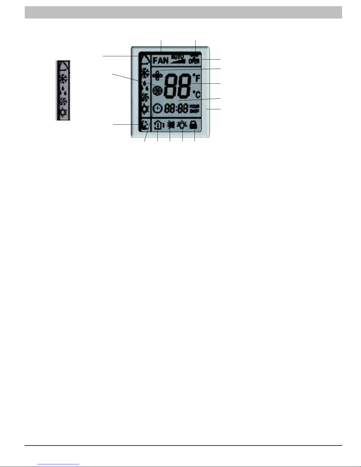
Remote Control and Functions
Remote Control, Size 09-24
1. Remote Control Display
2. ON/OFF Button
1
3. MODE Button
4. Setpoint Clock, Timer Up (+) and Down (-) Buttons
5. Fan Speed
6. Horizontal Louver Swing Button
7. Clock Button
23
4
5
7
9
10
12
8. Timer ON Button
9. Dry Coil Button
10. Temperature Button
11. Timer OFF Button
6
12. Turbo Mode Button
8
13. Sleep Mode button
14. Light Button to Turn ON or OFF Display on Front Panel
11
14
13
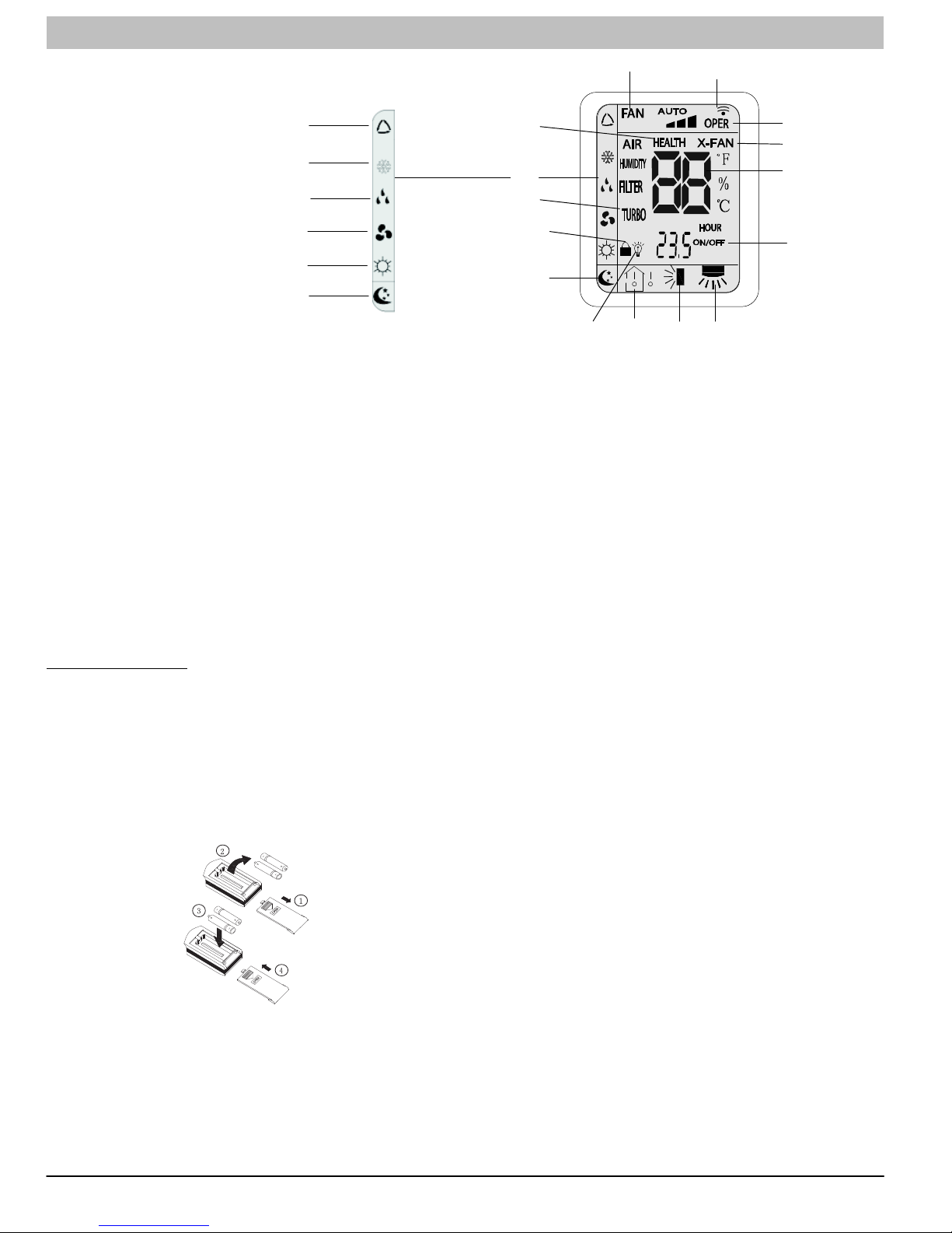
1. Remote Control Display
2. ON/OFF Button
3. MODE Button
1
4. Setpoint, Timer Up (+) and Down (-) Buttons
5. Fan Speed
6. Horizontal Louver Swing Button
7. Left/Right Louver Swing Button (Not available with these models)
8. HEALTH/SAVE Button (Not available with these models)
2
4
5
8
9
3
9. Dry Coil Button
10. Temperature Button (Not available with these models)
11. Timer Button
12. Turbo Mode Button (Not available with these models)
13. Sleep Mode button
6
14. Light Button to Turn ON or OFF Display on Front Panel
7
10
11
A12434
Remote Control, Size 30-36
12
13
40 421 08 9204 00
14
A12390
Page 41
SERVICE MANUAL R−410A Ductless Split System: DLF4(A/H), DLC4(A/H)
Remote Control Display, Size 09−24
3
MODE DISPLAY
AUTO
COOL
DRY
FAN
HEAT
NOTE: Symbols shown in this manual are for the purpose of demonstration. During actual operation, only the relevant
symbols are displayed.
TRANSMISSION INDICATOR: Illuminates when remote control
transmits signals to the indoor unit.
This symbol appears when the unit is turned on by the remote con-
trol, and disappears when the unit is turned off.
FAN SPEED DISPLAY: Indicates the set fan speed. AUTO is dis-
played when unit is running in AUTO mode.
MODE DISPLAY: Indicates the current operation mode “AUTO”,
“COOL”, “DRY”, “FAN ONLY”, or “HEAT”
SLEEP DISPLAY: Indicates unit is running in SLEEP mode.
TEMPERATURE DISPLAY: Temperature setting from 61F (16C)
to 86F (30C) will be displayed. If FAN mode is selected,
there will be no temperature displayed.
CLOCK DISPLAY: Indicates the current time (0 to 24 hours).
CLOCK INDICATOR: Displayed with time and is not displayed
when setting ON/OFF timer.
4
10
5
1
2
11
6
7
9
A12391
151413128
TIMER ON / TIMER OFF DISPLAY: ON is displayed if TIMER ON
is set. OFF is displayed if TIMER OFF is set. ON OFF
displayed if both ON and OFF timers are set.
TURBO DISPLAY: Indicates unit is running in Turbo Mode.
DRY COIL DISPLAY: Indicates unit is running in DRY COIL mode
where the fan continues to run after the unit is shut off to
dry the coil.
TEMPERATURE DISPLAY: Indicates if room temperature or set
point temperature is being displayed on the front panel.
SWING DISPLAY: Sets louver position or set louvers to continu-
ously move for better air distribution.
LIGHT DISPLAY: Indicates if LED display on the front panel is illu-
minated.
LOCK DISPLAY: Indicates if remote control is locked.
421 08 9204 00 41
Page 42
SERVICE MANUAL R−410A Ductless Split System: DLF4(A/H), DLC4(A/H)
Remote Control Display, Size 30−36
MODE DISPLAY
AUTO
COOL
DRY
FAN
HEAT
SLEEP
NOTE: Symbols shown in this manual are for the purpose of demonstration. During actual operation, only the relevant
symbols are displayed.
TRANSMISSION INDICATOR: Illuminates when remote control
transmits signals to the indoor unit.
This symbol appears when the unit is turned on by the remote con-
trol, and disappears when the unit is turned off.
FAN SPEED DISPLAY: Indicates the set fan speed. AUTO is dis-
played when unit is running in AUTO mode.
MODE DISPLAY: Indicates the current operation mode “AUTO”,
“COOL”, “DRY”, “FAN ONLY”, or “HEAT”
SLEEP DISPLAY: Indicates unit is running in SLEEP mode.
TEMPERATURE DISPLAY: Temperature setting from 61F (16C)
to 86F (30C) will be displayed. If FAN mode is selected,
there will be no temperature displayed.
Battery Installation
Two AAA 1.5 v alkaline batteries (included) are required for
operation of the remote control.
To install or replace batteries :
Slide the back cover off the control to open the battery
compartment.
Remove old batteries if you are replacing the batteries.
Insert batteries. Follow the polarity markings inside the battery
compartment.
Replace battery compartment cover.
3
8
4
10
15
5
14 1312
Left/Right Louver Swing: Not available on these models.
Health/Save: Not available on these models.
SETTING ON / OFF TIMES: 0.5 to 24 hours.
TURBO DISPLAY: Not available on these models.
DRY COIL DISPLAY: Indicates unit is running in DRY COIL mode
where the fan continues to run after the unit is shut off to
dry the coil.
TEMPERATURE DISPLAY: Not available on these models.
SWING DISPLAY: Sets louver position or set louvers to continu-
ously move for better air distribution.
LIGHT DISPLAY: Indicates if LED display on the front panel is illu-
minated.
LOCK DISPLAY: Indicates if remote control is locked.
NOTE:
1. When replacing batteries, do not use old batteries or a
different type battery. This may cause the remote control
to malfunction.
2.If the remote is not going to be used for several weeks,
remove the batteries. Otherwise battery leakage may
damage the remote control.
3. The average battery life under normal use is about 6
months.
4. Replace the batteries when there is no audible beep from
the indoor unit or if the Transmission Indicator fails to light.
1
2
11
6
9
7
42 421 08 9204 00
A08299
Page 43
SERVICE MANUAL R−410A Ductless Split System: DLF4(A/H), DLC4(A/H)
Function and Controls
Description of Each Control Operation
Temperature Parameters
Indoor preset temperature (T
Indoor ambient temperature (T
preset)
amb.)
Basic Functions
Once energized, in no case should the compressor be restarted
within less than 3 minutes. In the situation that memory function
is available, for the first energization, if the compressor is at stop
before de−energization, the compressor will be started without a
3−minute lag; if the compressor is in operation before
de−energization, the compressor will be started with a 3−minute
lag; and once started, the compressor will not be stopped within
6 minutes regardless of changes in room temperature;
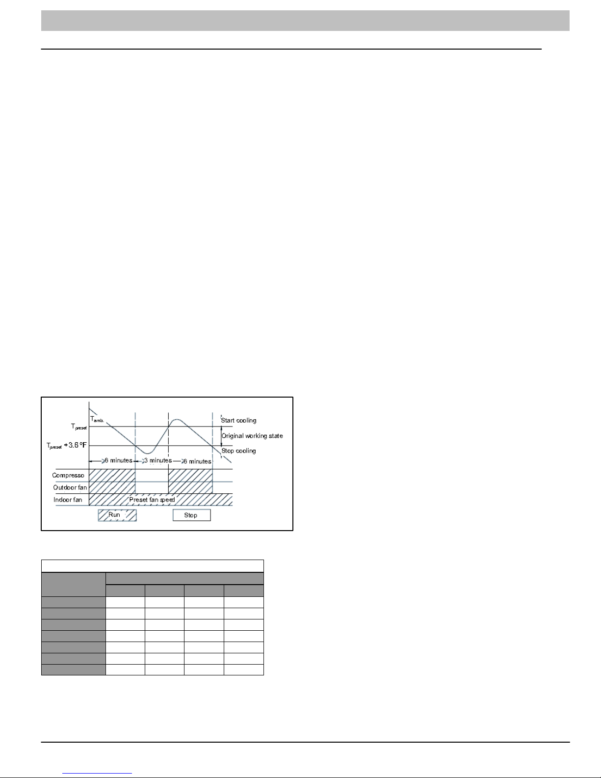
Cooling Mode
Working Conditions and Cooling Process.
When T
amb ≥ Tpreset, the unit will enter cooling operation, in which
case the indoor fan, the outdoor fan and the compressor will work
and the indoor fan will run at preset speed.
When T
amb Tpreset −3.6°F , the compressor will stop, the out-
door fan will stop with a time lag of 60s, and the indoor fan will run
at preset speed.
When T
preset −3.6°F < Tamb. < Tpreset +1.8°F, the unit will remain at
its previous state.
Under this mode, the four−way valve will be de−energized and tem-
perature can be set within a range from 61°F to 86°F. If the com-
pressor is shut down for some reason, the indoor fan and the swing
device will operate at original state.
PROTECTION
Antifreeze Protection
Under cooling and dehumidifying mode, 6 minutes after the
compressor is started:
evap 35.6°F, the compressor will operate at reduced
If T
frequency.
evap 30.2°F is detected for duration of 3 minutes, the
If T
compressor will stop, and after 60 seconds, the outdoor fan will
stop; and under cooling mode, the indoor fan and the swing
motor will remain at the original state.
If Tevap. 42.8°F and the compressor has remained at OFF for at
least 3 minutes, the compressor will resume its original
operation state.
Total current up and frequency down protection
total A, frequency rise will be allowed; if Itotal ≥ B, frequency
If I
rise will not be allowed; if I
reduced frequency; and if I
total ≥ C, the compressor will run at
total ≥ D, the compressor will stop and
the outdoor fan will stop with a time lag of 30s. Lag will be 60s for
size 30 and 36 units.
Dehumidifying Mode
Working Conditions and Dehumidifying Process
amb>Tpreset, the unit will enter cooling and dehumidifying
If T
mode, in which case the compressor and the outdoor fan will
operate and the indoor fan will run at low speed.
If Tpreset −3.6°F Tamb Tpreset, the compressor remains at
its original operation state.
If Tamb.< Tpreset −3.6°F, the compressor will stop, the outdoor fan
will stop with a time lag of 60s, and the indoor fan will
operate at low speed.
Protection
Protection is the same as that under the cooling mode.
Heating Mode
Working Conditions and Heating Process
amb. Tpreset +3.6°F , the unit enters heating mode, in which
If T
case the four−way valve, the compressor and the outdoor fan
will operate simultaneously, and the indoor fan will run at preset
speed in the condition of preset cold air prevention.
If Tamb. ≥ Tpreset +9°F , the compressor will stop, the outdoor fan
will stop with a time lag of 60s, and the indoor fan will stop after
60−second blow at low speed
preset +3.6°F < Tamb. < Tpreset +9°F , the unit will maintain its
If T
original operating status.
Under this mode, the four−way valve is energized and
temperature can be set within a range of 61°F − 86°F. The
operating symbol, the heating symbol and preset temperature
Figure 16 - Cooling Mode
are revealed on the display.
Defrost Mode
Total Current Table
Variables
Unit Size - V
A B C D
9k115V 10A 12A 14A 16A
12K115V 14A 16A 18A 20A
12K230V 6A 7A 8A 9A
18k230V 8A 9A 10A 11A
24K230V 10A 11A 12A 13A
30K230V 16A 17A 18A 20A
36K230V 16A 17A 18A 20A
Condition and Defrost Process
When T
if T
outdoor amb. ≥41°F and the compressor has run for 3 hour,
outdoor tube < 0°F is continuously detected for 1 minute, the
unit will enter defrost. [Note: the accumulated time is cleared if
one of the below condition is met. T
outdoor ambient > 41°F, the
compressor starts up after switching to cooling or dry mode,
when defrosting is finished; for other situations besides above
conditions, the accumulated time will not be cleared (including
the unit stops when reaching the temperature point, the unit
stops for protection, switching to fan mode, et. )]
When duration of successive heating operations is more than 45
minutes, or accumulated heating time IS more than 90 minutes,
and one of the following conditions is reached, the unit will enter
the defrost mode after 3 minutes.
a. Toutdoor amb. >41°F, Toutdoor tube 28.4°F;
b. 28.4°F Toutdoor amb. <41°F, Toutdoor tube 21.2°F;
c. 23°F Toutdoor amb. <28.4°FC, Toutdoor tube 17.6°F;
421 08 9204 00 43
Page 44

SERVICE MANUAL R−410A Ductless Split System: DLF4(A/H), DLC4(A/H)
d. 14°F Touter amb. <23°F, Touter tube − Tcompensatorys (Toutdoor
amb. −
5.4°F)
e. Toutdoor amb.>14°F Touter tube − Tcompensatorys (Toutdoor amb.
−
5.4°F)
temperature is 77°F; if T
stop, the outdoor fan will stop with a time lag of 1 minute, and the
indoor fan will run at preset speed. If T
Tpreset , the unit will remain in its original state.
amb.Tpreset −3.6°F, the compressor will
preset –(−3.6°F)< Tamb.<
Under AUTO mode, if Tamb. Tpreset +3.6°F is detected, the unit
After energization, for the first defrost, T
not the first defrost, T
compensation will be determined by Toutdoor
compensation =0 °F; if it is
pipe when defrost ends.
outdoor pipe >35.6°F; Tcompensation = 0°F;
a. T
b. Toutdoor pipe 35.6°F; Tcompensation = 5.4°F;
will select to run under heating mode, in which case the preset
temperature is 64.4°F; if Tamb.Tpreset +9°F, the compressor will
stop, the outdoor fan will stop with a time lag of 1 minute, and the
indoor fan will blow residual heat; and if T
preset +3.6°F < Tamb. <
Tpreset +9°F, the unit will remain in its original state. The
cooling−only unit will run under fan mode.
During defrosting, if operation time for compressor doesn’t reach
3 minutes, the condenser will not defrost in the next 2 hours. At
the time of defrost the compressor stops operation, and 30
seconds later, the outdoor fan stops operation. In an additional
30 seconds, the 4−way valve will stop operation. 30 seconds
later, compressor will increase it’s frequency to 85 Hz for
defrosting. Defrost will last for 450 seconds, or until the outdoor
pipe ≥ 50°F. When defrost is complete the compressor will
decrease its frequency. 30 seconds later the compressor will
stop operation. In 30 seconds the 4−way valve will be started up.
Under AUTO mode, if 68°F
its original state.
Protection
In cooling operation, protection is the same as that under the
cooling mode;
In heating operation, protection is the same as that under the
heating mode;
When ambient temperature changes, operation mode will be
converted preferentially. Once started, the compressor will
remain unchanged for at least 6 minutes.
< Tamb. < 77°F, the unit will remain in
60 seconds later the compressor and outdoor fan will operate.
(6) Common Protection Functions and Fault Display under
Protection
Cold air prevention
COOL, HEAT, DRY and AUTO Modes
The unit is started under heating mode (the compressor is ON):
In the case of T
indoor amb. <75.2°F : if Ttube 107.6°F and
the indoor fan is stopped, the indoor fan will begin to run at low
speed with a time lag of 2 minutes. Within 2 minutes, if Ttube
>104°F, the indoor fan also will run at low speed; and after
1−minute operation at low speed, the indoor fan will be ramped
to operation at a preset speed. Within 1−minute of low speed
operation or 2−minutes of non−operation, if T
tube>108°F, the fan
will run at preset speed.
In the case of Ti
ndoor amb. ≥ 75°F: if Ttube 108°F, the indoor
fan will run at low speed, and after one minute, the indoor fan will
be ramped to preset speed. Within one−minute low speed
operation, if T tube>107.6°F, the indoor fan will be ramped to
preset speed.
indoor amb. indicated in and refers to, the indoor
Note: T
ambient temperature before the command to start the
compressor is performed, or after the unit is withdrawn from
defrost and the defrost symbol is cleared.
Total current up and frequency down protection
If the total current Itotal ≤W, frequency rise will be allowed; if Itotal
≥X frequency rise will not be allowed; if Itotal ≥Y, the compressor
will run at reduced frequency; and if I
total ≥Z, the compressor will
stop and the outdoor fan will stop with a time lag of 30s.
Overload protection
T tube : measured temperature of outdoor heat exchanger under
cooling mode; and measured temperature of indoor heat
exchanger under heating mode.
1) Cooling overload
tube 125.6°F, the unit will return to its original operation
a. If T
state.
b. If
T tube 131°F, frequency rise is not allowed.
tube 136.4°F, the compressor will run at reduced
c. If T
frequency.
d. If T
tube 143.6°F, the compressor will stop and the indoor fan
will run at preset speed.
2) Heating overload
a. If T
tube125.6°F, the unit will return to its original operation
state.
b. If T
tube 131°F, frequency rise is not allowed.
c. If T tube w136.4°F, the compressor will run at reduced
frequency.
d. If
T tube 143.6°F, the compressor will stop and the indoor fan
will blow residual heat and then stop.
Exhaust temperature protection of compressor
If exhaust temperature
208.4°F, frequency is not allowed to
rise.
Fan Mode
Under the mode, the indoor fan will run at preset speed and the
compressor, the outdoor fan, the four−way valve and the electric
heater will stop.
Under the mode, temperature can be set within a range of 61°F
− 86°F.
AUTO Mode
Working conditions and Auto mode process:
Under AUTO mode, standard cooling temperature T
and standard heating temperature T
Once energized, if T
heating mode; if 68°F < T
amb ≤68°F, the unit will be started under
amb.< 77°F, the unit will run under fan
preset is 64.4°F.
mode and the run indicator will be bright; and if T
preset is 77°F
amb ≥77°F, the
unit will be started under cooling mode.
Under AUTO mode, if T
amb.Tpreset is detected, the unit will
If exhaust temperature
reduced frequency.
If exhaust temperature
If exhaust temperature
at stop for at least 3 minutes, the compressor will resume its
operation.
Communication fault
If the unit fails to receive correct signals for 3 minutes, a
communication fault will be registered and the whole system will
stop.
Module protection
Under module protection mode, the compressor will stop. When
the compressor remains at a stop for at least 3 minutes, the
compressor will resume its operation. If module protection
occurs six times in succession, the compressor will not be
started again.
217.4°F, the compressor will run at
230°F, the compressor will stop.
194°F and the compressor has stayed
select to run under cooling mode, in which case the preset
44 421 08 9204 00
Page 45

SERVICE MANUAL R−410A Ductless Split System: DLF4(A/H), DLC4(A/H)
Overload protection
If temperature sensed by the overload sensor is over 239°F, the
compressor will stop and the outdoor fan will stop with a time lag
of 30 seconds. If the temperature drops below 203°F, the
overload protection will be reset.
If voltage on the DC bus is below 150V or over 420V, the
compressor will stop and the outdoor fan will stop with a time lag
of 30 seconds. When voltage on the DC bus returns to its normal
value and the compressor has stayed at a stop for at least 3
minutes, the compressor will resume its operation.
Faults of temperature sensors
Description of
Sensors
Indoor Ambient
Temperature
Indoor Tube
Temperature
Outdoor Ambient
Temperature
Outdoor Tube
Temperature
Exhaust After the compressor has run for 3 minutes, the
Overload After the compressor has run for 3 minutes, the
Faults
The sensor is open or short−circuited for 30
consecutive seconds
The sensor is open or short−circuited for 30
consecutive seconds
The sensor is open or short−circuited for 30
consecutive seconds
The sensor is open or short−circuited for 30
consecutive seconds, and no detection is
performed within 10 minutes after defrost
begins
sensor is open or short−circuited for 30
consecutive seconds
sensor is open or short−circuited for 30
consecutive seconds
Other Controls
(1) ON/OFF
Press the remote button ON/OFF: the on−off state will be
changed once each time you press the button.
(2) Mode Selection:
Press the remote button MODE, then select: AUTO, COOL,
DRY, FAN, HEAT, or AUTO.
(3) Temperature Setting Option Button
Each time you press the remote button TEMP+ or TEMP−, the
setting temperature will be up or down by 1°F. Regulating
Range: 61−86°F , the button is useless under the AUTO mode.
(4) Time Switch
You can start and stop the machine according to the setting time
with the remote controller.
(5) SLEEP State Control
a. When the air conditioner is in the COOL or DRY mode, and
the SLEEP mode has been set, after about 1 hour, the
pre−setting T will raise 1.8°F. It will raise another 1.8°F again
after 2 hours. It will raise 3.6°F in 2 hours, then it will run on at
the setting temperature and fan speed.
b. When the air conditioner is in the HEAT mode, and the Timer
has been set, after about 1 hour, the pre−setting T will reduce
1.8°F, and it will reduce another 1.8°F again after 2 hours. It will
reduce 3.6°F in 2 hours, then it will run on at the setting
temperature and blower speed.
c. The set point stays the same under the FAN mode and AUTO
mode.
(6) Indoor Fan Control
The Indoor Fan can be set to HIGH, MED, LOW by remote
control, and the Indoor Fan will be respectively run at high,
medium, low speed. It can also be set as AUTO.
In moisture removal mode, the Indoor Fan will be set to low
speed.
(7) Buzzer Control
The buzzer will send a “Beep” sound when the air conditioner is
powered up or receives the information sent by the remote
control or there is a button pushed.
(8) Auto button
If the controller is on, it will stop when the button is pressed. If
the controller is off, it will start when the button is pressed. The
swing light will be on, and the main unit will run based on the
remote controls current settings.
(9) Up−and−Down Swinging Control
When the power is turned on, the up−and−down motor will first
move the air deflector to 0 counter−clockwise. The air outlet will
be closed.
After starting the machine, if you don’t set the swinging function,
heating mode and auto−heating mode, the up−and−down air
deflector will move to D clockwise; under other modes, the
up−and−down air deflector will move to L1. If you set the swing
function when you start the machine, then the deflector will
swing between L and D. The air deflector has 7 swing states:
Location L, Location A, Location B, Location C, Location D,
Location L to Location D, stop at any location between L−D (the
included angle between L~D is the same). The air deflector will
be closed at 0 location, and the swing is function only works if
the indoor fan is running.
Figure 17 - Swing Angles for Heating and Cooling
(10) Display
a. Operation pattern and mode pattern display
All the display patterns will display for a time when the unit is
powered on, the operation indication icon will display in red
under standby status. When the machine is started by remote
controller, the indication icon will light and display the current
operation mode (the mode light includes: Cooling, Heating and
Dry). If you press the light button, all the display icons will go
dark.
b. Double−8 display
According to the settings of the remote control, the display may
show the current temperature (the temperature scope is from
61°F to 86°F) on the indoor ambient temperature. The heating
and air supply temperature will display 77°F under auto−mode,
the temperature will display 64°F under the heating mode, and
the temperature will display H1 under the defrosting mode.(If you
set the celsius temperature display, the display will show
according to celsius temperature)
(11) Protection function and failure display
E2: Freeze−proofing E4: Exhaust protection E5: Overcurrent
protection
E6: Communication failure E8: Overload protection
F1: Indoor ambient sensor start and short circuit (continuously
measured failure for 30S)
F2: Indoor evaporator sensor start and short circuit (continuously
measured failure for 30S)
F3: Outdoor ambient sensor start and short circuit (continuously
measured failure for 30S)
F2: Outdoor condenser sensor start and short circuit
(continuously measured failure for 30S, and not measured within
10 minutes after defrosted)
F5: Outdoor exhaust sensor start and short circuit (continuously
measured failure for 30S after the compressor has operated 3
minutes)
H3: Overload protection of compressor H5: Module protection
PH: High−voltage protection PL: Low−voltage protection
P1: Nominal cooling and heating P2: Maximum cooling and
heating
P3: Medium cooling and heating P0: Minimum cooling and
421 08 9204 00 45
Page 46

SERVICE MANUAL R−410A Ductless Split System: DLF4(A/H), DLC4(A/H)
heating
(12) Drying Function
You may start or stop the dry function under the cooling and dry
modes. Automatic heating and air modes do not support the dry
function).
(13) Memory function when interrupting the power supply
Memory content: mode, swing function, light, set temperature
and blower speed.
After power is interrupted, the machine will start according to the
content of the memory automatically. If the last remote control
command has not set a timed function, the system will
remember the last remote control command and operate
accordingly. If the last remote control command has set a timed
function and the power supply is interrupted before the time
expires, the system will remember the timed function of the last
remote control command, the timed time will be recounted from
power on. If the last remote control command has set a timed
function, the time is up and the system is started or stopped
according to the set time when the power supply is interrupted,
the system will remember the operation status before the power
supply was interrupted, and not carry out the timed action; The
time clock will not be remembered.
Detection of Temperature Sensor Malfunction
(1) Indoor Temperature Sensor
Malfunctions of the temperature sensor can be detected at any
time.
(2) Indoor Pipe Temperature Sensor
During defrost, a temperature sensor malfunction will not be
detected. Five minutes after finishing defrost, the system will
again begin to detect temperature sensor malfunctions. At all
other times, a temperature sensor malfunction will be detected.
1. When a short−circuit occurs to the temperature sensor for 30
seconds: The temperature sensor overheats. In this case to
protect the system, the entire unit will stop. At the same time, the
temperature protection and temperature sensor malfunction will
be shown.
2. When an open circuit of the temperature sensor occurs for
30s: The unit will stop and the temperature sensor malfunction
will be displayed
Frequency Control
When starting the compressor, or when conditions have varied
due to the changes in the room, the frequency must be initialized
according to the DD value of the indoor unit and the Q value of
the indoor unit. Q value: Indoor unit output determined from
indoor unit volume, air flow rate and other factors.
Compressor Protection Function
When turning the compressor from OFF to ON, the system will
ramp the frequency up from a lower starting limit to protect the
compressor.
Input Current Control
Detects an input current with the current transformer as the
compressor is running, and sets the upper frequency limit from
the input current.
In the case of a heat pump, this control is the upper limit control
function of the frequency, which takes priority over the lower limit
of four way valves activation compensation.
Freeze−up Protection Control
During cooling operation, the signals being sent from the indoor
unit allow operating frequency limitation and then prevent
freezing of the indoor heat exchanger.
Heating Peak−cut Control: Heat−Pump Only
During heating operation, the signals being sent from the indoor
unit allow operating frequency limitation and prevent abnormally
high pressure.
Defrost Control: Heat Pump Only
Defrosting is carried out by the cooling cycle (reverse cycle). The
defrost time must be complete or the outdoor heat exchanger
temperature must be more than its preset value when finishing.
Conditions for Starting Defrost
The starting conditions must be determined by the outdoor air
temperature and heat exchanger temperature. When the system
is in heating operation, 6 minutes after the compressor is started,
and more than 44 minutes of accumulated time has passed
since the start of the operation or end of defrost.
Conditions for Canceling Defrost
The heat exchanger temperature must be between (39°F−72°F)
Fan Control
Fan control is carried out according to the following priority.
1. Fan ON control for electric component cooling fan
2. Fan control when defrosting
3. Fan OFF delay when stopped
4. ON/OFF control in cooling operation
5. Speed control when frequency adjustment function is working
6. Fan control in forced operation
7. Fan control in indoor/outdoor unit silent operation
8. Fan control in powerful mode
9. Fan control in normal operation
Fan OFF Control when Stopped
* Fan OFF delay for 60 seconds must be made when the
compressor is stopped.
Speed Control in indoor/outdoor unit silent operation
1. When in Cooling Operation
When the outdoor air temperature is lower than 99°F, the speed
tap must be set to Low.
2. When in Heating Operation
When the outdoor air temperature is higher than 39°F, the speed
tap must be set to Low (only for heat pump model).
Figure 18 - Compressor Frequency (When the compressor
is turned off, it cannot be turned back on for 3 minutes ((ex-
cept after defrost)).
Discharge Pipe Control
The discharge pipe temperature is used as the compressor’s
internal temperature. If the discharge pipe temperature rises
above a certain level, the operating frequency upper limit is set
to keep this temperature from going up further.
46 421 08 9204 00
Page 47

SERVICE MANUAL R−410A Ductless Split System: DLF4(A/H), DLC4(A/H)
Troubleshooting
Precautions for Performing Inspections and Repairs
Be cautious during installation and maintenance. Follow all rules
and regulations to avoid electric shock and to prevent injury or
damage.
!
ELECTRICAL SHOCK HAZARD
Failure to follow this warning could result in personal injury
or death.
Before installing, modifying, or servicing system, main
electrical disconnect switch must be in the OFF position.
Ensure power is disconnected to the fan coil unit. On some
systems both the fan coil and the outdoor unit may be on
the same disconnect. There may be more than 1 disconnect
switch. Lock out and tag switch with a suitable warning
label.
Trouble Shooting Procedure
No.
1 Confirmation
2 Code displays interpretation of error codes.
3 Basic System Check
WARNING
Precautions when inspecting the control section of the outdoor unit:
A large−capacity electrolytic capacitor is used in the outdoor unit controller
(inverter).When the power supply is turned off,charge(charging voltage
DC280V to 380V)remains and takes a long time to discharge.
Do Not open the outdoor unit for 20 minutes after power has been turned OFF..
Confirmation
(1)Confirmation of Power Supply
Confirm that the power breaker operates normally and provides
power;
(2)Confirmation Voltage
Confirm that voltage is AC 220−240 ±10%.
If voltage is not in this range, the unit may not operate normally.
Display and Interpretation of Error Codes
* Static maintenance is maintenance during de−energization of
the air conditioner.
For static maintenance, make sure that the unit is de−energized
and the plug is disconnected.
*dynamic maintenance is the maintenance during energization of
the unit.
Before dynamic maintenance, check the electricity and ensure
that there is a good ground. Check if there is electricity on the
case and copper pipe of the air conditioner with a voltage tester.
Take sufficient care to avoid directly touching any of the circuit
parts without first turning off the power.
At times such as when the circuit board is to be replaced, place
the circuit board assembly in a vertical position.
Diagnose troubles according to the trouble diagnosis procedure
as described below.(Refer to the check points in servicing
written on the wiring diagrams attached to the indoor/outdoor
units.)
421 08 9204 00 47
Page 48

SERVICE MANUAL R−410A Ductless Split System: DLF4(A/H), DLC4(A/H)
TROUBLESHOOTING
The unit has onboard diagnostics. Error codes will appear on the LED display on the front panel of the indoor unit in place of the
temperature display. Error codes are also displayed on the outdoor unit microprocessor board with colored LED lights. The tables
explain the error codes for the specific models.
UNITS 9K & 12K, 115 Volts
Display on
Indoor Unit
Malfunction
Stop for anti−freeze protection of
indoor −unit
Stop for discharge temp protection E4 Flash 7 Times
Stop for low voltage protection E5 Flash 5 Times Low voltage. Ambient temp is abnormal.
Stop for communication malfunction E6 No Flash
Stop for compressor overload
protection
Overload protection H4 Flash 6 Times
Stop for IPM module protection H5 Flash 4 Times
DC motor (indoor unit) does not
operate
Indoor ambient temperature sensor
malfunction
Indoor tube temperature sensor
malfunction
Outdoor ambient temperature sensor
malfunction
Outdoor tube temperature sensor
malfunction
Outdoor discharge temperature
sensor malfunction
Automatic defrosting H1 Flash 2 Times H1 signal normal operation, heat pump only.
Remark
Error Code Green−LED2 Red−LED3 Yellow_LED4
E2 Flash 4 Times Flash 3 Times
H3 Flash 8 Times
H6
F1
F2
F3 Flash 6 Times
F4 Flash 5 Times
F5 Flash 7 Times
1. Error codes only can be seen in the type which has the temperature display PCB. Some types do not have
this function and have only the LED’s on the outdoor PCB.
2. If there is normal communication between the Indoor and Outdoor unit the green LED will be on., and
flashing.
State of the Lamps of Outdoor Unit PCB
Reasons
Refrigerant leakage. Indoor unit air flow
blocked. Filter dirty.
Low refrigerant. Capillary blocked. Ambient
temp is abnormal.
Communication line failure. Main PCB failure.
Outside interference. Wiring error.
Condensate pump failure.
Compressor overheat. Low refrigerant.
Capillary blocked.
Ambient temp is abnormal. Heat exchanger
blocked.
IPM module over temperature. Low voltage.
Silica grease problem.
DC motor control terminal contact problem.
Fan does not rotate smoothly due to incorrect
installation. Motor or control panel is
damaged.
Bad terminal connection. Temp sensor
malfunction.
Bad terminal connection. Temp sensor
malfunction.
Bad terminal connection. Temp sensor
malfunction.
Bad terminal connection. Temp sensor
malfunction.
Bad terminal connection. Temp sensor
malfunction.
48 421 08 9204 00
Page 49

SERVICE MANUAL R−410A Ductless Split System: DLF4(A/H), DLC4(A/H)
UNIT 12K, 230 Volts
Indoor Unit Displaying Method
Double
8 Code
Display
Error
Malfunction
Stop for anti−freeze
protection of indoor −unit
Stop for discharge temp
protection
Overcurrent protection E5
Stop for communication
error
Stop for compressor
overload protection
Overload protection H4
Stop for IPM module
protection
Indoor unit fan motor does
not operate
Indoor ambient temperature
sensor malfunction
Indoor tube temperature
sensor malfunction
Outdoor ambient
temperature sensor
malfunction
Outdoor tube temperature
sensor malfunction
Outdoor discharge
temperature sensor
malfunction
Jumper connection
malfunction protection
Unit match protection LP
Indoor fan speed detection
circuit malfunction
PFC overcurrent malfunction HC
High power protection L9
High voltage protection PH
Low voltage protection PL
Automatic defrosting H1
Remark
Code
E2
E4
E6
H3
H5
H6
F1
F2
F3
F4
F5
C5
U8
1. Error codes only can be seen in the type which has the temperature display PCB. Some types do not have this
function and have only the LED’s on the outdoor PCB.
2. If there is normal communication between the Indoor and Outdoor unit the green LED will be on, and flashing.
Running
Indicator Display
(LED Flash 0.5s−ON/0.5s−OFF
LED
flash 2
times
flash 4
times
flash 5
times
flash 6
times
flash 11
times
flash 15
times
Cooling
LED
flash 1
times
flash 2
times
flash 3
times
flash 4
times
flash 5
times
flash 11
times
Heating
LED
flash 3
times
flash 4
times
flash 5
times
flash 6
times
flash 21
times
flash 1
times
State of lamps of outdoor unit
Green
LED2
No Flash
PCB
Red
LED3
Flash 4
Times
Flash 6
Times
Flash 5
Times
Flash 7
Times
Yellow
LED4
Flash
3 Times
Flash
7 Times
Flash
5 Times
Flash
8 Times
Flash
6 Times
Flash
4 Times
Flash
16 Times
Flash
14 Times
Flash
9 Times
Flash
13 Times
Flash
12 Times
Flash
2 Times
Reasons
Refrigerant leakage. Indoor unit air
flow blocked. Filter dirty.
Low refrigerant. Capillary blocked.
Ambient temp is abnormal.
Low voltage, ambient temp is
abnormal.
Communication line failure. Main
PCB failure. Outside interference.
Wiring error. Condensate pump
failure.
Compressor overheat. Low
refrigerant. Capillary blocked.
Ambient temp is abnormal. Heat
exchanger blocked.
IPM module over temperature. Low
voltage. Silica grease problem
Motor control terminal contact
problem. Fan does not rotate
smoothly due to incorrect
installation. Motor or control panel
is damaged.
Bad terminal connection. Temp
sensor malfunction.
Bad terminal connection. Temp
sensor malfunction.
Bad terminal connection. Temp
sensor malfunction.
Bad terminal connection. Temp
sensor malfunction.
Bad terminal connection. Temp
sensor malfunction.
No jumper on controller or installed
improperly or damaged.
Corresponding circuit on mainboard
has malfunction.
Indoor and outdoor units not
matched.
Abnormal speed detection circuit
on mainboard.
Overcurrent on PFC.
System power is too high.
DC side voltage is too high.
DC side voltage is too low.
H1 signal normal operation, heat
pump only.
421 08 9204 00 49
Page 50

SERVICE MANUAL R−410A Ductless Split System: DLF4(A/H), DLC4(A/H)
UNIT 18K & 24K, 230 Volts
Error
Code
Malfunction
System High Pressure
protection
Anti−freezing protection E2
Compressor discharge
high temp protection
AC overload protection E5
Indoor/Outdoor
communication
malfunction
Anti−High temp
protection
Indoor unit fan motor no
feedback
Jumper connection
malfunction protection
Indoor ambient
temperature sensor
malfunction
Indoor evaporator
sensor open circuit/short
circuit
Outdoor ambient sensor
open circuit/short circuit
Outdoor condenser
sensor open circuit/short
circuit
Compressor discharge
temp sensor open
circuit/short circuit
Display
E1
E4
E6
E8
H6
C5
F1
F2
F3
F4
F5
Indoor Unit Display
Indicator Display
(LED Flash 0.5s−ON/0.5s−OFF
Running
LED
flash 1
times
flash 2
times
flash 4
times
flash 5
times
flash 6
times
flash 8
times
flash 11
times
flash 15
times
Cooling
LED
flash 1
times
flash 2
times
flash 3
times
flash 4
times
flash 5
times
Heating_
LED
Outdoor unit display
(LED’s have 3 modes)
OFF, ON, Flash
D40
D41
D42/
/D5
/D6
D16
D43/
D30
Operation Status Malfunction
Cooling or Dehumidifying,
compressor and outdoor
fan motor stop, indoor fan
motor runs. Heating: all
stop.
Cooling or Dehumidifying,
compressor and outdoor
fan motor stop, indoor fan
motor runs. Heating: all
stop.
Cooling or Dehumidifying,
compressor and outdoor
fan motor stop, indoor fan
motor runs. Heating: all
stop.
Cooling or Dehumidifying,
compressor and outdoor
fan motor stop, indoor fan
motor runs. Heating: all
stop.
Cooling, compressor
stop, and indoor fan
motor runs, Heating:all
stop.
Cooling, compressor
stop, and indoor fan
motor runs, Heating:all
stop.
System will stop
System will stop
Cooling, Dehumidifying;
indoor fan motor runs, all
else stop. Heating all
stops
Cooling, Dehumidifying;
indoor fan motor runs, all
else stop. Heating all
stops
Cooling, Dehumidifying;
compressor will stop, and
indoor fan motor runs.
Heating all stop.
Cooling, Dehumidifying;
compressor will stop, and
indoor fan motor runs.
Heating all stop.
Cooling, Dehumidifying
will run for 3 mins, then
compressor will stop, and
indoor fan motor will start,
Heating will run 3 mins
then stop.
1. System high press,
excess refrigerant.
2. Dirty outdoor heat
exchanger.
3. Outdoor ambient
temp is too high.
1. Indoor unit return
blocked.
2. Low indoor fan
motor speed.
3. Evaporator is dirty.
Refer to compressor
discharge protection
temp.
1. Power supply is
unstable, too much
variation.
2. Power supply
voltage is low.
Communication line
failure. Main PCB
failure. Outside
interference, Wiring
error. Condensate
pump failure.
Refer to
troubleshooting
section of manual.
1. Indoor control
board AP1
malfunction.
2. Indoor motor M1
malfunction.
Indoor control board
AP1 jumper not
inserted or broken
1. Room temp sensor
is not connected to
the control board AP1.
2. Room temp sensor
is damaged.
1. Tube temp sensor
is not connected to
the control board AP1.
2. Tube temp sensor
is damaged.
Outdoor temp sensor
not connected or
damaged, check
sensor resistance
value
Outdoor temp sensor
not connected or
damaged, check
sensor resistance
value.
1. Discharge temp
sensor not connected
or damaged, check
sensor resistance
values.
2. Sensor head not
located correctly.
50 421 08 9204 00
Page 51

SERVICE MANUAL R−410A Ductless Split System: DLF4(A/H), DLC4(A/H)
UNIT 18K & 24K, 230 Volts (Cont.)
Error
Code
Malfunction
Overload limit,
compressor speed
reduction
Over current compressor
speed reduction
Compressor discharge
temp high, compressor
speed reduction
DC voltage is too high PH
System current too high U9
Compressor current too
high
Defrost H1
Compressor overload
protection
System overload
protection
IPM protection H5
Display
F6
F8
F9
P5
H3
H4
Indoor Unit Display
Indicator Display
(LED Flash 0.5s−ON/0.5s−OFF
Running
LED
Cooling
LED
flash 6
times
flash 8
times
flash 9
times
flash 11
times
flash 13
times
flash 15
times
Heating_
LED
flash 1
times
flash 3
times
flash 4
times
flash 5
times
Outdoor unit display
(LED’s have 3 modes)
OFF, ON, Flash
D40
D41
D42/
/D5
/D6
D16
D43/
D30
Operation Status Malfunction
Operation normal,
compressor speed
reduced.
Operation normal,
compressor speed
reduced.
Operation normal,
compressor speed
reduced.
Cooling; compressor
stops, and outdoor fan
runs. Heating all stop
Cooling, Dehumidifying;
compressor stops, and
indoor fan motor runs.
Heating all stop.
Cooling, Dehumidifying;
compressor stops, and
indoor fan motor runs.
Heating all stop.
Heating mode,
compressor runs,
indoor/outdoor fan motor
stop
Cooling, Dehumidifying;
compressor stops, and
indoor fan motor runs.
Heating all stop.
Cooling, Dehumidifying;
compressor stops, and
indoor fan motor runs.
Heating all stop.
Cooling, Dehumidifying;
compressor stops, and
indoor fan motor runs.
Heating all stop.
Refer to
troubleshooting
section of manual.
1. System voltage is
too low.
2. System voltage is
high.
1. Load is too great,
ambient temp is too
high
2. Refrigerant is low
3. Electric expansion
valve malfunction
1. Check voltage at
terminal L and N. If
higher than 265VAC,
cut off power supply
and restart system.
2. If input voltage is
normal, check the
voltage at capacitor
on AP1. Replace AP1
if the capacitor
voltage range is
200−280v.
AP1 malfunction,
replace the AP1 in
outdoor unit.
Refer to service
manual (IPM
protection,
compressor speed
reduction, compressor
overcurrent
protection)
Normal Operation
1. Compressor
terminal loose, the
resistance should be
lower than 1 ohm.
2. Refer to service
manual.
(discharge/overload
protection)
Refer to
troubleshooting
section of manual.
Refer to
troubleshooting
section of manual.
421 08 9204 00 51
Page 52

SERVICE MANUAL R−410A Ductless Split System: DLF4(A/H), DLC4(A/H)
UNIT 18K & 24K, 230 Volts (Cont.)
Error
Code
Malfunction
PFC protection HC
Compressor speed
reduction
Heating, high temp H0
Start−up failure LC
Compressor current
circuit malfunction
EEPROM malfunction EE
Capacitor charge
malfunction
Module Sensor circuit
malfunction
Module over temp
protection
Low DC bus voltage U3
Low DC bus voltage
protection
IPM temp high
limit/decrease
compressor run speed
Four−way valve
malfunction
Display
H7
U1
PU
P7
P8
PL
EU
U7
Indoor Unit Display
Indicator Display
(LED Flash 0.5s−ON/0.5s−OFF
Running
LED
Cooling
LED
Heating_
LED
flash 6
times
flash 7
times
flash 10
times
flash 11
times
flash 13
times
flash 15
times
flash 17
times
flash 18
times
flash 19
times
flash 20
times
flash 21
times
Outdoor unit display
(LED’s have 3 modes)
OFF, ON, Flash
D40
D41
D42/
/D5
/D6
D16
D43/
D30
Operation Status Malfunction
Cooling, Dehumidifying;
compressor stops and
indoor fan motor runs.
Heating all stop.
Cooling, Dehumidifying;
compressor stops and
indoor fan motor runs.
Heating all stop.
Cooling, Dehumidifying;
compressor stops and
indoor fan motor runs.
Heating all stop.
Cooling, Dehumidifying;
compressor stops and
indoor fan motor runs.
Heating all stop.
Cooling, Dehumidifying;
compressor stops and
indoor fan motor runs.
Heating all stop.
Cooling, Dehumidifying;
compressor stops and
indoor fan motor runs.
Heating all stop.
Cooling, Dehumidifying;
compressor stops and
indoor fan motor runs.
Heating all stop.
Cooling, Dehumidifying;
compressor stops and
indoor fan motor runs.
Heating all stop.
Cooling, Dehumidifying;
compressor stops and
indoor fan motor runs.
Heating all stop.
Cooling, Dehumidifying;
compressor stops and
indoor fan motor runs.
Heating all stop.
Operation normal,
compressor speed
reduced
In heating mode, all stop
Refer to
troubleshooting
section of manual.
Refer to
troubleshooting
section of manual.
Refer to
troubleshooting
section of manual.
Refer to
troubleshooting
section of manual.
Replace outdoor
board AP1.
Replace outdoor
board AP1.
Refer to capacitor
charging in this
service manual.
Replace the outdoor
boar AP1.
Check the IPM heat
sink or replace
outdoor board AP1.
Supply voltage is not
stable.
1. Check supply
voltage, if voltage
lower than 150VAC,
restart the unit when
the power supply is
normal.
2. Check reactor L
connection.
Check the IPM heat
sink or replace
outdoor board AP1.
1. Supply voltage is
lower than 175VAC.
2. 4−way valve.
terminal loose/broken
3. 4−way valve
damaged.
52 421 08 9204 00
Page 53

SERVICE MANUAL R−410A Ductless Split System: DLF4(A/H), DLC4(A/H)
UNIT 18K & 24K, 230 Volts (Cont.)
Error
Code
Malfunction
Outdoor unit error U9
Indoor freeze protection FH
Fan module protection L3
Remark
Display
1. Error codes only can be seen in the type which has the temperature display PCB. Some types do not have this function and
have only the LED’s on the outdoor PCB.
2. If there is normal communication between the Indoor and Outdoor unit the green LED will be on and flashing.
Indoor Unit Display
Indicator Display
(LED Flash 0.5s−ON/0.5s−OFF
Running
LED
Cooling
LED
Heating_
LED
Outdoor unit display
(LED’s have 3 modes)
OFF, ON, Flash
D40
D41
D42/
/D5
/D6
D16
D43/
D30
Operation Status Malfunction
Cooling: compressor will
stop, and indoor fan runs.
Heating all stop
Operation normal,
compressor speed
reduced
Cooling: outdoor fan
motor and compressor
stop; and indoor fan runs.
Heating all stop
Replace outdoor
board AP1.
Indoor unit return air
blocked or fan speed
is too low,
1. Outdoor fan
terminals loose,
correct problem.
2. Motor damaged,
replace motor.
3. Fan motor module
on mainboard is
damaged; replace
mainboard AP1.
421 08 9204 00 53
Page 54

SERVICE MANUAL R−410A Ductless Split System: DLF4(A/H), DLC4(A/H)
UNITS 30K & 36K, 230 Volts
Display
on
Indoor
Unit
Error
Malfunction
Compressor running (normal) Flash 1 times Normal
Auto defrost (normal) H1 Flash 2 times Normal
Anti−freezing protection E2 Flash 3 times
Stop for IPM module protection
(over current)
Stop for over current protection E5 Flash 5 times Outdoor unit over current. Ambient temp is abnormal
Overload protection H4 Flash 6 times Ambient temp is abnormal. Heat exchanger blocked
Stop for discharge temp E4 Flash 7 times
Stop of compressor overload
protection
Stop for over power protection L9 Flash 9 times Ambient temp is abnormal.
Stop for IPM module protection
(overheat)
Stop for EEPROM read−write
malfunction
Stop for low voltage protection PL Flash 12 times DC voltage is low.
Stop for high voltage protection PH Flash 13 times DC voltage is high.
Stop for PFC circuit over
current protection
No feedback of indoor fan
motor
Stop for ID and OD don’t match LP Flash 16 times Indoor unit and outdoor unit don’t match.
Compressor frequency limited
by over current protection
Compressor frequency limited
by discharge temp protection
Compressor frequency limited
by overload protection
Compressor frequency limited
by anti−freezing protection
Outdoor pipe temp sensor
malfunction
Outdoor ambient temp sensor
malfunction
Outdoor discharge temp sensor
malfunction
Normal operation Flash 8 times Normal compressor operation.
Compressor frequency limited
by IPM protection
Compressor frequency limited
by over power protection
Indoor ambient temp sensor
malfunction
Indoor tube temp sensor
malfunction
Stop for communication
malfunction
Communication normal Flash 1 times Communication is normal.
Jumper cap malfunction
protection
No feedback of outdoor fan
motor
High pressure protection E1 Flash 16 times
NOTE: The lamps Flash 0.5s ON, 0.5s OFF, between two error cycles, it will be 2s off.
Code
H5 Flash 4 times
H3 Flash 8 times
H5 Flash 10 times IPM module too hot. Outdoor unit air flow blocked.
EE Flash 11 times
HC Flash 14 times The PFC circuit is over current.
H6 Indoor fan is abnormal.
F4 Flash 5 times
F3 Flash 6 times
F5 Flash 7 times
F1
F2
E6 Off
C5 The jumper is wrong or missing.
State of the Lamps of Outdoor Unit PCB
Yellow Red Green
Flash 1 times Outdoor unit over current. Ambient temp is abnormal.
Flash 2 times
Flash 3 times Ambient temp is abnormal. Heat exchanger blocked
Flash 4 times
Flash 11 times IPM module too hot. Outdoor unit air flow blocked.
Flash 13 times Ambient temp is abnormal.
Flash 14 times
Reasons
Refrigerant leakage. Indoor unit air flow blocked. Filter
dirty.
IPM module over current. Outdoor unit air flow
blocked.
Low refrigerant. Capillary blocked. Ambient temp is
abnormal.
Compressor shell too hot. Low refrigerant. Capillary
blocked
The EEPROM on the outdoor PCB mainboard cannot
read or write.
Low refrigerant. Capillary blocked. Ambient temp is
abnormal.
Refrigerant leakage. Indoor unit air flow blocked. Filter
dirty.
Circuit open or circuit short for outdoor condenser pipe
temp sensor
Circuit open or circuit short for outdoor environment
temp sensor.
Circuit open or circuit short for outdoor gas−discharge
pipe temp sensor.
Circuit open or circuit short for indoor environment
temp sensor.
Circuit open or circuit short for indoor evaporator pipe
temp sensor.
Communication line failure. Main PCB failure. Interfere
source. Wiring error. Condensate pump failure.
54 421 08 9204 00
Page 55

SERVICE MANUAL R−410A Ductless Split System: DLF4(A/H), DLC4(A/H)
Troubleshooting
9.1 Malfunction Analysis
Note: When replacing the controller, make sure to insert the jumper
into the new controller, otherwise the unit will display C5
Tripped breaker
or blown fuse
The air conditioner does not
react after it is
powered (after
the power is
applied, the
buzzer does
not sound and
the remote
start−up has
no response)
Air conditioner can not start up
The remote con−
troller does not
receive signals
(after it is
powered, the
buzzer will
sound, unless it
has malfunction)
The breaker trips immediately
when it is set to ON.
The breaker trips after a
few minutes when it is set
to ON
No power
Fuse of controller burnt out
The transformer connection is loose
or has a bad contact or the transformer has malfunctioned
Controller is broken
Remote controller is short of power
Remote controller malfunction
Receiver loose or poor connection
Receiver is broken
Measure insulation resistance
to ground to see if there is any
leakage.
The circuit or a part of the air conditioner
has malfunctioned. Measure the insulation resistance or eliminate the malfunction. If the breaker itself has a malfunction,
then replace the breaker.
Check power supply circuit.
Change controller fuse
Fasten the wiring; measure the
output voltage of the transformer,
if it is incorrect, change the transformer
Change remote controller
Change batteries
First, press the manual switch button AUTO, if there is no response,check based on the
above methods. If it runs normally
after pressing the button,check
again whether the installation position and the connection wire of
the reception head is correct. If it is
correct,then replace the receiver
or the remote controller.
Power voltage is too low
421 08 9204 00 55
Check the voltage. If it is lower than 10%
of the rated voltage, check the cause, and
repair.
Page 56

SERVICE MANUAL R−410A Ductless Split System: DLF4(A/H), DLC4(A/H)
Improperly set temperature
If cooling or heating load is
matched to unit
Malfunction of
refrigerant flow
Heat insulation for the connection
pipes of the indoor unit and the out−
Poor COOL (HEAT) operation
door unit is bad.
Adjust set temperature
Check the forecasted load of cooling (heating)
The refrigerant has leakage
or is insufficient
Leakage between the high pres−
sure and the low pressure in−
side the compressor
Malfunction of four−way valve
Blocked capillary or failure of
metering device
Make sure that heat insulation for the thick and thin pipes
is good. Heat insulation must also be provided for the
joint and the exposed part of the copper pipe .
Fix the leak and recharge the system.
Replace the compressor
Replace the four−way valve
Replace the capillary or metering
device
Block of outdoor heat ex−
changer
Air filter were blocked
Fan speed was set too slow
Air circulation
is insufficient
Fan rotation speed becomes
low
The installation position of
the outdoor unit is not
appropriate.
The outdoor temperature is too high.
Too much air migration. People
come in and out too frequently. There
are heating devices indoors.
Clean the dust accumulated on the
surface of the heat exchanger.
Clean the filter
Set the fan speed to high or
middle speed
Capacitor
damage
Motor
damage
Good ventilation must be provided for
the installation of the outdoor unit.
Properly install the rainproof plate or the sunproof
plate. If the maximum cool air still can not meet the
requirement, it is suggested to replace the air
Replace the
capacitor
Replace the motor
conditioner.
Minimize air migration, try not to use
electrical appliance with large quantity of heat
56 421 08 9204 00
Page 57

SERVICE MANUAL R−410A Ductless Split System: DLF4(A/H), DLC4(A/H)
The windings of the indoor fan
motor are open or the over heat
protection has kicked in.
Replace the fan motor or the defective part.
The fan does not
run when it is set
to supply air.
In the cooling and
heating mode, the
compressor runs,
butthe outdoor fan
does not run.
In the cooling and
heating mode,
outdoor fan runs,
but compressor
doesn’t run
The built−in heat protection of the motor
kicks in frequently because the motor is
abnormal.
Wrong connection
The fan capacitor has open circuit or is
damaged.
The outdoor fan motor is damaged.
Wrong connection
The outdoor fan capacitor is damaged.
Run capacitor of compressor
malfunction
The voltage is too low or too high.
Replace the fan motor
Make the correct connection based on the
circuit drawing.
Replace the fan capacitor with the same type
and same specification.
Replace the fan motor
Make the correct connection based on the
circuit drawing.
Replace the fan capacitor
rosserpmocehtecalpeRrosserpmocfonoitcnuflaM
Replace the capacitor
Voltage should be + or − 10% or less if it is more,
check cause and repair. Manostat is
recommended
The compressor is
too hot and leads
to the activation
of the protector.
Wrong wire connection
The protector itself has malfunction.
The refrigerant is not enough or is too
much.
The capillary is blocked or the metering
device has malfunctioned and the
temperature rises.
The compressor does not run smoothly
or is stuck. The air discharge valve is
damaged
The protector itself has malfunction.
Connect according to the circuit diagram.
Use the multimeter to check whether the
contact of the compressor is on when it is
not overheated. If it is not on, then replace
the protector
Adjust the volume of the refrigerant
Replace the capillary or metering device
Replace the compressor
Replace the protector
421 08 9204 00 57
Page 58

SERVICE MANUAL R−410A Ductless Split System: DLF4(A/H), DLC4(A/H)
The torque of the swing motor is not
enough
The swing fan
does not run.
In cool, heat
mode, the
outdoor unit
and compres−
sor will not run.
Water leakage
Wrong connection
First, check whether the connection is
wrong. If no, replace the parts
The controller is damaged(IC2003 is
damaged, the swing relay can not
close, etc)
Controller malfunction (IC2003
broken, creepage of parallel capaci−
tor of relay loop, relay is broken etc.)
Wire loose or wrong connection
Improper setting of temperature
Change controller
Correctly wire according to the drawing
Adjust setting temp.
Drainage pipe blocked or broken Change drainage pipe
Re−wrap and make it tight.Air gap in refrigerant pipe insulation
Fan of indoor unit contacts other parts
Adjust fan location
Abnormal sound
and shake
Foreign object in indoor unit
Compressor shakes too much
Refrigerant pipes are touching
Inner mounting plates are touching
Louver of outdoor unit touches
outer case.
Abnormal sound inside compressor
Take out the foreign object
Adjust support washer of compressor,
and tighten loosen screws
Separate the touching pipeline.
1. Tighten screws.
2. Stick absorbing clay between plates.
Adjust location of louver.
Change compressor
58 421 08 9204 00
Page 59

SERVICE MANUAL R−410A Ductless Split System: DLF4(A/H), DLC4(A/H)
Analysis or processing of some of the malfunction display:
1 Compressor discharge protection
Possible causes: shortage of refrigerant; blockage of air filter; poor
ventilation or air flow short circuit of condenser; the system has
non−condensing gas (such as air, water etc.); blockage of capillary
assy (including filter); malfunction of metering device; leakage inside four−way valve causes incorrect operation; malfunction of
compressor; malfunction of protection relay; malfunction of discharge sensor; outdoor temperature too high.
Processing method: refer to the malfunction analysis in the above
section.
2 Low voltage over−current protection
Possible cause: Sudden drop of supply voltage.
3 Communication malfunction
Processing method: Check if communicating signal cable is connected reliably.
4 Sensor open or short circuit
Processing method: check whether sensor is normal, connected
with the corresponding position on the controller and if damage of
lead wire is found.
5 Compressor over load protection
Possible causes: insufficient or too much refrigerant; blockage of
capillary or metering device and increase of suction temp.; improper running of compressor, stuck bearing, damage of discharge
valve; malfunction of protector.
Processing method: adjust refrigerant amount; replace the capillary or metering device; replace the compressor; use universal
meter to check if the contactor of compressor is fine when it is not
overheated, if not replace the protector.
6 System malfunction
i.e. overload protection. When tube temperature (check the temperature of outdoor heat exchanger when cooling and check the
temperature of indoor heat exchanger when heating) is too high,
protection will be activated.
Possible causes: Outdoor temperature is too high when cooling; insufficient outdoor air circulation; refrigerant flow malfunction.
Please refer to the malfunction analysis in the previous section for
handling method.
7 IPM Module protection
Precessing method: Once the module malfunction happens, if it
persists for a long time and cannot be self cancelled, cut off the
power and turn off the unit, and then re−energize the unit again after
about 10 min. After repeating the procedure for several times, if the
malfunction still exists, replace the module.
421 08 9204 00 59
Page 60

SERVICE MANUAL R−410A Ductless Split System: DLF4(A/H), DLC4(A/H)
9.3 Basic System Check
Applicable for 09 & 12K model
(1) Capacitor charge fault (Fault with outdoor unit)(AP1 below refers to the outdoor control panel)
Main Check Points:
Use AC voltmeter to check if the voltage between ter-
minal L and N on the wiring board is within 210 AC
VAC.
~240
Is the reactor (L) correctly connected? Is the connection
loose of disconnected? Is the reactor (L) damaged?
Fault diagnosis process:
Turn on the unit
and wait 1 minute
Use DC voltmeter
to measure the
voltage on the two
ends of electrolytic
capacitor
Voltage higher than 200V?
N
Measure the AC voltage between
terminal L and N on wiring
XT (power supply)
Voltage within
210VAC−250VAC
Y
Shut down the power and wait 20 minutes; or
use DC voltmeter to measure the voltage on
on the two ends of capacitor , until the
voltage is lower than 20V
Check the
connection of the reactor
(L in the Electrical
Wiring Diagram)
Y
N
Fault with the voltage
testing circuit on
control panel AP1
Shut down the power
and repair the power
supply to restore the
range
210VAC~250VAC
Replace the control
panel AP1
power on and
restart the unit
N
If the fault is
eliminated?
Y
If the wiring of reactor
L is normal?
Y
Replace the control
panel AP1
End
60 421 08 9204 00
N
Connect the reactor
according to Elec−
trical Wiring Diagr−
am correctly
Re−energize and
turn on the unit
N
If the fault is
eliminated?
Y
Page 61

SERVICE MANUAL R−410A Ductless Split System: DLF4(A/H), DLC4(A/H)
(2) IPM Protection, Out−of−step Fault, Compressor Phase Over current (AP1 below refers to the outdoor control panel)
Main check points:
Is the connection between control panel AP1 and com-
pressor COMP secure? Loose? Is the connection in
correct order?
Is the voltage input of the machine within normal
range? (Use AC voltmeter to measure the voltage
between terminal L and N on the wiring board XT)
Is the compressor coil resistance normal? Is the insula-
tion of compressor coil against the copper tube in good
condition?
Is the working load of the machine too high?
Is the charge volume of refrigerant correct?
Fault diagnosis process:
421 08 9204 00 61
Page 62

SERVICE MANUAL R−410A Ductless Split System: DLF4(A/H), DLC4(A/H)
Energize and
switch on
IPM protection
occurs after the
machine has run for
a eriod of time?
p
Please confirm:
1. If the indoor and
outdoor heat
exchangers are
dirty? If they are
obstructed by other
objects which affect
the heat exchange
of indoor and
outdoor unit.
2. If the indoor and
outdoor fans are
working normally?
3. If the environment
temperature is too
high, resulting in
that the system
pressure is too high
and exceeds the
permissible range?
4. If the charge
volume of
refrigerant is too
much, resulting in
that the system
pressure is too
high?
5. Other conditions
resulting in that the
system pressure
becomes too high.
Refer to the
Electrical Wiring
Diagram and check
if the connection
between AP1 and
COMP is loose and if
the connection order
is correct.
Use AC voltmeter
to measure the
voltage between
Y N
terminal L and N
on the wiring
board XT)
Voltage between
Y
the two ends of celectrolytic
capacitor is
higher than
250V
N
Stop the unit and
disconnect the power
supply. Then, check
the connection of
capacitor C2
according to Electrical
Wiring Diagram.
Remove the wires
on the two ends of
capacitor C2. Then,
use capacitance
meter to measure
the capacitor C2.
Verify as per the
Parameters Sheet.
If capacitor
C2 is failed?
N
If there is any
abnormality
described above?
Y
N
between the two ends of
capacitor C2, until the
voltage is lower than 20V
control panel AP1
If the voltage
between terminal L
and N on wiring
board XT is within
210VAC~250VAC?
Y
Restartthe unit. Before
protection occurs,
use DC voltmeter to
measure the voltage
between the two
ends of electrolytic
capacitor on control
panel AP1
The connection
of capacitor C2
is loose.
N
Stop the unit and
disconnect the power
supply. Wait 20 minutes,
or use DC voltmeter to
measure the voltage
Replace the capacitor
C2. Then, energize
and start the unit.
Replace the
Take corrective actions
according to Technical
Y
Service Manual, and
then energize and start
the unit.
Replace the
control panel AP1
Check the supply
voltage and
restore it to
210VAC~250VAC
N
Y
N
If the unit can
work
normally?
Reconnect the
capacitor C2 according
to Electrical Wiring
Diagram. Then,
Restart the
unit.
If the unit can
work normallv?
If the unit can
work normally?
N
If the unit can
work normally?
N
Y
Y
Y
Y
If the connection
between AP1 and
COMP is unsecure
or the connection
order is wrong?
Use ohmmeter to
measure the resistance
between the three
terminals on compressor
COMP, and compare the
measurements with the
compressor resistance on
Service Manual.
Use ohmmeter to
measure the resistance
between the two
terminals of compressor
COMP and copper tube.
Y
62 421 08 9204 00
Connect the control panel
A
P1 and compressor
COMP correctly according
to the Electrical Wiring
Diagram. Then, energize
and start the unit.
If the
resistance is
normal?
Resistance higher
than 500M ?
Replace the
control panel
N
Y
AP1
END
Replace the
compressor
COMP
N
If the unit can
work
normally?
Y
Page 63

SERVICE MANUAL R−410A Ductless Split System: DLF4(A/H), DLC4(A/H)
(3) High temperature and overload protection diagnosis (AP1 hereinafter refers to the control board of the outdoor unit)
Detection:
Is outdoor ambient temperature in normal range°?
Are the outdoor and indoor fans operating normally?
Is the heat dissipation environment inside and outside
the unit good?
Fault diagnosis process:
Overheat and high
temperature protection
Normal protection, please operate
Is outdoor ambient temperature higher than 127°F
N
20 minutes after the complete
unit is powered off.
it after the outdoor ambient temp−
Y
erature is normalized.
Is heat dissipation of the indoor unit
and outdoor unit abnormal?
N
Does the outdoor fan work normally?
Y
Replace the
control panel AP1
End
Y
N
Improve the heat
dissipation environ−
ment of the unit
1. Check if the fan terminal OFAN
is connected correctly
2. Resistance between any two
terminals is measure by an ohm
meter and should be less than 1K
Ohm.
Replace the fan
capacitor C1
Replace the
outdoor fan
421 08 9204 00 63
Page 64

SERVICE MANUAL R−410A Ductless Split System: DLF4(A/H), DLC4(A/H)
(4) Start−up failure (following AP1for outdoor unit control board)
Detection
Whether the compressor wiring is connected correctly?
Is the compressor broken?
Has the compressor stopped long enough before re−
start
Fault diagnosis process:
Power on the unit
Is stop time of the compressor
longer than 3 minutes?
Y
Does startup fail?
Y
Are the wires for the compressor connected
correctly? Is connection sequence right?
Y
Replace the control panel AP1
N
If the fault is eliminated?
N
Restart it up after
3 minutes
Connect the wires as
N
per the connection
diagram
64 421 08 9204 00
N
Replace the
compressor
Y
End
Page 65

SERVICE MANUAL R−410A Ductless Split System: DLF4(A/H), DLC4(A/H)
(5) Out of step diagnosis for the compressor (AP1 hereinafter refers to the control board of the outdoor unit)
Detection:
Is the system pressure too high?
Is the input voltage too low?
Fault diagnosis process:
Out of step occurs once the
unit is powered on.
Is stop time of the
compressor longer than
3 minutes?
Are the wires for the compressor connected
correctly? Is connection sequence right?
Is the connection made in clockwise
Connect the
wires correctly
direction?
Replace the control
panel AP1
If the fault is eliminated?
Replace the
compressor
Out of step occurs in
operation
Is the outdoor fan working
normally?
Is the outdoor unit blocked
by foreign objects?
Replace the
control panel AP1
If the fault is eliminated?
Replace the
compressor
Check if the fan terminal
OFAN is connected correctly
Remove foreign objects
Replace the fan
capacitor C1
Replace the
outdoor fan
End
End
421 08 9204 00 65
Page 66

SERVICE MANUAL R−410A Ductless Split System: DLF4(A/H), DLC4(A/H)
(6) Overload and air exhaust malfunction diagnosis (following AP1 for outdoor unit control board)
Detection:
Is the PMV connected well or not? Is the PMV dam-
aged?
Has refrigerant leaked?
Fault diagnosis process:
20 minutes after the
complete unit is
powered off
Is the terminal FA for the
electronic expansion valve
connected correctly?
Resistances between the first four pins
close to the terminal hole and the fifth
pin are almost the same, less than 100
ohm.
Replace the electronic
expansion valve
If the fault is eliminated?
Replace the
control panel
AP1
Connect the
wires correctly
66 421 08 9204 00
If the fault is eliminated?
Refrigerant leakage. Refill
the refrigerant
End
Page 67

SERVICE MANUAL R−410A Ductless Split System: DLF4(A/H), DLC4(A/H)
(7) Power factor correct or (PFC) fault (a fault of outdoor unit) (AP1 hereinafter refers to the control board of the outdoor unit)
Detection:
Check if the reactor (L) of the outdoor unit and the PFC
capacitor are broken
Fault diagnosis process:
Start
Check wiring of the
reactor (L) of the
outdoor unit and the
PFC capacitor
Whether there is any
damage or
short−circuit?
N
Remove the PFC capacitor
and measure resistance
between the two terminals.
Is the resistance around zero?
N
Disconnect the terminals for the
reactor and measure the resistance
between the two terminals of the
reactor by an ohm meter
Whether there is any damage
or short−circuit?
Y
The capacitor is
short circuited and
Y
the capacitor
should be repla−
ced
Replace the reactor
Y
Replace it as per the
wiring diagram and
reconnect the wires
Restart the unit
N
N
Restart the unit
If the fault is eliminated?
If the fault is eliminated?
If the fault is eliminated?
Y
Y
N
Replace the control
panel AP1
End
421 08 9204 00 67
N
Y
Page 68

SERVICE MANUAL R−410A Ductless Split System: DLF4(A/H), DLC4(A/H)
(8) Communication malfunction: (following AP1 for outdoor unit control board)
Detection:
Is there any damage to the indoor unit mainboard com-
munication circuit? Is communication circuit damaged?
Are the indoor and outdoor units connection wire, and
indoor and outdoor units inside wiring correct or not, is
there any damage?
Fault diagnosis process:
Start
The AP1 voltage
detection circuit
is at fault
If the fault is eliminated?
Check wiring inside of
the indoor and outdoor
Y
N
Check the communication
circuit of the outdoor unit
Y
units
Are wires broken?
N
The communication
circuit is abnormal
Did the equipment operate
normally before the failure
occured?
Replace the main board
Y
AP1 of the outdoor unit
N
Check the wiring of the indoor and
outdoor units with reference to the
wiring diagram
Y
N
Is the connection right?
N
Correctly connect the
corresponding wires for
the indoor and outdoor
units with reference to
the wiring diagram
If the fault is eliminated?
Replace the main board
of the indoor unit
Y
68 421 08 9204 00
N
If the fault is eliminated?
N
End
Y
Y
Page 69

SERVICE MANUAL R−410A Ductless Split System: DLF4(A/H), DLC4(A/H)
Application for 18 & 24K model
Confirm the malfunction type according to the malfunction indicator of indoor/outdoor unit and malfunction sheet (usually the sheet will be
stuck on the electric box cover or top cover of the unit).
As long as there is a malfunction, the indicator of the outdoor controller board will display the corresponding malfunction directly; Some malfunctions will be displayed on the indoor unit directly and some malfunctions will be seen on the remote controller by pressing light button
for 4 times in 3 seconds.
In the below malfunction diagnosis process, “Y” means “Yes”, “N” means “No”;
In the below malfunction diagnosis process, controller board AP1 is for outdoor controller board;
Before proceeding to the malfunction check, discharge the electrolytic capacitor according to the method mentioned before and
make sure the voltage is below 20V. Otherwise, it may cause electric shock or brake the controller board!
421 08 9204 00 69
Page 70

SERVICE MANUAL R−410A Ductless Split System: DLF4(A/H), DLC4(A/H)
(1) Capacitor charging malfunction (outdoor unit malfunction)
D5
D6 D16 D30
Detection:
Detect if the voltage of L and N terminal of wiring board
is between 210AC ~ 240AC by AC volt meter;
Is reactor (L) well connected? Is connection wire loose
or disconnected? Is reactor (L) damaged?
Malfunction diagnosis process:
Turn on the unit
and wait 1 minute
Use DC voltmeter
to measure the
voltage on the two
ends of electrolytic
capacitor
Fault with the voltage
Voltage higher than 200V?
N
Y
testing circuit on
control panel AP1
Replace the control
panel AP1
Measure the AC voltage between
terminal L and N on wiring board
XT(power supply)
Voltage within
210VAC~250VAC?
Y
Shut down the power and wait 20n muties; or
use DC voltmeter to measure the voltage
on the two ends of capacitor (test3), until
the voltage is lower than 20V
Check the
connection of reactor
(L in the Electrical
Wiring Diagram)
If the wiring of
reactor L is normal?
Y
N
N
Shut down the power
and repair the power
supply to restore the
range
210VAC~250VAC
Connect the reactor
Laccording to
Electrical Wiring
Diagram correctly
power on and
restart the unit
N
Re−energize and
turn on the unit
If the fault is
eliminated?
If the fault is
eliminated?
Y
Y
Replace the control
panel AP1
End
70 421 08 9204 00
N
Page 71

SERVICE MANUAL R−410A Ductless Split System: DLF4(A/H), DLC4(A/H)
(2) IPM protection, desynchronizing malfunction, phase current of compressor is overcurrent (outdoor unit malfunction)
Outdoor unit malfunction indicator status
Malfunction D5 D6 D16 D30
IPM protection
Desynchronizing
malfunction
Compressor
overcurrent
Detection:
If control board AP1 and compressor COMP are well
connected? If they are loose? If the connection sequence is correct?
Is voltage input in the normal range (Test the voltage
between L, N of wiring board XT by DC voltage meter)?
If coil resistance of compressor is normal?
If the work load of unit is heavy? If the refrigerant char-
ging is appropriate?
Malfunction diagnosis process:
421 08 9204 00 71
Page 72

SERVICE MANUAL R−410A Ductless Split System: DLF4(A/H), DLC4(A/H)
Energize and
switch on
IPM protection
occurs after the machine has run for
a period of time?
Please confirm:
1. If the indoor and
outdoor heat exchangers
are dirty? If they are
obstructed by other
objects which affect the
heat exchange of indoor
and outdoor unit.
2. If the indoor and
outdoor fans are
working normally?
3. If the environment
temperature is too
high, resulting in
that the system
pressure is too high
and exceeds the
permissible range?
4. If the charge
volume of refrigerant is
too much, resulting in
that the system
pressure is too high?
5. Other conditions
resulting in that the
system pressure
becomes too high.
Use AC voltmeter
to measure the
Y
voltage between
terminal L and N
on the wiring
board XT)
If the voltage
between terminal L and N on wiring
board XT is within
210VAC~250VAC?
N
Check the supply
voltage and
restore it to
210VAC~250VAC
Y
Restart the unit. Before
Voltage between
Y
the two ends of celectrolytic
capacitor (test3) is higher than
250V
N
Stop the unit and disconnect
the power supply. Then, check
the connection of capacitor
C2 according to Electrical
Wiring Diagram.
protection occurs,use DC
voltmeter to measure the
voltage between the two
ends of electrolytic
capacitor on control
panel AP1 (test3)
The connection
of capacitor C2 is loose.
N
Reconnect the capacitor C2
Y
according to Electrical
Wiring Diagram. Then,
Restart the unit.
If the unit can
work normally?
Y
N
Remove the wires on the two
ends of capacitor C2. Then,
use capacitance meter to
measure the capacitor C2.
Verify as per the
Parameters Sheet.
If capacitor
C2 is failed?
N N
Stop the unit and disconnect the
power supply. Wait 20 minutes,
or use DC voltmeter to measure
the voltage between the two
ends of capacitor C2, until the
voltage is lower than 20V
Replace the capacitor
C2. Then, energize
Y 4¿ ^ „!7 „ 0
and start the unit.
Replace the
control panel AP1
N
If the unit can
work normallv?
Y
Y
Refer to the Electrical Wiring
Diagram and check if the
connection between AP1 and
COMP is loose and if the
connection order is correct.
If the connection
between AP1 and COMP is unsecure
or the connectionorder is wrong?
Use ohmmeter to measure the
resistance between the three
terminals on compressor COMP,
and compare the measurements
with the compressor resistance on
Service Manual.
Use ohmmeter to measure the
resistance between the two
terminals of compressor
COMP and copper tube.
If there is any
abnormality
described above?
Connect the control panel AP1 and
compressor COMP correctly according
Y
to the Electrical Wiring Diagram.
Then, energize and start the unit.
If the
resistance is
normal?
Resistance higher
than 500M
N
Replace the
control panel AP1
END
Take corrective actions
N
according to Technical
Service Manual, and
Y
then energize and start
the unit.
Replace the
control panel AP1
Replace the
compressor COMP
If the unit can
work normally?
If the unit can
work normally?
NN
Y
Y
N
?
72 421 08 9204 00
Page 73

SERVICE MANUAL R−410A Ductless Split System: DLF4(A/H), DLC4(A/H)
(3) Diagnosis for high temperature, overload protection (check outdoor unit in cooling mode and check indoor unit in heating
mode)
Outdoor unit malfunction indicator status
D5
D6 D16 D30
Detection:
If the outdoor ambient temperature is in normal range;
If the indoor and outdoor fan are running normally;
If the heat transfer environment inside and outside the
unit is good (including if the fan speed is too low)?
If the tube temperature sensor of indoor and outdoor
unit is normal?
Malfunction diagnosis process:
ambient temperature is higher than 127 ºF in
cooling mode?/if the ambient temperature of indoor
and outdoor unit is too high?
High temperature,
overload protection
If the outdoor
N
Normal protection, please use it
after improving ambient temperature
Y
of indoor and outdoor unit
Y
De−energize the unit
and wait for 20min
Replace the control board(replace the outdoor
control board in cooling mode, replace the
indoor control board in heating mode)
If the heat transfer of outdoor
and indoor unit is good?
N
If the indoor and outdoor
fan work well?
Y
check if the tube temp sensor is normal
according to the resistance sheet(check
outdoor tube temp in cooling mode, check
indoor tube temp sensor in heating mode)
Is the tube temp sensor normal?
N
Replace the tube
temperature
sensor
Y
Improve the heat transfer
environment of the unit
1. Check if fan terminal
OFAN is connected well
2. Test if the motors of
N
indoor and outdoor unit are
broken
Replace fan
capacitor C1
Replace
outdoor fan
421 08 9204 00 73
End
Page 74

SERVICE MANUAL R−410A Ductless Split System: DLF4(A/H), DLC4(A/H)
(4) Diagnosis for failure start up malfunction (outdoor unit malfunction)
Outdoor unit malfunction indicator status
D5 D6 D16 D30
Detection:
If the compressor wiring is correct?
If the compressor has been off long enough?
If the compressor is damaged?
If the refrigerant charging is too much?
Malfunction diagnosis process:
Energize the unit
and start it
If the stop time of compressor
is more than 3min?
Y
If the compressor wire COMP(UVW) is
well connected and connection sequence
If the refrigerant charging is
is correct
Y
too much?
Y
Charge the
refrigerant according
to service manual
Does the unit start
up normally?
If the stop time is not enough and the
N
high and low pressure of system is not
balance , please start it after 3min
Improve the connection situation
of control board AP1 and
N
compressor COMP, connect it
with wiring diagram
Does the unit start
up normally?
N
Y
N
Replace control board AP1
If malfunction is
removed?
N
Replace the
compressor
End
74 421 08 9204 00
Page 75

SERVICE MANUAL R−410A Ductless Split System: DLF4(A/H), DLC4(A/H)
(5) Diagnosis for compressor synchronization (outdoor unit malfunction)
Outdoor unit malfunction indicator status
D5 D6 D16 D30
Detection:
If the system pressure is too high?
If the working voltage is too low?
Malfunction diagnosis process:
Synchronization after
energizing the unit
and starting it
N
If the stop time of
compressor is more than
3min
Y
wire COMP(UVW) is well connected, the
N
Connect
wire well
If the compressor
connection sequence forwards to
clockwise direction?
Y
Replace
control board
AP1
Y
Remove
malfunction?
N
Replace
compressor
Synchronization
during operation
If the outdoor fan works
normally?
Y
If the radiating of unit is
well?
N
If the input voltage of unit
is normal?
Y
If the refrigerant is too
much?
N
Replace
control board
AP1
Check if the fan
N
terminal OFAN is
connected well
Improve the radiating
of unit (clean heat
Y
exchanger and
increase ventilation)
Start to run until the
N
power resume normal
voltage
Charge the
Y
refrigerant with
service manual
Replace fan
capacitor C1
Replace
outdoor fan
Remove
malfunction?
End
N
Replace
compressor
Y
421 08 9204 00 75
End
Page 76

SERVICE MANUAL R−410A Ductless Split System: DLF4(A/H), DLC4(A/H)
(6) Diagnosis for overload and discharge malfunction (outdoor unit malfunction)
Outdoor unit malfunction indicator status
Malfunction D5 D6 D16 D30
Overload
Discharge
Detection:
If the electronic expansion valve is connected cor-
rectly? Is the expansion valve damage?
If the refrigerant leaked?
If the overload protector is damage?
If the discharge temp sensor is damage?
Malfunction diagnosis process:
After the unit
de−energized
for 20min
N
Replace overload
protector SAT
If the overload protector SAT
is well connected?
Y
Under ambient temperature, test the
resistance of overload protector with ohmic
meter, the resistance value<10000
Y
If the wiring terminal FA of electronic
expansion is well connected?
Y
Check if the coil of electronic
expansion is installed on the
valve normally
Check if the expansion valve
is blocked
Remove
malfunction?
N
Check refrigerant, if there is leakage,
please refer to specification
N
N
Connect the wire
well according to
wiring diagram
Y
sensor is normal according to the
76 421 08 9204 00
Remove
malfunction?
N
check if the discharge temp
resistance sheet
Y
Replace control
board
End
Replace discharge
N
temp sensor
Y
Page 77
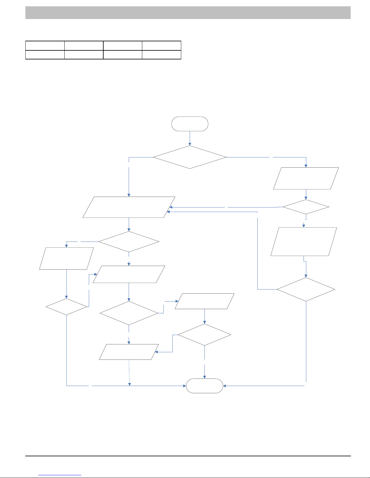
SERVICE MANUAL R−410A Ductless Split System: DLF4(A/H), DLC4(A/H)
(7) Communication malfunction
Outdoor unit malfunction indicator status
D5 D6 D16 D30
Detection:
Check if the connection wire and the built−in wiring of
indoor and outdoor unit is connected and not damaged;
If the communication circuit of indoor mainboard is
damaged? If the communication circuit of outdoor
mainboard (AP1) is damaged?
Malfunction diagnosis process:
Start
N
Connect wire of indoor
and outdoor unit
according to
circuit diagram
N
If the malfunction
is removed ?
Y
Check if the controller connection
wire inside indoor and outdoor
electric box is loose
If the connection wire
is normal?
Y
Check communication
circuit of outdoor unit
Problem of
communication
circuit
N
Replace indoor
mainboard
If the unit is operating
normally before malfunction
Y
Replace outdoor
mainboard (AP1)
If the
malfunction is
removed?
Y
N
Check connection wire
of indoor and outdoor
unit with circuit diagram
Y
N
Connection
correct?
N
Connect wire of indoor
and outdoor unit
according to
circuit diagram
If the malfunction
is removed?
Y
421 08 9204 00 77
End
Y
Page 78

SERVICE MANUAL R−410A Ductless Split System: DLF4(A/H), DLC4(A/H)
Diagnosis process for outdoor communication circuit (refer to the key detection points of outdoor unit)
Start
Test voltage
valueof Test10
position in
diagram with
voltage meter
Number jumping
N
Y
Test voltage value
of Test 13 position
in diagram with
voltage meter
Y
Number jumping
Y
Test voltage
value of Test
10 position in
diagram with
voltage meter
Number jumping
Y
Test voltage value
of Test 12 position
in diagram
with volltage
meter
Number jumping
N
Outdoor unit
malfunction
End
N
N
Y
Communication
circuit of
outdoor
unit is normal
78 421 08 9204 00
Page 79

SERVICE MANUAL R−410A Ductless Split System: DLF4(A/H), DLC4(A/H)
421 08 9204 00 79
Page 80

SERVICE MANUAL R−410A Ductless Split System: DLF4(A/H), DLC4(A/H)
80 421 08 9204 00
Page 81

SERVICE MANUAL R−410A Ductless Split System: DLF4(A/H), DLC4(A/H)
421 08 9204 00 81
 Loading...