

ICP DLF4HH12J1A, DLF4AV09J1A, DLF4HV09J1A, DLF4AH12J1A, DLC4AV12J1A Service Manual
...
R−410A Ductless Split System
Air Conditioner and Heat Pump
INTRODUCTION
SERVICE MANUAL
MODELS: DLC4(A/H)−Outdoor, DLF4(A/H)−Indoor
SIZES: 9K, 12K, 18K, 24K, 30K, and 36K
This Service Manual provides the necessary information to
service, repair, and maintain the DLF4(A,H), DLC4(A/H)
TABLE OF CONTENTS
PAGE
SAFETY CONSIDERATIONS 1........................
SPECIFICATIONS 2..................................
MODEL / SERIAL NUMBER NOMENCLATURE 16.......
STANDARD FEATURES AND ACCESSORIES 17........
DIMENSIONS 18.....................................
CLEARANCES 22....................................
SYSTEM OPERATING ENVELOPE 23..................
ELECTRICAL DATA 25...............................
CONNECTION DIAGRAMS 26.........................
WIRING DIAGRAMS 27...............................
REFRIGERATION SYSTEM DIAGRAM 36...............
REFRIGERANT LINES 38.............................
SYSTEM EVACUATION AND CHARGING 39............
CONTROL SYSTEM 40...............................
MODES OF OPERATION 44...........................
TROUBLESHOOTING 47.............................
DIAGNOSTIC CHARTS 48............................
MALFUNCTION ANALYSIS 55.........................
APPENDIX 79.......................................
SAFETY CONSIDERATIONS
Follow all safety codes. Wear safety glasses and work
gloves. Keep quenching cloth and fire extinguisher nearby
when brazing. Use care in handling, rigging, and setting
bulky equipment.
Read these instructions thoroughly and follow all warnings
or cautions included in literature and attached to the unit.
Consult local building codes and National Electrical Code
(NEC) for special requirements. In Canada, refer to current
editions of the Canadian Electrical Code, CSA 22.1.
Recognize safety information. This is the safety−alert
!
!
symbol
instructions or manuals, be alert to the potential for personal
injury.Understand these signal words: DANGER,
WARNING, and CAUTION. These words are used with the
safety−alert symbol. DANGER identifies the most serious
hazards which will result in severe personal injury or death.
WARNING signifies hazards which could result in personal
injury or death. CAUTION is used to identify unsafe
practices which may result in minor personal injury or
product and property damage. NOTE is used to highlight
suggestions which will result in enhanced installation,
reliability, or operation.
ELECTRICAL SHOCK HAZARD
Failure to follow this warning could result in personal
injury or death.
Before installing, modifying, or servicing system, main
electrical disconnect switch must be in the OFF
position. There may be more than 1 disconnect switch.
Lock out and tag switch with a suitable warning label.
. When you see this symbol on the unit and in
!
WARNING
Installing, starting up, and servicing air−conditioning
equipment can be hazardous due to system pressures,
electrical components, and equipment location (roofs,
elevated structures, etc.).
Only trained, qualified installers and service mechanics
should install, start−up, and service this equipment.
Untrained personnel can perform basic maintenance
functions such as cleaning coils. All other operations should
be performed by trained service personnel.
When working on the equipment, observe precautions in the
literature and on tags, stickers, and labels attached to the
equipment.
!
EQUIPMENT DAMAGE HAZARD
Failure to follow this caution may result in equipment
damage or improper operation.
Do not bury more than 36 in. (914 mm) of refrigerant
pipe in the ground. If any section of pipe is buried, there
must be a 6 in. (152 mm) vertical rise to the valve
connections on the outdoor units. If more than the
recommended length is buried, refrigerant may migrate
to the cooler buried section during extended periods of
system shutdown. This causes refrigerant slugging and
could possibly damage the compressor at start−up.
CAUTION
421 01 9204 00 1/03/13
SERVICE MANUAL R−410A Ductless Split System: DLF4(A/H), DLC4(A/H)
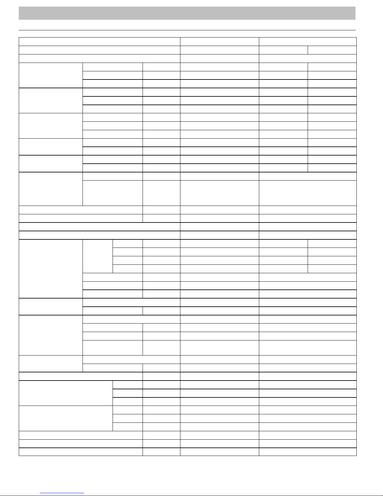
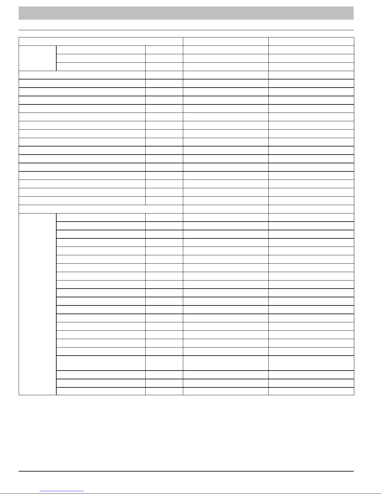
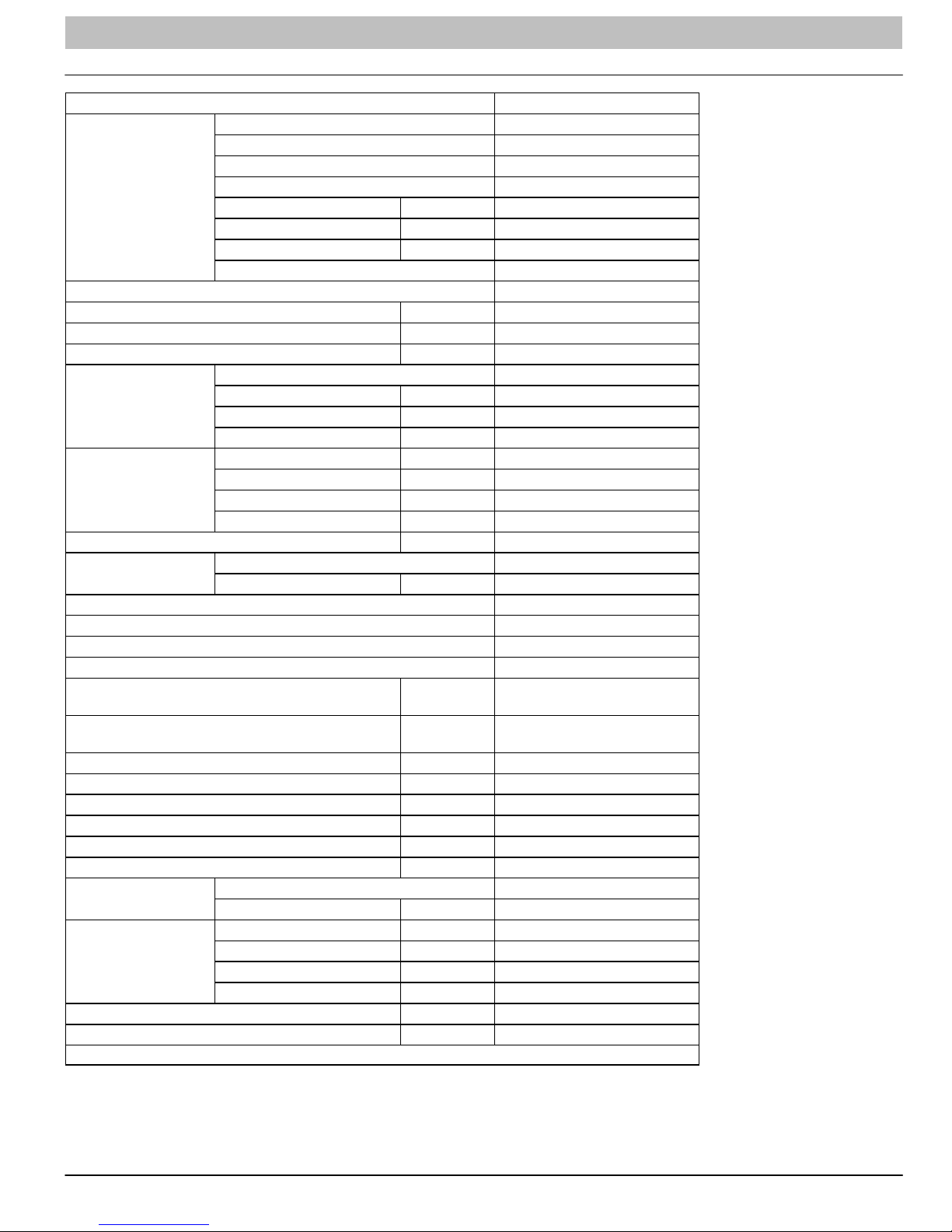
PRODUCT SPECIFICATIONS
Model − Indoor Unit DLF4AH09J1A DLF4HH09J1A
Function Cooling Cooling Heating
Rated Voltage 115V 115V
Frequency
(Inverter different
Compressor speed)
Total Capacity
(Inverter different
Compressor speed)
Power Input
(Inverter different
Compressor speed)
Rated Input
Rated Current
Air Volume
High Hz 70 70 63
Standard Hz 41 41 44
Low Hz 15 15 15
High W/Btuh 3100 / 10600 3100 / 10600 3250 / 11100
Standard W/Btuh 2650 / 9000 2650 / 9000 2820 / 9500
Low W/Btuh 1300 / 4435 1300 / 4435 930 / 3200
High W 1050 1050 1100
Standard W 634 634 700
Low W 180 180 220
High W 1050 1050 1100
Standard W 634 634 700
High A 16.8 16.8 17.0
Standard A 7.0 7.0 7.5
CFM 370 370
Dehumidifying Volume I/h 0.8 0.8
EER / C.O.P 14.2 14.2
SEER / HSPF 22 22 / 9.8
Indoor Unit DLF4AH09J1A DLF4HH09J1A
SH r/min 1260 1260 1320
Speed
Fan Motor
Output W 20 20
Capacitor mF 4.0 4.0
RLA A 0.38 0.38
Fan
Evaporator
Swing Motor
Fuse A 3.15 3.15
Sound Pressure Level
Sound Pressure Level
Dimension (WxHxD) Inch 33 x 11 x 7 33 x 11 x 7
Dimension of Package (WxHxD) Inch 36 x 14 x 10 36 x 14 x 10
Net Weight / Gross Weight Inch 29 / 38 29 / 38
Type Cross Flow Fan Cross Flow Fan
Diameter−Length Inch f3.6x25.4 f3.6x25.4
Pipe Diameter Inch f0.3 f0.3
Row−Fin Gap Inch 2−0.06 2−0.06
Coil length (I) x height
(H) x coil width (L)
Model MP24AA MP24AA
Output W 2.4 2.4
H r/min 1050 1050 1200
M r/min 920 920 1100
L r/min 730 730 950
Aluminum Fin Copper Tube Aluminum Fin Copper Tube
Inch 25.4 x 10.5 x 1 25.4 x 10.5 x 1
H dB (A) 34 34
M dB (A) 30 30
L dB (A) 26 26
H dB (A) 44 44
M dB (A) 40 40
L dB (A) 36 36
2 421 01 9204 00
SERVICE MANUAL R−410A Ductless Split System: DLF4(A/H), DLC4(A/H)
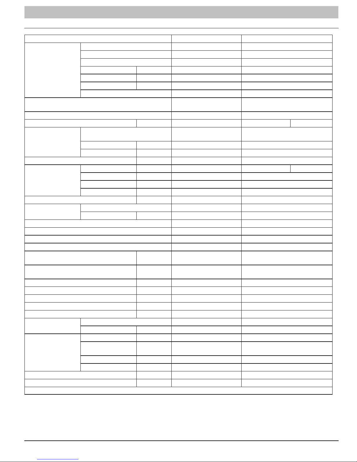
PRODUCT SPECIFICATIONS (Cont.)
Model − Outdoor Unit DLF4AV09J1A DLF4HV09J1A
Manufacturer Sanyo Sanyo
Model C−6RZ110H1A C−6RZ110H1A
Type Twin Rotary Twin Rotary
Compressor
Throttling Method
Starting Method Transducer Starting Transducer Starting
Working Temperature Range °F 55 ~ 115 55 ~ 11 5 5 ~ 24
Heat Exchanger Coil
Coil Length (I) x Height (H) x Width (L) inch 31.5 x 19.5 x.05 31.5 x 19.5 x.05
Fan Motor
Air Flow Volume of Outdoor Unit Ft3/min 1118 1118
Fan
Defrosting Method / /
Climate Type T1 T1
Isolation I I
Moisture Protection IP24 IP24
Permissible Excessive Operating Pressure for
the Discharge Side
Permissible Excessive Operating Pressure for
the Suction Side
Sound Pressure Level DB (A) ≤50 ≤50
Sound Power Level DB (A) ≤63 ≤63
Dimensions (WxHxD) inch 33 X 21 X 12.6 33 X 21 X 12.6
Dimensions of Package (WxHxD) inch 34.5 X 22.8 X 14.2 34.5 X 22.8 X 14.2
Net Weight / Gross Weight Lbs. 96 / 110 96 / 110
Refrigerant
Connection Pipe
Max. Interunit height Difference Ft. 33 33
Max. Interunit Piping Length Ft. 66 66
* The above data is subject to change without notice. Please refer to the nameplate of the unit.
L.R.A. A 33 33
R.L.A. A 4.59 / 2.81 4.59 / 2.81
Power Input W 775 / 735 775 / 735
Overload Protectorr Int11I−3979 Int11I−3979
Electronic Expansion Valve
Throttling
Coil
Pipe Diameter inch f0.3 f0.3
Rows−Fin Gap inch 2−0.06 2−0.06
Speed rpm 900 / 650 900 / 650 900
Output of Fan Motor W 40 40
R.L.A. A 0.17 0.17
Capacitor mF / /
Type Axial Fan Axial Fan
Diameter inch 15.7 15.7
Mpa 3.8 3.8
Mpa 1.2 1.2
Name of Refrigerant R410A R410A
Weight Oz. 42 42
Length (m) Ft. 16 16
Gas Additional
Charge
Liquid Pipe Diameter inch f1/4 f1/4
Gas Pipe Diameter inch f3/8 f3/8
Oz/ft 1.1613 1.1613
Aluminum Fin−Copper
Tube
Electronic Expansion Valve Throttling
Aluminum Fin−Copper Tube
421 08 9204 00 3
SERVICE MANUAL R−410A Ductless Split System: DLF4(A/H), DLC4(A/H)
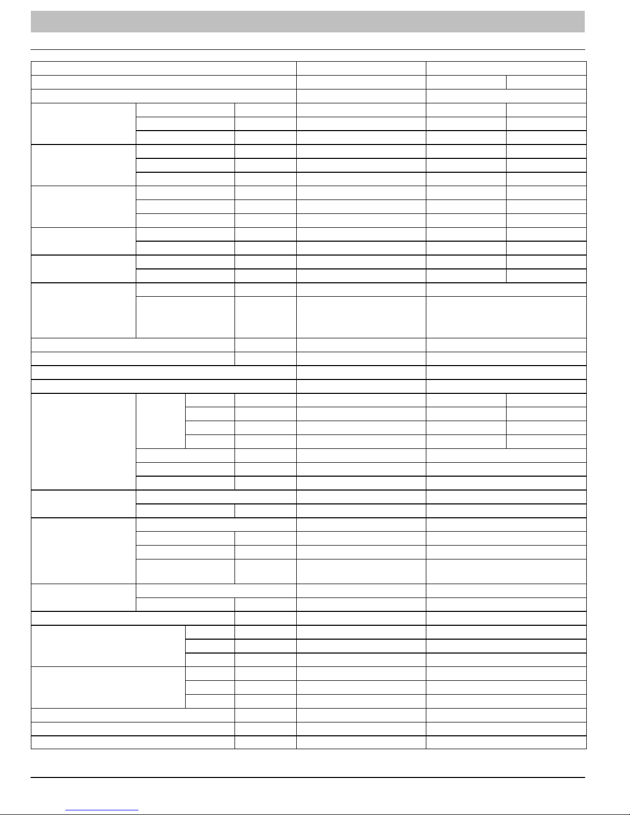
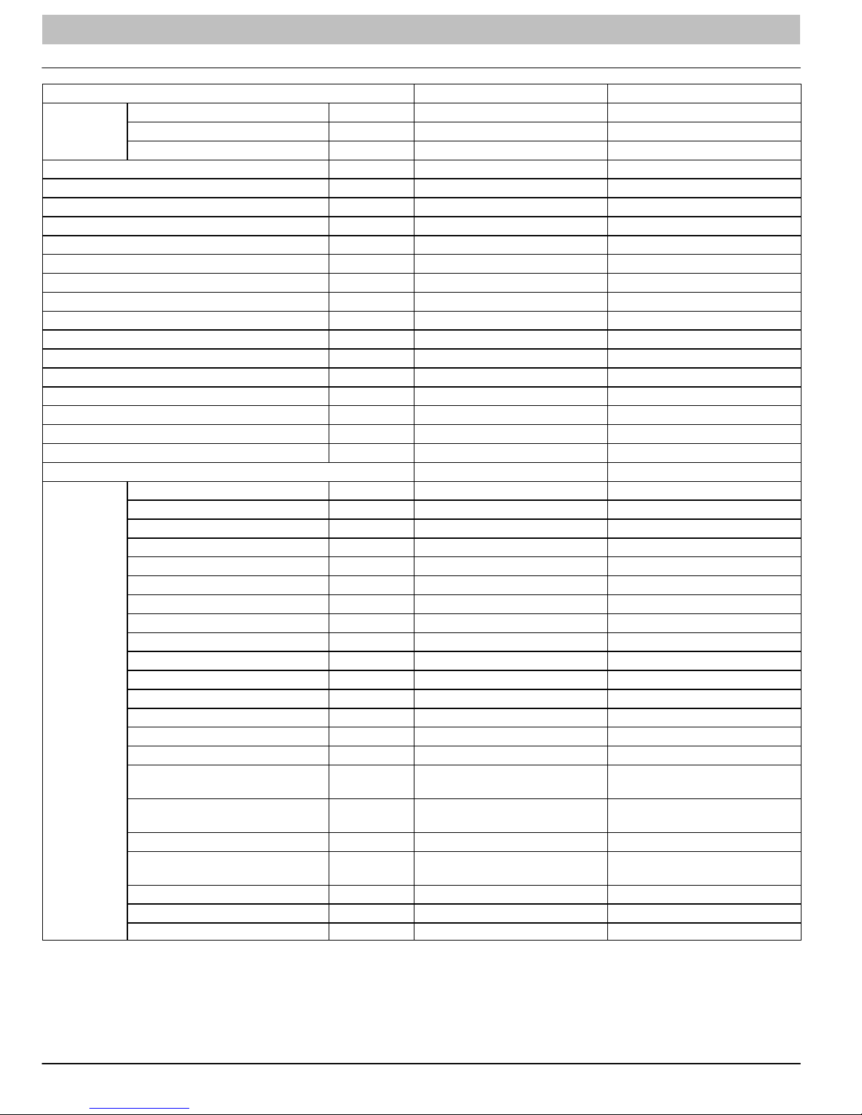
PRODUCT SPECIFICATIONS
Model − Indoor Unit DLF4AH12J1A DLF4HH12J1A
Function Cooling Cooling Heating
Rated Voltage 115V 115V
Frequency
(Inverter different
Compressor speed)
Total Capacity
(Inverter different
Compressor speed)
Power Input
(Inverter different
Compressor speed)
Rated Input
Rated Current
Air Volume
High Hz 70 70 63
Standard Hz 41 41 44
Low Hz 15 15 15
High W/Btuh 3100 / 10600 3100 / 10600 3250 / 11100
Standard W/Btuh 2650 / 9000 2650 / 9000 2820 / 9500
Low W/Btuh 1300 / 4435 1300 / 4435 930 / 3200
High W 1050 1050 1100
Standard W 634 634 700
Low W 180 180 220
High W 1050 1050 1100
Standard W 634 634 700
High A 16.8 16.8 17.0
Standard A 7.0 7.0 7.5
CFM 370 370
Dehumidifying Volume I/h 0.8 0.8
EER / C.O.P 14.2 14.2
SEER / HSPF 22 22 / 9.8
Indoor Unit DLF4AH12J1A DLF4HH12J1A
SH r/min 1260 1260 1320
Speed
Fan Motor
Output W 20 20
Capacitor mF 4.0 4.0
RLA A 0.38 0.38
Fan
Evaporator
Swing Motor
Fuse A 3.15 3.15
Sound Pressure Level
Sound Pressure Level
Dimension (WxHxD) Inch 33 x 11 x 7 33 x 11 x 7
Dimension of Package (WxHxD) Inch 36 x 14 x 10 36 x 14 x 10
Net Weight / Gross Weight Inch 29 / 38 29 / 38
Type Cross Flow Fan Cross Flow Fan
Diameter−Length Inch f3.6x25.4 f3.6x25.4
Pipe Diameter Inch f0.3 f0.3
Row−Fin Gap Inch 2−0.06 2−0.06
Coil length (I) x height
(H) x coil width (L)
Model MP24AA MP24AA
Output W 2.4 2.4
H r/min 1050 1050 1200
M r/min 920 920 1100
L r/min 730 730 950
Aluminum Fin Copper Tube Aluminum Fin Copper Tube
Inch 25.4 x 10.5 x 1 25.4 x 10.5 x 1
H dB (A) 34 34
M dB (A) 30 30
L dB (A) 26 26
H dB (A) 44 44
M dB (A) 40 40
L dB (A) 36 36
4 421 08 9204 00

SERVICE MANUAL R−410A Ductless Split System: DLF4(A/H), DLC4(A/H)
PRODUCT SPECIFICATIONS (Cont.)
Model − Outdoor Unit DLC4AV12J1A DLC4HV12J1A
Manufacturer Sanyo Sanyo
Model C−6RZ110H1A C−6RZ110H1A
Type Twin Rotary Twin Rotary
Compressor
Throttling Method
Starting Method Transducer Starting Transducer Starting
Working Temperature Range °F 55 ~ 115 55 ~ 11 5 5 ~ 75
Heat Exchanger Coil
Coil Length (I) x Height (H) x Width (L) inch 30.2 x 20 x0.9 30.2 x 20 x0.9
Fan Motor
Air Flow Volume of Outdoor Unit Ft3/min 111 8 1118
Fan
Defrosting Method / Auto Defrost
Climate Type T1 T1
Isolation I I
Moisture Protection IP24 IP24
Permissible Excessive Operating Pressure for
the Discharge Side
Permissible Excessive Operating Pressure for
the Suction Side
Sound Pressure Level DB (A) ≤53 ≤53
Sound Power Level DB (A) ≤65 ≤65
Dimensions (WxHxD) inch 33 X 21 X 12.6 33 X 21 X 12.6
Dimensions of Package (WxHxD) inch 34.5 X 22.8 X 14.2 34.5 X 22.8 X 14.2
Net Weight / Gross Weight Lbs. 107 / 118 107 / 118
Refrigerant
Connection Pipe
Max. Interunit height Difference Ft. 33 33
Max. Interunit Piping Length Ft. 66 66
* The above data is subject to change without notice. Please refer to the nameplate of the unit.
L.R.A. A 33 33
R.L.A. A 4.59 / 2.81 4.59 / 2.81
Power Input W 775 / 735 775 / 735
Overload Protectorr Int11I−3979 Int11I−3979
Electronic Expansion Valve
Throttling
Coil
Pipe Diameter inch f0.4 f0.4
Rows−Fin Gap inch 2−0.06 2−0.06
Speed rpm 900 / 680 900 / 680 900
Output of Fan Motor W 40 40
R.L.A. A 0.17 0.17
Capacitor mF / /
Type Axial Fan Axial Fan
Diameter inch 15.7 15.7
Mpa 3.8 3.8
Mpa 1.2 1.2
Name of Refrigerant R410A R410A
Weight Oz. 45.5 45.5
Length (m) Ft. 16 16
Gas Additional
Charge
Liquid Pipe Diameter inch f1/4 f1/4
Gas Pipe Diameter inch f3/8 f3/8
Oz/ft 1.1613 1.1613
Aluminum Fin−Copper
Tube
Electronic Expansion Valve Throttling
Aluminum Fin−Copper Tube
421 08 9204 00 5

SERVICE MANUAL R−410A Ductless Split System: DLF4(A/H), DLC4(A/H)
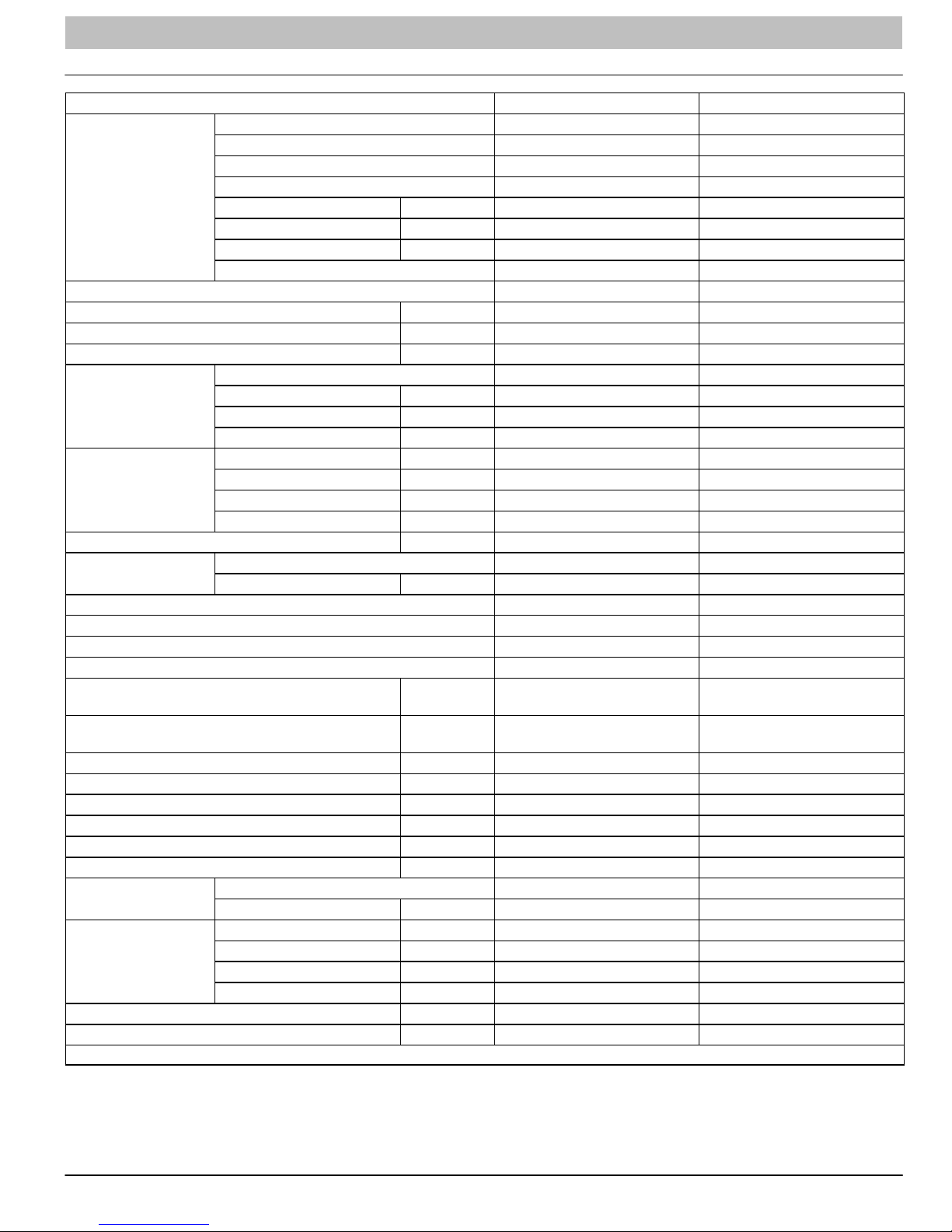
PRODUCT SPECIFICATIONS (Cont.)
Model DLC4AV12K1A DLC4HV12K1A
Power
Supply
Power Supply Mode Outdoor Outdoor
Cooling Capacity (Min − Max) Btu/h 12000 (3100−13000) 12000 (3100−13000)
Heating Capacity (Min. − Max) Btu/h N/A 13000 (2400−14000)
Cooling Power Input (Min. − Max.) W 1000 (365−1080) 1000 (365−1080)
Heating Power Input (Min. − Max.) W N/A 1000 (340−1360)
Cooling Current Input A 4.5 4.5
Heating Current Input A N/A 5.2
Rated Input W 1500 1500
Rated Current A 15 15
Air Flow Volume (S/H/M/L) CFM 335/277/253/218 335/277/253/218
Dehumidifying Volume Pint/h 2.959 2.959
EER Btu/hW 12 12
COP Btu/hW N/A 10.8
SEER 20 20
HSPF N/A 9.2
Application Area m
Model − Indoor Unit DLF4AH12K1A DLF4HH12K1A
Indoor Unit
Rated Voltage V~ 208/230 208/230
Rated Frequency Hz 60 60
Phases 1 1
2
Fan Type Cross−flow Cross−flow
Fan Diameter Length (DXL) inch f3.6x25.4 f3.6x25.4
Cooling Speed (S/H/M/L) r/min 1330/1100/950/750 1330/1100/950/750
Heating Speed (S/H/M/L) r/min N/A 1350/1170/1050/950
Fan Motor Power Output W 20 20
Fan Motor RLA A 0.2 0.2
Fan Motor Capacitor mF 1 1
Evaporator Form W Aluminum Fin−Copper Tube Aluminum Fin−Copper Tube
Evaporator Pipe Diameter inch f0.27 f0.27
Evaporator Row−fin Gap inch 2−0.05 2−0.05
Evaporator Coil Length (LxDxW) inch 22.8x1x10.4 22.8x1x10.4
Swing Motor Model MP24AA MP24AA
Swing Motor Power Output W 2.4 2.4
Fuse Current A 3.15 3.15
Sound Pressure Level (S/H/M/L) dB (A) 42/39/36/33 42/39/36/33
Sound Power Level (S/H/M/L) dB (A) 52/49/46/43 52/49/46/43
Dimension (WxHxD) inch 33.3X10.8X7 33.3X10.8X7
Dimension of Carton Box
(WxHxD)
Dimension of Package (WxHxD) inch 36X10.1X14.6 36X10.1X14.6
Net Weight lb 22 22
Gross Weight lb 28.7 28.7
inch 36X10X14 36X10X14
16−24 16−24
6 421 08 9204 00

SERVICE MANUAL R−410A Ductless Split System: DLF4(A/H), DLC4(A/H)
PRODUCT SPECIFICATIONS (Cont.)
Model − Outdoor Unit DLC4AV12K1A DLC4HV12K1A
Manufacturer Mitsubishi Mitsubishi
Model KNB092FTAMC KNB092FTAMC
Oil FV50S FV50S
Compressor
Throttling Method Electronic Expansion Valve Electronic Expansion Valve
Set Temperature Range °F 60.8 ~ 86 60.8 ~ 86
Cooling Operation Ambient Temperature Range °F 0.4 ~ 109.4 0.4 ~ 109.4
Heating Operation Ambient Temperature Range °F N/A −5 ~ 75.0
Condenser
Fan Motor
Air Flow Volume of Outdoor Unit CFM 941.6 941.6
Fan
Defrosting Method N/A Automatic Defrosting
Climate Type T1 T1
Isolation I I
Moisture Protection IP24 IP24
Permissible Excessive Operating Pressure for the
Discharge Side
Permissible Excessive Operating Pressure for the
Suction Side
Sound Pressure Level (H/M/L) DB (A) 52/−/− 52/−/−
Sound Power Level (H/M/L) DB (A) 62/−/− 62/−/−
Dimensions (WxHxD) inch 33.4x23.2x12.6 33.4x23.2x12.6
Dimensions of Carton Box (WxHxD) inch 34.5x14.2x24.8 34.5x14.2x24.8
Dimensions of Package (WxHxD) inch 34.7x14.3x25.4 34.7x14.3x25.4
Net Weight / Gross Weight Lbs. 88.2 / 97.02 88.2 / 97.02
Refrigerant
Connection Pipe
Max. Interunit height Difference Ft. 33 33
Max. Interunit Piping Length Ft. 66 66
* The above data is subject to change without notice. Please refer to the nameplate of the unit.
Type Rotary Rotary
L.R.A. A 13.8 13.8
R.L.A. A 3.2 3.2
Power Input W 860 860
Overload Protector INT11L−6578 INT11L−6578
Form Aluminum Fin−copper Tube Aluminum Fin−copper Tube
Pipe Diameter inch f0.37 f0.37
Rows−Fin Gap inch 2−0.05 2−0.05
Coil Length (LxDxW) inch 29.4x1.7x22 29.4x1.7x22
Speed rpm 680 / 900 680 / 900
Output of Fan Motor W 30 30
R.L.A. A 0.13 0.13
Capacitor mF N/A N/A
Type Axial Flow Axial Flow
Diameter inch 15.748 15.748
Mpa 4.3 4.3
Mpa 2.5 2.5
Name of Refrigerant R410A R410A
Weight Oz. 45.864 45.864
Length inch 25 25
Gas Additional Charge Oz/ft 0.53 0.7
Liquid Pipe Outer Diameter inch 1/4 1/4
Gas Pipe Outer Diameter inch 3/8 3/8
421 08 9204 00 7
SERVICE MANUAL R−410A Ductless Split System: DLF4(A/H), DLC4(A/H)
PRODUCT SPECIFICATIONS (Cont.)
Model DLC4AV18K1A DLC4HV18K1A
Power
Supply
Power Supply Mode Outdoor Outdoor
Cooling Capacity (Min − Max) Btu/h 18000 (5970−22350) 18000 (5970−22350)
Heating Capacity (Min. − Max) Btu/h N/A 19800 (4100−22000)
Cooling Power Input (Min. − Max.) W 1500 (300−2650) 1500 (300−2650)
Heating Power Input (Min. − Max.) W N/A 1650 (335−2750)
Cooling Current Input A 6.65 6.65
Heating Current Input A N/A 7.32
Rated Input W 2650 2750
Rated Current A 11.757 12.201
Air Flow Volume (S/H/M/L) CFM 500/459/383/324 500/459/383/324
Dehumidifying Volume Pint/h 0.852 0.852
EER Btu/hW 12 12
COP Btu/hW N/A 12
SEER 18 18
HSPF N/A 10
Application Area m
Model − Indoor Unit DLF4AH18K1A DLF4HH18K1A
Indoor Unit
Rated Voltage V~ 208/230 208/230
Rated Frequency Hz 60 60
Phases 1 1
2
Fan Type Cross−flow Cross−flow
Fan Diameter Length (DXL) inch f3.86x28 f3.86x28
Cooling Speed (S/H/M/L) r/min 1500/1200/1050/900 1500/1200/1050/900
Heating Speed (S/H/M/L) r/min N/A 1500/1250/1150/1050
Fan Motor Power Output W 20 20
Fan Motor RLA A 0.32 0.32
Fan Motor Capacitor mF 1.5 1.5
Evaporator Form W Aluminum Fin−Copper Tube Aluminum Fin−Copper Tube
Evaporator Pipe Diameter inch f0.27 f0.27
Evaporator Row−fin Gap inch 2−0.05 2−0.05
Evaporator Coil Length (LxDxW) inch 28x1x12 28x1x12
Swing Motor Model MP28VB MP28VB
Swing Motor Power Output W 2.5 2.5
Fuse Current A 3.15 3.15
Sound Pressure Level (S/H/M/L) dB (A) 49/44/40/35 49/44/40/35
Sound Power Level (S/H/M/L) dB (A) 59/54/50/45 59/54/50/45
Dimension (WxHxD) inch 37X11.7X7.9 37X11.7X7.9
Dimension of Carton Box
(WxHxD)
Dimension of Package (WxHxD) inch 39.7X11.2X15 39.7X11.2X15
Net Weight lb 28.665 28.665
Gross Weight lb 37.485 37.485
inch 39.6X11.1X14.4 39.6X11.1X14.4
27−42 27−42
8 421 08 9204 00

SERVICE MANUAL R−410A Ductless Split System: DLF4(A/H), DLC4(A/H)
PRODUCT SPECIFICATIONS (Cont.)
Model − Outdoor Unit DLC4AV18K1A DLC4HV18K1A
Manufacturer Mitsubishi Mitsubishi
Model SNB130FGAMC SNB130FGAMC
Oil FV50S−PVE FV50S−PVE
Compressor
Throttling Method Electronic Expansion Valve Electronic Expansion Valve
Set Temperature Range °F 61 ~ 86 61 ~ 86
Cooling Operation Ambient Temperature Range °F 14 ~ 109.0 14 ~ 109.0
Heating Operation Ambient Temperature Range °F N/A 19.4 − 75.0
Condenser
Fan Motor
Air Flow Volume of Outdoor Unit CFM 1883.2 1883.2
Fan
Defrosting Method N/A Automatic Defrosting
Climate Type T1 T1
Isolation I I
Moisture Protection IP24 IP24
Permissible Excessive Operating Pressure for the
Discharge Side
Permissible Excessive Operating Pressure for the
Suction Side
Sound Pressure Level (H/M/L) DB (A) 55/−/− 55/−/−
Sound Power Level (H/M/L) DB (A) 65/−/− 65/−/−
Dimensions (WxHxD) inch 37.6x27.6x15.6 37.6x27.6x15.6
Dimensions of Carton Box (WxHxD) inch 40.4x18x29 40.4x18x29
Dimensions of Package (WxHxD) inch 40.5x18x29.5 40.5x18x29.5
Net Weight / Gross Weight Lbs. 99.225 / 110.25 99.225 / 110.25
Refrigerant
Connection Pipe
Max. Interunit height Difference Ft. 33 33
Max. Interunit Piping Length Ft. 82 82
* The above data is subject to change without notice. Please refer to the nameplate of the unit.
Type Rotary Rotary
L.R.A. A 13.8 13.8
R.L.A. A 4.1 4.1
Power Input W 1200 1200
Overload Protector INT11L−6578 INT11L−6578
Form Aluminum Fin−copper Tube Aluminum Fin−copper Tube
Pipe Diameter inch f0.37 f0.37
Rows−Fin Gap inch 2−0.05 2−0.05
Coil Length (LxDxW) inch 33x1.5x26 33x1.5x26
Speed rpm 800 800
Output of Fan Motor W 60 60
R.L.A. A 0.28 0.28
Capacitor mF N/A N/A
Type Axial Flow Axial Flow
Diameter inch 20.472 20.472
Mpa 4.3 4.3
Mpa 2.5 2.5
Name of Refrigerant R410A R410A
Weight Oz. 49.392 49.392
Length inch 25 25
Gas Additional Charge Oz/ft 0.2 0.2
Liquid Pipe Outer Diameter inch 1/4 1/4
Gas Pipe Outer Diameter inch 1/2 1/2
421 08 9204 00 9

SERVICE MANUAL R−410A Ductless Split System: DLF4(A/H), DLC4(A/H)
PRODUCT SPECIFICATIONS (Cont.)
Model DLC4AV24K1A DLC4HV24K1A
Power
Supply
Power Supply Mode Outdoor Outdoor
Cooling Capacity (Min − Max) Btu/h 21400 (9600−25000) 21400 (9600−25000)
Heating Capacity (Min. − Max) Btu/h N/A 23000 (4300−26000)
Cooling Power Input (Min. − Max.) W 1780 (500−2650) 1780 (500−2650)
Heating Power Input (Min. − Max.) W N/A 2100 (400−2750)
Cooling Current Input A 7.941 7.941
Heating Current Input A N/A 9.317
Rated Input W 2650 2750
Rated Current A 11.757 12.201
Air Flow Volume (S/H/M/L) CFM 589/471/412/353 589/471/412/353
Dehumidifying Volume Pint/h 1.183 1.183
EER Btu/hW 12 12
COP Btu/hW N/A 10.95
SEER 18 18
HSPF N/A 10
Application Area m
Model − Indoor Unit DLF4AH24K1A DLF4HH24K1A
Indoor Unit
Rated Voltage V~ 208/230 208/230
Rated Frequency Hz 60 60
Phases 1 1
2
Fan Type Cross−flow Cross−flow
Fan Diameter Length (DXL) inch f3.86x30 f3.86x30
Cooling Speed (S/H/M/L) r/min 1500/1200/1050/900 1500/1200/1050/900
Heating Speed (S/H/M/L) r/min N/A 1450/1150/1020/950
Fan Motor Power Output W 260 260
Fan Motor RLA A 0.24 0.24
Fan Motor Capacitor mF N/A N/A
Evaporator Form W Aluminum Fin−Copper Tube Aluminum Fin−Copper Tube
Evaporator Pipe Diameter inch f0.27 f0.27
Evaporator Row−fin Gap inch 2−0.06 2−0.06
Evaporator Coil Length (LxDxW) inch 30x1x15.5 30x1x15.5
Swing Motor Model MP35XX MP35XX
Swing Motor Power Output W 3 3
Fuse Current A 3.15 3.15
Sound Pressure Level (S/H/M/L) dB (A) 53/45/41/37 53/45/41/37
Sound Power Level (S/H/M/L) dB (A) 63/55/51/47 63/55/51/47
Dimension (WxHxD) inch 39.7X12.4X8.6 39.7X12.4X8.6
Dimension of Carton Box
(WxHxD)
Dimension of Package (WxHxD) inch 42.4X15.7X12.9 42.4X15.7X12.9
Net Weight lb 35.28 35.28
Gross Weight lb 46.305 46.305
inch 42.2X15.5X12.3 42.2X15.5X12.3
27−42 27−42
10 421 08 9204 00

SERVICE MANUAL R−410A Ductless Split System: DLF4(A/H), DLC4(A/H)
PRODUCT SPECIFICATIONS (Cont.)
Model − Outdoor Unit DLC4AV24K1A DLC4HV24K1A
Manufacturer Mitsubishi Mitsubishi
Model SNB150FGAMC SNB150FGAMC
Oil FV50S−PVE FV50S−PVE
Compressor
Throttling Method Electronic Expansion Valve Electronic Expansion Valve
Set Temperature Range °F 61 ~ 86 61 ~ 86
Cooling Operation Ambient Temperature Range °F 5 ~ 109.0 5 ~ 109.0
Heating Operation Ambient Temperature Range °F N/A 19.4 − 75.0
Condenser
Fan Motor
Air Flow Volume of Outdoor Unit CFM 2354 2354
Fan
Defrosting Method N/A N/A
Climate Type T1 T1
Isolation I I
Moisture Protection IP24 IP24
Permissible Excessive Operating Pressure for the
Discharge Side
Permissible Excessive Operating Pressure for the
Suction Side
Sound Pressure Level (H/M/L) DB (A) 56/−/− 56/−/−
Sound Power Level (H/M/L) DB (A) 66/−/− 66/−/−
Dimensions (WxHxD) inch 38.6x31.1x16.8 38.6x31.1x16.8
Dimensions of Carton Box (WxHxD) inch 42.5x19x33 42.5x19x33
Dimensions of Package (WxHxD) inch 42.6x19x33.7 42.6x19x33.7
Net Weight / Gross Weight Lbs. 119 / 132 119 / 132
Refrigerant
Connection Pipe
Max. Interunit height Difference Ft. 33 33
Max. Interunit Piping Length Ft. 82 82
* The above data is subject to change without notice. Please refer to the nameplate of the unit.
Type Rotary Rotary
L.R.A. A 18.5 18.5
R.L.A. A 4.9 4.9
Power Input W 1420 1420
Overload Protector INT11L−6578 INT11L−6578
Form Aluminum Fin−copper Tube Aluminum Fin−copper Tube
Pipe Diameter inch f0.27 f0.27
Rows−Fin Gap inch 2−0.05 2−0.05
Coil Length (LxDxW) inch 38x1.5x29 38x1.5x29
Speed rpm 800 800
Output of Fan Motor W 90 90
R.L.A. A 1.1 1.1
Capacitor mF 4 4
Type Axial Flow Axial Flow
Diameter inch 21.732 21.732
Mpa 4.3 4.3
Mpa 2.5 2.5
Name of Refrigerant R410A R410A
Weight Oz. 56.448 56.448
Length inch 25 25
Gas Additional Charge Oz/ft 0.2 0.2
Liquid Pipe Outer Diameter inch 1/4 1/4
Gas Pipe Outer Diameter inch 5/8 5/8
421 08 9204 00 11
SERVICE MANUAL R−410A Ductless Split System: DLF4(A/H), DLC4(A/H)
PRODUCT SPECIFICATIONS (Cont.)
Model DLF4HH30K1A DLF4HH36K1A
Power
Supply
Power Supply Mode Outdoor Outdoor
Cooling Capacity (Min − Max) Btu/h 28000 (9500−30000) 33600 (7400−36000)
Heating Capacity (Min. − Max) Btu/h 28400 (10000−33000) 34600 (1500−36000)
Cooling Power Input (Min. − Max.) W 2780 (350−3400) 3650 (450−3800)
Heating Power Input (Min. − Max.) W 2870 (450−3300) 3560 (560−3700)
Cooling Current Input A 12.1 16.6
Heating Current Input A 12.5 9.21
Rated Input W 3475 4000
Rated Current A 16.7 18.2
Air Flow Volume (S/H/M/L) CFM −/706/677/647/− −/824/706/677/−
Dehumidifying Volume Pint/h 1.42 1.166
EER Btu/hW 10.7 9.21
COP Btu/hW 9.93 9.72
SEER 16 16
HSPF 8.2 8.2
Application Area m
Model − Indoor Unit DLC4HV30K1A DLC4HH36K1A
Indoor Unit
Rated Voltage V~ 208/230 208/230
Rated Frequency Hz 60 60
Phases 1 1
2
Fan Type Cross−flow Cross−flow
Fan Diameter Length (DXL) inch f4.25x20.58X2 f4.25x20.58X2
Cooling Speed (SH/H/ML/SL) r/min −/1410/1280/1200/− −1550/1400/1300/−
Heating Speed (SH/H/ML/SL) r/min −/1410/1280/1200/− −1550/1400/1300/−
Fan Motor Power Output W 40 60
Fan Motor RLA A 0.4 0.47
Fan Motor Capacitor mF 3.5 3.5
Input of Heater W − −
Evaporator Form W Aluminum Fin−Copper Tube Aluminum Fin−Copper Tube
Evaporator Pipe Diameter inch f11/40 f11/40
Evaporator Row−fin Gap inch 2−0.055 2−0.055
Evaporator Coil Length (LxDxW) inch 142.3x1x15 142.3x1x15
Swing Motor Model MP24BA MP24BA
Swing Motor Power Output W 2 2
Fuse Current A 3.15 3.15
Sound Pressure Level
(SH/H/M/L/SL)
Sound Power Level
(SH/H/M/L/SL)
Dimension (WxHxD) inch 53.1X12.8X10.0 53.1X12.8X10.0
Dimension of Carton Box
(WxHxD)
Dimension of Package (WxHxD) inch 56.7X16.6X14.0 56.7X16.6X14.0
Net Weight lb 44.1 44.1
Gross Weight lb 59.5 59.5
dB (A) −/57/54/46/− −57/56/53/−
dB (A) −/57/54/46/− −/69/66/63/−
inch 56.6X16.5X13.5 56.7X16.6X14.0
377−550 495−753
12 421 08 9204 00
SERVICE MANUAL R−410A Ductless Split System: DLF4(A/H), DLC4(A/H)
PRODUCT SPECIFICATIONS (Cont.)
Model − Outdoor Unit DLC4HV30K1A DLC4HV36K1A
Manufacturer Zhuhai Landa Mitsubishi
Model QXAS−D23ZX090 TNB306FPGMCMC
Oil PVE (FV50S) FV50S
Compressor
Throttling Method Electronic Expansion Valve Electronic Expansion Valve
Set Temperature Range °F 61 ~ 86 61 ~ 86
Cooling Operation Ambient Temperature Range °F 5 ~ 109.0 5 ~ 109.0
Heating Operation Ambient Temperature Range °F 19.4−75.0 19.4 − 75.0
Condenser
Fan Motor
Air Flow Volume of Outdoor Unit CFM 2354 2589
Fan
Defrosting Method Automatic Defrosting Automatic Defrosting
Climate Type T1 T1
Isolation I I
Moisture Protection IP24 IP24
Permissible Excessive Operating Pressure for the
Discharge Side
Permissible Excessive Operating Pressure for the
Suction Side
Sound Pressure Level (H/M/L) DB (A) 62/−/− 65/−/−
Sound Power Level (H/M/L) DB (A) 72/−/− 75/−/−
Dimensions (WxHxD) inch 38.6x31.1x16.8 38.6x31.1x16.8
Dimensions of Carton Box (WxHxD) inch 42.5x19.1x33 42.5x19.1x33
Dimensions of Package (WxHxD) inch 42.6x19x33.7 42.6x19x33.7
Net Weight / Gross Weight Lbs. 154 / 163 161 / 170
Refrigerant
Connection Pipe
Max. Interunit height Difference Ft. 32.8 32.8
Max. Interunit Piping Length Ft. 98.4 98.4
* The above data is subject to change without notice. Please refer to the nameplate of the unit.
Type Rotary Rotary
L.R.A. A 40 67
R.L.A. A 12 13.5
Power Input W 2450 3010
Overload Protector INT11L−6233 CS01F272H01
Form Aluminum Fin−copper Tube Aluminum Fin−copper Tube
Pipe Diameter inch f01/3 f3/8
Rows−Fin Gap inch 2−0.055 2−0.055
Coil Length (LxDxW) inch 37.5x1.5x29.4 37x1.7x30
Speed rpm 830 900
Output of Fan Motor W 90 170
R.L.A. A 0.45 0.73
Capacitor mF N/A N/A
Type Axial Flow Axial Flow
Diameter inch f21.73 f21.73
PSI 551 551
PSI 174 174
Name of Refrigerant R410A R410A
Weight Oz. 84.7 91.7
Length inch 24.6 24.6
Gas Additional Charge Oz/ft 0.5 0.2
Liquid Pipe Outer Diameter inch f1/4 f1/4
Gas Pipe Outer Diameter inch f5/8 f5/8
421 08 9204 00 13
SERVICE MANUAL R−410A Ductless Split System: DLF4(A/H), DLC4(A/H)
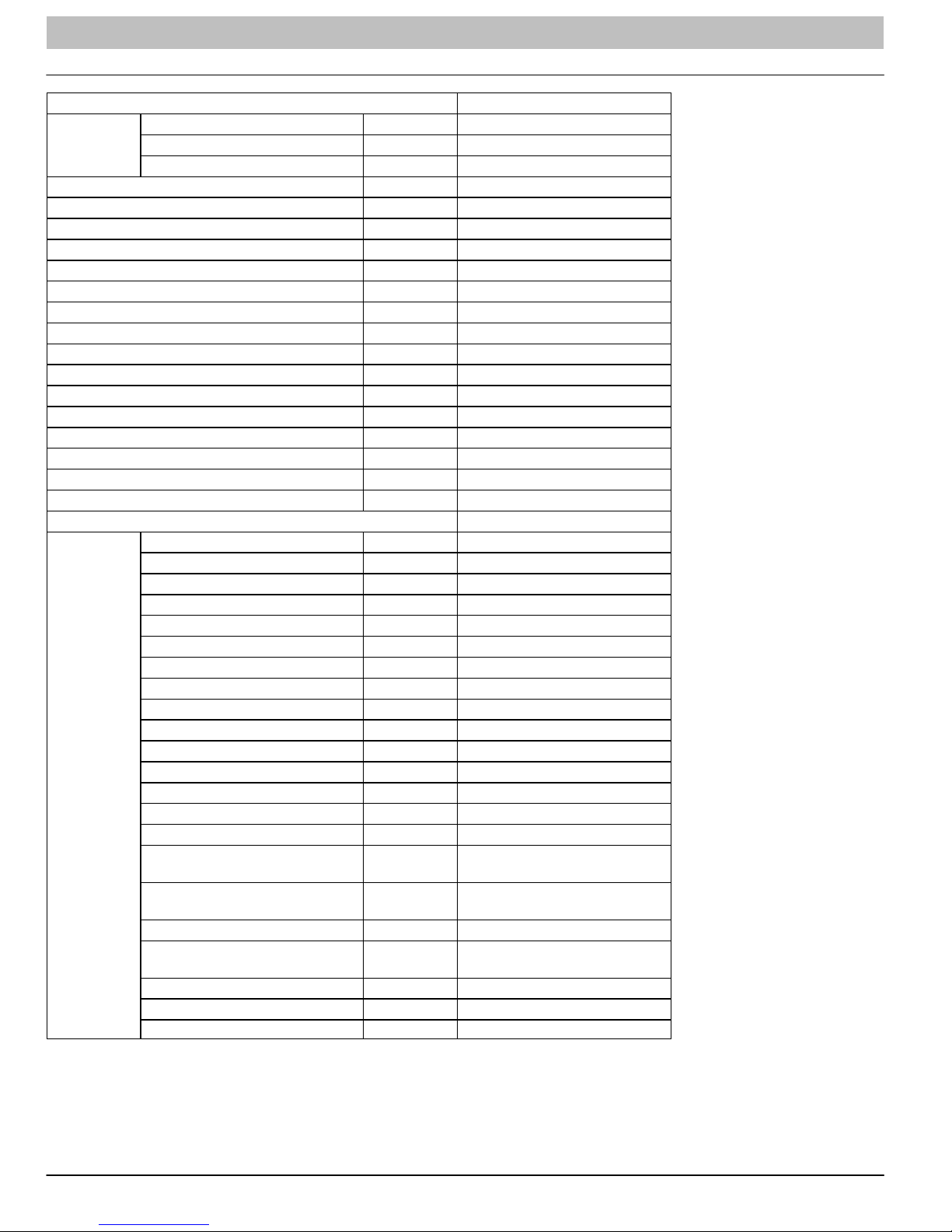
PRODUCT SPECIFICATIONS (Cont.)
Model DLF4AH36K1A
Power
Supply
Power Supply Mode Outdoor
Cooling Capacity (Min − Max) Btu/h 33600 (7400−36000)
Heating Capacity (Min. − Max) Btu/h N/A
Cooling Power Input (Min. − Max.) W 3650 (410−3800)
Heating Power Input (Min. − Max.) W N/A
Cooling Current Input A 15.9
Heating Current Input A N/A
Rated Input W 4200
Rated Current A 18.2
Air Flow Volume (S/H/M/L) CFM −/824/706/677/−
Dehumidifying Volume Pint/h 1.66
EER Btu/hW 9.21
COP Btu/hW N/A
SEER 16
HSPF N/A
Application Area m
Model − Indoor Unit DLF4AH36K1A
Indoor Unit
Rated Voltage V~ 208/230
Rated Frequency Hz 60
Phases 1
2
Fan Type Cross−flow
Fan Diameter Length (DXL) inch f4.25x20.58X2
Cooling Speed (SH/H/ML/SL) r/min −/1550/1400/12300/−
Heating Speed (SH/H/ML/SL) r/min N/A
Fan Motor Power Output W 60
Fan Motor RLA A 0.47
Fan Motor Capacitor mF 3.5
Input of Heater W N/A
Evaporator Form W Aluminum Fin−Copper Tube
Evaporator Pipe Diameter inch f11/40
Evaporator Row−fin Gap inch 2−0.055
Evaporator Coil Length (LxDxW) inch 142.3x1x15
Swing Motor Model MP24BA
Swing Motor Power Output W 2
Fuse Current A 3.15
Sound Pressure Level
(SH/H/M/L/SL)
Sound Power Level
(SH/H/M/L/SL)
Dimension (WxHxD) inch 53.1X12.8X10.0
Dimension of Carton Box
(WxHxD)
Dimension of Package (WxHxD) inch 56.7X16.6X14.0
Net Weight lb 44.1
Gross Weight lb 59.5
dB (A) −/59/56/53/−
dB (A) −/69/66/63/−
inch 56.6X16.5X13.5
495−753
14 421 08 9204 00
SERVICE MANUAL R−410A Ductless Split System: DLF4(A/H), DLC4(A/H)
PRODUCT SPECIFICATIONS (Cont.)
Model − Outdoor Unit DLC4AV36K1A
Manufacturer Mitsubishi
Model TNB306FPGMCMC
Oil FV50S
Compressor
Throttling Method Capillary
Set Temperature Range °F 61 ~ 86
Cooling Operation Ambient Temperature Range °F 5 ~ 109.0
Heating Operation Ambient Temperature Range °F 19.4 − 75.0
Condenser
Fan Motor
Air Flow Volume of Outdoor Unit CFM 2589
Fan
Defrosting Method N/A
Climate Type T1
Isolation I
Moisture Protection IP24
Permissible Excessive Operating Pressure for the
Discharge Side
Permissible Excessive Operating Pressure for the
Suction Side
Sound Pressure Level (H/M/L) DB (A) 65/−/−
Sound Power Level (H/M/L) DB (A) 75/−/−
Dimensions (WxHxD) inch 38.6x31.1x16.7
Dimensions of Carton Box (WxHxD) inch 42.5x19.1x33.1
Dimensions of Package (WxHxD) inch 42.6x19.2x33.6
Net Weight / Gross Weight Lbs. 161 / 170
Refrigerant
Connection Pipe
Max. Interunit height Difference Ft. 32.8
Max. Interunit Piping Length Ft. 98.4
* The above data is subject to change without notice. Please refer to the nameplate of the unit.
Type Rotary
L.R.A. A 67
R.L.A. A 13.5
Power Input W 3010
Overload Protector CS01F272H01
Form Aluminum Fin−copper Tube
Pipe Diameter inch f3/8
Rows−Fin Gap inch 2−0.055
Coil Length (LxDxW) inch 37x1.7x30
Speed rpm 900
Output of Fan Motor W 170
R.L.A. A 0.73
Capacitor mF N/A
Type Axial Flow
Diameter inch f21.73
PSI 551
PSI 174
Name of Refrigerant R410A
Weight Oz. 91.7
Length inch 24.6
Gas Additional Charge Oz/ft 0.2
Liquid Pipe Outer Diameter inch f1/4
Gas Pipe Outer Diameter inch f5/8
421 08 9204 00 15
SERVICE MANUAL R−410A Ductless Split System: DLF4(A/H), DLC4(A/H)
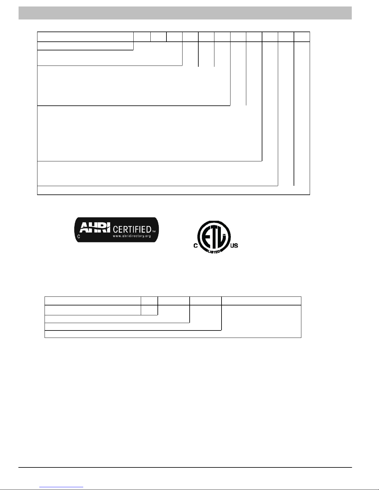
MODEL NOMENCLATURE
MODEL SERIES
Position Number 1 2 3 4 5 6 7 8 9 10 11
DLC = Outdoor
DLF = Indoor Outdoor/Indoor
4AV = AC Outdoor
4AH = AC Indoor
4HV = HP Outdoor
4HH = HP Indoor
09 = 9k BTU
12 = 12k BTU
18 = 18k BTU
24 = 24k BTU
30 = 30k BTU
36 = 36k BTU
J = 115−1−60
K = 208/230−1−60
1A Factory Designation
D L C 4 A V 0 9 J 1 A
Type
Size
Voltage
Use of the AHRI Certified TM Mark indicates a
manufacturer’s participation in the program. For
verification of certification for individual products,
go to www.ahridirectory.org .
SERIAL NUMBER NOMENCLATURE
Position Number 1 2 3 4 5 6 7 8 9 10
Serial Number
Year
Week
Sequential Digits Unique for Each Factory
V 1 0 2 2 1 2 3 4 5
16 421 08 9204 00
SERVICE MANUAL R−410A Ductless Split System: DLF4(A/H), DLC4(A/H)
STANDARD FEATURES AND ACCESSORIES
Ease of Operation
Mounting Brackets S
Low Voltage Connections S
Comfort Features
Microprocessor Controls S
Wireless Remote Control S
Rapid Cooling/Heating S
Automatic Air Sweep S
Cold Blow Prevention S
Continuous Fan S
Auto Restart Feature S
Memory Function S
Auto Changeover S
Energy Saving Features
Inverter Driven Compressor S
Sleep Mode S
24 Hour Stop/Start Timer* S
Safety and Reliability
Indoor Unit Freeze Protection S
3 Minute Compressor Time Delay S
High Compressor Discharge Temperature S
Low Voltage Protection S
Compressor Overload Protection S
Compressor Over Current Protection S
IPM Module Protection S
Ease of Service and Maintenance
Cleanable Filters S
Diagnostic LED’s ON Outdoor Board S
Error Messages Displayed Front Panel S
Application Flexibility
Condensate Pump A
Low Ambient Heating and Cooling on most models A
Standard Warranty
7 Year Compressor Limited Warranty S
5 Year Parts Limited Warranty S
Extended Warranty
6 −10 Year Compressor Only O
2 − 6 Year Parts Only O
2 − 6 Year Parts Only; 1 − 6 Year Labor O
2 − 6 Year Parts Only; 6 − 10 Year Compressor Only;
1 − 6 Year Labor
Legend
S = Standard
A = Accessory
O = Optional
* Sizes 09, 18, & 24K have a clock.
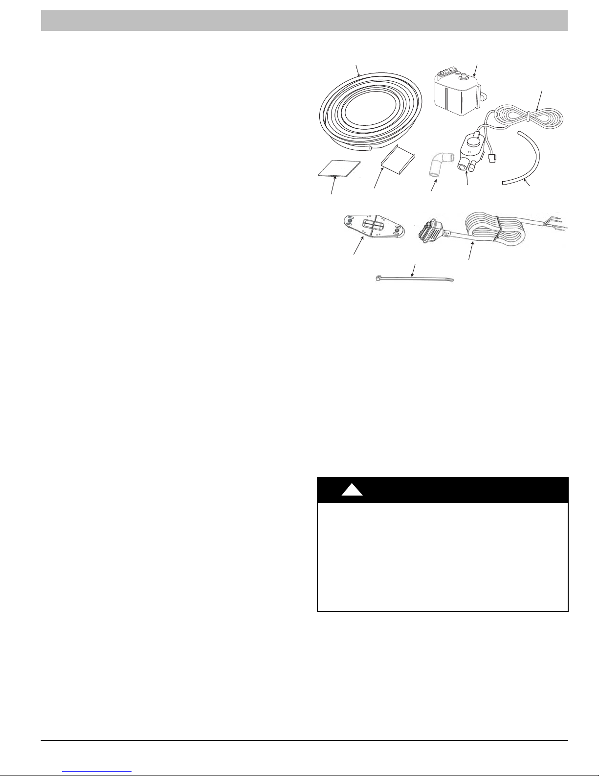
16’ Transparent
Suction Discharge Tubing
Adhesive
Mounting Bracket
Detection Unit
Mounting Bracket
5/8” Rubber Elbow
Wire Ties (6)
Figure 1 - Accessory Condensate Pump Kit
Table 1 − Accessory Condensate Pump Kit Contents
Item Qty.
16 ft Transparent Suction/Discharge Tubing 1
Condensate Pump Assembly 1
Low voltage Power Cord 1
Transparent Detection Unit Vent Tubing 1
Power Cable 1
Wire Ties 6
Wall Mount Bracket 1
Adhesive 1
Detection Unit Mounting Bracket 1
⅝−in Rubber Elbow 1
Detection Unit 1
!
ELECTRICAL SHOCK HAZARD
O
Failure to follow this warning could result in personal injury
or death.
Before installing, modifying, or servicing system, main
electrical disconnect switch must be in the OFF position.
Ensure power is disconnected to the fan coil unit. On some
systems both the fan coil and the outdoor unit may be on
the same disconnect. There may be more than 1 disconnect
switch. Lock out and tag switch with a suitable warning
label.
WARNING
Condensate Pump
Assembly
Detection Unit
Power Cable
Low Voltage
Power Cord
Transparent
Detection
Unit Vent Tubing
A12227
421 08 9204 00 17

SERVICE MANUAL R−410A Ductless Split System: DLF4(A/H), DLC4(A/H)
DIMENSIONS − INDOOR
WD
H
Unit Size
9k 33.3 (846) 10.7 (272) 7.1 (180) 29 (13)
12k 33.3 (846) 10.7 (272) 7.1 (180) 29 (13)
18k 37.0 (940) 11.7 (297) 7.9 (201) 29 (13)
24k 39.7 (1008) 12.4 (315) 8.6 (218) 35 (16)
30k 53.1 (1349) 12.8 (325) 10.0 (54) 44.1 (20.0)
36k 53.1 (1349) 12.8 (325) 10.0 (54) 44.1 (20.0)
W
In. (mm)
H
In. (mm)
D
In. (mm)
Net Operating Weight
Lbs. (Kg)
A12377
18 421 08 9204 00
SERVICE MANUAL R−410A Ductless Split System: DLF4(A/H), DLC4(A/H)
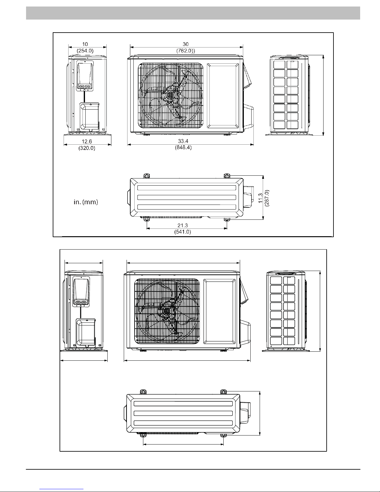
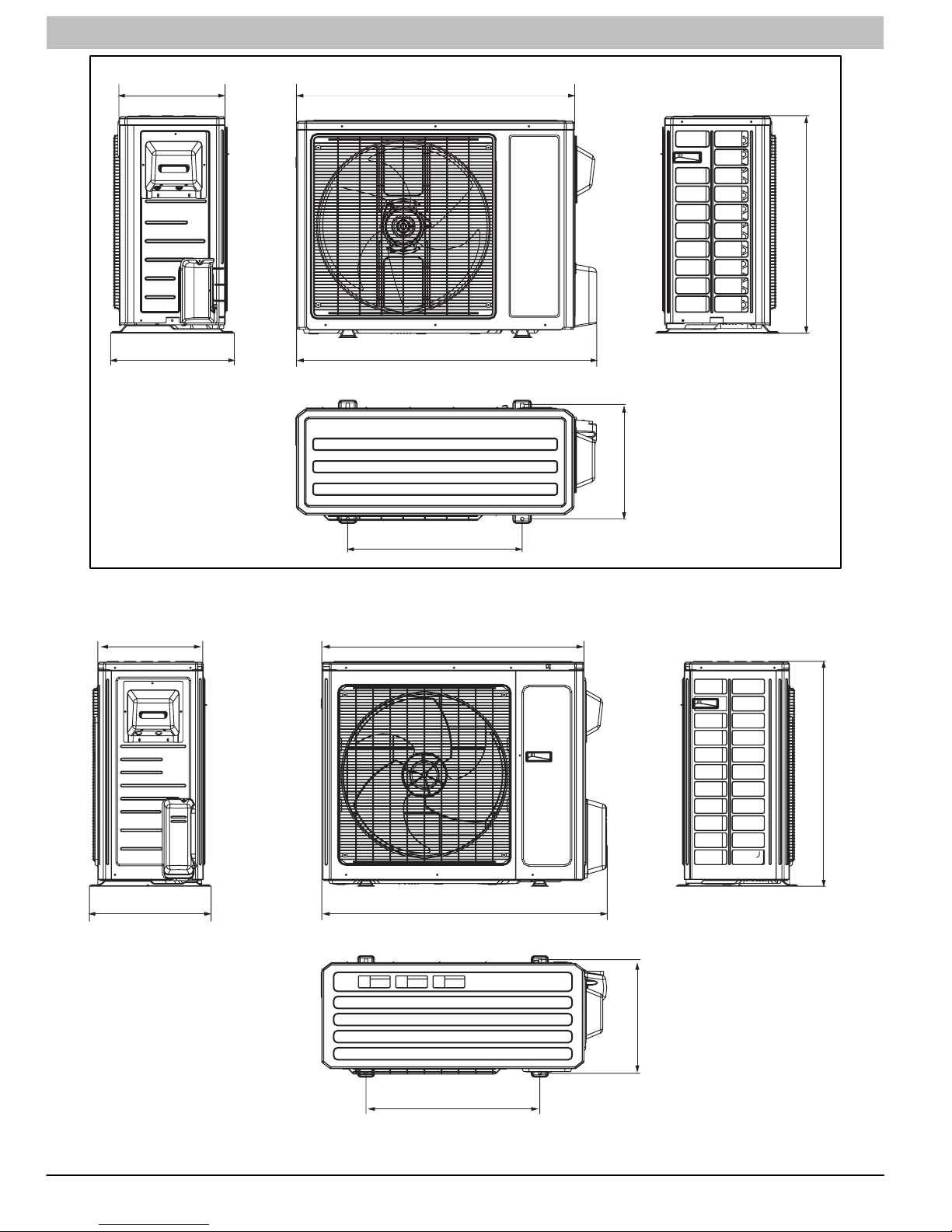
DIMENSIONS − OUTDOOR
UNIT SIZE − 09
(Net Operating Weight: 96 lbs.- 44 kg.)
21.3
(541)
10
(254.0)
12.6
(320.0)
in. (mm)
UNIT SIZE − 12
(Net Operating Weight: 107 lbs.- 49 kg.)
30
(762.0))
33.4
(848.4)
11.3
(287.0)
23.2
A12380
(589.3)
421 08 9204 00 19
21.3
(541.0)
A12381
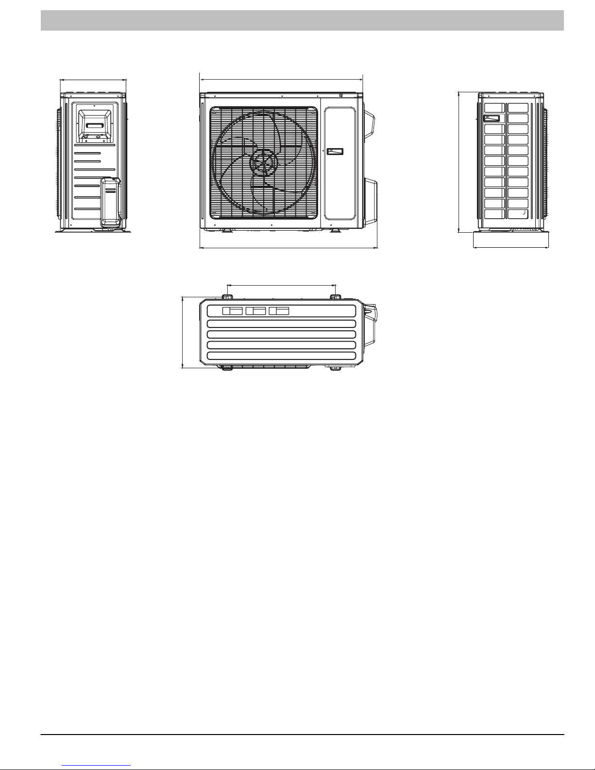
SERVICE MANUAL R−410A Ductless Split System: DLF4(A/H), DLC4(A/H)
13.4
(340.4)
15.6
(396.2)
in. (mm)
UNIT SIZE − 18
35
(889.0)
37.6
(955.0)
(Net Operating Weight: 99 lbs.- 45 kg.)
14.5
(368.3)
27.6
(701.0)
14.6
(368.3)
16.8
(426.7)
22
(558.8)
UNIT SIZE − 24
(914.4)
(980.4)
(Net Operating Weight: 121 lbs.- 55 kg.)
36
38.6
31.1
A12382
(789.9)
in. (mm)
20 421 08 9204 00
24
(609.6)
15.7
(398.8)
A12383
SERVICE MANUAL R−410A Ductless Split System: DLF4(A/H), DLC4(A/H)
UNIT SIZE − 30 (Net Operating Weight: 154 lbs − 70 kg.)
36 (Net Operating Weight: 161 lbs − 73 kg.)
14.6
(370.8)
36
(914.4)
(789.9)
31.1
in. (mm)
(398.8)
15.7
38.6
(980.4)
24
(609.6)
16.7
(424.2)
A12379
421 08 9204 00 21
SERVICE MANUAL R−410A Ductless Split System: DLF4(A/H), DLC4(A/H)
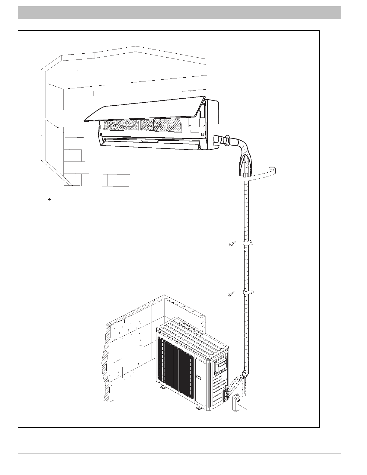
CLEARANCES
Indoor Unit
Distance to Ceiling
6” (152 mm)
Distance to Wall
6” (152 mm)
Clearance in front of unit
118” (2997 mm)
The clearance dimensions are necessary for a correct installation,
and are the minimum permissible distances to adjacent structures.
Distance to Floor
66” (1676 mm)
Distance to Wall
6” (152 mm)
NOTE: Refrigerant lines
may be routed in any of
the (4) directions, right,
right rear, left, or left rear.
See instructions for de
tails.
Outdoor Unit
Above Unit
20” (508 mm)
Distance to
Back Wall
12” (305 mm)
Air Discharge Side
79” (2007 mm)
Figure 2 - Unit clearance
Air Inlet Side
12” (305 mm)
Distance to Wall
20” (508 mm)
Valve Cover
A07891
22 421 08 9204 00
SERVICE MANUAL R−410A Ductless Split System: DLF4(A/H), DLC4(A/H)
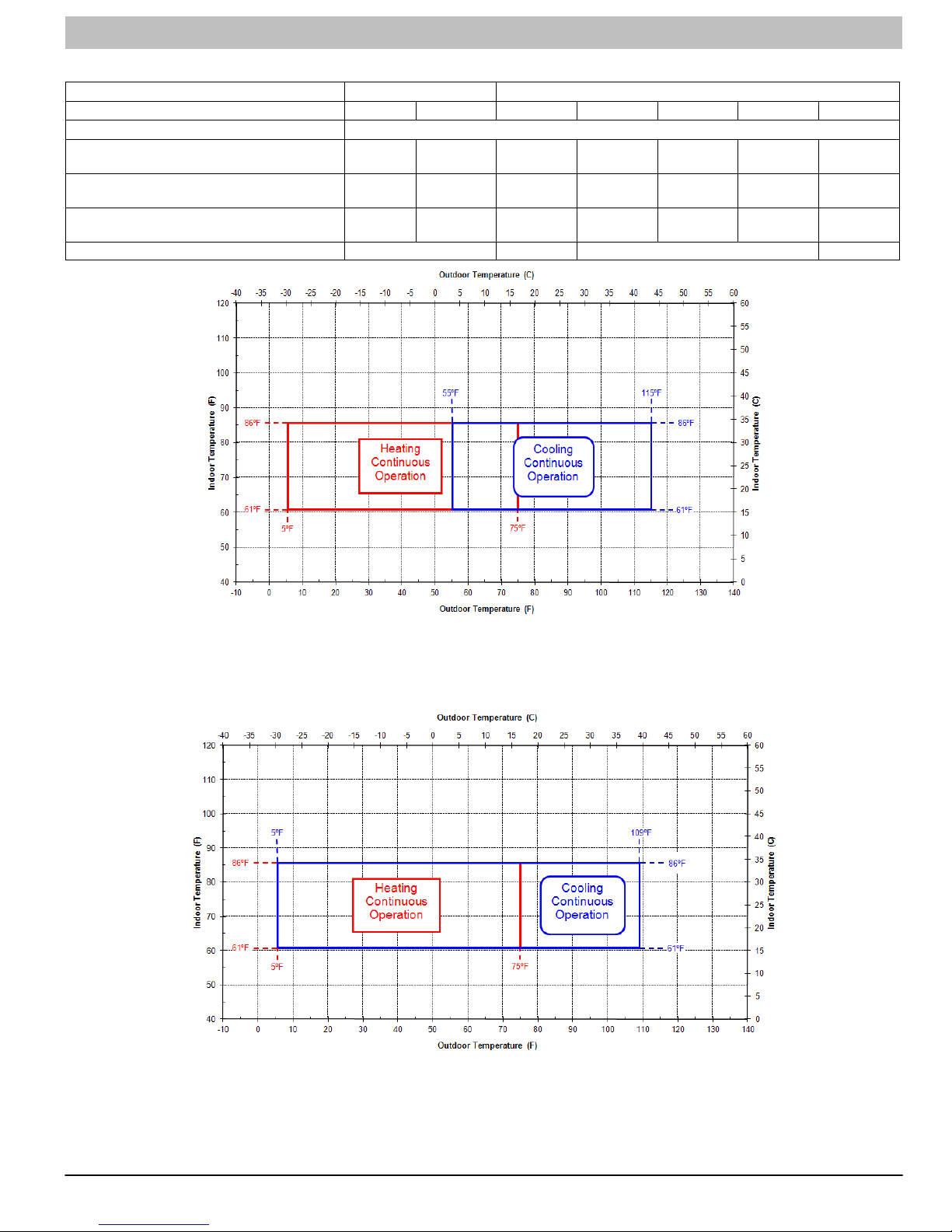
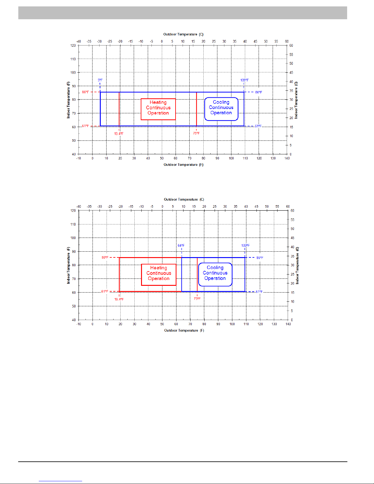
SYSTEM OPERATING ENVELOPES
Supply Voltage 115-1-60 AC 208/230-1-60 AC
Model Size 9k 12k 12k 18k 24k 30k 36k
Indoor Operating Range (A/C and HP) °F (°C) 61 - 86 (16 - 30)
Cooling Ambient Operating Range (A/C) °F (°C)
Cooling Ambient Operating Range (HP) °F (°C)
Heating Ambient Operating Range (HP) °F (°C)
Figure 3 4 5 6
55 - 115
(13 - 46)
55 - 115
(13 - 46)
5 - 75
(-15 - 24)
55 - 115
(13 - 46)
55 - 115
(13 - 46)
5 - 75
(-15 - 24)
5 - 109
(-15 - 43)
5 - 109
(-15 - 43)
5 - 75
(-15 - 24)
5 - 109
(-15 - 43)
5 - 109
(-15 - 43)
19.4 - 75
(-7 - 24)
5 - 109
(-15 - 43)
5 - 109
(-15 - 43)
19.4 - 75
(-7 - 24)
N/A 64 - 109
5 - 109
(-15 - 43)
19.4 - 75
(-7 - 24)
(18 - 43)
64 - 109
(18 - 43)
19.4 - 75
(-7 - 24)
Figure 3 - 9k / 12k 115V System Operating Envelopes
Figure 4 - 12k 230V System Operating Envelopes
421 08 9204 00 23
SERVICE MANUAL R−410A Ductless Split System: DLF4(A/H), DLC4(A/H)
SYSTEM OPERATING ENVELOPES (CONT.)
Figure 5 - 18k, 24k, and 30k 230V System Operating Envelopes
Figure 6 - 36k 230V System Operating Envelopes
24 421 08 9204 00
SERVICE MANUAL R−410A Ductless Split System: DLF4(A/H), DLC4(A/H)
ELECTRICAL DATA
Table 2 − Accessory Condensate Pump Kit Contents
Electrical Data Table
Operating
Unit
Size
9K 115 −1−60 103/127 16.03 33 0.17 0.054 30 115 V−AC 0.38 0.056 20 22 35
12K 115−1−60 103/127 17.53 33 0.17 0.058 30 115 V−AC 0.38 0.056 20 23 40
12K 208/230−1−60 187/253 6.47 13.8 0.14 0.058 30 208/230 V−AC 0.20 0.056 20 10 15
18K 208/230−1−60 187/253 9.70 13.8 0.32 0.156 60 208/230 V−AC 0.28 0.075 20 13 20
24K 208/230−1−60 187/253 11.04 18.5 1.10 0.224 90 176−375V−DC 0.24 0.068 60 16 25
30K 208/230−1−60 187/253 13.45 40 0.45 0.228 100 208/230 V−AC 0.40 0.106 40 20 30
36K−AC 208/230−1−60 187/253 16.92 67 0.73 0.268 170 208/230 V−AC 0.47 0.114 60 24 35
36K−HP 208/230−1−60 187/253 17.50 67 0.73 0.268 170 208/230 V−AC 0.47 0.114 60 24 40
LEGEND
FLA − Full Load Amps
LRA − Locked Rotor Amps
MCA − Minimum Circuit Amps
RLA − Rated Load Amps
MOCP − Maximum Over Current Protection
WIRING
The main power is supplied to the outdoor unit. The field
supplied connecting cable from the outdoor unit to indoor unit
consists of four wires and provides the power for the indoor unit
as well as the communication signal and ground between the
outdoor and indoor unit.
Two wires are high voltage AC power, one is low voltage DC
signal and one is a ground wire.
Consult local building codes, NEC (National Electrical Code) or
CEC (Canadian Electrical Code) for special requirements.
Voltage drop on the connecting cable should be kept to a
minimum. Use cable size and max length below:
EQUIPMENT DAMAGE HAZARD
Failure to follow this caution may result in equipment
damage or improper operation.
Use copper conductors only with a minimum 300 volt
rating and 2/64 inch thick insulation.
System Voltage
Volts−Ph.−Freq.
18 AWG 50 ft. (16m)
16 AWG 100 ft. (33m)
!
CAUTION
Voltage
(Min/Max)
Compressor Outdoor Fan Indoor Fan
Output
RLA LRA FLA HP
Watts Volts FLA HP
!
EQUIPMENT DAMAGE HAZARD
Failure to follow this caution may result in equipment
damage or improper operation.
Be sure to comply with local codes while running wire from
indoor unit to outdoor unit.
Every wire must be connected firmly. Loose wiring may
cause terminal to overheat or result in unit malfunction. A
fire hazard may also exist. Therefore, be sure all wiring is
tightly connected.
No wire should be allowed to touch refrigerant tubing,
compressor or any moving parts.
Disconnecting means must be provided and shall be
located within sight and readily accessible from the air
conditioner.
Connecting cable with conduit shall be routed through
hole in the conduit panel.
CAUTION
Output
Watts
MCA
Fuse/CB
Amps
(MOCP)
Max
421 08 9204 00 25
 Loading...