

ICP CHS180 Installation, Start-up And Service Instructions Manual

Installation, Start--Up, and
Service Instructions
Split System Heat Pump
Three Phase -- 208/230, 460 Volt
Save This Manual for Future Reference
Models
CHS180
506 01 2002 01
5/07/07
Split System Heat PumpsInstallation Instructions
Installation/ Startup
Information
!
FIRE, AND ELECTRICAL SHOCK HAZARD
Failure to follow this warning could result in personal
injury, death and/or property damage.
Before performing service or maintenance operations
on unit, turn off unit main power switch and install
lockout tag.
These instructions must be read and understood
completely before attempting installation.
WARNING
Installation or repairs made by unqualified
persons can result in hazards to you and others.
Installation MUST conform with local building
codes or, in the absence of local codes, with the
the National Electrical Code NFPA 70/ANSI
C1-1999 or current edition and Canadian
Electrical Code Part 1 CSA C.22.1.
The information contained in this manual is
intended for use by a qualified service technician
familiar with safety procedures and equipped
with the proper tools and test instruments.
Failure to carefully read and follow all instructions in this manual can result in equipment
malfunction, property damage, personal injury
and/or death.
After uncrating unit,inspect thoroughly for hidden damage.
If damage is found, notify the transportation company
immediately and file a concealed damage claim.
!
REDUCED EQUIPMENT LIFE AND PERSONAL INJURY
HAZARD
mproper installation, adjustment, alteration, service or
maintenance can void the warranty.
The weight of the condensing unit requires caution and
proper handling procedures when lifting or moving to
avoid personal injury. Use care to avoid contact with
sharp or pointed edges.
CAUTION
Safety Precautions
1. Always wear safety eye wear and work gloves when
installing equipment.
2. Never assume electrical power is disconnected. Check
with meter and disconnect.
3. Keep hands out of fan areas when power is connected
to equipment.
4. R--22 causes frost--bite burns.
5. R--22 is toxic when burned.
Locating The Outdoor Unit:
Check local codes covering zoning, noise, platforms.
If practical, avoid locating next to fresh air intakes, vent or
windows. Noise may carry into the openings and disturb
people inside.
Placement of the unit should be in a well drained area or
unit must be supported high enough so runoff will not enter
the unit.
Do not locate where heat, lint or exhaust fumes will be
discharged on unit (as from dryer vents).
Roof top installations are acceptable providing the roof will
support the unit and provisions are made for water
drainage and the noise or vibration through the structure.
Do not install the unit in a recessed or confined area where
recirculation of discharge air may occur.
Top skid assembly should be left in place until after the unit
is rigged into its final location.
2
Allow sufficient space for airflow clearance, wiring,
refrigerant piping, and servicing unit.
Split System Heat Pumps Installation Instructions
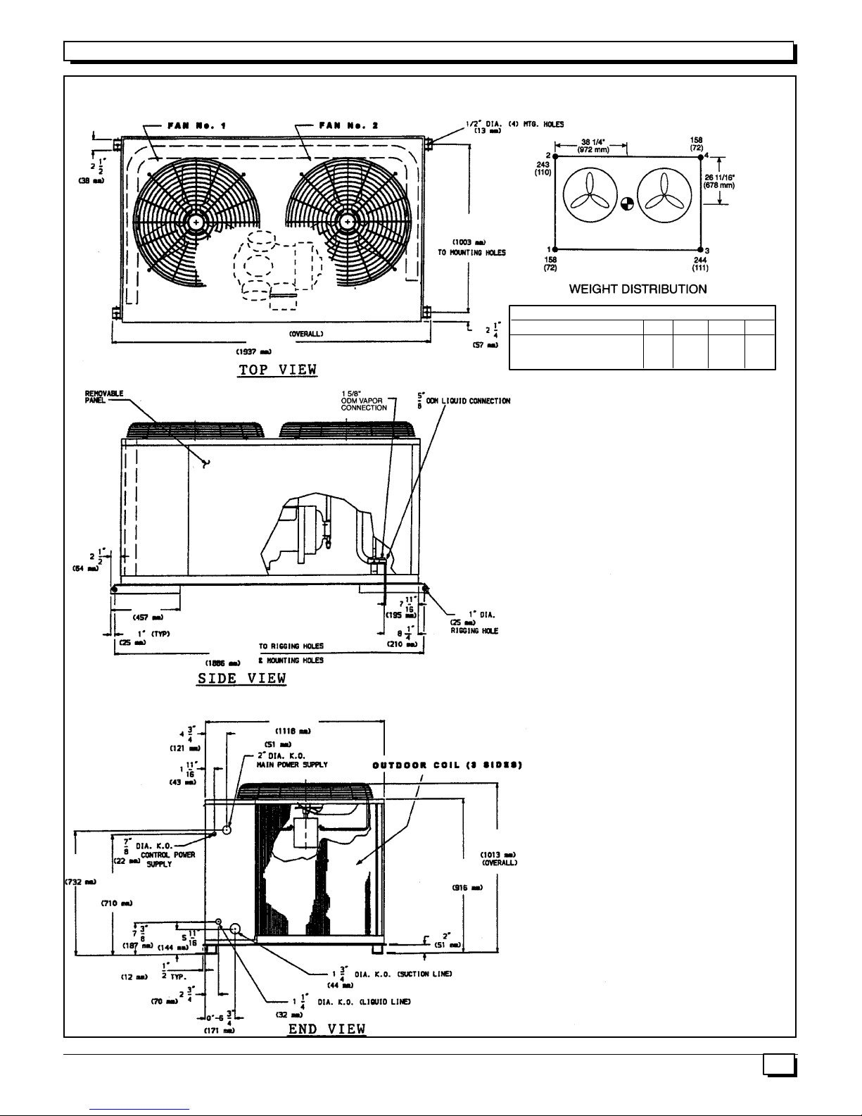
Figure 1
CHS180 UNIT DIMENSIONS and CLEARANCES
39--1/2”
76--1/2”
Unit Total Weight 1 2 3 4
CHS180 803 158 243 244 158
(365) (72) (110) (111 ) (72)
NOTE: Recommended service clearances are as follows
(local codes or jurisdictions may prevail):
Side (compressor) -- 3--1/2 ft. (1067 mm)
Side (opposidte compressor) -- 3 ft. (914 mm)
Ends -- 2 ft. (616 mm)
Top -- 5 ft. (1524 mm)
Support Point
28--13/16”
18”
74--1/4”
43”
39--7/8”
36--1/16”
27--15/16”
3
Split System Heat PumpsInstallation Instructions
Rig and Mount the Unit:
!
REDUCED EQUIPMENT LIFE HAZARD
Failure to follow these precautions could result in
damage to the unit being installed.
Be sure unit panels are securely in place prior to rigging.
RIGGING -- See Figure 2. These units are designed for
overhead rigging. Refer to rigging label for preferred
rigging method. Spreader bars are not required if top
crating is left on unit. All panels must be in place when
rigging. As further protection for coil faces, plywood sheets
may be placed against sides of unit, behind cables. Run
cables to a central suspension point so that angle from the
horizontal is not less than 45 degrees. Raise and set unit
down carefully.
If it is necessary to roll the unit into position, mount the unit
on field--supplied rails placed lengthwise under the unit
using a minimum of 3 rollers. Apply force to the rails, not the
unit. If the unit is to be skidded into position, place it on a
large pad and drag it by the pad. Do not apply any force to
the unit.
Raise from above to lift unit from the rails or pad when unit
is in final position.
After unit in position, remove all shipping materials and top
crating.
NOTE: Before mounting unit, remove holddown brackets
and release skid. If conditions or local c odes require unit to
be fastened to pad, use the mounting holes in the base
rails.
CAUTION
Clearances:
Locate unit so that outdoor coil (condenser) airflow is
unrestricted on all sides and above. See Figure 1 for unit
clearances, weight, and clearance data.
Unit Support:
The unit must be level, and supported above grade by
beams, platform or a pad. Platform or pad can be of open or
solid construction but should be of permanent materials
such as concrete, bricks, blocks, steel or pressure treated
timbers approved for ground contact. Refer to Unit
Clearances and weights to help determine size of supports
etc. Soil conditions should be considered so the platform or
pad does not shift or settle excessively and leave the unit
only partially supported.
!
REDUCED EQUIPMENT LIFE HAZARD
Failure to follow these precautions could result in
damage to the unit being installed.
Inadequate support could cause excessive vibration
and noise or binding and stress on refrigerant lines
resulting in equipment failure.
To minimize vibration or noise transmission, it is
recommended that supports not be in contact with the
building structure. However, slabs on grade constructions with an extended pad are normally acceptable.
A. Ground Level Installation:
If beams or an open platform are used for support it is
recommended that the soil be treated or area be graveled
to retard the growth of grasses and weeds.
B. Roof Top Installation:
This type of installation is not recommended on wood
frame structures where low noise levels are required.
Supporting structure or platform for the unit must be level. If
installation is on a flat roof the unit should be 4 inches
(10cm.) above roof level. Four by four posts placed over a
load bearing wall make a suitable mounting platform.
If possible, place the unit over one or more load bearing
walls. If there are several units, mount them on platforms
that are self--supporting and span load bearing walls.
These suggestions are to minimize noise and vibration
transmission through the structure.
CAUTION
4
Split System Heat Pumps Installation Instructions
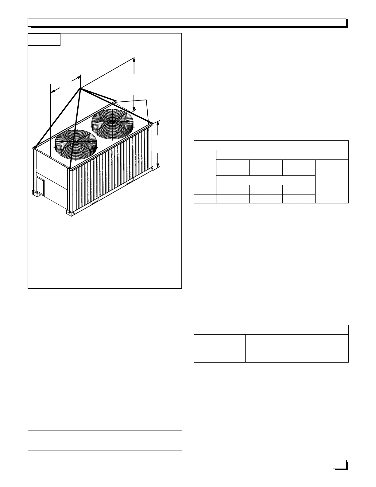
Figure 2
NOTICE TO RIGGERS
All Panels Must Be In Place When
Rigging
3’ 7”
1092mm
10’ 0”
3048mm
Spreader
Bars
10’ 0”
3048mm
NOTICE TO RIGGERS: Rig by inseting hooks into unit
base rails as shown. Maintain a distance of 120 inches (3048mm) from top of unit to eyehook. Use corner
post or top board from packaging to protect coil of unit
from damage by rigging cable. Use bumper boards for
spreader bars.
CHECK VERTICAL SEPARATION -- If there is any vertical
separation between the indoor and outdoor units, check to
ensure that the separation is within allowable limits.
Relocate equipment if necessary. See Table 2.
SIZE REFRIGERANT LINES -- Consider the length of the
piping required between the outdoor and indoor units. The
maximum allowable line length is 100 ft (30.5 m). See Table
1. Refrigerant suction piping should be insulated.
Carefully evaluate any vapor risers at minimum load
conditions to ensure proper compressor oil return. If the
indoor unit is above the outdoor unit, the riser will function
as a hot gas riser. If the outdoor unit is above the indoor
unit, the riser is a suction riser. Use a reduced diameter
riser design and construct a double riser if necessary.
Table 1 - Refrigerant Piping Sizes
Linear Length of Interconnecting Piping -- Ft. (mm)
0--25
(0 -- 7.5)
Unit
CHS180 5/8 1--5/8 3/4 1--5/8 3/4 1--5/8
L S L S L S 3/4
25 -- 60
(7.5 -- 18)
Line Size (in. OD)
61 -- 100
(18.3 -- 30 )
Maximum
Liquid Line
LEGEND
L -- Liquid Line, S -- Suction Line
*Maximum length of interconnecting pipe is 100 ft (30.5 m).
NOTES:
1. Pipe sizes are based on a 2° F(1° C) loss for liquid
and suction lines.
2. Pipe sizes are based on the maximum linear length,
shown for each column, plus a 50% allowance for
fittings.
Installing Refrigerant Lines
Complete Refrigerant Piping
Connections
Refrigerant lines must be carefully designed and
constructed to ensure equipment reliability and efficiency.
Line length, pressure drop, compressor oil return, and
vertical separation are several of the design criteria that
must be evaluated. See Table 1.
IMPORTANT: Piping must be properly sized and
installed for the system to operate efficiently.
3. Charge units with R--22 in accordance with unit
installation instructions.
4. Maximum line length must not exceed 100 ft
(30.5 m).
Table 2 - Max. Vertical Separation Between Indoor & Outdoor Units
Unit Evap. Distance ft (m)
Unit
CHS180 BHC180 80 (24.4)
Above Unit Evap.
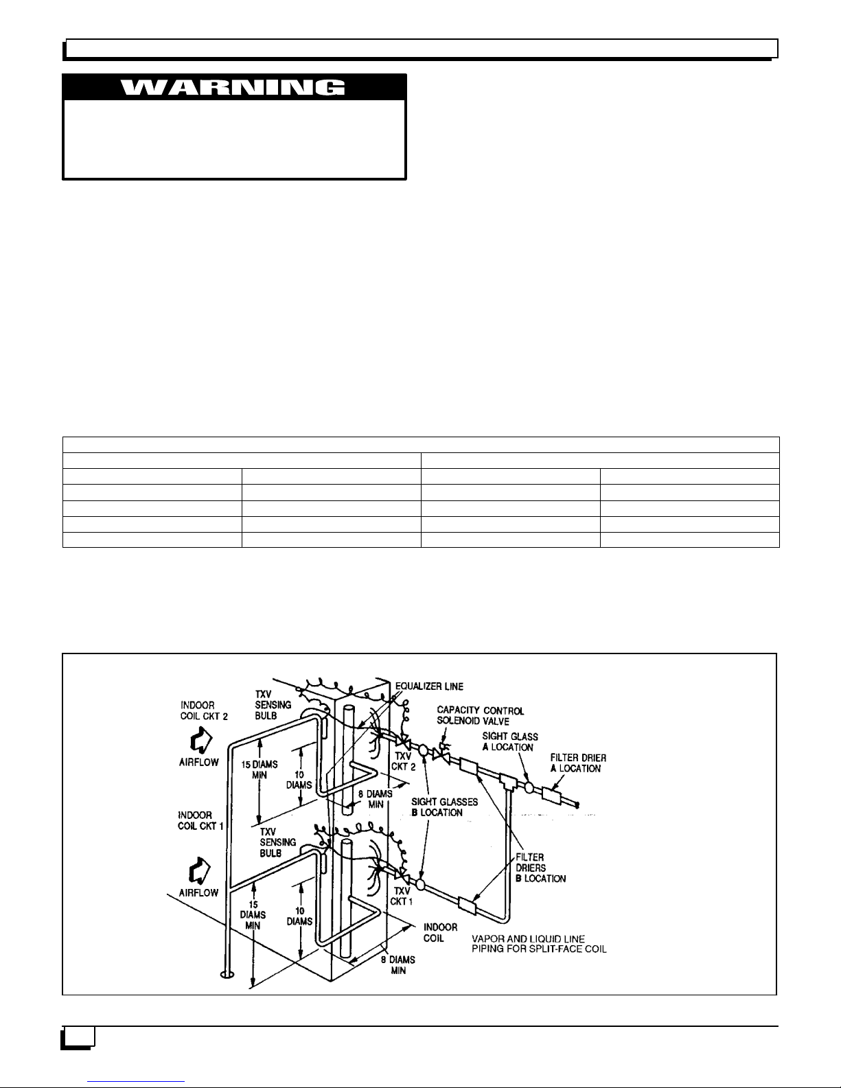
INSTALL FILTER DRIER(S) AND MOISTURE
INDICATOR(S) -- Every unit should have a filter drier and
liquid--moisture indicator (sight glass). In some
applications, depending on space and convenience
requirements, it may be desirable to install 2 filter driers
and sight glasses. One filter drier and sight glass may be
installed at A locations in Fig. 3. Or, 2 filter driers and sight
glasses may be installed at B locations.
Select the filter drier for maximum unit capacity and
minimum pressure drop. Complete the refrigerant piping
from indoor unit to outdoor unit before opening the liquid
and suction lines at the outdoor unit.
5
Split System Heat PumpsInstallation Instructions
WARNING
Recover R--22 holding charge before removing
runaround liquid piping loop. Failure to recover
holding charge before removing piping loop
could result in equipment damage and severe
injury.
MAKE PIPING CONNECTIONS
1. Open service valves in sequence:
a. Discharge service valve on compressor.
b. Suction service valve on compressor.
c. Liquid line valve.
2. Remove 1/4 --in. flare cap from liquid valve Schrader
port.
3. Attach refrigerant recovery device and recover
holding charge.
4. Remove runaround loop.
Table 3 -- Insulation for Vapor Line Exposed to Outdoor Conditions
Length of Exposed Vapor Line* Insulation Thickness
feet meter inches mm
10 3 3/8 10
25 8 1/2 13
35 11 3/4 19
50 15 3/4 19
5. Connect system liquid line from liquid connection of
outdoor unit(CHS) to indoor unit liquid line
connections. Select proper field-- supplied bi--flow
filter driers and install in the liquid line. See Fig. 2.
Install a field--supplied liquid moisture indicator
between the filter drier(s) and the liquid c onnections
on the indoor unit. Braze or silver alloy solder all
connections.
Pass nitrogen or other inert gas through piping while
making connections to prevent formation of copper oxide.
(Copper oxides are extremely active under high
temperature and pressure. Failure to prevent collection of
copper oxides may result in system component failures.)
VAPOR LINE PIPING PROCEDURE -- Connect system
vapor line to the vapor line stub on the outdoor unit and the
vapor stubs on the indoor unit. At the indoor unit, construct
vapor piping branches as shown in Fig. 3 for good mixing of
the refrigerant leaving the indoor coil during cooling. This
will ensure proper TXV (thermostatic expansion valve)
bulb sensing. Where vapor line is exposed to outdoor air,
line must be insulated. See Table 3 for insulation
requirements.
*Recommended vapor line insulation for piping exposed to outdoor conditions to prevent loss of heating during heating
cycle. When vapor line goes through interior spaces, insulation should be selected to prevent condensation on cooling
cycle. Heating capacity should be reduced 1000 Btuh (295 W) if over 35 ft (11m) of vapor line with 3/4 in. (19 mm) insulation
is exposed to outdoor conditions.
+Closed cell foam insulation with a thermal conductivity of: 0.28 Btu • in./ft 2 • h •°F (0.04W/m •°C).
Fig. 3 — Location of Sight Glass(es) and Filter Driers (Typical)
6
LEGEND
TXV -- Thermostatic Expansion Valve
 Loading...