

Printed in U.S.A. 441 01 2314 06 July 2010
INSTALLATION INSTRUCTIONS
80% Single Stage, Downflow,
Category I, Gas Furnace
C8DNL, H8DNL, T8DNL
These instructions must be read and understood completely before attempting installation.
Safety Labeling and Signal Words
DANGER, WARNING, CAUTION, and NOTE
The signal words DANGER, WARNING,
CAUTION, and NOTE are used to identify levels of
hazard seriousness. The signal word DANGER is
only used on product labels to signify an immediate
hazard. The signal words WARNING, CAUTION,
and NOTE will be used on product labels and
throughout this manual and other manual that may
apply to the product.
DANGER − Immediate hazards which will result in
severe personal injury or death.
WARNING − Hazards or unsafe practices which
could result in severe personal injury or death.
CAUTION − Hazards or unsafe practices which
may result in minor personal injury or product or
property damage.
NOTE − Used to highlight suggestions which will
result in enhanced installation, reliability, or
operation.
!
WARNING
Signal Words in Manuals
The signal word CAUTION is used throughout
this manual in the following manner:
!
CAUTION
Signal Words on Product Labeling
Signal words are used in combination with
colors and/or pictures or product labels.
The signal word WARNING is used throughout
this manual in the following manner:
Safety−alert symbol
When you see this symbol on the unit and in
instructions or manuals, be alert to the
potential for personal injury.
TABLE OF CONTENTS
SAFETY CONSIDERATIONS 2...................
Safe Installation Requirements 3..................
INSTALLATION 4...............................
Combustion & Ventilation Air 6....................
Gas Vent Installation 9...........................
Venting (Horizonta) 10............................
Venting (Chimney Adapter) 12.....................
Gas Supply and Piping 15.........................
Electrical Wiring 17...............................
Ductwork and Filter 18............................
Checks and Adjustments 23.......................
Furnace Maintenance 27..........................
Sequence of Operation & Diagnostics (*8DNL) 28....
Wiring Diagram (*8DNL) 32.......................
International Comfort Products, LLC
Lewisburg, TN 37091 U.S.A.
!
WARNING
PERSONAL INJURY, AND/OR PROPERTY
DAMAGE HAZARD
Failure to carefully read and follow this warning could
result in equipment malfunction, property damage,
personal injury and/or death.
Installation or repairs made by unqualified persons
could result in equipment malfunction, property
damage, personal injury and/or death.
The information contained in this manual is intended for
use by a qualified service technician familiar with safety
procedures and equipped with proper tools and test
instruments.
Installation must conform with local building codes and
with the Natural Fuel Gas Code (NFCG) NFPA 54/ANSI
Z223.1, and National standards of Canada
CAN/CSA−B149.1 and .2 Natural Gas and Propane
Installation Codes.
INSTALLER: Affix these instructions on or adjacent to the
furnace.
CONSUMER: Retain these instructions for future reference.
Portions of the text and tables are reprinted from NFPA 54 /ANSI Z223.1−2009©, with permission of National Fire Protection Association, Quincy, MA 02269 and American Gas Association, Washington,
DC 20001. This reprinted material is not the complete and official position of the NFPA or ANSI, on the referenced subject, which is represented only by the standard in its entirety.
441 01 2314 06
Specifications are subject to change without notice
2
SAFETY CONSIDERATIONS
Improper installation, adjustment, alteration, service,
maintenance, or use can cause explosion, fire, electrical
shock, or other conditions which may cause death, personal
injury, or property damage. Consult a qualified installer,
service agency, or your distributor or branch for information or
assistance. The qualified installer or agency must use
factory−authorized kits or accessories when modifying this
product. Refer to the individual instructions packaged with the
kits or accessories when installing.
Follow all safety codes. Wear safety glasses, protective
clothing, and work gloves. Use quenching cloth for
brazing operations. Have fire extinguisher available.
Read these instructions thoroughly and follow all
warnings or cautions included in literature and attached
to the unit. Consult local building codes, the current
editions of the National Fuel Gas Code (NFCG) NFPA
54/ANSI Z223.1, and the National Electrical Code
(NEC) NFPA 70.
In Canada refer to the current editions of the National
standards of Canada CAN/CSA−B149.1 and .2 Natural
Gas and Propane Installation Codes, and Canadian
Electrical Code CSA C22.1.
Recognize safety information. This is the safety−alert
symbol
. When you see this symbol on the unit and
in instructions or manuals, be alert to the potential for
personal injury. Understand these signal words;
DANGER, WARNING, and CAUTION. These words are
used with the safety−alert symbol. DANGER identifies
the most serious hazards which will result in severe
personal injury or death. WARNING signifies hazards
which could result in personal injury or death.
CAUTION is used to identify unsafe practices which
may result in minor personal injury or product and
property damage. NOTE is used to highlight
suggestions which will result in enhanced installation,
reliability, or operation.
ELECTRICAL SHOCK HAZARD
Failure to follow this warning could cause personal
injury or death.
Before performing service or maintenance operations
on unit, always turn off main power switch to unit and
install lockout tag. Unit may have more than one
power switch.
!
WARNING
CARBON MONOXIDE POISONING AND FIRE
HAZARD
Failure to follow safety warnings could result in
personal injury, death, and/or property damage.
This furnace is not designed for use in mobile
homes, trailers or recreational vehicles.
!
WARNING
CUT HAZARD
Failure to follow this caution may result in damage
personal injury.
Sheet metal parts may have sharp edges or burrs.
Use care and wear appropriate protective clothing,
safety glasses and gloves when handling parts and
servicing furnaces.
CAUTION
!
441 01 2314 06
Specifications are subject to change without notice.
2
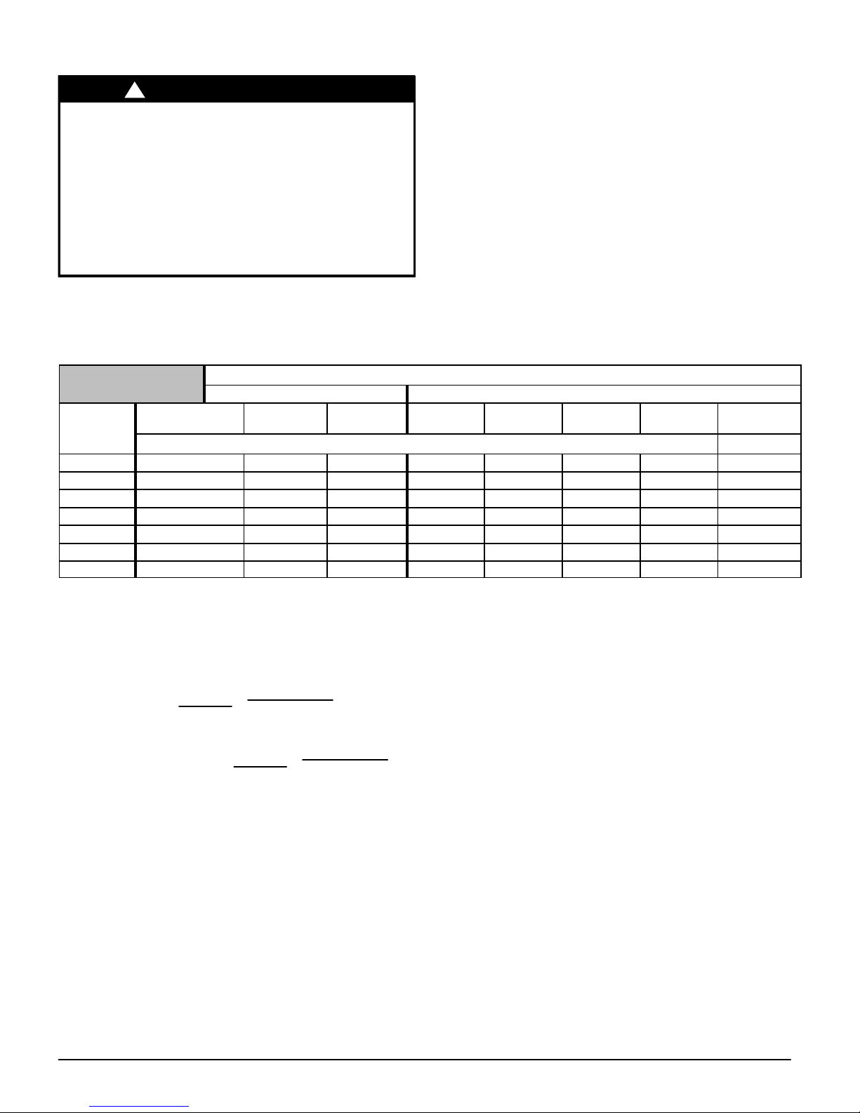
START−UP CHECK SHEET
For 80+ Furnace
(This sheet is optional. Keep this page for future reference.)
Date of Start−Up:
Dealer Name:
Address:
City, State(Province), Zip or Postal Code:
Phone:
Owner Name:
Address:
City, State(Province), Zip or Postal Code:
Model Number:
Serial Number:
Setup Checks
Check the box when task is complete
Thermostat: Heat
Cooling Fan
Subbase level:
Anticipator Set: Setting of Anticipator ____
All Electrical Connections Tight:
Supply voltage: ____
Blower Motor H.P.: ____
Fan “Time ON” setting: ____ Fan “Time OFF” Setting ___
Manual Gas Shut−Off Upstream of Furnace/Drip−Leg?
Gas Valve turned ON?
Type of Gas: Natural: Propane:
Filter Type and Size:
Calculated Firing Rate:(See Checks and Adjustments Sec-
tion).
Heating Check
Measured Line Pressure when Firing Unit:
Measured Manifold Gas Pressure:
Temperature of Supply Air: (°)
Temperature of Return Air: (°)
Temperature Rise (supply−return temperature): (°)
In Rise (see furnace rating plate)? (°)
Static Pressure (Ducts): Supply Air Return
Blower speed tap used for heating
Limit Opens: (°) Limit Closes: (°)
Optional Check: CO ? CO2 ?
Cooling Check
Temperature of Supply Air: (°)
Temperature of Return Air: (°)
Temperature Difference: (°)
Static Pressure (Ducts) cooling: Supply Air Return
Blower Speed Tap used for cooling: _______
Dealer Comments:
441 01 2314 06
Specifications are subject to change without notice.
3
1. Safe Installation Requirements
FIRE, EXPLOSION, AND ASPHYXIATING HAZARD
Improper adjustment, alteration, service,
maintenance or installation could cause death,
personal injury, and/or property damage.
Installation or repairs made by unqualified
persons could result in hazards to you and others.
Installation MUST conform with local codes or, in
the absence of local codes, with codes of all
governmental authorities having jurisdiction.
The information contained in this manual is
intended for use by a qualified service agency that
is experienced in such work, is familiar with all
precautions and safety procedures required in
such work, and is equipped with the proper tools
and test instruments.
!
WARNING
NOTE: This furnace is design−certified by CSA International (for-
merly AGA and CGA) for installation in the United States and Canada. Refer to the appropriate codes, along with this manual, for
proper installation.
• Use only the Type of gas approved for this furnace (see Rat-
ing Plate on unit). Overfiring will result in failure of heat ex-
changer and cause dangerous operation. (Furnaces can be
converted to Propane gas with approved kit.)
• Install this furnace only in a location and position as speci-
fied in “Installation” of these instructions.
• Provide adequate combustion and ventilation air to the fur-
nace as specified in “Combustion and Ventilation Air” of
these instructions.
• Combustion products must be discharged outdoors. Con-
nect this furnace to an approved vent system only, as specified in “Gas Vent Installation, Horizontal Venting and
Masonry Chimney Venting” of these instructions.
• Never test for gas leaks with an open flame. Use a commer-
cially available soap solution made specifically for the detection of leaks to check all connections, as specified in “Gas
Supply and Piping, Final Check” of these instructions.
• Always install furnace to operate within the furnace’s in-
tended temperature−rise range with a duct system which
has an external static pressure within the allowable range,
as specified in “Technical Support Manual” of these instructions. See furnace rating plate.
• When a furnace is installed so that supply ducts carry air cir-
culated by the furnace to areas outside the space containing
the furnace, the return air shall also be handled by a duct(s)
sealed to the furnace casing and terminating outside the
space containing the furnace.
• A gas−fired furnace for installation in a residential garage
must be installed as specified in “Installation” of these instructions.
• This furnace is not to be used for temporary heating of build-
ings or structures under construction. See “ Installation”
• This furnace is NOT approved for installation in mobile
homes, trailers or recreation vehicles.
• Seal around supply and return air ducts.
• Install correct filter type and size.
• Unit MUST be installed so electrical components are pro-
tected from direct contact with water.
Safety Rules
Your unit is built to provide many years of safe and dependable
service providing it is properly installed and maintained. However,
abuse and/or improper use can shorten the life of the unit and
create hazards for you, the owner.
A. The U.S. Consumer Product Safety Commission encourages
installation of carbon monoxide alarms. There can be various
sources of carbon monoxide in a building or dwelling. The
sources could be gas−fired clothes dryers, gas cooking
stoves, water heaters, furnaces, gas−fired fireplaces, wood
fireplaces.
Carbon monoxide can cause bodily injury and/or death. Carbon monoxide or “CO” is a colorless and odorless gas produced when fuel is not burned completely or when the flame
does not receive sufficient oxygen.
Therefore, to help alert people of potentially dangerous carbon
monoxide levels, you should have a commercially available
carbon monoxide alarm that is listed by a nationally recognized testing agency in accordance with Underwriters Laboratories Inc. Standard for Single and Multiple Station Carbon
Monoxide Alarms, ANSI/UL 2034 or the CSA 6.19−01 Residential Carbon Alarming Devices installed and maintained in
the building or dwelling concurrently with the gas−fired furnace
installation (see Note below). The alarm should be installed as
recommended by the alarm manufacturer’s installation instructions.
B. There can be numerous sources of fire or smoke in a building
or dwelling. Fire or smoke can cause bodily injury, death, and/
or property damage. Therefore, in order to alert people of potentially dangerous fire or smoke, you should have fire
extinguisher and smoke alarms listed by Underwriters Laboratories installed and maintained in the building or dwelling (see
Note below).
Note: The manufacturer of your furnace does not test any alarms
and makes no representations regarding any brand or type
of alarms.
C. To ensure safe and efficient operation of your unit, you should
do the following:
1. Thoroughly read this manual and labels on the unit. This
will help you understand how your unit operates and the hazards involved with gas and electricity.
2. Do not use this unit if any part has been under water. Immediately call a qualified service agency to inspect the unit and
to replace any part of the control system and any gas control
which has been under water.
3. Never obstruct the vent grilles, or any ducts that provide
air to the unit. Air must be provided for proper combustion and
ventilation of flue gases.
Frozen Water Pipe Hazard
WATER DAMAGE TO PROPERTY HAZARD
Failure to follow this warning could result in
property damage.
Do not leave your home unattended for long
periods during freezing weather without turning off
water supply and draining water pipes or otherwise
protecting against the risk of frozen pipes and
resultant damage.
!
WARNING
441 01 2314 06
Specifications are subject to change without notice.
4
Your furnace is designed solely to provide a safe and comfortable
living environment. The furnace is NOT designed to ensure that
water pipes will not freeze. It is equipped with several safety devices that are designed to turn the furnace off and prevent it from
restarting in the event of various potentially unsafe conditions.
If your furnace remains off for an extended time, the pipes in your
home could freeze and burst, resulting in water damage.
If the structure will be unattended during cold weather you should
take these precautions.
1. Turn off the water supply to the structure and drain the water
lines if possible and add an antifreeze for potable water to
drain traps and toilet tanks. Open faucets in appropriate
areas.
−or−
2. Have someone check the structure frequently during cold
weather to make sure it is warm enough to prevent pipes
from freezing. Instruct them on a service agency to call to
provide service, if required.
−or−
3. Install a reliable remote sensing device that will notify somebody of freezing conditions within the home.
2. Installation
CARBON MONOXIDE POISONING HAZARD
Failure to follow this warning could result in
personal injury or death.
If this furnace is replacing a previously common-
vented furnace, it may be necessary to resize the
existing vent system to prevent oversizing problems for the other remaining appliances(s). See
Venting and Combustion Air Check in the Gas Vent
Installation section of this instruction.
!
WARNING
Location and Clearances
If furnace is a replacement, it is usually best to install the furnace
where the old one was. Choose the location or evaluate the existing location based upon the minimum clearance and furnace dimensions (Figure 1).
CARBON MONOXIDE POISONING HAZARD
Failure to follow this warning could result in
personal injury or death.
Do NOT operate furnace in a corrosive
atmosphere containing chlorine, fluorine or any
other damaging chemicals, which could shorten
furnace life.
Refer to Combustion & Ventilation Air section,
Contaminated Combustion Air for combustion air
evaluation and remedy.
!
WARNING
Installation Requirements
1. Install furnace level.
2. This furnace is NOT to be used for temporary heat of buildings
or structures under construction.
3. Install furnace as centralized as practical with respect to the
heat distribution system.
4. Install the vent pipes as short as practical. (See Gas Vent
Installation section).
5. Do NOT install furnace directly on carpeting, tile or other combustible material. See Ductwork and Filter Sub−base for Combustible Floors.
6. Maintain clearance for fire safety and servicing. A front clearance of 24″ (609.6mm) required and 30″ (762mm) recommen-
ded for access to the burner, controls and filter. See clearance
requirements in Figure 1.
7. Use a raised base if the floor is damp or wet at times.
8. Residential garage installations require:
• Burners and ignition sources installed at least 18″ above
the floor.
• Furnace must be located or physically protected from
possible damage by a vehicle.
9. If the furnace is to be suspended from the floor joists in a basement or a crawl space or the rafters in an attic, it is necessary to
use steel pipe straps or an angle iron frame to attach the furnace. These straps should be attached to the furnace bottom
side with sheet metal screws and to the rafters or joists with
bolts. The preferred method is to use an angle iron frame
bolted to the rafters or joists.
10. This furnace may be used for construction heat provided that:
• The furnace is permanently installed with all electrical wir-
ing, piping, venting and ducting installed according to
these installation instructions. A return air duct is provided,
sealed to the furnace casing, and terminated outside the
space containing the furnace. This prevents a negative
pressure condition as created by the circulating air blower,
causing a flame rollout and/or drawing combustion products into the structure.
• The furnace is controlled by a thermostat. It may not be
“hot wired” to provide heat continuously to the structure
without thermostatic control.
• Clean outside air is provided for combustion. This is to
minimize the corrosive effects of adhesives, sealers and
other construction materials. It also prevents the entrainment of drywall dust into combustion air, which can cause
fouling and plugging of furnace components.
• The temperature of the return air to the furnace is main-
tained between 55° F (13° C) and 80° F (27° C) , with no
evening setback or shutdown. The use of the furnace
while the structure is under construction is deemed to be
intermittent operation per our installation instructions.
• The air temperature rise is within the rated rise range on
the furnace rating plate, and the firing rate has been set to
the rating plate value.
• The filters used to clean the circulating air during the
construction process must be either changed or thoroughly cleaned prior to occupancy.
• The furnace, ductwork and filters are cleaned as neces-
sary to remove drywall dust and construction debris from
all HVAC system components after construction is completed.
• Verify proper furnace operating conditions including igni-
tion, gas input rate, air temperature rise, and venting according to these installation instructions.
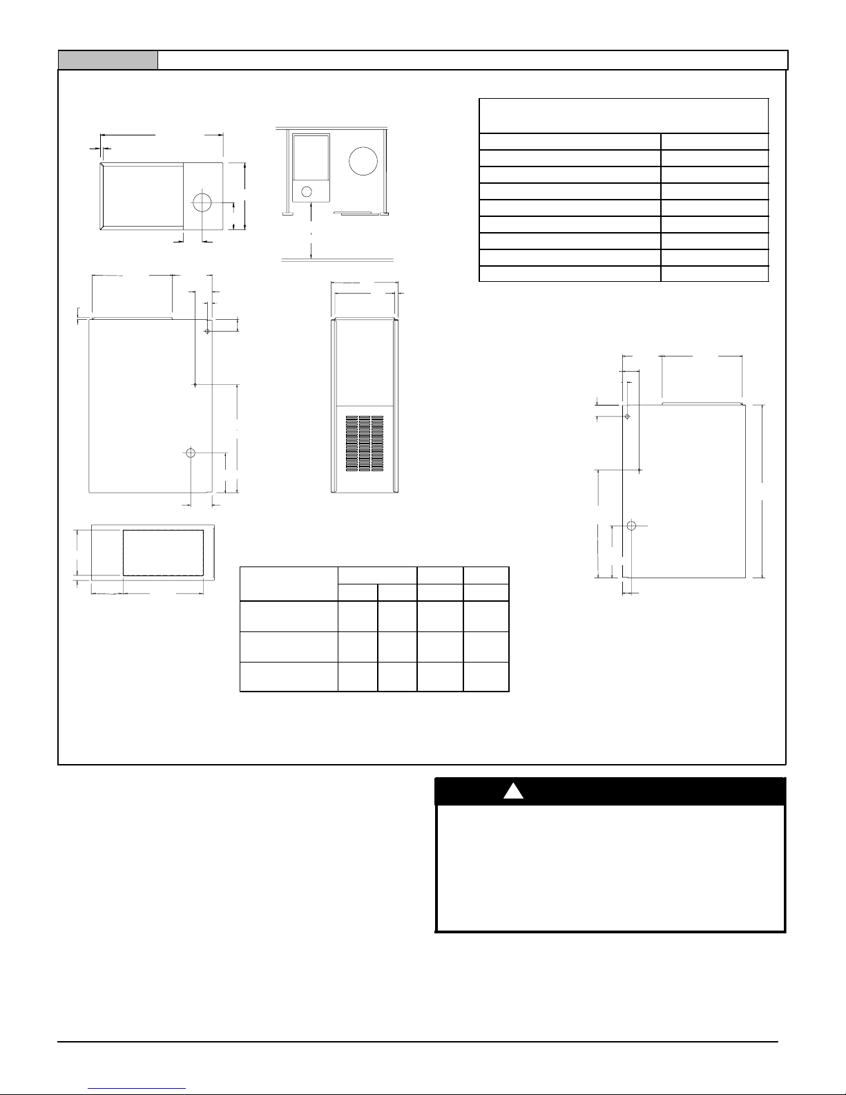
23/
16
37/
8
415/
16
ALL DIMENSIONS in(mm)
1 in = 25.4 mm
Drawing is representative, some models may vary in appearance
NOTE: Evaporator “A” coil drain pan dimensions
may vary from furnace duct opening size. Always
consult evaporator specifications for duct size
requirements.
Unit is designed for top return ONLY.
Return air through back of unit is NOT allowed.
TOP
water
heater
25−24−15a−1
30″
165/
8
11
/
16
81/
4
BOTTOM
D
LEFT SIDE
2415/
16
91/
8
181/
2
93/
16
213/
16
11/
16
3
/
4
FRONT
11
/
16
A
B
RIGHT SIDE
181/
2
37/
8
11/
16
93/
16
2415/
16
121/
16
33/
4
40
A
281/
2
313/
16
C
11
/
16
(724)
(470)
(762)
(17)
(97)
(19)
(27)
(232)
(633)
(71)
(98)
(233)
(125)
(17)
(210)
(422)
(95)
(306)
(633)
(267)
(1016)
(27)
(56)
(233)
(17)
(98)
441 01 2314 06
Specifications are subject to change without notice.
5
Figure 1 UNIT Dimensions and Clearances (*8DNL)DIMENSIONS
MINIMUM CLEARANCES TO COMBUSTIBLE
MATERIALS FOR ALL UNITS
REAR 0
FRONT 3″ (76 mm)
Recommended For Service 30″ (762 mm)
ALL SIDES Of SUPPLY PLENUM 1″ (25 mm)
SIDES 0
VENT
Single Wall Vent 6″ (152 mm)
Type B−1 Double Wall Vent 1″ (25 mm)
TOP OF FURNACE 1″ (25 mm)
Horizontal position: Line contact is permissible only between lines
formed by intersections of top and two sides of furnace jacket, and
building joists, studs or framing.
DIMENSIONAL INFORMATION
Unit
Capacity
Cabinet Top Bottom
A B C D
*8DNL050B12
*8DNL075B12
15 1/
2
(394)
14
(356)
55/
16
(135)
14 1/
8
(359)
*8DNL075F16
*8DNL100F14
19 1/
8
(486)
17 5/
8
(447)
7 3/
4
(197)
17 11/
16
(449)
*8DNL100L20
*8DNL125L20
24
1
/
2
(622)
23
(584)
10 7/
16
(265)
23 1/
8
(587)
* Denotes Brand
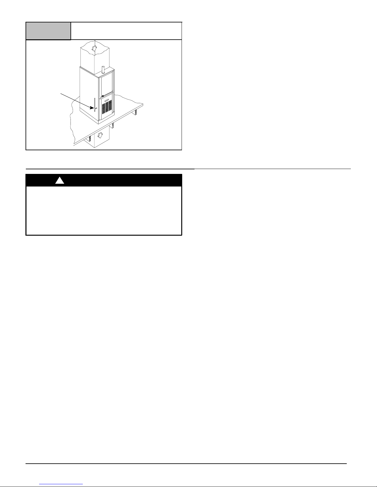
Furnace Installation
Inspect the rating plate to be certain the model number begins with
“*8DNL”. This identifies the furnace as a dedicated downflow furnace that is permitted to be Installed in a Downflow position. (see
Figure 2).
* Denotes Brand
Downflow
The minimum clearances to combustible material MUST be maintained between the furnace and adjacent construction, as shown
in Figure 1.
FIRE HAZARD
Failure to follow this warning could result in
personal injury, death and/or property damage.
Place furnace on noncombustible subbase on
downflow applications, unless installing on
noncombustible flooring.
!
WARNING
In addition to clearances in Figure 1, clearance for the vent pipe
must be considered.
A subbase for combustible floors MUST be used when the furnace
is installed on combustible material. See “Ductwork and Filter”.
441 01 2314 06
Specifications are subject to change without notice.
6
Typical Downflow Installation
Figure 2
VENT
GAS SUPPLY
SUPPLY
AIR
RETURN
AIR
25−24−38
3. Combustion & Ventilation Air
CARBON MONOXIDE POISONING HAZARD
Failure to follow this warning could result in
personal injury or death.
Use methods described here to provide
combustion and ventilation air.
!
WARNING
Furnaces require ventilation openings to provide sufficient air for
proper combustion and ventilation of flue gases. All duct or openings for supplying combustion and ventilation air must comply with
the gas codes, or in the absence of local codes, the applicable national codes.
Combustion and ventilation air must be supplied in accordance
with one of the following:
Note: The Combustion & Ventilation Air Section in this document,
uses tables and information from the ANSI Z223.1/NFPA
54. For use in Canada, use CSA B149.1 for this
information.
1. Section 9.3, Air for Combustion and Ventilation, of the National
Fuel Gas Code, (NFGC), ANSI Z223.1/NFPA 54−2009 in the
U.S.,
2. Sections 8.2, 8.3, 8.5, 8.6, 8.7, and 8.8 of National Standard of
Canada, Natural Gas and Propane Installation Code
(NSCNGPIC), CSA B149.1−05 in Canada,
3. Applicable provisions of the local building code.
When the installation is complete, check that all appliances have
adequate combustion air and are venting properly. See Venting
And Combustion Air Check in “Gas Vent Installation” Section in
this manual.
Contaminated Combustion Air
Installations in certain areas or types of structures could cause excessive exposure to contaminated air having chemicals or halogens that will result in safety and performance related problems
and may harm the furnace. These instances must use only outdoor air for combustion.
The following areas or types of structures may contain or have exposure to the substances listed below. The installation must be
evaluated carefully as it may be necessary to provide outdoor air
for combustion.
• Commercial buildings.
• Buildings with indoor pools.
• Furnaces installed in laundry rooms.
• Furnaces installed in hobby or craft rooms.
• Furnaces installed near chemical storage areas.
• Permanent wave solutions for hair.
• Chlorinated waxes and cleaners.
• Chlorine based swimming pool chemicals.
• Water softening chemicals.
• De−icing salts or chemicals.
• Carbon tetrachloride.
• Halogen type refrigerants.
• Cleaning solvents (such as perchloroethylene).
• Printing inks, paint removers, varnishes, etc.
• Hydrochloric acid.
• Sulfuric Acid.
• Solvent cements and glues.
• Antistatic fabric softeners for clothes dryers.
• Masonry acid washing materials.
Outdoor Combustion Air Method
A space having less than 50 cubic feet per 1,000 BTUH (22
cm
2
/kW) input rating for all gas appliances installed in the space
requires outdoor air for combustion and ventilation.
Air Openings and Connecting Ducts
1. Total input rating for all gas appliances in the space MUST be
considered when determining free area of openings.
2. Connect ducts or openings directly to the outdoors.
3. When screens are used to cover openings, the openings
MUST be no smaller than
1
/4″ (6.4mm) mesh.
4. The minimum dimension of air ducts MUST NOT be less than
3″ (76.2mm)
5. When sizing a grille, louver, or screen use the free area of
opening. If free area is NOT stamped or marked on grill or louver, assume a 20% free area for wood and 60% for metal.
Screens shall have a mesh size not smaller than
1
/4″ (6.4mm)
requirements
441 01 2314 06
Specifications are subject to change without notice.
7
1. Provide the space with sufficient air for proper combustion and
ventilation of flue gases using horizontal or vertical ducts or
openings.
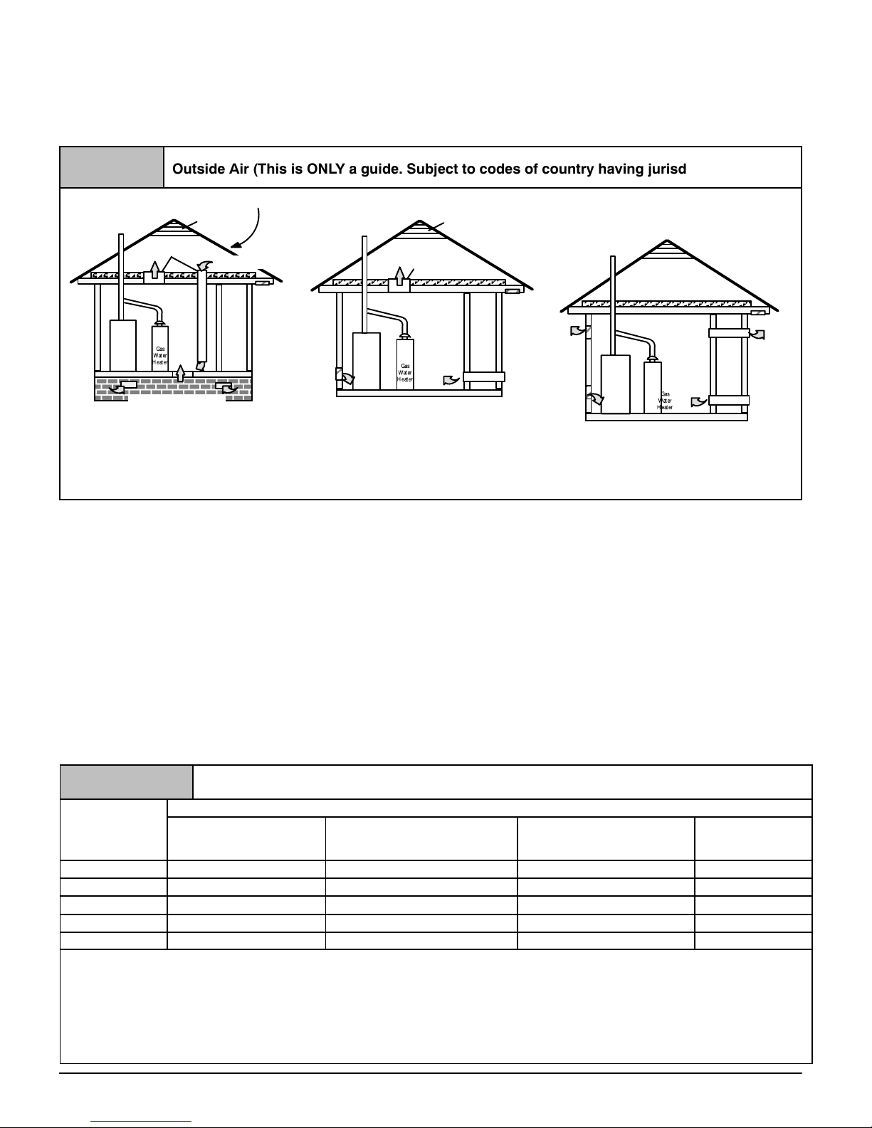
2. Figure 3 illustrates how to provide combustion and ventilation
air when two permanent openings, one inlet and one outlet, are
used.
a. One opening MUST commence within 12″ (304.8mm) of
the floor and the second opening MUST commence within
12″ (304.8mm) of the ceiling.
b. Size openings and ducts per Table 1.
Furnace
Furnace
Minimum One Inlet and One Outlet Air Supply is Required
May be in and Combination Shown
Inlet Air Opening Must be Within 12″ (304.8 mm) of floor
Outlet Air Opening Must be Within 12″ (304.8 mm) of ceiling
(1) 1 Square Inch per 4000 BTUH
(2) 1 Square Inch per 2000 BTUH
Outside Air (This is ONLY a guide. Subject to codes of country having jurisdiction.)
Figure 3
This installation NOT approved in Canada
Gas Vent
Gas Vent
Gas Vent
Gable Vent
Gable Vent
Outlet
Air (1)
Outlet Air (1)
Outlet Air (1)
Furnace
Outlet
Air (2)
Optional Inlet Air (1)
Ventilated Attic
Ventilated Attic
Ventilated Crawl Space
Inlet
Air (1)
Inlet
Air (1)
Inlet
Air (1)
Inlet
Air (2)
Inlet
Air (2)
Top Above Insulation
Top Above Insulation
Soffit Vent
Soffit Vent
c. Horizontal duct openings require 1 square inch of free area
per 2,000 BTUH (11 cm
2
/kW) of combined input for all gas
appliances in the space (see Table 1).
d. Vertical duct openings or openings directly communicating
with the outdoors require 1 square inch of free area per
4,000 BTUH (5.5 cm
2
/kW) for combined input of all gas ap-
pliances in the space (see Table 1).
3. When one permanent outdoor opening is used, the opening
requires:
a. 1 sq. in of free area per 3,000 BTUH (7 cm
2
/kW) for combined input of all gas appliances in the space (see Table 1)
and
b. Not less than the sum of the areas of all vent connectors in
the space.
The opening shall commence within 12″ (304.8mm) of the top of
the enclosure. Appliances shall have clearances of at least 1″
(25.4mm) from the sides and back and 6″ from the front. The open-
ing shall directly communicate with the outdoors or shall communicate through a vertical or horizontal duct to the outdoors or spaces
(crawl or attic) that freely communicate with the outdoors.
4. Combination of Indoor and Outdoor Air shall have:
a. Indoor openings that comply with the Indoor Combus-
tion Air Method below and
b. Outdoor openings located as required in the Outdoor
Combustion Air Method above and
c. Outdoor openings sized as follows.
1) Calculate the Ratio of all Indoor Space volume divided
by required volume for Indoor Combustion Air Method.
2) Outdoor opening size reduction Factor is 1 minus the
Ratio in 1) above.
3) Minimum size of Outdoor openings shall be the size required in Outdoor Combustion Air Method above multi-
plied by reduction Factor.
Table 1
Free Area
BTUH (kW)
Input
Rating
Minimum Free Area Required for Each Opening or Duct to Outdoors
Two Horizontal Ducts
BTUH (kW)
sq. in./2,000(1 cm
2
/.09)
Single Opening
BTUH (kW)
sq. in./3,000 (1 cm
2
/.135)
Two Vertical Ducts or Openings
BTUH (kW)
sq. in./4,000(1 cm
2
/.18)
Round Duct
BTUH (kW)
sq. in./4,000(6.5cm
2
/.18)
50,000 (14.65) 25 sq. in. (161 cm2) 16.7 sq. in. (108 cm2) 12.5 sq. in. (81 cm2) 4″ (101.6mm)
75,000 (21.98) 37.5 sq. in. (242 cm2) 25 sq. in. (161 cm2) 18.75 sq. in. (121 cm2) 5″ (127mm)
100,000 (29.31) 50 sq. in. (322 cm2) 33.3 sq. in. (215 cm2) 25 sq. in. (161 cm2) 6″ (152.4mm)
125,000 (36.63) 62.50 sq. in. (403 cm2) 41.7 sq. in. (269 cm2) 31.25 sq. in. (202 cm2) 7″ (177.8mm)
150,000 (43.95) 75 sq. in. (484 cm2) 50 sq. in. (322 cm2) 37.5 sq. in. (242 cm2) 7″ (177.8mm)
EXAMPLE: Determining Free Area
Furnace
100,000
29.31
Furnace
100,000
29.31
+
+
Water Heater
30,000
8.8
Water Heater
30,000
8.8
=
=
Total Input
(130,000 ÷ 4,000)
(38.11 ÷ .18)
Total Input
(130,000 ÷ 2,000)
(38.11 ÷ .09)
= 32.5 Sq. In. Vertical
= 210 c
m
2
Vertical
= 65 Sq. In. Horizontal
= 423
cm
2
Horizontal
441 01 2314 06
Specifications are subject to change without notice.
8
Indoor Combustion Air
!
CARBON MONOXIDE POISONING HAZARD
Failure to follow this warning could result in
personal injury or death.
Most homes will require additional air from
outdoors for combustion and ventilation. A space
with at least 50 cubic feet per 1,000 BTUH (4.8 cubic
meters per kW) input rating or homes with tight
construction may need outdoor air, supplied
through ducts, to supplement air infiltration for
proper combustion and ventilation of flue gases.
WARNING
Standard and Known-Air-Infiltration Rate Methods
NFPA & AGA
Indoor air is permitted for combustion and ventilation, if the Stan-
dard or Known−Air−Infiltration Rate Method is used.
The Standard Method may be used, if the space has no less volume than 50 cubic feet per 1,000 BTUH (4.8 cubic meters per kW)
input rating for all gas appliances installed in the space. The stan-
dard method permits indoor air to be used for combustion and ventilation air.
The Known Air Infiltration Rate Method shall be used if the in-
filtration rate is known to be less than 0.40 air changes per hour
(ACH) and equal to or greater than 0.10 ACH. Infiltration rates
greater than 0.60 ACH shall not be used. The minimum required
volume of the space varies with the number of ACH and shall be
determined per Table 2 or Equations 1 and 2. Determine the
minimum required volume for each appliance in the space, and
add the volumes together to get the total minimum required volume for the space.
Table 2
MINIMUM SPACE VOLUME FOR 100% COMBUSTION AND VENTILATION AIR FROM INDOORS
Other Than Fan-Assisted Total Fan-assisted Total
ACH
30,000 BTU
(8.79 kW)
40,000 BTU
(11.72 kW)
50,000 BTU
(14.65 kW)
50,000 BTU
(14.65 kW)
75,000
(21.98 kW)
100,000 BTU
(29.30 kW)
125,000 BTU
(36.63 kW)
150,000 BTU
(43.95 kW)
ft
3
(m3)
0.60 1,050 (29.7) 1,400 (39.2) 1,750 (49) 1,250 (35) 1,875 (52.5) 2,500 (70) 3,125 (87.5) 3,750 (105)
0.50 1,260 (35.3) 1,680 (47.04) 2,100 (58.8) 1,500 (42) 2,250 (63) 3,000 (84) 3,750 (105) 4,500 (126)
0.40 1,575 (44.1) 2,100 (58.8) 2,625 (73.5) 1,875 (52.5) 2,813 (78.8) 3,750 (105) 4,688 (131.3) 5,625 (158)
0.30 2,100 (58.8) 2,800 (78.4) 3,500 (98) 2,500 (70) 3,750 (105) 5,000 (140) 6,250 (175) 7,500 (210.6)
0.20 3,150 (88.2) 4,200 (117.6) 5,250 (147) 3,750 (105) 5,625 (157.5) 7,500 (210) 9,375 (262.5) 11,250 (316)
0.10 6,300 (176.4) 8,400 (235.2) 10,500 (294) 7,500 (210) 11,250 (315) 15,000 (420) 18,750 (525) 22,500 (632)
0.00 NP NP NP NP NP NP NP NP
NP = Not Permitted
Table 2 Minimum Space Volumes were determined by using the
following equations from the National Fuel Gas Code ANSI
Z223.1/NFPA 54−2009, 9.3.3.2:
1. For other than fan−assisted appliances such as a draft
hood−equipped water heater,
1000 BTUH
21 ft
3
(
I
other
)
Vol ume
other
=
ACH
.293 kW
59 m
3
(
I
other
)
Required Vol ume
other
ACH
2. For fan−assisted appliances such as this furnace,
If:
I
other
= combined input of all other than fan−assisted
appliances in BTUH
I
fan
= combined input of all fan−assisted appliances in
BTUH
ACH = air changes per hour (ACH shall not exceed 0.60.)
The following requirements apply to the Standard Method and to
the Known Air Infiltration Rate Method.
• Adjoining rooms can be considered part of a space, if there
are no closable doors between rooms.
• Combining spaces on the same floor level. Each opening
shall have a free area of at least 1 in.
2
/1,000 BTUH (22
cm
2
/kW) of the total input rating of all gas appliances in the
space, but not less than 100 in.
2
(645 cm2). Once opening
shall commence within 12” (604.8mm) of the ceiling and the
second opening shall commence within 12” (604.8mm) of the
floor. The minimum dimension of air openings shall be at least
3 in(76.2mm).
• An attic or crawl space may be considered a space that freely
communicates with the outdoors provided there are adequate
ventilation openings directly to outdoors. Openings MUST remain open and NOT have any means of being closed off. Ventilation openings to outdoors MUST be at least 1 square inch
of free area per 4,000 BTUH (5.5 cm
2
/kW) of total input rating
for all gas appliances in the space.
• In spaces that use the Indoor Combustion Air Method, in-
filtration should be adequate to provide air for combustion,
ventilation and dilution of flue gases. However, in buildings
with unusually tight construction, additional air MUST be provided using the methods described in section titled Outdoor
Combustion Air Method:
• Unusually tight construction is defined as Construction with:
1. Walls and ceilings exposed to the outdoors have a continuous, sealed vapor barrier. Openings are gasketed or
sealed and
2. Doors and openable windows are weather stripped and
441 01 2314 06
Specifications are subject to change without notice.
9
3. Other openings are caulked or sealed. These include
joints around window and door frames, between sole
plates and floors, between wall−ceiling joints, between
wall panels, at penetrations for plumbing, electrical and
gas lines, etc.
Ventilation Air
Some provincial codes and local municipalities require ventilation
or make−up air be brought into the conditioned space as replace-
ment air. Whichever method is used, the mixed return air temperature across the heat exchanger MUST not fall below 60° F(16° C)
continuously, or 55° F(13° C) on an intermittent basis so that flue
gases will not condense excessively in the heat exchanger. Excessive condensation will shorten the life of the heat exchanger
and possibly void your warranty.
4. Gas Vent Installation
CARBON MONOXIDE POISONING, FIRE AND
EXPLOSION HAZARD
Failure to follow this warning could result in
personal injury, death and/or property damage.
Read and follow all instructions in this section.
!
WARNING
Install the vent in compliance with codes of the country having jurisdiction, local codes or ordinances and these instructions.
This Category I furnace is fan−assisted. A fan assisted appliance
is an appliance equipped with an integral mechanical means to either draw or force products of combustion through the heat exchanger.
Category I furnace definition: A central furnace which operates
with a non−positive vent static pressure and with a flue loss not
less than 17 percent. These furnaces are approved for common−
venting and multi−story venting with other fan−assisted or draft
hood−equipped appliances in accordance with the NFGC or
NSCNGPIC.
Category I Safe Venting Requirements
Category I furnace vent installations shall be in accordance with
Parts 10 and 13 of the National Fuel Gas Code, ANSI
Z223.1/NFPA 54−2009; and/or Section 8 and Appendix C of the
CSA B149.1−05, National Standard of Canada, Natural Gas and
Propane Installation Code; the local building codes; furnace and
vent manufacturer’s instructions.
NOTE: The following instructions comply with the ANSI
Z223.1/NFPA 54 National Fuel Gas Code and CSA B149.1 Natural Gas and Propane Installation code, based on the input rate on
the furnace rating plate.
1. If a Category I vent passes through an attic, any concealed
space or floor, use ONLY Type B or Type L double wall vent
pipe. If vent pipe passes through interior wall, use Type B vent
pipe with ventilated thimble ONLY.
2. Do NOT vent furnace into any chimney serving an open fire-
place or solid fuel burning appliance.
3. Use the same diameter Category I connector or pipe as permitted by:
• the National Fuel Gas Code Code ANSI Z223.1/NFPA
54−2009 Sections 12 and 13 venting requirements in the
United States,
or
• the National Standard of Canada Natural Gas and Pro-
pane Installation Code (NSCNGPIC) CSA B149.1−05
Section 8 and appendix C venting requirements in Canada.
4. Push the vent connector onto the furnace flue collar of the
venter assembly until it touches the bead [at least
5
/8″
(15.9mm) overlap] and fasten with at least two field−supplied,
corrosion−resistant, sheet metal screws located at least 140°
apart.
5. Keep vertical Category I vent pipe or vent connector runs as
short and direct as possible.
6. Vertical outdoor runs of Type−B or ANY single wall vent pipe
below the roof line are NOT permitted.
7. Slope all horizontal runs up from furnace to the vent terminal a
minimum of
1
/4″ per foot (10mm/m)
8. Rigidly support all horizontal portions of the venting system every 6′ (1.8m) or less using proper clamps and metal straps to
prevent sagging and ensure there is no movement after installation.
9. Check existing gas vent or chimney to ensure they meet clearances and local codes. See Figure 1
10. The furnace MUST be connected to a factory built chimney or
vent complying with a recognized standard, or a masonry or
concrete chimney lined with a lining material acceptable to the
authority having jurisdiction. Venting into an unlined ma-
sonry chimney or concrete chimney is prohibited. See the
Masonry Chimney Venting section in these instructions.
11. Fan−assisted combustion system Category I furnaces shall
not be vented into single−wall metal vents.
12. Category I furnaces must be vented vertically or nearly vertically, unless equipped with a listed mechanical venter.
13. Vent connectors serving Category I furnaces shall not be connected into any portion of mechanical draft systems operating
under positive pressure.
A 4−to−3 inch (101.6−to−76.2mm) reducer is permitted at the flue
collar when installing a 50,000 BTUH (14.5 kW) gas input furnace,
if the installation meets all the following requirements for sizing the
vent connectors and vents:
1. The National Fuel Gas Code, ANSI
Z223.1/NFPA−54−2009, Sections 12.6.3.1(1),
12.7.3.1(2), 12.11.3.1, 13.1.2, 13.1 (e), and 13.2.24(1)
through (3) in the U.S. or
2. The Natural Gas and Propane Installation Code CSA
B149.1−05, Sections 8.13.1(b), 8.13.2(b), 8.18.5(b), and
Appendix C−GVR no. 2. in Canada.
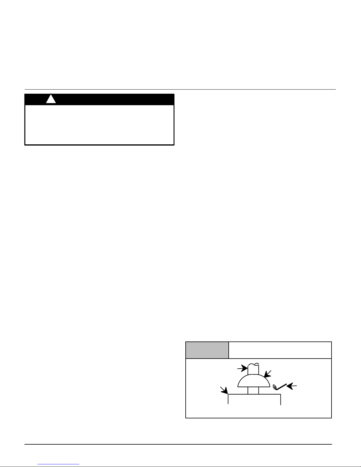
Venting and Combustion Air Check
NOTE: When an existing Category I furnace is removed or replaced, the original venting system may no longer be sized to properly vent the attached appliances, and to make sure there is
adequate combustion air for all appliances, MAKE THE FOL-
LOWING CHECK.
Vent Check
Draft HoodVent Pipe
Match
Typical Gas
Water Heater
Figure 4
NOTE: If flame pulls towards draft hood, this indicates
sufficient infiltration air.
441 01 2314 06
Specifications are subject to change without notice.
10
CARBON MONOXIDE POISONING HAZARD
Failure to follow the steps outlined below for each
appliance connected to the venting system being placed
into operation, could result in carbon monoxide
poisoning or death:
The following steps shall be followed for each appliance
connected to the venting system being placed into
operation, while all other appliances connected to the
venting system are not in operation:
1.Seal any unused openings in the venting system.
2.Inspect the venting system for proper size and horizontal
pitch, as required in the National Fuel Gas Code, ANSI
Z223.1/NFPA 54 or CSA B149.1, Natural Gas and Propane
Installation Code and these instructions. Determine that
there is no blockage or restriction, leakage, corrosion and
other deficiencies which could cause an unsafe condition.
3.As far as practical, close all building doors and windows and
all doors between the space in which the appliance(s)
connected to the venting system are located and other
spaces of the building.
4.Close fireplace dampers.
5.Turn on clothes dryers and any appliance not connected to
the venting system. Turn on any exhaust fans, such as
range hoods and bathroom exhausts, so they are operating
at maximum speed. Do not operate a summer exhaust fan.
6.Follow the lighting instructions. Place the appliance being
inspected into operation. Adjust the thermostat so
appliance is operating continuously.
7.Test for spillage from draft hood equipped appliances at the
draft hood relief opening after 5 minutes of main burner
operation. Use the flame of a match or candle. (Figure 4)
8.If improper venting is observed, during any of the above
tests, the venting system must be corrected in accordance
with the National Fuel Gas Code, ANSI Z223.1/NFPA 54
and/or CSA B149.1, Natural Gas and Propane Installation
Code.
9.After it has been determined that each appliance connected
to the venting system properly vents when tested as outlined above, return doors, windows, exhaust fans, fireplace
dampers and any other gas−fired burning appliance to their
previous conditions of use.
!
WARNING
Venting to Existing Masonry Chimney
Dedicated venting of one fan assisted furnace into any masonry chimney is restricted. A chimney must first be lined with
either Type B vent sized in accordance with NFGC tables 13.1 or
13.2 or a listed metal lining system, sized in accordance with the
NFGC Section 13.1.7 for a single appliance or 13.2.20 for multiple
appliances, or NSCNGPIC Appendix C, Section 10. (See Masonry
Chimney Venting of these instructions.)
Listed, corrugated metallic chimney liner systems in masonry
chimneys shall be sized in the U.S. by using NFGC tables per
13.1.7 for dedicated venting and per 13.2.20 for common venting
with the maximum capacity reduced by 20% (0.80 X maximum capacity) and the minimum capacity as shown in the applicable table.
Corrugated metal vent systems installed with bends or offsets require additional reduction of 5% of the vent capacity for each bend
up to 45° and 10% of the vent capacity for each bend from 45° up to
90°. In Canada, use the NSCNGPIC.
NOTE: Two(2) 45° elbows are equivalent to one (1) 90° elbow.
Combined Venting into a Masonry Chimney
Venting into a masonry or concrete chimney is only permitted
as outlined in the NFGC or NSCNGPIC venting tables. Follow
all safe venting requirements.
Note: See section “Masonry Chimney Venting”.
5. Horizontal Venting
Category I Furnaces With External Power
Venters
In order to maintain a Category I classification of fan−assisted furnaces when vented horizontally with sidewall termination, a power
venter is REQUIRED to maintain a negative pressure in the vent-
ing system.
In the U.S.: Per the NFGC, a listed power venter may be used,
when approved by the authority having jurisdiction.
In Canada: Only power venters approved by the power venter
manufacturer and where allowed by the authority having jurisdiction may be used.
Please consult the Fields Controls Co. or Tjernlund Products, Inc.
for power venters certified for use with this furnaces.
Vent Termination
Venting Through a Non-Combustible and
Combustible Wall
Consult External Power Venter manufacturer instructions.
Select the power venter to match the Btuh input of the furnace being vented. Follow all of the power venter manufacturer’s installation requirements included with the power venter for:
• venting installation,
• vent terminal location,
• preventing blockage by snow,
• protecting building materials from degradation by flue gases,
• see Figure 5 for required vent termination.
NOTE: It is the responsibility of the installer to properly terminate
the vent and provide adequate shielding. This is essential in order
to avoid water/ice damage to building, shrubs and walkways.
 Loading...