

Page 1
These instructions must be read and understood completely before attempting installation.
Safety Labeling and Signal Words
DANGER, WARNING, CAUTION, and
NOTE
The signal words DANGER, WARNING, CAU-
TION, and NOTE are used to identify levels of haz-
ard seriousness. The signal word DANGER is only
used on product labels to signify an immediate haz-
ard. The signal words WARNING, CAUTION, and
NOTE will be used on product labels and through-
out this manual and other manuals that may apply
to the product.
DANGER - Immediate hazards which will result in
severe personal injury or death.
WARNING - Hazards or unsafe practices which
could result in severe personal injury or death.
CAUTION - Hazards or unsafe practices which
may result in minor personal injury or product or
property damage.
NOTE - Used to highlight suggestions which will
result in enhanced installation, reliability, or opera-
tion.
Signal Words in Manuals
The signal word WARNING is used throughout this
manual in the following manner:
The signal word CAUTION is used throughout this
manual in the following manner:
Signal Words on Product Labeling
Signal words are used in combination with colors
and/or pictures on product labels.
TABLE OF CONTENTS
Introduction .................................... 2
Location ....................................... 2
Position Unit ................................... 4
Air Ducts ...................................... 5
Electrical Connections .......................... 5
Refrigerant Tubing .............................. 6
Refrigerant Metering Device ..................... 6
Condensate Drains ............................. 6
Schematic ..................................... 8
Sequence of Operation ......................... 10
Care and Maintenance ......................... 10
Parts ........................................ 11
DEATH, PERSONAL INJURY, AND/OR PROPERTY
DAMAGE HAZARD
Failure to carefully read and follow this warning
could result in equipment malfunction, property
damage, personal injury and/or death.
Installation or repairs made by unqualified per-
sons could result in equipment malfunction, prop-
erty damage, personal injury and/or death.
The information contained in this manual is in-
tended for use by a qualified service technician fa-
miliar with safety procedures and equipped with
the proper tools and test instruments.
Installation must conform with local building
codes and with the National Electrical Code
NFPA70 current edition.
Specifications are subject to change without notice 496 01 2100 02 June 2006
Page 2
I _:o_: .......l_I',l_ _!I_ .......
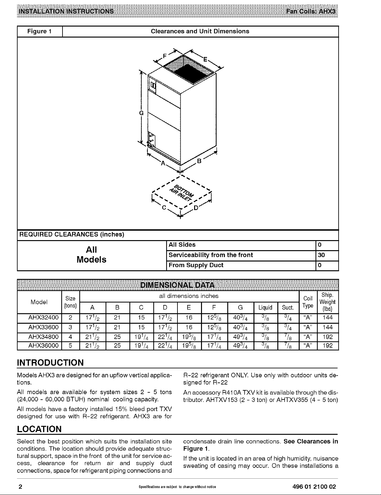
Figure 1 Clearances and Unit Dimensions
" X _ _w" / "
REQUIRED CLEARANCES (inches)
All Sides 0
All
Models Serviceability from the front 30
From Supply Duct 0
Size all dimensions inches Coil Ship.
Model (tons) A B C D E F G Liquid Suct. Type (tbs)
AHX32400 2 171/2 21 15 171/2 16 125/8 403/4 3/8 3/4 "A" 144
AHX33600 3 171/2 21 15 171/2 16 125/8 403/4 3/8 3/4 "A" 144
AHX34800 4 211/2 25 191/4 221/4 195/8 171/4 493/4 3/8 7/8 "A" 192
AHX36000 5 211/2 25 191/4 221/4 195/8 171/4 493/4 3/8 7/8 "A" 192
INTRODUCTION
Models AHX3 are designed for an upfiow vertical applica-
tions.
All models are available for system sizes 2 - 5 tons
(24,000 - 60,000 BTUH) nominal cooling capacity.
All models have a factory installed 15% bleed port TXV
designed for use with R-22 refrigerant. AHX3 are for
R-22 refrigerant ONLY. Use only with outdoor units de-
signed for R-22
An accessory R410A TXV kit is available through the dis-
tributor. AHTXV153 (2 - 3 ton) or AHTXV355 (4 - 5 ton)
Weight
LOCATION
Select the best position which suits the installation site
conditions. The location should provide adequate struc-
tural support, space in the front of the unit for service ac-
cess, clearance for return air and supply duct
connections, space for refrigerant piping connections and
2 Specifications are subject to changewithout notice 496 01 2100 02
condensate drain line connections. See Clearances in
Figure 1.
If the unit is located in an area of high humidity, nuisance
sweating of casing may occur. On these installations a
Page 3
wrap of 2" fiberglass insulation with a vapor barrier is rec-
ommended.
NOTE: Internal filter can be accessed from separate filter
door. If the filter can NOT be easily accessed, a remote
filter is recommended. Refer to ACCA Manual D for re-
mote filter sizing.
FIRE HAZARD
Failure to maintain proper clearances could result
in personal injury, death, and/or property damage.
When heaters are installed, maintain clearances
from combustible materials as specified on unit
rating plate. Do not use plastic lined or combus-
tible flexible ducting within 36 inches of the supply
end of the fan coil.
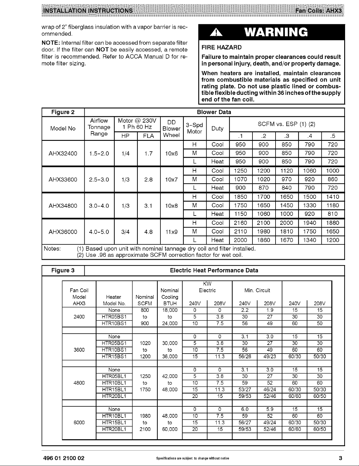
Figure 2
Airflow Motor @ 230V DD
Model No
Tonnage 1 Ph 60 Hz Blower 3-Spd
Range HP FLA Wheel
AHX32400 1.5-2.0 1/4 1.7 10x6
AHX33600 2.5-3.0 1/3 2.8 10x7
AHX34800 3.0-4.0 1/3 3.1 10x8
AHX36000
Notes:
4.0-5.0 3/4 4.8 11x9
(1) Based upon unit with nominal tannage dry coil and filter installed,
(2) Use ,96 as approximate SCFM correction factor for wet coil,
Figure 3 1
Fan Coil
Model
AHX3
2400
Heater
Model No.
None
HTR05BS 1
HTR10BS 1
Nominal
SCFM
800
900
Nominal
Cooling
18,000
to
24,000
Blower Data
Motor
H
M
L
H
M
L
H
M
L
H
M
L
Duty
,1 ,2 ,3 ,4 ,5
Cool 950 900 850 790 720
Cool 950 900 850 790 720
Heat 950 900 850 790 720
Cool 1250 1200 1120 1060 1000
Cool 1070 1020 970 920 860
Heat 900 870 840 790 720
Cool 1850 1700 1650 1500 1410
Cool 1750 1650 1450 1330 1180
Heat 1150 1060 1000 920 810
Cool 2160 2100 2000 1940 1880
Cool 2110 1980 1810 1750 1650
Heat 2000 1860 1670 1340 1200
Electric Heat Performance Data
KW
Electric
BTUH
to
240V 208V
0 0
5 3.8
10 7.5
240V 208V
SCFM vs, ESP (1) (2)
Min. Circuit
2.2 1.9
30 27
56 49
240V I
15
30
60
208V
15
30
50
3600
48OO
6000
None
HTR05BS1
HTR10BS1
HTR15BS1
None
HTR05BL1
HTR10BL1
HTR15BL1
HTR20BL1
None
HTR10BL1
HTR15BL1
HTR20BL1
1020
to
1200
1250
to
1750
1980
to
2100
30,000
to
36,000
42,000
to
48,000
48,000
to
60,000
0 0
5 3.8
10 7.5
15 11.3
0 0
5 3.8
10 7.5
15 11.3
20 15
0 0
10 7.5
15 11.3
20 15
3.1 3.0
30 27
56 49
56/26 49/23
3.1 3.0
30 27
59 52
53/27 46/24
59/53 52/46
6.0 5.9
59 52
56/27 49/24
59/53 52/46
15
30
60
60/30
15
30
60
60/30
60/60
15
60
60/30
60/60
15
30
60
50/30
15
30
60
50/30
60/50
15
60
50/30
60/50
496 01 2100 02 Specifications are subject to changewithout notice 3
Page 4
POSITION UNIT
Unit is designed to be installed in a closet or flush
mounted. Can be serviced entirely from the front, includ-
ing replacing the filter. Allow space for wiring, piping, and
servicing unit.
PROPERTY DAMAGE HAZARD
Failure to follow this caution may result in proper-
ty damage
A field fabricated auxiliary drain pan, with a sepa-
rate drain is REQUIRED for all installations over a
finished living space or in any area that may be
damaged by overflow from a restricted main drain
pan. In some localities, local codes require an aux-
iliary drain pan for ANY horizontal installation.
A. UPFLOW INSTALLATION
If return air isto be ducted through a floor, set unit on floor
over opening and use 1/8 to i/4 inch thick fireproof resil-
ient gasket between duct, unit, and floor.
Exterior surface may sweat when unit is installed in non-
conditioned space. Installer must provide protection such
as full size auxiliary drain pan on all units installed in non-
conditioned space to prevent damage from condensation
runoff. It is recommended that units be insulated with 1"
thick fiberglass with the vapor barrier on the outside.
B. HORIZONTAL APPLICATION
Units are shipped in right to left configuration. Horizontal
applications require a return air duct be attached to the
furnace inlet. The opposite end of the return air duct is at-
tached to a return air filter grill through the ceiling or wall.
For left to right applications:
1. Remove and set aside front panels.
2. Remove the coil support bracket (4 screws).
3. Remove horizontal drain pan retaining clip (1
screw).
4. Carefully remove coil assembly and bottom drain
pan.
5. Move Horizontal drain pan from left hand side of
coil to right.
6. Install modified coil assembly back into unit.
7. Reinstall coil support bracket and horizontal drain
pan retaining clip.
8. Determine drain holes being used and reposition
knockout caps.
9. Reinstall doors.
AIR DUCTS
Connect supply-air duct over the outside of %" flanges
provided on supply-air opening. Secure duct to flange us-
ing proper fasteners for type of duct used, and seal duct-
to-unit joint. If return-air flanges are required, install
factory authorized accessory kit.
Use flexible connectors between duct work and unit to
prevent transmission of vibration. Duct work passing
through unconditioned space must be insulated and cov-
ered with vapor barrier to prevent formation of conden-
sate to prevent formation of condensate.
ELECTRICAL CONNECTIONS
Refer to the unit's nameplate for specific electrical data.
Before proceeding with electrical connections, make cer-
tain that supply voltage, frequency, phase, and circuit am-
pacity are as specified on the unit rating plate. Make all
electrical connections in accordance with the NEC and
any local codes or ordinances that may apply. Use cop-
per wire rated for 75 degrees C minimum wire in the unit
wiring compartment only. A single power supply may be
connected directly to terminal block provided in the unit.
Duct work Acoustical Treatment
Metal duct systems that do not have a 90 degree elbow
and 10 feet of main duct before first branch takeoff may
require internal acoustical insulation lining. As an alterna-
tive, fibrous duct work may be used if constructed and
installed in accordance with the latest edition of SMACNA
construction standard on fibrous glass ducts. Both acous-
tical lining and fibrous duct work shall comply with Nation-
al Fire Protection Association as tested by UL Standard
181 for Class 1 air ducts.
ELECTRICAL SHOCK or UNIT DAMAGE HAZARD
Failure to follow this warning could result in per-
sonal injury, death, and/or unit damage.
Ifa disconnect switch is to be mounted on unit, se-
lect a location where drill and fasteners will not
contact electrical or refrigeration components.
4 Spe¢ificationsaresubiect to changewithout notice 496 01 2100 02
Page 5

Figure 4 L Transformer Connections
ELECTRICAL SHOCK HAZARD
Failure to follow this warning could result in per-
sonal injury or death.
Turn off the main (remote) disconnect device be-
fore working on incoming (field) wiring.
Incoming (field) wires on the line side of the dis-
connect found in the fan coil unit remain live, even
when the pull-out is removed. Service and main-
tenance to incoming (field) wiring cannot be per-
formed until the main disconnect switch (remote
to the unit) is turned off.
A. LINE VOLTAGE CONNECTIONS
This Fan Coil is not electric heat compatable.
1. Connect 208/240V power leads from field discon-
nect to units high voltage terminal block.
2. Connect ground wire to unit ground lug.
B. 24V CONTROL SYSTEM
Connection to Unit
Wire low voltage in accordance with wiring label on the
unit. Use 18 AWG color-coded, insulated (35 degrees C
minimum) wire to make the low-voltage connections be-
tween the thermostat, the unit, and the outdoor equip-
ment. If the thermostat is located more than 100feet from
the unit (as measured along the low voltage wire), use 16
AWG color-coded, insulated (35 degrees C minimum)
wire. All wiring must be NEC Class 2 and must be sepa-
rated from incoming power leads. Refer to outdoor unit
wiring instructions for additional wiring recommenda-
tions.
NOTE: Before proceeding with electrical connections,
make certain that supply voltage, frequency, phase, and
circuit ampacity are as specified on the unit rating plate.
See unit wiring label for proper field high and low voltage
wiring. Make all electrical connections in accordance with
the NEC and any local codes or ordinances that may ap-
ply. Use copper wire only. The unit must have a separate
branch electric circuit with a field-supplied disconnect
switch located within sight from, and readily accessible
from the unit.
Transformer Information
Transformer is factory wired for 208/240V operation.
ll_m ==== m RED
_L_% 24VAC
BLA:CK
C. GROUND CONNECTIONS
ELECTRICALSHOCKHAZARD
Failure to establish uninterrupted or unbroken
ground could result in personal injury and/or
death.
According to NEC, ANSI/NFPA 70, and local
codes, the cabinet must have an uninterrupted or
unbroken ground in order to minimize potential
for personal injury or death if an electrical fault
should occur. The ground may consist of electri-
cal wire or metal conduit when installed in accor-
dance with existing electrical codes. If conduit
connection uses reducing washers, a separate
ground wire must be used.
NOTE: Use UL listed conduit and conduit connectors for
connecting supply wire(s) to unit to obtain proper ground-
ing. Grounding may also be accomplished by using
grounding lugs provided in control box.
D. MINIMUM CFM AND MOTOR SPEED SELECTION
Units require a minimum CFM. Refer to the unit wiring la-
bel to ensure that the fan speed selected is not lower than
the minimum fan speed indicated.
Fan speed selection is done at the fan relay. To change
motor speeds, disconnect fan lead used on relay terminal
(FR) and replace with motor speed lead desired (refer to
Figure 8). Save insulating cap and place on motor lead
removed from relay.
1
1_ANSFORME8
496 01 2100 02 Specifications are subiect to changewithout notice 5
Page 6
NOTE: In low static applications, lower motor speed tap
should be used to reduce possibility of water being blown
off coil.
All units have three (3) motor speed taps. Low speed (red
or 4) is designed for mismatch outdoor unit applications.
REFRIGERANT TUBING
Medium speed (blue or 3) is designed for straight
matched operations. High speed (black or 2) is used with
high external static duct situations on straight matched
systems.
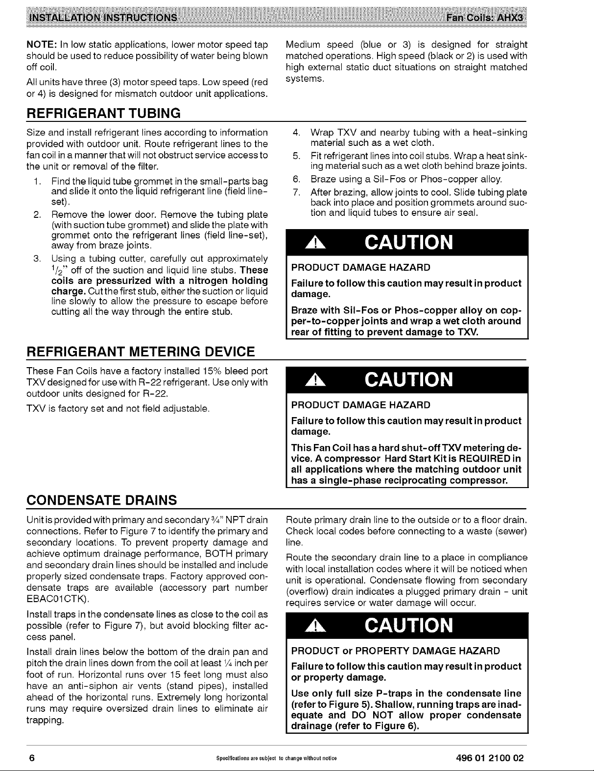
Size and install refrigerant lines according to information
provided with outdoor unit. Route refrigerant lines to the
fan coil in a manner that will not obstruct service access to
the unit or removal of the filter.
1. Find the liquid tube grommet in the small-parts bag
and slide it onto the liquid refrigerant line (field line-
set).
2. Remove the lower door. Remove the tubing plate
(with suction tube grommet) and slide the plate with
grommet onto the refrigerant lines (field line-set),
away from braze joints.
3. Using a tubing cutter, carefully cut approximately
1/2" off of the suction and liquid line stubs. These
coils are pressurized with a nitrogen holding
charge, Cut the first stub, either the suction or liquid
line slowly to allow the pressure to escape before
cutting all the way through the entire stub.
REFRIGERANT METERING DEVICE
These Fan Coils have a factory installed 15% bleed port
TXV designed for use with R-22 refrigerant. Use only with
outdoor units designed for R-22.
TXV is factory set and not field adjustable.
4. Wrap TXV and nearby tubing with a heat-sinking
material such as a wet cloth.
5. Fit refrigerant lines into coil stubs. Wrap a heat sink-
ing material such as a wet cloth behind braze joints.
6. Braze using a SiI-Fos or Phos-copper alloy.
7. After brazing, allow joints to cool. Slide tubing plate
back into place and position grommets around suc-
tion and liquid tubes to ensure air seal.
PRODUCT DAMAGE HAZARD
Failure to follow this caution may result in product
damage.
Braze with SiI-Fos or Phos-copper alloy on cop-
per-to-copper joints and wrap a wet cloth around
rear of fitting to prevent damage to TXV.
PRODUCT DAMAGE HAZARD
Failure to follow this caution may result in product
damage.
This Fan Coil has a hard shut-off TXV metering de-
vice. A compressor Hard Start Kit is REQUIRED in
all applications where the matching outdoor unit
has a single-phase reciprocating compressor.
CONDENSATE DRAINS
Unit is provided with primary and secondary 3/4"NPT drain
connections. Refer to Figure 7 to identify the primary and
secondary locations. To prevent property damage and
achieve optimum drainage performance, BOTH primary
and secondary drain lines should be installed and include
properly sized condensate traps. Factory approved con-
densate traps are available (accessory part number
EBAC01 CTK).
Install traps in the condensate lines as close to the coil as
possible (refer to Figure 7), but avoid blocking filter ac-
cess panel.
Install drain lines below the bottom of the drain pan and
pitch the drain lines down from the coil at least ¼ inch per
foot of run. Horizontal runs over 15 feet long must also
have an anti-siphon air vents (stand pipes), installed
ahead of the horizontal runs. Extremely long horizontal
runs may require oversized drain lines to eliminate air
trapping.
6 Specificatio._a,esubiect to change without notice 496 01 2100 02
Route primary drain line to the outside or to a floor drain.
Check local codes before connecting to a waste (sewer)
line.
Route the secondary drain line to a place in compliance
with local installation codes where it will be noticed when
unit is operational. Condensate flowing from secondary
(overflow) drain indicates a plugged primary drain - unit
requires service or water damage will occur.
PRODUCT or PROPERTY DAMAGE HAZARD
Failure to follow this caution may result in product
or property damage.
Use only full size P-traps in the condensate line
(refer to Figure 5). Shallow, running traps are inad-
equate and DO NOT allow proper condensate
drainage (refer to Figure 6).
Page 7

Prime all traps, test for leaks, and insulate drain lines
where sweating could cause water damage. Consult local
codes for additional requirements or precautions.
If a gravity drain cannot be used, install a condensate
pump. Install the pump as close to the indoor section as
possible.
Be sure to install plastic push-in plugs in unused conden-
sate drain holes.
PRODUCT DAMAGE HAZARD
Figure 6 [ Insufficient Condensate Trap
Failure to follow this caution may result in poor
unit performance and/or product damage.
Never operate unit without a filter. Factory autho-
rized filter kits must be used when locating the fil-
ter inside the unit. For those applications where
access to an internal filter is impractical, a field-
supplied filter must be installed in the return duct
system.
Figure 5
I Recommended Condensate Trap
2" MIN
DO NOT USE SHALLOW RUNNING TRAPS!
Figure 7
[
Condensate Drain
0
0
SECONDARY DRAIN WITH
APPROPIATE TRAP REQUIRED
(USE FACTORY KIT OR
FIELD - SUPPLIED TRAP)
PRIMARY TRAP REQUIRED (USE FACTORY KIT OR
FIELD - SUPPLIED TRAP OF PROPER DEPTH.
STANDARD P - TRAPS ARE NOT SUFFICENT. SEE
FIGURE OF RECOMMENDED CONDENSATE TRAP)
-FILTER
ACCESS
PANEL
496 01 21 O0 02 Specifications aresubject to change without notice 7
Page 8

I _:o_: .......I_NS _!I_ .......
Figure 8 1
Ii
o o
Wiring Layout - Cooling
i i
m
I
I
iiii|
I I
I I o
I
l|
I _ II' :o
8 Specificatiolls aresubiect to change without notice 496 01 21 O0 02
r
Page 9

Figure 9 1 Wiring Layout - Electric Heating
ii I__
I _ _
I I I --"_
I I I I
I
496 01 21 O0 02 S_ec]fic.tio._aresubiect to changewithoutnotice 9
........_L..!q_-_ -.io
_&__
Page 10

SEQUENCE OF OPERATION
A. CONTINUOUS FAN
Thermostat closes R to G.
G energizes Time Delay Relay (TDR).
Time Delay Relay (TDR) energizes Fan Relay (FR)
within 30 seconds.
When Fan Relay (FR) is energized, circuit is com-
plete to Indoor Blower Motor.
When G is de-energized, there is a 3 second delay
before Fan Relay (FR) opens.
B. COOLING MODE
Thermostat closes R to G, R to Y, and R to O (heat
pump only).
G energizes Time Delay Relay (TDR). Y energizes
Condense contactor, and O energizes the reversing
valve (heat pump only)
Time Delay Relay (TDR) energizes Fan Relay (FR)
within 30 seconds.
When Fan Relay (FR) is energized, circuit is com-
plete to Indoor Blower Motor.
When G is de-energized, there is a 3 second delay
before Fan Relay (FR) opens.
CARE AND MAINTENANCE
SAFETY SWITCHES
Unit is equipped with a limit switch for each sepa-
rate heating element.
These switches are normally closed and are set to
open at170 ° E
Blower continues running until unit has cooled
enough (below set point) for switches to automati-
cally reset.
C. HEATING MODE
Thermostat closes R to W and R to G.
W closes the Heat Sequencer(s) to switch line volt-
age from Terminals 1 and 4 to Terminals 3 and 5,
which energizes the Heating Elements.
G energizes the Time Delay Relay (TDR).
Time Delay Relay (TDR) energizes Fan Relay (FR)
within 30 seconds.
When Fan Relay (FR) is energized, circuit is com-
plete to Indoor Blower motor.
When G is de-energized there is a 3 second delay.
The system should be regularly inspected by a qualified
service technician. Consult the servicing dealer for rec-
ommended frequency.
Between visits, the only consumer service recommended
or required is air filter maintenance and condensate drain
operation.
Air Filter
Air handlers are factory equipped with an air filter. If the
return grille has its own filter, it is not recommended to
install a filter in the Air handler.
Inspect air filters at least monthly and replace or clean as
required. Disposable type filters should be replaced. Re-
usable type filters may be cleaned by soaking in mild de-
tergent and rinsing with cold water. Install filters with the
arrows on the side pointing in the direction of air flow.
Condensate Drain
During the cooling season check at least monthly for free
flow of drainage and clean if necessary.
10 Specification_a,esubiect to changewithout notice 496 01 2100 02
Page 11

AHX3 Series
NOTE: This illustration is for
reference only. Your unit may
differ in appearance or may not
include all components shown.
@
38- 11- 87a
496 01 21O0 02 Speciticatio_ls aresubject to change withoutnotice 11
Page 12
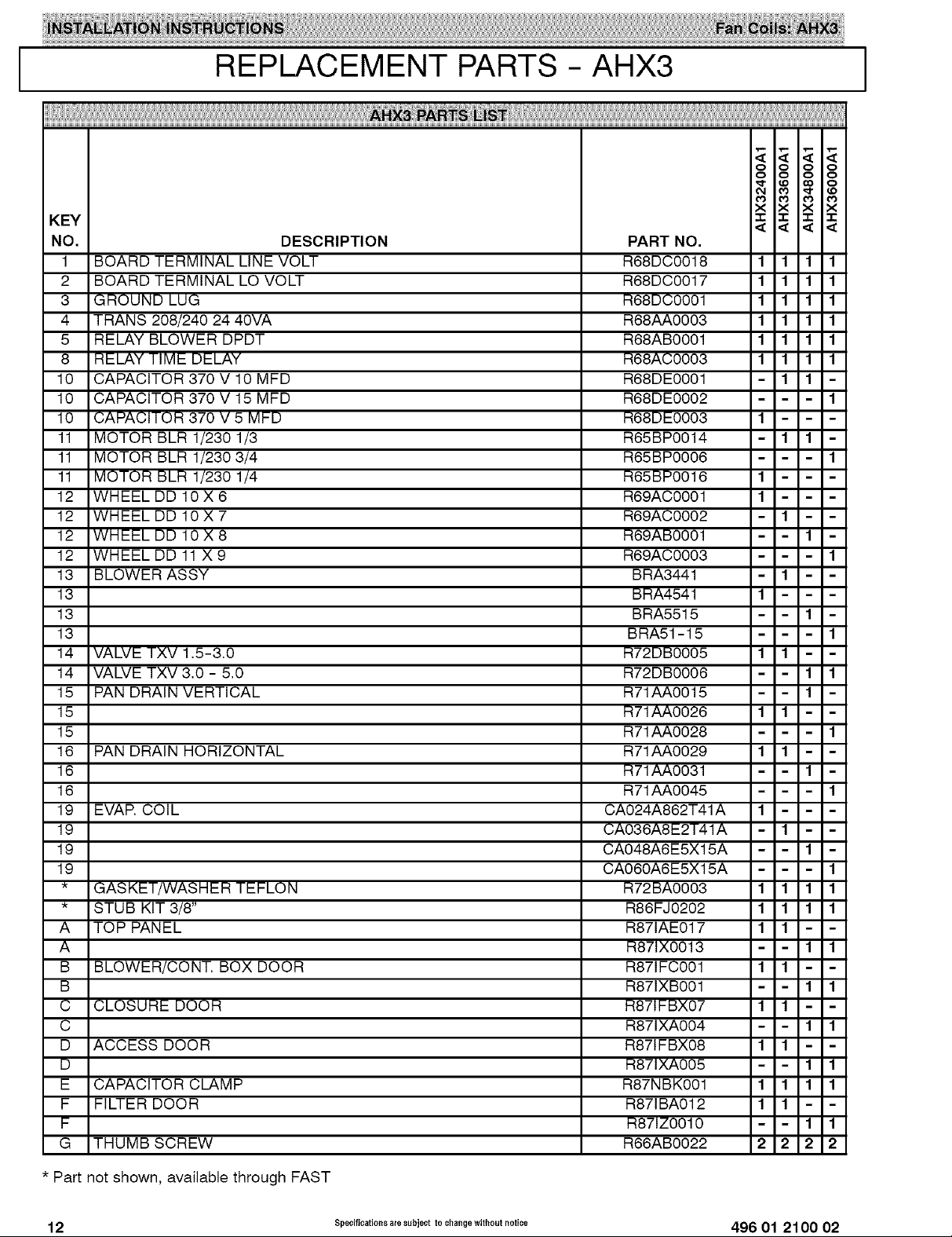
KEY
NO.
1
BOARD TERMINAL LINE VOLT
2
BOARD TERMINAL LO VOLT
3
GROUND LUG
4
TRANS 208/240 24 40VA
5
RELAY BLOWER DPDT
8
RELAY TIME DELAY
10
CAPACITOR 370 V 10 MFD
10
CAPACITOR 370 V 15 MFD
10
CAPACITOR 370 V 5 MFD
11
MOTOR BLR 1/230 1/3
11
MOTOR BLR 1/230 3/4
11
MOTOR BLR 1/230 1/4
12
WHEEL DD 10X6
12
WHEEL DD 10X7
12
WHEELDD10X8
12
WHEEL DD 11 X 9
13
BLOWER ASSY
13
13
13
14
VALVE TXV 1,5-3,0
14
VALVE TXV 3,0 - 5,0
15
PAN DRAIN VERTICAL
15
15
16
PAN DRAIN HORIZONTAL
16
16
19
EVAR COIL
19
19
19
GASKET/WASHER TEFLON
STUB KIT 3/8"
A
TOP PANEL
A
B
BLOWER/CONT, BOX DOOR
B
C
CLOSURE DOOR
C
D
ACCESS DOOR
D
E
CAPACITOR CLAMP
F
FILTER DOOR
F
G
THUMB SCREW
REPLACEMENT PARTS - AHX3
DESCRIPTION
PART NO,
R88DC0018 I I I I
R88DC0017 I I I I
R88DC0001 I I I I
R88_J_,0003 I I I I
R68AB0001 1 1 1 1
R68AC0003 1 1 1 1
R68DE0001 - 1 1
R68DE0002 - - 1
R68DE0003 1 -
R65BP0014 - 1 1
R65BP0006 - - 1
R65BP0016 1 -
R69AC0001 1 -
R69AC0002 - 1 -
R69AB0001 - 1
R69AC0003 - - 1
BRA3441 - 1 -
BRA4541 1 -
BRA5515 - 1
BRA51-15 - - 1
R72DB0005 1 1 -
R72DB0006 - 1 1
R71AA0015 - 1
R71AA0026 1 1 -
R71AA0028 - - 1
R71AA0029 1 1 -
R71AA0031 - 1
R71AA0045 - - 1
CA024A862T41A 1 -
CA036A8E2T41A - 1 -
CA048A6E5X15A - 1
CA060A6E5X15A - - 1
R72BA0003 1 1 1 1
R86FJ0202 1 1 1 1
R871AE017 1 1 -
R871X0013 - 1 1
R871FC001 1 1 -
R871XB001 - 1 1
R871FBX07 1 1 -
R871XA004 - 1 1
R871FBX08 1 1 -
R871XA005 - 1 1
R87NBK001 1 1 1 1
R871BA012 1 1 -
R871Z0010 - 1 1
R66AB0022 2 2 2 2
O O O O
O O O O
X X X X
"r "r "r -r
I
* Part not shown, available through FAST
12 Specifications aresubject tochaagewithout notice 496 01 2100 02
 Loading...