

ICP *9MPT050F12, *9MPT100J16, *9MPT075F14, *9MPT125L20, *9MPV050F12 Installation Instruction
...Page 1
*9MPT & *9MPV
FAN ASSISTED,
DIRECT OR NON--DIRECT VENT
GAS FURNACE
* Denotes Brands (C, H, T)
SAFETY REQUIREMENTS
Recognize safety information. This is the safety-- alert symbol!. When you see this symbol on the furnace and in instructions manuals be alert to
the potential for personal injury.
Understand the signal words DANGER,WARNING,or CAUTION. These words are used with the safety--alertsymbol. DANGER identifies the most
serious hazards, those that willresult in severe personal injury or death. WARNING signifies a hazard that could result in personal injury or death.
CAUTION is used to identify unsafe practices that may result in minor personal injury or product and property damage. NOTE is used to highlight
suggestions that will result in enhanced installation, reliability, or operation.
Installing and servicing heating equipment can be hazardous due to gas and electrical components. Only trained and qualified personnel should
install, repair, or service heating equipment.
Untrained service personnel can perform basic maintenance functions such as cleaning and replacing air filters. All other operations must be
performed by trained service personnel. When working on heating equipment, observe precautions in the literature, on tags, and on labels attached
to or shipped with the unit and other safety precautions that may apply.
Follow all safety codes. In the United States, follow all safety codes including the current edition National Fuel Gas Code (NFGC) ANSI
Z223.1--2002/NFPA No. 54--2002. In Canada, refer to the current edition of the National Standard of Canada Natural Gas and Propane Installation
Code (NSCNGPIC) CSA B149.1--05. Wear safety glasses and work gloves. Have fire extinguisher available during start --up and adjustment
procedures and service calls.
These instructions cover minimum requirements and conform to existing national standards and safety codes. In some instances, these instructions
exceed certain local codes and ordinances, especially those that may not have kept up with changing residential construction practices. We require
these instructions as a minimum for a safe installation.
Ò
International Comfort Products, LLC
Lewisburg, TN 37091
1. Safe Installation Requirements 3...................
2. Installation 4..................................
3. Combustion & VentilationAir 8....................
4. Vent & Combustion Air Piping 11...................
5. Concentric VentTermination 29....................
6. Gas Supply and Piping 32........................
!
WARNING
ELECTRIC SHOCK HAZARD
Failure to follow safety
warnings exactly could result
in serious injury and/or death.
Turn Off All Power Before
Servicing.
Ò
Table of Contents
INSTALLER: Affix these instructions
on or adjacent to the furnace.
CONSUMER: Retain these
instructions for future reference.
7. ElectricalWiring 35............................
8. Ductworkand Filter 37.........................
9. Checksand Adjustments 40.....................
10. Furnace Maintenance 43........................
11. Sequenceof Operation & Diagnostics *9MPV 44......
12. Sequence of Operation & Diagnostics *9MPT 46......
TechSupport and Parts 49.........................
!
CARBON MONOXIDE POISONING AND FIRE
HAZARD.
Failuretofollowsafetywarnings exactly could
result in serious injury,death,and/or property
damage.
This furnace is not designed for use in mobile
homes, trailers or recreational vehicles.
WARNING
PrintedinU.S.A. 07/18/2005 440 01 2021 (01)
Page 2
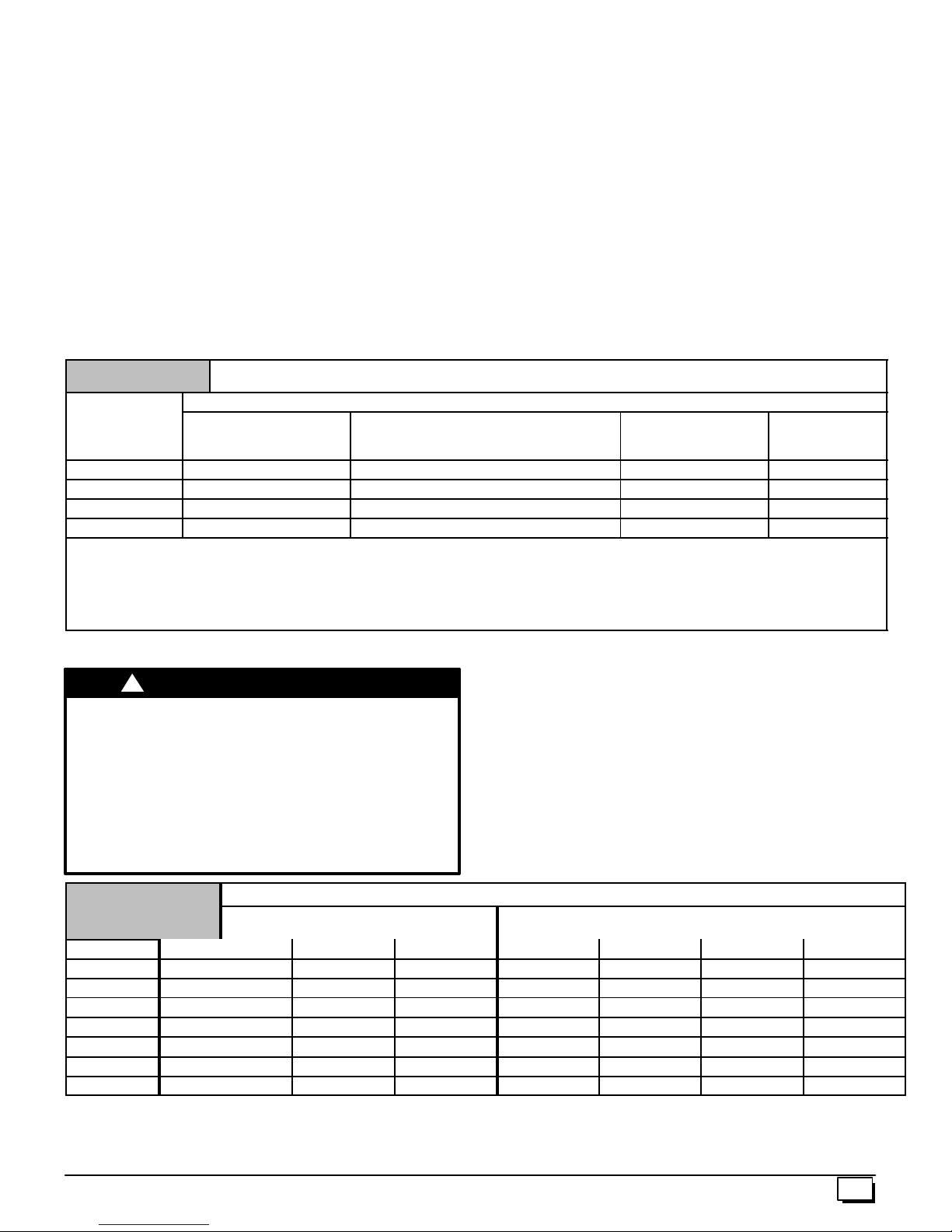
START--UP CHECK SHEET
For 90+ Furnace
(Keep this page for future reference)
Dealer Name:
Address: Business Card Here
City, State(Province), Zip or Postal Code:
Phone:
Owner Name:
Address:
City, State(Province), Zip or Postal Code:
Model Number:
Serial Number:
Type of Gas: Natural: LP:
Which blower speed tap is used?
High Fire
For variable speed models (*9MPV), What dip switches are
selected?
High Fire
Temperature of Supply Air: High Fire (°F) or (°C)
Temperature of Return Air: (°F) or (°C)
Temp. Rise Hi Fire (Supply -- Return ): (°F) or (°C)
Lo Fire (Supply -- Return ): (°F) or (°C)
Low Fire or (Cooling)
Low Fire or (Cooling)
Low Fire (°F) or (°C)
Manual Gas Shut--Off Upstream
of Furnace/Drip--Leg? YES
Condensate Drain Connected? YES NO
Condensate Drain Trapped? YES NO
Transition Pressure switch hose relocated for U/D/H
Application? YES
Blower Speed Checked? YES NO
All Electrical Connections Tight? YES NO
Gas Valve turned ON? YES NO
Measured Line Pressure When Firing Unit:
Calculated Firing Rate:(See Checks and Adjustments Sec-
tion). (Lo)
Temperature Rise (supply--return temperature):(°F)
Measured Manifold Gas Pressure: (Lo) &(Hi)
Static Pressure (Ducts): Supply Air Return
NO
&(Hi)
NO
Filter Type and Size:
Fan “Time ON” Setting:
Fan “Time OFF” Setting:
Dealer Comments:
2
Date of Start--Up:
CO ?
CO2 ?
440 01 2021 01
Page 3
1. Safe Installation Requirements
!
WARNING
FIRE, EXPLOSION, AND ASPHIXIATION HAZARD
Improper adjustment, alteration, service,
maintanence or installation could cause death,
personal injury and/or property damage.
Installation or repairs made by unqualified persons
could result in hazards to you and others.
Installation MUST conform with local codes or, in
the absence of local codes, with codes of all
governmental authorities having jurisdiction.
The information contained in this manual is
intended for use by a qualified service agency that
is experienced in such work, is familiar with all
precautions and safety procedures required in
such work, and is equipped with the proper tools
and test instruments.
NOTE: This furnace is design--certified by the CSA International
(formerly AGA and CGA) for installation in the United States and
Canada. Refer to the appropriate codes, along with this manual,
for proper installation.
· Use only the Type of gas approved for this furnace (see
RatingPla te on unit). Overfiring will result in failure of heat
exchanger and cause dangerous operation. (Furnaces
can be converted to L.P. gas with approved kit.)
· Install this furnace only in a location and position as speci-
fied in “2. Installation” of these instructions.
· Provide adequate combustion and ventilation air to the fur-
nace as specified in “4. Combustionand VentilationAir” of
these instructions.
· Combustion products must be discharged outdoors. Con-
nect this furnace to an approved vent system only, as spe-
cified in “5. Combustion and Ventilation Air, 6. Horizontal
Venting and 7. Masonry Chimney Venting” of these in-
structions.
· Never test for gas leaks with an open flame. Use a com-
mercially available soap solution made specifically for the
detection of leaks to check all connections, as specified in
“8. Gas Supply and Piping, Final Check” of these instruc-
tions.
· Always install furnace to operate within the furnace’s in-
tended temperature--rise range with a duct system which
has an external static pressure within the allowable range,
as specified in “Technical Support Manual” of these in-
structions. See furnace rating plate.
· When a furnace is installed so that supply ducts carry air
circulated by the furnace to areas outside the space containing the furnace, the return air shall also be handled by a
duct(s) sealed to the furnace casing and terminating outside the space containing the furnace.
· A gas--fired furnace for installation in a residential garage
must be installed as specified in “2. Installation Requirements” of these instructions.
· This furnace is not to be used for temporary heating of
buildings or structures under construction.
· This furnace is NOT approved for installation in mo-
bile homes, trailers or recreation vehicles.
· Seal around supply and return air ducts.
· Install correct filter type and size.
· Unit MUST be installed so electrical components are pro-
tected from direct contact with water.
Safety Rules
Your unit is built to provide many years of safe and dependable
service providing it is properly installed and maintained. However,
abuse and/or improper use can shorten the life of the unit and
create hazards for you, the owner.
A. The U.S. Consumer Product Safety Commission encourages
installation of carbon monoxide alarms. There can be various
sources of carbon monoxide in a building or dwelling. The
sources could be gas--fired clothes dryers, gas cooking
stoves, water heaters, furnaces, gas--fired fireplaces, wood
fireplaces.
Carbon monoxide can cause serious bodily injury and/or
death. Carbon monoxide or “CO” is a colorless and odorless
gas produced when fuel is not burned completely or when the
flame does not receive sufficient oxygen.
Therefore, to helpalert people of potentially dangerous carbon
monoxide levels, you should have a commercially available
carbon monoxide alarm that is listed by a nationally recognized testing agency in accordance with UnderwritersLaboratories Inc. Standard for Single and Multiple Station Carbon
Monoxide Alarms, ANSI/UL 2034 or the CSA 6.19--01 Residential Carbon Alarming Devices installed and maintained in
the building ordwelling concurrently with the gas--firedfurnace
installation (see Note below). The alarm should be installed as
recommended by the alarm manufacturer’s installation instructions.
B. There can be numerous sources of fire or smoke in a building
or dwelling. Fire or smoke can cause serious bodily injury,
death, and/or property damage. Therefore, in order to alert
people of potentiallydangerous fire orsmoke, you should have
fire extinguisher andsmoke alarms listedby Underwriters Laboratories installed and maintained in the building or dwelling
(see Note below).
Note: The manufacturer of your furnace does not test any alarms
and makes no representations regarding any brand or type
of alarms.
C. To ensure safe and efficient operation of your unit, you should
do the following:
1. Thoroughly read this manual and labels on the unit. This
will help you understand how your unit operates and the hazards involved with gas and electricity.
2. Do not use this unit if any part has been under water. Im-
mediately call a qualified service technician to inspect the unit
and to replace anypart of the control system and any gas control which has been under water.
3. Never obstruct the vent grilles,or any ducts that provide
air to the unit. Air must be provided for proper combustion
and ventilation of flue gases.
440 01 2021 01
3
Page 4
Frozen Water Pipe Hazard
!
WATER DAMAGE TO PROPERTY HAZARD
FaiIure to protect against the risk of freezing may
result in property damage.
Do not leave your home unattended for long periods
during freezing weather without turning off water
supply and draining water pipes or otherwise
protecting against the risk of frozen pipes and
resultant damage.
Your furnace is designed solely to provide a safe and comfortable
living environment. The furnace is NOT designed to ensure that
water pipes will not freeze. It is equipped with several safety devices that are designed to turn the furnace off and prevent it from
restarting in the event of various potentially unsafe conditions.
If your furnace remains off for an extended time, the pipes in your
home could freeze and burst, resulting in serious water damage.
If the structure will be unattended during cold weather you should
take these precautions.
1. Turn off the water supply to the structure and drain the water
lines if possible and add an antifreeze for potable water to
drain traps and toilet tanks. Open faucets in appropriate
areas.
CAUTION
-- o r --
2. Have someone check the structure frequently during cold
weather to make sure it is warm enough to prevent pipes
from freezing. Instruct them on a service agency to call to
provide service, if required.
-- o r --
3. Install a reliable remote sensing device that will notify somebody of freezing conditions within the home.
Winter Shutdown
If you go away during the winter months and do not leave the heat
on in your home,the plastic transition box and the condensatetrap
on the furnace must be protected from freeze damage.(See
Figure 9 trough Figure 18)
1. Disconnect the5/8² OD rubber hose from the vent drain fitting that is located downstream of the combustion blower.
Insert a funnel into the hose and pour four(4) ounces of sanitary type (RV) antifreeze into the condensate trap. Reconnect the
fitting. Secure with the hose clamp.
2. Disconnect the3/4² OD rubber hose from the condensate
trap. Insert a funnel into the hose and and pour four(4)
ounces of sanitary type (RV) antifreeze into the plastic Transition box. Squeeze the hose together near the end and
quickly reconnect the
condensate trap. Secure with the hose c lamp.
When you return home, your furnace will be ready to start, as it is
not necessary to drain the antifreeze from the furnace.
5
/8² OD rubber hose to the stub on the vent drain
3
/4² ODrubber hose to the stub on the
2. Installation
!
CARBON MONOXIDE POISONING HAZARD
Failure to properly vent this furnace or other
appliances could result in death or personal injury.
This furnace can NOT be common vented or
connected to any type B, BW or L vent or vent
connector, nor to any portion of a factory--built or
masonry chimney. If this furnace is replacing a
previously common-vented furnace, it may be
necessary to resize the existing vent and chimney
to prevent oversizing problems for the other
remaining appliance(s). See Venting and Combus-
tionAirCheckin the 5.Combusion&VentilationAir
section. This furnace MUST be vented to the
outside.
Installation Positions
This furnace can be installed in an upflow, horizontal (either left or
right) or downflow airflow position. DO NOT install this furnace on
its back. For the upflow position, the return air ductwork can be attached to either the left or right side panel and/or the bottom. For
horizontal and downflow positions, the return air ductwork must be
attached to the bottom. The return air ductwork must never be attached to the back of the furnace.
WARNING
Location and Clearances
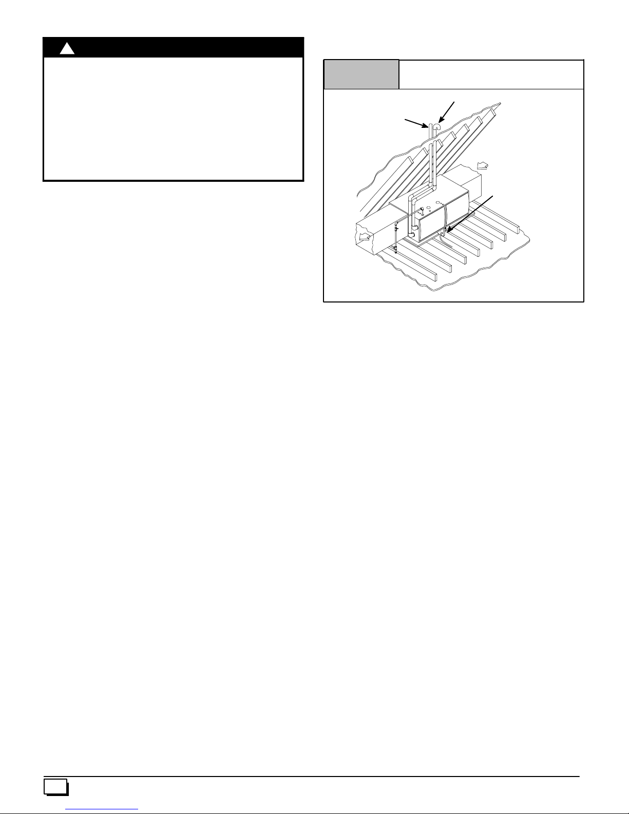
1. Refer to Figure 1 or Figure 2 for typical installation and
basic connecting parts required. Refer to Figure 3 for typical horizontal direct vent installation and basic connecting
parts required. Supply and return air plenums and duct are
also required.
2. If furnace is a replacement, it is usually best to install the furnace where the old one was. Choose the location or evaluate the existinglocation based uponthe minimum clearance
and furnace dimensions (Figure 4 ).
!
FROZEN AND BURST WATER PIPE HAZARD
FaiIure to protect against the risk of freezing may
result in property damage.
Special precautions MUST be made if installing
furnace in an area which may drop below freezing.
This can cause improper operation or damage to
equipment. If furnace environment hasthe potential
of freezing, the drain trap and drainline must be
protected. The use of electric heat tape or RV
antifreeze is recommended for these installations.
(See“Condensate Trap Freeze Protection Section”)
CAUTION
4
440 01 2021 01
Page 5
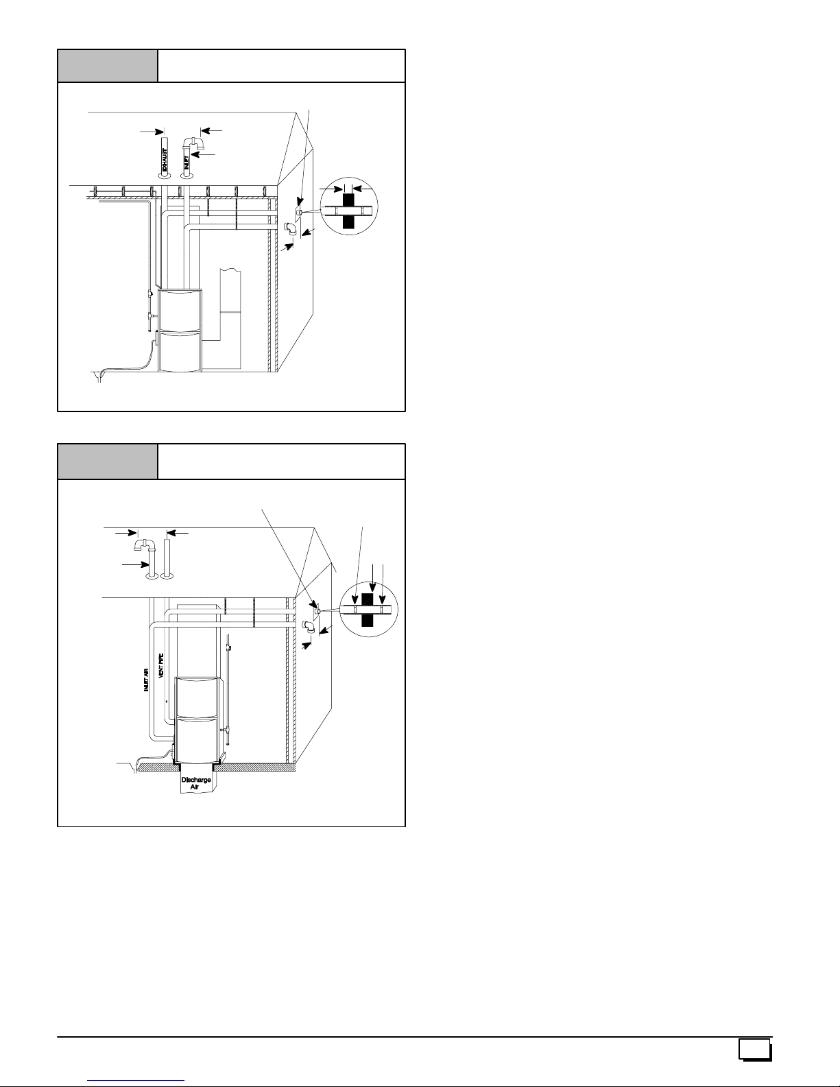
Figure 1
*8² Min.
20¢ Max.
in same
atmospheric
zone
VentPipes MUST be
supported
Horizontallyand
Vertically
*Increaseminimumfrom8²
below 0 °°°° F).
T y pical Upflow Installation
Aluminumornon--rustingshield recommended.
(SeeVentTermination Shielding fordimensions).
InletPipe
(notusedon
SinglePipe
model)
DISCHARGEAIR
² to18²²²² forcoldclimates(sustainedtemperatures
²²
Couplingon endsof
exhaust pipe. Total
pipe & coupling outside structure = 8²
*8² Min.
20¢ Max.
insameatmosphericzone
25--23--33
Figure 2 Typical Downflow Installation
InletPipe
(notusedon
SinglePipe
model)
VentPipes MUST
besupportedHorizontally and Vertically
* Increaseminimum from8 ²
below 0°°°°F).
See VentTermination
Shielding in VentSection.
*8² Min.
20¢ Max.insame
atmosphericzone
² to18²²²² forcold climates(sustained temperatures
²²
Coupling on inside
andoutsideofwallto
restrainvent pipe
8² Min.
*8² Min.
20¢ Max.
in same
atmosphericzone
25--23--33a
Installation Requirements
1. Install furnace level.
2. This furnace is NOT to be used for temporary heat of build-
ings or structures under construction.
3. Install furnace as centralized as practical with respect to the
heat distribution system.
4. Install the vent pipes as short as practical, and in accor-
dance to these instructions. (See Vent and Combustion
Air Piping section).
5. Maintain clearance for fire safety and servicing. A front
clearance of 24² is required for access to the burner, controls and filter. See clearance requirements in Figure 4.
6. Use a raised base for upflow furnace if the floor is damp or
wetattimes.
7. For downflow installations, non combustible subbase must
be used under the furnace unless installation is on a non
combustible floor surface. This requirement applies even
when a coil box or cabinet is used.
8. For horizontal installations, line contact is permissible only
between lines formed by intersection of back and two sides
of furnace jacket, and building joists, studs or framing.
9. Residential garage installations require:
· Burners and ignition sources installed at least 18² above
the floor.
· Located or physically protected from possible damage by
a vehicle.
10. Local codes may require a drain pan under the entire furnace and condensate trap when the furnace is installed in
attic application.
This furnace may be used for construction heat provided that all
the following conditions are met:
· The furnace is permanently installed with all electrical wir-
ing, piping, venting and ducting installed according to these
installation instructions. A return air duct is provided,sealed
to the furnace casing, and terminated outside the space
containing the furnace. This prevents a negative pressure
condition as created by the circulating air blower, causing a
flame rollout and/or drawing combustion products into the
structure.
· The furnace is controlled by a thermostat. It may not be “hot
wired” to provide heat continuously to the structure without
thermostatic control.
· Clean outside air is provided for combustion. This is to mini-
mize the corrosive effects of adhesives, sealers and other
construction materials. It also prevents the entrainment of
drywall dust into combustion air, which can cause fouling
and plugging of furnace components.
· The temperature of the return air to the furnace is main-
tained between 55° F(13° C) and 80° F(27° C) , with no eve-
ning setback or shutdown. The use of the furnace while the
structure is under construction is deemed to be intermittent
operation per our installation instructions.
· The air temperature rise is within the rated rise range on the
furnace rating plate, and the firing rate has been set to the
rating plate value.
· The filters used to clean the circulating air during the
construction process must be either changed or thoroughly
cleaned prior to occupancy.
· The furnace, ductwork and filters are cleaned as necessary
to remove drywall dust and construction debris from all
HVAC system components after construction is completed.
· Afterconstruction is complete, verify furnace operating con-
ditions including ignition, input rate, temperature rise and
venting according to these instructions.
440 01 2021 01
5
Page 6
!
WARNING
CARBON MONOXIDE POISONING HAZARD.
FaiIuretofollow this warning could resultindeathor
personal injury.
Do NOT operate furnace in a corrosive atmosphere
containing chlorine, f luorine or any other damaging
chemicals, which could shorten furnace life.
Refer to 3. Combustion & Ventilation Air section,
Contaminated Combustion Air for combustion air
evaluation and remedy.
Furnace Installation Considerations
The installation ofthe furnace for a given application will dictate the
position of thefurnace, the airflow, ductwork connections, vent and
combustion air piping. Consideration must be given to the follow ing:
Horizontal Furnace Installation
Figure 3
Vent
Pipe
T ypical Horizontal Installation
Inlet Pipe (not used on SinglePipe model)
Condensate
Trap
Condensate Trap and Drain Lines
The supplied condensate trap must be attached to the furnace
side panel on either the left or right side. For horizontal installations, the drain trap is vertically attached to the side panel below
the furnace. A minimum clearance of 6² below the furnace is required for the condensate trap. Downward slope of the condensate drain line from the condensate trap to the drain location must
be provided. Adequate freeze protection of the drain trap and the
drain line must be provided. See “CondensateDrainTrap”section
for further details.
Leveling
Proper leveling of the furnace must be provided to insure proper
drainage of the condensate from the furnace. The furnace must be
level to within
and downflow installations or top to bottom for horizontal installations.
1
/4² from front to back and fromside to side for upflow
Ventand Combustion Air Connections
On the Dual Certified furnace, the vent and combustion air pipes
attach to the furnace through the top panel for the upflow and horizontal installations. For the downflow installation, the vent and
combustion air pipes attach to the furnace through the alternate
locations on the furnace side panels.
Note: On the Direct Vent furnace, the vent pipe attaches to the furnace through the side panels. The combustion air pipe attaches to
the top panel or to the alternate location on the side panel.
On the Single Pipe furnace, the vent pipe attaches to the furnace
through the furnace side panels.
Note: Repositioning of the combustion blower is required for the
vent pipe connection to the furnace through the “right side” panel.
See “Vent and Combustion Air Piping” section for further details.
25--23--34
NOTE: 5² bottom clearance required for condensate trap.
This furnace can be installed horizontally in an attic, basement,
crawl s pace, alcove, or suspended from a ceiling in a basement or
utility room (See Figure 3). Do notinstall furnace on its back or in
the reverse airflow positions as safety control operation will be adversely affected.
If the furnace is to be suspended from the floor joists in a crawl
space or the rafters in an attic, it is necessary to use steel pipe
straps or an angle iron frame to rigidly attachthe furnace to prevent
movement. These straps should be attached to the furnace with
sheet metal screws and to the rafters or joists with bolts. The preferred method is to use an angle iron frame bolted to the rafters or
joists. (Takecaution to allowdoor panels to be removedfor maintenance)
If the furnace is to be installed in a crawl s pace, consult local
codes. A suitable concrete pad or blocks are recommended for
crawl space installation on the ground.
NOTE: 6² bottom clearance required for condensate trap.
Twenty four (24) inches between the front of the furnace and adja cent construction orother appliances MUSTbe maintainedfor ser vice clearance. (Thirty (30) inches is required to remove furnace).
Keep all insulating materials clear from louvered door. Insulating
materials may be combustible.
The horizontal furnaces may be installed directly on combustible
wood flooring or supports as long as all required furnace clearances are met. See Figure 3 .
This furnace MUST NOTbe installed directly on carpeting or tile or
other combustible material other than wood flooring or supports.
For horizontal installation over a finished living space. A field fabricated auxiliary drain pan with drain pipe is required to prevent
damage by overflow due to blocked condensate drain.
6
440 01 2021 01
Page 7
Figure 4
Uni
t
Dimensions and Clearances
F
AIR INTAKE
VENT
TOP
H
G
E
LEFT SIDE
TRAP (COUNTERFLOW)
GAS
VENT
AIR INTAKE
(ALTERNATE)
TRAP
UPFLOW/HORIZONTAL
1
2
/
4
1
/
13
4
7
1
/
8
THERMOSTAT
215/
8
24
413/
611/
16
ELECTRICAL
11/
4
11/
16
11
13
/
16
3111/
283/
16
297/
16
8
4
1913/
16
16
13/
8
7
241/
175/
16
111/
16
47/
8
Drawing is representative,
but some models may vary
D
C
BOTTOM
1
23
/
8
37/
8
ALL DIMENSIONS IN INCHES
Unit
Capacity
Cabinet Bottom Top
A B C D E F G H
*9MPT050F12 191/8175/821/8143/443/841/221/291/
*9MPT075F14 191/8175/821/8143/443/841/221/291/
*9MPT100J16 223/4211/4115/16183/443/841/225/8113/
*9MPT125L20 241/223
7
/
23 43/841/221/4121/
16
*9MPV050F12 191/8175/821/8143/443/841/221/291/
*9MPV075F12 191/8175/821/8143/443/841/221/291/
*9MPV100J20 223/4211/4115/16183/443/841/225/8113/
*9MPV125L20 241/223
7
/
23 43/841/221/4121/
16
* Dentoes Brand
A
B
FRONT
2
2
8
4
2
2
8
4
COMBUSTIBLE MATERIALS FOR ALL UNITS
MINIMUM CLEARANCES TO
REAR 0
FRONT (combustion air openings in
furnace and in structure)
Required For Service
ALL SIDES Of SUPPLY PLENUM 1²
SIDES 0
VENT 0
TOP OF FURNACE 1²
*30² clearance recommended forfurnaceremoval.
Horizontalposition: Line contactis permissibleonlybetween
linesformedby intersectionsof top and two sides of furnace
jacket,and building joists,studsor framing.
NOTE: Evaporator “A” coil drain pan dimensions may
vary from furnace duct opening size. Always consult
evaporator specifications for duct size requirements.
Furnace is designed for bottom return or side return.
Return air through back of furnace is NOT allowed.
1
1
/
4
7
2
913/
/
8
45/
16
3
/
2
8
11/
16
GAS
3
/
1
16
16
3311/
16
297/
273/
413/
16
11/
16
8
16
215/
8
175/
111/
7
16
16
7
4
/
8
281/
2
1
18
/
RIGHT SIDE
TRAP
(COUNTERFLOW)
ELECTRICAL
AIR INTAKE(ALTERNATE)
VENT
TRAP
UPFLOW/HORIZONTAL
215/
21/
131/
8
THERMOSTAT
24
2
3²
*24²
3
/
4
TYPE
40
4
4
17/
8
25--23--36b
440 01 2021 01
7
Page 8
3. Combustion & Ventilation Air
For Single Pipe Installation
(Non--Direct Vent)
!
CARBON MONOXIDE POISONING HAZARD
Failure to provide adequate combustion and
ventilation air could result in death or personal
injury.
Use methods described here to provide
combustion and ventilation air.
Furnaces require ventilation openings to provide sufficient air for
proper combustion and ventilation of flue gases. All duct or openings for supplying combustion and ventilation air must comply with
National Fuel Gas Code, NFPA54/ANSI Z223.1, 2002 (or current
edition) and applicable provisions of local building codes.
1. Section 8.3, Air for Combustion and Ventilation, of the Nation al Fuel Gas Code, National Fuel Gas Code (NFGC), ANSI
Z223.1--2002/NFPA 54--2002 in the U.S.,
2. Sections 7.2, 7.3, 7.5, 7.6, 7.7, and 7.8 of National Standard of
Canada, Natural Gas and Propane Installation Code
(NSCNGPIC), CSA B149.1--05 in Canada,
3. Applicable provisions of the local building code.
This furnace can NOT be c ommon vented or connected to any
type B, BW or L vent or vent connector,nor to any portion ofa factory--built or masonry chimney. Multistory venting i s NOT permitted.
If this furnace is replacing a previously common-vented furnace, it
may be necessary to resize the existing v ent and chimney to prevent oversizing problems for the other remaining appliance(s).
See “VentingandCombustionAir Check” in this section. This fur-
nace MUST be vented to the outside.
When the installation is complete, check that all appliances have
adequate combustion air and are v enting properly. See Venting
AndCombustionAirCheckin “5. GasVentInstallation” Section in
this manual.
WARNING
Outdoor Combustion Air Method
A space having less than 50 cubic feet per1,000 BTUH input rating
for all gas appliances installed in the space requires outdoor air for
combustion and ventilation.
Air Openings and Connecting Ducts
1. Total input rating for all non direct vent gas appliances
MUST be considered when determining free area of openings.
2. Connect ducts or openings directly to outside.
3. When screens are used to cover openings, they MUST be
no less than1/4² mesh.
4. The minimum dimension of rectangular air ducts MUST
NOT be less than 3².
5. When sizing grille or louver, use the free area of opening. If
free area is NOT stamped or marked on grill or louver, assume a 20% free area for wood and 60% for metal.
Confined Space Installation
NOTE: A confined space is defined as an area with less than 50
cubic feet per 1,000 BTUH input rating for all gas appliances
installed in the area.
Requirements
1. Provide confined space with sufficient air for proper combustion and ventilation of flue gases using horizontal or vertical ducts or openings.
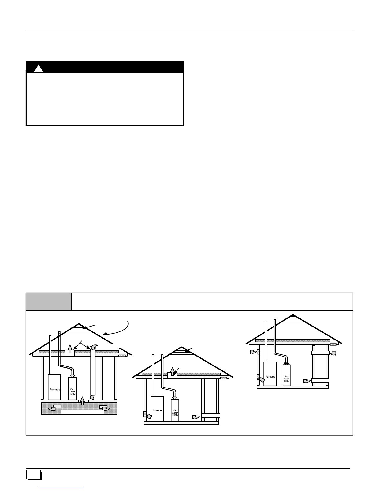
2. Figure 5 illustrate how to provide combustion and ventilation air. A minimum of two permanent openings, one inlet
and one outlet, are required.
a. One opening MUST commencewithin12² of the floor
and the second opening MUST commence within 12² of
the ceiling.
b. Size openings and ducts per Table 1.
Figure 5
Outside Air (This is O NLY a guide. Subject to codes of country having jurisdiction.)
This installation NOT approved in Canada
Gable Vent
Gas Vent
VentilatedAttic
TopAbove Insulation
Outlet Air (1)
VentilatedCrawl Space
Alternate Inlet Air (1)
Alternate Inlet Air (1)
Soffit Vent
Inlet
Air (1)
Gas Vent
c. Horizontal duct openings require 1 square inch of free
area per 2,000 BTUH (1,100 mm2/kW) of combined input
for all gas appliances in the space (see Table 1).
8
Gable Vent
VentilatedAttic
TopAbove Insulation
OutletAir (1)
Gas Vent
Outlet
Soffit Vent
Inlet
Air (2)
Outlet
Air (1)
Inlet
Air (1)
Minimum OneInlet and One OutletAir Supply is Required
May bein any Combination Shown
Inlet Air Opening Must be Within12² of floor
Outlet Air Opening Must be Within12² of ceiling
(1) 1 Square Inch per 4000 BTUH
(2) 1 Square Inch per 2000 BTUH
Inlet
Air (2)
Air (2)
d. Vertical duct openings or openings directly communicat-
ing with the outdoors require 1 square inch of free area
per 4,000 BTUH (550 mm
2
/kW) for combined input of all
gas appliances in the space (see Table 1).
440 01 2021 01
Page 9
3. One opening MUST be within 12² of the floor and the sec-
BTU
H
ond opening within 12² of the ceiling.
a. 1 sq. in of free area per 3,000 BTUH (700 mm
2
/kW) for
combined input of all gas appliances in the space (see
Table 1) and
b. not less than the sum of the areas of allvent connectors in
the space.
The opening shall commence within 12² of the top of the enclosure. Appliances shallhave clearances ofat least 1² from the sides
and back and 6² from the front. The opening shall directly communicate with the outdoors or shall communicate through a vertical or
horizontal duct to the outdoors or spaces (crawl or attic) that freely
communicate with the outdoors.
4. Size openings and ducts per Table 1.
a. Indoor openings that comply with the Indoor Combus-
tion Air Method below and
b. Outdoor openings located as required in the Outdoor
Combustion Air Method above and
c. Outdoor openings sized as follows.
1) Calculate the Ratio of all Indoor Space volume
divided by required volume for IndoorCombustion
Air Method.
2) Outdoor opening size reduction Factor is 1 minus
the Ratio in 1) above.
3) Minimum size of Outdoor openings shall be the size
required in Outdoor Combustion Air Method
above multiplied by reduction Factor.
5. Horizontal duct openings require 1 square inch of free area
per 2,000 BTUH of combined input for all gas appliances in
area (see Table 1).
6. Vertical duct openings or openings directly to outside require 1 square inch of free area per 4,000 BTUH for combined input of all gas appliances in area (see Table 1).
Table 1
Input
Rating
50,000 25sq.in. 16.7 sq. in. 12.5 sq. in. 4²
75,000 37.5 sq. in. 25sq. in. 18.75 sq. in. 5²
100,000 50sq.in. 33.3 sq. in. 25 sq. in. 6²
125,000 62.50 sq. in. 41.7 sq. in. 31.25 sq. in. 7²
EXAMPLE: Determining Free Area
Furnace
100,000
Furnace
100,000
Unconfined Space Installation
!
Free Area
TwoHorizontal Ducts
(sq. in./2,000 BTUH)
Water Heater
+
+
30,000
Water Heater
30,000
=
=
WARNING
Minimum FreeAreaRequired for Each Opening or Duct to Outdoors
TwoVerticalDuctsor
(sq. in./4,000BTUH)
(sq. in./3,000 BTUH)
Total Input
(130,000 ¸ 4,000)
Total Input
(130,000 ¸ 2,000)
Single Opening
==32.5 Sq. In. Vertical
65 Sq. In. Horizontal
An unconfined space is defined as an area having a minimum volume of 50 cubic feet per 1,000 Btuh total input rating for all gas appliances in area. Refer to Table 2 for minimum area required.
Openings
CARBON MONOXIDE POISONING HAZARD
Failure to supply additional air by means of
ventilation grilles or ducts could result in death or
personal injury.
An unconfined space or homes with tight
construction may not have adequate air infiltration
for proper combustion and ventilationofflue gases.
Most homes will require additional air.
Rd Duct
(sq. in./4,000 BTUH)
MINIMUM SPACE VOLUME FOR 100% COMBUSTION AND VENTILATIONAIR FROM INDOORS (ft3)
Table 2
ACH
0.60 1,050 1,400 1,750 1,250 1,875 2,500 3,125
0.50 1,260 1,680 2,100 1,500 2,250 3,000 3,750
0.40 1,575 2,100 2,625 1,875 2,813 3,750 4,688
0.30 2,100 2,800 3,500 2,500 3,750 5,000 6,250
0.20 3,150 4,200 5,250 3,750 5,625 7,500 9,375
0.10 6,300 8,400 10,500 7,500 11,250 15,000 18,750
0.00 NP NP NP NP NP NP NP
NP = Not Permitted
Table 2 Minimum Space Volumes were determined by using the
following equations from the National Fuel Gas Code ANSI
Z223.1/NFPA 54--2002, 8.3.3.2:
440 01 2021 01
30 40 50 50 75 100 125
Other Than Fan-Assisted Total
(1,000’sBtuh)
Fan-assisted Total
(1,000’sBtuh)
1. For other than fan--assisted appliances such as a draft
hood--equipped water heater,
9
Page 10
(
1000 Btu / hr
(
1000 Btu / hr
I
I
other
fan
)
)
3
Volume
2. For fan--assisted appliances such as this furnace,
Volume
If:
The following requirements apply to the Standard Method and to
the Known Air Infiltration Rate Method.
other
fan
= combined input of all other than fan--assisted
I
other
appliances in Btu/hr
I
= combined input of all fan--assisted appliancesin Btu/hr
fan
ACH = air changes per hour (ACH shall not exceed 0.60.)
21 ft
=
ACH
3
15 ft
=
ACH
· Adjoining rooms can be considered part of a space, if there
are no closable doors between rooms.
· An attic or crawl space may be considered a space that freely
communicateswith the outdoors provided there are adequate
ventilation openings directly to outdoors. Openings MUSTremain open and NOT have any means of being closed off. Ventilation openings to outdoors MUST be at least 1 square inch
of free area per 4,000 BTUH of total input rating for all gas appliances in the space.
· Combining s paces on the same floor level. Each opening
shall have a free area of at least 1² 2/1,000 BTUH (2,000
mm2/kW) of the total input rating of all gas appliances in the
space, but not less than 100 in2 (0.06 m2). Once opening
shall commence within 12² (300 mm) of the ceiling and the
second opening shall commence within 12² (300 mm) of the
floor. The minimumdimension of air openings shall be atleast
3² (80 mm).
· Combining spaces on different floor levels. The volumes of
spaces on different floor levels shall be considered communicating spaces if connected by one or more permanent openings in doors or floors having a free area of at least 2² 2/1,000
Btuh (4,400 mm2/kW) of total input rating of all gas appliances.
· In spaces that use the Indoor Combustion Air Method, in-
filtration should be adequate to provide air for combustion,
ventilation and dilution of flue gases. However, in buildings
with unusually tight construction, additional air MUST be provided using the methods described in section titled Outdoor
Combustion Air Method:
· Unusually tight construction is defined as Construction with
1. Walls and ceilings exposed to the outdoors have a continuous, sealed vapor barrier. Openings are gasketed or
sealed and
2. Doors and openable windows are weather stripped and
3. Other openings are caulked or sealed. These include
joints around window and door frames, between sole
plates and floors, between wall--ceiling joints, between
wall panels, at penetrations for plumbing, electrical and
gas lines, etc.
Ventilation Air
Some provincial codes and local municipalities require ventilation
or make--up air be brought into the conditioned space as replacement air. Whichever method is used, the mixed return air temperature across the heat exchanger MUST not fall below 60° so that
flue gases will not condense excessively in the heat exchanger.
Excessive condensation will shorten the life of the heat exchanger
and possibly void your warranty.
Venting and Combustion Air Check
The following information is s upplied to allow the installer to make
adjustments to the setup of existing appliances, IF REQUIRED,
based on good trade practices, local codes, and good judgement
of the installer. Manufacturer does NOT take responsibility for
modifications made to existing equipment.
NOTE: If this installation replaces an existing furnace from a
commonly vented system, the original venting system may no longer be sized to properly vent the attached appliances. An improperly sized venting system may cause the formation of condensate
in the vent and the leakage or spillage of vent gases. To make sure
there is adequate combustion air for all appliances, MAKE THE
FOLLOWING CHECK.
!
CARBON MONOXIDE POISONING HAZARD
Failure to follow the steps outlined below for each
applianceconnected totheventing systembeingplaced
into operation, could result in carbon monoxide
poisoning or death:
Thefollowingstepsshall be followed for each appliance
connected to the venting system being placed into
operation, while all other appliances connected to the
venting system are not in operation:
1. Seal any unused openings in the venting system.
2. Inspect the venting system for proper size and horizontal
pitch, as required in the National Fuel Gas Code, ANSI
Z223.1/NFPA 54 or CSA B149.1, Natural Gas and PropaneInstallationCodeand these instructions. Determine
that there is no blockage or restriction, leakage, corrosion
and other deficiencies which could cause an unsafe condition.
3. As far as practical, close all building doors and windows
and all doors between the space in which the appliance(s)
connected to the venting system are located and other
spaces of the building.
4. Close fireplace dampers.
5. Turn on clothes dryers and any appliance not connected
to the venting system. Turn on any exhaust fans, such as
range hoods and bathroom exhausts, so they are operating at maximum speed. Do not operate a summerexhaust
fan.
6. Follow the lighting instructions. Place the appliance being
inspected into operation. Adjust the thermostat so appliance is operating continuously.
7. Test for spillage from draft hood equipped appliances at
the draft hoodrelief opening after5 minutesof main burner
operation. Use the flame of a match or candle. (Figure 6)
8. If improper venting is observed, during any of the above
tests, the venting system must be corrected in accor-
dance with the National Fuel Gas Code, ANSI
Z223.1/NFPA 54 and/or CSA B149.1, Natural Gas and
Propane Installation Code.
9. After it has been determined that each appliance connected to the venting system properly vents when tested
as outlined above, return doors, windows, exhaust fans,
fireplace dampers and any other gas--fired burning appliance to their previous conditions of use.
WARNING
10
440 01 2021 01
Page 11
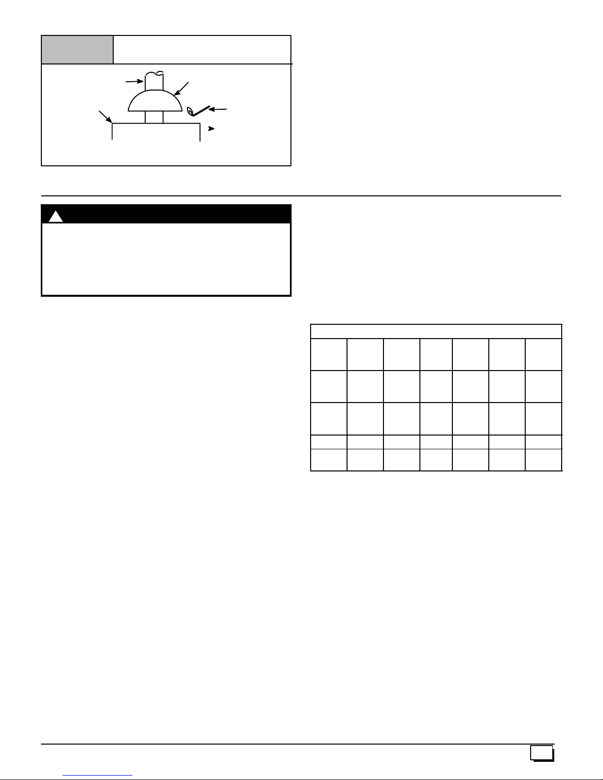
Figure 6
Vent Check
For Two Pipe Installation
(Direct Vent)
Vent Pipe
Typical Gas
Water Heater
If flame pulls towards draft hood, this indicates
sufficient venting.
Draft Hood
Match
This furnace can NOT be c ommon vented or connected to any
type B, BW or L vent or vent connector,nor to any portion ofa facto ry--built or masonry chimney. If this furnace is replacing apreviously common-vented furnace, it may be necessary to resize the
existing vent and chimney to prevent oversizing problems for the
other remaining appliance(s). See “Venting and Combustion Air
Check” in this section. This furnace MUST be v ented to the out-
side.
4. Vent and Combustion Air Piping
!
WARNING
CARBON MONOXIDE POISONING HAZARD.
Failure to properly vent this furnace could result in
death or personal injury.
Use methods described here to provide combustion
and ventilation air.
Dual Certified (*9MPT & *9MPV Models)
Direct or Non-Direct Vent
This furnace is certified as a CategoryIVfurnace. This furnace can
be installed as a direct vent furnace using outside air for combustion or the furnace can use air from inside the s tructure for combustion. The INLET air pipe is optional. If combustion air comes from
inside the structure, adequate make up air MUST be provided to
compensate for oxygen burned. See Confined Space Installa-
tion in the Combustion and Ventilation Air chapter. If c ombus tion air is drawn from outside the structure, it MUST be taken from
the same atmospheric pressure zone as the vent pipe.
Contaminated Combustion Air
Installations in certain areas or types of structures will increase the
exposure to chemicals or halogens that may harm the furnace.
The following areas or types of structures may contain or have exposure to the substances listed below. The installation must be
evaluated carefully as it may be necessary to provide outside air
for combustion.
· Commercial buildings.
· Buildings with indoor pools.
· Furnaces installed in laundry rooms.
· Furnaces installed i n hobby or craft rooms.
· Furnaces installed near chemical storage areas.
· Permanent wave solutions for hair.
· Chlorinated waxes and cleaners.
· Chlorine based swimming pool chemicals.
· Water softening chemicals.
· De--icing salts or chemicals.
· Carbon tetrachloride.
· Halogen type refrigerants.
· Cleaning solvents (such as perchloroethylene).
· Printing inks, paint removers, varnishes, etc.
· Hydrochloric acid.
· Sulfuric Acid.
· Solvent cements and glues.
·
· Masonry acid washing materials.
Vent and Combustion Air Piping Guidelines
This furnace is approved for venting with Schedule 40 PVC,
CPVC, ABS, Cellular Core pipe fittings and SDR--26 PVC.
Materials
ABS D1527 __ F628
PVC D1785 D2241 F891
CPVC F441 F442 -- -- F438 -- -- F493
ABS to
PVC
NOTE: 1) In Canada, all pipe, fittings & cements must conform to
applicable CSA standards or to local codes having jurisdiction.
the specific venting material.
vent cement that meets the requirements of ASTM D3138.
cementing plastic pipe and fittings.
NOTE: In order to create a seal that allows future removal of pipe,
RTVsealant MUSTbe usedonthe inletpipewhere it joins to the
furnace.
NOTE: All vent piping MUSTbeinstalledincompliancewithlocal
codes or ordinances, these instructions, good trade practices, and
codes of country having jurisdiction.
1. Determine the best routing and termination for the vent pipe
2. Determine the size required for the vent pipe and air inlet
3. Loosely assemble all venting parts without adhesive (pipe
4. Furnace shall be installed so as to prevent the accumulation
Antistatic fabric softeners for clothes dryers.
Applicable ASTM Standards for Vent Materials
Sch. 40
Pipe
-- -- -- -- -- -- -- -- -- -- D3138
2) Only use solvent cements that are marked for use with
3) ABS to PVC transition joints REQUIRE a special sol-
4) Refer to ASTM D2855 for general procedure to use for
and air inlet pipe by referring to all of the instructions and
guidelines in this Section.
pipe.
joint cement) for correct fit before final assembly.
of condensate.
SDR
Pipe
Cell
Core
Pipe
Fittings Primer
D2468
&
D2661
D2466
&
D2665
-- -- D2235
F656 D2564
Solv.
Cement
440 01 2021 01
11
Page 12
5. Use of vertical piping is preferred because there will be
some moisture in the flue gases that may condense as it
leaves the vent pipe.
6. The vertical vent pipe MUSTbe supported so that no weight
is allowed to rest on the combustion blower.
7. Exhaust vent piping or air inlet piping diameter MUST NOT
be reduced.
8. All exhaust vent piping from the furnace to termination
MUST slope upwards. A minimum of
required to properly return condensate to the furnace drain
system.
9. Use DWV type long radius elbows whenever possible, as
they provide for the minimum slope on horizontal runs and
they provide less resistance in the vent system. If DWV elbows cannot be used, use two, 45° elbows when possible.
On horizontal runs the elbows can be slightly misaligned to
provide the correct slope.
10. All horizontal pipe runs MUST be supported at least every
five feet with galvanized strap or other rust resistant material. NO sags or dips are permitted.
11. All vertical pipe runs MUST be supported every six feet
where accessible.
12. The maximum pipe length is 40¢ total in the inlet or outlet
side of the system. Up to five,90° elbows can be used on the
inlet or the outlet. With the Concentric Vent TerminationKits
(NAHA001CV or NAHA002CV), the maximum pipe length
is 35¢ with490° elbows. If more elbows are required, reduce
the length of both the inlet and exhaust pipes 5¢ for each
additional elbow used. (See Table 3 or Table 4).
13. The minimum pipe run length is 2¢.
14. The piping can be run in the same chase or adjacent to supply or vent pipe for water supply or waste plumbing. It can
also be run in the same chase with a vent from another 90+
furnace.
NOTE:InNO case can the piping be run in a chase where
temperatures can exceed 140° F. or where radiated heat
from adjacent surfaces would exceed 140° F.
15. The vent outlet MUST be installed to terminate in the same
atmospheric pressure zone as the combustion air inlet.
16. The vent system can be installed in an existing unused
chimney provided that:
1
/4² per foot of run is
· Both the exhaust vent and air intake run the length of the
chimney.
· No other gas fired appliance or fireplace (solid fuel) is
vented into the chimney.
· The top of the chimney MUST be sealed flush or crowned
up to seal against rain or melting snow so ONLYthe piping
protrudes.
· The termination clearances shown in Figure 7 are main-
tained.
17. Furnace applications with vertical vents requiring vent diameter increaser fittings must have increaser fittings
installed in vertical portion of the vent. Condensate will be
trapped in the vent if the vent diameter is increased prior to
having an elbow turned upward. This could cause nuisance
tripping of the pressure switch.
Combustion Air and VentPiping Insulation
Guidelines
NOTE: Use closed cell, neoprene insulation or equivalent. If Fiberglass or equivalent insulation is used it must have a vapor barrier.
UseRvaluesof7upto10¢, R--11if exposure exceeds 10¢. If Fiber-
glass insulation is used, exterior to the structure, the pipe MUST
be boxed in and sealed against moisture.
1. When the vent or combustion air pipe height above the roof
exceeds 30², or if an exterior vertical riser is used on a horizontal vent to get above snow levels, the exterior portion
MUST be insulated.
2. When combustion air inlet piping is installed above a suspended ceiling, the pipe MUST be insulated with moisture
resistant insulation such as Armaflex or other equivalent
type of insulation.
3. Insulate combustion air inlet piping when run in warm, humid spaces.
Sizing Combustion Air and Vent Pipe
Consult Table 3 or Table 4 to select the proper diameter exhaust
and combustion air piping. Exhaust and combustion air piping is
sized for each furnace Btuh size based on total lineal vent length
(on inlet or outlet side), and number of 90° elbows required.
1. Double Pipe Installation--If installing as a direct--vent ap-
pliance, consult Table 4 to select the proper diameter exhaust and combustion air piping. Exhaust and combustion
air piping is sized for each furnace Btuh size based on total
lineal vent length (on inlet oroutlet side), and number of 90°
elbows required.
2. Single Pipe Installation--If installing as a non--direct vent
appliance, (single outlet pipe and no inlet pipe) refer to
Table 3. The table shows the maximum number of elbows
allowed with any given pipe diameter and length of run.
3. Use of Elbows--Two 45° elbows can be substituted for one
90° elbow. The elbow or elbows used for vent termination
outside the structure AREcounted, including elbows needed to bring termination above expected snow levels.
Table 3
50,000 & 75,000 Btuh Furnaces
40¢¢¢¢ & (5) 90° elbows with 2² PVC pipe
40¢¢¢¢ & (5) 90° elbows with 3² PVC pipe
40¢¢¢¢ & (5) 90° elbows with 3² PVC pipe
Elbows are DWV Long Radius Type for 2² and 3² vents.
If more than five elbows are required, reduce the length of
both the inlet and exhaust pipes 5¢ foreach additional elbow
used.
NOTE: It is allowable to use larger diameter pipe and fitting than
shown in the tables but not smaller diameters than shown.
Table 4
50,000 & 75,000 Btuh Furnaces
40¢¢¢¢ & (5) 90° elbows with 2² PVC pipe
40¢ & (5) 90° elbows with 3² PVC pipe
40¢ & (5) 90° elbows with 3² PVC pipe
Elbows are DWV Long Radius Type for 2² and 3² vents.
If more than five elbows are required, reduce the length of
both the inlet and exhaust pipes 5¢ for each additional elbow
used.
*Feetof pipe is whichever pipe run is the longest, either inlet
or outlet side.
Pipe Diameter Table
Single Piping ONLY
100,000 Btuh Furnace
125,000 Btuh Furnace
Pipe Diameter Table
Dual Piping ONLY
75,000 Btuh Furnaces
100,000 Btuh Furnace
125,000 Btuh Furnace
12
440 01 2021 01
Page 13

For “Concentric Termination Kit” Venting table, see
“Section 11” in this manual.
VentTerminationClearances
!
CARBON MONOXIDE POISONING AND FIRE
HAZARD.
Failure to properly vent this furnace could result in
death, personal injury and/or property damage.
Inlet and outlet pipes may NOT be vented directly
above each other.
WARNING
1. Determine termination locations based on clearances specified in following steps andas shownin Figure 7, Figure 8,
Figure 20, through Figure 27.
For “Concentric Termination Kit” clearances, see Figure 30,
Figure 31, Figure 32, Figure 33 and Figure 3 4 in “Section 10”
in this manual.
2. This furnace is Dual Certified and can be installed as a
single pipe appliance (all combustion from inside the structure) or asa directvent appliance where all combustionair is
taken from outside the s tructure.
3. For Single Pipe installation refer to Figure 8 for vent termination c learances.
4. For Direct Vent installation, refer to Figure 7 for vent termination.
440 01 2021 01
13
Page 14
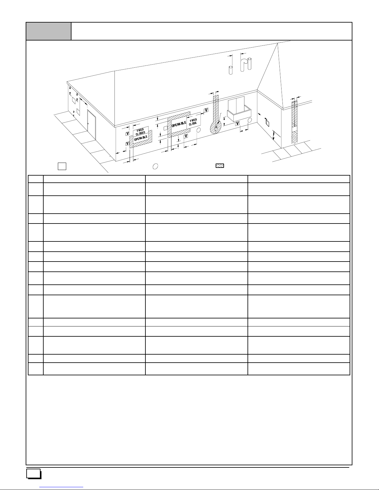
Figure 7
Direct Vent Te rmination Clearance
X
N
Y
Y
D
E
V
B
V
O
C
F
V
VENT TERMINAL
Item Clearance Description Canadian Installation (1)
A Clearance abovegrade, veranda, porch, deck, balcony, or
anticipated snow level
B Clearance toa window or door that may be opened 6² (15cm) forappliances £ 10,000 BTUH (3kW), 12² (30
C Clearance to a permanently closed window
D Vertical clearance to a ventilated soffit locatedabovethe
terminal within a horizontal distance of 2¢ (61cm) from the
centerline of the terminal
E Clearance to an unventilated soffit
F Clearance toan outside corner
G Clearance to an inside corner
H Clearance to each side of thecenterline extendedabove
electrical meter or gas service regulator assembly
I Clearance to service regulator vent outlet 3¢ (91 cm)
J Clearance to non--mechanical air supply inlet tobuilding or
the combustion air inlet toany other appliance
K Clearance toa mechanical air supply inlet 6¢ (1.83 m) 3¢ (91cm) aboveifwithin 10¢ (3m horizontally)
L Clearance under a veranda, porch,deck, orbalcony 12² (30cm) +
M Clearance to each sideof the centerline extended above or
below vent terminal of the furnace to a dryer or water heater
vent, or other appliance’s direct ventintake or exhaust.
N Clearance from a plumbing vent stack 3¢ (91 cm) 3¢ (91 cm)
O Clearance above a pavedsidewalk or paveddriveway located
on public property.
(1.) In accordance with thecurrentCSA B149.1, Natural Gas and Propane Installation Code
(2.) In accordance with thecurrent ANSI Z223.1/NFPA 54, National Fuel GasCode
#18² (46cm) aboveroof surface
+ Permittedonly if veranda, porch, deck, or balcony is fully open ona minimum oftwo sides beneath the floor.
B
B
V
B
B
X
AIR SUPPLYINLET
12² (30cm) # 12² (30 cm)
cm) for appliances > 10,000Btuh(3 kW) and £ 100,000 Btuh
(30kW), 36² (91 cm) forappliances > 100,000Btuh (30 kW)
* *
* *
* *
* *
* *
3¢ (91 cm) within15¢ (4.5 m) abovethe meter/regulator
assembly
6² (15 cm) for appliances £ 10,000 BTUH (3kW), 9² (23 cm)
for appliances > 10,000Btuh (3 kW) and £ 100,000 Btuh (30
kW) and £ 50,000 Btuh (15 kW), 12² (30 cm) forappliances
> 50,000Btuh(15 kW)
12² (30cm) 12² (30cm)
7¢ (2.13 m) 7¢ (2.13 m)
B
X
J
A
H
I
L
AREA WHERE TERMINAL IS NOT PERMITED
X
G
V
K
6² (15cm) forappliances £ 10,000 BTUH (3kW), 9² (23cm)
for appliances > 10,000Btuh (3 kW) and £ 50,000Btuh (15
kW), 12² (30 cm) for appliances > 50,000 Btuh(15 kW)
3¢ (91 cm) within15¢ (4.5 m) above themeter/regulator
assembly
A
U.S. Installation (2)
*
6² (15 cm) for appliances £ 10,000 BTUH (3kW), 9² (23 cm)
for appliances > 10,000Btuh (3 kW) and £ 50,000 Btuh (15
kW), 12² (30 cm) for appliances > 50,000Btuh(15 kW)
*
M
V
25--24--65--2
* Forclearancesnot specifiedin ANSIZ223.1/NFPA 54orCSAB149.1, clearancesshallbe inaccordance withlocal installation codesand therequirements ofthe gassupplier andthemanufacture’sinstallation
instructions.
** A vent shall not terminate directly above a sidewalk or paved driveway thatislocated between two single family dwellingsand serves both dwellings.
Notes:
1. The vent forthis appliance shall notterminate
a. Over public walkways; or
b. Nearsoffitvents or crawl space vents or other areas where condensate or vapor could create a nusiance or hazard orproperty damage;or
c. Where condensate vapor could cause damageor could be detrimental to the operation ofregulators, relief valves, or otherequipment.
2. Whenlocatingvent terminations,considerationmustbe given to prevailingwinds, location,andother conditions which may cause recirculation of the combustion products ofadjacent vents.
Recirculation can cause poor combustion, inlet condensate problems, and accelerated corrosion of the heat exchangers.
14
440 01 2021 01
Page 15
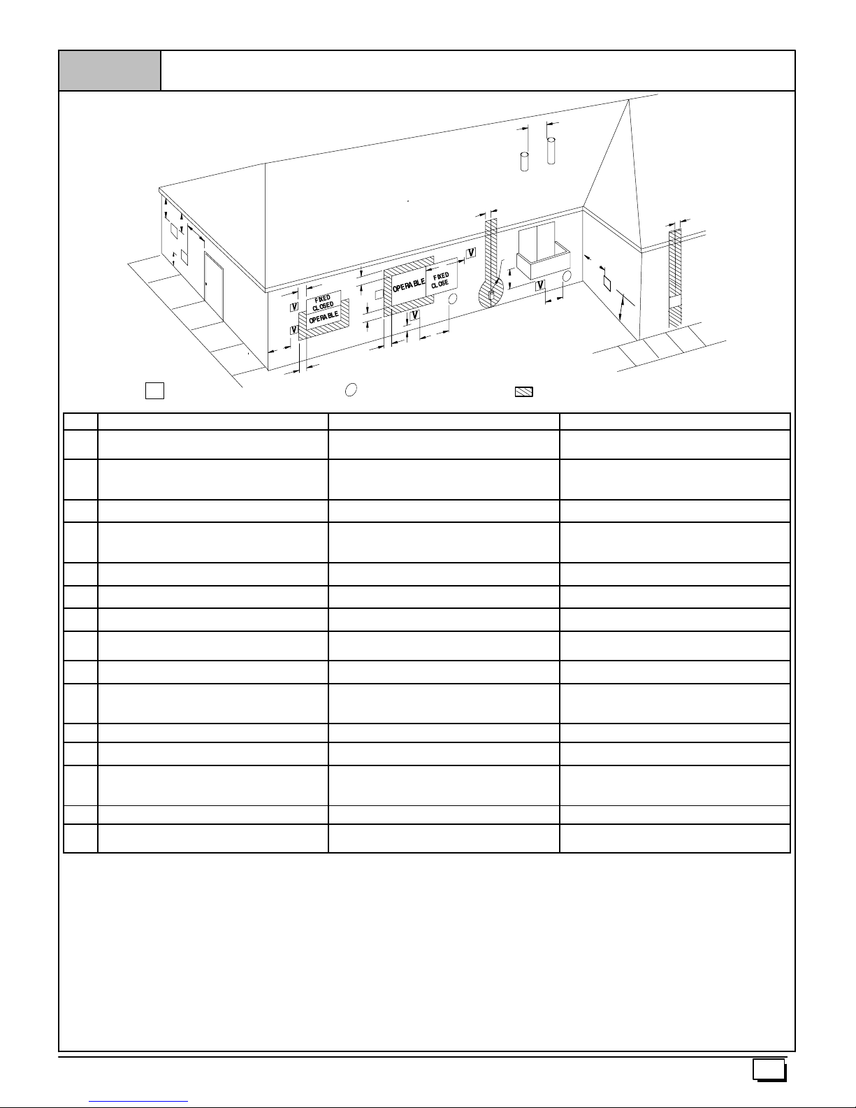
Figure 8
Other than Direct Vent Termination Clearance
N
Y
Y
D
E
V
B
O
V
C
F
B
V
VENT TERMINAL
Item Clearance Descriptions Canadian Installation (1)
A Clearance abovegrade, veranda, porch, deck, balcony, or
anticipated snow level
B Clearance toa window or door that may be opened 6² (15cm) forappliances £ 10,000 BTUH (3kW), 12² (30
C Clearance to a permanently closed window
D Vertical clearance to a ventilated soffit locatedabovethe
terminal within a horizontal distance of 2¢ (61cm) from the
centerline of the terminal
E Clearance to an unventilated soffit
F Clearance toan outside corner
G Clearance to an inside corner
H Clearance to each side of thecenterline extendedabove
electrical meter or gas service regulator assembly
I Clearance to service regulator vent outlet 3¢ (91 cm)
J Clearance to non--mechanical air supply inlet tobuilding or
the combustion air inlet toany other appliance
K Clearance toa mechanical air supply inlet 6¢ (1.83 m) 3¢ (91cm) aboveifwithin 10¢ (3m horizontally)
L Clearance under a veranda, porch,deck, orbalcony 12² (30cm) +
M Clearance to each sideof the centerline extended above or
below vent terminal of the furnace to a dryer or water heater
vent, or other appliance’s direct ventintake or exhaust.
N Clearance from a plumbing vent stack 3¢ (91 cm) 3¢ (91 cm)
O Clearance above a pavedsidewalk or paveddriveway located
on public property.
(1.) In accordance with thecurrentCSA B149.1, Natural Gas and Propane Installation Code
(2.) In accordance with thecurrent ANSI Z223.1/NFPA 54, National Fuel GasCode
#18² (46cm) aboveroof surface
+ Permittedonly if veranda, porch, deck, or balcony is fully open ona minimum oftwo sides beneath the floor.
B
V
B
B
X
AIR SUPPLYINLET
12² (30cm) # 12² (30 cm)
cm) for appliances > 10,000Btuh(3 kW) and £ 100,000 Btuh
(30kW), 36² (91 cm) forappliances > 100,000Btuh (30 kW)
* *
* *
* *
* *
* *
3¢ (91 cm) within15¢ (4.5 m) abovethe meter/regulator
assembly
6² (15 cm) for appliances £ 10,000 BTUH (3kW), 12² (30
cm) for appliances > 10,000Btuh(3 kW) and £ 100,000 Btuh
(30kW), 36² (91 cm) forappliances > 100,000Btuh (30 kW)
* *
7¢ (2.13 m) 7¢ (2.13 m)
B
X
J
A
H
I
L
X
G
V
K
AREA WHERE TERMINAL IS NOT PERMITED
4¢ (1.2m)belowor to the side of the opening. 1¢ (30 cm)
above theopening.
3¢ (91 cm) within15¢ (4.5 m) above themeter/regulator
assembly
A
*
4¢ (1.2m)belowor to the side ofopening:1¢ (30 cm) above
opening.
*
M
V
25--24--65--2
U.S. Installation (2)
* For clearances not specifiedin ANSI Z223.1/NFPA 54 orCSA B149.1, clearances shall be inaccordance with local installation codes and therequirements ofthe gas supplier and the manufacture’s
installation instructions.
** A vent shall not terminate directly above a sidewalk or paved driveway thatislocated between two single family dwellingsand serves both dwellings.
Notes:
1. The vent forthis appliance shall notterminate
a. Over public walkways; or
b. Nearsoffitvents or crawl space vents or other areas where condensate or vapor could create a nusiance or hazard orproperty damage;or
c. Where condensate vapor could cause damageor could be detrimental to the operation ofregulators, relief valves, or otherequipment.
2. Whenlocatingvent terminations,considerationmustbe given to prevailingwinds, location,andother conditions which may cause recirculation of the combustion products ofadjacent vents.
Recirculation can cause poor combustion, inlet condensate problems, and accelerated corrosion of the heat exchangers.
440 01 2021 01
15
Page 16
CondensateDrain Trap
This furnace removes both sensible and latent heat from the products of combustion. Removal of the latent heat results in condensation of the water vapor. The condensate is removed from the
furnace through the drains in the plastic transition and the vent fitting. The drains connect to the factory installed internally mounted
condensate drain trap on the left or right side of the furnace.
The startup of a new furnace will involve a cycle or two of the furnace to properly prime the condensate trap with water. Until the
trap is fully primed, some condensate will be pulled into the combustion blower. The furnace may cycleon the pressure switch connected to the plastic transition box due to condensate buildup.
After the trap is primed, the condensate will start draining from the
furnace. The combustion blower will clear out any remaining condensate in the blower housing through the vent fitting downstream
of the blower. Note that the condensate trap can also be primed by
pouring water into the
hose from either the gutter or the white PVC Tee Trap.Using a fun nel pour eight (8) ounces of water into
flow through the drain hose and into the condensate drain trap.
This will prime both the vent and the transition sides of the trap.Reconnect the
gutter or the PVC Tee Trap.
The condensate drain trap supplied with the furnace MUST be
used. The drain connection on the condensate drain trap is sized
3
/4² PVC or CPVC pipe, however alternate1/2² CPVC (nominal
for
5
/8² O.D.) or vinyl tubing with a minimum inner diameter (I.D.) of
5
/8² may also be used, as allowed by local codes. Alternate drain
pipes and hoses may be used as allowed by local codes.
The drain line must maintain a
the drain.1/4² per foot is recommended. Installation of an overflow
line is recommended when the1/4² per foot slope to the condensate drain cannot be maintained. See Figure 18 for proper routing
and installation of the overflow.
DO NOT trap the drain line in any other location than at the condensate drain trap supplied with the furnace.
If possible, DO NOT route the drain line where it may freeze. The
drain line must terminate at an inside drain to prevent freezing of
the condensate and possible property damage.
1
/2² ID drain hose to the original component, either the
1
/2² drain hose. Remove the1/2² ID drain
1
/2² ID drain hose.Water will
1
/4² per footdownward slope toward
1. A condensate sump pump MUST be used if required by lo-
cal codes, or if no indoor floor drain is available. The condensate pump must be approved for use with acidic
condensate.
2. A plugged condensate drain line or a failed condensate
pump will allow condensate to spill. If thefurnace is installed
where a condensate spill could cause damage, it is recommended that an auxiliary safety switch be installed to prevent operation of the equipment in the event of pump failure
or plugged drain line. If used, an auxiliary safety switch
should be installed in the R c ircuit (low voltage) ONLY.
3. If the auxiliary switch in the condensate pump is used, the
furnace may shut down due to a blocked condensate line or
failed pump. To prevent frozen water pipes see the “Frozen
Water Pipe Hazard” section on Page 4 of this manual.
!
CAUTION
FROZEN AND BURST WATER PIPE HAZARD
Failure to do so may result in burst water pipes,
serious property damage.
If a condensate pump is installed, a plugged
condensate drain or a failed pump may cause the
furnace to shut down. Do not leave the home
unattended during freezing weather without turning
off water supply and draining water pipes or
otherwiseprotectingagainsttheriskof frozenpipes.
Condensate Drain Trap Freeze Protection
Special precautions MUST be made if installing furnace in an area
which may drop below freezing. This can cause improper operation or damage to the equipment. If the the furnace environment
has the potential of freezing, the drain trap and drain line must be
protected. Use 3 to 6 watt per foot at 115volt, 40° F self--regulating
shielded and waterproof heat tape. Wrap the drain trap and drain
line with the heat tape and secure with the ties. Follow the heat
tape manufacturer’s recommendations. Prime the trap before furnace operation.
16
440 01 2021 01
Page 17
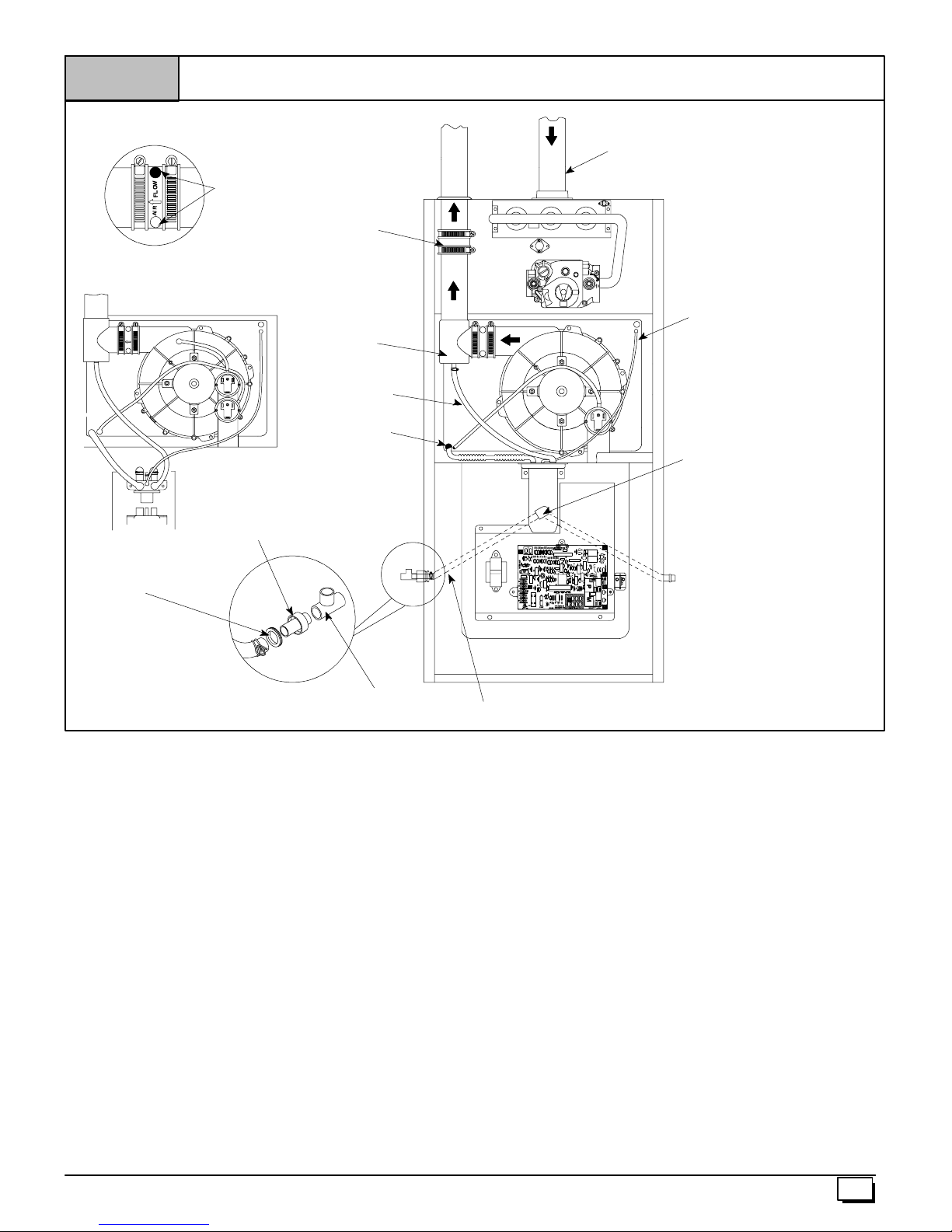
Figure 9
Upflow Installations Top Vent
Vent Drain
&Clamps
Dual Pressure Switch Detail
FLOW
AIR
Casing Grommet
Black Rubber
5
/
²
² ID
²²
8
(Loose partsbag)
Plastic Caps (2)
Yellowor black
Coupling & Clamps
(Optional)
DrainTee
Drain Tube
Black Rubber
1
/
²
² ID&Clamps
²²
2
Drain Tube
Corrugated
5
Drain ConnectorBlack PVC
3
/
²
² PVC X1/
²²
4
(Loose partsbag)
²
² CPVC
²²
2
/
²
² ID&Clamps
²²
8
EXHAUST
ON
On Some Models
ONLY
Single Pressure Switch
ReliefTube
Black Rubber
StreetElbow
1
/
²
² CPVC
²²
2
(Loose partsbag)
3
/
²
² ID
²²
16
INLET
V
E
N
T
IN
OFF
Drain LineVent Tee
1
/
²
² CPVC (Field supplied)
²²
2
3
/
²
² PVC or
²²
4
Drain TubeBlack Rubber5/
Cut lengthtofit (Loose parts bag)
²
² ID & Clamps,
²²
8
25--24--67
Upflow Installations Top Vent (See Figure 9)
Remove plug from the sideof the furnace casing where Drain Tube
will exit.
5
Install casing grommet (black rubber
/8² ID grommet -- in loose
parts bag)
1
Install the
Install the black PVC tube connector (
/2² CPVC street elbow on discharge of Trap
3
/4² PVC x1/2² CPVC from
loose parts bag) as shown in the illustration above.
5
Cut the black Drain Tube (
/8² ID -- in loose parts bag) to length to
fit between Trap and tube connector through grommet.
Clamp both ends of the Drain Tube using clamps provided.
NOTE: “PVC” is used as a generic term. Pipe and fitting materials used must be acceptable to the local code officials having
jurisdiction.
Glue the CPVC street elbow to the Trap using appropriate cleaner
and solvent cement.
Connect the Tee trap and the main drain line exiting the casing as
shown Figure 18.
Note: It is recommended that all PVC piping and fitting connections be fit up and inspected before final cementing. Trapmustbe
primed before operation. Verify all condensate drain connections are securely clamped. A coupling and clamps (in loose part
bag) may be installed as shown for future servicing of the vent system.
440 01 2021 01
17
Page 18
Figure 10
Vent Drain
&Clamps
Upflow Installations Vent thru Left Side
Dual Pressure Switch Detail
AIR FLOWAIR FLOW
Drain ConnectorBlack PVC
3
/
²
² PVC X1/
²²
4
(Loose partsbag)
Plastic Cap
Yellowor black
Coupling & Clamps
(Optional)
Either:The PVC
Drain Teeor a field
supplied 2²²²² PVC Tee
Drain Tube
Black Rubber
1
/
²
² ID&Clamps
²²
2
²
² CPVC
²²
2
EXHAUST
TeeTrap White PVC
(loose partsbag)
Drain Tube
Corrugated
5
/
²
² ID&Clamps
²²
8
2²²²² PVC Coupling
INLET
On Some Models
ONLY
V
E
N
T
IN
ON
OFF
Single Pressure Switch
ReliefTube
Black Rubber
3
/
²
² ID
²²
16
SIDE VIEW
Rotate downward
5°°°° to 10°
°
°°
Casing Grommet
Black Rubber
5
/
²
² ID
²²
8
(Loose partsbag)
Drain LineVentTee
3
/
²
² PVC or1/
²²
4
²
² CPVC (Fieldsupplied)
²²
2
Upflow Installations Vent thru Left Side (See Figure 10)
Remove Drain Tee from inducer discharge and remove black
Drain Tube (1/2² ID) from bottom of Drain Tee. (*9MPT or V models
only)
Install Vent Pipe grommet in side of casing.
Cut an appropriate length of 2² PVC pipe long enough to exit the
cabinet and connect the vent drain to either:
· A2² PVC coupling fastened onto the Drain Tee (*9MPT or V
models)
Install Tee trap into bottom of tee.
Install the
Install the black PVC drain connector (
1
/2² CPVC street elbow on discharge of Trap
3
/4² PVC x1/2² CPVC from
loose parts bag) as shown in the illustration above.
Cut the black Drain Tube (5/8² ID -- in loose parts bag) to length to
fit between Trap and tube connector through grommet.
Clamp both ends of the Drain Tube using clamps provided.
Glue the CPVC street elbow to the Trap using appropriate cleaner
and solvent cement.
Connect the Tee trap and the main drain line exiting the casing as
shown in Figure 18.
Note: It is recommended that all PVC piping and fitting connections be fit up and inspected before final cementing. Both the in-
ternal Trap and the external Tee Trap must be primed before
operation. Verify all condensate drain connections are securely
clamped. A c oupling and clamps (in loose part bag) may be
installed as shown for future servicing of the vent system.
NOTE: Built- -inchannel will
be angled5° to 10° also.
25--24--67a
18
440 01 2021 01
Page 19
Figure 11
All Models Vent thru Right Side
Plastic Cap
Yellowor black
INLET
Dual Pressure Switch
On Some Models
ONLY
Vent Drain
&Clamps
Drain Tube
Corrugated
5
/
²
² ID&Clamps
²²
8
SIDE VIEW
Rotate
downward
5°°°° to 10°
Relief Tube
Black Rubber
3
/
²
² ID
²²
V
E
N
T
IN
ON
OFF
16
Either:The PVC
Drain Teeor a field
supplied 2²²²² PVC Tee
Single Pressure Switch Details
2²²²² PVC
Coupling
EXHAUST
AIR FLOW
TeeTrap White PVC
(loose partsbag)
Elbow Tubes(2) Black Rubber
1
/
²
² ID&Clamps
²²
2
(loose partsbag)
Barbed Coupling,1/
(loose partsbag)
°
°°
²
² OD
²²
2
²
² CPVC
²²
2
3
/
4
Drain LineVentTee
1
/
²
² CPVC (Field supplied)
or
²²
2
Drain ConnectorBlack PVC
3
/
²
² PVC X1/
²²
4
(Loose partsbag)
²
² PVC
²²
NOTE: Built- -inchannel will
be angled5° to 10° also.
All Models Vent thru Right Side (See Figure 11)
Disconnect the black Drain Tube between the drain vent and the
Trap.
Rotate the inducer 180° for a right side vent after loosening the 4
inducer attachment screws. Reinstall and retighten the inducer
screws to 20² pounds torque.
Using the1/2² OD barbed coupling in the loose parts bag connect
together with the 2 short1/2² ID elbow tubes and connect the lower
discharge port of the vent drain to the Trap. Secure allconnections
with clamps.
Install the vent pipe grommet into the casing
Cut an appropriate length of 2² PVC pipe long enough to exit the
cabinet and connect the vent drain to either:
· A2² PVC coupling fastened onto the Drain Tee
Install Tee Trap into bottom section of Tee.
Remove plug from the sideof the furnace casing where Drain Tube
will exit.
Casing Grommet
Black Rubber
(Loose partsbag)
Install casing grommet (black rubber
5
/
²
² CPVC
²²
8
5
/8² ID grommet -- in loose
25--24--68
parts bag)
1
Install the
Install the black PVC tube connector (
/2² CPVC street elbow on discharge of Trap
3
/4² PVC x1/2² CPVC from
loose parts bag) as shown in the illustration above
5
Cut the black Drain Tube (
/8² ID -- in loose parts bag) to length to
fit between Trap and tube connector through grommet.
Clamp both ends of the Drain Tube using clamps provided.
Glue the CPVC street elbow to the Trap using appropriate cleaner
and solvent cement.
Connect the Tee trap and the main drain line exiting the casing as
shown in Figure 18.
Note: It is recommended that all PVC piping and fitting connections be fit up and inspected before final cementing. Both the in-
ternal Trap and the external Tee Trap must be primed before
operation. Verify all condensate drain connections are securely
clamped. A c oupling and clamps (in loose part bag) may be
installed as shown for future servicing of the vent system.
440 01 2021 01
19
Page 20

Figure 12
Downflow Left Side Vent and Trap
Plastic Cap
Yellowor black
Coupling & Clamps
(Optional)
Vent Drain
&Clamps
Either:The PVC
Drain Teeor a field
supplied 2²²²² PVC Tee
Single Pressure Switch Detail
AIR FLOW
TeeTrap White PVC
(loose partsbag)
Elbow TubeBlack Rubber
1
/
²
² ID&Clamps
²²
2
(Loose PartsBag)
Drain TubeBlack,
Cut at straightsection
Drain Tube
Black Rubber
1
/
²
² ID&Clamps
²²
2
WARNING
Move Caps to
top of trap
5
/
²
² ID Corrugated
²²
8
SIDE VIEW
Rotate downward
5°°°° to 10°
°
°°
EXHAUST
2²²²² PVC Coupling
Dual Pressure Switch
FLOW
AIR
NOTE: Built- -inchannel will
be angled5° to 10° also.
ReliefTube
Black Rubber
3
/
16
On Some Models
ONLY
²
² ID
²²
INLET
FlexibleTubing Connector,
3
/
²
² OD (loose parts bag)
²²
16
ReliefTube,
Extension BlackRubber,
3
/
²
² ID Cut to fit
²²
OFF
ON
16
(loose partsbag)
Trap Connection
“Clamp ears”
PointedOUT
Barbed Coupling1/
Leave room forclamp
Cut Here
(loose partsbag)
Downflow Left Side Vent and Trap (See Figure 12)
Remove the inducer mounting screws, rotate the inducer 180°
and retighten the inducer screws to 20 ² pounds torque.
Disconnect the hoses from the Trap assembly, and remove Trap
and Trap mounting bracket from the blower compartment. Using
cover plate and gasket provided in the loose parts bag, cover the
hole from the burner compartment to the blower compartment and
secure with screws.
Move the caps to the top of the Trap and mount the Trap externally
to the left side of the unit using the 2 screws provided.
5
Cut the
bend end to the Trap and fasten the straight end to the transition
drain. Secure both connections with clamps.
Reconnect the
and secure with a clamp. In some cases, additional length will be
required for this hose. Use the Black plastic1/2² OD barbed coupling and a suitable section of1/2² ID hose to make theconnection.
Secure all connections with clamps
/8² ID corrugated hose as shown above and fasten the 90°
1
/2² ID drain hose from the vent drain to the Trap
²
² OD
²²
2
Connect the
3
/16² ID relief tube from the small port on the Trap to
Preassemble&
insertinto furnace
25--24--69
the top port of the transition as shown in the picture. In some
cases, additional hose length will be needed. Use the clear plastic
3
/16² OD flexible tubing connector and a suitable length of extra
3
/16² ID hose to make this connection.
Install the vent pipe grommet into the casing
Cut an appropriate length of 2² PVC pipe long , enough to exit the
cabinet and connect the vent drain to either:
· A2² PVC coupling fastened onto the Drain Tee
Install Tee Trap into bottom section of Tee and glue pipe.
Connect the Tee trap and the main drain line exiting the casing as
shown in Figure 18.
Note: It is recommended that all PVC piping and fitting connections be fit up and inspected before final cementing. Both the ex-
ternal Trap and the external Tee Trap must be primed before
operation. Verify all condensate drain connections are securely
clamped. A c oupling and clamps (in loose part bag) may be
installed as shown for future servicing of the vent system.
20
440 01 2021 01
Page 21

Figure 13
Downflow Right Side Vent and Trap
Plastic Cap
Yellowor black
Vent Drain
&Clamps
SIDE VIEW
Rotate downward
5°°°° to 10°
°
°°
NOTE: Built- -inchannel will
be angled5° to 10° also.
Single Pressure Switch Detail
AIR FLOW
Elbow TubeBlack Rubber
1
/
²
² ID&Clamps
²²
2
(Loose PartsBag)
Dual Pressure Switch
Drain TubeCorrugated
5
/
²
² ID&Clamps
Black,
²²
8
ON
Drain ConnectorBlack
OFF
PVC
(Loose partsbag)
Barbed Coupling
1
/
²
² OD
²²
2
(Loose PartsBag)
AIR
FLOW
3
/
²
² PVC X1/
²²
4
²
² CPVC
²²
2
ReliefTube
Black Rubber
3
/
²
² ID
²²
16
Drain Hose
Black Rubber
1
/
²
² ID Cut to
²²
2
Fit & Clamps
On Some
Models
ONLY
INLET
WARNING
Move Caps to
top of trap
Trap Connection
Preassemble&
insertinto furnace
Coupling & Clamps
(Optional)
2²²²² PVC Coupling
Either:The PVC
Drain Teeor a field
supplied 2²²²² PVC Tee
“Clampears”
PointedOUT
TeeTrap White PVC
(loose partsbag)
Downflow Right Side Vent and Trap (See Figure 13)
Remove the Drain Tee if installed.
Disconnect the hoses from the Trap assembly, and remove Trap
and Trap mounting bracket from the blower compartment. Using
cover plate and gasket provided in the loose parts bag, cover the
hole from the burner compartment to the blower compartment and
secure with screws.
Move the caps to the top of the Trap and mount the Trap externally
to the right side of the unit using the 2 screws provided.
Connect the corrugated Drain Tube from the transition box to the
Trapas shown. If an extension is required, use the black PVC tube
connector and the black
Cut tube to length. Secure all connections with clamps.
Connect the drain hose from the Vent Drain to the Trap. If an extension is required, use the black
nect a black1/2² ID elbow tube and a suitable section of a1/2² ID
5
/8² ID Drain Tube in the loose parts bag.
1
/2² OD barbed coupling, con-
Drain Tube)Black Rubber,
5
/
²
² ID Cut to fit & Clamps
²²
8
(loose partsbag)
25--24--69b
drain tube to make connection from the vent drain to the trap. Se cure all connections with clamps.
Install the vent pipe grommet into the casing
Cut an appropriate length of 2² PVC pipe long , enough to exit the
cabinet and connect the vent drain to either:
· A2² PVC coupling fastened onto the Drain Tee
Install Tee Trap into bottom section of Tee and glue pipe.
Connect the Tee trap and the main drain line exiting the casing as
shown in Figure 18.
Note: It is recommended that all PVC piping and fitting connections be fit up and inspected before final cementing. Both the ex-
ternal Trap and the external Tee Trap must be primed before
operation. Verify all condensate drain connections are securely
clamped. A c oupling and clamps (in loose part bag) may be
installed as shown for future servicing of the vent system.
440 01 2021 01
21
Page 22

Figure 14
Horizontal Left Thru Top
Vent Drain
&Clamps
EXHAUST
Plastic Caps
Yellowor black
Alternate Orienation
Dual Pressure Switch
ON
OFF
Single Pressure Switch Detail
AIR FLOW
Relief Tube
Black Rubber
3
/
²
² ID
²²
16
Flexibletubingconnector
3
/
²
² OD (Loose Parts Bag)
²²
16
Trap Connection
Preassemble&
insertinto furnace
“Clamp ears”
PointedOUT
AIR FLOW
Field
SuppliedTee
TeeTrap White PVC
(loose partsbag)
Coupling & Clamps
(Optional)
Cap and Clamp
Open End
Drain Tube
Black Rubber
1
/
²
² ID&Clamps
²²
2
Horizontal Left--Thru Top (See Figure 14)
Disconnect the hoses from the Trap assembly, and remove Trap
and Trap mounting bracket from the blower compartment. Using
cover plate and gasket provided in the loose parts bag, cover the
hole from the burner compartment to the blower compartment and
secure with screws.
Mount the Trap externally to the bottom side of the unit using the
2 screws provided in the location shown.
Cut the corrugated tube as shown in the illustration above. Connect the corrugated hose from the transition to the Trap. Secure
connections with clamps.
1
Remove the black
a yellow cap and clamp over the open drain port of the Drain Tee.
Connect the black
Trap. Secure connections with clamps.
Connect the
extension is required, use the3/16² OD flexible tubing connector
/2² ID Drain Tube from the Drain Tee. Install
1
/2² ID Drain Tube from the Vent Drain to the
3
/16² ID relief tube to the middle port on the Trap.If an
ReliefTube Extension
Black Rubber
Cut to Fit(Loose Parts Bag)
Drain TubeCorrugated
5
/
8
3
/
16
²
² ID&Clamps
²²
²
² ID
²²
Cut at straightsection
and the black
Leave room forclamp
3
/16² ID relief tube in the loose parts bag. Cut tube
Cut Here
25--24--70
to length. Secure all connections with clamps.
Cut an appropriate length of 2² PVC pipe, long enough to exit the
cabinet and connect the vent drain to either:
· A2² PVC coupling fastened onto the Drain Tee
Install Tee Trap into bottom section of Tee and glue pipe.
Connect the Tee trap and the main drain line exiting the casing as
shown in Figure 18.
Note: It is recommended that all PVC piping and fitting connections be fit up and inspected before final cementing. Both the ex-
ternal Trap and the external Tee Trap must be primed before
operation. Verify all condensate drain connections are securely
clamped. A c oupling and clamps (in loose part bag) may be
installed as shown for future servicing of the vent system.
22
440 01 2021 01
Page 23

Figure 15
Horizontal Left--Side Vent
Alternate Orienation
Field
SuppliedTee
TeeTrap White PVC
(loose partsbag)
On Some
Models ONLY
Single Pressure Switch Detail
Yellowor black
Plastic Cap
EXHAUST
Level or Sloped towards Tee
Dual Pressure Switch
Relief Tube
Black Rubber
INLET
3
/
²
² ID
²²
16
AIR FLOW
ON
OFF
Elbow TubeBlack Rubber
1
Vent Drain
&Clamps
/
²
² ID & Clamps (Loose PartsBag)
²²
2
Barbed Coupling1/
(Loose PartsBag)
Drain TubeBlack Rubber
1
/
²
² ID&Clamps
²²
2
²
² OD
²²
2
FlexibleTube Connector
3
/
²
² OD (Loose Parts Bag)
²²
16
ReliefTubing Extension
Black Rubber
(Loose PartsBag)
Horizontal Left--Side Vent(See Figure 15)
Remove the Drain Tee from the Vent Drain if installed (*9MPD
models only)
Rotate the inducer 180
er attachment screws. Reinstall and retighten the inducer screws
to 20² pounds torque.
Disconnect the hoses from the Trap assembly, and remove Trap
and Trap mounting bracket from the blower compartment. Using
cover plate and gasket provided in the loose parts bag, cover the
hole from the burner compartment to the blower compartment and
secure with screws.
Mount the Trap externally to the bottom side of the unit using the
2 screws provided in the location shown.
Cut the corrugated tube as shown in the illustration above. Con nect the corrugated hose from the transition to the Trap. Secure
connections with clamps.
Connect the black
Trap. If an extension is required, use the black1/2² OD flexible tubing connector and the black1/2² ID Drain Tube in the loose parts
bag. Cut tube to length. Secure connections with clamps.
° for a side vent after loosening the 4 induc-
1
/2² ID Drain Tube from the Vent Drain to the
Drain TubeCorrugated
5
/
²
² ID&Clamps
²²
8
3
/
²
² ID Cut to Fit
²²
16
Connect the
WARNING
Move Caps to
top of trap
3
/16² ID relief tube to the middle port on the Trap.If an
Leave room forclamp
Cut at straightsection
Cut Here
25--24--70a
extension is required, use the3/16²OD flexible tubing connector
and the black3/16² ID relief tube in the loose parts bag. Cut tube
to length.
Cut an appropriate length of 2² PVC pipe, fittings and extension
pipe long enough to exit the cabinet and connect the vent drain to
either:
· A2² PVC coupling fastened onto the Drain Tee
Install Tee Trap into bottom section of Tee and glue pipe.
Important: The pipe to the Tee Trap must be level or sloping towards the Tee Trap
Connect the Tee trap and the main drain line exiting the casing as
shown in Figure 18.
Note: It is recommended that all PVC piping and fitting connections be fit up and inspected before final cementing. Both the ex-
ternal Trap and the external Tee Trap must be primed before
operation. Verify all condensate drain connections are securely
clamped. A c oupling and clamps (in loose part bag) may be
installed as shown for future servicing of the vent system.
A coupling and clamps (in loose part bag) may be installed as
shown for future servicing of the vent system.
440 01 2021 01
23
Page 24

Figure 16
Horizontal Right thru Top
Trap Connection
Preassemble&
insertinto furnace
“Clampears”
PointedOUT
Relief Tube
Black Rubber
FlexibleTubing Connector
3
/
(Loose PartsBag)
ReliefTube Extension
Black Rubber
Cut to Fit(Loose Parts Bag)
16
²
² OD
²²
3
/
²
² ID
²²
16
3
/
²
² ID
²²
16
Single Pressure Switch Detail
FLOW
AIR
Drain Tube
Black Rubber
1
/
²
² ID&Clamps
²²
2
WARNING
Add Cap and Clamp
3
/
²
² ID Rubber Tube
²²
16
Coupling & Clamps
(Optional)
OFF
ON
Plastic Cap
Yellowor black
Vent Drain
&Clamps
Alternate Orienation
EXHAUST
Field
SuppliedTee
TeeTrap White PVC
(loose partsbag)
INLET
On Some Models
ONLY
Dual Pressure Switch
Drain TubeCorrugated
Cut at straightsection
Leave roomfor clamp
5
/
²
² ID & Clamps
²²
8
Cut Here
Horizontal Right Thru Top(See Figure 16)
Disconnect the hoses from the Trap assembly, and remove Trap
and Trap mounting bracket from the blower compartment. Using
cover plate and gasket provided in the loose parts bag, cover the
hole from the burner compartment to the blower compartment and
secure with screws.
Mount the Trap externally to the bottom side of the unit using the
2 screws provided in the location shown.
Cut the corrugated tube as shown in the illustration above. Connect the corrugated hose from the transition to the Trap. Secure
connections with clamps.
1
Connect the black
Trap. If an extension is required, use the black
coupling and the black1/2² ID Drain Tube in the loose parts bag.
Cut tube to length. Secure connections with clamps.
Connect the
an extension is required, use the clear3/16² OD flexible tubing con-
/2² ID Drain Tube from the Vent Drain to the
3
/16² ID relief tube to the middle port on the Trap. If
1
/2² OD barbed
Barbed Coupling
1
/
²
² OD (Loose Parts Bag)
²²
2
25--24--70b
nector and the black
Drain Tube
Black Rubber
1
/
²
² ID & Clamps
²²
2
3
/16² ID relief tube in the loose parts bag. Cut
tube to length.
Cut an appropriate length of 2² PVC pipe, fittings and extension
pipe long enough to exit the cabinet and connect the vent drain to
a standard field supplied 2² PVC tee
· A2² PVC coupling fastened onto the Drain Tee
Install Tee Trap into bottom section of Tee and glue pipe.
Connect the Tee trap and the main drain line exiting the casing as
shown in Figure 18.
Note: It is recommended that all PVC piping and fitting connections be fit up and inspected before final cementing. Both the ex-
ternal Trap and the external Tee Trap must be primed before
operation. Verify all condensate drain connections are securely
clamped. A c oupling and clamps (in loose part bag) may be
installed as shown for future servicing of the vent system.
24
440 01 2021 01
Page 25

Figure 17
Single Pressure Switch Detail
Horizontal Right--Side Vent
AIRFLOW
Plastic Cap
Yellowor black
Coupling & Clamps
(Optional)
Relief Tube
Black Rubber
FlexibleTubing Connector
3
/
²
² OD (Loose Parts Bag)
²²
16
ReliefTube Extension
Black Rubber
Cut to Fit(Loose Parts Bag)
3
/
²
² ID
²²
16
3
/
²
² ID
²²
16
Dual Pressure Switch
5
/
²
Drain TubeBlack,
CorrugatedCutat straight section
Leave room forclamp
² ID & Clamps
²²
8
Cut Here
Vent Drain
&Clamps
Level or Sloped
towards Tee
OFF
ON
Drain Tube
Black Rubber
1
/
²
² ID&Clamps
²²
2
Field
SuppliedTee
EXHAUST
Tee Trap
White PVC
(loose partsbag)
Elbow TubeBlack Rubber
1
/
²
² ID&Clamps
²²
2
(Loose PartsBag)
On Some Models
ONLY
INLET
Alternate Orienation
Barbed Coupling
1
/
²
² OD (Loose Parts Bag)
²²
2
25--24--70c
Horizontal Right Side Vent(See Figure 17)
Disconnect Drain Tee if installed
Disconnect the hoses from the Trap assembly, and remove Trap
and Trap mounting bracket from the blower compartment. Using
cover plate and gasket provided in the loose parts bag, cover the
hole from the burner compartment to the blower compartment and
secure with screws.
Mount the Trap externally to the bottom side of the unit using the
2 screws provided in the location shown.
Cut the corrugated tube as shown in the illustration above. Con nect the corrugated hose from the transition to the Trap. Secure
connections with clamps.
1
Connect the black
Trap. If an extension is required, use the1/2² OD barbed coupling
and the black1/2² ID Drain Tube in the loose parts bag. Cut tube
to length. Secure connections with clamps.
Connect the
an extension is required, use the clear3/16²OD splice connector
440 01 2021 01
/2² ID Drain Tube from the Vent Drain to the
3
/16² ID relief tube to the middle port on the Trap. If
3
and the black
/16² ID relief tube in the loose parts bag. Cut tube
to length.
Cut an appropriate length of 2² PVC pipe, fittings and extension
pipe long enough to exit the cabinet and connect the vent drain to
either:
· A2² PVC coupling fastened onto the Drain Tee
Install Tee Trap into bottom section of Tee and glue pipe.
Important: The pipe to the Tee Trap must be level or sloping towards the Tee Trap
Connect the Tee trap and the main drain line exiting the casing as
shown in Figure 18.
Note: It is recommended that all PVC piping and fitting connections be fit up and inspected before final cementing. Both the ex-
ternal Trap and the external Tee Trap must be primed before
operation. Verify all condensate drain connections are securely
clamped. A c oupling and clamps (in loose part bag) may be
installed as shown for future servicing of the vent system.
25
Page 26

Figure 18
Open Tee
Evaporator
Coil
Drain Line
(Optional)
Main
Drain
Line
Condensate Trap
Connecting Tee Trap to Condensate
Trap and Main Drain Line
INLET
EXHAUST
V
E
N
T
IN
ON
OFF
Tee Trap
The Tee Trap must be connected to the main condensate drain
line as conceptually shown above. Different installations may
require slightly different orientations. The following steps apply
to all installations.
1. The Tee Trap should be installed as close to the side or top
of the furnace as practical. Minimize the distance between
the inducer and the Tee Trap as much as possible.
2. An open tee is to be used at the Tee Trap discharge. The top
end of the tee should be open to the atmosphere to eliminate potential air lock problems.
3. The drain line from the Tee Trap is to be connected to the
furnace condensate trap drain line as shown above.
4. Condensate drain lines from a c ooling coil may be connected downstream of the connection point of the Tee Trap
and Furnace Condensate Trap.
Important: Prime both traps with water before operation.
Failure to prime the traps may result in discharge of flue gases
from the c ondensate drain line and open tee for a period of
time, and may result in temporary lockout of the furnace upon
start up. Main drain line construction is left to the discretion of
the installer. It may be made of either ridged pipe or flexible
tube. Tube ID should NOT be less than
1
/
.
²
2
Connecting Ventand Combustion Air Piping
!
CARBON MONOXIDE POISONING HAZARD
Failure to properly seal vent piping could result in
death or personal injury.
Cement or mechanically seal all joints, fittings, etc.
to prevent leakage of flue gases.
WARNING
Refer to Figure 9 through Figure 17 that corresponds to the
installation position of the furnace for the application.
Preassemble the vent and combustion air piping from the furnace
to the vent termination. Do not cement the pipe joints until the pipe
preassembly process is complete.
Combustion Air Pipe Connection (Direct Vent)
Install the air intake coupling and gasket to the furnace with the
four(4) screws.
Note: The air intake coupling and gasket can be installed to the top
panel to the alternate air intake locations on either the left or right
side panels of the furnace.
For downflow installation, the air intake coupling and gasket must
be installed to the alternate air intake location on either the left or
right side panels. Remove the 3² hole plug from the side panel and
relocate to the air intake hole in the top panel. Use four screws to
seal the four(4) mounting holes in the top panel next to the hole
plug. Drill four(4)
7
/64² diameter holes in the casing using the air
intake coupling as the template.
The air intake coupling is sized for 2 ² PVC pipe.
Install the combustion air pipe to the air intake coupling using RTV
sealant to provide for future serviceability.
VentPipe Connection
Install the vent pipe grommet to the furnace panel. Locate the
grommet in the furnace panel at a location directly away from the
vent fitting on the combustion blower.The grommet snaps into the
3² hole plug from the furnace panel. NOTE: Depending on the
installation position, the vent pipe grommet will be installed to the
top panel or to the alternate location on the side panels. If needed,
remove the 3² hole plug from the furnace panel and relocate to the
open hole in the furnace panel. (See Figure 9 or Figure 18)
Install the vent pipe to the rubber coupling, the vent fitting or the
PVC vent extension pipe. Securely attach using the clamp or PVC
cement as required.
Note: The vent fitting MUST be installed with the air flow
marking arrow pointed toward the vent pipe. (See Figure 19)
Some installations require the vent fitting to be installed with
a5°°°° to 10°°°° downward slope. (See Figure 9 thru Figure 18)
Figure 19
Rubber Coupling
&Clamps
VentPipe
Drain Tee
VentExtension
Pipe (Side Panel
Exit)
SIDE VIEW
Tee Trap
NOTE: Built- -inchannel will be angled 5° to 10° also.
Proper Sealing Procedure for
Combustion Blower
VentPipe
(TopPanel Exit)
VentFitting
&Clamps
Combustion
Blower
Rotate downward
5°°°° to 10°
°
°°
25--24--14a
26
440 01 2021 01
Page 27

Joining Pipe and Fittings
!
CARBON MONOXIDE POISONING HAZARD
Failuretofollowthiswarningcould result in death or
personal injury.
Do NOT use solvent cement that has become
curdled, lumpy or thickened and do NOT thin.
Observe precautions printed on containers. For
applications below 32° F.,use only low temperature
type solvent cement. Poor joints may lead to
disconnected or leaking vent pipe joints allowing
carbon monoxide to enter the living space.
1. Cut pipe end square, remove ragged edges and burrs.
Chamfer end of pipe, then clean fitting, socket and pipe joint
of all dirt, grease, or moisture.
NOTE:Stir the solvent cement frequently while using. Use a natural bristle brush or the dauber supplied with the cement. The proper brush size is one inch.
2. After checking pipe and socket for proper fit, wipe socket
and pipe with cleaner-primer. Apply a liberal coat of primer
to inside surface of socket and outside of pipe. Do NOT allow primer to dry before applying cement.
3. Apply a thin coat of cement evenly in the socket. Quickly apply a heavy coat of cement to the pipe end and insert pipe
into fittings with a slight twisting movement until it bottoms
out.
NOTE: Cement MUST be fluid while inserting pipe. If NOT ,recoat
pipe.
4. Hold the pipe in the fitting for 30 seconds to prevent the tapered socket from pushing the pipe out of the fitting.
5. Wipe all excess cement from the joint with a rag. Allow 15
minutes before handling. Cure time varies according to fit,
temperature and humidity.
WARNING
Connecting Vent Pipes and Termination
NOTE: Combustion air intake and vent MUST terminate in the
same atmospheric pressure zone. If installation is in a cold climate
(sustained temperatures below 0° F), increase the minimum distance between vent pipe and air intake from 8² to 18².
!
CARBON MONOXIDE POISONING HAZARD.
Failure to properly vent t his furnace could result
in death or personal injury.
Maintain a minimum of 36² between combustion
air inlet and clothes dryer vent. Terminate the
combustion air intake as far as possible from any
air conditioner, heat pump, swimming pool,
swimming pool pumping, chlorinator or filtration
unit.
WARNING
1. Install all couplings, nipples and elbows using proper proce-
dures for Joining Pipe and Fittings and maintain spacing
between vent and combustion air piping as indicated in
Figure 20 through Figure 27.
Figure 20
Sidewall Termination 12² or More
Above Snow Level or Grade Level
8” *
MIN.
20’
MAX
GRADE LEVEL
SNOW LEVEL
OR
*18²²²² Minimum for cold climates
(substainedbelow 0°°°° F)
8”
MIN.
12 ”
MIN.
25--00--05F
Horizontal Termination
1. Cut two holes. 21/2² for 2² pipe, 3² for 21/2² pipe, or 31/2² for
3² pipe. Do NOT make the holes oversized, or it will be necessary to add a sheet metal or plywood plate on the outside
with the correct size hole in it.
2. Check hole sizes by making sure it is smaller than the couplings or elbows that will be installed on the outside. The
couplings or elbows MUST prevent the pipe from being
pushed back through the wall.
3. Extend vent pipe and combustion air pipe through the wall
3
/4² to 1² and seal area between pipe and wall.
4. Install the couplings, nipple and termination elbows as
shown and maintain spacing between vent and combustion
air piping as indicated in Figure 20 and Figure 21.
A metal shield is recommended18² x18² min. or 18² min. diameter
around the vent termination atthe exterior wall to protect the house
exterior materials from flue product or condensation (freezing)
damage.
Using Exterior Risers
1. Install elbows and pipe to form riser as s hown in Figure 21.
2. Secure vent pipe to wall with galvanized strap or other rust
resistant material to restrain pipe from moving.
3. Insulate pipe with Armaflex or equivalent moisture resistant
closed cell foam insulation or Fiberglass insulation if boxed
in and sealed against moisture.
VerticalTermination
1. Figure 22 shows the proper installation and clearances for
vertical vent termination. The vertical roof termination
should be sealed with a plumbing roof boot or equivalent
flashing. The inlet of the intake pipe and end of the exhaust
vent must be terminated no less than 12² above the roof or
snow accumulation level, and 12² away from a vertical wall
or other protrusion.
440 01 2021 01
27
Page 28

2. If the vent system is installed in an existing chimney make
sure clearances shown in Figure 22 are maintained. Horizontal section before the termination elbow can be extended on the inlet air to provide necessary clearance.
Sidewall Termination with Exterior
Figure 21
Risersto Get AboveSnowLevel orGrade
Level
8” *
MIN.
20’
MAX
*18²²²² Minimum for cold climates
(substainedbelow 0°°°° F)
8”
MIN.
12 ”
MIN.
Figure 23
12²²²² Min. Grade or
Snow Level
Concentric Vent and Combustion--Air
Roof Termination
“A”
Exhaust
Combustion
Air
Dimension “A” is touching or 2² maximum separation.
GRADE LEVEL
OR
Figure 22
SNOW LEVEL
Rooftop Termination
25--00--04F
B
A
A
A=12² Above roof or snow accumulation level
B=8² Min., 20¢ Maximum, except in areas with extreme
cold temperatures (sustained below 0°F), the 18² Min.
25--00--06
VentTermination Shielding
Under certain wind conditions some building materials may be affected by flue products expelled in close proximity to unprotected
surfaces. Sealing or shielding of the exposed surfaces with a corrosion resistant material (such as aluminum sheeting) may be required to prevent staining or deterioration. The protective material
should be attached and sealed(if necessary) to the building before
attaching the vent terminal.
Multi VentTerminationClearances
When two (2) or more furnaces are vented near each other, each
furnace must be individually vented.
Two(2) vent terminations may be installed as shown i n Figure 23,
Figure 24, Figure 25, Figure 26, Figure 27 and Figure 28, but
the next vent termination must be at least 36² away from first 2 terminations. It is important that vent terminations be made as shown
to avoid recirculation of flue gases.
Figure 24
Combustion Air
Dimension “A” is touching or 2² maximum separation.
Figure 25
Inlet
12²²²² Min. Grade or
Snow Level
Concentric Vent and Combustion--Air
Sidewall Termination
1²²²² Maximum
(TYP.)
Vent
“A”
Vent
Exhaust
25--22--02d
Sidewall Inlet Vent and Exhaust--Air
Termination
“A”
Exhaust
“A”
8²²²² Min.
20¢¢¢¢ Max.
18²²²² Min. for
Cold Climates
(SustainedBelow 0°°°° F)
Dimension “A” is touching or 2² maximum separation.
8²²²² Min.
28
440 01 2021 01
Page 29

Figure 26
18²²²² Min. for Cold Climates
(SustainedBelow 0°°°° F)
Sidewall Inlet Vent and Exhaust--Air
Termination with Exterior Risers
8²²²² Min.
8²²²² Min.
20¢¢¢¢ Max.
Figure 28
Recommended Alternate Installation
for Sustained Cold Weather
(--0°°°° F&below)
OVERHANG
EXHAUST
12²²²² MIN.
Exhaust
Figure 27
12²²²² Min.
Grade orSnow
Level
12²²²² Min.
Grade or
Inlet
Snow Level
“A”
“A”
Dimension “A” is touching or 2² maximum separation.
Rooftop Inlet Vent and Exhaust--Air
Termination
18²²²² Min. for Cold Climates
(SustainedBelow 0°°°° F)
Inlet
8²²²² Min.
20¢¢¢¢ Max.
Exhaust
25--22--43
FRONT VIEW
SameJoist
Space
90°
°
°°
INLET
12²²²² MIN. Ground Level
OR Snow Level
SIDE VIEW
12²²²² MIN.
25-23-73
5. Concentric Vent Termination
VentTerminationClearances
!
CARBON MONOXIDE POISONING, FIRE AND
EXPLOSION HAZARD.
Failure to properly vent this furnace could result in
death, personal injury and/or property damage.
Inlet and outlet pipes may NOT be vented directly
above each other (standard vent terminals).
1. Determine termination locations based on clearances spe-
cified in following steps and as shown in Figure 7,
Figure 29 through Figure 34.
2. The vent termination must be located at least 12² above
ground or normally expected snow accumulation levels.
3. Do NOT terminate over public walkways. Avoid areas
where condensate may cause problems such as above
planters, patios, or adjacent to windows where steam may
cause fogging.
WARNING
4. The vent termination shall be located at least 4¢ horizontally
from any electric meter, gas meter, gas regulator, and any
relief equipment. These distances apply ONLY to U.S.
installations.
5. The vent termination is to be located at least 3¢ above any
forced air inlet located within 10¢ ; and at least 10¢ from a
combustion air intake of another appliance, except another
direct vent furnace intake.
6. In Canada, the Canadian FuelGasCode takes precedence
over the preceding termination instructions.
Concentric Vent Termination - Kit #
NAHA001CV & NAHA002CV
These kits are for vertical or horizontal termination of the combus-
tion air inlet and the exhaust vent pipes on Category IV gas--fired
condensing furnaces. The NAHA001CV kit can be used for 3² diameter pipe systems. The NAHA002CV kit can be used for 2² diameter pipe system. Refer to Table 5 for the correct pipe size for
the furnace. Both the combustion air inlet and the exhaust vent
pipes must attach to the termination kit. The termination kit must
terminate outside the structure and must be installed per the instructions outlined below for vertical or horizontal termination. Vertical termination is preferred. Field supplied pipe and fittings are
required to complete the installation.
440 01 2021 01
29
Page 30

Vertical& Horizontal Termination
1. Determine the pipe diameters required for the installation
Figure 30
from Table 5 and Figure 31.
2. Determine the best location for the termination kit. See
Figure 30 for vertical termination or Figure 29 and
Figure 34 for horizontal termination. Roof termination is
preferred since it is less susceptible to damage, has reduced intake contaminants and less visible vent vapor. For
side wall termination, consideration should be given to: 1)
possible damage from the vapors to plants/shrubs, other
equipment and building materials, 2) possible damage to
Roof Boot/
Flashing
(Field Supplied)
the terminal from foreign objects, 3) wind effects that may
cause recirculation of flue products, debris or light snowand
4) visible vent vapor.
Figure 29
Kit Contents:
3² Rain Cap or 2² Rain Cap
3² Diameter SDR--26 Pipe, 19
4² Diameter SDR--26 Pipe, 37
2² Diameter SDR--26 Pipe, 31
1
/2² Diameter SDR--26 Pipe, 24² Long,
2
3² Y Concentric Fitting or 2² Y Concentric Fitting
Kit Components
1
/2² Long or
1
/8² Long,
5
/8² Long or
Nominal 3² or 4² Dia.
SDR--26 Pipe
2² or 3² Dia.
Rain Cap
Note:
Support must be field installed to secure termination kit to structure.
3. Cut one 5² diameter hole through the structure for the
NAHA001CV Kit or one 4² diameter hole for the
NAHA002CV Kit .
2² or 3² Dia.
Y Concentric Fitting
2or21/2² Dia.
SDR--26 Pipe
25--22--03
4. Dimension D may be lengthened to 60² max. or shortened
by cutting the pipes to 12² min. Dimension A will change according to D dimension. (See Figure 31)
Figure 31
BPVC
Vent/Exhaust
²
1
1
/2²
Model A* B C D**
NAHA001CV 333/
NAHA002CV 387/
* = Dimension will change accordingly as dimension D is
lengthened or shortened.
** = Dimension D may be lengthened to 60² may also be shortened
by cutting the pipes provided in the kit to 12² minimum
Concentric Vent Dimensional
Drawing
A
C
B
PVC Intake/Combustion Air
8
8
D
2 31/
3 41/
2
2
25--22--03
167/
8
211/
8
Table 5
NAHA002CV -- 35¢
NAHA001CV -- 35¢ & (4) 90° elbows with 3² PVC pipe
1. Do not include the field supplied 45° elbow in the total
elbow count.
2. If more than four elbows are required, reduce the length
ofboththe inletandtheexhaust pipes fivefeetfor each
additional elbow used.
3. Elbows are DWV long radius type for 2
If more than four elbows are required, reduce the length of
both the inlet and exhaust pipes 5¢ for each additional elbow
used.
*Feetof pipe is whichever pipe run is the longest, either inlet
or outlet side.
If assembly needs to be extended to meet height or side wall thickness requirement, the two pipes supplied in the kit may be replaced by using the same diameter solid, single (no coupling
connections) field supplied SDR--26 PVC (ASTM D2241) pipes.
Do not extend dimension D more than 60².(SeeFigure 31)
Do not use field supplied couplings to extend the pipes.
Airflowrestriction will occurandthefurnace pressure switch
may cause intermittent operation.
5. Partially assemble the concentric vent termination kit.
Clean and cement the parts using the procedures for Join-
Concentric Vent Roof Installation
Vent
Combustion
Air
Vent
Maintain 12² min. clearance
above highest anticipated
snow level. Max. of 24²
above roof.
Support
(Field Supplied)
45° Elbow
(Field Supplied)
Combustion
Air
25--22--02
Concentric Termination Kit
NAHA001CV & NAHA002VC Venting
Table Dual Piping ONLY
75,000 Btuh Furnace
¢ & (4) 90° elbows with 2² PVC pipe
¢¢
125,000 Btuh Furnace
² and 3² vents.
30
440 01 2021 01
Page 31

ing Pipe and Fittings section of the manual. A) Cement the Y
Concentric fitting to the 4² diameter kit pipe. (See
Figure 32) B) Cement the 3² rain cap to the 2
kit part. (See Figure 32) NOTE: A field supplied stainless
steel screw may be used to secure the rain cap to the pipe
instead of cementing when field disassembly is desired for
cleaning (See Figure 32)
Rain Cap to Vent Pipe Assembly
1
/2² diameter
Figure 32
Drill clearance hole in rain cap and pilot hole in
vent pipe.
25--22--02
Stainless steel screw
(Field supplied)
NOTE: Ensure the termination height is above the roof surface or anticipated snow level as shown in Figure 30 for
vertical termination. Ensure the termination location clearance dimensions are as shown in Figure 33and Figure 34
for horizontal termination.
Figure 33
1² max.
Concentric Vent and Combustion--Air
Side Termination
Roof Overhang
12² min.
Combustion
Air
Vent
!
WARNING
CARBON MONOXIDE POISONING HAZARD.
Failure to follow t his warning could result in death
or personal injury.
When using the alternate screw assembly method,
drill a clearance hole in therain cap and a pilot hole
in the vent pipe for the screw size being used.
Failure to drill adequate holes may cause cracking
of the PVC components, allowing flue gases to be
recirculated.
!
WARNING
CARBON MONOXIDE POISONING HAZARD.
Failure to follow this warning could result in death
or personal injury.
Do not operate the furnace with the rain cap
removed as recirulation of the flue gases may
occur. Water may also collect inside the larger
combustion air pipe and flow to the burner
enclosure.
6. Install the Y concentric fitting and thepipe assembly through
the structure’s hole. For vertical termination, install the parts
through the field supplied roof boot/flashing. NOTE: Do not
allow insulation or other materials to accumulate inside the
pipe assembly when installing through the structure’s hole.
7. Secure the assembly to the structure as shown in Figure 30
or Figure 34 using field supplied metal strapping or equivalent material.
Maintain 12² clearance above highest
anticipated snow level or grade
whichever is greater.
Figure 34
Vent
Combustion
Air
Note:
Securing strap must be field installed to prevent movement of termination kit in side wall.
8. Install the rain cap and the small diameter pipe assembly in
the Y concentric fitting and the large pipe assembly. Ensure
that the small diameter pipe is bottomed out and s ecurely
cemented in the Y concentric fitting.
9. Cement the furnace combustion air and vent pipes to the
concentric vent termination assembly. See Figure 30 or
Figure 34 for proper pipe attachment.
10. Operate the furnace through one heat cycle to ensure combustion air and vent pipes are properly connected to the
concentric termination c onnections.
Concentric Vent Sidewall
Attachment
Strap
(Field Supplied)
45° Elbow
(Field Supplied)
25--22--02
Combustion
Air
Vent
Flush to
1² max.
25--22--02
440 01 2021 01
31
Page 32

6. Gas Supply and Piping
!
CARBON MONOXIDE POISONING, FIRE AND
EXPLOSION HAZARD.
Failure to follow these instructions could result in
death, personal injury and/or property damage.
Models designated for Natural Gas are to be used
withNaturalGas ONLY, unlessproperlyconvertedto
use with LP gas.
NOTE: The rating plate is stamped with the model number, gas
type and gas input rating. In addition, models manufactured for
sale in Canada have orifice size information stamped on the rating
plate.
Gas Piping Requirements
1. Properly size gas pipe to handle combined appliance load
or run gas pipe directly from gas meter or LP gas regulator.
Refer to NFGC and ANSI Z223.1 for proper gas pipe size.
2. Install correct pipe size for run length and furnace rating.
3. Measure pipe length from gas meter or LP second stage
regulator.
NOTE: In the state of Massachusetts:
1. Gas supply connectors MUST be performed by a licensed
plumber or gas fitter.
2. When flexible connectors are used, the maximum length
shall not exceed 36² (915 mm).
3. When lever handle type manual equipment shut off valves
are used, they shall be T--handle valves.
4. The use of copper tubing for gas piping is NOT approved by
the state of Massachusetts.
WARNING
NOTE: Refer to Figure 35 or Figure 36 for the general layout at
the furnace. The rules listed apply to natural and LP gas pipe
installations.
NOTE:On the Dual Certified or Direct Vent models, install the gas
pipe grommet to the furnace side panel with the gas pipe entry. If
needed, remove the 2² hole plug and relocate to the open hole in
the furnace side panel.
!
WARNING
FIRE OR EXPLOSION HAZARD
Failuretoproperly installmetalgas connector could
result in death, personal injury and/or property
damage.
A flexible corrugated metal gas connector must be
properly installed, shall not extend through the side
of the furnace,and shall not be used inside the
furnace.
Black iron pipe shall be installed at the furnace gas
control valve and extend a minimum of 2²²²² outside
furnace casing.
4. Use black iron or steel pipe and fittings or other pipe approved by local code.
5. Use ground joint unions and install a drip leg no less than 3²
long to trap dirt and moisture before it can enter gas valve.
6. Use two pipe wrenches when making connections to prevent gas valve from turning.
7. Install a manual shut--off valve external to furnace casing
and tighten all joints securely.
8. If local codes allowthe use of flexible gas appliance connectors, always use a new listed connector.
Do not use a connector which has previously serviced
another gas appliance.
Figure 35
Drip Leg and Union, Union* should be outside the
cabinet. Manualshut--off valve MUST be upstream of
dripleg, union, and furnace.
Use elbows and 3²²²² pipe nipple to connect
valve to piping when using right side gas
pipe entry.
* Union may be installed inside the cabinet when necessary because of clearances.
Typical Gas Piping for Upflow
LP Low pressure switch.
3²²²² pipe nipple
GasPipeGrommet
(SinglePipe)
Manual shut-off
valve
Alterative
installation
25--25--45
32
440 01 2021 01
Page 33

Figure 36
E
levati
Typical Gas Piping for Downflow
Use elbows and 3²²²² pipe nipple to connect valve to
piping when using left side gas pipe entry.
LP Low pressure switch.
Optional LP conversion.
Manual shut-off
valve
Drip Leg and Union, Union* should be outside the cabinet.
Manualshut--offvalveMUST be upstreamofdripleg,union,
and furnace.
Alterative
installation
*Union may be installed inside the cabinet when necessary
because of clearances.
Additional LP Connection Requirements
1. Have a licensed LP gas dealer make all connections at storage tank and check all connections from tank to furnace.
2. If copper tubing is used, it MUSTcomply with limitation set in
National Fuel Gas Code or CGA codes.
3. Two--stage regulation of LP gas is recommended.
Supply Pressure
!
FIRE HAZARD.
Failure to properly set input pressure could result in
death, personal injury and/or property damage.
Do NOT set input rating above that shown on rating
plate.
1. A1/8² NPT plugged fitting, accesible for a test gauge connection, must be installed immediately upstream of the gas
supply connection to furnace.
2. Gas input to burners MUST NOT exceed the rated input
shownonratingplate.
3. Do NOT allow minimum gas supply pressure to vary downward. Doing so will decrease input to furnace. Refer to
Table 6 or Table 7 for normal gas supply and manifold pressures.
WARNING
Gas Supply Pressure
Gas supply pressure should be within minimumand maximum values listed on rating plate. Pressures are usually set by gas suppliers.
Manifold Gas Pressure Adjustment (Hi & Lo Fire)
NOTE: Make adjustment to manifold pressure with burners operating.
GasPipeGrommet
(Single Pipe)
General Derating Rules
1. These furnaces may be used at full input rating when
installed at altitudes up to 2,000¢. When installed above
2,000¢, the input must be decreased 2% (natural) or 4% (LP)
for each 1000¢ above sea level in the USA. In Canada, the
input rating must be derated 5% (natural) or 10% (LP) for
each 1000¢ above sea level.
2. For operation with natural gas at altitudes above 2,000¢,orifice change and/or manifold pressure adjustments may be
required for the gas supplied. First consult your local gas
supplier,then refer to Table 6 for required pressure change
and/or orifice change for high altitudes.
3. For operation with LP gas, gas orifices MUST be changed
and manifold pressure MUST be maintained as per
Table 7. Orifices can be ordered through our distributor.
(See Figure 37)
Nameplate Sea Level Input Rate x (Multiplier) [USA]
2001¢ - 3000¢ 0.95 0.90
3001¢ - 4000¢ 0.93 0.86
4001¢ - 5000¢ 0.91 0.82
5001¢ - 6000¢ 0.89 0.78
6001¢ - 7000¢ 0.87 0.74
7001¢ - 8000¢ 0.85 0.70
* Based on mid--range of elevation.
4. In cases where Table 6 is not applicable, eg. alternate input
rate application, refer to above table for required high altitude input rate.
High Altitude Input Rate =
on
High Altitude Multiplier
Natural Gas LP Gas
High Altitude Air Pressure Switch
Altitudes over 4,000¢ may require a different air pressure switch
than the one installed at the factory. Check parts list for pressure
switch and consult your distributor for part number and availability.
In Canada, provincial codes may govern installation of switch.
Check with governing authorities.
NOTE: The derating of these units at 2% (Natural) and 4% (L.P.)
has been tested and approved by CSA.
440 01 2021 01
33
Page 34

MANIFOLD PRESSURE AND ORIFICE SIZE FOR HIGH ALTITUDE APPLICATIONS
Table
6
ALTITUD
E
NATURAL GAS MANIFOLD PRESSURE (²²²² w.c.)
MEAN ELEVATION FEET ABOVE SEA LEVEL
HEATING
VALUE at
BTU/CU.FT.
700 -- -- -- -- -- -- -- -- -- -- -- -- -- -- -- -- -- -- -- -- -- -- -- -- -- -- -- -- -- -- -- -- -- -- -- -- 41 3.7 1.8
725 -- -- -- -- -- -- -- -- -- -- -- -- -- -- -- -- -- -- -- -- -- -- -- -- -- -- -- -- -- -- 41 3.7 1.8 41 3.4 1.7
750 -- -- -- -- -- -- -- -- -- -- -- -- -- -- -- -- -- -- -- -- -- -- -- -- -- -- -- -- -- -- 41 3.5 1.7 42 3.6 1.7
775 -- -- -- -- -- -- -- -- -- -- -- -- -- -- -- -- -- -- -- -- -- -- -- -- 41 3.6 1.7 42 3.6 1.8 42 3.3 1.6
800 -- -- -- -- -- -- -- -- -- -- -- -- -- -- -- -- -- -- 41 3.6 1.8 42 3.7 1.8 42 3.4 1.7 42 3.1 1.5
825 -- -- -- -- -- -- -- -- -- -- -- -- 41 3.7 1.8 41 3.4 1.7 42 3.5 1.7 42 3.2 1.6 43 3.6 1.8
850 -- -- -- -- -- -- -- -- -- -- -- -- 41 3.5 1.7 42 3.6 1.7 42 3.3 1.6 43 3.7 1.8 43 3.4 1.7
875 -- -- -- -- -- -- 41 3.6 1.7 42 3.6 1.8 42 3.4 1.6 42 3.1 1.5 43 3.5 1.7 43 3.2 1.6
900 -- -- -- -- -- -- 42 3.7 1.8 42 3.4 1.7 42 3.2 1.6 43 3.6 1.7 43 3.3 1.6 44 3.5 1.7
925 41 3.7 1.8 42 3.5 1.7 42 3.3 1.6 43 3.7 1.8 43 3.4 1.7 43 3.1 1.5 44 3.3 1.6
950 41 3.5 1.7 42 3.3 1.6 42 3.1 1.5 43 3.5 1.7 43 3.2 1.6 44 3.4 1.7 44 3.1 1.5
975 42 3.7 1.8 42 3.2 1.6 43 3.6 1.8 43 3.3 1.6 44 3.5 1.7 44 3.2 1.6 45 3.6 1.7
1000 42 3.5 1.7 43 3.7 1.8 43 3.4 1.7 43 3.1 1.5 44 3.3 1.6 45 3.7 1.8 45 3.4 1.7
1050 42 3.2 1.6 43 3.3 1.6 43 3.1 1.5 44 3.3 1.6 45 3.6 1.8 -- -- -- -- -- -- -- -- -- -- -- --
1100 43 3.6 1.7 44 3.5 1.7 44 3.2 1.6 45 3.6 1.8 -- -- -- -- -- -- -- -- -- -- -- -- -- -- -- -- -- --
NOTE: Natural gas data is based on 0.60 specific gravity. For fuels with different specific gravity consult the National Fuel Gas Code ANSI
Z223.1--2002/NFPA 54--2002 or National Standard of Canada, Natural Gas and Propane Installation Code CSA B149.1--05.
0 to 2000 2001 to 3000 3001 to 4000 4001 to 5000 5001 to 6000 6001 to 7000 7001 to 8000
Orifice
MnfldPressure Orifice
No.
Hi Lo
MnfldPressure Orifice
No.
Hi Lo
MnfldPressure Orifice
No.
Hi Lo
MnfldPressure Orifice
No.
Hi Lo
MnfldPressure Orifice
No.
Hi Lo
MnfldPressure Orifice
No.
Hi Lo
No.
MnfldPressure
Hi Lo
Table 7 LPG or PROPANE GAS MANIFOLD PRESSURE (²²²² w.c.)
MEAN ELEVATION FEET ABOVE SEA LEVEL
HEATING VALUE
atALTITUDE
BTU/CU. FT.
2500 10.0 4.9 10.0 4.9 9.0 4.4 10.0 4.9 9.4 4.6 8.5 4.2 10 4.9
Orifice Size #54 #54 #54 #55 #55 #55 #56
NOTE: Propane data is based on 1.53 specific gravity. For fuels with different specific gravity consult the National Fuel Gas Code ANSI
Z223.1--2002/NFPA 54--2002 or National Standard of Canada, Natural Gas and Propane Installation Code CSA B149.1--05.
0 to 2000 2001 to 3000 3001 to 3999 4001 to 5000 5001 to 6000 6001 to 7000 7001 to 8000
Hi Lo Hi Lo Hi Lo Hi Lo Hi Lo Hi Lo Hi Lo
NOTE: The derating of these furnaces at 2% (Natural Gas) and 4% (Propane Gas) has been tested and design--certified by CSA.
In Canada, the input rating must be derated 5% (Natural Gas) and 10% (Propane Gas) for altitudes of 2,000 to 4,500 above sea level. Use
the 2001 to 3000 column in Table 6 and Table 7.
The burner orifice part nos. are as follows:
Orifice #41 1096942 Orifice #42 1011351
Orifice #43 1011377 Orifice #44 1011352
Orifice #45 1011353 Orifice #54 1011376
Orifice #55 1011354 Orifice #56 1011355
Changing Orifices for High Altitude
!
ELECTRICAL SHOCK, FIRE OR EXPLOSION
HAZARD.
Failure to properly install orifices could result in
death, personal injury and/or property damage.
WARNING
3. Remove the orifices from the manifold and replace them
with properly sized orifices.
4. Tighten orifices so it is seated and gas tight. (See
Figure 37)
Figure 37
Changing Orifices
Measurefromfaceoforifice to thebacksideofthe
manifold.
to 1
3
/16²
11/8²
Turn OFF electric power (at disconnect) and gas
supply (at manual valve in gas line) when installing
orifices. Installation of orifices requires a qualified
service technician.
NOTE: Main burner orifices can be changed for high altitudes.
1. Disconnect gas line from gas valve.
2. Remove manifold from furnace.
34
5. Reinstall manifold. Ensure burners do NOT bind on new orifices.
440 01 2021 01
Page 35

Natural Gas Input Rating Check
NOTE: The gas meter can be used to measure input to furnace.
Rating is based on a natural gas BTU content of 1,000 BTU’s per
cubic meter. Check with gas supplier for actual BTU content.
1. Turn OFF gas supply to all appliances and start furnace.
Use jumper wire on R to W1 and W2 for Hi fire.
2. Time how many seconds it takes the smallest dialon the gas
meter to make one complete revolution. Refer to Example.
3. Repeat steps 1 and 2 with jumper wire on R to W1 for low
fire.
NOTE: Third (3rd) dip switch must be in “ON” position. (See
Furnace Wiring Diagram). Return third (3rd) dip switch to
previous setting after check.
Final Check
!
FIRE OR EXPLOSION HAZARD
Failure to follow this warning exactly could result
in serious injury, death and/or property damage.
Never test for gas leaks with an open flame. Use a
commercially available soap solution made specifically for the detection of leaks to check all
connections. A fire or explosion could result
causing property damage, personal injury and/or
loss of life.
WARNING
Example
Natural Gas
BTU Content
1,000 3,600 48 75,000
No. of
Seconds
Per Hour
1,000 x 3,600 ¸ 48 = 75,000 BTUH
Time Per
Cubic Foot in
Seconds
BTU Per
Hour
7. Electrical Wiring
!
ELECTRICAL SHOCK HAZARD.
Failure to turn off power could result in death or
personal injury.
Turn OFF electrical power at fuse box or service
panel before making any electrical connections
and ensure a proper ground connection is made
before connecting line voltage.
Power Supply Wiring
The furnace MUST be electrically wired and grounded in accordance with local codes, or in the absence of local codes with the
latest edition of The National Electric Code, ANSI NFPA 70 and/or
The Canadian Electric Code CSA C22.1.
Field wiring connections must be made inside the furnace connection box. A suitable strain relief should be used at the point the
wires exit the furnace casing.
NOTE: Furnace will not have normal operation is line polarity is reversed. Check ALL field and control connections prior to operation.
Copper conductors shall be used. Line voltage wires should
conform to temperature limitation of 63° F(35° C) rise and be sized
for the unit maximum amps stated on the rating plate. Add the full
load amps for potential field--installed accessories such as electronic air cleaners and humidifiers that would receive power from
the furnace control. The furnace control is rated for a maximum of
WARNING
1. The furnace and the equipment shut off valve must be disconnected from the gas supply piping system during any pressure testing of that system at test pressures in excess of
PSIG. Close the manual shut--off valve before testing at
such pressures.
2. The furnace must be isolated from the gas supply system by
closing the equipment shut off valve during any pressure
testing of the gas supply system at test pressure equal to or
less than
3. When installation is complete, test all pipe connections for
leaks with the gas pressure less than
valve.
4. Apply a commercial s oap solution to all joints to test for
leaks. Correct any leaks indicated by bubbles.
5. Correct even the smallest leak at once.
6. Check for leaks at gas valve and orifice connections to the
burner manifold along with the pilot tube connections to the
valve and pilot assembly while the furnace is operating.
1.0 amps combined for EAC and HUM. Consult NEC or local
codes for proper wire and circuit sizing.
1
/2² PSI (3.5 Upa).
1
/2² PSIG to the gas
1
/2²
J-Box Relocation
The j--box is installed on left s ide of casing. An alternate j--box
location on right side can be used.
1. Remove bag containing two hole plugs and two self tapping
screws from loose parts bag in blower compartment.
2. Remove two screws holding j--box to casing.
3. Move large hole plug from right to left j--box location.
4. Clip wire tie holding j--box wires.
5. Move j--box to alternate location and attach using two self
tapping screws from bag.
6. Apply two hole plugs from bag at left j--box location.
Thermostat
The 2--stage furnace control will operate with either a single stage
or a two stage heating thermostat and will provide 2--stage heating
operation.
For single--stagethermostat installations, the R and W wiresfrom
the thermostat connect to the R and W1 connections on the furnace control.
Note:The TT (Thermostat Type) DIP switch (SW1--3) should be in
the off position for the furnace to operate properly with a single-stage thermostat. Failure to change DIP switch with single stage
thermostat will result in Low Heat operation ONLY. (See Figure 38
and wiring diagram)
During operation, the furnace will operate on low Heat for up to12
minutes. If the heat request exists for more than 12 minutes, the
440 01 2021 01
35
Page 36

furnace will automatically shift to the high Heat mode for the remaining duration of the heating cycle.
For 2--stage thermostat installations, the R, W1 and W2 wires
from the thermostat connect to the R, W1 and W2 connections on
the furnace control. Set TT Dip switch (SW1--3) to ON position.
During operation, the furnace will shift from Low Heat to high Heat
as requested by the thermostat.
Set thermostat heat anticipator in accordance with the Technical
Support Manual.
Heat anticipator setting will need to be measured if 24VAC humidifier is installed. Measure currentin series from R to W1 at the thermostat. Be sure 24VAC humidifier is wired up to control. Allow
furnace to operate for 2 minutes before recording the AC amperage reading. Set anticipator on thermostat to recorded value.
Furnace Control
The furnace control is preset at the factory with a fixed blower ON
delay of 30 seconds in the heating mode. The blower OFF timing is
preset at 140seconds. Ifdesired, the fan OFFdelay can be reset to
obtain the longest delay times while still maintaining comfort levels. See “Furnace Wiring Diagram”.
Dehumidification -- Variable Speed ONLY(*9MPV)
The furnace control is wired for 24 VAC normally--open (N/O) dehumidistat connection. Connect dehumidistat to the Y terminal
and the
control (See Figure 39 and “FurnaceWiringDiagram”.)A20%reduction of cooling airflow will occur when the Dehum dehumidistat
terminal is energized by being connected to Yduring a call for cool-
ing from the thermostat.
1
/
² male quick connect Dehum terminal on the furnace
4
Thermostat location has an important effect on the operation of the
furnace. Follow instructions included with thermostat for correct
mounting and wiring.
Low voltage connections to furnace must be made on terminal
board to furnace control. (See Figure 39)
If cooling is used, the YandGfrom the thermostat must be con-
nected to the control board YandGto energize cooling blower
speed.
Optional Equipment
All wiring from furnace to optional equipment MUST conform to local codes or, in the absence of local codes with the latest edition of
The National Electric Code, ANSI NFPA 70 and/or The Canadian
Electric Code CSA C22.1. Install wiring in accordance with
manufacturer’s instructions. The wiring MUST have a minimum
temperature rating of 105° C. codes or, in the absence of local
codes, the applicable national codes. Install wiring in accordance
with manufacturer’s instructions.
Humidifier/Electronic Air Cleaner
The furnace is wired for humidifier and/or electronic air cleaner
connection.
!
REDUCED FURNACE LIFE HAZARD
Failure to follow caution may result in reduced
furnace life.
Do NOT exceed 115V/1.0 amp. maximum current
load for both the EAC terminal and the HUM
terminal combined.
HUMIDIFIER -- The HUM(115)is energized when the pressure
switch closes on a call for heat. The HUM is energized when
the inducer is energized.
ELECTRONIC AIR CLEANER -- EAC is energized when there
is a blower speed call, except is NOT energized when blower
operates in the hard--wired continuous fan mode.
CAUTION
Figure 38
NOTE: Junction Box can be mounted to either the left or right side.
115V. 60 Hz.
NEUT.
HOT
G
Connection
Box
Ground
Low Voltage
TerminalBoard
W
G
R
Single Stage
Thermostat
Low Voltage
TerminalBoard
W2
TwoStage
R
W1
Thermostat
G
NOTE: 115 VAC/60Hz/single-- phase
Operating voltage range*: 127 VAC max, 104 VAC min.
* Permissible limits of voltage at which unit will operate satisfactorily
Electrical Connections
W
BK
R
C
W2
W1
Y
G
R
W2
W1
Y
G
25--24--78a
Furnace Control Fuse
The 24V circuit contains a 5--amp, automotive--type fuse located
on furnace control board. (See Figure 39) Any electrical shorts of
24V wiring during installation, service, or maintenance may cause
fuse to blow. If fuse replacement is required, use only a fuse of
identical size (5 amp.)
36
440 01 2021 01
Page 37

Figure 39
Dip Switch
See “Wiring
Diagram”
for switch settings
24 VAC
HUM
25--24--74
Control Connections
DiagnosticLight
FUSE
DEHUM
8. Ductwork and Filter
HUM
!
WARNING
CARBON MONOXIDE POISONING HAZARD.
Failure to properly seal duct could result in death
or personal injury.
Do NOT draw return air from inside a closet or
utility room. Return air duct MUST be sealed to
furnace casing.
Installation
NOTE:Design and install the air distribution system to comply with
Air Conditioning Contractors of America manuals and/or NFPA
pamphlets 90A and 90B or other approved methods that conform
to local codes and good trade practices.
1. When furnace s upply ducts carry air outside furnace area,
seal return air duct to furnace casing and terminateduct outside furnace space.
2. Install air conditioning cooling coil (evaporator) on outlet
side of furnace.
3. For furnaces installed without a cooling coil, it is recommended that the outlet duct be provided with a removable
access panel. This panel should be accessible when the
furnace is installed so the exterior of the heat exchanger can
be viewed for inspections. The access panel MUST be
sealed to prevent leaks.
4. If separate evaporator and blower units are used, install
good sealing dampers for air flow control. Chilled air going
through the furnace could cause condensation and shorten
the furnace life.
NOTE:Dampers (field supplied) can be either automatic or manual. Manually operated dampers MUST be equipped with a means
to prevent furnaceor air conditioningoperation unless damper is in
the full heat or cool position.
!
WARNING
CARBON MONOXIDE POISONING HAZARD.
Failure to follow this warning could result in death
or personal injury.
Cool air passing over heat exchanger can cause
condensate to form resulting in heat exchanger
failure.
Connections
NOTE: On upflow installations, return air can enter through either
side, both sides, or the bottom. On horizontal or downflow installations the return air must enter through the knockout opening in the
lower panel of the furnace. Return air cannot
the furnace. When the furnace is located in an area near or adjacent to the living area, the system should be carefully designed
with returns to minimize noise transmission through the return
grille. Any blower moving a high volume of air will produce audible
noise which could be objectionable to when the unit is located very
close to living areas. It is advisable to route the return air ducts under the floor or through the attic.
1. For side connections using a 16² x25² filter, cut out the em-
bossedareashowninFigure 40. This will provide a 14
221/2² approximate opening.
Figure 40
1
A=14
B=22
/2² Height of Cutout for 16² x25² Filter
1
/2² Width of Cutout for 16² x25² Filter
Embossed Area
on Side of Furnace
Side Return Air Cutout
A
enter through rear of
1
/2² x
B
Furnace
Bottom
440 01 2021 01
37
Page 38

NOTE:Furnaceswith5TONScooling rating REQUIREtwo(2)
side returns or one side return with bottom return.
2. Bottom returns can be made by removing the knockout panel in the furnace base. Do NOTremoveknock-out except for
a bottom return.
3. Installation of locking-type dampers are recommended in all
branches, or in individual ducts to balance system’s airflow.
4. Non-combustible, flexible duct connectors are recommended for return and supply connections to furnace.
5. If air return grille is located close to the fan inlet, install at
least one, 90° air turn between fan and inlet grille to reduce
noise.
NOTE:To further reduce noise, install acoustical air turning vanes
and/or line the inside of duct with acoustical material.
Sizing
Existing or new ductwork MUST be sized to handle the correct
amount of airflow for either heating only or heating and air conditioning.
Insulation
1. Insulate ductwork installed in attics or other areas exposed
to outside temperatures with a minimumof 2² insulation and
vapor barrier.
2. Insulate ductworkin indoor unconditioned areas with a minimum of 1² insulation with indoor type vapor barrier.
Filters
A Filter must be used:
Filters are not supplied with these furnaces, but can be purchased
from dealer.
Use either filter type:
· Washable, high velocity filters are based on a maximum
air flow rating of 600 FPM.
· Disposable, low velocity filters are based on a maximum
air flow of 300 FPM when used with filter grille.
NOTE:Disposable, low velocity filters may be replaced with washable, high velocity filter providing they meet the minimum size
areas. Washable, high velocity filters can be replaced ONLY with
same type and size.
Figure 41
Side Mounted Filter Rack
25--20--90
Filter Installation using Filter Rack
When installing or removing a bottom mounted filter, slide the two
side filter clips to the back of the furnace BEFORE installing or removing. This will allow the filter to clear the front raised edge of the
furnace. Insert filter into side clips first and push filter back until it is
fully engaged into back clip. When filter is in place, slide clips back
into place midway on filter as shown in Figure 42 or Figure 43.
Figure 42 Bottom Mounted Filter Rack
25--24--18
Slide filter clips towards back before removing
Figure 43 Filter Clip Construction
11/2²
3²
11/4²
26 Ga. Galvanized Steel
Refer to Figure 44 and for guidelines to install filters. Furnaces
which require larger filter media and have limited clearances on
one side of furnace, require a standoff filter rack, see Figure 44,
available from your distributor.
11
/16²
CAUTION
If filters are only suitable for heating application, advise
homeowner that filter size may need to be increased if air
conditioning is added.
Addition Of Air Conditioning
When a refrigeration coil is used in conjunction with this unit, it
must be installed parallel with or on the discharge side of the unit to
avoid condensation on the heat exchanger.The coil installation instructions must be consulted for proper coil location and installation procedures. With a parallel flow arrangement, dampers must
be installed to prevent chilled air from entering the furnace. If
manually operated dampers are used, they must be equipped with
a means to prevent operation of either unit unless the damper is in
full heat or full cool position.
A3² clearance is required on the right side of the furnace in order to
run the condensatedrain line. Copper, iron or plastic tubingmay be
used for the condensate drain line.
38
440 01 2021 01
Page 39

Figure 44
F
l
Standoff Filter Rack
Combustible Floor Installation
Using Optional
Standoff Filter
Rack
25--21--45a
Downflow Furnace Installation
Non -Combustible Floor Installation
Fabricate a plenumto the dimensionsgiven in Figure 4, for the furnace outlet. Plenum should be flanged, approximately
port.
Note: The three(3) screws in the top panel of the furnace next to
the duct flange MUST be removed to provide serviceability of the
primary heat exchangers in the downflow installation
1. Position plenum through the floor and set the furnace over
the opening in the floor. If necessary, grout around the base
to seal air leaks between the base and the floor.
3
/4² for sup-
!
WARNING
FIRE HAZARD.
Failure to install unit on noncombustible subbase
could result in death, personal injury and/or
property damage.
Place furnace on noncombustible subbase on
downflow applications, unless installing on non-combustible flooring.
Subbase for Combustible Floor
NOTE: The three(3) screws in the top panel of the furnace next to
the duct flange MUST be removed to provide serviceability of the
primary heat exchangers in the downflow installation
Note: When using the subbase for combustible floors, the discharge air duct flanges on the furnace MUST be broken down to
provide proper fit up to the subbase. Use duct pliers to bend the
duct flanges flat onto the furnace casing. DO NOT bend the duct
flanges inward (toward the heat exchangers) as air flow restrictions may occur.
The Subbase for Combustible Floors MUST be used when a
downflow furnace is set on a combustible floor, even when the furnace is installed on a coil box.
1. Cut the opening in the floor according to Table 8. The hole in
the floor must be cut to the dimensions listed in Table 8
since the base is equipped with locating tabs that center the
base over the opening.
1
The opening in the base is 1
the recommended size of the opening in the floor. This is done to
maintain clearance between the floor and the plenum.
2. Fabricate the plenum to the dimensions given in Table 8.
Note that the dimensions given are outside dimensions.
/4² shorter and 11/8² narrower than
Table 8 Subbases for Combustible Floors Dimensions
Subbase for Combustible
oorsPartNumber
Furnace Subbase
NAHH001SB
NAHH002SB
NAHH003SB
NAHH010SB
Subbase for Coil Cabinets
NAHH004SB
NAHH005SB
NAHH006SB
NAHH009SB
*
Outside Dimension
**
Base Spacer Side To Side
3. Set the base over the opening in the floor, centering it over
the opening. Fasten the base to the floor with screws or
nails. See Figure 45, Figure 46 and Figure 47.
Subbase for Combustible
Floor Dimensions
H* J* K** L M N P R S T
1511/
195/
225/
2411/
1511/
195/
23 209/
243/
283/
16
283/
16
283/
16
283/
16
209/
16
209/
16
209/
4
149/
4
4
4
4
16
16
16
16
183/
2113/
239/
149/
183/
2113/
239/
16
16
16
16
16
16
16
16
16 161/
16 161/
16 161/
16 161/
161/
4
161/
4
161/
4
161/
16
OpeningInFloor
145/
161/
161/
161/
161/
4
4
4
4
4
4
4
4
181/
217/
235/
145/
181/
217/
235/
8
4
8
8
8
4
8
8
Opening In Base
For Plenum
15 131/
15 171/
15 193/
15 221/
15 131/
15 171/
15 193/
15 221/
2
8
4
2
2
8
4
2
Typical Plenum
Dimensions
15 131/
15 171/
15 193/
15 221/
15 131/
15 171/
15 193/
15 221/
2
8
4
2
2
8
4
2
440 01 2021 01
39
Page 40

Figure 45
Furnace Subbase
Figure 46
Coil Cabinet Subbase
S
T
Plenum
H
K
R
2²
P
L
N
Hole in
Floor
A
A = 4 1/4” Minimum
clearance from back of hole
to wall or other obstruction.
J
1²
M
25--20--46
2²
4. Drop the plenum through the opening in the base. The
flange of the plenum should rest on top of the subbase.
5. Position furnace or coil cabinet andfurnace on subbase so it
aligns between the locating tabs.
Figure 47
Installation of
Combustible
Floor Base
Setting the Subbase
Furnace
Plenum
R
M
S
Combustible
Floor Base
J
25--20--46b
2²
1²
T
H
K
2²
A
A=41/4” Minimum clearance from back of hole to wall or other
obstruction.
Figure 48
P
L
N
Hole in
Floor
Condensate Line Raised by Base
Wood Floor
Plenum
25--20--46a
This subbase for combustible floors has been designed so that the
height of the subbase raises the downflow c oil off the floor to allow
easy installation of the condensate drain. See Figure 48.
9. Checks and Adjustments
NOTE: Verify the input rate of the furnace.
!
FIRE OR EXPLOSION HAZARD.
Failure to turn OFF gas at shut off before
connecting manometer could result in death,
personal injury and/or property damage.
Turn OFF gas at shut off before connecting
manometer.
Startup
NOTE:Refer to the start--up procedures in the “User’sInformation
Manual”ortothe“Operating Instructions Label” on the furnace.
WARNING
25--20--52
!
WARNING
FIRE OR EXPLOSION HAZARD.
Failure to correct hazard could result in death,
personal injury, and/or property damage.
If any sparks, odors or unusual noises occur,
immediately shut OFF power to furnace. Check for
wiring errors or obstruction to blower.
Gas Supply Pressure
Gas supply pressure should be within minimumand maximum values listed on rating plate. Pressures are usually set by gas suppliers.
40
440 01 2021 01
Page 41

Manifold Gas Pressure Adjustments
(Hi & Lo Fire)
NOTE: Make adjustment to manifold pressure with burners operating.
!
FIRE OR EXPLOSION HAZARD.
Failure to turn OFF gas at shut off before
connecting manometer could result in death,
personal injury and/or property damage.
Turn OFF gas at shut off before connecting
manometer.
1. With gas OFF,connect manometer to manifold pressure tap
on the outlet ofgas control valve. See Figure 49.Useamanometer with a 0² to 12² water column range.
2. Turn gas ON. Operate the furnace on high fire by using a
jumper wire on the R to W1 & W2 thermostat connections on
the fan board.
3. Remove manifold pressure adjustment screw cover on furnace gas control valve. Turn adjusting screw counterclockwise to decrease the manifold pressure and clockwise to
increase pressure. See Figure 49.
NOTE: Adjustment screw cover MUSTbe replaced on gas control
valve before reading manifold pressure and operating furnace.
Figure 49
WARNING
Ty pical Gas Control Valve Honeywell
· Stable and blue flames. Dust may cause orange tips or
wisps of yellow,but flames MUSTNOT have solid, yellow
tips.
· Flames extending directly from burner into heat exchanger.
· Flames do NOT touch sides of heat exchanger
.
If any problems with main burner flames are noted, it may be necessary to adjust gas pressures, or check for drafts.
Figure 50
Main Burner
Burner Face
10--10--78
NOTE: For Ignitor location see Figure 51.
Figure 51
1/
2
5
/
16
Ignitor Location
16
1
/
4
Regulator
Adjustment
Under Cap
HI
HONEYWELL
LO
ON
INLET
Pressure
Tap --
25--24--98a
1
/
8
OFF
OUTLET
Pressure
Tap --1/
8
4. Set manifold pressure to value shown in Table 6 or Table 7 .
5. Operate the furnace on low fire by using a jumper wire on
the R to W1 thermostat connections on the fan board.
Note:The third (3rd) DIP switch should be in the on position
to set the low fire manifold pressure. (See wiring diagram.)
6. Repeat steps 3 and 4 for low fire operation.
7. When the manifold pressures are properly set, replace the
adjustment screw covers on the gas control valve.
8. Remove the jumper wires from the thermostat connections
on the fan board. Remove manometer connection from
manifold pressure tap, and replace plug in manifold.
9. Return third (3rd) DIP switch to previous setting.
Main Burner Flame Check
Allow the furnace to run approximately 10 minutes then inspect the
main burner and pilot flames. See Figure 50.
Check for the following (Figure 50):
NOTE: Flame sensor has a different orientation in all 050 models.
Temperature Rise Check
The blower speed MUST be set to give the correct air temperature
rise through the furnace as marked on the rating plate for both high
fire and low fire operation. Temperature rise is the difference between supply and return air temperatures.
To check temperature rise,use the following procedure:
1. Place thermometers in supply and return air registers as
close to furnace as possible, avoiding direct radiant heat
from heat exchangers.
2. Operate furnace on high fire for 10 minutes with all the registers and duct dampers open b y using a jumper wire on R to
W1 and W2 thermostat connections on the fan board.
Note:The third (3rd) DIP switch shouldbe in the on position.
(See furnace wiring digram)
3. Take readings and compare with range specified on rating
plate.
4. If the temperature rise is not in the correct range, the blower
speed must be changed. A higher blower speed will lower
the temperature rise. A lower blower speed will increase the
temperature rise.
5. Repeat steps 2 thru 4 with the furnace operating on low fire
for 10 minutes by using a jumper wire on the R to W1 thermostat connections on the furnace control board.
6. Remove the jumper wire after the adjustments are complete. Return third (3rd) dip switch to previous s etting.
440 01 2021 01
41
Page 42

Changing Blower Speed (*9MPT Models)
!
ELECTRICAL SHOCK HAZARD.
Failure to do so could result in death or personal
injury.
Turn OFF power to furnace before changing
speed taps.
NOTE: The speed taps that the manufacturer sets from the factory
for this product are based on a nominal 400 CFM per ton cooling
and the basic mid range on the temperature rise for heating.
Since the manufacturer cannot establish the static pressure
thatwillbe applied to the unit, it is the responsibilityoftheinstaller dealer/contractor to select the proper speed taps for
the application when the unit is installed.
!
REDUCED FURNACE LIFE HAZARD
Failure to properly set the air temperature rise may
result in reduced furnace life.
Use ONLY the following blower motor speed taps for
setting air temperature rise.
Blower Motor Model Sizes
Speed Taps Heat High Heat Low
Hi (BLK) All None
Med--Hi (O) All All
MedLo(BL All All
Lo (R) None 125L20
If it is necessary to change speeds, refer to steps below.
1. Refer to Furnace Wiring Diagramfor location of the heating
and cooling speed taps located on the furnace c ontrol as
well as location of unused blower motor speed leads. Use
the chart (Table 9) to determine the blower motor speed
settings.
WARNING
CAUTION
Note: When using the same speed on motors with (4) speed
leads, it will be necessary to tape off the terminal of the motor
speed lead removed from the “Hi Heat or Lo Heat”or“Cool”
terminal with electrical tape since an open terminal will not be
available at the “M1” or “M2” location.
Continuous--Fan Operation using “G”
*9MPT Models
Energizing the ”G” terminal on the furnace control provides continuous fan operation. This is done by connecting the G terminal of
the thermostat to the G terminal on the furnace control. When the
FAN switch is turned from auto to ON the fan will operate continuously at ”LO HEAT” speed. EAC will be energized in this mode.
NOTE: In heating, the fan will turn off during furnace ignition and
warm up then restart at heating speed.
*9MPTV Models
Energizing the ”G” terminal on the furnace control provides continuous fan operation. This is done by connecting the G terminal of
the thermostat to the G terminal on the furnace control. When the
FAN switch is turned from auto to ON the fan will operate continuously at ”LO HEAT” speed. EAC will be energized in this mode.
NOTE: No hard--wired continuous fan mode option available for
variable speed applications.
NOTE:In heating, the fan willcontinue to operate at continuousfan
speed until the furnace control calls for heat speed after warm--up.
Then the fan will run at heat speed.
Hard--Wired Continuous Fan Operation (*9MPT ONLY)
A terminal is provided on the furnace control located in the circulating air blower compartment for operation of the continuous fan option. This connection is intended for the low speed motor tap, and
has a lower contact rating (8 amps) than the heat and cool taps.
When the low speed blower lead is connected to this terminal, this
will provide low speed blower operation whenever the other three
speeds (“Hi Heat or Lo Heat”orCool) are not energized.
Thoroughly check the system after modification to ensure the
proper operation of the circulating air blower in all modes of operation.
Table 9 Blower Speed Chart
Wire Color Motor Speed
Black High
Orange* Med--High
Blue Medium
Red Low
* Med--High speed may not be provided on all models.
2. Change the heat or cool blower motor speed by removing the
motor lead from the “HI Heat or Lo Heat”or“Cool” terminal
and replace it with the desired motor speed lead from the
“M1”or“M2” location. Connect the wire previously removed
from the “Hi Heat or Lo Heat”or“Cool” terminal to the va-
cated “M1” or “M2” terminal.
3. If the same speed must be used for both heating and cooling,
remove the undesired motor speed lead from the “Hi Heator
LoHeat”or“Cool” terminal and connect that lead to the open
terminal at “M1”or“M2” location or tape off. Attach a jumper
between the “Hi Heat or Lo Heat” and “Cool” terminals and
the remaining motor speed lead.
42
Separate speed selections for Heat, Cool, and
Continuous--Fan
Connect low speed lead from circulating air motor to the “Cont”
terminal at the furnace control coard. The appropriate motor leads
should already be connected to the “Hi Heat and Lo Heat”and
“Cool” terminals.
Heating and Continuous--Fan Speed the Same
If it is necessary to operate the low heating speed and continuous-fan speed using the same blower speed, connect a jumper between the “LoHeat”and “Cont”terminals on the furnace control.
Note: There should be only ONE motor lead going to the “Lo
Heat” and “Cont” terminals.
Hard Wired Continuous Fan Operation
A terminal is provided on the furnace control board located in the
circulating blower compartment for operation ofthe continuousfan
option. This connection is intended for the low speed motor tap,
and has a lower contact rating (8 amps) than the heat and cool
taps. When the low speed blower lead is connected to this terminal, this will provide low speed blower operation whenever the other three speeds (Lo Heat or Hi Heat or Cool) are not energized.
440 01 2021 01
Page 43

Thoroughly check the system after modification to ensure the
proper operation of the circulating air blower in all modes of operation.
Separate speed selections for Heat, Cool, and
Continuous Fan
Connect low speed lead from circulating motor to the “Cont.”terminal at the furnace control board. The appropriate motor leads
should already be connected to the “ Lo Heat and Hi Heat” and
“Cool” terminals.
Heating and Continuous Blower Speed the Same
If it is necessary to operate the heating speed and continuous
blower speed using the same blower speed, connect a jumper be tween the ”Heat” and ”Cont.” terminals on the furnace control.
(Will not have EAC energized during Continuous Fan)
Note: There should be only ONE motor lead going to the “Heat”
and “Cont.” terminals.
Changing Blower Speed (*9MPV Models)
!
ELECTRICAL SHOCK HAZARD.
Failure to disconnect power could result in death or
personal injury.
Turn OFF power to furnace before changing blower
speed.
WARNING
NOTE: The blower speeds that the manufacturer sets from the
factory for this product are based on a nominal 400 CFM per ton
cooling and the mid range on the temperature rise for heating.
Since the manufacturer cannot predict the static pressure
thatwill beappliedto thefurnace, itisthe responsibilityofthe
installerdealer/contractorto selecttheproper speeds for the
application when the furnace is installed.
If it is necessary to change speeds, refer to steps below.
1. The 115 VAC power supply to the furnace must be turned
OFF before making adjustments to the motor.
NOTE: Allow at least 1 minute before restoring power to the
furnace after making Blower Control changes.
2. The heating, cooling and continuous blower speeds can be
adjusted by changingthe dip switchsettings that arelocated
on the tap--select interface board(see Figure 52). Switches
#1 and #2 adjust the continuous blower speeds. Switches
#3, #4 and #5 adjust the heating speeds. Switches #6, #7
and #8 adjust the cooling speed. See the “Technical Sup-
port Manual” for the switch settings for the desired airflow
rates for the installation.
Figure 52
(TSIB)
Variable Speed (*9MPV) Tap Select Interface Board (TSIB)
25--24--76
10. Furnace Maintenance
!
FIRE, EXPLOSION, OR CARBON MONOXIDE
HAZARDS
Failure to have the furnace inspected and
maintained could result in fire, explosion, personal
injury or death.
It is recommended that the furnace be inspected
and serviced on an annual basis (before the heating
season) by a qualified service technician.
See “User’s Information Manual”.
See “User’s Information Manual” and the “Service Manual”.
WARNING
!
ELECTRICAL SHOCK, FIRE OR EXPLOSION
HAZARD
Failure to follow this warning exactly could result
in dangerous operation, death, personal injury
and/or property damage.
Improper servicing could result in dangerous
operation, serious injury, death or property
damage.
· Before servicing, disconnect all electrical
power to furnace.
· When servicing controls, label all wires prior to
disconnecting. Reconnect wires correctly.
· Verify proper operation after servicing.
WARNING
440 01 2021 01
43
Page 44

11. Sequence of Operation & Diagnostics (*9MPV)
The following is the normal operating sequence.
Cooling (Y) Request:
24VAC signals applied to Y & G terminals of FCB (furnace control board). (Must have Y & G for cooling)
· Cool motor speed is energized after 5 second Cool Fan On Delay time.
Y & G signals removed from FCB
· Cool motor speed is de--energized after 90 second Cool Fan Off Delay time.
Cooling (Y) and dehumidification (DEHUM) requests:
· 24 VAC signals applied to Y, DEHUM & G terminals of FCB (furnace control board).
· Same operation as the cooling (Y) request, except the cooling speed is reduced 20% to compensate for high
humidity conditions during cooling operation. The cooling speed returns to the normal setting after the DEHUM signal is removed.
Continuous Circulating Fan (G) Request:
24VAC signal applied to G terminal of FCB.
· Continuous fan speed is energized.
G signal removed from FCB.
· Continuous fan speed is de--energized without delay.
NOTE 1) Blower motor runs at the continuous fan speed selected by DIP Switches 1 & 2 in response to a G request.
NOTE 2) Heating or Cooling requests received during a Fan request cause the fan speed to change to the appropriate heat or cool speed
after the Fan On Delay time expires. The fan returns to continuous circulating speed after the selected Fan Off Delay time expires following loss of the Heating or Cooling request.
NOTE 3) Hard--wire option not available for variable speed models.
Heating (W1) Request (single stage thermostat operation, 3rdDIP switch (SW1-3) on the FCB
must be in off position) (see furnace wiring diagram):
24VAC signal applied to W1 terminal of FCB.
· Inducer motor turns on at high speed and pressure switches close.
· Following a 15 second prepurge delay after the low pressure switch closes, the ignitor begins a 17 second warm up.
· The gas valve is energized, the main burners light at low heat rate and flame is sensed.
· The ignitor is de--energized, and the i nducer drops to low speed after the main burners ignite.
· The FCB will delay Low Heat blower operation for the 45--second Low Heat Fan On Delay time
timed from the opening of the gas valve.
· If the W1 request is still present after 12 minutes, timed from the opening of the gas valve, the inducer switches to high speed,
closing the high pressure switch, then the high fire solenoid energizes, and the fan switches to High Heat speed.
W1 signal removed from FCB.
· The gas valve de--energizes and the main burners go out.
· The inducer runs at its present speed for a 15 second postpurge period.
· The fan runs at its present speed.
· The blower de--energizes after the selected Heat Fan Off Delay time expires timed from the gas valve de--energizing.
NOTE 4) If a new Heating request arrives while the control is waiting for the Heat Fan Off Delay time to expire, the FCB will wait for the
selected Heat Fan Off Delay, and then start a new heating cycle.
Heating (W1 & W2) Request (two stage thermostat operation, 3rdDIP (SW1-3) switch must be in
on position) (see furnace wiring diagram):
24VAC signals applied to W1 terminal of FCB.
· Same response as single stage thermostat operation described above except the burners, inducer, and blower will not go to high
heat rate, and High Heat Fan speed unless a W2 signal is applied.
24VAC signal applied to W1 and W2 terminals of FCB.
· Same light--off routine as described for the signal stage thermostat operation except burners light at high heat rate, the inducer
remains on high speed after ignition, and the FCB will delay High Heat blower operation for the 30--second High Stage Heat Fan
On Delay.
NOTE 5) The FCB responds without delay to the presence or loss of W2 (with W1 constant). W1 & W2 result in high inducer, high heat
rate, and High Heat Fan speed. W1 only results in low inducer, low heat rate, and Low Heat Fan speed.
44
440 01 2021 01
Page 45

Heating Request with Gas Shut Off:
24 VAC signals applied to W1 terminal of FCB.
The FCB will attempt 4 cycles for ignition then go to soft lockout for 3 hours, and then try for ignition again as long as the heat call
remains. Power reset will clear lockout.
· Inducer motor turns on at high speed.
· Following a 15 second prepurge delay after the low pressure switch closes, the ignitor begins warm up.
· The ignitor glows red--hot for 22 seconds, then turns off. The FCB flashes error code 6.
· The ignitor stays off for 17 seconds, then begins to warm up again.
· The ignitor glows red hot for 22 seconds then turns off. The FCB continues flashing error code 6.
· The ignitor stays off for 17 seconds, then begins to warm up again.
· The ignitor glows red hot for 22 seconds then turns off. The FCB continues flashing error code 6.
· The ignitor stays off for 17 seconds, then begins to warm up again.
· The ignitor glows red hot for 22 s econds then turns off. The FCB proceeds to soft lockout. Stops flashing
error code 6, and begins flashing error code 6 + 1.
· The inducer motor de--energizes 15 seconds after error code 6 + 1 starts flashing.
Furnace Control Board DiagnosticCodes (See Figure 53)
OFF = 24VAC or 115VAC is off, fuse is open
Heartbeat = Normal operation or no previous Diagnostic Code
ON SOLID = Soft Lockout -- Furnace Control Error (1 hr delay)
If code repeats immediately following power reset then replace control
1 Flash = Not used
2 Flashes = Pressure switch(es) closed when should be open
3 Flashes = Low pressure switch open when should be closed
4 Flashes = Limit or flame roll--out switch open (less than 2 minutes)
5 Flashes = Flame sensed out of sequence
6 Flashes = Failure to ignite or flame sense lost while running
6 + 1 Flashes = Soft Lockout -- Max of four trials for ignition reached (3hr delay)
7 Flashes = Soft Lockout -- Limit or flame roll--out switch open longer than 2 minutes (1 hr delay)
(roll--out switch requires manual reset)
8 Flashes = Permanent Lockout -- Gas valve relay contact stuck closed or miswired gas valve (power reset only)
9 Flashes = High pressure switch open when should be closed
10 Flashes = Improper transformer phasing on twinned applications or improper line voltage polarity.
* If status code recall is needed, briefly (2--3 seconds) remove then reconnect one limit switch wire (main or rollout) to display last stored
status code. Do not remove power or blower door before initiating status code recall or code will be lost. Code is automatically cleared
after 72 hours or upon power reset.
* Proper flame sense microamps: 0.7 microamps D.C. minimum, 2.0 -- 4.0 microamps nominal
Figure 53
440 01 2021 01
Control Board
DiagnosticLight
25--24--74
45
Page 46

12. Sequence of Operation & Diagnostics (*9MPT)
The following is the normal operating sequence.
Cooling (Y) Request:
24VAC signals applied to Y & G terminals of FCB (furnace control board).
· Cool motor speed is energized after 5 second Cool Fan On Delay time.
Y & G signals removed from FCB
· Cool motor speed is de--energized after 90 second Cool Fan Off Delay time.
NOTE: DEHUM not available on the *9MPT modesl.
Continuous Circulating Fan (G) Request:
24VAC signal applied to G terminal of FCB.
· Low--Heat motor speed is energized without delay.
G signal removed from FCB.
· Low--Heat motor speed is de--energized after 5 second delay.
NOTE 1) Furnace de--energizes the fan during the heat exchanger warm--up period on a c all for Heating that occurs during a G request
unless a blower motor lead is connected to the Cont terminal on the FCB, in which case see NOTE 2)
NOTE 2) Heating or Cooling requests received during a Fan request cause the fan speed to change to the appropriate heat or cool speed
after the Fan On Delay time expires. The fan returns to continuous circulating speed after the selected Fan Off Delay time expires following loss of the Heating or Cooling request.
Continuous Circulating Fan Hard-Wired (Cont) Request:
Field selected low speed motor tap installed on ”CONT” terminal.
· Low speed is energized when power applied to furnace. Operates at this speed continuously while there are no other
blower demands from furnace control. Fan demands from furnace control for heat, cool or ”G” will override hard--wired speed tap.
NOTE 3) EAC is NOT active for hard--wired mode but IS active for fan demands from furnace control for heat, cool and “G”.
Heating (W1) Request (single stage thermostat operation, 3rdDIP switch (SW1-3) must be in off
position) (see furnace wiring diagram):
24VAC signal applied to W1 terminal of FCB.
· Inducer motor turns on at high speed.
· Following a 15 second prepurge delay after the low pressure switch closes, the ignitor begins a 17 second warm up.
· The gas valve is energized, the main burners light at low heat rate and flame is sensed.
· The ignitor is de--energized, and the i nducer drops to low speed after the main burners ignite.
· The FCB will delay Low Heat blower operation for the 45-- s econd Low Heat Fan On Delay time, timed from
the opening of the gas valve.
· If the W1 request is still present after 12 minutes, timed from the opening of the gas valve, the inducer switches to high speed,
closing the high pressure switch, then the high fire solenoid energizes, and the fan switches to High Heat speed.
W1 signal removed from FCB.
· The gas valve de--energizes and the main burners go out.
· The inducer runs at its present speed for a 15 second postpurge period.
· The fan runs at its present speed.
· The fan de--energizes after the selected Heat Fan Off Delay time expires, timed from the gas valve de--energizing.
NOTE 4) If a new Heating request arrives while the control is waiting in the Heat Fan Off Delay time, the FCB will wait for the selected Heat
Fan Off Delay then start a new heating cycle as long as the heat call remains.
Heating Request (W1 & W2) (two stage thermostat operation, 3rdDIP switch (SW1-3) must be in
on position) (see furnace wiring diagram):
24VAC signal applied to W1 terminal of FCB.
· Same response as single stage thermostat operation (fan uses Low Stage Heat On Delay) described above except the control
will not go to high heat rate, and High Heat Fan speed unless a W2 signal is applied.
24VAC signal applied to W1 and W2 terminals of FCB.
· Same light--off routine as described for the signal stage thermostat operation except main burners light at high heat rate, the
inducer remains on high speed after ignition, and the FCB will delay blower operation at the High Heat Fan speed for 30 second
On Delay time.
NOTE 5) The FCB responds without delay to the presence or loss of W2 (with W1 constant). W1 & W2 result in high inducer, high heat
rate, and High Heat Fan speed. W1 only results in low inducer, low heat rate, and Low Heat Fan speed.
46
440 01 2021 01
Page 47

Heating Request with Gas Shut Off:
24 VAC signal applied to W1 terminal of FCB.
The FCB will attempt 4 cycles for ignition then go to soft lockout for 3 hours, and then try for ignition again as long as the heat call
remains. Power reset will clear lockout.
· Inducer motor turns on at high speed.
· Following a 15 second prepurge delay, the ignitor begins warm up.
· The ignitor glows red--hot for 22 seconds, then turns off. The FCB flashes error code 6.
· The ignitor stays off for 17 seconds, then begins to warm up again.
· The ignitor glows red hot for 22 seconds then turns off. The FCB continues flashing error code 6.
· The ignitor stays off for 17 seconds, then begins to warm up again.
· The ignitor glows red hot for 22 seconds then turns off. The FCB continues flashing error code 6.
· The ignitor stays off for 17 seconds, then begins to warm up again.
· The ignitor glows red hot for 22 s econds then turns off. The FCB proceeds to soft lockout. Stops flashing
error code 6, and begins flashing error code 6 + 1.
∙ The inducer motor de--energizes after a 15 second post purge.
HUMIDIFIER -- The 24VAC HUM is energized when the low pressure switch closes on a call for heat. The 115V HUM (called HUM on
Control) is energized when the inducer is energized.
ELECTRONIC AIR CLEANER -- EAC is energized when there is a blower speed call. It is NOT energized when blower operates in the
hard--wired continuous fan mode.
Furnace Control Board DiagnosticCodes (See Figure 53)
OFF = 24VAC or 115VAC is off, fuse is open
Heartbeat = Normal operation or no previous Diagnostic Code
ON SOLID = Soft Lockout -- Furnace Control Error (1 hr delay)
If code repeats immediately following power reset then replace control
1 Flash = Not used
2 Flashes = Pressure switch(es) closed when should be open
3 Flashes = Low pressure switch open when should be closed
4 Flashes = Limit or flame roll--out switch open (less than 2 minutes)
5 Flashes = Flame sensed out of sequence
6 Flashes = Failure to ignite or flame sense lost while running
6 + 1 Flashes = Soft Lockout -- Max of four trials for ignition reached (3hr delay)
7 Flashes = Soft Lockout -- Limit or flame roll--out switch open longer than 2 minutes (1 hr delay)
(roll--out switch requires manual reset)
8 Flashes = Permanent Lockout -- Gas valve relay contact stuck closed or miswired gas valve (power reset only)
9 Flashes = High pressure switch open when should be closed
10 Flashes = Line voltage polarity or improper transformer phasing on twinned applications
NOTE1: The 6 + 1 designation indicates a combination of flash codes.
* If status code recall is needed, briefly (2--3 seconds) remove then reconnect one limit switch wire (main or rollout) to display last stored
status code. Do not remove power or blower door before initiating status code recall or code will be lost. Code is automatically cleared
after 72 hours or upon power reset.
* Proper flame sense microamps: 0.7 microamps D.C. minimum, 2.0 -- 4.0 microamps nominal
440 01 2021 01
47
Page 48

48
440 01 2021 01
Page 49

Four Position Furnace
Models
Dual Certified
*9MPT050F12C1
*9MPT075F14C1
*9MPT100J16C1
*9MPT125L20C1
*9MPV050F12C1
*9MPV075F12C1
*9MPV100J16C1
*9MPV125L20C1
* Denotes Brand (C, H, T)
Save This Manual For Future Reference
440 01 2030 00
Ò
International Comfort Products, LLC
Lewisburg, TN 37091
Fast Parts Division
866--380--3278
Ò
49
Page 50

TECHNICAL SUPPORT
Specifications
*9MPT050F12 *9MPT075F14 *9MPT100J16 *9MPT125L20
General
GasType
Transformer Size (VA)
T’stat Heat Anticipator
Input(Btuh)Std/Alt. Hi Fire
Lo Fire
Output(Btuh)Std/Alt. Hi Fire
Temp. Rise (
°
F) Hi Fire
Lo Fire
Lo Fire
Electrical(Volts/Hz) 115/60 115/60 115/60 115/60
RatingPlateAmps 11.8 11.8 11.8 14.1
Gas & Ignition
GasType
Std. Main Orifices (No/Size)
Gas Valve (Honeywell)
Regulation Type
Manifold Press. Hi Fire (² WC)
Lo Fire (² WC)
Ignition Type/Series Hot Surface
Combustion
Flue Outlet Size (Inches)
Std. Outlet Temp (° F)
@Blower/ @ Transition Box (Hi Fire)
Std. Pressures (² of WC)
5¢ No Elbows
40¢ +5--90° DWV Elbows
@Blower/ @ Transition Box (Lo Fire)
Std. Pressures (² of WC)
5¢ No Elbows
40¢ +5--90° DWV Elbows
Furnace Controls
Furnace Control (Type)
Furnace Control On
(Timed--secs) Off
Limits&Controls
Rollout Switch (
LimitControlSetting (
°
F)
°
F)
Std. Pressure Sw. (Part No)
Blower Switch Pressure (Close)
Blower Switch Pressure (Open)
Transition Switch Pressure (Close)
Transition Switch Pressure (Open)
High Altitude Pressure Sw. (Part No)
Blower Switch Pressure (Close)
Blower Switch Pressure (Open)
Transition Switch Pressure (Close)
Transition Switch Pressure (Open)
Blower Data
Type & Size
MotorAmps/Rpm
MotorType/H.p.
Cap. Mfd/Volts
FilterType & Size (Permanent --supplied)
Cool Cap.(Tons)@ .5² W.C. L, ML, MHi &Hi
Gas Conversion Kits All Models
Nat to LP NAHA002LP (1172959*)
LP to Nat NAHA002NG (1172961*)
*Order from Service Parts
Nat L.P. Nat L.P. Nat L.P. Nat L.P.
40
.50
Nat.
2/42
VR8205Q
SNAP
3.5
1.7
-- 1.80 / --2.60
-- 1.30 / --2.30
-- 1.20 / --1.90
-- 1.00 / --1.80
50,000
35,000
46,000
32,200
35--65
25--55
2
<140
L.P.
2/54
VR8205Q
SNAP
10.0
4.9
VR8205Q
Nat.
3/42
SNAP
3.5
1.7
-- 1.80 / --2.60
-- 1.30 / --2.30
-- 1.20 / --1.90
-- 1.00 / --1.80
75,000
53,000
67,500
48,800
40--70
30--60
2
<140
L.P.
3/54
VR8205Q
SNAP
10.0
4.9
Nat.
4/42
VR8205Q
SNAP
3.5
1.7
-- 1.80 / --2.60
-- 1.70 / --2.50
-- 1.20 / --1.90
-- 1.00 / --1.80
100,000
70,000
92,000
64,400
40--70
30--60
VR8205Q
3
<140
L.P.
4/54
SNAP
10.0
4.9
125,000
87,500
115,000
80,500
40--70
30--60
Nat.
5/42
VR8205Q
SNAP
3.5
1.7
<140
-- 1.80 / --2.60
-- 1.70 / --2.50
-- 1.30 / --2.30
-- 1.20 / --2.20
Integrated
30 Hi /45 Lo
60,100,140,180
300
260
1013515
0.95
0.80
1.70
1.50
1013165
0.70
0.55
1.40
1.20
11- -8
10/1050
PSC/
10/370
16x25x1
1
1
/2,2,21/2,3
1
/
2
300
210
1013515
0.95
0.80
1.70
1.50
1013165
0.70
0.55
1.40
1.20
11- -10
10/1050
PSC/
10/370
16x25x1
1
1
/2,2,21/2,3.5
300
240
1013515
0.95
0.80
1.70
1.50
1013165
0.70
0.55
1.40
1.20
11- -10
1
/
2
10/1050
PSC/
10/370
16x25x1
1
2
/2,3,31/2,4
1
/
2
300
180
1013166
1.30
1.10
1.80
1,60
1013157
0.85
0.70
1.70
1.50
11- -10
13/900
PSC/
40/370
16x25x1(2)
1
3
/2,4,41/2,5
3
L.P.
5/54
VR8205Q
SNAP
10.0
4.9
3
/
4
50
THIS DATA IS SUBJECT TO CHANGE WITHOUT NOTICE
440 01 2021 01
Page 51

CIRCULATION AIR BLOWER DATA
For 050 Models 3 Ton Units
Speed
Tap
0.1 826 1083 1301 1408
0.2 804 1050 1242 1347
0.3 770 1028 1195 1295
0.4 735 985 1153 1237
0.5 698 952 1093 1183
0.6 657 909 1040 111 8
0.7 -- -- -- 863 935 1053
0.8 -- -- -- -- 812 865 976
0.9 -- -- -- -- -- -- 802 887
1.0 -- -- -- -- -- -- 720 787
Low Med L Med H Hi
For 075 Models 3.5 Ton Units
Speed
Tap
0.1 695 1025 1455 1724
0.2 674 1001 1410 1662
0.3 653 951 1366 1601
0.4 631 921 1309 1530
0.5 609 891 1252 1460
0.6 569 845 1187 1380
0.7 529 799 1122 1300
0.8 490 730 1030 1190
0.9 -- -- -- 680 950 1080
1.0 -- -- -- -- -- -- 831 969
Low Med L Med H Hi
For 100 Models 4 Ton Units For 125 Models 5 Ton Units
Speed
Tap
0.1 823 1109 1527 1850
0.2 795 1087 1482 1791
0.3 747 1056 1426 1720
0.4 677 1016 1382 1648
0.5 617 970 1317 1575
0.6 544 854 1245 1485
0.7 -- -- -- 763 1154 1401
0.8 -- -- -- 652 1043 1284
0.9 -- -- -- -- -- -- 905 1161
1.0 -- -- -- -- -- -- 737 1028
Low Med L Med H Hi
Speed
Tap
0.1 823 1109 1527 1850
0.2 795 1087 1482 1791
0.3 747 1056 1426 1720
0.4 677 1016 1382 1648
0.5 617 970 1317 1575
0.6 544 854 1245 1485
0.7 -- -- -- 763 1154 1401
0.8 -- -- -- 652 1043 1284
0.9 -- -- -- -- -- -- 905 1161
1.0 -- -- -- -- -- -- 737 1028
Low Med L Med H Hi
440 01 2021 01
THIS DATA IS SUBJECT TO CHANGE WITHOUT NOTICE
51
Page 52

13 . Wiring Diagram
N
N
N
COOL ON DELAY: 5 SEC
COOL OFF DELAY: 90 SEC
HIGH STAGE
HEAT ON DELAY 30 SEC.
LOW STAGE
HEAT ON DELAY 45 SEC.
EAC + HUM 1.0A MAX
COMBINED
N
IGNITER
GROUND
EQUIPMENT
1
P5
1
P2
IGNITION RELAY
NOTE #2
BK
GRN/Y
MOT OR
INDUC ER
BVSS
(WHE N USE D)
LOW
SWITCH
PRESSURE
Y
NOTE #3
GRN/Y
C
HI
MV
GAS
VALVE
3
W
BL
P6
2
P4
LADDER DIAGRAM
NEUTRAL
TO 115VAC
FIELD DISCONNECT
WARNING: ELECTRICAL SHOCK HAZARD
DISCONNECT BEFORE SERVICING
SWITCH
HOT
INTERLOCK
L1
GND
ONLY
NEUT RAL
HOT
COPPER CONDUCTORS
CAPACITOR
(SO ME MODE LS)
(LP MODELS ONLY)
O
NOTE #8
LP PR ESS URE S WITCH
R
R
ON MODEL
IN SERIES DEPENDING
ROLLOUT SWITCH 1 TO 2
R
IGNIT ER
1
CONNECTION DIAGRAM
MAIN LIMIT
FURNACE CONTROL SW1 HEAT OFF DELAY
SW1
CAPACITOR
(SOME MODELS)
MOTOR
INDUCER
LO
HI
2
1
MLO (BL)
LO (R)
2
3
M1
HEAT L
RELAY
INDUCER
LOW/HIGH
COM
NOTE #12
SENSOR
HIGH
RELAY
INDUCER
HI
LO
W
3
P5
W
P2
PRESS.
SWITCH
BR
HUM
2
1
P4
W
BK
R
1
2
L1
R
BK
BK
HUM
1
XFMR
HI
LO
HSI
W
GY
BR
COM
SW1
HEAT OFF-DE LAY
THERMOSTAT TYPE
RE D BLUE
24VAC
JUNCTION
BK
VS
2 3
1
60 SE C.
MHI (O)
HEAT H
RELAY
BLOWER
LOW/HIGH
BOX
SWITCH
INTE RL OCK
DCMTR
1
4
2
56
3
ON
OFF
SW1
CAPACITOR
PSC
RELAY
HEAT/COOL
BK
BK
CONT
FAN
EAC
P3
DIAGNOS TIC
BLOWER
HI (BK)
COOL
LED
24 VAC
SW1-1, SW1-2
SW1
100 SE C.
MOTOR
M2
(OPT)
CONT FAN
EAC
RELAY
BLOWER
115VAC
TRANSFORMER
CAPACITOR
BR
PSC
MOT OR
BLOWER
GRN/Y
1
DEH UM
R
COOL
P1
BK
CW2
R
M2
LO
HEAT
HEAT
NEUT RALS
W1 GYHUM
DC MTR
BR
HI
M1
115VAC
XFMR
BL
5-AMP
140 SE C.
COM
24VAC
TRANSFORMER
24VAC
FUSE 5A
P1-7
MAIN
ON MODEL
IN S ER IES DEPE NDING
ROLLOUT S WITCH 1 TO 3
R
BL
W
W
O
THERMOSTAT TYPE
SW1-3
SW1
SWITCH
LOW PRESSURE
P1-5
NOTE #6
LIMIT
COLOR CODE
W
SPEED
NOTE:
LP PRESS SW.
SW1
180 SE C.
HIGH
PRESS.
SWITCH
(WHEN USED)
BVSS
(FIELD
INSTALLED)
NOTE #8
P1-1
P1-9
P1-11
SW. RELAY
HIGH PRESS.
R
HUM
W1
W2
24 VAC
BKBLBRGYGRN/YORWY
BLACK
BLUE
BROWN
GRAY
GREEN/YELLOW
ORANGE
RED
WHITE
TAP CODE
BLACK HI
ORANGE MHI
BLUE MLO
RED LO
1. If any of the original equipment wire is replaced use wire rated 105º C.
2. Use only copper wire between the disconnect switch and the furnace
junction box.
3. This wire must be connected to furnace sheet metal for control to
prove flame.
4. Symbols are electrical representation only.
5. Solid lines inside circuit board are printed circuit board traces and are
not depicted as shown in the legend.
SW1
1 ST AGE
2 ST AGE
330710-101 REV. B
P1-8
NOTE #3
C
HI
MV
P1-10
P1-3
RELAY
GAS VALVE
CPU
Y
G
DEHUM
YELLOW
LOW VOLTAGE FACTORY
LOW VOLTAGE FIELD
6. Replace only with a 5 amp fuse.
7. Blower motor speed selections are for average conditions, see
installation instructions for details on optimum speed selection.
8. Factory connected when LP Pressure Switch and BVSS (Chimney
SENSOR
NOTE #12
GAS
VALVE
P1-2
P1-6
P1-4
P1-12
P6
BOARD
INTED
E #5
PR
UIT
T
O
N
CIRC
C
BOARD
CONTROL
JUNCTION
LINE VOLTAG E FIE LD
UNMARKE D TE RMINAL
LINE VOLTAGE FACTORY
Adapter Accessory Kit) are not installed.
9. Blower off-delay, gas heating selections are (60, 100, 140, and 180)
seconds, cooling or heat pump 90 seconds.
CONTROL TERMINAL
CONDUCTOR ON CONTROL
10. Ignition lockout will occur after four consecutive unsuccessful trials for
ignition. Control will auto-reset after three hours.
11. Blower motor and inducer motor contain internal auto-reset thermal
overload switches.
12. Flame sensor: 0.7 µA D.C. minimum, 2.0 - 4.0 µA nominal.
52
440 01 2021 01
Page 53

14 . (*9MPT)
25--24--77a--3
M
F
10
PP
TT
9
SSHRR
QQ
KK
3
4
5
MM
A
B
1
Y
X
UU
VV
2
W
J
7
O
U
V
T
K
K
HH
NN
20
OO
18
FF
GG
EE
14
17
DD
S
R
6
8
P
CC
16
Q
GG
13
16
FF
15
WW
YY
440 01 2021 01
BB
12
N
JJ
N
O
F
F
O
11
LL
L
ZZ
53
Page 54

Replacement Parts - *9MPT
K
D
P
K
D
P
Models -- *9MPT050F12C1, *9MPT075F14C1, *9MPT100J16C1 & *9MPT125L20C1 (Natural Gas)
Replacement part supplied will be current active part. For parts not listed, consult place of purchase.
ey
No.
1 HeatExchanger,Primary 1012850
2 HeatExchanger,Secondary 1013762
3 Motor, Blower 1/1151/2CCW
4
5 Wheel,Blower 1013011
6 Transformer 1172810 1 1 1 1
7 Capacitor, 10Mfd., 370V
8 Control,Fan Timer 1172551 1 1 1 1
9 Switch,Interlock 1171981 1 1 1 1
10 Switch, Pressure 1013166
11 Blower,Exhaust 1172825
12 Valve,Gas HSP Nat. 2 Stage 1172822 1 1 1 1
13 Flame Sensor 1172827 1 1 1 1
14 Igniter 1172533 1 1 1 1
15 Orifice,Burner #42 Nat. 1011351 2 3 4 5
16 Switch, Limit (Rollout) 1013102 2 2 2 2
17 Burner Assembly 1172884
18 Switch, Limit (Main) 1320366
20 Filter,HH16X25X1/2” 1010365 1 1 2 2
*See Table below for bellyband location on motor
Bellyband Location
Model *9MPT A(in.)
050F12 2.09²
075F14 1.81²
100J16 1.81²
125L20 1.65²
escription
Functional
Mount,Motorkit*
40Mfd.,370V
on Motor
1/115
3
/4CCW
art
Number
1012854
1012858
1012862
1013763
1013765
1013767
1172488
11724891--
1014824
10148231--
10114201--
1171929
11719821--
1013515--1
11728261--
1172965
1172966
1172967
34335002
1008445
34335001
050
F12
*9MPT
075
100
F14
J16
1
--
--
--
-1
--
--
--
1
--
--
-1
--
--
--
A
--
1
--
--
1
--
--
--
--
1
--
--
1
--
--
1
1----
--
--
--
1
1--1
--
--
1
1--1
1
1----
--
--
--
1
11--
1
1----
--
--
--
1
--
-- --
1
-- --
--
--
--
--
1
--
--
1
--
125
L20
ey
No.
--
--
-1
--
--
-1
1
1
1
--
--
-1
--
-1
--
A Panel,Top 1012866
B Gasket,TopPanel 1012603
F Partition,Blower 1172008
H Housing,Blower 1172885
J Panel, Blower Cutoff 721020013
K Hanger,Blower 1012328 2 2 2 2
L Door,Blower (Comfortmaker only)
M Bracket Asy.,Door Filler 1172232
N Door,Front (Comfortmakeronly)
O Clamp, Capacitor 1170643
P Transition Assembly 1172228
Q Gasket, Blower 1014425 1 1 1 1
R Board,Insulating 1012418
S Box, Collector 1012244
T Gasket, Transition 1013263
U Gasket, Collector Box 1012594
V Partition,Front Heat Exchanger 1012650
escription
Non-Functional
(Comfortmakeronly)
(Comfortmakeronly)
(Heilonly)
(Heilonly)
(Heilonly)
(Tempstaronly)
(Tempstaronly)
(Tempstaronly)
(Comfortmakeronly)
(Comfortmakeronly)
(Heilonly)
(Heilonly)
(Heilonly)
(Tempstaronly)
(Tempstaronly)
(Tempstaronly)
art
Number
1012867
1012868
1012604
1012605
1172005
1172006
1172007
11729691----1--1--1
7210200081----1--1--1
1173035
1173036
1173073
1173038
1173039
1173076
1173078
1173079
1173080
1172233
1172234
1013148
1013149
1013150
1013145
1013146
1013147
1173086
1173087
1173088
10143151--1--1----1
1172229
1172230
1012419
1012420
1012245
1012246
1013080
1013083
1013084
1012595
1012596
1012648
1012651
1012653
050
F12
*9MPT
075
F14
1
1
--
--
--
--
1
1
--
--
--
--
1
--
--
1
--
--
--
--
1
1
--
--
--
--
1
1
--
--
--
--
1
1
--
--
--
--
1
1
--
--
--
--
1
1
--
--
--
--
1
1
--
--
--
--
1
1
--
--
--
--
1
1
--
--
--
--
1
1
--
--
--
--
1
1
--
--
--
--
1
--
--
1
--
--
--
--
1
1
--
--
--
--
1
--
--
1
--
--
--
--
100
J16
125
L20
--
--
1
--
--
1
--
--
1
--
--
1
--
--
--
--
1
--
--
1
--
--
1
--
--
1
--
--
1
--
--
1
--
--
1
--
--
1
--
--
1
--
--
1
--
--
1
--
--
1
--
--
1
--
--
1
--
--
1
--
--
1
--
--
1
--
--
1
--
--
1
--
--
1
--
--
1
--
--
1
--
--
--
--
1
--
--
1
--
--
1
--
--
1
--
--
--
--
1
--
--
1
54
440 01 2021 01
Page 55

Replacement Parts - *9MPT
K
D
P
K
D
P
Models -- *9MPT050F12C1, *9MPT075F14C1, *9MPT100J16C1 & *9MPT125L20C1 (Natural Gas)
Replacement part supplied will be current active part. For parts not listed, consult place of purchase.
ey
No.
W Gasket, Attachment Plate 1012542
X Cover,Junction Box 1012350 1 1 1 1
Y Box,Junction 1172860 1 1 1 1
BB Manifold 1012970
CC Bottom, BurnerBox 1172847
DD Baffle,BurnerBox 1012338
EE Top,BurnerBox 1013702
FF Bracket,Manifold Support 1012377 2 2 2 2
GG Bracket, Burner Box Side 1012532 2 2 2 2
HH Bracket,Control Mounting 1172845 1 1 1 1
JJ Tube,Sensor 1172238
KK Trap, Drain Assembly 1171917 1 1 1 1
LL Sightglass
MM Wrapper,Filter Rack 741010039 1 1 2 2
NN Front, FilterRack 741020001 1 1 2 2
OO Cover,Filter 2791043 1 1 2 2
PP Clip,Filter 1008482 3 3 3 3
QQ Gasket, Trap 1013701 1 1 1 1
RR Bracket, Trap 1171986 1 1 1 1
SS Gasket, Trap Bracket 1171987 1 1 1 1
TT Tube,Drain Coll. Box5/8² ID 1172245 1 1 1 1
UU Tube,DrainTee1/2² ID 1171989 1 1 1 1
VV Tube, Relief 1172012 1 1 1 1
WW Drain Vent 1014003 1 1 1 1
ZZ Sightglass 1172768 1 1 1 1
YY Tee,Drain 1171915 1 1 1 1
)( PART NOT ILLUSTRATED
)( Door Screws 1014488 4 4 4 4
)( Door Screw Grommets 1171990 4 4 4 4
)( Coupling,AirIntake 1002284 1 1 1 1
)( Gasket,Air Intake 1012583 1 1 1 1
)( Clamp, Hose5/8” 1012975 4 4 4 4
)( Clamp, Hose3/4” 1012976 2 2 2 2
)( Coupling,Discharge 1002522 2 2 2 2
)( Clamp Hose 1013830 4 4 4 4
)( Grommet,Vent 1012697 1 1 1 1
)( Bushing, Strain Relief 1945287 1 1 1 1
)( Grommet,Vinyl(Gas Inlet) 1009535 1 1 1 1
)( Harness, Wire 1172818 1 1 1 1
)( Grommet,Casing 1171997 1 1 1 1
escription
Functional
(Tempstaronly)
art
Number
1012543
1012544
1012545
1012971
1012278
1012279
1172849
1172850
1012339
1012340
1013703
1013704
117224111111111
1013235
101323611111111
050
F12
*9MPT
075
100
F14
J16
2
--
--
--
--
1
--
--
-1
--
-1
--
-1
--
--
--
2
--
--
2
--
--
--
--
1
--
--
1
--
--
1
--
--
1
--
--
1
--
--
1
--
--
1
--
--
1
--
--
125
L20
ey
No.
--
--
-2
--
--
-1
--
-1
--
-1
--
-1
)( Trap,Drain Tee 1171916 1 1 1 1
)( Tube,Drain1/2”IDDrain 1171991 1 1 1 1
)( Tube,1/2” Elbow 1171992 2 2 2 2
)( Coupling,1/2” Barbed 1171993 1 1 1 1
)( Tubing,5/8”IDDrain 1171994 1 1 1 1
)( Connector,3/4”X1/2” 1171995 1 1 1 1
)( Elbow,1/2” CPVC street 1171996 1 1 1 1
)( Tube,ReliefExt. 1172239 1 1 1 1
)( Connector,Relief Tube 1171998 1 1 1 1
)( Plate,Cover 1171999 1 1 1 1
)( Gasket, Cover Plate 1172000 1 1 1 1
)( Cap, DrainTee 1172255 1 1 1 1
)( Clamp, Tee Cap 1172256 1 1 1 1
)( Manual, Users 44102201100 1 1 1 1
)( Manual, Installation 44001202101 1 1 1 1
Gas Conversion Kits -- All models
Nat to LP NAHA002LP (1172959*)
LP to Nat NAHA002NG (1172961*)
* Must be ordered from Service Parts
escription
Functional
art
Number
050
F12
*9MPT
075
F14
100
J16
125
L20
440 01 2021 01
55
Page 56

TECHNICAL SUPPORT
Specifications
*9MPV050F12 *9MPV075F12 *9MPV100J20 *9MPV125L20
General
GasType
Transformer Size (VA)
T’stat Heat Anticipator
Input(Btuh)Std/Alt. Hi Fire
Lo Fire
Output(Btuh)Std/Alt. Hi Fire
Temp. Rise (
°
F) Hi Fire
Lo Fire
Lo Fire
Electrical(Volts/Hz) 115/60 115/60 115/60 115/60
RatingPlateAmps 9.5 11.4 14.6 15.4
Gas & Ignition
GasType
Std. Main Orifices (No/Size)
Gas Valve Honeywell
Regulation Type
Manifold Press. Hi Fire (² WC)
Lo Fire (² WC)
Ignition Type
Combustion
Flue Outlet Size (Inches)
Std. Outlet Temp (° F)
Comb. Blower (MFD/Volts)
@Blower/ @ Transition Box (Hi Fire)
Std. Pressures (² of WC)
5¢ No Elbows
40¢ +5--90° DWV Elbows
@Blower/ @ Transition Box (Lo Fire)
Std. Pressures (² of WC)
5¢ No Elbows
40¢ +5--90° DWV Elbows
Limits&Controls
Rollout Switch (
LimitControlSetting (
°
F)
°
F)
Furnace Control (Type)
Furnace Control On
(Timed--secs) Off
Std. Pressure Sw. (Part No)
(Hi Fire)Blwer Switch Press (Close)
Blower Switch Pressure (Open)
(Lo Fire)Trans Switch Press (Close)
Transition Switch Pressure (Open)
High Altitude Pressure Sw. (Part No)
(Hi Fire)Blwer Switch Press (Close)
Blower Switch Pressure (Open)
(Lo Fire)Trans Switch Press (Close)
Transition Switch Pressure (Open)
Blower Data
Type & Size
MotorAmps/Rpm
MotorType/H.p.
FilterType & Size (Permanent --supplied)
Min.CoolCap.(Tons)
Max.CoolCap.(Tons)
Gas Conversion Kits All Models
Nat to LP NAHA002LP (1172959*)
LP to Nat NAHA002NG (1172961*)
*Order from Service Parts
Nat L.P. Nat L.P. Nat L.P. Nat L.P.
40
.50
Nat.
2/42
VR8205Q
SNAP
3.5
1.7
50,000
35,000
46,000
32,200
35--65
35--65
L.P.
2/54
VR8205Q
SNAP
10.0
4.9
Nat.
3/42
VR8205Q
SNAP
3.5
1.7
75,000
52,500
70,500
48,800
40--70
40--70
L.P.
3/54
VR8205Q
SNAP
10.0
4.9
Nat.
4/42
VR8205Q
SNAP
3.5
1.7
100,000
70,000
92,000
64,400
40--70
40--70
L.P.
4/54
VR8205Q
SNAP
10.0
4.9
125,000
87,500
115,000
80,500
40--70
40--70
Nat.
5/42
VR8205Q
SNAP
3.5
1.7
Hot Surface
2
<140
4/370
--1.80 / --2.60
--1.30 / --2.30
--1.20 / --1.90
--1.00 / --1.80
300
260
2
<140
4/370
--1.80 / --2.60
--1.30 / --2.30
--1.20 / --1.90
--1.00 / --1.80
300
210
3
<140
4/370
--1.80 / --2.60
--1.70 / --2.50
--1.20 / --1.90
--1.00 / --1.80
300
240
3
<140
4/370
--1.80 / --2.60
--1.70 / --2.50
--1.30 / --2.30
--1.20 / --2.20
300
190
Integrated
30 Hi /45 Lo
60,100,140,180
1013515
0.95
0.80
1.70
1.50
1013165
0.70
0.55
1.40
1.20
11- -8
9.8/1050
1
DC/
16x25x1
1.5
3
/
2
1013515
0.95
0.80
1.70
1.50
1013165
0.70
0.55
1.40
1.20
11- -10
8.9
3
DC/
/
16x25x1
1.5
3
1013515
0.95
0.80
1.70
1.50
1013165
0.70
0.55
1.40
1.20
11- -10
11.2/1150
4
DC/1
16x25x1
2
5
1013166
1.30
1.10
1.80
1.60
1013157
0.85
0.70
1.70
1.50
11- -10
11.2/1150
DC/1
16x25x1(2)
2
5
L.P.
5/54
VR8205Q
SNAP
10.0
4.9
56
THIS DATA IS SUBJECT TO CHANGE WITHOUT NOTICE
440 01 2021 01
Page 57

Circulation Air Blower Data - *9MPV
Heating, Cooling & Continuous Airflow Settings
Continuous Blower (CFM) @ 0.10²²²² Static
Lo Heat Air Temperature Adjustment (°°°° F)**
Switch Settings
#1 #2 50K 75K 100K 125K
0* 0* 560 576 766 888
0 1 691 697 955 1008
1 0 819 825 1139 1195
1 1 948 931 1327 1373
*Factory Setting
Hi Heat Air Temperature Adjustment (°°°° F)**
Switch Settings
#3 #4 #5 50K 75K 100K 125K
0* 0* 0* 0 0 0 0
0 0 1 +6 +3 +4 +5
0 1 0 +6 +3 +4 +5
0 1 1 +14 +6 +9 +12
1 0 0 +17 +11 +12 +13
1 0 1 -- 7 -- 4 -- 2 -- 3
1 1 0 -- 1 0 -- 6 -- 6 -- 6
1 1 1 -- 1 5 -- 4 -- 9 -- 5
*Factory setting
**Approximate air temperature change from factory setting @ 0.20²
static on high heat.
Furnace Model
Furnace Model
Switch Settings
#3 #4 #5 50K 75K 100K 125K
0* 0* 0* 0 0 0 0
0 0 1 +4 +2 +1 +8
0 1 0 +4 +2 +1 +8
0 1 1 +10 +5 +5 +14
1 0 0 +13 +7 +8 +17
1 0 1 -- 5 -- 4 -- 3 -- 3
1 1 0 -- 8 -- 6 -- 7 -- 6
1 1 1 -- 1 6 -- 9 -- 11 -- 6
*Factory setting
**Approximate air temperature change from factory setting @ 0.20²
static on high heat.
Cooling (CFM) @ 0.50²²²² Static
Switch Settings
#6 #7 #8 50K 75K 100K 125K
0* 0* 0* 1212 1392 2093 2082
0 0 1 1117 1197 1872 1829
0 1 0 1015 1104 1702 1798
0 1 1 914 1012 1541 1728
1 0 0 836 924 1305 1530
1 0 1 743 827 1063 1304
1 1 0 670 677 857 1103
1 1 1 593 572 751 893
Furnace Model
Furnace Model
(TSIB)
*Factory setting
25--24--76
440 01 2021 01
THIS DATA IS SUBJECT TO CHANGE WITHOUT NOTICE
57
Page 58

Figure 1
Circulation Air Blower Data - *9MPV
Cooling Airflow Settings
*9MPV050F12C COOLING
(CFM VS. EXTERNAL STATIC PRESSURE)
1400
CFM
Figure 2
1200
1000
800
600
400
200
0
00.20.40.60.81
ESP" W.C
*9MPV075F12C COOLING
(CFM VS. EXTERNAL STATIC PRESSURE)
000
001
010
011
100
101
110
111
1600
1400
1200
1000
800
CFM
600
400
200
0
0 0.2 0.4 0.6 0.8 1
58
THIS DATA IS SUBJECT TO CHANGE WITHOUT NOTICE
000
001
010
011
100
101
110
111
ESP" W.C
440 01 2021 01
Page 59

Figure 3
2400
Circulation Air Blower Data - *9MPV
Cooling Airflow Settings
*9MPV100J20C COOLING
(CFM VS. EXTERNAL STATIC PRESSURE)
2100
1800
1500
1200
CFM
Figure 4
900
600
300
0
0 0.2 0.4 0.6 0.8 1
ESP" W.C
*9MPV125L20C COOLING
(CFM VS. EXTERNAL STATIC PRESSURE)
000
001
010
011
100
101
110
111
2400
2000
1600
1200
CFM
800
400
0
0 0.2 0.4 0.6 0.8 1
440 01 2021 01
THIS DATA IS SUBJECT TO CHANGE WITHOUT NOTICE
000
001
010
011
100
101
110
111
ESP" W.C
59
Page 60

15 . Wiring Diagram (Variable Speed Blower Motor)
N
N
N
N
N
BLOWER DELAYS
COOL ON 5 SEC
COOL OFF 90 SEC
HEAT - ON
HIGH 30 SEC.
LOW 45 SEC.
EAC + HUM
1.0A MAX COMBINED
N
IGNITER
GROUND
EQUIPMENT
2
1
P4
LADDER DIAGRAM
NEUTRAL
TO 115VAC
FIELD DISCONNECT
HOT
COPPER CONDUCTORS ONLY
CAPACITOR
(SO ME MODE LS)
WARNING: ELECTRICAL SHOCK HAZARD
DISCONNECT BEFORE SERVICING
(LP MODELS ONLY)
LP PR ESS URE S WITCH
IN SERIES DEPENDING
ROLLOUT SWITCH 1 TO 2
INTERLOCK
NOTE #2
GND
NEUT RAL
HOT
O
NOTE #8
R
R
ON MODEL
R
1
P2
IGNITION RELAY
SWITCH
L1
IGNIT ER
GRN/Y
INDUC ER
BVSS
LOW
PRESSURE
NOTE #3
GRN/Y
1
C
HI
MV
BK
MOT OR
(WHE N USE D)
SWITCH
Y
CONNECTION DIAGRAM
GAS
MAIN LIMIT
VALVE
3
P5
RELAY
INDUCER
LOW/HIGH
RELAY
INDUCER
W
HI
LO
COM
P5
NOTE #11
SENSOR
W
BL
HIGH
PRESS.
SWITCH
P6
COM
24VAC
MOTOR
INDUCER
HI
1
2
W
3
2
W
P2
BR
FACTORY
LO
2
3
P4
BK
R
1
R
BK
HI
LO
SETTING
123
ON
CAPACITOR
(SOME MODELS)
HEAT L
HEAT H
RELAY
BLOWER
LOW/HIGH
RELAY
HEAT/COOL
HUM
BOX
JUNCTION
BK
INTE RL OCK
2 1
POWER
CHOKE
(WHE N
W
USE D)
BK
1
L1
HSI
HUM
XFMR
BR
BLUE
2 3
RED
SW1
1
HEAT OFF-DE LAY
THERMOSTAT TYPE
FURNACE CONTROL, SW1 HEAT OFF DELAY
SW1-1, SW1-2
115VAC
24VAC
F
N
O
O
TAP-SELECT
J04
P8
ECM
MOTOR
BLOWER
TRANS RED
TAP-SELECT
O
J04
P8
ECM
MOTOR
BLOWER
M1
5-AMP
123
140 SEC.
TRANSFORMER
8
7
FUSE 5A
6
5
4
P1-7
3
2
1
F
ON MODEL
P7
IN S ER IES DE PE NDING
ROLLOUT S WITCH 1 TO 2
F
N
O
P7
W
115VAC
W
8
7
6
5
4
3
2
1
24VAC
F
TRANSFORMER
COM
24VAC
NOTE #6
MAIN
LOW PRESSURE
LIMIT
R
24VAC
BL
M2
M1
COOL
EAC
RELAY
BLOWER
W
SWITCH
DCMTR
GY
ON
BK
OFF
CONT
FAN
EAC
123
60 SEC.
XFMR
(OPT)
CONT FAN
DC MTR
W
BK
BL
Y
VS
DIAGNOS TIC
LED
24 VAC
BL
G
BR
BR
1
4
2
56
3
1
DEH UM
R
100 SEC.
R
FURNACE
3
1
FURNACE
6
3
4
1
GRN/Y
G
BK
P3
W
COOL
P1
CW2
123
TRANS RED
6
4
24VAC
W
BK
Y
Y
M2
LO
HEAT
HI
HEAT
NEUT RALS
W1 GYHUM
THERMOSTAT TYPE
SW1-3
123
180 SEC.
(WHEN USED)
LP PRESS SW.
SWITCH
P1-5
HIGH PRESS.
P3
1
4
2
5
3
6
BVSS
(FIELD
P1-1
P1-11
SW. RELAY
R
HUM
SINGLE
HIGH
PRESS.
SWITCH
INSTALLED)
NOTE #8
P1-9
W1
24 VAC
123
STAGE
P1-10
RELAY
GAS VALVE
Y
W2
CPU
G
P1-3
P1-8
MV
GAS
DEHUM
123
2 STAGE
C
HI
VALVE
P6
P1-12
PRINTED
CIRCUIT
C
NOTE #3
SENSOR
NOTE #11
P1-4
BOARD
NOTE #
P1-2
330711-101 REV. B
P1-6
5
BOARD
CONTROL
GRNORWY
GREEN
ORANGE
RED
WHITE
YELLOW
BKBLBRGYGRN/Y
R
LOW VOLTAGE FACTOR Y
COLOR CODE
BLACK
BLUE
BROWN
1. If any of the original equipment wire is replaced use wire rated 105º C.
2. Use only copper wire from disconnect switch to furnace junction box.
3. Wire must be connected to furnace metal for control to prove flame.
4. Symbols are electrical representation only.
NOTE:
LOW VOLTAGE FIELD
GRAY
GREEN/YELLOW
5. Solid lines inside circuit board are printed circuit board traces and are
not depicted as shown in the legend.
6. Replace only with a 5 amp fuse.
7. See installation instructions for details on blower speed selection.
8. Factory connected when LP Pressure Switch and BVSS (Chimney
JUNCTION
LINE VOLTAG E FIE LD
UNMARKE D TE RMINAL
LINE VOLTAG E FAC TOR Y
Adapter Accessory Kit) are not installed.
9. Ignition lockout will occur after four consecutive unsuccessful trials for
CONTROL TER MINAL
CONDUCTOR ON CONTROL
ignition. Control will auto-reset after three hours.
10. Blower motor and inducer motor contains internal auto-reset thermal
overload switch.
11. Flame sensor: 0.7 µA D.C. minimum, 2.0 - 4.0 µA nominal.
60
THIS DATA IS SUBJECT TO CHANGE WITHOUT NOTICE
440 01 2021 01
Page 61

16 . (*9MPV)
25--25--32
MM
PP
M
F
B
A
1
V
14
DD
EE
17
Y
X
UU
VV
W
18
FF
CC
10
9
5
QQ
SSHRR
TT
2
J
U
T
K
K
S
22
R
KK
21
3
4
NN
HH
20
OO
23
8
6
P
16
GG
FF
15
WW
YY
440 01 2021 01
Q
13
16
BB
N
Z
12
11
LL
JJ
L
ZZ
61
Page 62

Replacement Parts - *9MPV
K
D
P
K
P
Models -- *9MPV050F12C1, *9MPV075F12C1, *9MPV100J20C1 & *9MPV125L20C1 (Natural Gas)
Replacement part supplied will be current active part. For parts not listed, consult place of purchase.
F12
A
075
-1
--
--
-1
--
--
-1
-1
-1
1
--
-1
--
--
-1
--
--
-1
--
--
*9MPV
100
J20
--
--
1
--
--
--
1
--
--
1
--
1
--
1
1
--
--
--
1
--
--
--
1
--
--
--
1
--
ey
No.
1 Heat Exchanger, Primary 1012850
2 Ht Exchanger, Secondary 1013762
3 Motor,Blower 1172828
4
5 Wheel,Blower 1013011
6 Transformer 1172810 1 1 1 1
8 Control 1172809 1 1 1 1
9 Switch,Interlock 1171981 1 1 1 1
10 Switch, Pressure 1013166
11 Blower,Exhaust 1172825
12 Valve, GasNat.2 Stg 1172822 1 1 1 1
13 FlameSensor 1172827 1 1 1 1
14 Igniter 1172533 1 1 1 1
15 Orifice, Burner #42 Nat. 1011351 2 3 4 5
16 Switch, Limit (Rollout) 1013102 2 2 2 2
17 BurnerAssembly 1172884
18 Switch, Limit (Main) 1320366
20 Filter,HH16X25X1/2” 1010365 1 1 2 2
21 Control,MotorVariableSpd 1172831
22 Board,TapSelectInterface 1172839 1 1 1 1
23 Choke,Power 1172838 -- -- 1 1
*See Table below for bellyband location on motor
Bellyband Location
Model *9MPV A(in.)
050F12 13/8²
075F12 27/8²
100J20 27/8²
125L20 27/8²
escription
Functional
Mount,Motorkit*
on Motor
art
Number
1012854
1012858
1012862
1013763
1013765
1013767
11728291--
1014822 1 1 1 1
11721291--
1013515--1
11728261--
1172965
1172966
1172967
34335001
1320367
1008445
1172833
1172835
1172837
050
F12
1
--
--
-1
--
--
--
1
--
--
-1
--
--
--
1
--
--
--
125
L20
ey
No.
--
--
-1
--
--
-1
-1
-1
1
--
-1
--
--
-1
--
--
-1
--
--
-1
A Panel, Top 1012866
B Gasket, Top Panel 1012603
F Partition, Blower 1172008
H Housing, Blower 1172885
J Panel, BlowerCutoff 721020013
K Hanger,Blower 1012328 2 2 2 2
L Door,Blwer (Cmaker only)
M Bracket Asy.,Door Filler 1172232
N Door,Front (Cmakeronly)
P Transition Assembly 1012228
Q Gasket,Exhaust Blower 1014425 1 1 1 1
R Board, Insulating 1012418
S Box, Collector 1012244
T Gasket, Transition 1013263
U Gasket, Collector Box 1012594
Description
(Cmaker only)
(Cmaker only)
(Heilonly)
(Heilonly)
(Heilonly)
(Tstar only)
(Tstar only)
(Tstar only)
(Cmaker only)
Cmakeronly)
(Heilonly)
(Heilonly)
(Heilonly)
(Tstar only)
(Tstar only)
(Tstar only)
art
Number
1012867
1012868
1012604
1012605
1172005
1172006
1172007
11729691--
7210200081--
1173055
1173058
1173074
1173056
1173059
1173077
1173057
1173060
1173081
1172233
1172234
1013148
1013149
1013150
1013145
1013146
1013147
1013186
1013187
1013188
1012229
1012230
1012419
1012420
1012245
1012246
1013080
1013083
1013084
1012595
1012596
050
F12
1
--
-1
--
-1
--
--
--
1
--
-1
--
-1
--
-1
--
-1
--
-1
--
-1
--
-1
--
--
1
--
-1
--
-1
--
--
-1
--
--
*9MPV
075
F12
1
--
-1
--
--
-1
--
--
-1
-1
1
--
-1
--
-1
--
-1
--
-1
--
-1
--
-1
--
-1
--
--
1
--
-1
--
--
-1
--
-1
--
--
100
J20
125
L20
--
--
1
--
--
1
--
--
1
--
--
1
--
--
--
--
1
--
--
1
--
--
1
1
--
--
1
1
--
--
1
--
--
1
--
--
1
--
--
1
--
--
1
--
--
1
--
--
1
--
--
1
--
--
1
--
--
1
--
--
1
--
--
1
--
--
1
--
--
1
--
--
1
--
--
1
--
--
1
--
--
1
--
--
1
--
--
1
--
--
--
--
1
--
--
1
--
--
1
--
--
1
62
440 01 2021 01
Page 63

Replacement Parts - *9MPV
K
K
Models -- *9MPV050F12C1, *9MPV075F12C1, *9MPV100J20C1 & *9MPV125L20C1 (Natural Gas)
Replacement part supplied will be current active part. For parts not listed, consult place of purchase.
ey
No.
V Partition,Front Ht Exchger 1012650
W Gasket, Attachment Plate 1012542
X Cover,Junction Box 1012350 1 1 1 1
Y Box,Junction 1172860 1 1 1 1
BB Manifold 1012970
CC Bottom, Burner Box 1172847
DD Baffle, BurnerBox 1012338
EE Top, BurnerBox 1013702
FF Bracket,ManifoldSupport 1012377 2 2 2 2
GG Bracket,Burner Box Side 1012532 2 2 2 2
HH Bracket, ControlMounting 1172845 1 1 1 1
JJ Tube, Sensor 1172238
KK Trap,Drain Assembly 1171917 1 1 1 1
LL Sightglass
MM Wrapper,FilterRack 741010039 1 1 2 2
NN Front, FilterRack 741020001 1 1 2 2
OO Cover, Filter 2791043 1 1 2 2
PP Clip, Filter 1008482 3 3 3 3
QQ Gasket, Trap 1013701 1 1 1 1
RR Bracket, Trap 1171986 1 1 1 1
SS Gasket, Trap Bracket 1171987 1 1 1 1
TT Tube, DrainColl.Box5/8² ID 1172445 1 1 1 1
UU Tube, Drain Tee1/2² ID 1171989 1 1 1 1
VV Tube,Relief 1172012 1 1 1 1
WW DrainVent 1014003 1 1 1 1
YY Tee, Drain 1171915 1 1 1 1
ZZ Sightglass 1172768 1 1 1 1
Description
(Tstar only)
Part
Number
1012648
1012651
1012653
1012543
1012544
1012545
1012971
1012278
1012279
1172848
1172849
1172850
1012339
1012340
1013703
1013704
117224111
1013235
101323611
050
F12
1
2
1
1
1
1
*9MPV
075
100
F12
J20
--
--
--
--
--
--
--
--
--
--
--
--
--
--
--
--
--
--
1
--
--
1
--
--
--
--
2
--
--
2
--
--
--
--
1
--
--
1
--
--
--
--
1
--
--
1
--
--
1
--
--
1
--
--
1
--
--
1
--
--
1
1
1
1
1
1
1
1
125
L20
ey
No.
)( PARTNOTILLUSTRATED
-)( Door Screws 1014488 4 4 4 4
--
--
)( Door Screw Grommets 1171990 4 4 4 4
1
)( Coupling,AirIntake 1002284 1 1 1 1
--
)( Gasket,Air Intake 1012583 1 1 1 1
-)( Clamp,Hose5/8” 1012975 4 4 4 4
-)( Clamp,Hose3/4” 1012976 2 2 2 2
2
)( Coupling,Discharge 1002522 1 1 1 1
)( Clamp Hose 1013830 2 2 2 2
)( Grommet,Vent 1012697 1 1 1 1
-)( Bushing, Strain Relief 1945287 1 1 1 1
--
--
)( Grommet,Vinyl(Gas Inlet) 1009535 1 1 1 1
1
)( Harness, Wire 1172818 1 1 1 1
--
)( Harness,WireVariaSpeed 1012520 1 1 1 1
-)( Trap,Drain Tee 1171916 1 1 1 1
-)( Tube,Drain1/2”IDDrain 1171991 1 1 1 1
1
)( Tube,1/2” Elbow 1171992 2 2 2 2
--
--
)( Coupling,1/2” Barbed 1171993 1 1 1 1
1
)( Tubing,5/8”IDDrain 1171994 1 1 1 1
--
)( Connector,3/4”X1/2” 1171995 1 1 1 1
--
)( Elbow,1/2” CPVC street 1171996 1 1 1 1
1
)( Grommet,Casing 1171997 1 1 1 1
)( Tube,Relief Ext. 1172239 1 1 1 1
)( Connector,Relief Tube 1171998 1 1 1 1
)( Plate,Cover 1171999 1 1 1 1
1
)( Gasket, Cover Plate 1172000 1 1 1 1
1
)( Cap, DrainTee 1172255 1 1 1 1
)( Clamp,Tee Cap 1172256 1 1 1 1
1
)( Manual, Users 44102201100 1 1 1 1
1
)( Manual, Installation 44001202101 1 1 1 1
Gas Conversion Kits -- All models
Nat to LP NAHA002LP (1172959*)
LP to Nat NAHA002NG (1172961*)
* Must be ordered from Service Parts
Description
Part
Number
050
F12
*9MPV
075
F12
100
J20
125
L20
440 01 2021 01
63
 Loading...