

Page 1
MULTI POSITION
2-- STAGE
GAS FURNACES
This manual supports condensing gas furnaces manufactured in 2001
Manufactured by:
ã 2001 International Comfort Products Corporation (USA)
*9MPT & *9MPV
“A1 & A2”
Part Number
440 08 2002 02
4/2002
Page 2

*9MPT -- Dual Certified Venting (1 or 2 pipes)
*9MPV -- Dual Certified Venting (1 or 2 pipes)
Variable Speed
ã 2001 International Comfort Products Corporation (USA)
1136 Heil--Quaker Boulevard, LaVergne, TN 37086
All rights reserved throughout the W orld.
Page 3

Two- Stage Multi Position Furnace
Service Manual
TABLE OF CONTENTS
1. INTRODUCTION 2............................................................
2. UNIT IDENTIFICATION 2.....................................................
3. FURNACE THEORY OF OPERATION 3........................................
4. ELECTRICAL SUPPLY 4......................................................
5. INTERLOCK SWITCH 5......................................................
6. GAS SUPPLY 5..............................................................
7. L.P. PRESSURE SWITCH 7...................................................
8. HIGH ALTITUDE OPERATION 7...............................................
9. BURNERS 7................................................................
10. CHECKING TEMPERATURE RISE 8..........................................
11. ROOM THERMOSTATS 9....................................................
12. CONTROL WIRING 10.......................................................
13. LIMIT SWITCHES 10.........................................................
14. PRESSURE SWITCHES 12...................................................
15. VENT/COMBUSTION AIR PIPING 13..........................................
16. STANDARD VENT TERMINATION 14..........................................
17. CONCENTRIC VENT TERMINATION 16........................................
18. EXHAUST BLOWER 17......................................................
19. CONDENSATE DRAIN TRAP 17...............................................
20. HONEYWELL ST9162A FAN TIMER/FURNACE CONTROL 18....................
21. ST9162A/SV9541Q TESTING SEQUENCE 19..................................
22. HONEYWELL SV9541Q 2--STAGE GAS VALVE/IGNITION SYSTEM 19............
23. HONEYWELL SV9541Q SYSTEM OPERATION 20..............................
24. CHECKING FLAME CURRENT 22.............................................
25. CAPACITORS 22............................................................
26. BLOWER ASSEMBLY 22.....................................................
27. BLOWER ROTATION 27......................................................
28. HEAT EXCHANGER REMOVAL/REPLACEMENT 38.............................
SV9541Q “SMART VALVE” -- Sequence of Operation 39.............................
SV9541Q “SMART VALVE” -- Trouble shooting 40...................................
SV9541Q “SMART VALVE” -- Electrical Variation 42.................................
TECHNICAL SERVICE DATA (N9MPV) 44.........................................
BLOWER PERFORMANCE DATA (*9MPV) 45......................................
TECHNICAL SERVICE DATA (*9MPT) 52..........................................
BLOWER PERFORMANCE DATA (*9MPT) 53......................................
WIRING DIAGRAM (*9MPV) 54...................................................
WIRING DIAGRAM (*9MPT) 58...................................................
APPENDIX OF HELPFUL INFORMATION 60.......................................
Page 4
Service
Manual
1. INTRODUCTION
This service manual is designed to be used in conjunction
with the installation manual and/or technical support manual
provided with each furnace.
These furnaces represent the very latest in high efficiency
gas furnace technology. Consequently, they incorporate the
use of certain controls that contain highly sophisticated electronic components which are not user serviceable. there-
fore, it is essential that only competent, qualified, service
personnel attempt to install, service, or maintain this product.
This Service manual was written to assist the professional
HVAC service technician to quickly and accurately diagnose
and repair any malfunction of this product.
This service manual covers several different models in two
(2) families of our new multi--position furnaces; Variable
Speed (D.C.-- Blower Motor) models in the Condensing furnace family, and 2 speed (P.S.C.--Blower Motor) models in
both the Condensing and Non--Condensing furnace families.
The overall operation of all of these models and families is
essentially the same, with the exception of the Blower Motor,
and/or certain control functions which may be unique to a
particular model and/or family.
Two- Stage Multi Position Furnace
ELS”. G ENE RALLY, t he dist inct ion between t hese two
groups is based on a difference in the type of Blower Motor
used. These may not be the only differences, however,
and the differences may vary from model to model within a
particular family or series.
It will be necessary then for you to accurately identify the
unit you are servicing, so you may be certain of a proper
diagnosis and repair. (See Unit Identification, Page 3)
!
The information contained in this manual is
intended for use by a qualified service technician
who is familiar with the safety procedures required
in installation and repair and who is equipped with
the proper tools and test instruments.
Installation or repairs made by the unqualified
persons can result in hazards subjecting the
unqualified person making such repairsto the risk of
injury or electrical shock which can be serious, or
even fatal not only to them, but also to persons being
served by the equipment.
This manual, therefore, will deal with all subjects in a general
nature (I.E. all text will pertain to all models) unless that subject is unique to a particular model or family, in which case
it will be so indicated.
If you install or perform service on equipment, you
must assume responsibility for any bodily injury or
property damage which may result to you or others.
We will not be responsible for any injury or property
damage arising from improper installation, service
Throughout the manual references may be made to “VARI-
and/or service procedures.
ABLE SPEED MODELS” as well as “TWO SPEED MOD-
2. UNIT IDENTIFICATION
The unit’s rating plate contains important information for the
service technician. It also lists the complete Model Manufacturing and Serial Numbers.
These complete numbers are required to obtain correct re-
MODEL NUMBER IDENTIFICATION GUIDE
* 9 MP T 075 B 12 A 1
Brand Identifier Engineering Rev.
T=Tempstar N=Neture Denotes minor changes
C = Comfortmaker/Keeprite Marketing Digit
H = Heil/Arcoaire X = Evaluation Denotes minor change
Brand Identifier 08 = 800 CFM
8 = Non--Condensing, 80+% Gas Furnace 12 = 1200 CFM
9 = Condensing, 90+% Gas Furnace 14 = 1400 CFM
Installation Configuration 16 = 1600 CFM
UP = Upflow DN = Downflow UH = Upflow/Horizontal 20 = 2000 CFM
HZ = Horizontal DH = Downflow/Horizontal Cabinet Width
MP = Multiposition, Upflow/Downflow/Horizontal B = 15.5² Wide
Major Design Feature F = 19.1² Wide
1 = One (Single) Pipe L= Low NOx T = Two Stage J = 22.8² Wide
2 = Two Pipe N = Single Stage V = Variable Speed L = 24.5² Wide
D = 1 or 2 Pipe P = PVC Vent Input (Nominal MBTUH)
440 08 2002 02
placement parts (example, in certain model families a unit
having a MARKET REVISION of “C” is likely to be equipped
with one or more different components.
Cooling Airflow
2
Page 5
Two- Stage Multi Position Furnace
Service
Manual
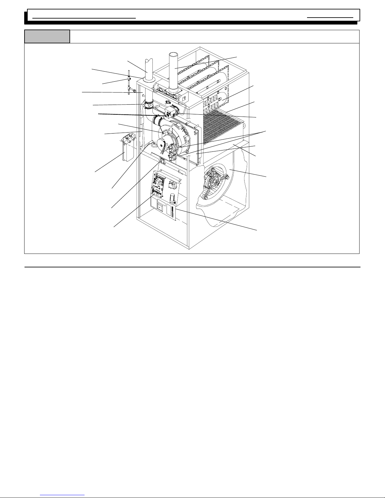
Figure 1
Furnace Vent Pipe
(Vent Pipe Connection through
Side Panel on Some Models)
Vent Pipe Grommet
Manual Gas Valve
Rating Plate
Vent Drain Fitting
Diagnostic Light
Combustion Air Blower
Condensate Trap
3
/4²²²² OD Transition Box
Drain Hose
Component Locations for Four Position Furnaces
5
/8²²²² OD Vent Pipe
Drain Hose
Door Interlock Switch
Air Intake Pipe
(Dual Certified or Direct
Vent furnaces)
Primary Heat Exchanger
Secondary Heat Exchanger
Gas Valve/Ignition Module
Pressure Switches
Plastic Transition Box
Coils Air Baffle
Circulating Air Blower
Fan/Delay Control
3. FURNACE THEORY OF OPERATION
The high efficiencies and lower profile (compared to previous
series) of this furnace have been obtained using design techniques not typical of traditional furnace designs. A brief description of these new design techniques and the purpose
they serve follows.
1. Reducing the height of the furnace while maintaining
the high efficiency of pervious models required working the heat exchanger more efficiencly and yet minimizing the overall size.
The design required to achieve these results is the “SERPENTINE” design, wherein the flue gasses must follow a
serpent shaped passage through the heat exchanger via
convection.
This “Serpentine” path is resistive to normal convective flow,
and requires that a partial vacuum be created at the outlet
of the heat exchanger to maintain the flow of flue products
through the heat exchanger.
2. The serpentine heat exchanger design does not lend
itself well to the ribbon type, or slotted port type burner
found in more traditional design furnaces for the following reasons:
A.The s econdary combustion airflows at right angles to the
burner flame, making it likely to “pull” the flame off a ribbon
or slotted port type burner.
D C Motor Control
(some models)
dwg 25-- 23--29a
B.The flame “height” of a ribbon or slotted port type burner
would make it difficult (if not impossible) to prevent impingement of the flame on the heat exchanger surfaces
whole maintaining the low profile heat exchanger.
For these reasons, an “INSHOT” type burner is used in this
series. The inshot burner (also called a “jet” burner) fires a
flame straight out its end. This burner is designed to fire into
a tube style heat exchanger, making it an ideal application in
the tube--like passages of the serpentine heat exchanger.
3. In order to extract the maximum amount of heat possible from the flue gasses, a secondary heat exchanger (condenser) is connected to the outlet of the primary
heat exchanger. This condenser removes additional
heat from the flue gasses, causing their temperature to
drop below dew point, thus increasing operating efficiency of the furnace, and the term “Condensing Fur-
nace”. This results in the forming of condensation (water) which then must be routed to a drain.
4. The placement of the secondary heat exchanger at the
outlet of the primary heat exchanger creates additional
resistance to the flow of gasses.
5. To overcome the resistance to convective flow of the
Primary and Secondary heat exchangers requires the
use of an Induced Draft Combustion Blower Assembly.
440 08 2002 02
3
Page 6
Service
Manual
Two- Stage Multi Position Furnace
6. The Combustion Blower Assembly is mounted on the
outlet side of the Secondary heat exchanger, This
blower creates a partial vacuum (negative pressure)
within the heat exchangers drawing the flue products
out of the furnace.
4. ELECTRICAL SUPPLY
!
Electrical shock hazard.
Turn OFF electric power at fuse box or service panel
before making any electrical connections and ensure a proper ground connection is made before
connecting line voltage.
Failure to do so can result in death, personal injury
and/or property damage.
SUPPLY CIRCUIT
The furnace cannot be expected to operate correctly unless
it is properly connected (wired) to an adequately sized (15
amp.) single branch circuit.
7. The Combustion Blower Assembly is mounted on the
outlet side of the Secondary heat exchanger, This
blower creates a partial vacuum (negative pressure)
within the heat exchangers drawing the flue products
out of the furnace.
5. An alternate check would be to check for continuity
from the Neutral to a cold water pipe, (Pipe must be
metal, and must have a continuous, uninterrupted connection to ground) or to a continuous, uninterrupted
connection to ground) or to a driven ground rod.
6. Any readings other than zero Ohms would indicate a
poor ground, or no ground.
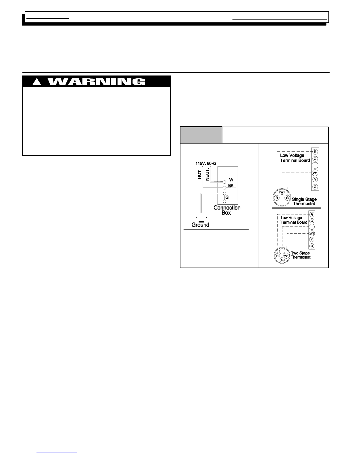
Figure 2
Electrical Connections
W2
SUPPLY VOLTAGE
Supply voltage to the furnace should be a nominal 115 volts.
It MUST be between 97 volts and 132 volts. Supply voltage
to the furnace should be checked WITH THE FURNACE IN
OPERATION. Voltage readings outside the specified range
can be expected to cause operating problems. Their cause
MUST be investigated and corrected.
ELECTRICAL GROUND
Grounding of the electrical supply to ALL FURNACES IS
REQUIRED for safety reasons.
POLARITY
CORRECT POLARITY of the line voltage supply to all furnaces is also REQUIRED for safety reasons.
CHECKING GROUNDING AND POLARITY
Grounding may be verified as follows:
1. Turn the power supply “OFF”.
2. Using an Ohmmeter check for continuity between the
Neutral (white) wire and Ground wire (green) of the
supply circuit.
3. With the Ohmmeter set on the R x 1 scale, the reading
should be zero Ohms.
4. A zero Ohm reading indicates that the neutral is
grounded back to the main panel.
W2
W2
Polarity may be verified as follows:
1. Turn the power supply “ON”.
2. Using a Voltmeter check for voltage between the Hot
(Black) and Neutral (White) wire of supply circuit.
3. Reading should be Line (Supply) Voltage.
4. Check for Voltage between the Neutral (White) wire
and Ground wire of the supply circuit.
5. Reading should be zero Volts. (if line voltage is read,
polarity is reversed)
6. A zero Volt reading indicates there is no voltage potential on Neutral wire.
7. Double check by checking for voltage between the Hot
(Black) wire and Ground wire of the supply circuit.
8. Reading should be Line (supply) Vo ltage.(ifzero
volts is read, there is no ground, or polarity is reversed.)
440 08 2002 02
4
Page 7
Two- Stage Multi Position Furnace
T
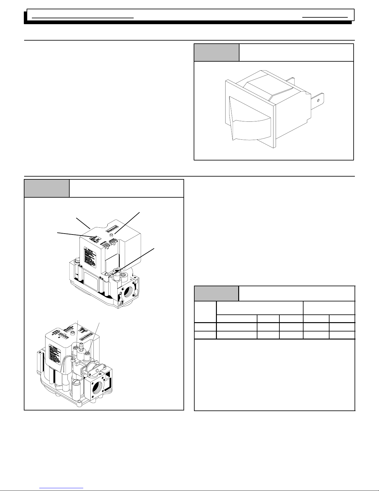
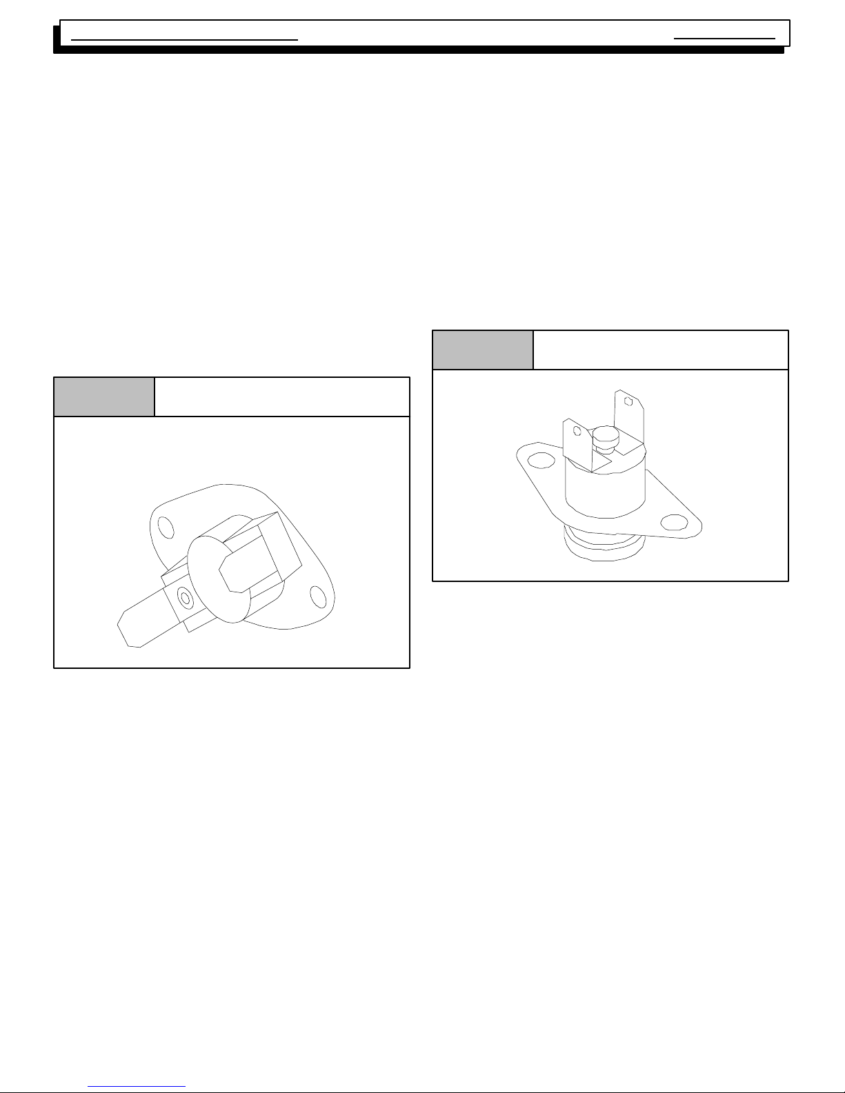
5. INTERLOCK SWITCH
The blower compartment door of all models is equipped with
an interlock switch. This switch is “Normally Open” (closes
when the door is on the furnace) and interrupts furnace operation when the door is open. This interlock switch is a safety device, and SHOULD NEVER BE BY--PASSED.
Since this is a single pole switch, (breaking only one side of
the line) proper line voltage is essential to insure that furnace
components are not “HOT” when switch is open. (See
Checking Grounding and Polarity)
6. GAS SUPPLY
Figure 3
Service
Typical Interlock Switch
Manual
10--12--96
On/Off
Switch
Manifold Pressure
Adjustment
OUTLET
INLET
Typical Gas Valve HoneywellFigure 4
Manifold
Adjustment
(Hidden)
LO
HI
INLET
25--22--49a
Diagnostic Light
(on some models)
Pilot
Adjustment
OUTLET
25--22--25a
NATURAL GAS
Inlet (Supply) pressure to the furnace should be checked (at
the gas valve) with ALL OTHER GAS FIRED APPLIANCES
OPERATING. Inlet (Supply) pressure to the furnace under
these conditions MUST be a minimum of 4.5² W.C. (Water
Column). If the inlet pressure is less, it may be an indication
of undersized piping or regulator problems.
L.P. GAS
Inlet (Supply) pressure to the furnace should be checked in
the same manner as for Natural Gas, however with L.P. Gas,
the inlet pressure MUST be a minimum of 11² W.C. If this
cannot be obtained, problems are indicated in either the regulator or pipe sizing.
Tab l e 1 Gas Pressures Below 2000¢¢¢¢
Gas
ype
Recommended Max. Min. Hi Fire Lo Fire
Natural 7² 14² 4.5² 3.5² 1.7²
LP 11² 14² 11² 10² 4.9²
· With Propane gas, the rated input is obtained when the
BTU content is 2,500 BTU per cubic foot and manifold
pressure set at 10²²²² W.C .
· If Propane gas has a different BTU content, orifices
MUST be changed by licensed Propane installer.
· Measured input can NOT exceed rated input.
· Any major change in gas flow requires changing burner
orifice size.
Supply Pressure
Important Note:
Manifold
Pressure
An adequately sized gas supply to the furnace is required for
proper operation. Gas piping which is undersized will not provide sufficient capacity for proper operation. Piping should
be sized in accordance with accepted industry standards.
CHECKING INPUT (FIRING) RATE
Once it has been determined that the gas supply is correct
to the furnace, it is necessary to check the input (firing) rate,
This can be done in two (2) ways. First by checking and adjusting (as necessary) the manifold (Outlet) pressure. The
second way is to “Clock” the gas meter.
440 08 2002 02
5
Page 8
Service
Btu/C
u.F
t
Manual
Two- Stage Multi Position Furnace
!
Fire or explosion hazard.
Turn OFF gas at shut off before connecting
manometer.
Failure to turn OFF gas at shut off before
connecting manometer can result in death,
personal injury and/or property damage.
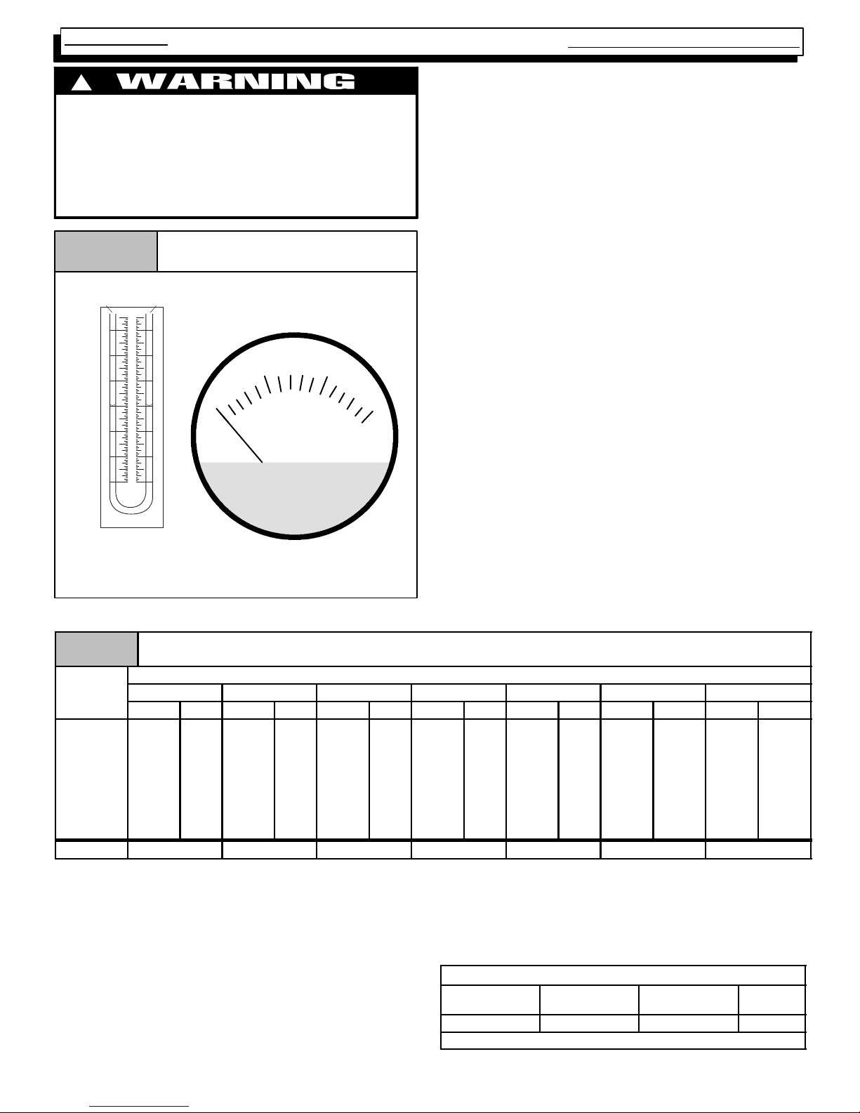
Gas Pressure Testing DevicesFigure 5
Pressure Connections
3
2
1
0
1
2
3
0
INCHES OF WATER
510
15
MAGNEHELIC
MAX. PRESSURE 15 PSIG
CHECKING MANIFOLD PRESSURE
1. Connect manometer or Magnehelic gauge to the
tapped opening on the outlet side of gas valve. Use a
manometer witha0to12² minimum water column
range.
2. Turn gas ON. Operate the furnace on high fire by using
a jumper wire on the R to W1 & W2 thermostat connections on the fan board.
3. Remove the adjustment cover on the gas valve. Turn
adjusting screw counterclockwise to decrease the
manifold pressure and clockwise to increase. See
Figure 4.
4. Set the manifold pressure to value shown in Table 1 or
Tab l e 2.
5. Operate the furnace on low fire by using a jumper wire
on the R to W1 thermostat connections on the fan
board.
Note: The fourth (4th) DIP switch should be in the on
position to set the low fire manifold pressure. (See wiring digram)
6. Repeat steps 4 and 5 for low fire operation.
7. When the manifold pressures are properly set, replace
the adjustment screw covers on the gas valve.
8. Remove the jumper wires from the thermostat connec-
Typical "U" Tube
Manometer
tions on the fan board. Remove manometer and replace plug in gas valve.
9. Reture fourth (4th) DIP switch to previous setting.
10. Replace the burner compartment door.
MANIFOLD PRESSURE AND ORIFICE SIZE FOR HIGH ALTITUDE APPLICATIONS
Tab l e 2
HeatValue
.
800 3.5 1.7 3.5 1.7 3.5 1.7 3.5 1.7 3.5 1.7 3.5 1.7 3.5 1.7
850 3.5 1.7 3.5 1.7 3.5 1.7 3.5 1.7 3.5 1.7 3.5 1.7 3.5 1.7
900 3.5 1.7 3.5 1.7 3.5 1.7 3.5 1.7 3.5 1.7 3.5 1.7 3.4 1.7
950 3.5 1.7 3.5 1.7 3.5 1.7 3.5 1.7 3.3 1.6 3.2 1.6 3.1 1.5
1000 3.5 1.7 3.4 1.7 3.3 1.6 3.2 1.5 3.0 1.5 2.9 1.4 2.8 1.4
1050 3.2 1.6 3.1 1.5 3.0 1.5 2.9 1.4 2.7 1.3 2.6 1.3 2.5 1.2
1100 2.9 1.4 2.8 1.4 2.7 1.3 2.6 1.3 2.5 1.2 2.4 1.2 2.3 1.1
Orifice Size #42 #42 #42 #42 #42 #42 #42
0-- 1999 2000-- 2999 3000--3999 4000-- 4999 5000-- 5999 6000-- 6999 7000-- 7999
High Low High Low High Low High Low High Low High Low High Low
“CLOCKING” GAS METER (NATURAL GAS)
1. Check with gas supplier to obtain ACTUAL BTU content of gas.
2. Turn “OFF” gas supply to ALL other gas appliances.
High Altitude Pressure Chart
2000--8000 ft. (Natural Gas)
Elevation Above Sea Level
5. Operate furnace on LOW fire, and time how many seconds it takes the smallest (normally 1 cfh) dial on the
gas meter to make one complete revolution.
6. Calculate LOW fire input rate by using ACTUAL BTU
content of gas in formula shown in example.
3. Operate furnace on HIGH fire, and time how many seconds it takes the smallest (normally 1 cfh) dial on the
gas meter to make one complete revolution.
4. Calculate HIGH fire input rate by using ACTUAL BTU
content of gas in formula shown in example.
440 08 2002 02
6
Example
Natural Gas
BTU Content
1,000 3,600 48 75,000
No. of Seconds
Per Hour
1,000 x 3,600 ¸ 48 = 75,000 BTUH
Time Per Cubic
Foot in Seconds
BTU Per
Hour
Page 9
Two- Stage Multi Position Furnace
7. L.P. PRESSURE SWITCH
Models converted to operate on L.P. Gas will be installed
with an L.P. Pressure Switch. The switch will be located in the
gas supply line (in a “Tee”fitting), just ahead of the gas valve.
The purpose of this switch is to prevent furnace operating under low line (Supply) pressure conditions. Operating under
low line pressure conditions, can create problems such as incomplete combustion, flashback, sooting, etc.
The switch is a “Normally Open” pressure operated switch
that is wired in series with the furnace (Lo--fire) pressure
switch. The L.P. Pressure Switch closes when line (Supply)
pressure is 8.0² W.C. or higher. the L.P. Pressure Switch
Opens if line pressure falls below 6.0²+0.6² W.C. interrupting power to the gas valve.
It is located (electrically) between the Main Limit Switch and
the furnace (vent) pressure switch. The switcht is located
(electrically) between the Furnace (Lo--fire) pressure switch
and the gas Valve.
8. HIGH ALTITUDE OPERATION
These furnaces are designed to operate in the majority of the
country without modifications. At altitudes over 2,000¢ above
sea level, however, certain measures need to be taken to insure continued, safe reliable operation. For example, units
must be de--rated for altitude (by adjusting manifold pressure and/or changing orifice size) based upon the type of fuel
(I.E. Natural Gas or L.P. gas), Btu content of the gas, and
installed altitude.
Service
Figure 6
ALL UNITS must have a high altitude pressure switch
installed at altitudes above 4,000¢ above sea level.
When servicing a unit installed at altitudes above 2,000¢ insure that it has been properly modified to operate at that altitude. See the sections on Gas pressure, and pressure
switches to obtain specific information for you particular
installation altitude.
Typical L.P . Pressure Switch
Manual
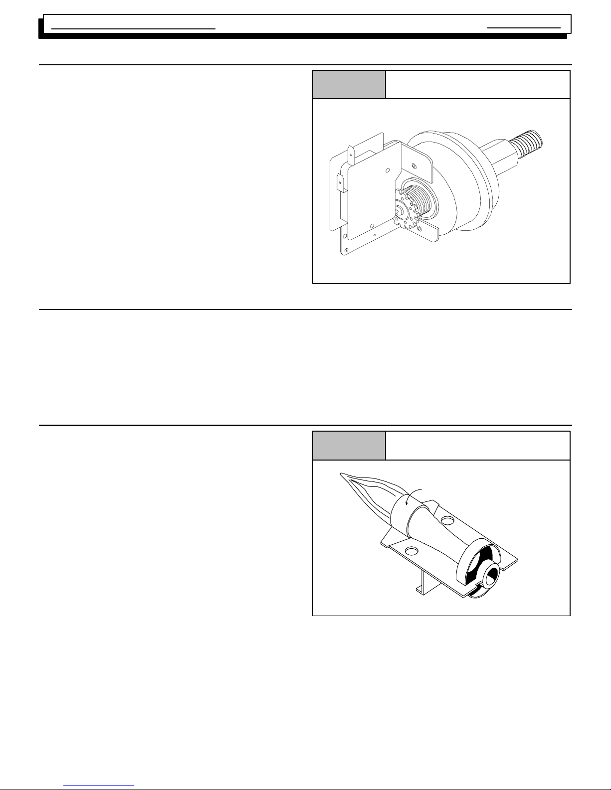
9. BURNERS
Burners used in this series of furnace are of the “INSHOT”
type. Their operation can be compared to that of a torch in
that they produce a hard, sharp, somewhat noisy flame.
Noise should not be an issue, however, because of the
closed burner box design. In order to insure that the burners
are operating properly , and at their design noise level, proper
adjustment of the gas (manifold) pressure is essential. For
further information on manifold pressure adjustments check
the section on “Gas Supply”.
The burners used in this series ARE NOT EQUIPPED WITH
AIR SHUTTERS, as none are required. Proper operation
(flame characteristics) is obtained by insuring that the orifice
size, and manifold pressure are correct for the fuel being
used and the altitude of the installation.
Figure 7
Main Burner
Burner Face
10-- 10--78
440 08 2002 02
7
Page 10

Service
50Mbt
75Mbtu,100Mb
tu&125Mbt
50Mbt
75Mbtu,100Mb
tu&125Mbt
Manual
10. CHECKING TEMPERATURE RISE
Two- Stage Multi Position Furnace
Figure 8
Thermometer:
Return Air Temp.
Return
Air Flow
The furnace is designed to operate within a certain specified
range of temperature rise.
Operating the furnace outside the specified range may result
in lower efficiency and/or comfort levels, as well as premature combustion component failures.
Simply stated, the temperature rise through the furnace is
the difference in temperature between the return air, and the
supply air.
NOTE: BEFORE CHECKING TEMPERATURE RISE BE
CERTAIN THAT MANIFOLD PRESSURE IS PROPERLY
ADJUSTED.
Checking Temperature Rise
Supply
Air Flow
Thermometer;
Supply Air Temp.
2- STAGE MODELS
Model Fire Range
u
Always check current “Technical Support Manual”
HI 35°F--65°F
LOW 25°F--55°F
HI 40°F--70°F
u
LOW 30°F--60°F
ALLOWABLE TEMPERATURE RISE FOR
VARIABLE SPEED MODELS
Model Fire Range
u
Always check current “Technical Support Manual”
Operate the furnace for 15 minutes before taking temperature readings. Subtract the return air temperature from the
supply air temperature. The result is the temperature rise.
Compare with the allowable rise listed for the model (size)
you are checking.
Temperature Rise can be checked by placing a thermometer
in the return air duct within 6¢ of furnace. Place a second thermometer in the supply duct at lease two (2) ft. away from the
furnace. (This will prevent any false readings caused by radiation from the furnace heat exchanger) Make sure that the
FILTER IS CLEAN and that ALL REGISTERS AND/OR
DAMPERS ARE OPEN.
If the rise is not within the specified range, it will be necessary
to change the heating blower speed. If the rise is too high,
it will be necessary to increase the blower speed. If the
rise is too low, it will be necessary to reduce the blower
speed.
Example:
Supply T emp. 170
Return Temp. 70°
Temperature Rise 100° = Too High
HI 35°F--65°F
LOW 35°F--65°F
HI 40°F--70°F
u
LOW 40°F--70°F
°
ALLOWABLE TEMPERATURE RISE FOR
11. ROOM THERMOSTATS
Room thermostats are available from several different
manufactures in a wide variety of styles. They range from the
very simple and inexpensive Bi--metallic type to the complex.
They are simply a switch (or series of switches) designed to
turn equipment (or components) “ON” or “OFF” at the desired conditions.
440 08 2002 02
Solution: Increase Blower Speed
An improperly operating, or poorly located room thermostat
can be the source of perceived equipment problems. A careful check of the thermostat and wiring must be made then to
insure that it is not the source of problems.
8
Page 11
Two- Stage Multi Position Furnace
Service
Manual
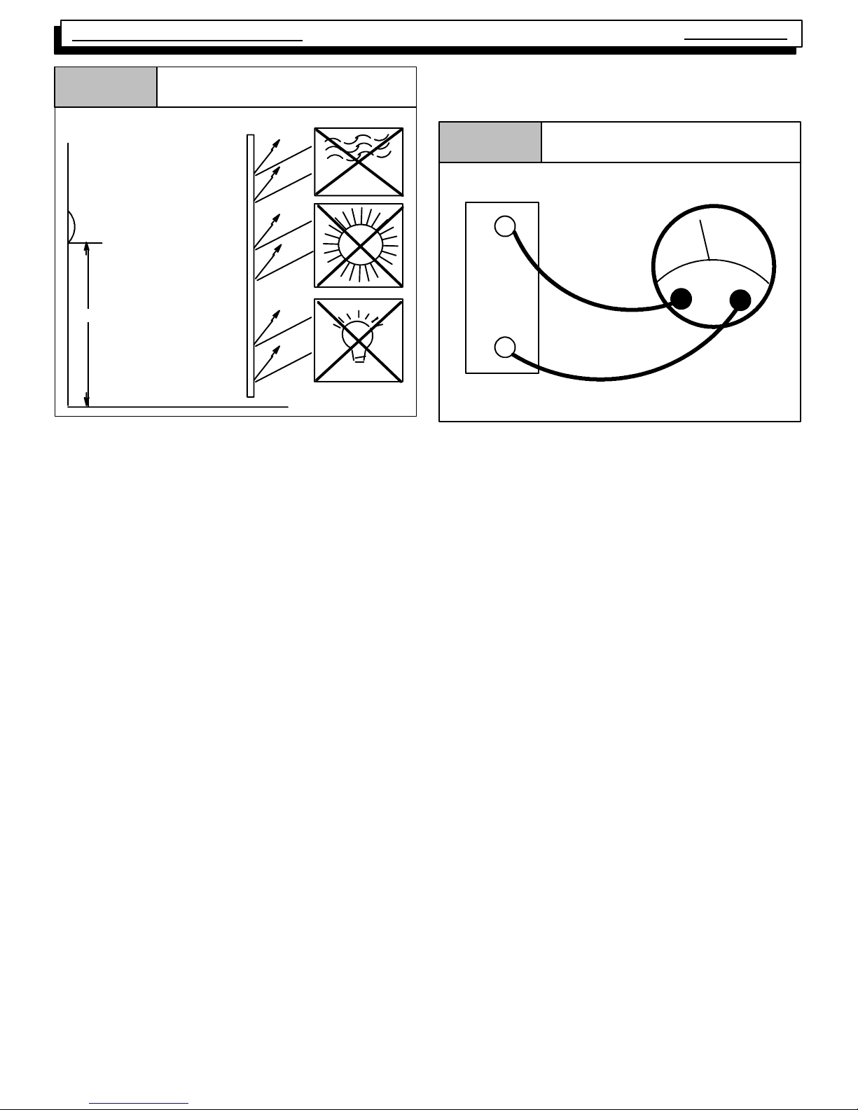
Figure 9
Thermostat Location
DRAFTS
THERMOSTAT
SUN
SHIELD
5 ft.
LIGHT
LOCATION
The thermostat should not be mounted where it may be affected by drafts, discharge air from registers (hot or cold), or
heat radiated from the sun of appliances. Never install in alcoves, bathrooms or bedrooms.
The thermostat should be located about 5 ft. above the floor
in an area of average temperature, with good air circulation.
Normally, an area in close proximity to the return air grille is
the best choice.
Mercury bulb type thermostats MUST be level to control temperature accurately to the desired set--point. Electronic digital type thermostats SHOULD be level for aesthetics.
HEAT ANTICIPATORS
Heat anticipators are small resistance heaters built into most
electric--mechanical thermostats. Their purpose is to prevent wide swings in room temperature during furnace operation.
In order to accomplish this, the heat output from the anticipator must be the same regardless of the current flowing
through it. Consequently , most thermostats have an adjustment to compensate for varying current draw in the thermostat circuit.
The proper setting of heat anticipators then is important to
insure proper temperature control and customer satisfaction.
The best method to obtain the required setting for the heat
anticipator, is to measure the actual current draw in the con-
trol circuit (“W”) using a low range (0--2.0 Amps) Ammeter.
(See Figure 10) After measuring the current draw, simply
set the heat anticipator to match that value.
Figure 10
Measuring Current Draw
W
Amps
R
Subbase
Ammeter
If a low range ammeter is not available, a “Clamp--on” type
meter may be used as follows:
1. Wrap EXACTLY ten (10) turns of wire around the jaws
of a clamp--on type ammeter.
2. Connect one end of the wire to the “W” terminal of the
thermostat sub--base, and the other to the “R” terminal.
3. Turn power on, and wait approximately 1 minute, then
read meter.
4. Divide meter reading by 10 to obtain correct anticipator
setting.
NOTE: For 2 Stage heating thermostats the above proce-
dure MUST be perform ed twic e. Once for first
stage (W
1), and once f or s econd st age (W2), if
both stages have adjustable heat anticipators.
If an ammeter is not available, a setting of 0.10 amps may
be used for models equipped with the HONEYWELL
SV9541Q Gas Valve/Ignition Control. They should, however, provide satisfactory operation in most cases.
Electronic thermostats do not use a resistance type anticipator. These thermostats use a microprocessor (computer)
that determines a cycle rate based on a program loaded into
it at the factory.
These cycle rates are normally field adjustable for different
types to equipment. The method of adjustment, however,
varies from one thermostat manufacturer to another. Check
with the thermostat manufacturer to find out the proper way
of adjusting the cycle rate.
440 08 2002 02
9
Page 12
Service
Manual
12. CONTROL WIRING
Control wiring is an important part of the total equipment
installation, since it provides the vital communications link
between the thermostat, and the equipment. It is often
overlooked as the source of equipment malfunctions. Control wiring that is either too long, undersized, or improperly
connected (be it simply loos e, or on the wrong terminal)
can in fact be the source of many equipment problems.
Two- Stage Multi Position Furnace
operation, the furnace will shift from low fire to high fire as
requested by the thermostat. The thermostat heat anticipators should be adjusted to a .10 setting for both types of thermostats.
Low voltage connections to furnace must be made on terminal board to fan control.
ALWA YS check to make sure that the control wiring is connected to the proper terminal(s) of the equipment and thermostat you are using. Remem ber, also, that therm ost at
terminals are not always identified alike by different thermostat manufacturers. Connections MUST be clean and
tight to insure trouble--free operation.
The controls of this series of 2--Stage furnaces ar e designed to provide 2--Stage operation using a Two (2) Stage
Thermostat, ONLY as follows:
The 2--stage furnace control will operate with either a single
stage or a two stage heating thermostat and will provide
2--stage heating operation. For single stage thermostat
installations, the R and W wires from the thermostat connect
to the R and W1 connections on the furnace control. Note:
The fourth (4th) DIP switch must be in the off position, failure
to change DIP switch will result in Lo Fire ONLY operation.
(See furnace wiring digram) See “Furnace Wiring Diagram”
for switch settings. Failure to set DIP switch will result in Lo
fire operation ONLY with single stage thermostat. During operation, the furnace will operate on low fire for 12 minutesIf
the heat request exists for more than 12 minutes. If the heat
request exists for more that 12 minutes, the furnace will automatically shift to the high fire mode for the remaining duration
of the heating cycle. For two stage thermostat installations,
the R, W1 and W2 wires from the thermostat connect to the
R, W1 and W2 connections on the furnace control. During
The ELECTRO NI C CONTROLS used on t his series RESPOND DIFFERENTL Y to certain control wiring practices
which have been generally accepted in the HVAC industry
for many years.
For Example: For years, installers have run a wire from the
“Y” t er m inal of the room thermost at and connec t ed it directly to the contactor coil of a condensing unit. (not making any connection to the furnace with this wire) Then, run
the low voltage “Common” wire from the condensing unit
back to the “C” terminal of the furnace.
With the HONEYWELL ST9162A electronic Fan Timer/
Furnace Control used in the models of this series, however, the “Y” terminal of the furnace does in fact serve a particular purpose. Failure to connect it will result in certain
improper operation as follows:
The COOLING fan speed is energized via the “Y” terminal.
Failure to connect the thermostat “Y” terminal to the “Y”
terminal on the control will result in the failure to energize
the COOLING speed on a call for cooling from the thermostat. (Depending upon the model, either the LOW HEATING speed or the CIRCULATING speed will be energized
instead via the “G” terminal)
For more detailed information about this control, see the
section on the ST9162A control beginning on page 23 of
this manual.
13. LIMIT SWITCHES
Two (2) different kinds of limit switches are used on this series of furnaces. They are the main limit and roll out limit
switches. The main limit, and roll out limit switches are used
on all models.
NOTE: All limit switches are safety devices and other
than for testing purposes, should never be jumped out!
Limit switches are “normally closed” electrical switches, designed to open when their predetermined “limit setting” has
been reached.
It should also be remembered, that when a limit switch
opens, it more than likely is not due to a bad switch! The
cause of the opening limit must be found and corrected, be-
440 08 2002 02
fore the furnace can resume proper operation.
!
Fire hazard.
Limit controls are factory preset and MUST NOT be
adjusted. Use ONLY manufacturer’s authorized
replacement parts.
Failure to do so can result in death, personal injury
and/or property damage.
The specific functions of the two (2) limit switches used in
this series of furnaces are as follows:
10
Page 13
Two- Stage Multi Position Furnace
Service
Manual
MAIN LIMIT SWITCH
A “Normally Closed” switch located on the front partition of
the furnace. It monitors supply air temperature, and interrupts furnace (burner) operation when a supply air temperature is sensed which would result in the furnace exceeding
Maximum allowable outlet air temperature. While the main
limit is open, combustion blower, and/or the circulating blower will be energized continuously. This control is an “Automatic” reset control, which will reset itself when the temperature sensed drops to a safe level.
If furnace (burner) cycles on this limit switch, (I.E. switch
opens and closes during furnace operation) it is more than
likely due to a high temperature rise through the furnace.
(See checking temperature on page 8 of this manual)
High temperature rise can be caused by either OVER
FIRING (high manifold pressure. incorrect orifices, etc.) or
LOW AIR FLOW (dirty filter, blower speed too low, excessive
static in duct system, etc.)
Figure 11
Typical Limit Switch
If, however , the switch is found to be opening prematurely,
then it should be replaced. When replacing ANY limit switch,
use ONLY a switch of EXACTLY the same temperature setting. Use of a different temperature limit switch can create a
dangerous situation. Some of the main limit switches used
in this series are SIMILAR IN APPEARANCE. DIFFERENT
TEMPERATURE SETTINGS, HOWEVER, ARE USED for
different models. Be certain you have the correct control for
the model you are servicing.
ROLL OUT LIMITS
Those “Normally Closed” unit switches (wired in series with
the Main Limit switch) on the top are mounted on the bottom
(left & right) of the burner box.
The switches are manual reset type. When replacing this
switch, be absolutely certain the correct one is used.
Figure 12
Typical Roll Out Limit Switch
To verify this, the cut--out (opening) point of the switch should
be checked (using a thermocouple type thermometer connected to the face of the switch) as follows:
1. Operate furnace for several minutes.
2. Block return air grille(s) to furnace.
3. Observe temperature at which switch opens (burner
operation ceases).
4. Remove blockage from return grille(s).
5. Observe temperature at which switch closes (burner
operation resumes).
6. Compare readings with the limit setting listed in the
appropriate chart for the model you are servicing.
If switch is opening within the specified range, then it is simply doing its job, and the cause of the over--temperature must
be determined and corrected.
CAUTION
NEVER use an automatic reset roll out switch to replace
a manual reset type roll out switch.
Doing so may cause potentially unsafe and/or intermittent operation.
The roll out switch monitors the temperature inside the burner box, and interrupts furnace (burner) operation when its
temperature indicates flame roll out has occurred.
If the roll out switch has opened, the cause must be determined. Some possible reasons for flame roll out include a restricted primary or secondary heat exchanger or over fired
furnace.
MANUAL RESET SWITCH MODELS
Furnace models which are equipped with a Honeywell
ST9162A Fan timer/furnace control use a manual reset roll
out switch. Once the roll out switch has opened, burner operation will be prevented until the roll out switch is “Manually
Reset” by pressing the red button located on the switch.
While the roll out switch is open, (Depending upon the particular model) the combustion blower and/or circulating blower
will be energized continuously.
440 08 2002 02
11
Page 14
Service
Manual
14. PRESSURE SWITCHES
Two- Stage Multi Position Furnace
TRANSITION PRESSURE SWITCH
Under normal operating conditions, sufficient pressure is developed by the exhaust (combustion) blower to close the
switch, and permit the burner to operate. As the condensate
drain begins to back--up, however, the pressure begins to reduce. When the pressure drops sufficiently, burner operation
will be prevented until the condition is corrected.
STANDARD PRESSURE SWITCHES - ALL
MODELS
Model
Condensing
50, 75 &100
125
Always check current “Technical Support Manual”for
Part Nos.
Max.
Close
--1.70² W.C.
--2.00² W.C.
Open Part #
--1.50 + 0.10² W. C .
--
--1.80 + 0.10² W.C .
--
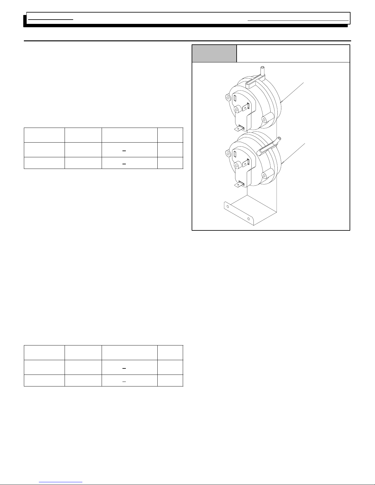
BLOWER PRESSURE SWITCH
An air proving switch (pressure switch) is used on all models
to insure that a draft has been established through the heat
exchanger before allowing burner operation.
To insure continued SAFE, RELIABLE, operation, NEVER
SUBSTITUTE a pressure switch with one that is similar in
appearance. ONLY FACTORY PROVIDED or
AUTHORIZED SUBSTITUTES ARE ACCEPTABLE.
All models installed at altitudes of 4,000¢ above sea level or
higher require replacing the standard pressure switch with a
high altitude pressure switch. The different pressure switch
settings allow continued SAFE, RELIABLE, high altitude
operation.
Note: Transition switch checks lo--fire airflows & blocked
condensate. Blower switch checks Hi--fire airflow.
HIGH ALTITUDE PRESSURE SWITCHES - ALL
MODELS
Model
Condensing
50, 75 &100
125
Always check current “Technical Support Manual”for
Part Nos.
Under normal operating conditions, sufficient negative pressure will be created to close the pressure switch, and keep
it closed to keep furnace operating. Under abnormal conditions, however, such as a restricted vent pipe, or a leak in one
of the heat exchangers, sufficient negative pressure will not
be created. This will result in the switch failing to close or failing to remain closed during furnace operation.
440 08 2002 02
Max.
Close
--1.40² W.C.
--1.70² W.C.
Open Part #
--1.20 + 0.10² W.C .
--
--1.50 + 0.10² W.C .
--
1013165
1013157
Figure 13
Pressure Switches
Blower
(Hi--fi re)
Transition
(Lo--fire)
25--23--72
When servicing a unit whose pressure switch will not close,
or remain closed during operation, the operating pressure of
that furnace should be checked and compared to
approximate operating pressures listed in Tab l e 3 and the
switch setting(s) listed above for the model family you are
servicing.
It is important to remember, that greater negative pressures
are created by the furnace when “Hot” (I.E. upon initial start-up) than when “Cold” (I.E. after furnaces has been in operation for a few minutes). Because of this, furnace pressure
should ONLY be checked when “HOT” to insure accurate
readings.
Tab l e 3 lists approximate operating pressures for Direct
Vent (I.E. Two Pipe) installations of models in this series.
They were obtained in a test lab, under controlled conditions
using two (2) specific vent lengths. They are included in this
manual to provide you with a “Barometer” to gauge our pressures against. The pressures you obtain in the field will differ
slightly from these figures based upon vent length, gas pressure, operating temperature, etc.
Major discrepancies in pressures, will normally cause
problems with pressure switch operation. These Major discrepancies should be investigated as follows:
12
Page 15
Two- Stage Multi Position Furnace
50Mbtu&
100Mb
t
Table 3 APPROXIMATE OPERATING PRESSURES (INCHES OF W.C.)
@Blower/@Transition
Model Vent Length (High Fire) (Low Fire)
50 Mbtu &
75 Mbtu
u
125 Mbtu
Always check current “Technical Support Manual”for
updated information.
Short -- (5 Ft. No Elbows) --1.80/--2.60 --1.20/--1.90
Long -- (40 Ft. + 5 90° Elbows) --1.30/--2.30 --1.00/--1.80
Short -- (5 Ft. No Elbows) --1.80/--2.60 --1.20/--1.90
Long -- (40 Ft. + 5 90° Elbows) --1.70/--2.50 --1.00/--1.80
Short -- (5 Ft. No Elbows) --1.80/--2.60 --1.30/--2.30
Long -- (40 Ft. + 5 90° Elbows) --1.70/2.50 --1.20/--2.20
2. Leak (lack of restriction) on the Inlet side of the combustion blower.
Service
Manual
Lower (Lesser) Negative Pressures
Lower than normal negative pressures measured at the
Combustion Blower may be caused by:
1. Restriction on the Outlet side of the combustion blower. (I.E. Blocked Flue, Vent too long, Heat Exchanger
leak, etc.)
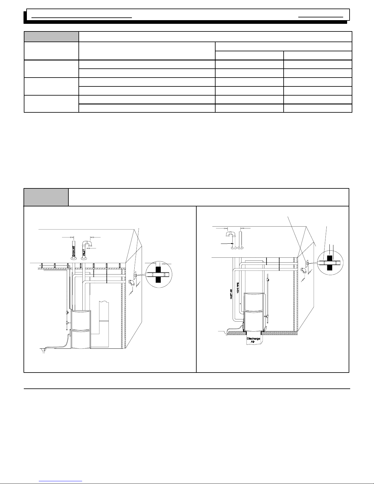
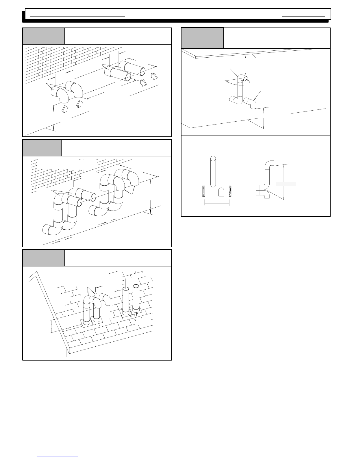
Figure 14
UPFLOW
*8² Min.
20¢ Max.
in same
atmospheric zone
Vent Pipes MUST be
supported Horizontally
and Vertically
Typical Vent/Combustion Air Piping Installation
Aluminum or non-- rusting shield recommended.
(See Vent Termination Shielding for dimensions).
Inlet Pipe
DISCHARGE AIR
Coupling on ends of exhaust
pipe. Total pipe & coupling
outside structure = 8²
*8² Min.
20¢ Max.
in same atmospheric zone
Higher (Greater) Negative Pressures
Higher than normal negative pressures measured at the
Combustion Blower may be caused by:
1. Restriction on the Inlet side of the combustion blower.
(I.E. Plugged Heat Exchanger, air inlet orifice too
small)
DOWNFLOW
Inlet Pipe
Vent Pipes MUST
be supported
Horizontally and
Vertically
See Vent Termination Shielding
in Vent Section.
*8² Min.
20¢ Max.
in same
atmospheric
zone
Coupling on inside and
outside of wall to
restrain vent pipe
8² Min.
*8² Min.
20¢ Max.
in same
atmospheric zone
* Increase minimum from 8² to 18² for cold climates (sustained temperatures below 0 ° F).
15. VENT/COMBUSTION AIR PIPING
Vent and combustion air piping are an extremely important
part of the total furnace installation. Improperly installed or
inadequately sized vent and/or combustion air piping can be
the source of many perceived furnace problems.
For example, most problems associated with pressure
switch operation can normally be traced to short comings in
the vent and/or combustion air piping. Anytime these type
25--23--33
* Increase minimum from 8² to 18² for cold climates (sustained temperatures
below 0°F).
25--23--33a
problems arise, a thorough inspection of the vent and/or
combustion air piping should be conducted.
ALL MODELS require a vent (exhaust) pipe to carry flue
products to the outside of the structure.
Direct VENT (ONLY) models require a combustion air inlet
to bring in all air for combustion from outside the structure.
440 08 2002 02
13
Page 16

Service
Manual
Two- Stage Multi Position Furnace
DUAL CERTIFIED models require a combustion air inlet
pipe to bring in all air for combustion from outside the structure only when installed as a Direct Vent Furnace (I.E. Two
Pipe Installation)
16. STANDARD VENT TERMINATION
Vent/Combustion Air Piping Charts
Single Piping Chart
Tab l e 4
50,000 & 75,000 Btuh Furnaces
40¢ & (5) 90° elbows with 2² PVC pipe
100,000 & 125,000 Btuh Furnace
40¢ & (5) 90° elbows with 3² PVC pipe
Elbows are DWV Long Radius Type for 2² and 3² vents.
If more than five elbows are required, reduce the length of both
the inlet and exhaust pipes 5¢ for each additional elbow used.
NOTE: It is allowable to use larger diameter pipe and fitting than
shown in the tables but not smaller diameters than shown.
Dual Piping Chart
Tab l e 5
50,000 & 75,000 Btuh Furnaces
40¢ & (5) 90° elbows with 2² PVC pipe
100,000 & 125,000 Btuh Furnace
40¢ & (5) 90° elbows with 3² PVC pipe
Elbows are DWV Long Radius Type for 2² and 3² vents.
If more than five elbows are required, reduce the length of both
the inlet and exhaust pipes 5¢ (1.5m) for each additional elbow
used.
* Feet of pipe is whichever pipe run is the longest, either inlet or
outlet side.
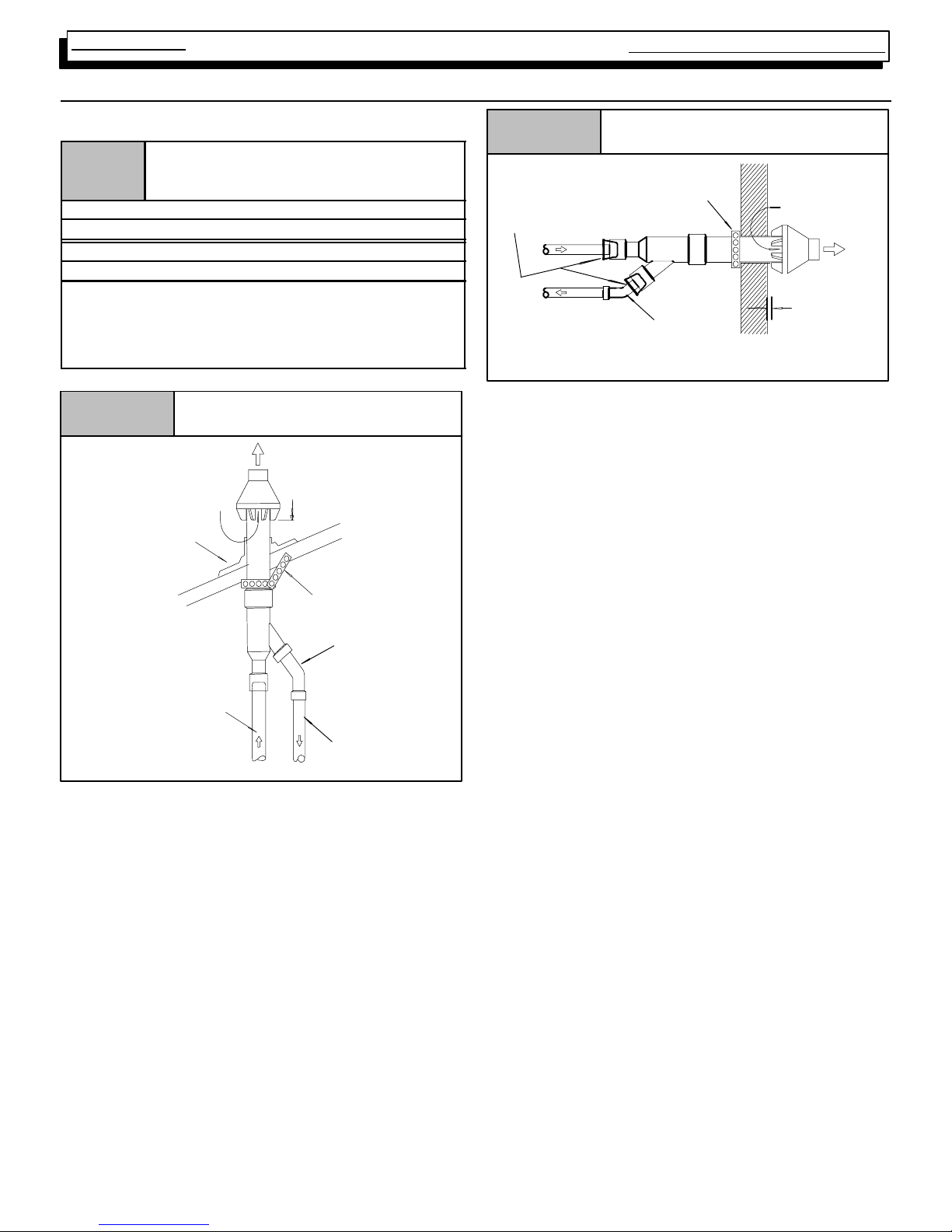
Figure 15
Pipe Diameter Table
Single Piping ONLY
Pipe Diameter Table
Dual Piping ONLY
Standard Termination
Rooftop Termination
B
Consult the appropriate Venting tables and/or piping chart
for the model (series) you are servicing.
Figure 16
Inlet is optional on
Dual Certified models
Figure 17
12²²²² Min. Grade
or Snow Level
Dimension “A” is touching or 2² maximum separation.
Figure 18
Sidewall Termination 12² or More
Above Snow Level or Grade Level
8² *
MIN.
20’
MAX
*18² Minimum for cold climates
(substained below 0° F)
Concentric Vent and Combustion-Air Roof Termination
Exhaust
Combustion
Air
“A”
Concentric Vent and Combustion-Air Sidewall Termination
25-- 00--05F
Inlet is optional on
Dual Certified models
A
A
A=12² Above roof or snow accumulation level
B=8² Min., 20¢ Maximum, except in areas with extreme
cold temperatures (sustained below 0°F), the 18² Min.
440 08 2002 02
25-- 00--06
14
1²²²² Maximum
Combustion Air
Exhaust
Ven t
Dimension “A” is touching or 2² maximum separation.
(TYP.)
Ven t
“A”
25--22--02d
Page 17
Two- Stage Multi Position Furnace
Service
Manual
Figure 19
“A”
Inlet
12²²²² Min. Grade
or Snow Level
Dimension “A” is touching or 2² maximum separation.
Figure 20
18²²²² Min. for Cold Climates
(Sustained Below 0°°°° F)
Exhaust
Sidewall Inlet Vent and Exhaust-Air Termination
Exhaust
8²²²² Min.
20¢¢¢¢ Max.
18²²²² Min. for
Cold Climates
(Sustained Below 0°°°° F)
“A”
8²²²² Min.
Sidewall Inlet Vent and Exhaust--Air
Termination with Exterior Risers
8²²²² Min.
8²²²² Min.
20¢¢¢¢ Max.
12²²²² Min.
Grade or
Inlet
Snow Level
Figure 22
FRONT VIEW
Recommended Alternate Installation for Sustained Cold Weather
(--0°°°° F & below)
OVERHANG
12²²²² MIN.
EXHAUST
90°°°°
INLET
12²²²² MIN. Ground Level
OR Snow Level
SIDE VIEW
12²²²² MIN.
25--23 --73
Figure 21
18²²²² Min. for Cold Climates
12²²²² Min.
Grade or
Snow Level
“A”
“A”
Dimension “A” is touching or 2² maximum separation.
Rooftop Inlet Vent and Exhaust-Air Termination
(Sustained Below 0°°°° F)
Inlet
8²²²² Min.
20¢¢¢¢ Max.
Exhaust
Same Joist
Space
25--22--43
440 08 2002 02
15
Page 18
Service
Manual
17. CONCENTRIC VENT TERMINATION
Two- Stage Multi Position Furnace
Vent/Combustion Air Piping Charts
Concentric Termination Kit NAHA001CV
Tab l e 6
NAHA002CV -- 35¢ & (4) 90° elbows with 2² PVC pipe
NAHA001CV -- 35¢ & (4) 90° elbows with 3² PVC pipe
1. Do not include the field supplied 45° elbow in the total elbow
count.
2. If more than four elbows are required, reduce the length of
both the inlet and the exhaust pipes five feet for each
additional elbow used.
3. Elbows are DWV long radius type for 2
Figure 23
& NAHA002VC Venting Table Dual Piping
ONLY
50,000 & 75,000 Btuh Furnaces
100,000 & 125,000 Btuh Furnace
² and 3² vents.
Concentric Vent Roof Installation
Vent
Combustion
Air
Roof Boot/
Flashing
(Field Supplied)
Maintain 12² min. clearance
above highest anticipated
snow level. Max. of 24²
above roof.
Figure 24
3² x2² Bushings or
1
/2² Bushings
3² x2
If 3² vent not used
(Field supplied)
Vent
Combustion
Air
Note:
Securing strap must be field installed to prevent movement of termination kit in side wall.
Concentric Vent Sidewall
Attachment
Strap
(Field Supplied)
45° Elbow
(Field Supplied)
Combustion
Air
Vent
Flush to
1² max.
25-- 22--02
Support
(Field Supplied)
45° Elbow
(Field Supplied)
Vent
Combustion
Air
Note:
Support must be field installed to secure termination kit to structure.
25-- 22--02
440 08 2002 02
16
Page 19
Two- Stage Multi Position Furnace
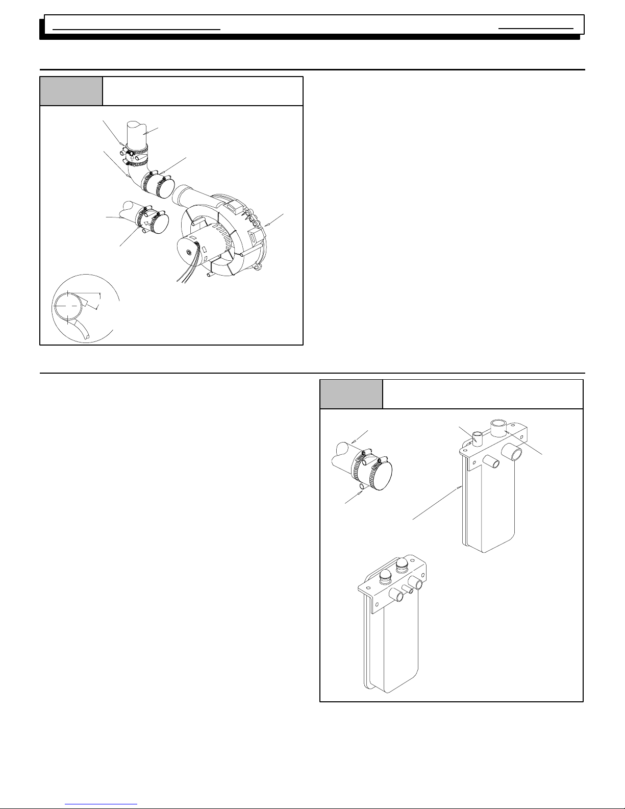
18. EXHAUST BLOWER
Figure 25
Exhaust Blower
Service
Manual
Always check the current “Technical Support Manual” for
part nos.
Vent Fitting
&Clamps
90° Elbow
Vent Pipe
(Side panel exit)
Vent Fitting
&Clamps
DRAIN SIDE VIEW
C
L
Rotate
downward
20° to 30°
Vent Pipe (Top panel exit)
Rubber Coupling & Clamps
Blower
25-- 23--35
19. CONDENSATE DRAIN TRAP
This furnace removes both sensible and latent heat from the
products of combustion. Removal of the latent heat results in
condensation of the water vapor. The condensate is removed from the furnace through the drains in the plastic transition and the vent fitting. The drains connect to the externally mounted condensate drain trap on the left or right side of
the furnace. Refer to Figure 26.
The condensate drain trap supplied with the furnace MUST
be used. The drain line between the condensate drain trap
and the drain location must be constructed of
CPVC pipe.
The drain line must maintain a
1
/4² per foot downward slope
toward the drain.
3
/4² PVC or
Figure 26 External Drain Trap
Vent Pipe
(Side panel exit)
Vent Drain Connection
Drain Line
(hidden)
Vent Drain
OLD
Transition
Box Drain
DO NOT trap the drain line in any other location than at the
condensate drain trap supplied with the furnace.
If possible DO NOT route the drain line where it may freeze.
The drain line must terminate at an inside drain to prevent
freezing of the condensate and possible property damage.
1. A condensate sump pump MUST be used if required
by local codes, or if no indoor floor drain is available.
The condensate pump must be approved for use with
acidic condensate.
2. A plugged condensate drain line or a failed condensate
pump will allow condensate to spill. If the furnace is
installed where a condensate spill could cause damage, it is recommended that an auxiliary safety switch
be installed to prevent operation of the equipment in
the event of pump failure or plugged drain line. If used,
an auxiliary safety switch should be installed in the R
circuit (low voltage) ONLY.
17
NEW
25--23--63
440 08 2002 02
Page 20

Service
Manual
Two- Stage Multi Position Furnace
20. HONEYWELL ST9162A Series FAN TIMER/FURNACE CONTROL
Figure 27
Honeywell ST9162A
The ST9162A Heating Fan“OFF” delay can be set to ei-
ther 60,100,140, or 180 seconds. The control was shipped
out in the 140 second position. This may be satisfactory for
some installations, but not for others.
The HONEYW E LL S T 9162A Electronic Fan Timer/Furnace Control is an integrated electronic control, which contains NO USER SERVICEABLE COMPONENTS. In addition to controlling the fan operation for heating, it also takes
the place of the blower relay, combustion air relay and/or
system relay.
The ST9162A is used in conjunction with the SV 9541Q
GAS VALVE/IGNITION CONTROL. It provides the power
source to begin the ignition sequence through a monitored
safety circuit. It serves as a low voltage terminal strip, and
provides accessory terminals for a Humidifier, Electronic
Air cleaner and a “Continuous” terminal which can be used
on models equipped with a Permeate Split Capacitor
(P.S.C.) motor (ONLY) to provide continuous fan operation
at a speed other than either the heating or cooling speed.
Figure 28
ON
12 34
60 Sec.
ON
1234
140 Sec.
Heating OFF Delay DIP switch Settings
ON
1234
100 Sec.
ON
1234
180 Sec.
The ST9162A Heating Fan“ON” delay may be set to ei-
ther 30 or 60 seconds. The control is shipped out at 30 seconds. As with the “OFF” delay, this may be satisfactory
for some installations, but not for others.
Figure 29
ON
Heating ON Delay DIP switch Settings
ON
The control provides a f ixed (non--adjustable) 5 second
“ON” and 60 second“OFF” delay for the circulating blower
in COO LING and an adjustable 30 or 60 second “ON”
delay for the circulating blower in HEATING.
The ST9162A control also provides an adjustable HEATING “OFF” delay for the circulating blower which can be
field adjusted to 60, 100, 140, or 180 seconds.
Setting “OFF” and “ON” delays
Setting The ST9162A Heating Fan “ON” & “OFF” Delay is
accomplished by the positioning of “DIP” switches. The illustrations Figure 28, & Figure 29, indicate how to position
these switches to obtain the desired setting.
440 08 2002 02
1234
60 Sec.
1234
30 Sec.
The “OFF” delay should be set as long as possible without
creating “COLD AIR” complaints at the end of the cycle.
The “ON” delay should be set as short as possible without
creating “COLD A I R” complaints at t he beginning of the
cycle.
The COOLING “ON” and “OFF” delays of the ST9162A
are fixed at 5 seconds and 60 seconds respectively,
and are not adjustable.
18
Page 21

Two- Stage Multi Position Furnace
Service
Manual
21. ST9162A/SV9541Q TESTING SEQUENCE
If furnace successfully passes this testing sequence, it can be assumed that there are no problems with the ST9162A/SV9541Q CONTROL SYSTEM. If it does not, however,it does not necessarily mean that there are problems with the control SYSTEM. Any malfunctions should be thoroughly
investigated before replacing any components.
CHECKING HEA TING FUNCTIONS
1. JUMPER “W
1,orW1 &W2”TO“R”
CHECKING COOLING FUNCTIONS
1. JUMPER “Y” & “G” TO “R”
2. CHECK COMBUSTION BLOWER START--UP
3. CHECK IGNITION SYSTEM ACTIVAT ION
2. CHECK COOLING FAN DELAY “ON”
4. WHEN MAIN BURNER LIGHTS, CHECK
HEATING FAN “ON” DELAY
3. CHECK COOLING SPEED FAN OPERATION
5. CHECK HEATING SPEED FAN OPERATION
6. REMOVE JUMPER
4. REMOVE JUMPER
7. CHECK POST PURGE DELAY
8. CHECK HEATING FAN “OFF” DELAY
5. CHECK COOLING FAN “OFF” DELAY
22. HONEYWELL SV9541Q 2- STAGE GAS VALVE/IGNITION CONTROL
quence. The second is a 115 volt circuit used to power the
combustion blower.
The SV9541Q system is not polarity sensitive.
The SV9541Q Ignition System Control(working in conjunction with the ST9162A fan timer) manages the Ignition Sequence, and the flow of gas to the pilot and main burners.
It is in essence a combination Gas V alve and Ignition control.
Figure 30
Pilot Burner/Sensor
Honeywell ST9541Q Ignition System
Ignition/Sensor
Manifold Pressure
Adjustment
OUTLET
Gas Valve/Ignition Control
LO
HI
INLET
The system consists basically of only two (2) components.
The Ignition System Control and the Pilot Hardware. They
operate on Two ( 2) power circuits received from the
ST9162A Fan Timer/Furnace Control. One is the 24 volt
power supply for the ignitor, and to activate the ignition se-
It contains sophisticated electronic components (internally)
and has NO USER SERVICEABLE COMPONENTS.
Should a problem be verified internally within the device,
IT IS NOT FIELD REPAIRABLE, and must be replaced.
The Pilot Hardware includes the pilot burner, the hot surface element that lights the pilot burner, the flame rod that
senses pilot flame, and the cable that attaches to the system control.
The hot surface element is made of a tough break resistant
ceramic composite material. It operates on 24 Volts A.C.
The Igniter/Flame Rod assembly can be replaced independently from the pilot burner assembly.
The hot surface igniter can be checked for resistance. A
“Good” igniter will have a resistance of 10 Ohms or less.
Flame current for this system should be 2.0 microamps or
higher. Carrier voltage for flame signal (i.e. flame rod to
valve body) is 80 volts or higher.
440 08 2002 02
19
Page 22

Service
Manual
Two- Stage Multi Position Furnace
23. HONEYWELL SV9541Q SYSTEM OPERATION & DIAGNOSTICS
The following is the normal operating sequence for the 2--stage control system.
Cooling (Y) Request:
24 VAC signals applied to Y & G terminals of EFT (electronic fan timer) control.
· Cool motor speed energized after 5 second Cool Fan On Delay time.
Y & G signals removed from EFT.
Cool motor speed de -- energized after 60 second Cool Fan Off
·
Delay time.
Cooling (Y) and dehumidification (Y2) requests:
24 VAC signals applied to Y, Y2 & G terminals of EFT (electronic fan timer) control.
·
· Same operation as the cooling (Y) request, except the cooling speed is reduced 20% to compensate for high humidity
conditions during cooling operation. The cooling speed returns to the normal setting after the Y2 signal is removed.
Circulating Fan (G) Request:
24 VAC signals applied to G terminals of EFT control.
Low motor speed energized without delay.
·
G signal removed from EFT.
Low motor speed de--energized without delay.
·
NOTE1) Furnaces with DC blower motors run a low circulating fan speed in response to G request.
NOTE2) Furnaces with PSC blower motors de--energize the Low Heat fan speed during the heat exchanger warm--up
period on a call for Heating that occurs during a G request.
NOTE3) Heating or Cooling requests received during a Fan request cause the fan speed to change to the appropriate heat
or cool speed after the selected Fan On Delay time expires. The fan returns to circulating speed after the selected Fan Off
Delay time expires following loss of the Heating or Cooling request.
Heating (W1) Request (single stage thermostat operation, 4th DIP switch must be in off position) (see furnace
wiring diagram):
24 VAC signals applied to W1 terminal of EFT control.
Inducer motor turns on at high speed.
·
· The high fire solenoid energizes.
· Followinga3secondprepurge delay, the pilot valve opens and the ignitor begins to warm up.
· After the pilot lights, the main burners energize and light (burners now at high fire rate).
· Timed from the opening of the main gas valve, the control will delay the selected Heat Fan On Delay time before
switching the inducer to low speed, de--energizing the high fire solenoid and the fan switches to Low Heat speed.
· Timed from initial application of the Heating request, if the W1 request is still present after the selected Low Fire Delay
time expires (12 minutes), the inducer switches to high speed, the high fire solenoid energizes and the fan switches to
High Heat speed.
W1 signal removed from EFT.
· The gas valve de--energizes and the main burners go out.
· The inducer runs at its present speed for a 5 second postpurge period.
· The fan switches to (or stays at) Low Heat speed.
· Timed from the gas valve de--energizing, the Low Heat fan speed de--energizes after the selected Heat Fan
Delay time expires.
NOTE4) If a new Heating request arrives while the control is
waiting in the Heat Fan Off Delay time, the fan speed switches to
High Heat until the Heat Fan Off Delay expires or the Heat Fan
On Delay expires for the new Heating request.
Heating Request (two stage thermostat operation, 4th DIP switch must be in on position) (see furnace wiring
diagram):
24 VAC signals applied to W1 terminal of EFT control.
· Same response as single stage thermostat operation described above except the control will not go to high fire, High
Heat fan speed unless a W2 signal is applied.
440 08 2002 02
20
Page 23

Two- Stage Multi Position Furnace
Service
Manual
24 VAC signals applied to W1 and W2 terminals of EFT control.
Same light--off routine as described for the signal stage thermostatoperation except that at the end of the selected Heat Fan On Delay,
·
the inducer remains on high fire, the high fire solenoid remains energized and the High Heat fan speed energizes.
NOTE5) The EFT control responds without delay to the presence or loss of W2 (with W1 constant). W1 & W2 results in high
inducer, high fire and High Heat fan speed. W1 only results in low inducer, low fire and Low Heat fan speed.
Heating Request with Gas Supply Line Shut Off:
24 VAC signals applied to W1 terminal of EFT control.
· Inducer motor turns on at high speed.
· The high fire solenoid energizes.
· Followinga3secondprepurge delay, the pilot valve opens and the ignitor begins to warm up.
· The ignitor glows red--hot for 30 seconds, then turns off.
· The igniter stays off for 25 seconds, then begins to warm--up again.
· The igniter glows red--hot for 30 seconds, then turns off.
· The pilot valve closes 3 seconds after the igniter de--energizes.
· The inducer de--energizes 5 seconds after the pilot valve closes.
· The SmartValve proceeds to soft lockout and flashes error code 6.
· The control exits soft lockout after 5 minutes and begins another ignition sequence.
Gas Valve Diagnostic Codes (See Figure 4)
OFF = Control not powered
Heartbeat = Normal Operation (Standby or call for heat)
1 Flash = Not used
2 Flashes = Low Pressure switch closed when should be open
3 Flashes = Low Pressure switch circuit was still sensed as open 30 seconds after the inducer was energized. System
is in 5 minute delay mode, with inducer off. After 5--minute delay, a new ignition sequence will be initiated.
(Note: SV9541Q On/Off switch in off position during a call for heat will generate this diagnostic code)
4 Flashes = Limit switch string open
5 Flashes = Flame sensed out of sequence -- Flame signal still present.
6 Flashes + 1 Note 1 = Soft Lockout --Maximum retry count exceeded (failed to light within 4 trials for ignition)
6 Flashes + 2 Notes 1,2 = Soft Lockout --Maximum recycle count exceeded -- Last failure was Flame Sense Lost
During Run, Cycling Pressure Switch or Blocked Condensate.
6 Flashes + 3 Notes 1,2 = Soft Lockout --Maximum recycle count exceeded -- Last failure was Airflow Proving Circuit
Opened During Run
6 Flashes + 4 Notes 1,2 = Soft Lockout --Maximum recycle count exceeded -- Last failure was Limit Circuit Opened
During Run
7 Flashes = Soft Lockout Due to Limit T rips Taking Longer than 2 minutes to Reset; Auto Reset After 1 Hour if Call
for Heat Still Present. Reset by Cycling Call for Heat at Any Time.
8 Flashes = High Pressure Switch closed when sould be open.
9 Flashes = High Pressure Switch open when sould be closed.
NOTE 1: The 6 + X designation indicates a combination of flash codes: 6 flashes shows the control is in soft lockout, followed
by X flashes to indicate the reason the control went into soft lockout. When the 6+ X code is flashing, the SV9541 will attempt
a new ignition sequence after a five minute delay period, if the call for heat is still present. Reset of the thermostat will initiate
a new ignition sequence immediately.
NOTE 2: Any combination of 5 ‘abnormal’ events during a single call for heat will result in soft lockout. An ‘abnormal’ event
is a Flame Sense Failure During Run, Airflow Proving Circuit Open During Run, or Limit Circuit Open During Run. The flash
code will indicate which was the last ‘abnormal’ event that put the system into the soft lockout state based on the table above.
440 08 2002 02
21
Page 24

Service
Manual
24. CHECKING FLAME CURRENT
The Honeywell SV9541Q Ignition system used in this furnace
series proves (verifies) flame via the Flame Rectification
method.
Flame Rectification is a process of converting Alternating
Current (A.C.) into Direct Current (D.C.) During the ignition
sequence, an alternating current (A.C.) Voltage is applied to
the Flame probe.
When the burner lights the flame conducts an electrical current between the flame probe and the burner ground. Due to
25. CAPACITORS
Figure 31
100 m¦
10 m¦
Checking Capacitor
Microfarads
5 mp
1000 m¦
10000 m¦
+
Two- Stage Multi Position Furnace
the difference in size between the flame probe and the burner ground area this current flows mostly in one direction. This
creates a pulsating Direct Current that flows back to the ignition control proving flame.
This flame current (D.C. Microamps) may be checked (while
flame is present) using a D.C. Flame Sensor kit is available
from outside vendors.
Permanent Split Capacitor (P.S.C.) motors are used on the
circulating (conditioned air) blower of 2 Speed models and
on the exhaust (combustion) blower of condensing models.
Before replacing one of these motors (assumed to be bad)
the condition of its capacitor should be verified, since it, and
not the motor, may be the source of the problem.
Note: *9MPT models use PSC motors on circulating blower
and on the 125 exhaust blower).
Before checking any capacitor, the supply power to the unit
should be turned “OFF”. The capacitor should then be discharged (through a resistor) before testing. A 20,000 Ohm
2 Watt resistor can be used for this purpose.
The condition of the capacitor should then be verified with a
capacitor analyzer (one that indicated the capacitor’s value
in microfarads) rather than with an Ohmmeter. The reason
for this, is that an Ohmmeter test can only indicate if a capacitor is “OPEN’, or “SHORTED”, it cannot verify if its value (microfarads) is within an acceptable range.
26. BLOWER ASSEMBLY
All variable Speed models use one of two different variable
speed (D.C. motor), direct--drive, blower assemblies. Different siz e (HP) motors and/or different diameter blower
wheels are used in t he different models to obt ain the r equired air flow.
All 2 Speed models use a multi--speed, permanent split capacitor mot or, direct --drive, blower ass embly. Differ ent
size (HP) motors and/or different diameter blower wheels
are used in each model to obtain the required air flow.
In all models entire blower assembly slides out on rails for
servicing after removing the two screws at the front of the
blower deck.
CHECKING BLOWER MOTOR
Variable Speed Models - D.C. Motor
The D.C. Motor used in the variable speed models Cannot
440 08 2002 02
Capacitor should test to within 10% of its rated value. Capacitors testing outside this range should be replaced. A weak
capacitor can be the cause of a motor failing to start.
be c hecked accurately using tr aditional methods. An
Ohmmeter test will tell little or nothing about the condition
of t he motor. Bec ause of this a “S pecial” test method is
required to determine if the motor is good or bad.
The condit ion of this motor can O NLY be verified as f ollows: With the thermostat calling for operation in the desired mode, and line voltage applied to the motor, Check
for 24 Volts across the “Common” (Blue) wire and the desired “Speed” wire of the six (6) pin connector at the motor.
With 24 VAC present, motor should run. If the motor Does
Not run, it is faulty and must be replaced. If 24 VAC is not
present, a problem is indicated in the thermostat, wiring, or
ST9162A.
22
Page 25

Two- Stage Multi Position Furnace
Service
Manual
Figure 32
Wire Color Motor Speed
Blue Common
White Low Heat
Green Circulating
Black High Heat
Yellow Cooling
Brown Dehum. (80%)*
* Function enabled only when energized with cooling
speed. Motor runs at 80% of cooling speed.
Figure 33
Variable Speed Models
D.C. Motor Speed Wires
Checking P.S.C. Motor
lected” for each particular installation to insure proper operation.
The criteria for selecting the proper blower speeds IS NOT
“High for Cooling, Low for Heating”. Although that may be
how it works out SOMETIMES, It can (in many cases) be
exactly the opposite. (I.E. a Lower speed for Cooling, and
a Higher speed for Heating)
The PROPER CRITERIA FOR SELECTING BLOWER
SPEEDS is as follows:
HEATING
A blower speed must be selected that will provide proper
temperature rise through the furnace. (See “checking temperature rise” f ound on page 9 of this manual). The required CFM for a particular temperature rise can also be
calculated by using the following formula:
Output BTU
Temp. Rise X 1.08 = CFM
EXAMPLE: Using a 75 M btu Non--Condensing furnace
(equipped with P.S.C. motor)of this series with an output of
60,000 Btuh and a desired temperature rise of 50 _F
(range of 35--65 _F allowable) and a measured external
static pressure of 0.2” W.C. while operating on medium-low speed with a dry coil.
60,000
50 X 1.08 59.4 = 1010 CFM
Checking the blower performance data for this model, (see
Tab l e 7) indicates that @ 0.2” W.C. E.S.P. m edium--low
speed delivers 1030 CFM . Accordingly, m edium-- low
speed is the proper speed to be used in this example for
the HEATING speed.
or 60,000
+
2 Speed Models - P.S.C. Motor
The P.S.C. motor used in 2 speed models may be checked
using traditional Ohmmeter test methods. I.E. Checking
from any speed tap lead (black, orange, blue, or r ed) to
Neutral (white) should indicate continuity. While checking
from any motor lead to the motor case should indicate infinity (no continuity). Before condemning any P. S . C . m o t o r
be sure to verify the condition of its capacitor.
SELECTING BLOWER SPEEDS
The wide variet y of applications and inst allat ions of furnaces throughout the country makes it impossible to “Factory Select” blower speeds that will provide proper operation for all installations. This means then, that the blower
speeds for both heating and cooling must be “F ield Se-
COOLING
A blower speed must be selected that will provide proper
air flow (Nominal 400 CFM per ton) for the size (capacity)
air conditioning coil being used at the external static pressure of the Duct syst em (installation). This r equires
CHECKING THE EXTERNA L STATIC PRESSURE, and
then consulting the BLOWER PERFORMANCE DA TA to
determine the required speed tap.
EXAMPLE: A 24,000 BTU (2 ton) air conditioning system,
using the same 75,000 BTU furnace as in the previous example. The external static pressure is measured with the
unit operat ing on Low speed, and found to be 0.4” W.C.
with a wet coil.
400 CFM (nominal) per ton required
400 X 2 = 800 CFM required
Checking t he blower performanc e data (see Table 7)for
this m odel indicates that @ 0.4” W.C. ESP low speed is
delivering 735 CFM. Accordingly, low speed is the proper
speed to be used in this example for the COOLING speed.
440 08 2002 02
23
Page 26

Service
s
P
W
t
s
nIn
x
Manual
Two- Stage Multi Position Furnace
Tab l e 7
Always check current “Technical Support Manual”
Blower Performance Data 75,000
BTUH (PSC Motor)
Air Delivery in Cubic Feet per Minute (CFM)
(Furnace Rated @ 0.5² W.C. ESP)
TAP LOW MED L MED H HIGH
.10 706 917 1163 1368
.20 677 875 1120 1319
.30 636 840 1076 1263
sure
.40 595 812 1031 1202
Pres
W.C.
.50 546 766 987 1148
sof
tatic
.60 490 702 889 1077
al S
nche
.70 -- -- -- 630 821 989
xter
E
.80 -- -- -- 550 750 914
.90 -- -- -- 462 676 833
1.0 -- -- -- -- -- -- 601 747
EXTERNAL STATIC PRESSURE (ESP)
External Static Pressure can best be defined as the pressure difference (drop) between the Positive Pressure (discharge) and the Negative Pressur e (intake) sides of the
blower. E xter nal St atic Pressure is developed by t he
blower as a result of resistance to airflow (Friction) in the
air distribution system EXTERNAL to the furnace cabinet.
(i.e pressure inside duct)
Resistance applied externally to the furnace (I.E. Duct
work, Coils, Humidifiers, Filters, Etc.) on either the Supply
or Return side of the system, causes an INCREASE in External Static Pressure, accompanied by a REDUCTION in
airflow.
ESP is affected by two (2) factors.
1. Resistance to Airflow as explained above.
2. Blower Speed. Changing to a higher or lower blower
speed tap will raise or lower the External Static Pressure accordingly.
These effects MUST be understood and taken into consideration when checking ESP/ Airflow to insure that the system is operating within design conditions.
Operating a system with Insufficient or Excessive air flow
can cause a variety of different operating problems.
Among t hese are prem at ure heating com ponent and/ or
compressor failures, reduced capacity, freezing evaporator coils, etc.
System air flow should ALWAYS be verified upon completion of a new installation, or BEFORE a change--out, heat
exchanger replac ement , or in the case of a compressor
failure to insure that the failure was not caused by improper air flow.
Figure 34
Indoor
Section
Checking Static Pressure
Supply
Inclined
Manometer
Return
CHECKING EXTERNAL STATIC PRESSURE
The air flow through the unit can be determined by measuring the external static pressure of the system, and consulting
the blower performance data for the particular model furnace
you have.
1. Set up to measur e external st at ic press ure at t he supply and r et urn duct connections (See F igure 34).
2. Drill holes in the ducts for pressure taps, pitot tubes, or
other accurate pressure sensing devices.
3. Connect these taps to a level inclined manometer or
Magnehelic gauge.
4. Ensure the coil and filter are clean, and all the registers
are open.
5. Determine the external static pressure with the blower
operating.
6. Refer to the Air Flow Data for your particular furnace to
find the actual airflow for the current speed tap (or dip
switch setting).
7. If the Actual airflow is either too high, or too low, the
blower speed tap (or dip switch setting) will need to be
changed.
8. Refer to Changing Blower Speeds on the pages that follow for the proper procedure.
9. Select the speed tap (or dip switch setting) that appears to most closely provide the required air flow for
the system.
10. Recheck the external static pressure with the new
speed tap. External static pressure (and actual airflow) will both have changed (either higher, or lower),
depending upon speed tap selected. Recheck the actual airflow (at this “new” static pressure) to confirm
speed tap selection.
1 1. Repeat steps 9. and 10. (if necessary) until proper
Speed Tap (and airflow) has been obtained.
440 08 2002 02
24
Page 27

Two- Stage Multi Position Furnace
Figure 35
Thermometer:
Return Air
Tem p .
Return
Checking Temperature Rise
Air Flow
Thermometer;
Supply Air Temp.
3¢ min from radiant scene
Supply
Service
Manual
NOTE: T his same method can be us ed (on models
equipped with a P.S.C. motor)to determine the COOLING
airflow, by TEM PO RA RI LY connecting the cooling speed
tap wire to the HEAT terminal of the FAN Control. NEVER
connect two (2) speed tap wires to the same terminal. Doing so will cause motor failure.
VARIABLE SPEED MODELS - D.C. MOTOR
The heating, cooling and circulating blower speeds can be
adjusted by changing the switch settings that are located
on the side of the blower motor (see Figure 36). Switches
#1 and #2 adjus t the circulat ing blower speed. Switches
#3, #4 and #5 adjust the heating speeds. Switches #6, #7
and #8 adjust the cooling speed. See the Technical Service
Data Sheet for t he model y ou are s erv icing to obtain the
switch settings for the desired airflow rates.
Air Flow
CHECKING APPROXIMA TE AIR FLOW
If an inclined manometer or Magnehelic gauge IS NOT
available to check the External St at ic Pressure, OR the
blower performance data is unavailable for your furnace,
approximate air flow canbecalculatedbyMeasuring the
temperature rise, then using the following criteria:
The approximate CFM actually being delivered can be calculated (if the OUTPUT Btu of the furnace is known) by operating the system in HEATING, and using the following
formula:
Output BTU
Temp.Risex1.08=CFM
EXAMPLE: Using a (75 Mbtu Input) furnace with an OUTPUT of 59,000 Btuh and a measured temperature rise of
50_F.
59,000
50 x 1.08 54 = 1093 CFM
or 59,000
CHANGING BLOWER SPEEDS
The procedure for changing blower speeds (if needed) differs based on whether the unit is a variable speed model,
or a 2 speed model.. (See Figure 36 and Figure 38 and
the appropriate sections for the model you are servicing).
!
Electrical shock hazard.
Turn OFF power to furnace before changing
blower speeds.
Failure to do so can result in personal injury
and/or death.
VARIABLE SPEED MODELS - D.C. MOTOR
The heating, cooling and circulating blower speeds can be
adjusted by changing the switch settings that are located
on the side of the blower motor (see Figure 36). Switches
#1 and #2 adjus t the circulat ing blower speed. Switches
#3, #4 and #5 adjust the heating speeds. Switches #6, #7
and #8 adjust the cooling speed. See the Technical Service
Data Sheet for t he model y ou are s erv icing to obtain the
switch settings for the desired airflow rates.
440 08 2002 02
25
Page 28
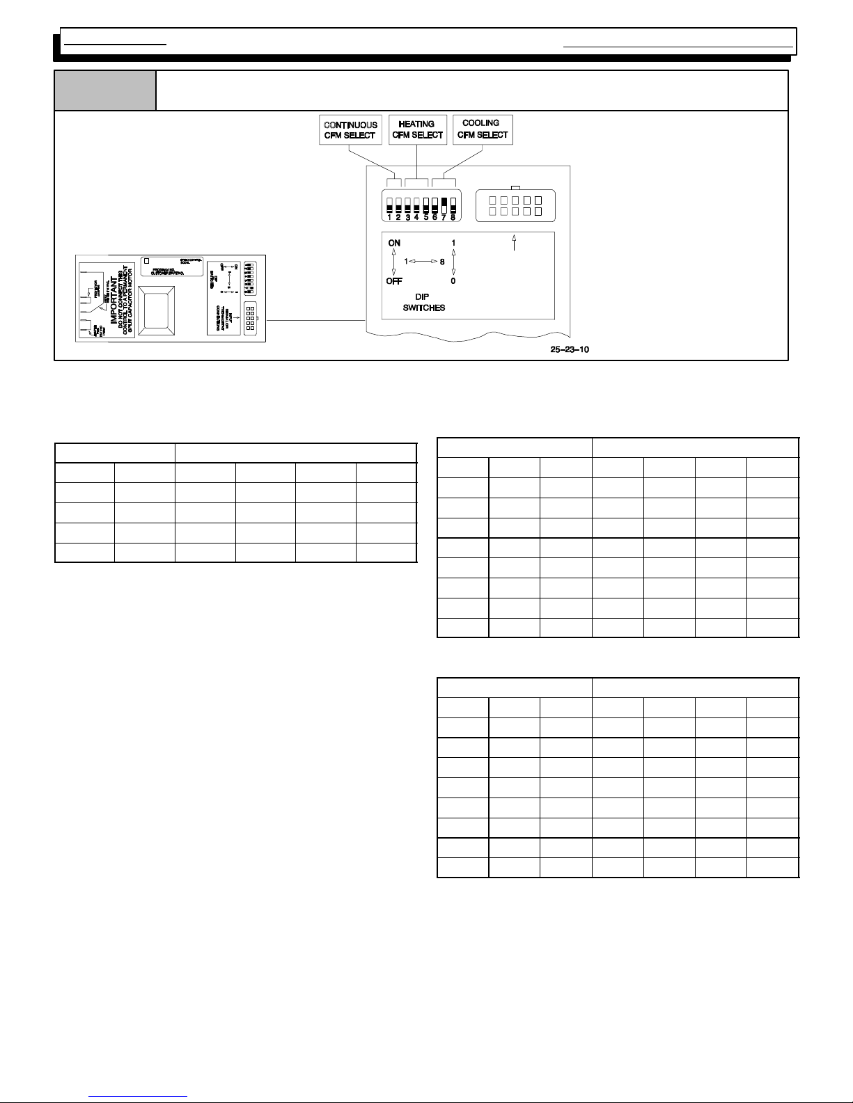
Service
Manual
Two- Stage Multi Position Furnace
Figure 36
Blower Motor Control
010
*EXAMPLE
Cooling Airflows Switches
6, 7 & 8:
INPUT
SIGNAL OR
THERMOSTAT
CONNECTIONS
000 3.5 Ton
001 3.0 Ton
010 2.5 Ton
011 2.0 Ton
*See “Technical Support
Manual” for correct airflow
rates.
NOTE: Power must be completely OFF to unit any time switch settings are changed or settings will not take effect.
Heating, Cooling & Continuous Airflow Settings
Continuous Blower (CFM) @ 0.10²²²² Static
Switch Settings
#1 #2 50K 75K 100K 125K
0* 0* 540 540 700 703
0 1 660 660 860 821
1 0 780 780 1020 1000
1 1 900 900 1180 1160
Furnace Model
*Factory Setting
#3 #4 #5 50K 75K 100K 125K
0** 0** 0** 0 0 0 0
0 0 1 1 1 1 6
0 1 0 4 2 2 8
0 1 1 7 3 5 12
1 0 0 11 6 8 16
1 0 1 -- 7 -- 4 -- 5 -- 1
1 1 0 -- 1 1 -- 6 -- 9 -- 4
1 1 1 -- 1 5 -- 9 -- 1 1 -- 7
*Factory setting
#3 #4 #5 50K 75K 100K 125K
0** 0** 0** 0 0 0 0
0 0 1 3 2 3 2
0 1 0 6 4 5 6
0 1 1 14 6 9 11
1 0 0 17 11 13 13
1 0 1 -- 8 -- 4 -- 4 -- 5
1 1 0 -- 1 3 -- 4 -- 7 -- 5
1 1 1 -- 1 7 -- 4 -- 9 -- 5
*Factory setting
**Approximate air temperature change from factory setting
@0.20² static on high heat ).
Lo Heat Air Temperature Adjustment (°°°° F)**
Switch Settings
Hi Heat Air Temperature Adjustment (°°°° F)**
Switch Settings
Furnace Model
Furnace Model
440 08 2002 02
26
Page 29

Two- Stage Multi Position Furnace
2 SPEED MODELS - P.S.C. M OTOR
HEATING SPEEDS
Should it be necessary to change blower speeds to obtain
proper temperature rise on either (or both) High fire, and/or
Low Fire, Simply take the appropriate speed tap wire, and
plug it on to the terminal marked “HEAT HIGH” or “HEAT
LOW” respectively on the HONEYWELL ST9162A control.
Service
Manual
connection to the control. Their purpose is to provide a
place to connect, or “PARK” any “UNUSED” speed tap
wires (P.S.C. motors ONL Y) to keep them out of the way
and pr event them from shorting out against the furnace
casing, or each other.
Figure 38
Honeywell ST9162
Figure 37
2 Speed Models
Blower Speed Taps
Wire Color Motor Speed
Black High
Orange Medium--High
Blue Medium--Low
Red Low
COOLING SPEED
When the proper speed has been determined, simply plug
it on to the terminal marked ”COOL” on the HONEYWELL
ST9162A control.
“M1 ” & “M2 ” TERMINALS
There are two (2) terminals (marked “M1” & “M2”) on the
HONEYWELL ST9162A control which have no internal
27. BLOWER ROTATION
· The startup of a furnace will involve a cycle or two of the furnace to properly prime the condensate trap with water. Until
the trap is fully primed, some condensate will be pulled into
the combustion blower. The furnace may cycle on the pressure switch connected to the plastic transition box due to condensate buildup. After the trap is primed, the condensate will
start draining from the furnace. The combustion blower will
clear out any remaining condensate in the blower housing
through the vent fitting downstream of the blower. Note that
the condensate trap can also be primed by pouring water into
the vent drain side of the trap. Remove the small plastic cap
and clamps from the unused drain stub on the vent drain side
of the condensate trap. Connect a section of the
with a funnel to the drain stub and pour eight (8) ounces of water into the trap. Remove the hose and replace the plastic cap
and clamp. This will prime both the vent and the transition
sides of the trap.
· The startup of a furnace will have “milky or oily”. looking condensate coming from the furnace. This is residual drawing
lube in the secondary heat exchanger that is being washed
out by the condensate. The condensate will clear up as the
5
/8² OD hose
M1 & M2 Terminals
Cooling
Terminal
Heating
Terminals
Dip Switch
Y2 Terminal
furnace operates. Poisonous carbon monoxide gas hazard.
· The use of a vent tee at the outlet of the condensate trap is not
required if the condensate drain line from the trap to the open
drain is properly sloped (
not trap the drain line in any other location than at the condensate trap.
· The combustion blowers and blower gaskets are different on
some of the furnace models. There are two part numbers of
the combustion blower for the 2--stage furnace models. (See
the Tech. Manual for the correct part number for the furnace.)
Besides the part number difference, the 50M, 75M and 100M
BTUH models use the shaded pole motor version with the
7
1
/8² diameter back plate with a raised lip. The blower gasket
is approximately 2
the recessed opening in the transition. The 125M BTUH models use the PSC motor version with the 2² diameter back plate
with no lip. The blower gasket is approximately 3
diameter and is positioned on the flat surface of the transition.
A mismatch of blower backplated and/or gaskets can cause
the furnace to cycle on the pressure switch or to not operate.
This could be misread as a condensate drainage problem.
1
/4² per foot downward slope). Do
3
/4² outside diameter and is positioned into
1
/4² outside
440 08 2002 02
27
Page 30

Service
Manual
Two- Stage Multi Position Furnace
Figure 39
Supply Air
Vent Pipe Grommet
Vent Fitting & Clamps
GasPipeGrommet
Rubber Plug
90°°°° Elbow
Rubber Cou pling
&Clamps
5
/8²²²² Hose & Clamps
Combustion Blower
Plastic Caps
Condensate
Trap & Gasket
(Left or Right Side)
Drain Line
25-- 23--53a
Upflow Installations (Dual Certified *9MPT & *9MPV(A1) Models)
Vent Pipe
LEFT Side Venting
Inlet
Exhaust
AIRF LOW
3
/4²²²² Hose
&Clamps
Combustion
Blower
Mounting
Screws (4)
Pressure Switch,
Transition
(Lo Fire)
Combustion
Air Pipe (optional)
Air Intake Couplin g
Plastic Caps
Pressure Switch
Hose, Blower
Pressure Switch Hose,
Transition
Pressure Switch,
Blower (Hi Fire)
Transition Box
Return Air
DRAIN SIDE VIEW
Rigid Plastic
Drain Tube
Rotate
downward
20° to 30°
RIGHT Side Venting
clamp
Rigid
Plastic
Drain
Tube
Rubber
Hose
Rubber
Inlet
Exhaust
clamp
Hose
25--23--53b
Upflow Installations - (Dual Certified *9MPT & *9MPV) (See Figure 39)
Mount the condensate drain trap in a vertical position to either the
left or right side of the furnace using the two screws and gasket that
are provided. If needed, remove the hole plugs from the furnace
side panel and relocate to the open set of holes in the opposite side
panel. Drill two
7
/64² diameter holes in the casing using the conden-
sate trap as the template.
Ensure that the vent fitting and the 90° elbow is securely attached to
the combustion blower.
This configuration allows left side venting from the furnace. If right
side venting is required, the c ombustion blower must be relocated
on the plastic transitionbox. Remove the four(4) screws that secure
the blower to the transition. Rotate the blower 180° and secure with
the four(4) screws. Use caution to not over tighten the screws to prevent stripping out of the plastic mounting holes.
For right side venting, remove vent fitting assembly from combustion blower. Remove 90° elbow and rubber tubing from the vent fitting by loosening the c lamp on the vent fitting. Securely attach vent
fitting directly to combustion blower.
NOTE: The vent fitting MUST be installed with the airflow marking
arrow pointed toward the vent pipe, with the drain stub at a 20° to
30° downward slope.
Plug the right drain stub of the vent fitting with the rubber plug. Use a
blunt pointed screwdriver to push the plug into the stub.
For left side mounted condensate trap, connect the
hose with the 90° bend to the drain stub on the bottom of the plastic
transition box and secure with a
Route the hose to the large drain stub on the condensate trap. Cut
off excess hose and discard. Connect the hose to the drain stub on
the trap and secure with a
For right side mounted condensate trap, the rigid plastic drain
tube MUST be used. Cut two 2 ² long sections from the
ber hose. Connect the plastic drain tube to the drain stub on the bottom of the plastic transition box and to the stub on the condensate
trap using the two hose sections and
NOTE: The support leg on the plastic drain tube MUST be positioned on the blower partition.
5
Connect the
/8² OD rubber hose with the 90° bend to the left drain
stub on the vent fitting and secure with a
Route the hose to the small drain stub on the condensate trap. Cut
off excess hose and discard. Connect the hose to the drain stub on
the trap and secure with a
NOTE: Ensure hoses maintain a downward slope to the condensate trap with no kinking or binding for proper condensate drainage.
3
/4² clamp.
3
/4² clamp.
5
/8² clamp.
3
/4² clamps.
5
/8² clamp.
3
/4² OD rubber
3
/4² OD rub-
440 08 2002 02
28
Page 31

Two- Stage Multi Position Furnace
Service
Manual
Figure 40
Vent Pipe
Supply
Air
Ven t Pip e
Grommet
DRAIN SIDE VIEW
Exhaust
Horizontal Left Installations (Dual Certified *9MPT & *9MPV(A1) Models)
Pressure Switch Hose,
Blower
Pressure Switch,
Blower (Hi Fire)
Pressure Switch,
Transition (Lo Fire)
Combustion
Blower
Combustion Blower
Mounting Screws
(4)
Pressure Switch Hose,
Transition
3
/4²²²² Hose & Clamps
Plastic Caps
Inlet
Vent Fitting
&Clamps
Combustion Air Pipe, (optional)
Air Intake Couplin g
Rubber
Plug
Gas Pipe
Grommet
Plastic Caps
90°°°° Elbow
Condensate
Trap & Gasket
5
/8²²²² Hose & Clamps
Transition Box
Return
Air
Rotate downward
20° to 30°
Rubber Coupling
&Clamps
Drain Line
Horizontal Left Installations - (Dual Certified *9MPT & *9MPV) (See Figure 40)
Relocate the plastic caps and clamps on the condensate drain trap
from the vertical drain stub to the horizontal drain stubs. Secure the
clamps tightly to prevent condensate leakage.
Mount the condensate drain trap in a vertical position to the left side
of the furnace using the two screws and gasket that are provided.
Note: The condensate trap willbe located under the furnacein a verticalposition when the furnace is placed horizontally on the left side.
If needed, remove the hole plugs from the furnace side panel and
relocate to the open set of holes in the opposite side panel. Drill two
7
/64² diameter holes in the casing using the condensate trap as the
template.
Ensure that the vent fitting and the 90° elbow is securely attached to
the combustion blower.
NOTE: The vent fitting MUST be installed with the airflow marking
arrowpointed toward the vent pipe, with the drain stub at a 20° to 30°
downward slope.
Plug the upper drain stub on the vent fitting with the rubber plug. Use
a blunt pointed screwdriver to push the plug into the stub.
3
Connect the
/4² OD rubber hose with the 90° bend to the drain stub
on the bottom of the plastic transition box and secure with a
clamp.
Route the hose to the large drain stub on the condensate trap. Cut
off excess hose and discard. Connect the hose to the drain stub on
the trap and secure with a
Connect the
5
/8² OD rubber hose with the 90° bend to the small drain
3
/4² clamp.
stub on the trap and secure with a
Route the hose to the lower drain stub on the vent fitting. Cut off excess hose and discard. Connect the hose to the drain stub on the
vent fitting and secure with a
5
/8² clamp.
NOTE: Ensure hoses maintain a downward slope to the condensate trap with no kinking or binding for proper condensate drainage.
5
/8² clamp.
dwg 25-- 23--54a
3
/4²
440 08 2002 02
29
Page 32

Service
Manual
Two- Stage Multi Position Furnace
Figure 41
Return
Air
Horizontal Right Installations (Dual Certified *9MPT & *9MPV)
Vent Fitting
Rubber Coupling & Clamps
5
/8²²²² Hose & Clamps
Combustion
Blower
Combustion Blower
Mounting
Screws (4)
Pressure Switch
Hose, Transition
Pressure Switch, Transition
(Lo Fire)
Plastic Caps
Plastic Caps
90°°°° Elbow
Pressure Switch,
Blower (Hi Fire)
&Clamps
Rubber Plug
Transition Box
Pressure Switch
Hose, Blower
Vent Pipe
Gas Pipe
Grommet
DRAIN SIDE VIEW
Exhaust
Vent Pipe
Grommet
Inlet
Air Intake
Coupling
Combustion
Air Pipe
(Optional)
Supply
Air
Condensate Trap
& Gasket
Drain Line
3
/4²²²² Hose & Clamps
Horizontal Right Installations - (Dual Certified *9MPT & *9MPV) (See Figure 41)
Relocate the plastic caps and clamps on the condensate drain trap
from the vertical drain stub to the horizontal drain stubs. Secure the
clamps tightly to prevent condensate leakage.
Mount the condensate drain trap in a vertical position to the right
side of the furnace using the two screws and gasket that are provided. Note: The condensate trap will be located under the furnace
in a vertical position when the furnace is placed horizontally on the
right side. If needed, remove the hole plugs from the furnace side
panel and relocated to the open set of holes in the opposite side
panel. Drill two
7
/64² diameter holes in the casing using the conden-
sate trap as the template.
Ensure that the vent fitting and the 90° elbow is securely attached to
the combustion blower.
NOTE: The vent fitting MUST be installed with the airflow marking
arrow pointed toward the vent pipe, with the drain stub at a 20°
downward slope.
Plug the upper drain stub on the vent fitting with the rubber plug. Use
a blunt pointed screwdriver to push the plug into the stub.
Remove the pressure switch hose from the upper stub on the plastic
transition box.
Relocate the plastic caps on the stubs of the plastic transition box
from the lower stubs to the upper stubs and secure tightly with the
clamps.
Route the pressure switch hose to the lower stub on the plastic transition box. Cut off excess hose and discard. Connect the pressure
switch hose to the lower stub on the plastic transition box. NOTE:
Failure to correctly install the pressure switch hose to the transition
can adversely affect the safety control operation.
3
Connect the
/4² OD rubber hose with the 90° bend to the drain stub
on the bottom of the plastic transition box and secure with a
clamp.
Route the hose to the large drain stub on the condensate trap. Cut
off excess hose and discard. Connect the hose to the drain stub on
the trap and secure with a
Connect the
5
/8² OD rubber hose with the 90° bend to the lower
3
/4² clamp.
drain stub on the vent fitting and secure with a
Route the hose to the smaller drain stub on the condensate trap.Cut
off excess hose and discard. Connect the hose to the drain stub on
the trap and secure with a
5
/8² clamp.
NOTE: Ensure hoses maintain a downward slope to the condensate trap with no kinking or binding for proper condensate drainage.
Rotate downward
20° to 30°
dwg 25-- 23--55a
5
/8² clamp.
3
/4²
440 08 2002 02
30
Page 33

Two- Stage Multi Position Furnace
Service
Manual
Figure 42
Inlet
DRAIN SIDE VIEW
Rotate downward
20° to 30°
Downflow Installations (Dual Certified *9MPT & *9MPV Models(A1) Models)
LEFT Side Venting
Return Air
Combustion Blower
Mounting Screws (4)
Exhaust
Supply Air
Pressure Switch,
Transition
(Lo Fire)
Pressure Switch
Hose, Transition
Pressure Switch,
Blower
(Hi Fire)
Pressure Switch
Hose, Blower
3
/4²²²² Hose
&Clamps
5
/8²²²² Hose &
Clamps
RIGHT Side Venting
Return Air
Combustion Blower
(Rotate 180°°°° for Left Side)
Rubber
Transition
Box
Supply Air
Plug
Plastic
Caps
Air Intake
Coupling
Combustion
Air Pipe, (Optional)
Ven t Pip e
Inlet
Vent Fitting
Exhaust
&Clamps
Ven t Pip e
Grommet
Plastic
Caps
Condensate
Trap & Gasket
Gas Pipe
Grommet
Drain Line
Downflow Installations - (Dual Certified *9MPT & *9MPV Models) (See Figure 42)
Mount the condensate drain trap in a vertical position to either the
right or left side of the furnace using the two screws and gasket that
are provided. If needed, remove the hole plugs from the furnace
side panel and relocated to the open set of holes in the opposite side
panel. Drill two
7
/64² diameter holes in the casing using the conden-
sate trap as the template.
Ensure that the vent fitting is securely attached to the combustion
blower using the clamp.
NOTE: The vent fitting MUST be installed with the airflow marking
arrow pointed toward the vent pipe, with the drain stub at a 20° to
30° downward slope.
For right side venting, remove vent fitting assembly from combustion blower. Remove 90° elbow and rubber tubing from the vent fitting by loosening the c lamp on the vent fitting. Securely attach vent
fitting directly to combustion blower.
This configuration allows right side venting from the furnace. If the
left side venting is required, the combustion blower must be relocated on the plastic transition box. Remove the three(4) screws that
secure the blower to the transition. Rotate the blower 180° and secure with the three(3) screws. Use caution to not over tighten the
screws to prevent stripping out of the plastic mounting holes.
Plug the upper drain stub on the vent fitting with the rubber plug. Use
a blunt pointed screwdriver to push the plug into the stub.
Remove the pressure switch hose from the upper stub on the plastic
transition box.
Relocate the plastic caps on the stubs of the plastic transition box
from the lower stubs to the upper stubs and secure tightly with the
clamps.
Route the pressure switch hose to the lower stub on the plastic transition box. Cut off excess hose and discard. Connect the pressure
switch hose to the lower stub on the plastic transition box. NOTE:
Failure to correctly install the pressure switch hose to the transition
box can adversely affect the safety control operation.
3
Connect the
/4² OD rubber hose with the 90° bend to the drain stub
on the bottom of the plastic transition box and secure with a
clamp.
Route the hose to the large drain stub on the condensate trap. Cut
off excess hose and discard. Connect the hose to the drain stub on
the trap and secure with a
Connect the
5
/8² OD rubber hose with the 90° bend to the lower stub
3
/4² clamp.
on the vent fitting and secure with a
Route the hose to the smaller stub on the condensate trap. Cut off
excess hose and discard. Connect the hose to the drain stub on the
trap and secure with a
5
/8² clamp.
NOTE: Ensure hoses maintain a downward slope to the condensate trap with no kinking or binding for proper condensate drainage.
5
/8² clamp.
dwg 25-- 23--56a
440 08 2002 02
3
/4²
31
Page 34

Service
Manual
Two- Stage Multi Position Furnace
Figure 43
Yellow Plastic Cap
Vent Fitting
&Clamps
AIR FLOW
Condensate Trap & Gasket
(Left or Right Side)
Upflow Installations (Dual Certified *9MPT & *9MPV--A2 Models)
NOTE: TRAP MUST BE PRIMED BEFORE OPERATION
TOP Venting
Vent Pipe
Supply
Air
Inlet
Rubber Coupling &
Clamps
Combustion Blower
Mounting Screws (4)
Combustion Blower
Trap Connection
Vent Pipe Grommet
11²²²² Section PVC Pipe
Gas Pipe
Grommet
90°°°° Street
Elbow
5
/8²²²² Hose &
Clamps
Plastic Cap
“Clamp ears”
Pointed OUT
Exhaust
3
/4²²²² Hose
&Clamps
AIR FLOW
Transition
Box
Pressure Switch,
Transition
Combustion Air
Pipe (optional)
Air Intake
Coupling
Plastic Cap
Some Models have
one pressure switch
Pressure Switch
Hose, Blower
Pressure Switch, Blower
Pressure Switch
Hose, Transition
Return Air
Drain Line
Preassemble &
insert into furnace
Upflow Installations - (Dual Certified *9MPT & *9MPV) (See Figure 43)
Note: For easier installation of the drain hoses and clamps to the
condensate trap, follow the directions outlined below except do not
make any clamp connections to any of the drain stubs and hoses
until the hose routing and lengths have been determined. Remove
the condensate trap and drain hoses from the furnace and secure
the drain hoses to the drain stubs on the trap with the hose clamps
(position the clamps as shown in Figure 43). Install the condensate
trap/hose assembly to the furnace casing. Hook one side of the
“clamp ears” on the drain stub through the hole in the casing and
push the condensate trap into position. Secure with the two screws.
Reconnect the drain hoses to the stubs on the vent fitting and the
plastic transition and secure with the clamps.
Mount the condensate drain trap in a vertical position to either the
left or right side of the furnace using the two screws and gasket that
are provided. If needed, remove the hole plugs from the furnace
side panel and relocate to the open set of holes in the opposite side
panel.
NOTE: All gaskets and seals must be in place for sealed combustion applications.
440 08 2002 02
Ensure that the vent fitting and the 90° street elbow are securely attached to the combustion blower using the clamps.
Plug the upper drain stub on the vent fitting with the yellow plastic
cap.
Glue the 11² section of PVC pipe to the 90° street elbow after checking the fit up. (Follow the procedures outlined in the Joining Pipe and
Fittings section of this manual, page 30.) The PVC pipe will extend
through the top panel about 1
the end of the 11² section of PVC pipe using the clamp.
Note: There will be some misaligment of the PVC pipe inside the furnace. The rubber coupling will straighten out the misalignment at
the vent pipe connection at the top of the furnace.
For left side venting, remove 90° street elbow from the vent fitting by
loosening the clamp on the vent fitting. Securely attach vent fittingto
combustion blower.
NOTE: For left side venting, the vent fitting MUST be installed with
the airflow marking arrow pointed toward the vent pipe, with the
drain stub at a 20° to 30° downward slope.
1
². Connect the rubber coupling to
/2
32
Page 35

Two- Stage Multi Position Furnace
Service
Manual
This configuration allows left side venting from the furnace. If right
side venting is required, the c ombustion blower must be relocated
on the plastic transitionbox. Remove the four(4) screws that secure
the blower to the transition. Rotate the blower 180° and secure with
the four(4) screws. Use caution to not over tighten the screws to prevent stripping out of the plastic mounting holes.
NOTE: For right side venting, the vent fitting MUST be installedwith
the airflow marking arrow pointed toward the vent pipe, with the
drain stub at a 5° to 10° downward slope. (See Figure 44)
Plug the upper drain stub on the vent fitting with the yellow plastic
cap.
Figure 44
Upflow Installations (Dual Certified *9MPT & *9MPV--A2 Models)
RIGHT Side Venting
Supply Air
Inlet
NOTE: TRAP MUST BE PRIMED BEFORE OPERATION
Some Models
have one
pressure switch
Vent
Drain
For left side mounted condensate trap, connect the
hose with the 90° bend to the large drain stub on the condensate
trap and secure with a
3
/4² clamp.
3
/4² OD rubber
Route the hose to the drain stub on the bottom of the plastic transition box. Cut off excess hose and discard. Connect the hose to the
drain stub on the transition and secure with a
For right side mounted condensate trap, connect the
hose with the 90° bend to the bottom of the plastic transition box and
secure with a
3
/4² clamp.
3
/4² clamp.
3
/4² OD rubber
Route the hose to the large drain stub on the condensate pump. Cut
off excess hose and discard. Connect the hose to the drain stub on
the condensate trap and secure with a
3
/4² clamp.
Exhaust
DRAIN SIDE VIEW
Rotate downward
5°°°° to 10°°°°
oo
For left or right side mounted condensate trap, the pressure tap
on the condensate trap MUST be connected to the unused pressure tap located on the upper right hand corner of the plastic transition box. Remove the plastic caps from the pressure taps on the
condensate trap and the plastic transitionand connect with the
5
/16²
OD rubber hose. (See Figure 43 and Figure 44)
Connect the
5
/8² OD rubber hose with the 90° bend to the lower
Trap Connection
“Clamp ears”
Pointed OUT
Return
Air
Preassemble
25--24--00
drain stub on the vent fitting and secure with a
and insert
into furnace
5
/8² clamp.
Route the hose to the small drain stub on the condensate trap. Cut
off excess hose and discard. Connect the hose to the drain stub on
the trap and secure with a
5
/8² clamp.
NOTE: Ensure hoses maintain a downward slope to the condensate trap with no kinking or binding for proper condensate drainage.
440 08 2002 02
33
Page 36

Service
Manual
Two- Stage Multi Position Furnace
Figure 45
Ven t Pip e
Supply
Air
Vent Fitting
&Clamps
Horizontal Left Installations (Dual Certified *9MPT & *9MPV--A2 Models)
Combustion Air
Pipe, (optional)
Exhaust
Vent Pipe
Grommet
Air Intake
Coupling
Inlet
Yellow
Plastic
Cap
AIR FLOW
5
/8²²²² Hose
&Clamps
Condensate
Trap & Gasket
Pressure Switch
Hose, Blower
Some Models
have one
pressure switch
Plastic Cap
Plastic
Cap
Drain
Line
11²²²² Section
PVC Pipe
Gas Pipe
Grommet
NOTE: TRAP MUST BE PRIMED BEFORE OPERATION
Transition Box
90°°°° Street
Elbow
Pressure Switch,
Blower
Rubber
Coupling & Clamps
Combustion
Blower
Combustion Blower
Mounting Screws
(4)
Pressure Switch Hose,
Transition
3
/4²²²²
Hose & Clamps
Horizontal Trap Connection
Pressure Switch,
Transition
Return
Air
dwg 25-- 24--00b
“Clamp ears”
Pointed OUT
Preassemble and
insert into furnace
Horizontal Left Installations - (Dual Certified *9MPT & *9MPV- A2 Models) (See Figure 45)
Note: For easier installation of the drain hoses and clamps to the
condensate trap, follow the directions outlined below except do not
make any clamp connections to any of the drain stubs and hoses
until the hose routing and lengths have been determined. Remove
the condensate trap and drain hoses from the furnace and secure
the drain hoses to the drain stubs on the trap with the hose clamps
(position the clamps as shown in Figure 45). Install the condensate
trap/hose assembly to the furnace casing. Hook one side of the
“clamp ears” on the drain stub through the hole in the casing and
push the condensate trap into position. Secure with the two screws.
Reconnect the drain hoses to the stubs on the vent fitting and the
plastic transition and secure with the clamps.
Relocate the plastic cap and clamp on the condensate drain trap
from the vertical transition drain stub to the horizontal transition
drain stub. Secure the c lamps tightly to prevent condensate leakage. Do not change the cap and clamp on the vent drain stub.
Mount the condensate drain trap in a vertical position to the left side
of the furnace using the two screws and gasket that are provided.
Note: The condensate trap willbe located under the furnacein a verticalposition when the furnace is placed horizontally on the left side.
If needed, remove the hole plugs from the furnace side panel and
relocate to the open set of holes in the opposite side panel.
NOTE: All gaskets and seals must be in place for sealed combustion applications.
Remove the 9 0° street elbow and vent fitting from the combustion
blower by loosening the clamps on the vent fitting. Connect the 90°
street elbow to the combustion blower using the rubber coupling
and clamps. Glue the 11²section of PVC pipe to the 90° street elbow
af ter checking the fitup. (Follow the procedures outlined in the Join-
ing Pipe and Fittings section of this manual, page 30.) The PVC pipe
will extend through the top panel about 1
1
². Connect the vent fit-
/2
ting to the end of the 11² section of PVC pipe using the clamp.
NOTE: The vent fitting MUST be installed with the airflow marking
arrow pointed toward the v ent pipe, with the drain stub at a 20 to 30°
downward slope.
Plug the upper drain stub on the vent fitting with the yellow plastic
cap.
Connect the
5
/8² OD rubber hose with the 90° bend to the lower
drain stub on the vent fitting and secure with a
Route the hose to the horizontal drain stub on the condensate trap.
Cut off excess hoses and discard. Connect the hose to the drain
stub on the condensate trap and secure with a
Connect the
3
/4² OD rubber hose with the 90° bend to the large drain
stub on the condensate trap and secure with a
Route the hose to the drain stub on the bottom of the plastic transition box. Cut off excess hose and discard. Connect the hose to the
drain stub on the transition and secure with a
3
The pressure tap on the condensate trap MUST be connected to
the unused pressure tap located on the top of the plastic transition
box. Remove the plastic caps from the pressure taps on the condensate trap and the plastic transition and connect with the
rubber hose.
NOTE: This will require drilling a
next to the condensate trap.
5
² OD hole in the furnace casing
/16
NOTE: Ensure hoses maintain a downward slope to the condensate trap with no kinking or binding for proper condensate drainage.
5
/8² clamp.
5
/8² clamp.
3
/4² clamp.
/4² clamp.
5
² OD
/16
440 08 2002 02
34
Page 37

Two- Stage Multi Position Furnace
Service
Manual
Figure 46
Horizontal Right Installations (Dual Certified *9MPT & *9MPV--A2 Models)
NOTE: TRAP MUST BE PRIMED
BEFORE OPERATION
Rubber Coupling
&Clamps
Plastic Caps
Combustion
Blower
Combustion Blower
Mounting Screws
(4)
Pressure Switch,
Transition
Plastic Cap
Condensate Trap
& Gasket
Return
Air
90°°°° Street
Elbow
dwg 25-- 23--55bs
5
/8²²²² Hose
&Clamps
Some Models
have one
pressure switch
2²²²² Section
PVC Pipe
90°°°° Street
Elbow
3
/4²²²² Hose & Clamps
Yellow
Plastic
Cap
Pressure Switch,
Blower
Drain
Line
Gas Pipe
Grommet
AIR FLOW
Pressure Switch
Hose, Transition
Vent Pipe
Vent Fitting
&Clamps
Pressure Switch
Hose, Blower
Transition Box
Exhaust
Vent Pipe
Grommet
Air Intake
Coupling
Horizontal Trap Connection
Inlet
Combustion
Air Pipe
(Optional)
Supply
Air
“Clamp ears”
Pointed OUT
Preassemble
and insert
into furnace
Horizontal Right Installations - (Dual Certified *9MPT & *9MPV) (See Figure 46)
Note: For easier installation of the drain hoses and clamps to the
condensate trap, follow the directions outlined below except do not
make any clamp connections to any of the drain stubs and hoses
until the hose routing and lengths have been determined. Remove
the condensate trap and drain hoses from the furnace and secure
the drain hoses to the drain stubs on the trap with the hose clamps
(position the clamps as shown in Figure 46). Install the condensate
trap/hose assembly to the furnace casing. Hook one side of the
“clamp ears” on the drain stub through the hole in the casing and
push the condensate trap into position. Secure with the two screws.
Reconnect the drain hoses to the stubs on the vent fitting and the
plastic transition and secure with the clamps.
Relocate the plastic caps and clamps on the condensate drain trap
from the vertical drain stub to the horizontal drain stubs. Secure the
clamps tightly to prevent condensate leakage.
Mount the condensate drain trap in a vertical position to the right
side of the furnace using the two screws and gasket that are provided. Note: The condensate trap will be located under the furnace
in a vertical position when the furnace is placed horizontally on the
right side. If needed, remove the hole plugs from the furnace side
panel and relocated to the open set of holes in the opposite side
panel.
NOTE: All gaskets and seals must be in place for sealed combustion applications.
Remove the 9 0° street elbow and vent fitting from the combustion
blower by loosening the clamps on the vent fitting. Connect the 90°
street elbow to the combustion blower using the rubber coupling
and clamps. Cut a 2² section of PVC pipe from the PVC pipe provided with the furnace. Glue the 2² section of PVC pipe to the 90°
street elbow after checking the fit up. (Follow the procedures outlined in the Joining Pipe and Fittings section of this manual, page
30.) Connect the vent fitting to the end of the 2² section of PVC pipe
using the clamp.
NOTE: The vent fitting MUST be installed with the airflow marking
arrowpointed toward the vent pipe, with the drain stub at a 20° to 30°
downward slope.
Plug the upper drain stub on the vent fitting with the yellow plastic
cap.
Remove the pressure switch hose from the upper stub on the plastic
transition box.
Relocate the plastic caps on the stubs of the plastic transition box
from the lower stubs to the upper stubs and secure tightly with the
clamps.
Route the pressure switch hose to the lower stub on the plastic transition box. Cut off excess hose and discard. Connect the pressure
switch hose to the lower stub on the plastic transition box. Ensure
that the hose is routed above the stub on the transition box so that
condensate does not collect in the hose. NOTE: Failure to correctly
install the pressure switch hose to the transition c an adversely affect
the safety control operation.
Connect the
3
/4² OD rubber hose with the 90° bend to the large drain
stub on the condensate trap and secure with a
Route the hose to the drain stub on the bottom of the plastic transition box. Cut off excess hose and discard. Connect the hose to the
drain stub on the transition and secure with a
5
Connect the
/8² OD rubber hose with the 90° bend to the lower
drain stub on the vent fitting and secure with a
3
/4² clamp.
3
/4² clamp.
5
/8² clamp.
440 08 2002 02
35
Page 38

Service
Manual
Two- Stage Multi Position Furnace
Route the hose to the smaller drain stub on the condensate trap.Cut
off excess hose and discard. Connect the hose to the drain stub on
the trap and secure with a
Figure 47
DRAIN SIDE VIEW
Rotate downward
20°°°° to 30°°°°
Exhaust
5
/8² clamp.
Downflow Installations (Dual Certified *9MPT & *9MPV--A2 Models)
NOTE: TRAP MUST BE PRIMED BEFORE OPERATION
LEFT Side Venting
Return Air
Pressure Switch
Hose, Transition
Some Models
have one
pressure switch
Combustion Blower
Mounting Screws (4)
NOTE: Ensure hoses maintain a downward slope to the condensate trap with no kinking or binding for proper condensate drainage.
AIRFLOW
RIGHT Side Venting
Return Air
Combustion Blower
(Rotate 180°°°° for Left Side)
Pressure Switch,
Transition
Transition
Box
Yellow
Plastic Cap
Plastic
Cap
Air Intake
Coupling
Combustion
Air Pipe, (Optional)
Inlet
Vent Pipe
Inlet
Supply Air
Pressure
Switch,
Blower
Pressure
Switch
Hose,
Blower
3
/4²²²² Hose
&Clamps
Supply Air
5
/8²²²² Hose &
Clamps
dwg 25-- 23--562s
Preassemble &
insert into furnace
Exhaust
Vent Fitting
&Clamps
Plastic Caps
Condensate
Trap & Gasket
Gas Pipe
Grommet
Drain Line
“Clamp ears”
Pointed OUT
Trap Connection
Vent Pipe
Grommet
Downflow Installations - (Dual Certified *9MPT & *9MPV Models) ( See Figure 47)
Note: For easier installation of the drain hoses and clamps to the
condensate trap, follow the directions outlined below except do not
make any clamp connections to any of the drain stubs and hoses
until the hose routing and lengths have been determined. Remove
the condensate trap and drain hoses from the furnace and secure
the drain hoses to the drain stubs on the trap with the hose clamps
440 08 2002 02
(position the clamps as shown in Figure 47). Install the condensate
trap/hose assembly to the furnace casing. Hook one side of the
“clamp ears” on the drain stub through the hole in the casing and
push the condensate trap into position. Secure with the two screws.
Reconnect the drain hoses to the stubs on the vent fitting and the
plastic transition and secure with the clamps.
36
Page 39

Two- Stage Multi Position Furnace
Service
Manual
Mount the condensate drain trap in a vertical position to either the
right or left side of the furnace using the two screws and gasket that
are provided. If needed, remove the hole plugs from the furnace
side panel and relocated to the open set of holes in the opposite side
panel.
NOTE: All gaskets and seals must be in place for sealed combustion applications.
For both right and left side vent, remove the 90° street elbow from
the vent fitting by loosening the clamp on the vent fitting.
Ensure that the vent fitting is securely attached to the combustion
blower using the rubber coupling and clamps.
This configuration allows left side venting from the furnace. If the
right side venting is required, the combustion blower must be relocated on the plastic transition box. Remove the four(4) screws that
secure the blower to the transition. Rotate the blower 180° and secure with the four(4) screws. Use caution to not over tighten the
screws to prevent stripping out of the plastic mounting holes.
NOTE: The vent fitting MUST be installed with the airflow marking
arrowpointed toward the vent pipe, with the drain stub at a 20° to 30°
downward slope.
Plug the upper drain stub on the vent fitting with the yellow plastic
cap.
Remove the pressure switch hose from the upper stub on the plastic
transition box.
Relocate the plastic caps on the stubs of the plastic transition box
from the lower stubs to the upper stubs and secure tightly with the
clamps.
440 08 2002 02
37
Page 40

Service
Manual
28. HEAT EXCHANGER REMOVAL/REPLACEMENT
Two- Stage Multi Position Furnace
Figure 48
“Exploded” Parts View -- Typical Four Position Furnaces
25--23--43a
Secondary Heat Exchanger
1. Turn ”OFF” electrical power and gas supply to furnace.
2. Disconnect vent pipe to furnace at flexible coupling.
3. Remove combustion blower.
4. Remove machine screws securing transition drain trap
assembly to furnace front partition.
5. Remove the collector box.
6. Loosen the four(4) screws on the manifold or as an alternative the four(4) screws on the manifold bracket.
7. Move the manifold bracket and valve up enough so the
secondary heat exchanger will clear the flange on the
baffle.
8. Remove machine screws securing secondary heat exchanger inlet flange to lower partition.
9. Remove screws around perimeter of lower partition.
10. Removed screws securing secondary heat exchanger
to the supports.
1 1. Coil can now be removed from furnace.
12. Reverse procedure to reinstall, making sure that any
gaskets that have been torn during disassembly are
replaced with new ones.
Primary Heat Exchanger
1. Turn ”OFF” electrical power and gas supply to furnace.
2. Disconnect vent pipe to furnace at flexible coupling.
440 08 2002 02
3. Disconnect combustion air inlet pipe at top panel if
needed.
4. Remove furnace top panel.
5. Disconnect gas piping to furnace at gas valve. Note: Before performing next step, insure that the wiring diagram is available and readable, or tag all wires first.
6. Disconnect tubing and wiring to pressure switch, limit
switches, and gas valve.
7. Remove screws securing burner box to front partition.
8. Remove combustion blower.
9. Remove machine screws securing transition assembly
to furnace partition.
10. Remove the collector box.
1 1. Remove machine screws securing secondary heat ex-
changer inlet flange to lower partition.
12. Remove screws around perimeter of both the upper
and lower partitions (leaving the screws across the
center of the two panels in place).
13. Primary Heat Exchanger can now be removed with
both upper and lower partitions attached.
14. Reverse procedure to reinstall, making sure that any
gaskets that have been torn during disassembly are
replaced with new ones.
15. After reassembly, turn the gas supply on, and check for
leaks. All leaks must be repaired immediately.
16. Perform an operational check of the furnace.
38
Page 41

Two- Stage Multi Position Furnace
HONEYWELL SV9541Q “SMART VALVE” Sequence of Operation
POWER APPLIED TO APPLIANCE
THERMOSTAT CALLS FOR HEAT
Service
Manual
HI AND LOW AIR PROVING
SWITCHES PROVED OPEN?
COMBUSTION AIR BLOWER
ON HIGH SPEED
HI AND LOW AIR PROVING SWITCHES
PROVED CLOSED WITHIN 30 SECONDS?
YES
PRE--PURGE
PILOT VALVE OPENS:
IGNITOR POWERED
PILOT LIGHTS AND FLAME IS SENSED
DURING 90 SECOND TRAIL FO R
IGNITION? (1)
MAINVALVEOPENSONHIGH,
IGNITER “OFF”
NO
WAIT FOR PRESSURE SWITCHES TO OPEN
NO
COMBUSTION BLOWER DE--ENERGIZED
THREE SECOND FLAME
FAILURE RECYCLE DELAY
NO
PILOT VALVE CLOSES;
PILOT IGNITOR OFF
FIVE MINUTE WAIT PERIOD
CIRCULATINGFAN “ON” AND
COMBUSTIONAIRBLOWERONLOW
SPEED. MAIN VALVE ON LOW FIRE
AFTER DELAY (2)
YES
FLAME SENSE LOST? PILOT AND MAIN VALVE CLOSE
NO
THERMOSTAT CALL FOR HEAT ENDS
PILOT AND MAIN VALVE CLOSE
COMBUSTION BLOWER “OFF” AFTER
POST PURGE
CIRCULATING AIR FAN “OFF” AFTER
DELAY
WAIT FOR NEXT CALL FOR HEAT
FLAME SENSE LOST MORE THAN FIVE
TIMESINTHISCALLFORHEAT?
(1) Ignitor turns “OFF” about 30 seconds into the trial for ignition. If the pilot flame has
not lit, i t turns back “ON” for the final 30 seconds of the 90 second trial for ignition.
The pilot valve is energized during the entire trial for ignition. This is normal operation for the gas ignition system.
(2) If a W2 call for heat is present, circulating fan on high speed. Combustion air blower
and main valve remain on high.
NOTE: If main limit string opens and takes longer than 2 minutes to close, system goes
into 1 hour wait period.
YES
CIRCULATING AIR FAN OFF
AFTER DELAY
COMBUSTION AIR BLOWER OFF AFTER
NO
POST PURGE
440 08 2002 02
39
Page 42

Service
Manual
Two- Stage Multi Position Furnace
HONEYWELL SV9541Q “SMART VALVE” Trouble shooting
The 6 + X designation indicates a combination of flash codes: 6
flashes shows the control is in soft lockout, followed by X flashes to
indicate the reason the control went into soft lockout. Last status
code indicates repair to address first
LED
STATUS
Off No power to system control.
Heartbeat
Bright –
Dim
2 Flashes
3 Flashes
4 Flashes
5 Flashes
6 Flashes
+
1Flash
INDICATES CHECK/REPAIR
Normal indication whenever the system is powered,
unless some abnormal event has occurred.
Low pressure switch closed when it should be open
(i.e. when call for heat begins).
(Combustion blower is not energized until pressure
switches opens)
Low pressure switch, open when it should be closed
(i.e. longer than 30 seconds after combustion blower/
inducer is energized).
System goes into 5 -- minute delay period, with combustion blower/inducer off. At end of the 5--minute
delay, another cycle will begin.
Main Limit or Roll Out Switch is open.
Combustion blower is energized, Circulating blower is
energized heat speed.
Flame signal sensed out of proper sequence.
Combustion blower is energized, Circulating blower is
energized heat speed after the “ON” delay.
Soft Lockout.
Failed to light pilot during 90 sec. trial for ignition
Combustion air blower is de--energized, Circulating
blower is de--energized after the “OFF” delay.
After 5--minute delay time, control system will reset
and initiate a new ignition sequence,
Line voltage input at L1 and Neutral c onnectors on ST9162A
Fan Timer.
Low voltage (24V) power at 24 VAC and COM terminals on
ST9162A
System wiring harness is in good condition and securely
connected.
Not Applicable -- NormalOperation (stand by or call forheat)
Pressure switch stuck closed (system will wait for pressure
switch to open).
Pressure switch miswired or jumpered.
Ignition system control switch must be in the ON position.
Pressure switch operation, tubing, and wiring.
Restrictions in furnace air intake or vent piping.
Main limit switch.
Manual reset burner rollout switch.
Limit and rollout switch wiring is in good condition and securely
connected.
Flame at pilot burner.
Gas supply off or pressure too low or high for appliance to
operate.
Damaged or broken HIS element
Line voltage HOT lead wire not connected to L1 terminal on
ST9162A.
Furnace not properly earth grounded.
Flame sense rod contaminated or in incorrect position.
Pilot burner located in incorrect position.
Pilotburner lead wires are in good conditionand popery connected.
Pressure switches operation, tubing, and wiring.
Soft Lockout.
Last failure was Flame Sense lost during run.
6 Flashes
Maximum recycle count exceeded
+
2 Flashes
440 08 2002 02
Combustion air blower is de--energized, Circulating
blower is
de-- energized after the “OFF” delay.
After 5--minute delay time, control system will reset
and initiate a new ignition sequence,
Gas supply off or pressure too low or high for appliance to
operate.
Line voltage HOT lead wire not connected to L1 terminal on
ST9162A.
Furnace not properly earth grounded.
Flame sense rod contaminated or in incorrect position.
Pilot burner located in incorrect position.
Pilot burner lead wires are in good condition and properly
connected.
Cycling, pressure switch
Condensate drain blocked
Pressure switches operation, tubing, and wiring.
40
Page 43

Two- Stage Multi Position Furnace
Service
HONEYWELL SV9541Q “SMART VALVE” Trouble shooting continued
Manual
LED
STATUS
6 Flashes
+
3 Flashes
6 Flashes
+
4 Flashes
INDICATES CHECK/REPAIR
Soft Lockout.
Last failure was pressure switch
Maximum recycle count exceeded
Combustion air blower is de--energized, Circulating
blower is de--energized after the “OFF” delay.
After 5--minute delay time, control system will reset
and initiate a new ignition sequence,
Soft Lockout.
Last failure was limit circuit opened during run.
Combustion air blower is de--energized, Circulating
blower is
de-- energized after the “OFF” delay.
After 5--minute delay time, control system will reset
and initiate a new ignition sequence,
Ignition system control switch must be in the ON position.
Pressure switches operation, tubing, and wiring.
Restrictions in furnace air intake or vent piping.
High winds blowing against vent.
Main limit switch.
Limit and rollout switch wiring is in good condition and securely
connected.
Restriction in duct work.
Dirty filter
7 Flashes
8 Flashes
9 Flashes
Soft Lockout.
Blower failure (typical)
Limit trip took longer than 2 minutes to reset.
System will start a new ignition sequence after 1 hour,
if call for heat still present.
High Pressure closed when should be open. (i.e.,
when call for heat begins).
(Combustion blower is not energized until pressure
switches open)
High Pressure open when should be closed. (i.e., longer than 30 seconds after combustion/inducer is energized).
System goes into a 5 minute delay period with combustion blower/inducer “OFF”. At end of the 5 minute
delay another cycle begins.
Dead blower.
Blocked duct work.
Pressure switches stuck closed (system will wait for pressure switch to open).
Pressure switch miswired or jumpered.
Ignition system control switch must be in the “ON” position.
Pressure switch operation, tubing and wiring.
Restrictions in furnace air intake or vent piping.
440 08 2002 02
41
Page 44
Service
Manual
Two- Stage Multi Position Furnace
SV9541Q ELECTRICAL VARIATION
2--STAGE
Connector (Pin #) Description Voltage Signal When Signal is Present
Neutrals
1
(5--
/4² QC’s)
120 VAC Line,
XFMR, DC MTR
1
(3--
/4² QC’s)
HEAT LOW
1
(
/4² QC’s)
HEAT HIGH
1
(
/4² QC’s)
COOL
1
(
/4² QC’s)
EAC
1
(
/4² QC’s)
CONSTANT FAN
1
(
/4² QC’s)
IND IN
1
(
/4² QC’s)
IND LOW
3
(
/16² QC’s)
HUM
1
(
/4² QC’s)
Inducer motor power from
Inducer motor power from
P1 (pin 1) Neutral 0VAC Always present
P1 (pin 2) High Fire solenoid supply
P1 (pin 3) 24 VAC 24 VAC Present when the door interlock switch is closed.
P1 (pin 4) Line Voltage 115 VA C Present when the door interlock switch is closed.
P1 (pin 5) Date Line Non--periodic
P1 (pin 6) R 24 VAC Present when the door interlock switch is closed.
P1 (pin 7) Not connected No signal This pin is not used.
P1 (pin 8) High Fire solenoid return
P1 (pin 9) C (xfmr common) 0VAC Always present
P2 DC motor control signals See memo on DC motor signals See memo on DC motor signals.
C1 (pin 1) Limit return
C1 (pin 2) Low Pressure Switch
C1 (pin 3) Low Pressure Switch
Neutral 0VAC
Always present
(Neutral and earth ground should
be at the same potential)
Line Voltage 115 VA C Present when blower door interlock switch is closed.
Fan power *115 VAC Present when Low Heat fan speed is on (G request,
Low Heat (W1) mode after Heat Fan On Delay, Heat
Fan Off Delay)
Fan power *115 VAC Present when High Heat fan speed is on (High Heat
(W1 & W2) mode, Open Limit mode).
Fan power *115 VAC Present when Cool fan speed is on (Cool (Y) mode.
Electronic Air-Cleaner power
Continuous Fan
115 VA C Present when High Heat, Low Heat or Cool fan speed is
on.
*115 VAC Present when other fan speeds are on.
power
115 VA C Present when Induced draft blower motor is on (Heat
Smart Valve
Ô
modes, Open Limit mode).
115 VA C Present when Induced draft blower motor is on (Heat
Smart Valve
Ô
modes, Open Limit mode).
Humidifier power 115 VA C Present when the High Heat or Low Heat fan speeds
are on.
(connects to one side of
high pressure switch
24VDC(lowfire)
16VDC (high fire)
Voltage is always present when 24 VAC transformer is
powered. The signal is actually
riding on top of DC voltage. The DC voltage readings
1
/2
given are approximate when measured with a Fluke 79
digital multimeter (or equivalent). To achieve high fire
(energize the high fire solenoid), the high pressure
switch must be closed and the ST9162 fan board must
turn on a transistor.
1
wave rectified AC
(measures as an unstable AC volt-
/2
Present when the door interlock switch is closed.
age bouncing between 12 VAC and
16 VAC
1
wave rectified AC Present when the door interlock switch is closed. This
line
/2
voltage increases when the high fire solenoid circuit is
energized.
1
wave rectified AC Present when the door interlock switch is closed. This
supply
return
/2
1
wave rectified AC Present when the door interlock switch is closed. This
/2
1
wave rectified AC Present when the door interlock switch is closed. This
/2
voltage decreases when a limit switch is open.
signal is the same as the C1 (pin 1)
AC voltage decreases when the Low Pressure Switch
closes.
wave rectified AC
* With a motor tap connected, voltage appears at “unpowered” fan terminals whenever the motor is running due to feedback through the motor windings.
** Voltage appears on the “unpowered” inducer terminal whenever the inducer motor is running due to feedback through the motor windings.
NOTE1: Using a Fluke 79 digital Multi--Meter (DMM),
meter.
440 08 2002 02
1
wave rectified AC voltage typically measures about 14 VAC. The Fluke 79 is not a “true” RMS
/2
42
Page 45

Two- Stage Multi Position Furnace
SV9541Q ELECTRICAL VARIATION
2--STAGE Con’t
Connector (Pin #) Description Voltage Signal When Signal is Present
C1 (pin 4) Data Line Non--periodic
C1 (pin 5) Limit Supply
C1 (pin 6) C (xfmr common) 0VAC Always present
C1 (pin 7) R 24 VAC Present when the door interlock switch is closed.
C1 (pin 8) 24 VAC 24 VAC Present when the door interlock switch is closed.
C2 (pin 1) HSI return 24 VAC (with igniter present) Present when HSI is not turned on. When HSI is on, this
C2 (pin 2) HSI supply 24 VAC Present when the door interlock switch is closed.
C2 (pin 3) Not connected 0VAC Not connected
C2 (pin 4) Flame sense >80 VAC Present when the door interlock switch is closed.
C3 (pin 1) Inducer supply 115 VA C Present when the inducer draft blower motor is on (Heat
C3 (pin 2) L1 115 VA C Present when the door interlock switch is closed.
C3 (pin 3) Inducer return 0VAC Always present (neutral connection).
C3 (pin 4) L2 (neutral) 0VAC Always present
* With a motor tap connected, voltage appears at “unpowered” fan terminals whenever the motor is running due to feedback through the motor windings.
** Voltage appears on the “unpowered” inducer terminal whenever the in-
1
wave rectified AC Present when the 24 VAC transformer is powered.
/2
1
rectified AC
/2
ducer motor is running due to feedback through the motor windings.
NOTE1: Using a Fluke 79 digital Multi--Meter (DMM),
voltage typically measures about 14 VAC. The Fluke 79 is not a “true” RMS
wave
Present when the door interlock switch is closed. Same
signal as P1 (pin 5).
signal is 0 VAC to 10 VAC depending on input line voltage potential.
modes, Open Limit mode).
meter.
Service
1
wave rectified AC
/2
Manual
440 08 2002 02
43
Page 46

Service
Manual
Two- Stage Multi Position Furnace
TECHNICAL SERVICE DATA *9MPV (A1 & A2)
Specifications
*9MPV050F12A *9MPV075F12A *9MPV100J20A *9MPV125L20A
General
Gas Type
Transformer Size (VA)
T’stat Heat Anticipator
Input (Btuh) Std/Alt. Hi Fire
Output (Btuh) Std/Alt. Hi Fire
Tem p . R i s e (
Electrical (Volts/Hz/FLA) 115/60/9.8 115/60/8.9 115/60/9.0 115/60/11.2
Gas & Ignition
Gas Type
Std. Main Orifices (No/Size)
Gas Valve Honeywell
Regulation Type
Manifold Press. Hi Fire (² WC)
Pilot Orifice Size
Ignition Type/Series
Combustion
Flue Outlet Size (Inches)
Std. Outlet Temp (° F)
Comb. Blower (MFD/Volts)
@Blower/ @ Transition Box (Hi Fire)
Std. Pressures (² of WC)
5¢ No Elbows
40¢ +5--90° DWV Elbows
@Blower/ @ Transition Box (Lo Fire)
Std. Pressures (² of WC)
5¢ No Elbows
40¢ +5--90° DWV Elbows
Limits & Controls
Rollout Switch (
Limit Control Setting (
Fan Control (Type)
Fan Control On
(Timed--secs) Off
Std. Pressure Sw. (Part No)
High Altitude Pressure Sw. (Part No)
Blower Data
Type & Size
Motor Amps/Rpm
Motor Type/H.p.
Filter Type
Min. Cool Cap. (Tons)
Max. Cool Cap. (Tons)
Gas Conversion Kits All Models
Nat to LP *1011789
LP to Nat *1011787
*Order from Service Parts
°
F) Hi Fire
Blower Switch Pressure (Close)
Blower Switch Pressure (Open)
Transition Switch Pressure (Close)
Transition Switch Pressure (Open)
Blower Switch Pressure (Close)
Blower Switch Pressure (Open)
Transition Switch Pressure (Close)
Transition Switch Pressure (Open)
°
F)
Lo Fire
Lo Fire
Lo Fire
Lo Fire (² WC)
°
F)
Nat L.P. Nat L.P. Nat L.P. Nat L.P.
40
.10
Nat.
2/42
SV 9541
SNAP
3.5
1.7
.018
--1.80 / --2.60
--1.30 / --2.30
--1.20 / --1.90
--1.00 / --1.80
50,000
35,000
46,000
32,200
35-- 65
35-- 65
2
<140
4/370
300
260
1013515
0.95
0.80
1.70
1.50
1013165
0.70
0.55
1.40
1.20
11- -8
9.8/1050
1
DC/
/
16x25x1
1.5
3
L.P.
2/54
SV 9541
SNAP
10.0
4.9
.011
2
Nat.
3/42
SV 9541
SNAP
3.5
1.7
.018
--1.80 / --2.60
--1.30 / --2.30
--1.20 / --1.90
--1.00 / --1.80
75,000
53,000
69,000
48,800
40-- 70
40-- 70
2
<140
4/370
300
210
1013515
0.95
0.80
1.70
1.50
1013165
0.70
0.55
1.40
1.20
11- -1 0
8.9/1080
DC/1
16x25x1
1.5
3
L.P.
3/54
SV 9541
SNAP
10.0
4.9
.011
HW HSP
HW ST9162A
30/60
60,100,140,180
Nat.
4/42
SV 9541
SNAP
3.5
1.7
.018
--1.80 / --2.60
--1.70 / --2.50
--1.20 / --1.90
--1.00 / --1.80
100,000
70,000
92,000
64,400
40-- 70
40-- 70
3
<140
4/370
300
240
1013515
0.95
0.80
1.70
1.50
1013165
0.70
0.55
1.40
1.20
11- -1 0
11.2/1150
DC/1
16x25x1
2
5
L.P.
4/54
SV 9541
SNAP
10.0
4.9
.011
125,000
87,500
115,000
80,500
40-- 70
40-- 70
Nat.
5/42
SV 9541
SNAP
3.5
1.7
.018
3
<140
4/370
--1.80 / --2.60
--1.70 / --2.50
--1.30 / --2.30
--1.20 / --2.20
300
190
1013166
1.30
1.10
1.80
1.60
1013157
0.85
0.70
1.70
1.50
11- -1 0
11.2/1150
DC/1
16x25x1 (2)
2
5
SV 9541
L.P.
5/54
SNAP
10.0
4.9
.011
440 08 2002 02
THIS DATA IS SUBJECT TO CHANGE WITHOUT NOTICE
ALWAYS CHECK CURRENT TECHENICAL SUPPORT MANUAL
44
Page 47

Two- Stage Multi Position Furnace
Circulation Air Blower Data - *9MPV(A1 & A2)
Heating, Cooling & Continuous Airflow Settings
Continuous Blower (CFM) @ 0.10²²²² Static
Service
Lo Heat Air Temperature Adjustment (°°°° F)**
Manual
Switch Settings
#1 #2 50K 75K 100K 125K
0* 0* 540 540 700 703
0 1 660 660 860 821
1 0 780 780 1020 1000
1 1 900 900 1180 1160
*Factory Setting
Hi Heat Air Temperature Adjustment (°°°° F)**
Switch Settings
#3 #4 #5 50K 75K 100K 125K
0** 0** 0** 0 0 0 0
0 0 1 3 2 3 2
0 1 0 6 4 5 6
0 1 1 14 6 9 11
1 0 0 17 11 13 13
1 0 1 -- 8 -- 4 -- 4 -- 5
1 1 0 -- 1 3 -- 4 -- 7 -- 5
1 1 1 -- 1 7 -- 4 -- 9 -- 5
*Factory setting
**Approximate air temperature change from factory setting @ 0.20² static
on high heat ).
Furnace Model
Furnace Model
Switch Settings
#3 #4 #5 50K 75K 100K 125K
0** 0** 0** 0 0 0 0
0 0 1 1 1 1 6
0 1 0 4 2 2 8
0 1 1 7 3 5 12
1 0 0 11 6 8 16
1 0 1 -- 7 -- 4 -- 5 -- 1
1 1 0 -- 1 1 -- 6 -- 9 -- 4
1 1 1 -- 1 5 -- 9 -- 1 1 -- 7
*Factory setting
**Approximate air temperature change from factory setting @ 0.20² static
on high heat ).
Cooling (CFM) @ 0.50²²²² Static
Switch Settings
#6 #7 #8 50K 75K 100K 125K
0* 0* 0* 1170 1395 2095 2059
0 0 1 1098 1197 1875 1859
0 1 0 991 1096 1642 1700
0 1 1 894 1000 1489 1621
1 0 0 807 907 1255 1410
1 0 1 697 799 1013 1191
1 1 0 621 650 830 986
1 1 1 556 543 750 800
Furnace Model
Furnace Model
ALWAYS CHECK CURRENT TECHENICAL SUPPORT MANUAL
*Factory setting
Blower Motor Settings
THERMOSTAT
CONNECTIONS
45
INPUT
SIGNAL OR
010
*EXAMPLE
Cooling Airflows Switches
6, 7 & 8:
000 3.5 Ton
001 3.0 Ton
010 2.5 Ton
011 2.0 Ton
*See “Technical Support
Manual” for correct airflow
rates.
440 08 2002 02
Page 48

Service
Manual
Two- Stage Multi Position Furnace
Circulation Air Blower Data - *9MPV(A1 & A2)
Heating, Cooling & Continuous Airflow Settings
Figure 1
SCFM
1400
1200
1000
800
600
400
200
0
*9MPV050 COOLING
(CFM VS. EXTERNAL STATIC PRESSURE )
000
001
010
011
100
101
110
111
0.1 0.3 0.5 0.7 1
ESP²²²² W.C.
Figure 2
SCFM
1200
1000
800
600
400
200
0
*9MPV050 Hi HEAT
(CFM VS. EXTERNAL STATIC PRESSURE )
000
001
010
011
100
101,110,111
0.1 0.2 0.5 0.7 1
ESP²²²² W.C.
440 08 2002 02
THIS DATA IS SUBJECT TO CHANGE WITHOUT NOTICE
ALWAYS CHECK CURRENT TECHENICAL SUPPORT MANUAL
46
Page 49

Two- Stage Multi Position Furnace
Circulation Air Blower Data - *9MPV(A1 & A2)
Heating, Cooling & Continuous Airflow Settings
Figure 3
(CFM VS. EXTERNAL STATIC PRESSURE )
1000
900
800
700
600
SCFM
500
400
300
*9MPV050 Lo HEAT
Service
000
001
010
011
100
101
110
111
Manual
Figure 4
SCFM
200
100
1800
1600
1400
1200
1000
800
600
0
0.1 0.2 0.5 0.7 1
ESP²²²² W.C.
*9MPV075 COOLING
(CFM VS. EXTERNAL STATIC PRESSURE )
000
001
010
011
100
101
110
111
400
200
0
0.1 0.3 0.5 0.7 1
ALWAYS CHECK CURRENT TECHENICAL SUPPORT MANUAL
ESP²²²² W.C.
440 08 2002 02
47
Page 50

Service
Figure 5
Manual
Two- Stage Multi Position Furnace
Circulation Air Blower Data - *9MPV(A1 & A2)
Heating, Cooling & Continuous Airflow Settings
*9MPV075 Hi HEAT
(CFM VS. EXTERNAL STATIC PRESSURE )
1400
1200
1000
Figure 6
SCFM
1400
1200
800
600
400
200
000
001
010
011
100
101,110,111
0
0.1 0.2 0.5 0.7 1
ESP²²²² W.C.
*9MPV075 Lo HEAT
(CFM VS. EXTERNAL STATIC PRESSURE )
1000
800
SCFM
600
400
200
0
440 08 2002 02
THIS DATA IS SUBJECT TO CHANGE WITHOUT NOTICE
0.1 0.2 0.5 0.7 1
000
001
010
011
100
101
110
111
ESP²²²² W.C.
ALWAYS CHECK CURRENT TECHENICAL SUPPORT MANUAL
48
Page 51

Two- Stage Multi Position Furnace
Circulation Air Blower Data - *9MPV(A1 & A2)
Heating, Cooling & Continuous Airflow Settings
Figure 7
(CFM VS. EXTERNAL STATIC PRESSURE )
2500
2000
1500
SCFM
1000
*9MPV100 COOLING
Service
Manual
000
001
010
011
100
101
110
111
Figure 8
SCFM
500
2500
2000
1500
1000
0
0.1 0.3 0.5 0.7 1
ESP²²²² W.C.
*9MPV100 Hi HEAT
(CFM VS. EXTERNAL STATIC PRESSURE )
000
001
010
011
100
101
110
111
500
0
0.1 0.2 0.3 0.5 0.7 1
ALWAYS CHECK CURRENT TECHENICAL SUPPORT MANUAL
ESP²²²² W.C.
440 08 2002 02
49
Page 52

Service
Figure 9
Manual
Two- Stage Multi Position Furnace
Circulation Air Blower Data - *9MPV(A1 & A2)
Heating, Cooling & Continuous Airflow Settings
*9MPV100 Lo HEAT
(CFM VS. EXTERNAL STATIC PRESSURE )
1800
1600
1400
SCFM
Figure 10
1200
1000
800
600
400
200
0
2500
000
001
010
01 1
100
101
110
111
0.1 0.2 0.3 0.5 0.7 1
ESP²²²² W.C.
*9MPV125 COOLING
(CFM VS. EXTERNAL STATIC PRESSURE )
2000
1500
SCFM
1000
500
0
0.1 0.3 0.5 0.7 1
440 08 2002 02
THIS DATA IS SUBJECT TO CHANGE WITHOUT NOTICE
000
001
010
011
100
101
110
111
ESP²²²² W.C.
ALWAYS CHECK CURRENT TECHENICAL SUPPORT MANUAL
50
Page 53

Two- Stage Multi Position Furnace
Circulation Air Blower Data - *9MPV(A1 & A2)
Heating, Cooling & Continuous Airflow Settings
Service
Manual
Figure 11
SCFM
2500
2000
1500
1000
500
0
*9MPV125 Lo HEAT
(CFM VS. EXTERNAL STATIC PRESSURE )
000
001
010
011
100
101
110
111
0.1 0.2 0.5 0.7 1
ESP²²²² W.C.
Figure 12
SCFM
2500
2000
1500
1000
500
0
*9MPV125 Hi HEAT
(CFM VS. EXTERNAL STATIC PRESSURE )
000
001
010
011
100
101,110,111
0.1 0.2 0.5 0.7 1
ESP²²²² W.C.
ALWAYS CHECK CURRENT TECHENICAL SUPPORT MANUAL
440 08 2002 02
51
Page 54

Service
Manual
TECHNICAL SERVICE DATA *9MPT (A1 & A2)
General
Gas Type
Transformer Size (VA)
T’stat Heat Anticipator
Input (Btuh) Std/Alt. Hi Fire
Lo Fire
Output (Btuh) Std/Alt. Hi Fire
Tem p . R i s e (
°
F) Hi Fire
Lo Fire
Lo Fire
Electrical (Volts/Hz/FLA) 115/60/9.8 115/60/9.0 115/60/9.0 115/60/11.2
Gas & Ignition
Gas Type
Std. Main Orifices (No/Size)
Gas Valve (Honeywell)
Regulation Type
Manifold Press. Hi Fire (² WC)
Lo Fire (² WC)
Pilot Orifice Size
Ignition Type/Series
Combustion
Flue Outlet Size (Inches)
Std. Outlet Temp (° F)
@Blower/ @ Transition Box (Hi Fire)
Std. Pressures (² of WC)
5¢ No Elbows
40¢ +5--90° DWV Elbows
@Blower/ @ Transition Box (Lo Fire)
Std. Pressures (² of WC)
5¢ No Elbows
40¢ +5--90° DWV Elbows
Fan Controls
Fan Control (Type)
Fan Control On
(Timed--secs) Off
Limits & Controls
Rollout Switch (
Limit Control Setting (
°
F)
°
F)
Std. Pressure Sw. (Part No)
Blower Switch Pressure (Close)
Blower Switch Pressure (Open)
Transition Switch Pressure (Close)
Transition Switch Pressure (Open)
High Altitude Pressure Sw. (Part No)
Blower Switch Pressure (Close)
Blower Switch Pressure (Open)
Transition Switch Pressure (Close)
Transition Switch Pressure (Open)
Blower Data
Type & Size
Motor Amps/Rpm
Motor Type/H.p.
Cap. Mfd/Volts
Filter Type
Cool Cap. (Tons) @ .5² W.C. L, ML, MHi &
Hi
Gas Conversion Kits All Models
Nat to LP NAHF002LP *1011789
LP to Nat NAHF002NG *1011787
*Order from Service Parts
440 08 2002 02
THIS DATA IS SUBJECT TO CHANGE WITHOUT NOTICE
Nat L.P. Nat L.P. Nat L.P. Nat L.P.
Nat.
2/42
SV 9541
SNAP
3.5
1.7
.018
HSP
Two- Stage Multi Position Furnace
Specifications
*9MPT050F12A *9MPT075F14A *9MPT100J16A *9MPT125L20A
40
.10
50,000
35,000
46,000
32,200
35-- 65
25-- 55
SV 9541
SNAP
HSP
2
<140
--1.80 / --2.60
--1.30 / --2.30
--1.20 / --1.90
--1.00 / --1.80
L.P.
2/54
SV 9541
10.0
4.9
.011
Nat.
3/42
SNAP
3.5
1.7
.018
HSP
--1.80 / --2.60
--1.30 / --2.30
--1.20 / --1.90
--1.00 / --1.80
75,000
53,000
69,000
48,800
40-- 70
30-- 60
2
<140
L.P.
3/54
SV 9541
SNAP
10.0
4.9
.011
HSP
Nat.
4/42
SV 9541
SNAP
3.5
1.7
.018
HSP
--1.80 / --2.60
--1.70 / --2.50
--1.20 / --1.90
--1.00 / --1.80
100,000
70,000
92,000
64,400
40-- 70
30-- 60
3
<140
L.P.
4/54
SV 9541
SNAP
10.0
4.9
.011
HSP
Nat.
5/42
SV 9541
SNAP
3.5
1.7
.018
HSP
--1.80 / --2.60
--1.70 / --2.50
--1.30 / --2.30
--1.20 / --2.20
125,000
87,500
115,000
80,500
40-- 70
30-- 60
SV 9541
SNAP
10.0
.011
HSP
3
<140
HW ST9162A
30/60
60,100,140,180
300
260
1013515
0.95
0.80
1.70
1.50
1013165
0.70
0.55
1.40
1.20
11- -8
10/1050
PSC/
10/370
16x25x1
1
1
/2,2,21/2,3
1
/
2
300
210
1013515
0.95
0.80
1.70
1.50
1013165
0.70
0.55
1.40
1.20
11- -1 0
10/1050
PSC/
10/370
16x25x1
1
1
/2,2,21/2,3.5
300
240
1013515
0.95
0.80
1.70
1.50
1013165
0.70
0.55
1.40
1.20
11- -1 0
1
/
2
10/1050
PSC/
10/370
16x25x1
1
2
/2,3,31/2,4
1
/
2
300
180
1013166
1.30
1.10
1.80
1.60
1013157
0.85
0.70
1.70
1.50
11- -1 0
13/900
3
PSC/
/
40/370
16x25x1 (2)
1
3
/2,4,41/2,5
4
ALWAYS CHECK CURRENT TECHENICAL SUPPORT MANUAL
52
L.P.
5/54
4.9
Page 55

Two- Stage Multi Position Furnace
Speed
Speed
Speed
CIRCULATION AIR BLOWER DATA *9MPT (A1 & A2)
Service
Manual
For 050(A1 & A2) Models 3 Ton Units
Speed
Tap
0.1 826 1083 1301 1408
0.2 804 1050 1242 1347
0.3 770 1028 1195 1295
0.4 735 985 1153 1237
0.5 698 952 1093 1183
0.6 657 909 1040 1118
0.7 -- -- -- 863 935 1053
0.8 -- -- -- -- 812 865 976
0.9 -- -- -- -- -- -- 802 887
1.0 -- -- -- -- -- -- 720 787
Low Med L Med H Hi
CFM
For 075(A1) Models 3 Ton Units
Speed
Tap
0.1 706 917 1163 1368
0.2 677 875 1120 1319
0.3 636 840 1076 1263
0.4 595 812 1031 1202
0.5 546 766 987 1148
0.6 490 702 889 1077
0.7 -- -- -- 630 821 989
0.8 -- -- -- 550 750 914
0.9 -- -- -- 462 676 833
1.0 -- -- -- -- -- -- 601 747
Low Med L Med H Hi
CFM
For 100(A1 & A2) Models 4 Ton Units For 125(A1 & A2) Models 5 Ton Units
Speed
Tap
0.1 823 1109 1527 1850
0.2 795 1087 1482 1791
0.3 747 1056 1426 1720
0.4 677 1016 1382 1648
0.5 617 970 1317 1575
0.6 544 854 1245 1485
0.7 -- -- -- 763 1154 1401
0.8 -- -- -- 652 1043 1284
0.9 -- -- -- -- -- -- 905 1161
1.0 -- -- -- -- -- -- 737 1028
Low Med L Med H Hi
CFM
Speed
Tap
0.1 1720 1910 2127 2315
0.2 1686 1881 2087 2268
0.3 1644 1833 2024 2201
0.4 1600 1777 1961 2131
0.5 1533 1720 1891 2029
0.6 1494 1647 1804 1948
0.7 1413 1571 1708 1820
0.8 1306 1470 1604 1730
0.9 -- -- -- -- 1349 1484 1614
1.0 -- -- -- -- -- -- -- -- 1328 1430
Low Med L Med H Hi
For 075(A2) Models 3.5 Ton Units
Speed
Tap
0.1 695 1025 1455 1724
0.2 674 1001 1410 1662
0.3 653 951 1366 1601
0.4 631 921 1309 1530
0.5 609 891 1252 1460
0.6 569 845 1187 1380
0.7 529 799 1 122 1300
0.8 490 730 1030 1190
0.9 -- -- -- 680 950 1080
1.0 -- -- -- -- -- -- 831 969
Low Med L Med H Hi
ALWAYS CHECK CURRENT TECHENICAL SUPPORT MANUAL
440 08 2002 02
53
Page 56

Service
12
30 SEC.
12
12
12
12
2 STAGE
43
12
SINGLE STAGE
4
3
LIMIT
MAIN
12
1
*
THERMOSTAT
4
2 STAGE
P2
INTERNAL CIRCUIT BOARD WIRING
LOW VOLTAGE FIELD
LOW VOLTAGE FACTORY
LINE VOLTAGE FIELD
LINE VOLTAGE FACTORY
8
2
N
HUM
N
EAC
24V
N
HUM
O
N
34
43
SE
TTIN
G
FA
C
TO
RY
4
60 SEC.
THERMOSTAT TYPE
33
100 SEC.
4
HOT 115V-60HZ NEUTRAL
DANG
ER: ELECTRICAL SHO
CK HAZARD
DISCO
NNECT BEFORE SERVICING
GND.
SW
ITCH
INTERLOCK
CONNECTION DIAGRAM
SW
ITCH
INTERLOCK
BOX
CONNECTION
FIELD
COOL OFF DELAY: 60 SEC
COOL ON DELAY: 5 SEC
1013361
SEE MANUALS FOR ADJUSTING SWITCHES FOR PROPER HEATING, COOLING & CIRCULATING SPEEDS.
S1
L1
EAC
CAPACITOR
(SOME MODELS)
N
LADDER DIAGRAM
60HZ
115V
3344
G
Y
G
R
W1
W2
G
Y
C
R
R
SWITCH
PRESSURE
SWITCH
PRESSURE
LOW
3
2
3
8
7
+
VALVE
G
AS
-
2
6
2
3
4
1
5
1
O
N
R
Y
4
BK
9
BK
HOT
8
5
W
6
51
GND
6
2
2
BL
7
3
NEUTRAL
84
3
1
Y
THERMOSTAT
SINGLE STAGE
R
R
Y
BL
BK
Y
W
W
BL
BK
IN
D
L
O
W
H
E
A
T
L
O
W
5A FUSE
W2
W1
G
BL
R
BR
Y
BK
C
G
G
Y
W1
R
W2
24V SECONDARY
115V PRIMARY
FAN CONTROL MODULE
12
140 SEC. 60 SEC.180 SEC.
4
3
12
1
8
F
U
R
N
A
C
E
C
O
N
T
R
O
L
R
SWITCH
PRESSURE
HIGH
R
GAS VALVE
R
SWITCH
PRESSURE
LOW
MAIN LIMIT
BL
3
6
4
7
THERMOSTAT
2-STAGE
2
VALVE
GAS
5
R
N
BL
BL
N
SENSOR
1
2
3
4
L1
IGNITER
BK
W
+
2 STAGE
BK
P
BL
(LP MODELS ONLY)
SWITCH
LP PRESSURE
4
2
4
L1
H
E
A
T
H
I
IN
D
H
I
C
O
O
L
E
A
C
H
U
M
C
O
N
T
IN
D
IN
R
W
W
O
W
W
P1
W
MOTOR
INDUCER
M2
M1
W
L1
XFMR
O
L1
BK
BK
1
4
4
P1
2
1
5
3
7
4
6
5
3
6
9
1
W
1
Y
W2
G
TRANSFORMER
Y
W
LINE
120 VAC
XFMR DC MTR
P1
COM
3
N
E
U
T
R
A
L
2
1
VAC
24
47
P2
Y2
C
R
(OPTIONAL)
HUMIDISTAT
W
G
1
2
3
4
Y
Y
W1
G
TR
A
N
SFO
R
M
ER
HIGH
INDH
M
OTO
R
INDUCER
LO
INDIN
INDL
1
2
34
3
1
115V
R
R
COM
BR
24VAC
BR
5 A FUSE
24VAC
IGNITER
SENSOR
2 STAGE
-
+
-
S
H
IE
L
D
B
E
A
D
G
BL
HIGH
IF ANY OF THE ORIGINAL WIRE AS SUPPLIED WITH THE APPLIANCE MUST BE
REPLACED, IT MUST BE REPLACED WITH TYPE AWM-105ºC WIRE OR EQUIV.
S
H
IE
L
D
B
E
A
D
1
1
5
V
H
O
T
J
U
M
P
E
R
, S
U
R
G
E
J
U
M
P
E
R
, S
U
R
G
E
1
1
5
V
N
E
U
T
R
A
L
J
U
M
P
E
R
, 1
1
5
V
J
U
M
P
E
R
, 1
1
5
V
DC MOTOR
CONTROL
*A
IR
F
L
O
W
D
IP
S
W
IT
C
H
E
S
1
MOTOR
BLOWER
DC
G
BL
Y
R
G
BL
Y
R
DC
BLOWER
MOTOR
MOTOR
BLOWER
DC
HEAT OFF DELAY
HEAT ON DELAY
CAPACITOR
(SOME MODELS)
ROLLOUT SWITCH 1 TO 3 IN
SERIES DEPENDING ON MODEL
(HI VOLT FIELD)
COPPER
CONDUCTORS
ONLY
1
2
3
4
1
2
3
4
5
4
3
2
1
10
9
8
7
6
*A
IR
F
L
O
W
D
IP
S
W
IT
C
H
E
S
DC MOTOR
CONTROL
J
U
M
P
E
R
, 1
1
5
V
J
U
M
P
E
R
, 1
1
5
V
1
1
5
V
N
E
U
T
R
A
L
J
U
M
P
E
R
, S
U
R
G
E
J
U
M
P
E
R
, S
U
R
G
E
1
1
5
V
H
O
T
W
2
1
4
23
5
6
BK
BL
BR
G
O
R
W
Y
P
BLACK
BLUE
BROW
N
GREEN
ORANGE
RED
W
HITE
YELLOW
PURPLE
COLOR CODE
ROLLOUT SWITCH 1 TO 3 IN
SERIES DEPENDING ON MODEL
1
2
3
4
1
2
3
4
*
A
IR
F
L
O
W
D
IP
S
W
IT
C
H
E
S
DC MOTOR
CONTROL
J
U
M
P
E
R
, 1
1
5
V
J
U
M
P
E
R
, 1
1
5
V
1
1
5
V
N
E
U
T
R
A
L
J
U
M
P
E
R
, S
U
R
G
E
J
U
M
P
E
R
, S
U
R
G
E
1
1
5
V
H
O
T
5
4
3
2
1
10
9
8
7
6
CIRCUIT BOARD
LP PRESSURE
SWITCH
(LP MODELS
ONLY)
1
2
3
4
1
2
3
4
5
4
3
2
1
10
9
8
7
6
EAC +HUM: 0.8 A MAX. COMBINED
2
3
4
5
6
7
8
1
2
3
4
5
6
7
8
1
2
3
4
5
6
7
8
Manual
Two- Stage Multi Position Furnace
Wiring Diagram (1/2HP DC Blower Motor) *9MPV050(A1)
440 08 2002 02
THIS DATA IS SUBJECT TO CHANGE WITHOUT NOTICE
ALWAYS CHECK CURRENT TECHENICAL SUPPORT MANUAL
54
Page 57

Two- Stage Multi Position Furnace
12
30 SEC.
12
12
12
12
2 STAG
E
43
12
SING
LE STAGE
4
3
LIMIT
MAIN
12
1
*
THERMOSTAT
4
2 STAGE
P2
INTERNAL CIRCUIT BOARD WIRING
LOW VOLTAGE FIELD
LOW VOLTAGE FACTORY
LINE VOLTAGE FIELD
LINE VOLTAGE FACTORY
COLOR CODE
8
2
N
HUM
N
EAC
24V
N
HUM
ON
34
43
SETTING
FACTORY
4
60 SEC.
33
100 SEC.
4
HOT 115V-60HZ NEUTRAL
DANGER: ELECTRICAL SHOCK HAZARD
DISCONNECT BEFORE SERVICING
GND.
SWITCH
INTERLOCK
CONNECTION DIAGRAM
SWITCH
INTERLOCK
BOX
CONNECTION
FIELD
COOL OFF DELAY: 60 SEC
COOL ON DELAY: 5 SEC
1013375
SEE MANUALS FOR ADJUSTING SWITCHES FOR PROPER HEATING, COOLING & CIRCULATING SPEEDS.
S1
L1
EAC
CAPACITOR
(SOME MODELS)
N
LADDER DIAGRAM
60HZ
115V
3344
G
Y
G
R
W
1
W
2
G
Y
C
R
R
SWITCH
PRESSURE
LOW
3
2
3
8
7
+
VALVE
GAS
-
2
6
23
4
1
5
1
O
N
R
Y
4
BK
9
BK
HOT
8
5
W
6
51
GND
6
2
2
BL
7
3
NEUTRAL
84
3
1
Y
THERMOSTAT
SINGLE STAGE
R
R
Y
BL
BK
Y
W
W
BL
BK
IND LOW
HEAT LOW
5A FUSE
W
2
W
1
G
BL
R
BR
Y
BK
C
G
G
Y
W1
R
W2
24V SECONDARY
115V PRIMARY
FAN CONTROL MODULE
12
140 SEC. 60 SEC.180 SEC.
4
3
12
1
8
F
U
R
N
A
C
E
C
O
N
T
R
O
L
R
SWITCH
PRESSURE
HIGH
R
GAS VALVE
R
SWITCH
PRESSURE
LOW
MAIN LIMIT
BL
3
6
4
7
THERMOSTAT
2-STAGE
2
VALVE
GAS
5
R
N
BL
BL
N
SENSOR
1
2
3
4
L1
IGNITER
BK
W
+
2 STAGE
BK
P
BL
(LP MODELS ONLY)
SWITCH
LP PRESSURE
4
2
4
L1
H
E
A
T
H
I
IND HI
C
O
O
L
E
A
C
H
U
M
C
O
N
T
IND IN
R
W
W
O
W
W
P1
W
MOTOR
INDUCER
M2
M1
W
L1
XFMR
O
L1
BK
BK
1
4
4
P1
2
1
5
3
7
4
6
5
3
6
9
1
W
1
Y
W2
G
TRANSFORMER
Y
W
LINE
120 VAC
XFMR DC MTR
P1
COM
3
NEUTRAL
2
1
VAC
24
47
P
2
Y
2
C
R
(OPTIONAL)
HUMIDISTAT
W
G
1
2
3
4
Y
Y
W1
G
TRANSFORMER
HIGH
INDH
MOTOR
INDUCER
LO
INDIN
INDL
1
2
3
4
3
1
115V
R
R
COM
BR
24VAC
BR
5
A
F
U
S
E
2
4
V
A
C
IGNITER
SENSOR
2 STAGE
-
+
-
S
H
IE
L
D
B
E
A
D
G
BL
IF ANY OF THE ORIGINAL WIRE AS SUPPLIED WITH THE AP PLIANCE MUST BE
REPLACED, IT MUST BE REPLACED WITH TYPE AW M-105ºC WIRE OR EQUIV.
S
H
IE
L
D
B
E
A
D
1
1
5
V
H
O
T
J
U
M
P
E
R
, S
U
R
G
E
J
U
M
P
E
R
, S
U
R
G
E
1
1
5
V
N
E
U
T
R
A
L
J
U
M
P
E
R
, 1
1
5
V
J
U
M
P
E
R
, 1
1
5
V
DC MOTOR
CONTROL
*AIRFLOW
DIP SWITCHES
THERMOSTAT TYPE
HEAT ON DELAY
HEAT OFF DELAY
ROLLOUT SWITCH 1 TO 3
IN SERIES DEPENDING ON
MODEL
HIGH
PRESSURE
SWITCH
ROLLOUT SWITCH 1 TO 3
IN SERIES
DEPENDING ON MODEL
CAPACITOR
(SOME MODELS)
(HI VOLT FIELD)
COPPER
CONDUCTORS
ONLY
CIRCUIT BOARD
1
4
23
56
G
BL
Y
R
G
BL
Y
R
DC
BLOWER
MOTOR
5
4
3
2
1
10
9
8
7
6
1
2
3
4
5
1
2
3
4
5
1
23
45
67
8
MOTOR
BLOWER
DC
*AIRFLOW
DIP SWITCHES
DC MOTOR
CONTROL
J
U
M
P
E
R
, 1
1
5
V
J
U
M
P
E
R
, 1
1
5
V
1
1
5
V
N
E
U
T
R
A
L
J
U
M
P
E
R
, S
U
R
G
E
J
U
M
P
E
R
, S
U
R
G
E
1
1
5
V
H
O
T
5
4
3
2
1
10
9
8
7
6
1
2
3
4
5
1
2
3
4
5
12
3
45
67
8
5
4
3
2
1
10
9
8
7
6
1
2
3
4
5
1
2
3
4
5
1234
567
8
MOTOR
BLOWER
DC
*AIRFLOW
DIP SWITCHES
DC MOTOR
CONTROL
J
U
M
P
E
R
, 1
1
5
V
J
U
M
P
E
R
, 1
1
5
V
1
1
5
V
N
E
U
T
R
A
L
J
U
M
P
E
R
, S
U
R
G
E
J
U
M
P
E
R
, S
U
R
G
E
1
1
5
V
H
O
T
LP PRESSURE
SWITCH
(LP MODELS
ONLY)
W
2
BLACK
BLUE
BROWN
GREEN
ORANGE
RED
WHITE
YELLOW
PURPLE
BK
BL
BR
G
O
R
W
Y
P
EAC + HUM: 0.8 A MAX. COMBINED
Wiring Diagram (1 HP DC Blower Motor) *9MPV075, 100 & 125(A1)
Service
Manual
ALWAYS CHECK CURRENT TECHENICAL SUPPORT MANUAL
55
440 08 2002 02
Page 58

Service
12
30 SEC.
12
12
12
12
2 STAGE
43
12
SINGLE STAGE
4
3
LIMIT
MAIN
12
1
*
THERMOSTAT
4
2 STAGE
P2
INTERNAL CIRCUIT BOARD W
IRING
LOW VOLTAGE FIELD
LOW
VOLTAGE FACTORY
LINE VOLTAGE FIELD
LINE VOLTAGE FACTORY
8
2
N
HUM
N
EAC
24V
N
HUM
ON
34
43
SETTING
FACTORY
4
60 SEC.
THERMOSTAT TYPE
33
100 SEC.
4
HOT 115V-60HZ NEUTRAL
DANGER: ELECTRICAL SHOCK HAZARD
DISCONNECT BEFORE SERVICING
GND.
SWITCH
INTERLOCK
CONNECTION DIAGRAM
SWITCH
INTERLOCK
BOX
CONNECTION
FIELD
COOL OFF DELAY: 60 SEC
COOL ON DELAY: 5 SEC
1013361-B
SEE MANUALS FOR ADJUSTING SW
ITCHES FOR PROPER HEATING, COOLING & CIRCULATING SPEEDS.
S1
L1
EAC
CAPACITOR
(SOME MODELS)
N
LADDER DIAGRAM
60HZ
115V
3344
G
Y
G
R
W
1
W
2
G
Y
C
R
R
SWITCH
PRESSURE
SWITCH
PRESSURE
LOW
3
2
3
8
7
+
V
ALVE
G
AS
-
2
6
2
3
4
1
5
1
O
N
R
Y
4
BK
9
BK
HOT
8
5
W
6
51
GND
6
2
2
BL
7
3
NEUTRAL
84
3
1
Y
THERMOSTAT
SINGLE STAGE
R
R
Y
BL
BK
Y
W
W
BL
BK
IN
D
LO
W
H
E
AT LO
W
5A FUSE
G
BL
R
BR
Y
BK
C
G
G
Y
W
1
R
W2
24V SECONDARY
115V PRIMARY
FAN CONTROL MODULE
12
140 SEC. 60 SEC.180 SEC.
4
3
12
1
8
FURNACE CONTROL
R
SWITCH
PRESSURE
HIGH
R
GAS VALVE
R
SWITCH
PRESSURE
LOW
MAIN LIMIT
BL
3
4
7
THERMOSTAT
2-STAGE
2
VALVE
GAS
5
R
N
BL
BL
N
SENSOR
1
2
3
4
L1
IGNITER
BK
W
+
2 STAGE
BK
P
BL
(LP MODELS ONLY)
SW
ITCH
LP PRESSURE
4
2
4
L1
HEAT HI
IN
D
H
I
COOL
EAC
HUM
CONT
IN
D
IN
R
W
W
O
W
W
P1
W
MOTOR
INDUCER
M2
M1
W
L1
XFMR
O
L1
BK
BK
1
4
4
P1
2
1
5
3
7
4
6
5
3
6
9
1
W
1
Y
W
2
G
TRANSFORMER
Y
W
LINE
120 VAC
XFMR DC MTR
P1
COM
3
NEUTRAL
2
1
VAC
24
47
P2
Y2
C
R
(OPTIONAL)
HUMIDISTAT
W
G
Y
Y
W1
G
T
R
A
N
S
F
O
R
M
E
R
HIGH
INDH
M
O
TO
R
IN
D
UC
ER
LO
INDIN
INDL
1
2
34
3
1
115V
R
R
COM
BR
24VAC
BR
5
A
F
U
S
E
2
4
V
A
C
IGNITER
SENSOR
2 STAGE
-
+
-
SHIELD
BEAD
G
BL
HIGH
IF ANY OF THE ORIGINAL W
IRE AS SUPPLIED W
ITH THE APPLIANCE MUST BE
REPLACED, IT MUST BE REPLACED WITH TYPE AWM-105ºC WIRE OR EQUIV.
SHIELD
BEAD
115V HOT
JUM
PER, SURGE
JUM
PER, SURGE
115V NEUTRAL
JUMPER, 115V
JUMPER, 115V
DC MOTOR
CONTROL
*AIRFLO
W
D
IP S
W
ITC
H
ES
1
MOTOR
BLOW
ER
DC
G
BL
Y
R
G
BL
Y
R
DC
BLOWER
MOTOR
MOTOR
BLOW
ER
DC
HEAT OFF DELAY
HEAT ON DELAY
CAPACITOR
(SOME MODELS)
ROLLOUT SWITCH 1 TO 3 IN
SERIES DEPENDING ON MODEL
(HI VOLT FIELD)
COPPER
CONDUCTORS
ONLY
1
2
3
4
1
2
3
4
5
4
3
2
1
10
9
8
7
6
*A
IR
FLO
W
D
IP
SW
IT
C
H
ES
DC MOTOR
CONTROL
JUM
PER, 115V
JUM
PER, 115V
115V NEUTRAL
JUMPER, SURGE
JUMPER, SURGE
115V HOT
W
2
1
4
23
5
6
BK
BL
BR
G
O
R
W
Y
P
BLACK
BLUE
BROWN
GREEN
ORANGE
RED
WHITE
YELLOW
PURPLE
COLOR CODE
ROLLOUT SWITCH 1 TO 3 IN
SERIES DEPENDING ON MODEL
1
2
3
4
1
2
3
4
*A
IR
FL
O
W
D
IP
S
W
ITCH
ES
DC MOTOR
CONTROL
JUMPER, 115V
JUMPER, 115V
115V NEUTRAL
JUMPER, SURGE
JUMPER, SURGE
115V HOT
5
4
3
2
1
10
9
8
7
6
CIRCUIT BOARD
LP PRESSURE
SWITCH
(LP MODELS
ONLY)
1
2
3
4
1
2
3
4
5
4
3
2
1
10
9
8
7
6
EAC +HUM: 0.8 A MAX. COMBINED
234567
8
1234567
8
1234567
8
2-STAGE
NOTE: MOST VOLT METERS WILL READ 13-16
VOLTS TO CHASSIS ON BOTH SIDES OF AN OPEN
LIMIT OR PRESSURE SWITCH IN THE RECTIFIED
AC VOLTAGE CIRCUIT
W2
W1
6
RECTIFIED AC VOLTAGE FACTORY
Manual
Two- Stage Multi Position Furnace
Wiring Diagram (1/2HP DC Blower Motor) *9MPV050(A2)
440 08 2002 02
THIS DATA IS SUBJECT TO CHANGE WITHOUT NOTICE
ALWAYS CHECK CURRENT TECHENICAL SUPPORT MANUAL
56
Page 59

Two- Stage Multi Position Furnace
12
30 SEC.
12
12
12
12
2 STAG
E
43
12
SING
LE STAGE
4
3
LIMIT
MAIN
12
1
*
2-STAGE
4
2 STAGE
P2
INTERNAL CIRCUIT BOARD WIRING
LOW VOLTAGE FIELD
LOW VOLTAGE FACTORY
LINE VOLTAGE FIELD
LINE VOLTAGE FACTORY
COLOR CODE
8
2
N
HUM
N
EAC
24V
N
HUM
ON
34
43
SETTING
FACTORY
4
60 SEC.
33
100 SEC.
4
HOT 115V-60HZ NEUTRAL
DANGER: ELECTRICAL SHOCK HAZARD
DISCONNECT BEFORE SERVICING
GND.
SWITCH
INTERLOCK
CONNECTION DIAGRAM
SWITCH
INTERLOCK
BOX
CONNECTION
FIELD
COOL OFF DELAY: 60 SEC
COOL ON DELAY: 5 SEC
1013375-B
SEE MANUALS FOR ADJUSTING SWITCHES FOR PROPER HEATING, COOLING & CIRCULATING SPEEDS.
S1
L1
EAC
CAPACITOR
(SOME MODELS)
N
LADDER DIAGRAM
60HZ
115V
3344
G
Y
G
R
W
1
W
2
G
Y
C
R
R
SWITCH
PRESSURE
LOW
3
2
3
8
7
+
VALVE
GAS
-
2
6
23
4
1
5
1
O
N
R
Y
4
BK
9
BK
HOT
8
5
W
6
51
GND
6
2
2
BL
7
3
NEUTRAL
84
3
1
Y
THERMOSTAT
SINGLE STAGE
R
R
Y
BL
BK
Y
W
W
BL
BK
IN
D
L
O
W
H
E
A
T
L
O
W
5A FUSE
W
2
W
1
G
BL
R
BR
Y
BK
C
G
G
Y
W1
R
W2
24V SECONDARY
115V PRIMARY
FAN CONTROL MODULE
12
140 SEC. 60 SEC.180 SEC.
43
12
1
8
FURNACE CONTROL
R
SWITCH
PRESSURE
HIGH
R
GAS VALVE
R
SWITCH
PRESSURE
LOW
MAIN LIMIT
BL
3
6
4
7
THERMOSTAT
2-STAGE
2
VALVE
GAS
5
R
N
BL
BL
N
SENSOR
1
2
3
4
L1
IGNITER
BK
W
+
2 STAGE
BK
P
BL
(LP MODELS ONLY)
SWITCH
LP PRESSURE
4
2
4
L1
H
E
A
T
H
I
IN
D
H
I
C
O
O
L
E
A
C
H
U
M
C
O
N
T
IN
D
IN
R
W
W
O
W
W
P1
W
MOTOR
INDUCER
M2
M1
W
L1
XFMR
O
L1
BK
BK
1
4
4
P1
2
1
5
3
7
4
6
5
3
6
9
1
W
1
Y
W2
G
TRANSFORMER
Y
W
L
IN
E
1
2
0
V
A
C
X
F
M
R
D
C
M
T
R
P1
COM
3
NEUTRAL
2
1
VAC
24
47
P
2
Y
2
C
R
(OPTIONAL)
HUMIDISTAT
W
G
1
2
3
4
Y
Y
W1
G
TRANSFORMER
HIGH
INDH
MOTOR
INDUCER
LO
INDIN
INDL
1
2
3
4
3
1
115V
R
R
COM
BR
24VAC
BR
5 A FUSE
24VAC
IGNITER
SENSOR
2 STAGE
-
+
-
S
H
IE
L
D
B
E
A
D
G
BL
IF ANY OF THE ORIGINAL WIRE AS SUPPLIED WITH THE AP PLIANCE MUST BE
REPLACED, IT MUST BE REPLACED WITH TYPE AW M-105ºC WIRE OR EQUIV.
S
H
IE
L
D
B
E
A
D
1
1
5
V
H
O
T
J
U
M
P
E
R
, S
U
R
G
E
J
U
M
P
E
R
, S
U
R
G
E
1
1
5
V
N
E
U
T
R
A
L
J
U
M
P
E
R
, 1
1
5
V
J
U
M
P
E
R
, 1
1
5
V
DC MOTOR
CONTROL
*A
IR
F
L
O
W
D
IP
S
W
IT
C
H
E
S
TH
ERM
O
STA
T TYPE
HEA
T O
N DELAY
H
EAT OFF D
ELAY
R
O
LL
O
U
T
S
W
IT
C
H
1
T
O
3
IN
S
E
R
IE
S
D
E
P
E
N
D
IN
G
O
N
M
O
D
E
L
H
IG
H
P
R
E
S
S
U
R
E
S
W
IT
C
H
R
O
LL
O
U
T
S
W
IT
C
H
1 T
O
3
IN
S
E
R
IE
S
D
E
P
E
N
D
IN
G
O
N
M
O
D
E
L
C
A
P
A
C
IT
O
R
(S
O
M
E
M
O
D
E
LS
)
(HI VOLT FIELD)
COPPER
CONDUCTORS
ONLY
CIRCUIT BOARD
1
4
23
5
6
G
BL
Y
R
G
BL
Y
R
DC
BLOWER
MOTOR
5
4
3
2
1
10
9
8
7
6
1
2
3
4
5
1
2
3
4
5
1
2
3
4
5
6
7
8
MOTOR
BLOWER
DC
*A
IR
F
L
O
W
D
IP
S
W
IT
C
H
E
S
DC MOTOR
CONTROL
J
U
M
P
E
R
, 1
1
5
V
J
U
M
P
E
R
, 1
1
5
V
1
1
5
V
N
E
U
T
R
A
L
J
U
M
P
E
R
, S
U
R
G
E
J
U
M
P
E
R
, S
U
R
G
E
1
1
5
V
H
O
T
5
4
3
2
1
10
9
8
7
6
1
2
3
4
5
1
2
3
4
5
1
2
3
4
5
6
7
8
5
4
3
2
1
10
9
8
7
6
1
2
3
4
5
1
2
3
4
5
1
2
3
4
5
6
7
8
MOTOR
BLOWER
DC
*A
IR
F
L
O
W
D
IP
S
W
IT
C
H
E
S
DC MOTOR
CONTROL
J
U
M
P
E
R
, 1
1
5
V
J
U
M
P
E
R
, 1
1
5
V
1
1
5
V
N
E
U
T
R
A
L
J
U
M
P
E
R
, S
U
R
G
E
J
U
M
P
E
R
, S
U
R
G
E
1
1
5
V
H
O
T
L
P
P
R
E
S
S
U
R
E
S
W
IT
C
H
(LP
M
O
D
E
LS
O
N
LY
)
W
2
BLACK
BLUE
BROWN
GREEN
ORANGE
RED
WHITE
YELLOW
PURPLE
BK
BL
BR
G
O
R
W
Y
P
EAC + HUM: 0.8 A MAX. COMBINED
THERMOSTAT
1
2
NOTE: MOST VOLT METERS WILL READ 13-16 VOLTS TO
CHASSIS ON BOTH SIDES OF AN OPEN LIMIT OR PRESSURE
SWITCH IN THE RECTIFIED AC VOLTAGE CIRCUIT
RECTIFIED AC VOLTAGE FACTORY
Wiring Diagram (1 HP DC Blower Motor) *9MPV075, 100 & 125(A2)
Service
Manual
ALWAYS CHECK CURRENT TECHENICAL SUPPORT MANUAL
57
440 08 2002 02
Page 60

Service
N
2 STAGE
8
5
1
6
2
4
1
3
7
N
SENSOR
(SOME MODELS)
CAPACITOR
IGNITER
HUM
EAC
N
M
O
T
O
R
IN
D
U
C
E
R
INDH
LO
N
HIGH
2
1
H
O
T
N
E
U
T
R
A
L
O
NLY
CO
NDUCTOR
S
CO
PPER
G
N
D
R
BK
W
BL
BK
Y
IGNITER
SENSOR
R
GAS VALVE
H
E
A
T O
F
F D
E
LA
Y
H
E
A
T
O
N
D
E
LA
Y
T
H
E
R
M
O
S
TA
T
TY
P
E
3
M
A
IN
L
IM
IT
43
S
E
T
T
IN
G
F
A
C
TO
R
Y
60 S
E
C
.
100 S
E
C
.
S
IN
G
LE
S
TA
G
E
12
12
12
12
3
12
2 S
TA
G
E
30
S
E
C
.
FAN CONTROL MODULE
4
43
4
3
12
Y
BL
R
R
G
THERMOSTAT
SINGLE STAGE
R
BL
Y
W
Y
4 5 6
1 3
2
BL
W
G
BR
TRANSFORMER
BR
C
BK
TRANSFO
RM
ER
115V
XFMR
24V
2
4
V
A
C
C
O
M
2
8
1
9
6
P
1
3
5
4
3
O
N
CONNECTION DIAGRAM
DISCONNECT BEFORE SERVICING
DANGER: ELECTRICAL SHOCK HAZARD
4
SWITCH
INTERLOCK
COOL OFF DELAY: 60 SEC
COOL ON DELAY: 5 SEC EAC + HUM: 0.8 A MAX. COMBINED
BO
X
CO
NNECTIO
N
FIELD
1013360
1
S1
VALVE
GAS
A
CIRCUIT BO
ARD
GND.
COOL HI (BK)
HEAT H MHI (O)
HEAT L MLO (BL)
M1 LO (R)
CONT (OPT)
L1
L1
L1
L1
L1
M2
SWITCH
PRESSURE
LOW
F
U
R
N
A
C
E
C
O
N
T
R
O
L
DEPENDING ON MODEL
1 TO 3 IN SERIES
ROLLOUT SWITCH
M
A
IN
LIM
IT
SWITCH
HIGH PRESSURE
R
C
Y
W
1
G
W2
R
G
W
2
W
1
R
G
1
2
3
4
A
(HI VO
LT FIELD)
G
W
1
Y
W
2
R
THERMOSTAT
2-STAGE
60HZ
115V
6
1
5
5
A
F
U
S
E
M
2
M
1
F
U
S
E
5 A
SEE M
ANUALS FOR
ADJU
STING
SPEED TAPS FO
R PROPER
HEATING
, CO
OLING
& CIRCULATING SPEED
S.
2
INTERNAL CIRCUIT BO
ARD
W
IRING
LO
W
VOLTAGE FIELD
LO
W
VO
LTAG
E FACTORY
LINE VOLTAG
E FIELD
LINE VO
LTAG
E FA
CTORY
*
ORANGE-MHI RED-LO
BLACK-HI BLUE-MLO
SPEED TAP CODE
HEAT LOW
IND LOW
PURPLE P
YELLO
W
Y
W
HITE W
RED R
O
RANG
E O
GR
EEN G
BR
OW
N
BR
BLUE BL
BLACK BK
IND IN
IND HI
3
CO
LO
R CO
DE
2
4
V
S
E
C
O
N
D
A
R
Y
1
15
V
P
R
IM
A
R
Y
P1
4
4
3
2
1
7
8
4
4343
12
4
3
60 S
E
C
.
180 S
E
C
.
14
0 S
E
C
.
E
A
C
-
BL
SWITCH
PRESSURE
HIGH
SERIES DEPENDING ON MODEL
ROLLOUT SWITCH 1 TO 3 IN
O
BL
BL
O
MOTOR
INDUCER
W
BR
BR
R
BK
O
R
NEUTRAL
(SOME MODELS)
CAPACITOR
H
E
A
T
H
I
C
O
O
L
H
U
M
C
O
N
T
BK
BK
R
R
W
W
W
SWITCH
PRESSURE
LOW
W
W
+
2 STAGE
BK
P
BK
BL
(LP M
O
DELS O
NLY)
SW
ITCH
LP PRESSURE
W
3
4
R
ON
2 STAGE
2
3
4
-
+
THERMOSTAT
Y
-
+
4
3
V
A
LV
E
G
A
S
2
1
W
2
Y
G
Y
P
1
XFM
R
DC M
TR
V
A
C
24
LIN
E
120 VAC
C
O
M
3
2
4
1
MOTOR
BLOWER
PSC
4
(L
P
M
O
D
E
L
S
O
N
L
Y
)
S
W
IT
C
H
L
P
P
R
E
S
S
U
R
E
12
12
W
P
2
Y
2
C
G
Y
W
1
CAPACITOR
R
7
W
1
W
2
M
O
T
O
R
B
L
O
W
E
R
P
S
C
N
N
AWM - 105°C WIRE OR ITS EQUIVALENT.
MUST BE REPLACED, IT MUST BE REPLACED WITH TYPE
IF ANY OF THE ORIGINAL WIRE AS SUPPLIED WITH THE APPLIANCE
P
2
1
2
3
4
7
5
6
HOT 115V-60HZ NEUTRAL
SWITCH
INTERLOCK
LADDER DIAGRAM
L1
L1
INDIN
HUM
L1
EAC
INDL
L1
CAPACITOR
8
9
5
4
2
R
6
3
1
5
4
6
7
1
3
8
2
2
3
4
1
Manual
Wiring Diagram *9MPT(A1)
Two- Stage Multi Position Furnace
440 08 2002 02
THIS DATA IS SUBJECT TO CHANGE WITHOUT NOTICE
ALWAYS CHECK CURRENT TECHENICAL SUPPORT MANUAL
58
Page 61

Two- Stage Multi Position Furnace
N
2 STAGE
8
5
1
6
2
4
1
3
7
N
SENSOR
(SOM
E M
O
DELS)
CAPACITOR
IG
NITER
HUM
EAC
N
M
O
T
O
R
IN
D
U
C
E
R
INDH
LO
N
HIGH
2
1
H
O
T
N
E
U
T
R
A
L
O
N
LY
C
O
P
PER
G
N
D
R
BK
W
BL
BK
Y
IGNITER
SENSOR
R
GAS VALVE
HEAT OFF DELAY HEAT ON DELAY THERMOSTAT TYPE
3
M
A
IN
LIM
IT
43
SETTING
FACTORY
60 SEC.
100 SEC.
SINGLE STAGE
12
12
12
12
3
12
2 STAGE
30 SEC.
FAN CONTROL MODULE
4
43
4
3
12
Y
BL
R
R
G
THERMOSTAT
SINGLE STAGE
R
BL
Y
W
Y
4 5 6
1
3 2
BL
W
G
BR
TRANSFORMER
BR
C
BK
TRANSFORMER
115V
XFMR
24V
24VAC
C
O
M
2
8
1
9
6
P
1
3
5
4
3
O
N
CONNECTION DIAGRAM
DISCONNECT BEFORE SERVICING
DANGER: ELECTRICAL SHOCK HAZARD
4
SWITCH
INTERLOCK
COOL OFF DELAY: 60 SEC
COOL ON DELAY: 5 SEC EAC + HUM: 0.8 A MAX. COMBINED
BO
X
C
O
N
N
EC
TIO
N
FIELD
1013360-A
1
S1
VALVE
G
AS
A
C
IR
C
U
IT BO
AR
D
G
ND
.
COOL HI (BK)
HEAT H MHI (O)
HEAT L MLO (BL)
M1 LO (R)
CONT (OPT)
L
1
L
1
L
1
L1
L
1
M2
SWITCH
PRESSURE
LOW
FURNACE CONTROL
DEPENDING ON M
ODEL
1 TO
3 IN SERIES
RO
LLO
UT SW
ITCH
M
A
IN
LIM
IT
SWITCH
HIGH PRESSURE
R
C
Y
W1
G
W
2
R
G
W
2
W
1
R
G
1 2 3 4
A
(H
I VO
LT FIELD
)
G
W
1
Y
W
2
R
THERMOSTAT
2-STAGE
60HZ
115V
6
1
5
5
A
F
U
S
E
M
2
M
1
F
U
S
E
5 A
SEE
M
ANU
ALS FO
R
AD
JU
STING
SPEE
D TAPS FO
R
PR
O
PE
R HEATIN
G
, C
O
O
LIN
G
& C
IR
CU
LATIN
G
SPE
ED
S.
2
INTERN
AL C
IRC
U
IT BO
AR
D
W
IR
IN
G
LO
W
VO
LTAG
E FIELD
LO
W
VO
LTAG
E FAC
TO
RY
LIN
E VO
LTAG
E FIELD
LINE VO
LTAG
E FA
CTO
R
Y
*
ORANGE-MHI RED-LO
BLACK-HI BLUE-MLO
SPEED TAP CODE
H
E
A
T
LO
W
IN
D
LO
W
P
UR
PLE P
YELLO
W
Y
W
HITE W
RED
R
O
RA
NG
E O
G
R
EEN
G
B
R
OW
N
BR
BLU
E BL
BLA
CK BK
IN
D
IN
IN
D
H
I
3
CO
LO
R
CO
DE
24V
S
E
C
O
N
D
A
R
Y
11
5V
P
R
IM
A
R
Y
P1
4
4
3
21
7
8
4
4343
12
4
3
60 SEC.180 SEC.140 SEC.
E
A
C
-
BL
SWITCH
PRESSURE
HIGH
SERIES DEPENDING ON MODEL
ROLLOUT SWITCH 1 TO 3 IN
O
BL
BL
O
MOTOR
INDUCER
W
BR
BR
R
BK
O
R
N
E
U
T
R
A
L
(SOME MODELS)
CAPACITOR
H
E
A
T H
I
C
O
O
L
H
U
M
C
O
N
T
BK
BK
R
R
W
W
W
SWITCH
PRESSURE
LOW
W
W
+
2 STAGE
BK
P
BK
BL
(LP M
O
D
E
LS O
N
LY)
SW
ITC
H
LP PR
ES
SU
R
E
W
3
4
R
O
N
2 STAG
E
2
3
4
-
+
TH
ERM
O
STA
T
Y
-
+
4
3
V
A
LV
E
G
A
S
2
1
W
2
Y
G
Y
P
1
XFMR DC MTR
V
A
C
2
4
LINE
120 VAC
C
O
M
3
2
4
1
MOTOR
BLOWER
PSC
4
(LP M
ODELS ONLY)
SW
ITCH
LP PRESSURE
12
12
W
P2
Y2
C
G
Y
W
1
CAPACITOR
R
7
W
1
W
2
M
O
T
O
R
B
LO
W
E
R
P
S
C
N
N
AWM - 105°C WIRE OR ITS EQUIVALENT.
MUST BE REPLA CED, IT MUST BE REPLACE D WITH TYPE
IF ANY OF THE ORIGINAL WIRE AS SUPPLIED WITH THE APPLIANCE
P2
1
2
3
4
7
5
6
HO
T 115V-60HZ N
EU
TR
AL
SW
ITCH
IN
TER
LO
C
K
LADDER DIAGRAM
L
1
L
1
INDIN
HUM
L
1
EAC
INDL
L
1
CAPACITOR
8
9
5
4
2
R
6
3
1
5
4
6
7
1
3
8
2
2
3
4
1
N
O
TE:
M
O
S
T VO
LT M
ETER
S W
ILL R
EAD 13-16 VO
LTS TO
C
HA
SSIS O
N
BO
TH SID
ES O
F AN
O
PEN
LIM
IT O
R
PR
ESSU
R
E SW
ITC
H
IN
TH
E R
ECTIFIED
AC
VO
LTAG
E C
IR
C
U
IT
C
O
N
D
U
C
TO
R
S
R
EC
TIFIED
A
C VO
LTAG
E FAC
TO
R
Y
Wiring Diagram *9MPT(A2)
Service
Manual
ALWAYS CHECK CURRENT TECHENICAL SUPPORT MANUAL
59
440 08 2002 02
Page 62

INDEX
A
Adjusting Heat Anticipator, 9
Adjusting Manifold Pressure, 6
Air Proving Switch, See Pressure Switch
B
Blower Assembly , Conditioned Air, 22
Blower Rotation, 27
Blower Speeds, Changing, 25
Blower Speeds, Selecting, 23
Blower, Exhaust, 17
Burners, 7
C
Capacitors, 22
Checking Approximate Air Flow, 25
E
Electrical Supply, 4
Electrical Variation (SV9541Q), 42
Electronic Fan Timer, 20
Exhaust Blower, 19
External Static Pressure, Checking, 28
F
Fan Timer, Electronic, 18
Flame Current, Checking, 22
Flash Codes, 21
G
Gas Valve/Ignition Control, Honeywell SV9541Q, 19
Ground, Electrical, 4
Checking Capacitors, 22
Checking External Static Pressure, 24
Checking Flame Current, 22
Checking Grounding, 4
Checking Input (Firing) Rate, 5
Checking Manifold Pressure, 6
Checking T emperature Rise, 8
Combustion Air/Vent Piping, 13--16
Combustion Blower. See Exhaust Blower
Condensate Drain Trap, 17
Control Wiring, 11
D
Diagnostics, 20--21
“DIP” Switch Settings, ST9162A, 18
Drain Trap, Condensate, 17
H
Heat Anticipators, 9
Heat Exchanger Removal/Replacement, 38
High Altitude Operation, 7
Honeywell ST9162A Fan Timer, 18
Honeywell SV9540Q Gas Valve/Ignition Control, 19
I
Interlock Switch, 5
Introduction, 1
L
Limit Switches, 11
Page 63

INDEX
P
Piping, Vent/Combustion Air, 13--16
Polarity, Line Voltage, 4
Pressure Switches, 12--14
Pressures, Approximate Operating, 13
R
Roll Out Limit Switch, 11
Room Thermostat, 8
S
Sequence of Operation Chart, SV9541Q, 39
ST9162A Testing Sequence, 19
Supply, Electrical, 4
Supply, Gas, 5
SV9541Q System Operation, 20
Switch, Blower Door Interlock, 5
Switch, Pressure, 12--13
Switch, Roll Out Limit, 11
T
Technical Service Data, 44; 52
Temperature Rise, 8
Testing Sequence, ST9162A/SV9541Q, 21
Thermostat, Room, 8
Troubleshooting Chart, Honeywell SV9541Q, 37--38
U
Unit Identification, 2
V
Vent Termination, Concentric, 16
Vent Termination, Standard, 14
Vent/Combustion Air Piping, 14
Switch, “DIP”-- ST9140, 18
Switch, Auxiliary Limit, 10
Switch, LP Gas Pressure, 12
Switch, Limit, 11
W
Wiring Diagram, 54-- 59
Wiring, Control, 10
 Loading...