

Icos MVS6000 System Manual
MVS6000 System Level Manual/1.0/Dec-2001
MVS6000
System Level Manual

COPYRIGHT
r
r
f
f
f
f
This document contains proprietary and confidential
information of ICOS Vision Systems N. V.
Copyright ICOS Vision Systems N. V.
All rights reserved.
No part of this document may be translated o
reproduced in any form without written permission
from ICOS Vision Systems N. V.
DISCLAIMER
The information contained within this document has
been carefully checked and is believed to be entirely
reliable and consistent with the product that it
describes. However, no responsibility is assumed
for inaccuracies. Nor does ICOS Vision Systems
assume any liability arising out of the application o
use of any product or circuit described herein. ICOS
Vision Systems reserves the right to make changes
to any product and product documentation in an
effort to improve performance, reliability or design.
TRADEMARKS
VGA and SVGA are registered trademarks o
International Business Machines Corporation. MS-
DOS, MS-Windows, Windows 95, Windows NT and
Windows 2000 are registered trademarks o
Microsoft Corporation. PKZIP and PKUNZIP are
copyright of PKWARE Inc. VirusScan is copyright o
Network Associates. Acrobat is a trademark o
Adobe Systems Incorporated. InstallShield is a
registered trademark of InstallShield Software
Corporation. Roxio, the Roxio logo and Easy CD
Creator and Direct CD are trademarks of Roxio, Inc.
Shockwave is copyright of AtomShockwave Corp.
Virtuoso is registered trademark of Eonics.

CONTACT US
If you have any remarks or suggestions
concerning this manual, please do not
hesitate to contact us.
technical.writers@icos.be
ORDERING INFORMATION
Specify order number MA6000 if you want
additional copies of this manual.

MVS6000
Table of Contents
Preface ..............................................................................................................................................v
1 Introduction.............................................................................................................................. 1-1
2 Hardware ................................................................................................................................. 2-1
2.1 MVS600x Board................................................................................................................. 2-2
2.1.1 Main Hardware Blocks ................................................................................................ 2-2
2.1.2 General Layout of the MVS6000 Family ..................................................................... 2-3
2.1.3 Power Consumption.................................................................................................... 2-4
2.1.4 Minimum PC Requirements ........................................................................................ 2-4
2.1.5 Communication ........................................................................................................... 2-5
2.1.6 Flat Cable Connectors ................................................................................................ 2-5
2.1.7 Block Diagram MVS600x ............................................................................................ 2-8
2.2 Racks................................................................................................................................. 2-9
2.3 Camera Connections and Cables.................................................................................... 2-11
2.3.1 Connectors and Cables ............................................................................................ 2-12
MVS6000 System Level Manual/1.0/Dec-2001 i

MVS6000
2.3.1.1 Connectors........................................................................................................ 2-12
2.3.1.2 Breakout Boxes and Cables.............................................................................. 2-13
2.3.2 Supported Cameras.................................................................................................. 2-16
3 Software .................................................................................................................................. 3-1
3.1 Software............................................................................................................................. 3-2
3.1.1 Windows 2000 ............................................................................................................ 3-2
3.1.2 Virtuoso....................................................................................................................... 3-2
3.1.3 PLX PCI ...................................................................................................................... 3-2
3.2 Installation of the Software ................................................................................................ 3-3
3.2.1 Install the Plug & Play Driver ...................................................................................... 3-3
3.2.2 Install the MVS6000 Hardware Files........................................................................... 3-9
3.2.3 Install the MVS Software........................................................................................... 3-12
3.2.3.1 Install MVS6000 Software when No MVS6000 Folder Exists........................... 3-13
3.2.3.2 Upgrade the MVS6000 Software ..................................................................... 3-15
3.2.4 Install the MMI Software ........................................................................................... 3-19
3.3 System Configuration ...................................................................................................... 3-20
3.3.1 CNF_edit - General:.................................................................................................. 3-20
3.3.2 CNF_edit - MVS <n>:................................................................................................ 3-21
3.3.2.1 Slots.................................................................................................................. 3-22
3.3.2.2 Camera Type for a Specific Connector............................................................. 3-22
3.3.2.3 Camera Numbering........................................................................................... 3-24
3.3.3 CNF_edit - Camera <n> of MVS<m>:....................................................................... 3-25
3.4 MMI.................................................................................................................................. 3-26
4 Image Acquisition .................................................................................................................... 4-1
4.1 Memory Storage ................................................................................................................ 4-2
4.2 Timing Kits ......................................................................................................................... 4-2
4.3 Camera Selection .............................................................................................................. 4-2
4.4 Illumination Settings........................................................................................................... 4-3
4.4.1 Rough Illumination Settings ........................................................................................ 4-3
4.4.2 Fine Illumination Settings............................................................................................ 4-3
5 Display & Communication........................................................................................................5-1
5.1 Communication Management............................................................................................ 5-2
5.2 Virtuoso, Pipe Communication .......................................................................................... 5-3
5.3 Display/Graphics Communication...................................................................................... 5-3
ii
MVS6000 System Level Manual/1.0/Dec-2001

Preliminary Table of Contents
5.4 Message Communication .................................................................................................. 5-4
6 Tools and Troubleshooting ......................................................................................................6-1
6.1 PCITerm ............................................................................................................................ 6-2
6.1.1 To launch PCITerm..................................................................................................... 6-3
6.1.2 To Capture a Text File ................................................................................................ 6-5
6.1.3 To Send a Text File..................................................................................................... 6-6
6.1.4 Error Messages........................................................................................................... 6-7
6.2 Exchanging Boards............................................................................................................6-8
6.3 Language Setting in Windows2000 ................................................................................... 6-9
6.4 Reinstalling with an Empty Hard Disk.............................................................................. 6-10
6.5 Troubleshooting............................................................................................................... 6-11
6.5.1 Windows2000 Problems ........................................................................................... 6-11
6.5.2 MVS600x Problems .................................................................................................. 6-13
6.5.2.1 Boot problems................................................................................................... 6-13
6.5.2.2 MMI Problems................................................................................................... 6-14
A. Appendix.................................................................................................................................. A-1
A.1 SlotMapping.reg.................................................................................................................A-2
A.2 Incompatible Communication Messages ........................................................................... A-3
Index ............................................................................................................................................. I-1
MVS6000 System Level Manual/1.0/Dec-2001 iii

MVS6000
iv
MVS6000 System Level Manual/1.0/Dec-2001

MVS6000
Preface
This manual describes the MVS600x boards, their installation and their use.
· Chapter 1, Introduction, briefly gives the advantages of this new vision board.
· Chapter 2, Hardware, gives an overview of the board layout.
· Chapter 3, Software, explains how to update the software.
· Chapter 4, Image Acquisition, explains the differences in the image acquisition between the
MVS3x0 boards and the MVS600x boards.
· Chapter 5, Display and Communication, describes how the communication of messages and
images with graphics is managed.
· Chapter 6, Tools and Troubleshooting, introduces new tools and gives information for
troubleshooting.
· the appendix contains some extra information.
A basic knowledge of Windows 2000 is assumed.
MVS6000 System Level Manual/1.0/Dec-2001 v

MVS6000
vi
MVS6000 System Level Manual/1.0/Dec-2001

MVS6000
chapter
number
1 Introduction
Introduction
The MVS600x boards belong to the new generation of ICOS vision boards. They replace the
MVS3x0 series (that is the MVS340 or the MVS360), provide higher performances (speed,
standstill time, accuracy, …) and use the Plug & Play concept for hardware installation:
parameters are stored in the registry and application-specific settings are not stored on the board
anymore.
These boards should no longer be booted prior to starting up the MMI. The board can be
launched inside the MMI. Graphics and video are sent over the PCI to the VGA card. No extra
hardware or extra monitor is needed.
The “SEEPROM” parameters, which were stored on board for the MVS3x0, are now stored in a file
on the PC and read by the MVS600x board at startup. This way, the settings will automatically be
correct after boards are exchanged.
MVS6000 System Level Manual/1.0/Dec-2001 1-1

MVS6000
1-2
MVS6000 System Level Manual/1.0/Dec-2001

MVS6000
2 Hardware
Hardware
This chapter provides more information about the hardware of the MVS600x board and its
connections.
MVS6000 System Level Manual/1.0/Dec-2001 2-1

MVS6000
2.1 MVS600x Board
The MVS6000 family consists of three boards: the MVS6000 board, the MVS6001 board and the
MVS6002 board.
The differences between the three board types are the camera connections:
· The MVS6000 board supports two analog cameras
· the MVS6001 board supports one analog and one digital camera
· the MVS6002 board supports two digital camera
For detailed information (see page 2-12).
In the following two sections, you get an overview of the main hardware blocks and you see the
layout of the MVS6000 board and the MVS6002 board.
2.1.1 Main Hardware Blocks
· 2 DSP chips: TI320C6202 - 250Mhz
· SDRAM: 32 MB, used for application software, models, images,…
· Xilinx programmable components used, for example, for the timing generators of the cameras
· PLX driver for PCI communication (which gives the board read/write access to the hard disk)
· 3 SEEPROMS: for board-specific initial settings only
· 2 independent parallel video input channels
· PCI or RS232 communication
· Digital camera support as an option
2-2
MVS6000 System Level Manual/1.0/Dec-2001
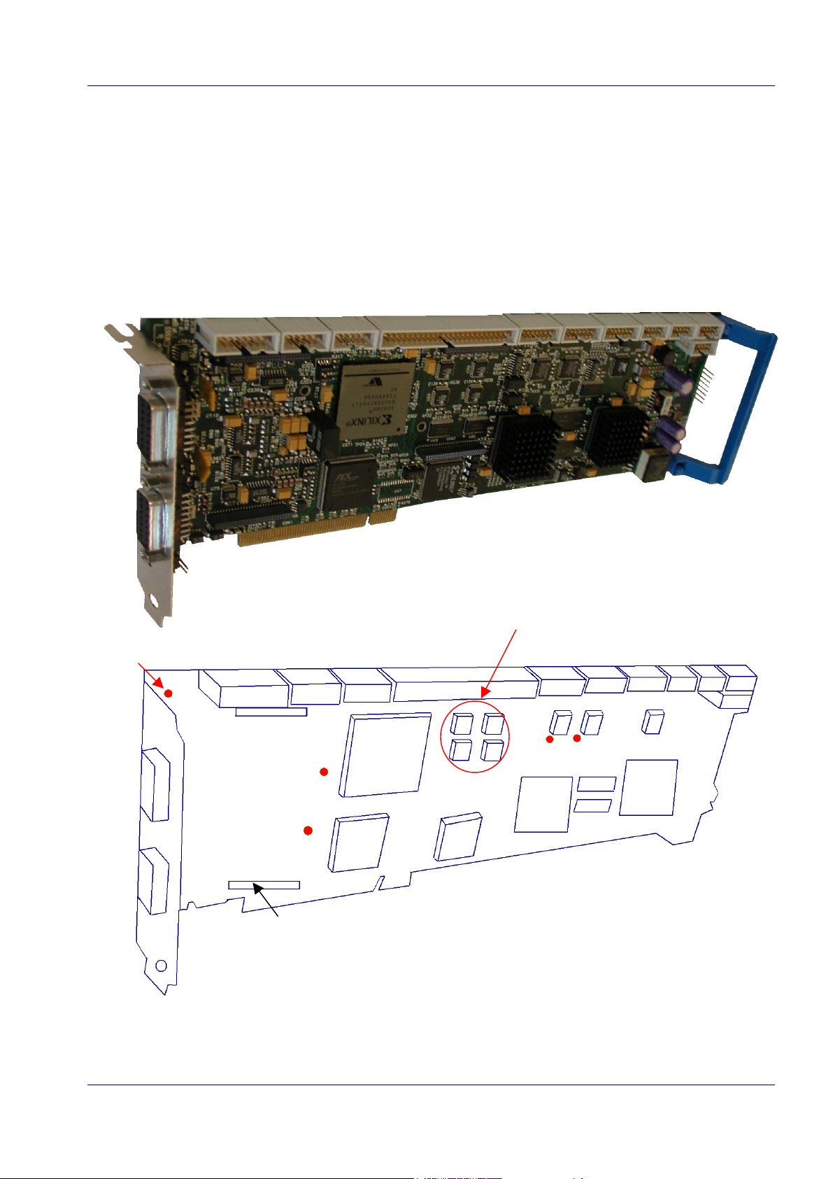
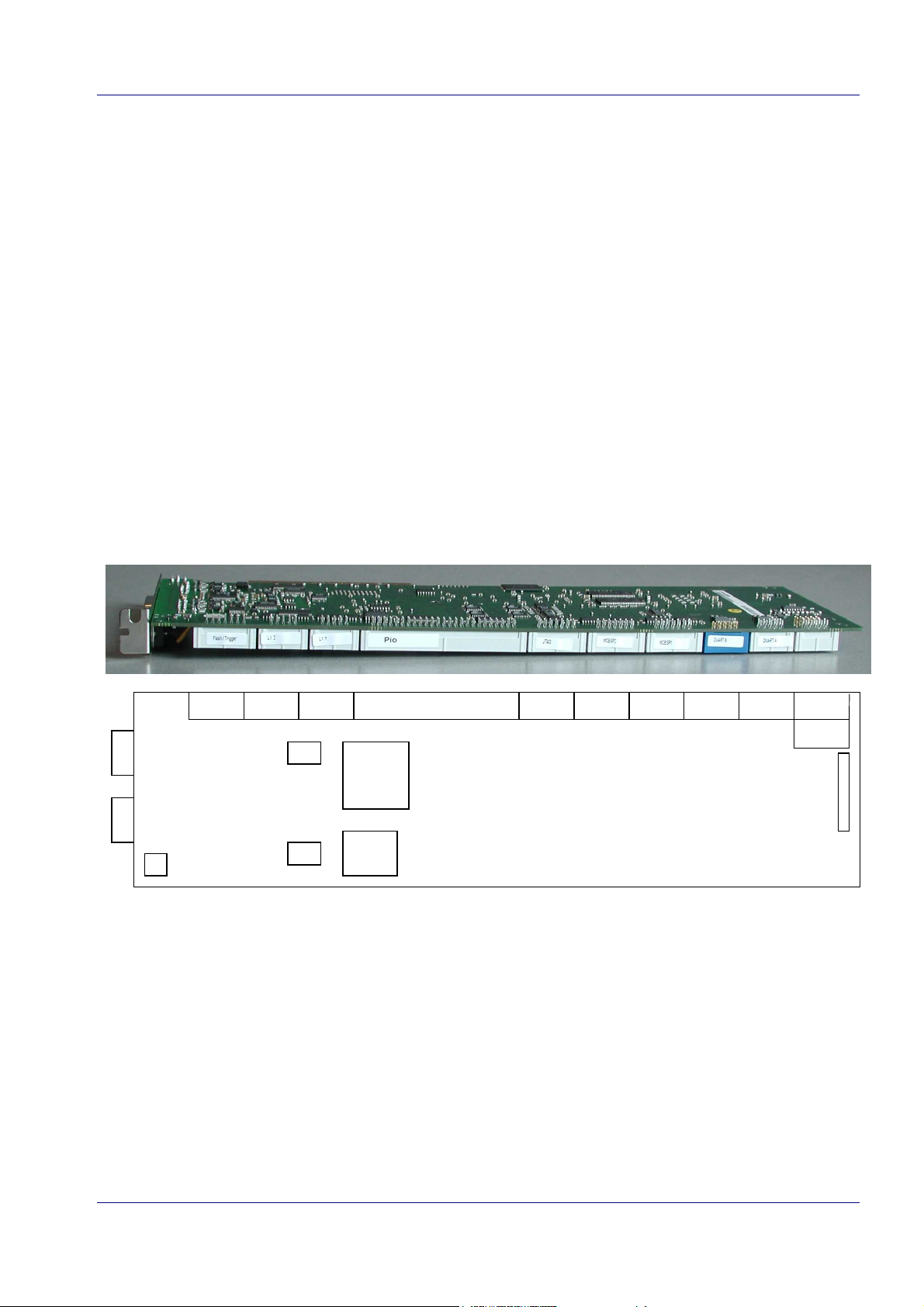
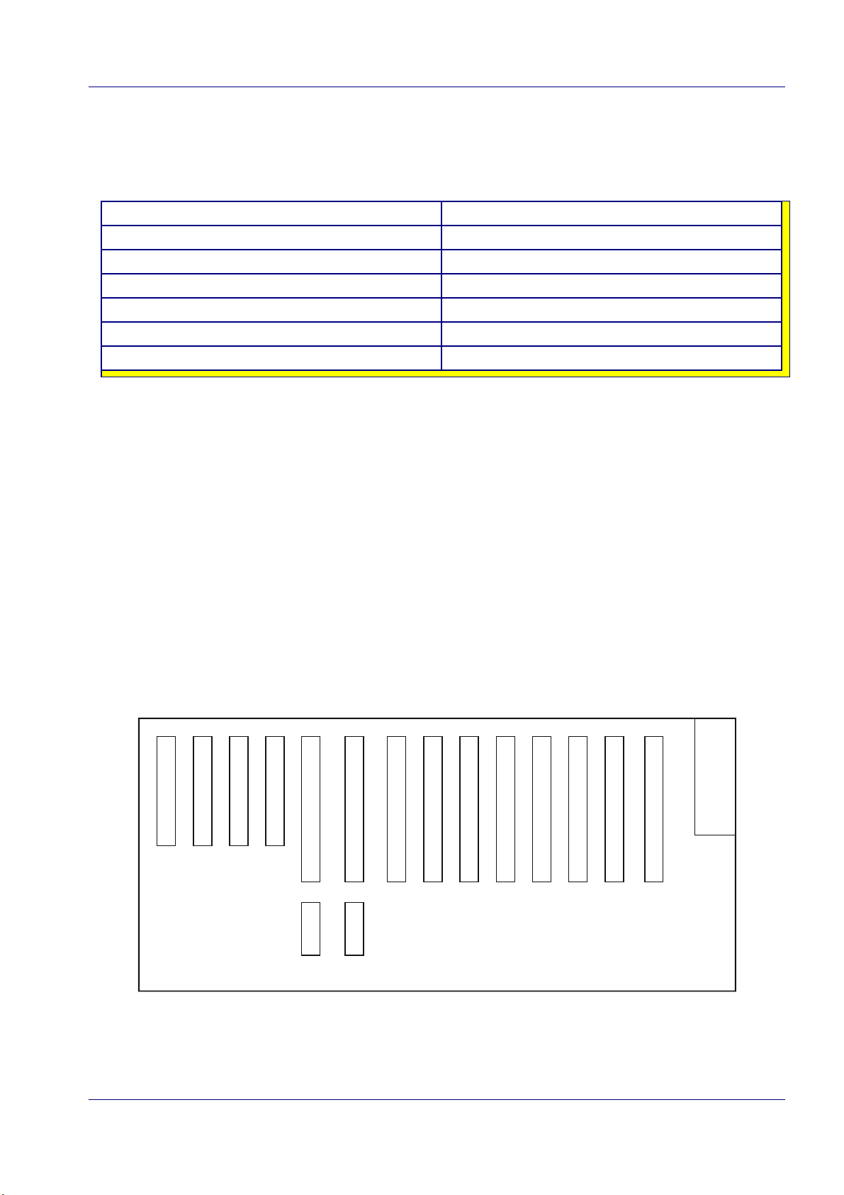
2.1.2 General Layout of the MVS6000 Family
This section shows the layout of the MVS6000 and the MVS6002 board.
Each board has different camera connectors, see page 2-12.
MVS6000
Hardware
Activity LED
connectors
for analog
cameras
input
FIFOs
flash/trigger LI2 LI1 PIO
connector for
camera module
input 1 LED
camera
CTRL
1
2 analog inputs
input 2 LED
PCI
CTRL
test
CTRL CTRL
DSP activity LEDs
32 MB
DSP
IO
CTRL
DSP
2
connector for
camera module
MVS6000 System Level Manual/1.0/Dec-2001 2-3
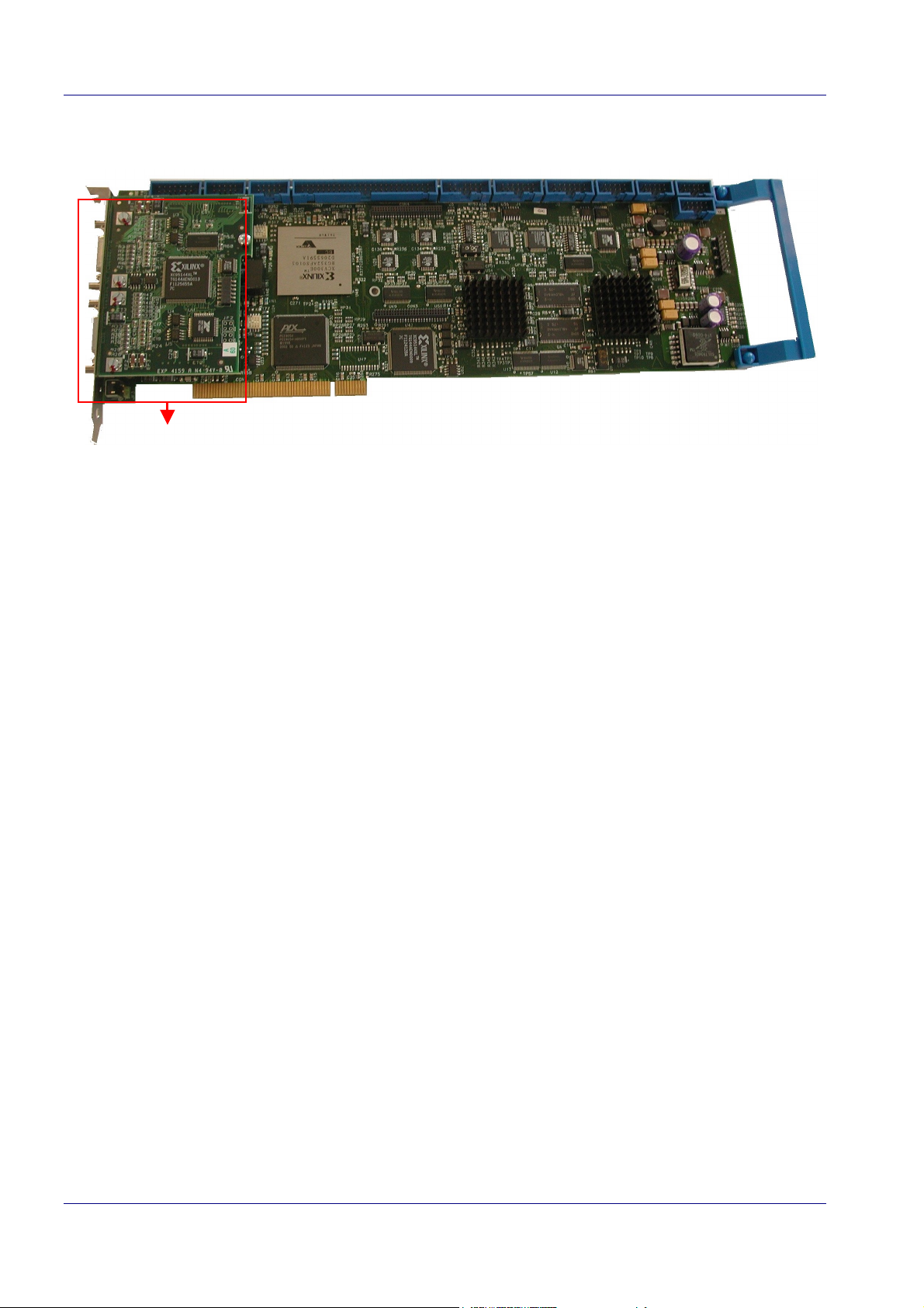
MVS6000
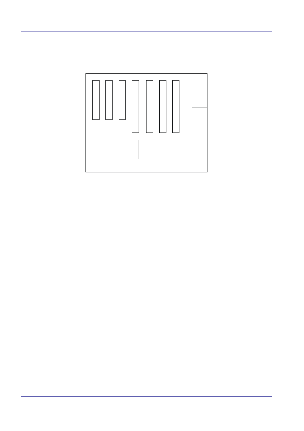
MVS6002
digital input
2.1.3 Power Consumption
The power consumption is lying within the PCI specifications:
· +5V: max. 4A
· +12V: 200mA + power of all connected cameras
· -12V: 150mA.
2.1.4 Minimum PC Requirements
· minimum Pentium III 600Mhz
· minimum 133Mhz front side bus
· minimum 64MB SDRAM
· video graphics card:
· minimum AGP*4
· resolution 1280*1024 with 64K colors should be supported
· 8 MB display memory: avoid using UMA (sharing SDRAM as display memory)
· for each board one full length PCI slot must be available.
2-4
MVS6000 System Level Manual/1.0/Dec-2001
Hardware
2.1.5 Communication
· PCI pipe communication
· RS232 communication:
The following baud rates are supported: 110, 300, 600, 1200, 2400, 4800, 9600, 14400,
19200, 38400, 57600, 115200.
Note:
ICOS provides the WinCommDll.dll for the communication (see page 5-2). This
1.
driver is available for WinNT4.0 and Win2000 (and can also be used for the ISA
and HS3L communication on MVS3xx and MVS100/200).
When no serial communication is used, the baud rate should be set to 0. This
2.
will improve the performance of the system.
2.1.6 Flat Cable Connectors
The connectors at the topside of the board are labeled:
C1 C2 C3 C4 C5 C6 C7 C8 C9 C10
SW2
xilinx
C11
JF4
JF3
SW1
plx
Each connector is explained in detail on the next page.
MVS6000 System Level Manual/1.0/Dec-2001 2-5
MVS6000
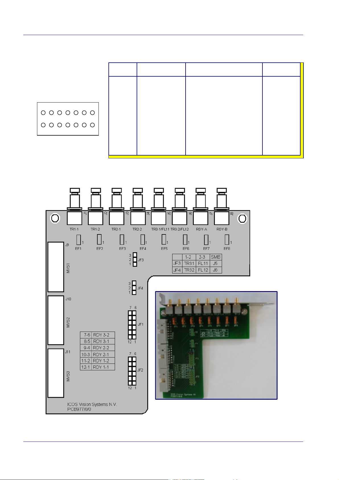
C1: flash trigger connector
Pin assignments:
1 2 3 4 5 6 7
8 9 10 11 12 13 14
Pin # Signal name Function Direction
8-14
1
2
3
4
5
6
7
GND
FLASH1
TRRDY1
TRIN1
FLASH2
TRRDY2
TRIN2
NC
Ground
Flash channel 1
Trigger ready channel 1
Trigger input channel 1
Flash channel 2
Trigger ready channel 2
Trigger input channel 2
Not Connected
-
output
output
input
output
output
input
-
Note: A Flash trigger board, using SMB snap-on connectors, is available for easy connection.
2-6
MVS6000 System Level Manual/1.0/Dec-2001
Hardware
C2 & C3: LI1 and LI2
These connectors are serial connections to the ICOS light interface (LI) boards.
C4: PIO
This connector supports four groups of 8 bit PIO that can be programmed as an input or output.
The MVS software does not yet support this.
C5: JTag
This connector is used for in circuit emulation, programming primary software for testing in
production environment or for boundary scan to check the processors.
C6 & C7: MCBSp2 and MCBSp1
This is a multi-channel buffered serial port: it is a standard serial port for connecting multiple
TMS320C6202 DSP processors. The MVS software does not yet support this port.
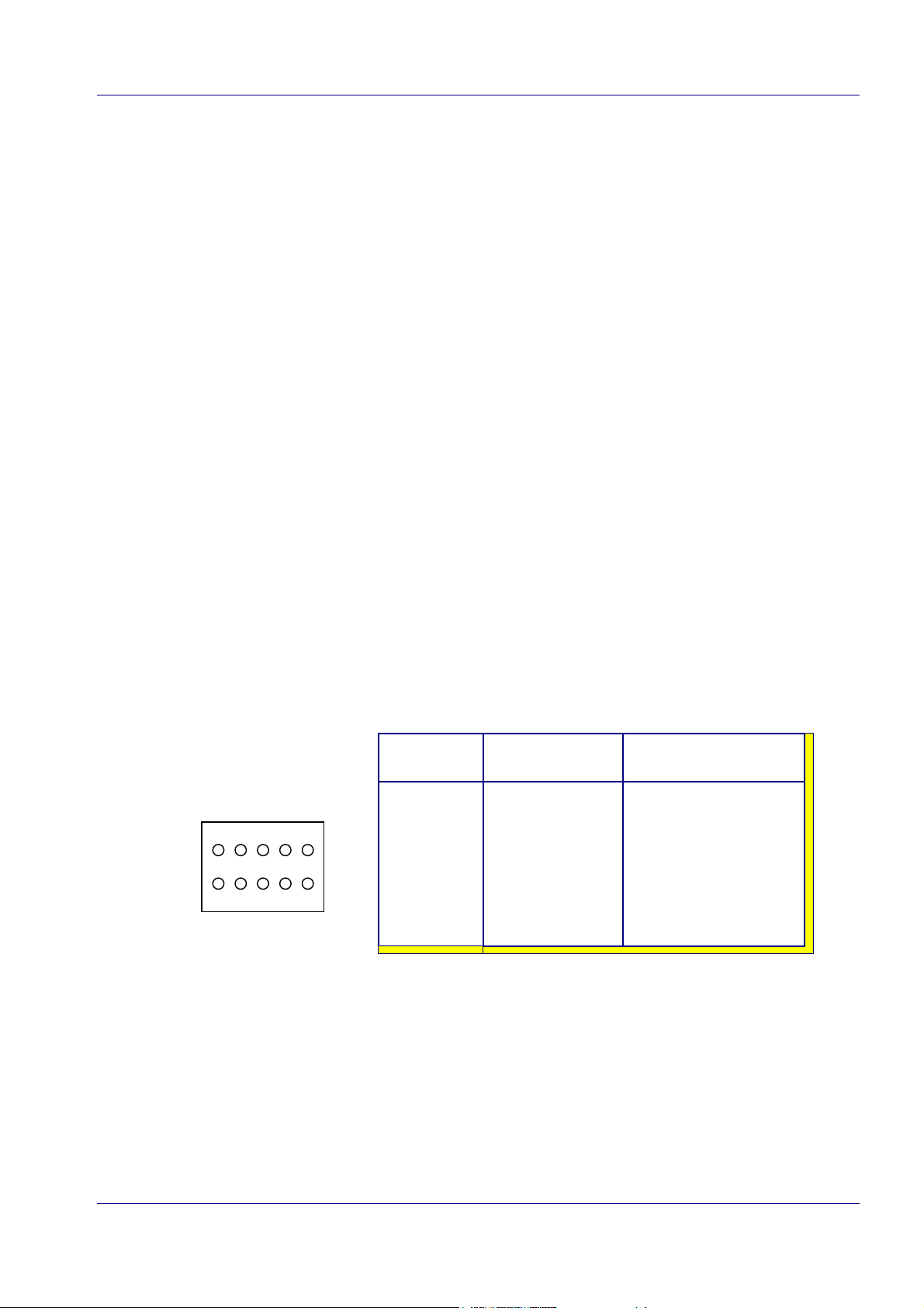
C8 & C9: Duart B and Duart A
These ports are used for serial communication with the board and can be set in menu mode,
message mode or host mode.
Pin assignments:
1 2 3 4 5
8 9 10 7 6
Pin # Signal name Function
2
3
5
8
9
1,4,6,7,10
RXD
TXD
GND
CTS
RTS
NC
Receive data
Transmit data
Ground
Clear to send
Request to send
Not connected
C10: Can Bus
This is not supported.
C11:
Connector used for diagnostics purposes in production (at ICOS).
MVS6000 System Level Manual/1.0/Dec-2001 2-7
2-8
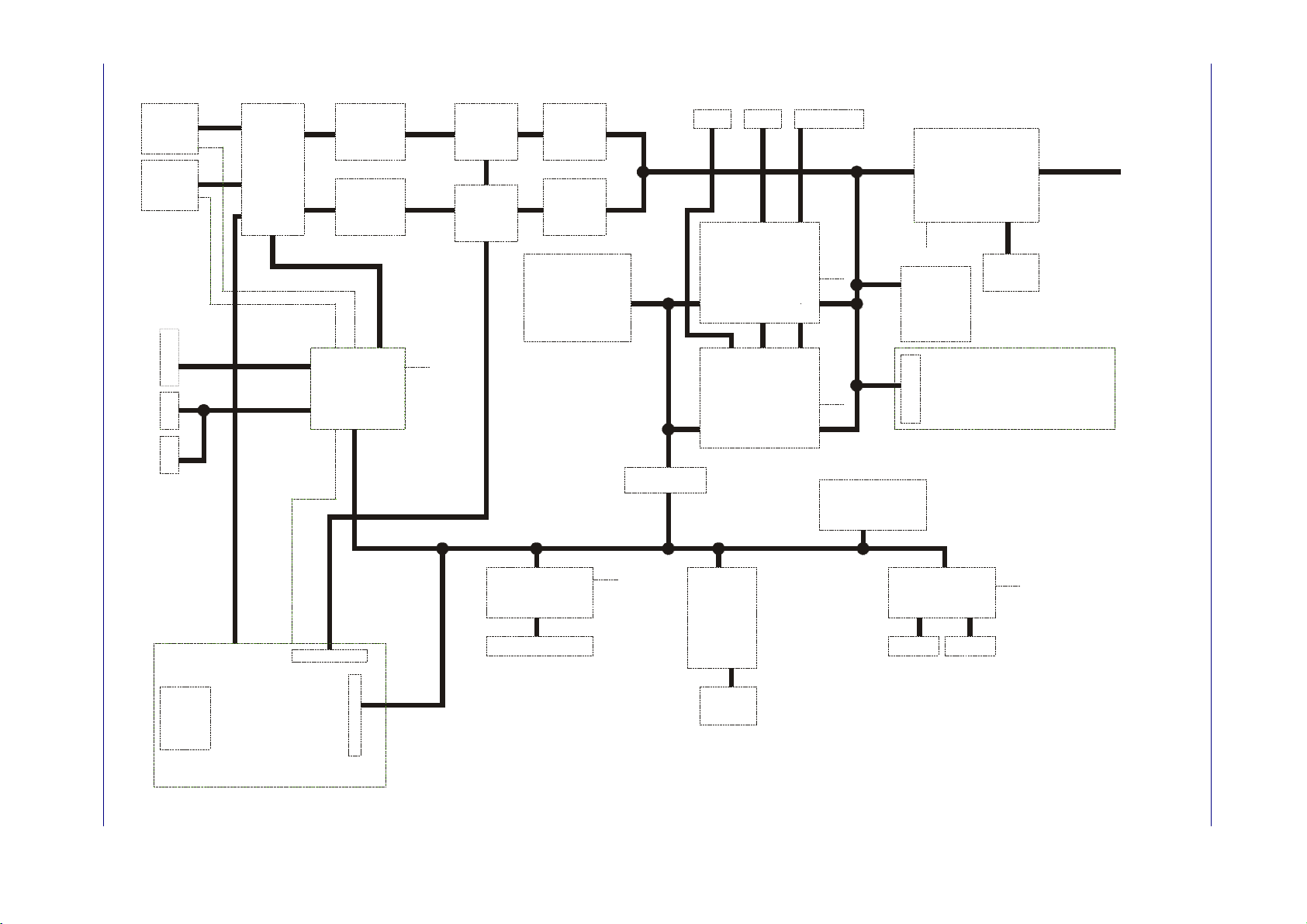
2.1.7 Block Diagram MVS600x
MVS6000
1 x HR
1 x Med Res
or
2 x Med Res
CON 1
1 x HR
1 x Med Res
or
2 x Med Res
CON 2
ANALOG
CROSSBAR
Flash/Trigger
Serial
Light Interfa ce
MVS6000 System Level Manual/1.0/Dec-2001
Camera module
( Second slot )
A/D conv.
10 bit
40 MHz
A/D conv.
10 bit
40 MHz
Camera
CTRL
32
Digital output
INT
10
10
Mux
Input LUT
Mux
Input LUT
32
PIO : 32 I/O
SyncFIFO
4x4Kx9
SyncFIFO
4x4Kx9
32 MByte
SDRAM
(2 banks)
(125 MHz)
8
32
INT
32
32
32
TRANSX
McBSP1 McBSP2
McBSP
DSP
TMS320C6202
250 MHz
McBSP
McBS P
McBSP
DSP
TMS320C6202
250 MHz
I/O - INT
CTRL
JTAG emulator
JTAG
XBIEMI
JTAG
XBIEMI
32 32
INT
32
32
INT
32
BOOT FEPROM
512 KByte
16
DUART
SC28L92A1B
TQFP44
RS-232 RS-232
PCI master I.F.
PLX905 4
INT
SEEPROM
Transfer
1kByte
CTRL
Expansion bus module
( IEEE-1394, F lash EPROM, ... )
8
INT
PCI_V2.2
33 MHz
Camera
Con
16
SEEPROM
1kByte
Hardware
de
2.2 Racks
Two types of racks are planned: standard and small.
standard rack (16 slots) small rack (7 slots)
4 PCI slots (Þ max 4 MVS) 3 PCI slots (Þ max 3 MVS)
2 PICMG slots (for a PC board) 1 PICMG slot
8 ISA slots (for LIs, PIO, Atos, power) 3 ISA slots
Pentium III 600E Pentium III 600E
128 MB memory 128 MB memory
H: 178 mm - W: 448/483 mm - D: 460 mm H: 177 mm - W: 268/318 mm - D: 425 mm
The PC board is a Microbus MAT915 with Ethernet and SVGA on board.
A 17-inch monitor is advised. Only one monitor is used, as well on the CI as for SL products.
The rack dimensions are the same as the MVS3x0-racks, but the position of the mounting holes is
different on the small rack.
The back plane is different from that of the MVS3x0-racks.
The distinction between the different MVS6000s is based on their positions in the rack (slot 1, slot
2, ... see below). They have no address anymore (any more jumpers).
Configuration of the Standard Rack
4 PCI slots 8 ISA slots
)
)
3
t
o
l
s
(
0
0
0
6
S
V
M
)
2
t
o
l
s
(
0
0
0
6
S
V
M
4
t
o
l
s
(
0
0
0
6
S
V
M
2 PICMG slots
)
1
t
o
l
s
(
0
0
0
6
S
V
M
S
O
T
A
r
e
e
c
c
a
a
f
f
r
r
e
e
t
t
n
n
i
i
t
t
h
h
g
g
i
i
l
l
O
I
P
t
e
k
c
a
r
b
r
e
w
o
p
e
w
o
p
CPU
front si
MVS6000 System Level Manual/1.0/Dec-2001 2-9
MVS6000
de
G
Configuration of the Small Rack
3 PCI slots 3 ISA slots
MVS6000 (slot 3)
1 PICM
slot
MVS6000 (slot 1)
MVS6000 (slot 2)
CPU
power
PIO
light interface
front si
Tip: Slot 1 is always the closest to the PC board.
2-10
MVS6000 System Level Manual/1.0/Dec-2001
Hardware
2.3 Camera Connections and Cables
Camera timing kits are programmable on the board. For each board two different timing kits can
be programmed.
Up to four standard resolution (SR) cameras or two high resolution (HR) cameras (ADIMEC), can
be connected to the MVS6000 board.
A combination of two SR cameras with one HR camera is also possible. In this configuration, the
same types of SR cameras must be connected to connector 1 and the HR camera must be
connected to connector 2.
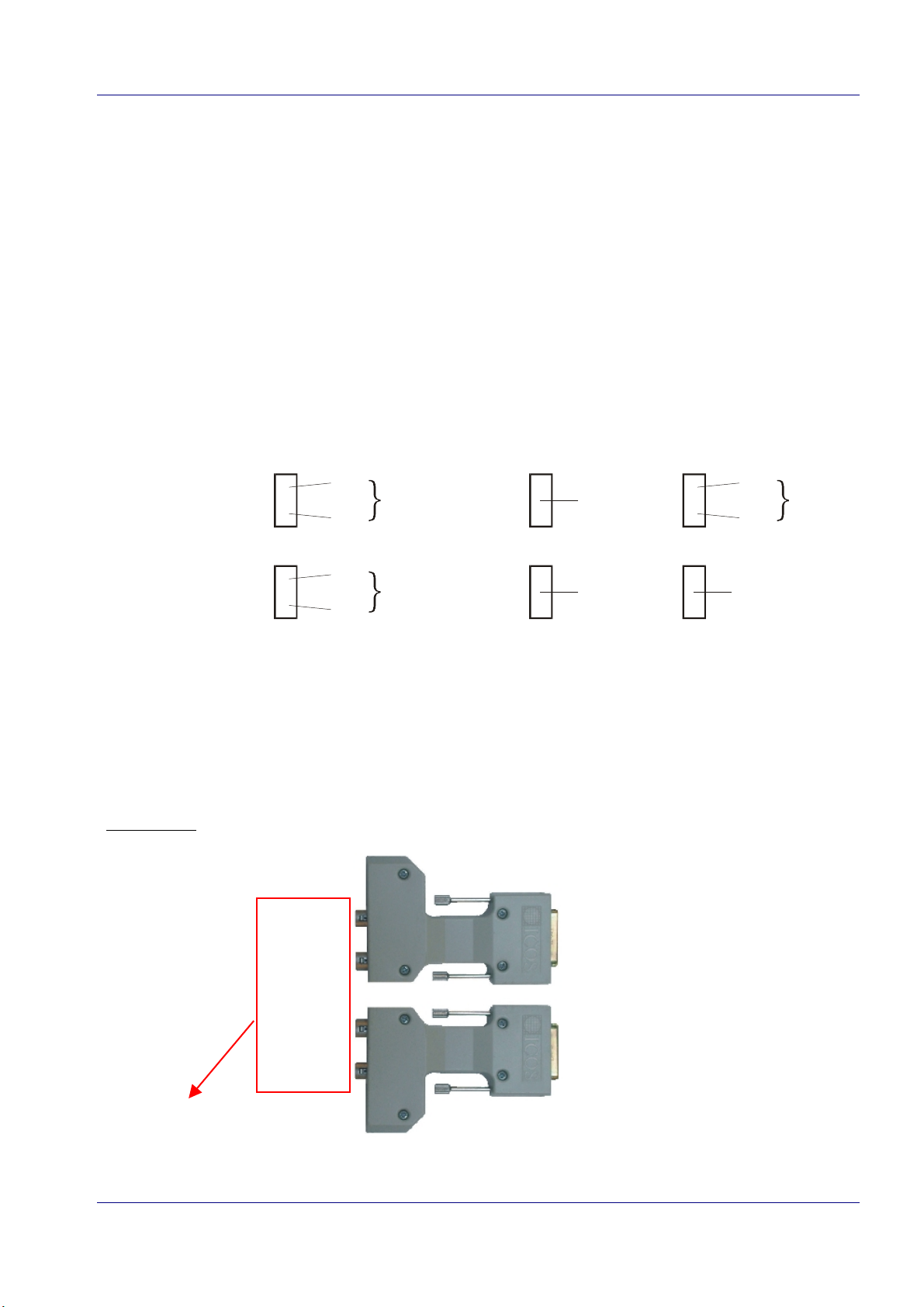
Following figure summarizes the allowed combinations for the MVS6000 board:
Connector 1
Connector 2
Note: Cameras may be missing in these configurations.
To connect:
· two SR cameras to one of the MVS connectors of the MVS600 board, a breakout box must be
used.
· four SR cameras to a MVS6000 board, two symmetrical breakout boxes must be used.
An example of two symmetrical breakout boxes (see also page 2-13).
camera 1
camera 2
SR
SR
SR
SR
same
type
same
type
HR
HR
to connector 1
of MVS6000
SR
SR
HR
same
type
camera 3
camera 4
camera numbering on
MVS6000 board (see
also page 3-23).
MVS6000 System Level Manual/1.0/Dec-2001 2-11
to connector 2
of MVS6000

MVS6000
2.3.1 Connectors and Cables
2.3.1.1 Connectors
· MVS6000: the bracket has two connectors, each for either two standard resolution cameras or
one high resolution camera.
· MVS6001: the bracket has two connectors, one for the IVC-1000 camera and one for either
two standard resolution cameras or one high resolution camera.
· MVS6002: the bracket has two connectors for the IVC-1000 camera.
connector 1
connector
connector 2
paper clip reset
MVS6000
15 pin connector of the MVS6000:
1
9
2
10
3
11
4
12
5
13
6
14
7
8
15
IVC-1000
MVS6001
(mounted in a rack)
Pin # Signal
1
2
3
4
5
6
7
8
9
10
11
12
13
14
15
Video Cam 1
HD Cam 1
VD TTL cam 1
Video 2 GND
GND
Clock signal ADIMEC MX12P +
HD Cam 2
12 V DC .75 A max out
Video Cam 1 GND
GND
Video Cam 2
Shutter Control Cam 1
Shutter Control Cam 2
Clock signal ADIMEC MX12P -
VD TTL cam 2
for
MVS6002
2-12
MVS6000 System Level Manual/1.0/Dec-2001
Hardware
2.3.1.2 Breakout Boxes and Cables
Breakout Boxes
To connect two or more SR cameras to an MVS board, a breakout box must be used. A breakout
box has a SubD15 connector In and two or three Hirose connectors Out.
For the Hirose connector of the STxx Sony cameras and the Teli camera, a new connector
standard (EIAJ standard) has been introduced in which Pin 11 is no longer used as 12V input but
as trigger input. See the following table for more details.
Hirose connector Pin Nr Old Pin Layout New EIAJ standard
1GNDGND
2 + 12 V DC + 12 V DC
3 Video Out (GND) Video Out (GND)
4 Video Out (signal) Video Out (signal)
5 HD in (GND) HD in (GND)
6 HD in (Signal) HD in (Signal)
7 VD in (Signal) VD in (Signal)
8 TRIG in (GND) GND
9 Trig In (Signal) /
10 GND WEN output (Signal)
11 + 12 V DC Trig In (Signal)
12 VD in (GND) VD in (GND)
Warning: New cables must be used for the connector with the new EIAJ standard.
The problem is that the connectors are physically “compatible”, but if you use old
cables with the new connectors or the new cables with the old connectors, either the
camera or the MVS board will be seriously damaged.
To avoid confusion:
· The cameras with the new EIAJ standard connector will get a blue label.
· The breakout boxes compatible with the old camera connectors are gray.
The breakout boxes with the new EIAJ standard Hirose connectors have a blue
label or a blue housing.
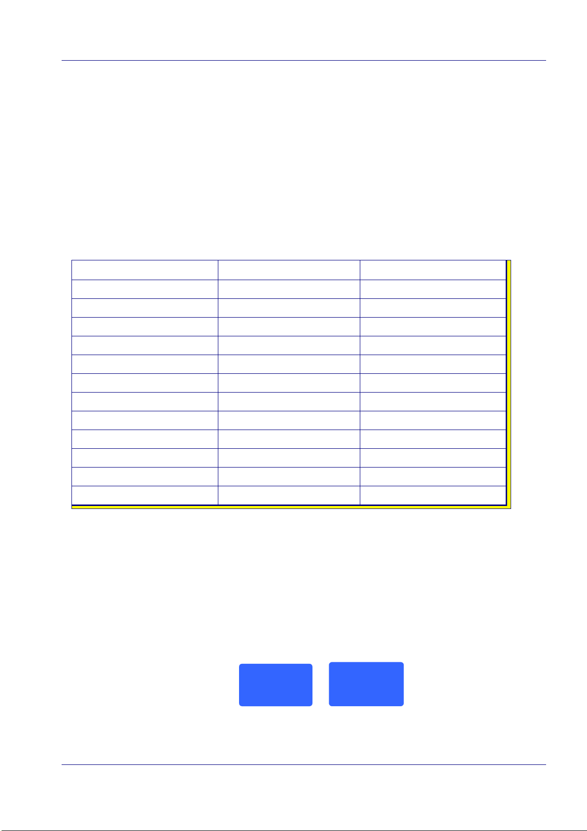
An example of a blue label for a breakout box:
ICOS Vision Systems
MVS 966R
REV : 0/0/0
New EIAJ Standard
Product of BELGIUM
ICOS Vision Systems
MVS 966L
REV : 0/0/0
New EIAJ Standard
Product of BELGIUM
· The cables will get a blue label.
MVS6000 System Level Manual/1.0/Dec-2001 2-13
MVS6000
An overview of the available breakout boxes:
MVS number connector In connectors out Connectors out: pin layout color
MVS962 SubD15 3 x Hirose Old pin layout gray
MVS963 SubD15 2 x Hirose old pin layout gray
MVS964 SubD15 2 x Hirose new EIAJ pin layout blue
MVS966 SubD15 3 x Hirose new EIAJ pin layout blue
Cables
there are three types of cables to connect the camera with the MVS6000 board:
· SR cables to connect with the standard Hirose connector
· SR cables to connect with the new EIAJ standard Hirose connector (blue label)
· HR cables
Note: For the SR cameras, the same cables are used as for connecting to the MVS3x0.
For the HR cameras (ADIMEC), other cables are used than for connecting to the MVS3x0.
The next two tables give an overview of the cables that must be used with and without a video
splitter.
Note: A video splitter transmits the output of the two cameras to the two “twin” MVS boards.
Camera connections without video splitter:
camera type
connection
camera to
MVS3x0
camera to
MVS6000
HR camera
SL:
CW4448 (2m)
CW4449 (5m)
CW4450 (10m)
CW4332 (3m)
CI:
SL:
CW4703 (2m)
CW4704 (5m)
CW4705 (10m)
CI:
CW4642 (3m)
SR camera
old standard
SL:
CW4473 (2m)
CW4474 (5m)
CW4475 (10m)
CI:
CW4603 (5.5m)
CW4711 (2m)
SR camera
EIAJ standard
blue label
CW4712 (5m)
CW4713 (10m)
camera to
breakout box
2-14
- - -
CW4430 (2m)
CW4431 (5m)
CW4432 (10m)
MVS6000 System Level Manual/1.0/Dec-2001
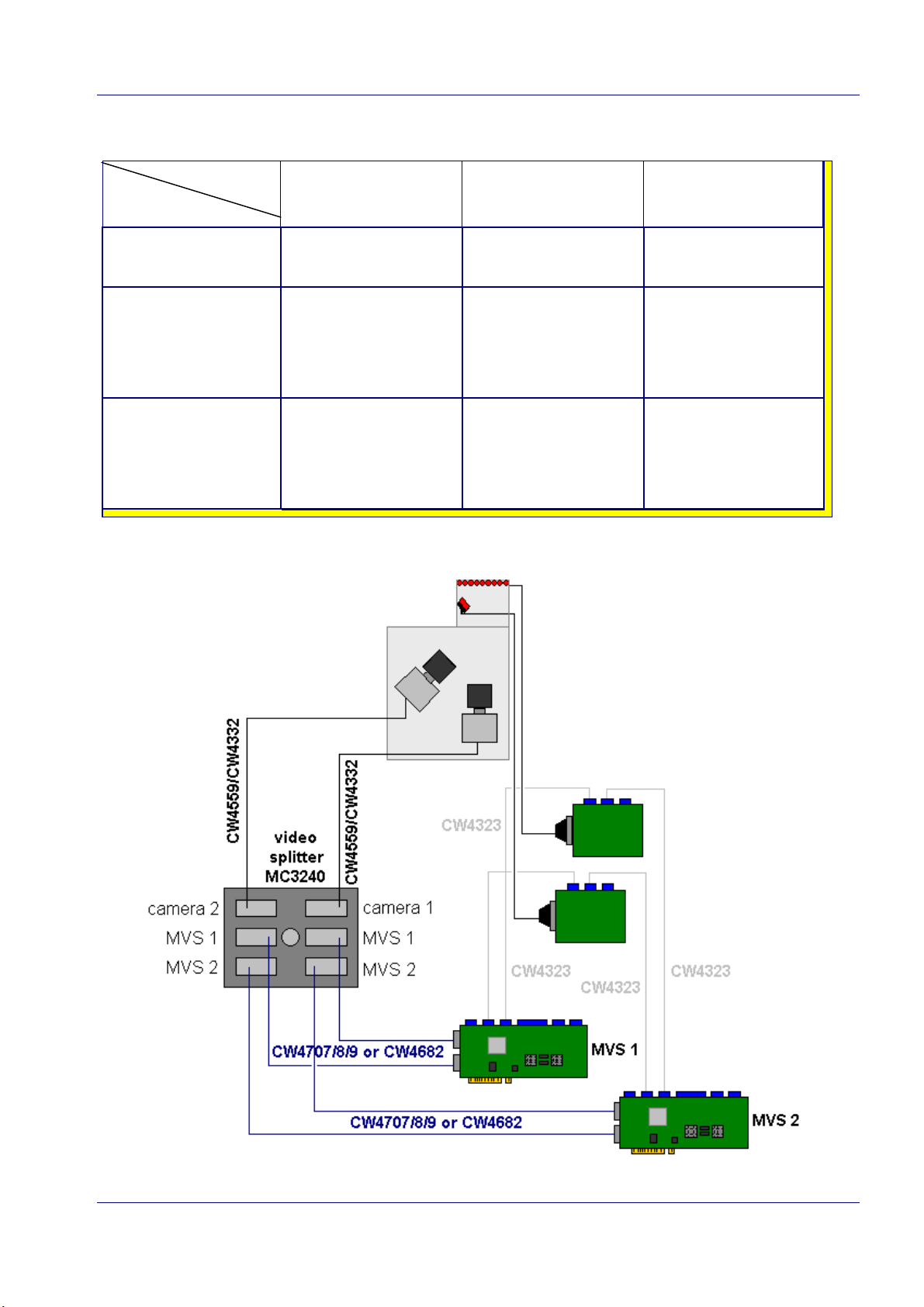
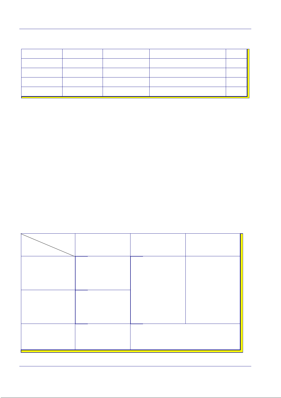
Camera connections with video splitter:
Hardware
camera type
connection
camera to
video splitter
video splitter to
MVS3x0
video splitter to
MVS6000
When using the acceleration kit on a 3D STEREO system, the connections are as follows:
SL:
CI:
SL:
CI::
SL:
CI:
HR camera SR camera
old standard
CW4559 (0.3m)
CW4332 (3m)
CW4560 (2m)
CW4595 (5m)
CW4596 (10m)
CW4616 (3m)
CW4707 (2m)
CW4682 (5m)
CW4709 (10m)
CW4708 (3m)
- - - - - -
- - - - - -
- - - - - -
SR camera
EIAJ standard
blue label
MVS6000 System Level Manual/1.0/Dec-2001 2-15

MVS6000
2.3.2 Supported Cameras
With MVS Software 24.0.0:
Only analog cameras are supported with MVS software 24.0.0:
Sony
XC75CE_2
XC75CE_6
XC75CE_7
ST50CE_6
· interlaced
· no restart reset
· frame integration
· resolution 752X574
· ID is 1
· interlaced
· restart reset
· frame integration
· resolution 752X574
· ID is 2
· interlaced
· restart reset
· field integration
· resolution 752X574
· ID is 3
· interlaced
· restart reset
ST50CE_7
ST30CE_6
· frame integration
· resolution 752X574
· ID is 23
· interlaced
· restart reset
· field integration
· resolution 752X574
· ID is 24
· interlaced
· restart reset
· frame integration
· resolution 752X574
· ID is 30
2-16
MVS6000 System Level Manual/1.0/Dec-2001

Hardware
ST30CE_7
ST70CE_6
ST70CE_7
XC55E_5
· Interlaced
· restart reset
· field integration
· resolution 752X574
· ID is 31
· interlaced
· restart reset
· frame integration
· resolution 752X574
· ID is 27
· interlaced
· restart reset
· field integration
· resolution 752X574
· ID is 28
· progressive scan,
· restart reset
Teli
ADIMEC
XC8500M_5
CS8531_5
40M50PC
· field integration
· resolution640X492
· ID is 21
· progressive scan,
· restart reset
· field integration
· resolution 752X576
· ID is 14
· progressive scan,
· restart reset
· field integration
· resolution 640X492
· ID is 25
· progressive scan,
· restart reset
· field integration
· resolution 10240X1024
· ID is 2
MVS6000 System Level Manual/1.0/Dec-2001 2-17
 Loading...