

ICOP VSX-6127 User Manual
VSX-6127
DM&P Vortex86SX 300MHz
3.5” CPU Module
with 8S/3USB/VGA/LVDS/LAN/GP IO/CF
128MB DDR2 Onboard
User’s Manual
(Revision 1.2A)
Copyright
The information in this manua l is subject to cha nge without notice for continuous improvement in
the product. All rights are reserved. The manufacturer assumes no responsibility for any
inaccuracies that may be contained in this document. And makes no commitment to update or to
keep current the information contained in this manual.
No part of this manual may be reproduced, copied, translated or transmitted, in whole or in part ,
in any form or by any means without the prior written permission of the ICOP Technology Inc..
Copyright 2007 ICOP Technology Inc.
Manual No. IUM6127000-01 Ver.1.0A
September, 2007
Manual No. IUM6127000-01 Ver.1.1A
December , 2007
Manual No. IUM6127000-01 Ver.1.2A
July, 20 08
Trademarks Acknowledgment
Vortex86SX is the registered trademark of ICOP Technology Inc.
Other brand names or product names appearing in this document are the properties
and registered trademarks of their respective owners. All names mentioned herewith
are served for identification purpose only.

T a b l e o f C o n t e n t s
T a b l e o f C o n t e n t s.............................................................iii
C h a p t e r 1 Introduction……………………………………………1
1.1 Packing List............................................................1
1.2 Product Description................................................1
1.3 Specifications.........................................................3
1.4 Board Dimension....................................................5
C h a p t e r 2 Installation……………………………………………..6
2.1 Board Outline.........................................................6
2.2 Connectors & Jumpers Location............................7
2.3 Connectors & Jumpers Summary...........................9
2.4 Pin Assignments & Jumper Settings......................11
2.5 System Mapping...................................................25
2.6 Watchdog Timer.....................................................27
2.7 GPIO......................................................................28
2.8 SPI Flash...............................................................29
C h a p t e r 3 Driver Installation……………………………………30
Appendix ………………………………………………………………..31
A. TFT Flat Panel Data Output ......................................31
B. TFT Flat Panel Support List.......................................32
C. LVDS Flat Panel Support List....................................33
D. Flat Panel Hardware Setting.....................................34
E. Flat Panel Wiring and Lighting..................................35
F. TCP/IP library for DOS real mode..............................36
G. BIOS Default Setting.................................................37
Warranty............................................................................................38
Vortex86SX-6127 Vortex86SX 3.5” CPU Module
1
C h a p t e r 1
Introduction
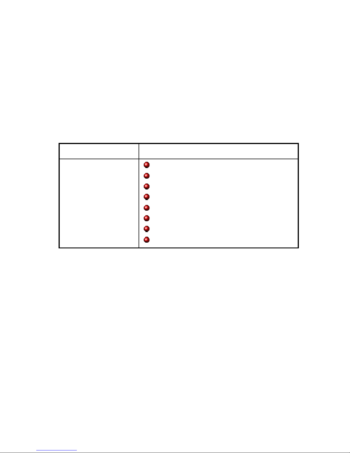
1.1 Packing List
Product Name Package
VSX-6127
Embedded Vortex86SX CPU All-in-One Board
Manual & Drivers CD x 1
RS232 cable x 7
PRINTER cable x1
IDE cable x 1
USB cable x 1 (USB port x 2)
GPIO cable x 2
YKB for Keyboard & PS/2 Mouse x 1

Vortex86SX-6127 Vortex86SX 3.5” CPU Module
2
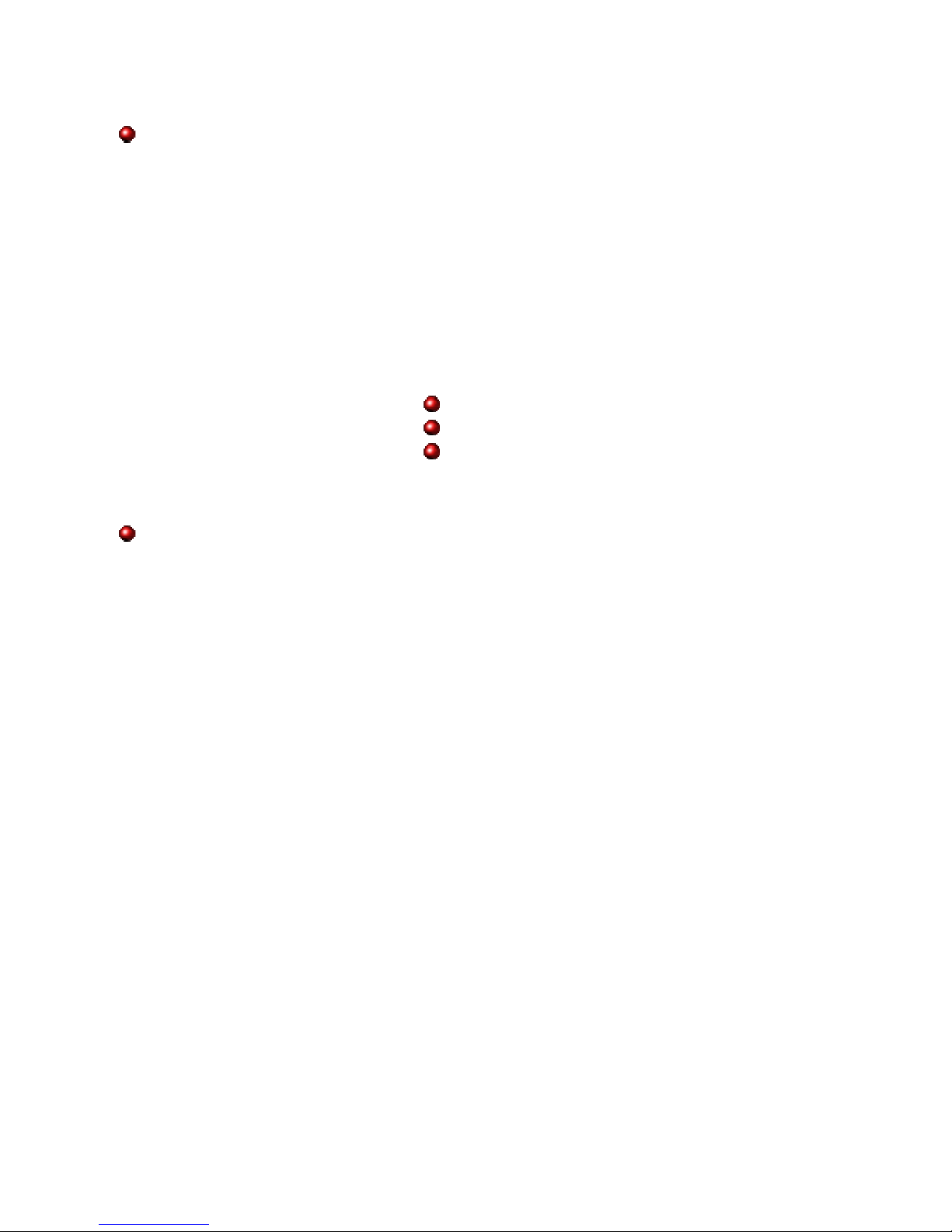
1.2 Product Description
The VSX-6127 family of low-power x86 embedded controller is designed to meet 3.5”
specification, and integrated with the following features.
300 MHz Vortex86SX System-On-Chip
VGA, TFT/LVDS LCD support up to
1280x1024 resolution
128MB DDR2 system memory
Enhanced IDE (UltraDMA-100/66/33)
10/100Mbps Ethernet
3 USB 2.0 (host)
Up to 8 serial ports
Parallel port
16-bit GPIO x2
PC/104 expansion bus
Onboard 2MB SPI Flash
PC/104-Plus expansion bus
Meet PC/104 stacking spec.
2 watchdog timer
3 PWM channels
JTAG interface
AMI BIOS
Mini-PCI (TypeⅢ)
Single voltage +5V DC
Support extended operating
temperature range of -20°C to +70°C
The VSX-6127 3.5” family of embedded controller is designed with backward compatibility in
mind, to provide migration path for projects facing end-of-life challenges with their existing x86
based 3.5” controller. The VSX-6127 family of controller is designed as a plug in replacement,
with backward compatibility to support legacy software to help extend existing product life cycle
without heavy re-engineering.
VSX-6127 is suitable for broad range of data-acquisition, Industrial automation, Process control,
Automotive controller, AVL, Intelligent Vehicle management devic,Medical device, Human
machine interface, Robotics, machinery control And more…application that required small
footprint, low-power and low-cost hardware with open industry standard such as 3.5 ”.
Vortex86SX-6127 Vortex86SX 3.5” CPU Module
3
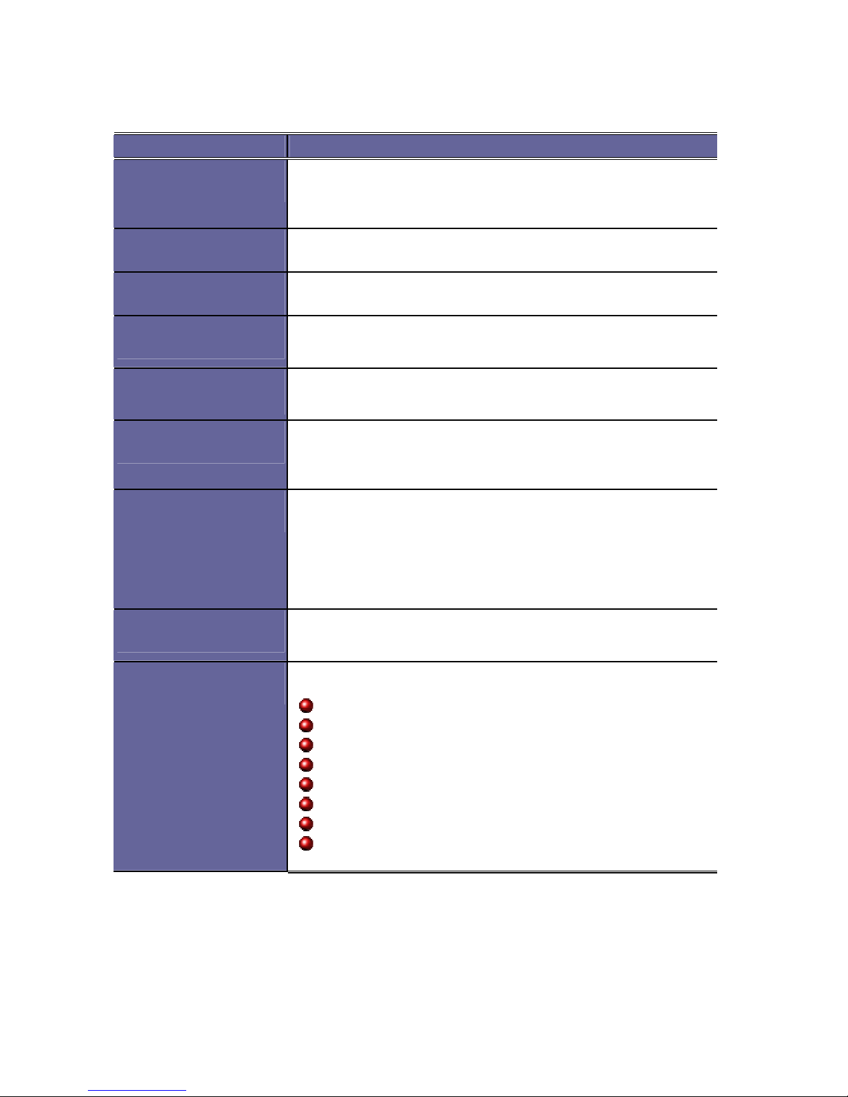
1.3 Specifications
Features VSX-6127
CPU
DM&P SoC CPU Vortex86SX- 300MHz
Real Time Clock with Lithium Battery Backup
Cache
L1:16K I-Cache, 16K D- Cache
BIOS
AMI BIOS
Bus Interface
PC/104 & PC/104+ Standard Com pliant
System Memory
128MB DDR2 onboard
Watchdog Timer
Software programmable fr om 30.5 us to 512 seconds x2
sets(Watchdog 1 fully compatible with M6117D)
VGA
XGI Volari Z9s Chipset
VGA and TFT Flat Panel Interface Support
LVDS Flat Panel Interface Support
Onboard 32MB VGA Memory
Support resolution up to 1280 x 1024,16MB color s
LAN
Integrated 10/100M Et hernet
I /O Interface
Enhanced IDE port (UltraDMA -100/66/33) x1
FDD port x1
RS-232 port x7
RS-232/485 port x1 (RS485: Auto Dir ection)
Parallel port x1
USB port x3 (USB 2.0 version)
16-bit GPIO port x2
10/100Mbps Ethernet port x1
Vortex86SX-6127 Vortex86SX 3.5” CPU Module
4
Connectors
2.00 mm 44-pin box header for IDE x1
2.00 mm 44-pin box header for LCD x 1
2.00 mm 34-pin box header for FDD x1
2.00 mm 26-pin box header for Printer x1
2.00 mm 20-pin box header for 16-bit GPIO x2
2.00 mm 16-pin header for LVDS x 1
2.00 mm 10-pin box header for RS-232 x7
2.00 mm 10-pin box header for USB x1
2.54 mm 4-pin header for DC-in x1
2.54 mm 3-pin header for RS-485 x1
2.54 mm 2-pin header for Reset x1
1.25 mm 6-pin Wafer for JTAG x1
0.8mm 124-pin MiNi PCI connector x1
External 15-pin D-Sub female connector for VGA x1
External 9-pin D-Sub male connector for RS-232 x1
Ext ernal RJ-45 connector for Ethern et x1
External USB connector for x1
External Mini DIN soc ket for Keyboard/Mo use x1
Type I/II Compact Flash slot x1
Flash Disk Support
On board 2MB SPI Flash Disk (Driver: A)
44-pin IDE Flash Disk( EmbedDisk 16MB or above)
Type I/II CF Card
Power Requirement
Single Voltage +5V @620mA
Dimension
102 X 144mm (4.01 x 5.67 inches)
Weight
148g
Operating
Temperature
-20oC ~ +70oC
-40°C ~ +85°C (Optional)

Vortex86SX-6127 Vortex86SX 3.5” CPU Module
5
1.4 Board Dimension
Vortex86SX-6127 Vortex86SX 3.5” CPU Module
6
C h a p t e r 2
Installation
2.1 Board Outline
Vortex86SX-6127 Vortex86SX 3.5” CPU Module
7
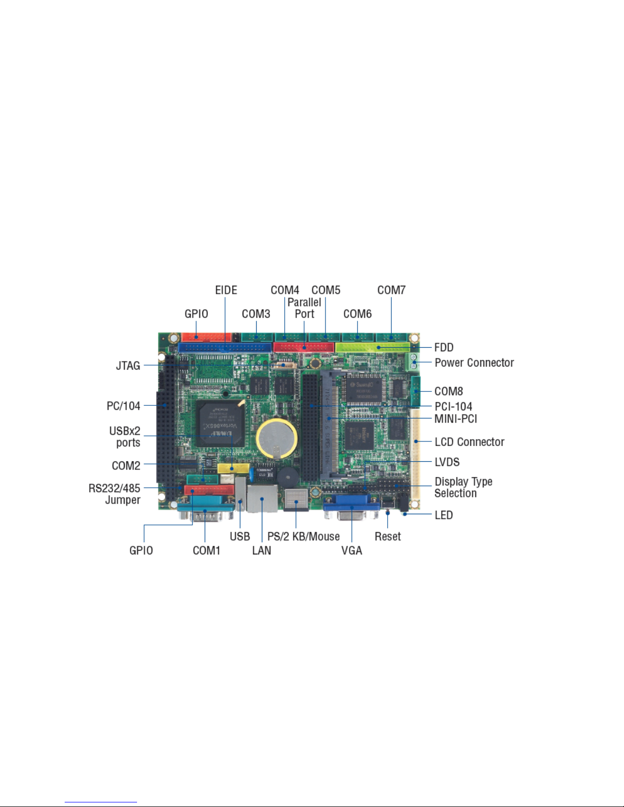
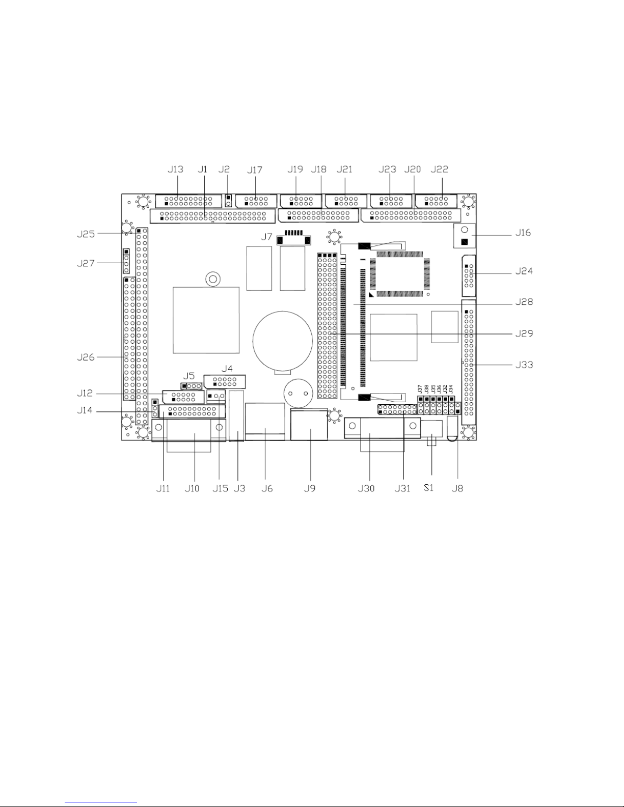
2.2 Connectors & Jumpers Location
Connectors
Vortex86SX-6127 Vortex86SX 3.5” CPU Module
8
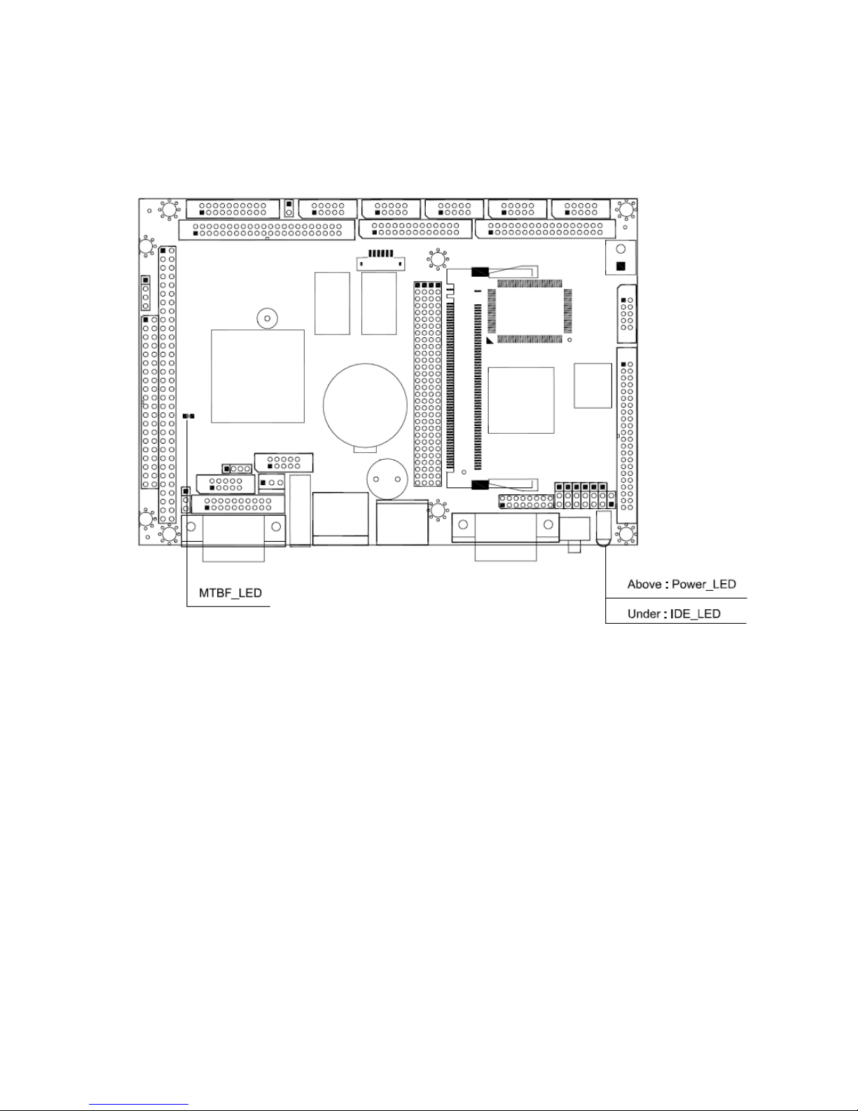
Jumpers & LEDs
Vortex86SX-6127 Vortex86SX 3.5” CPU Module
9
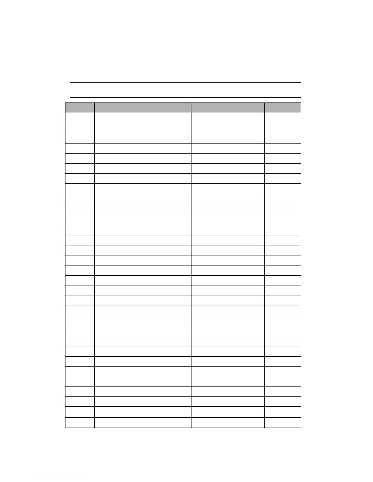
2.3 Connectors & Jumpers Summary
Summary Table
Nbr Description Type of Connections Pin nbrs.
J1 IDE Box Header, 2.0 ,22x2 44-pin
J2 CF Card Master/Slave Select Pin Header, 2.54, 2x1 2-pin
J3 USB 1 USB connector 4-pin
J4 USB 2 Box Header,2.0 , 5x2 10-pin
J6 10/100Base-T Ethernet LAN RJ45 Connector 8-pin
J7 JTAG Wafer, 1.25 , 6x1 6-pin
J8 Reset Pin Header, 2,54,1x2 2-pin
J9 PS/2 Keyboard / Mouse Mini-DIN Female 6-pin
J10 COM1 D-Sub Male 9-pin
J11 GPIO Port 0 / 1 Box Header, 2.0 ,10x2 20-pin
J12
COM2
Box Header, 2.0 5x2 10-pin
J13 GPIO Port 2 / 3 Box Header, 2.0 ,10x2 20-pin
J14 RS232 / RS485 Select (COM 2)
Pin Header, 2.54, 3x1 3-pin
J15 RS-485 Molex Header,2.54, 3x1 3-pin
J16 Power Connector Terminal Block 5.0,2x1 2-pin
J17 COM3 Box Header , 2.0 5x2 10-pin
J18 PRINT Box Header, 2.0 , 13x2 26-pin
J19 COM4 Box Header , 2.0 5x2 10-pin
J20 FDD Pin Header, 2.0 ,17x2 24-pin
J21 COM5 Pin Header, 2.0 5x2 10-pin
J22 COM7 Pin Header, 2.0 5x2 10-pin
J23 COM6 Pin Header, 2.0 5x2 10-pin
J24 COM8 Pin Header, 2.0 5x2 10-pin
J25 PC104 Connector – 64 pin Box Header, 2.54 32x2 64-pin
J26 PC104 Connector – 40 pin Box Header, 2.54 20x2 40-pin
J27
4P Power Source (Interconnect
to PC/104 – J25)
Pin Header, 2.54 , 4x1 4-pin
J28 MINI_PCI _Type- Ⅲ Type- Ⅲ connector 124-pin
J29 PC/104 + Box Header, 2.0 , 30x4 120-pin
J30
VGA
D-Sub Female 15-pin
J31 LVDS Pin Header, 2.0 8x2 16-pin
Vortex86SX-6127 Vortex86SX 3.5” CPU Module
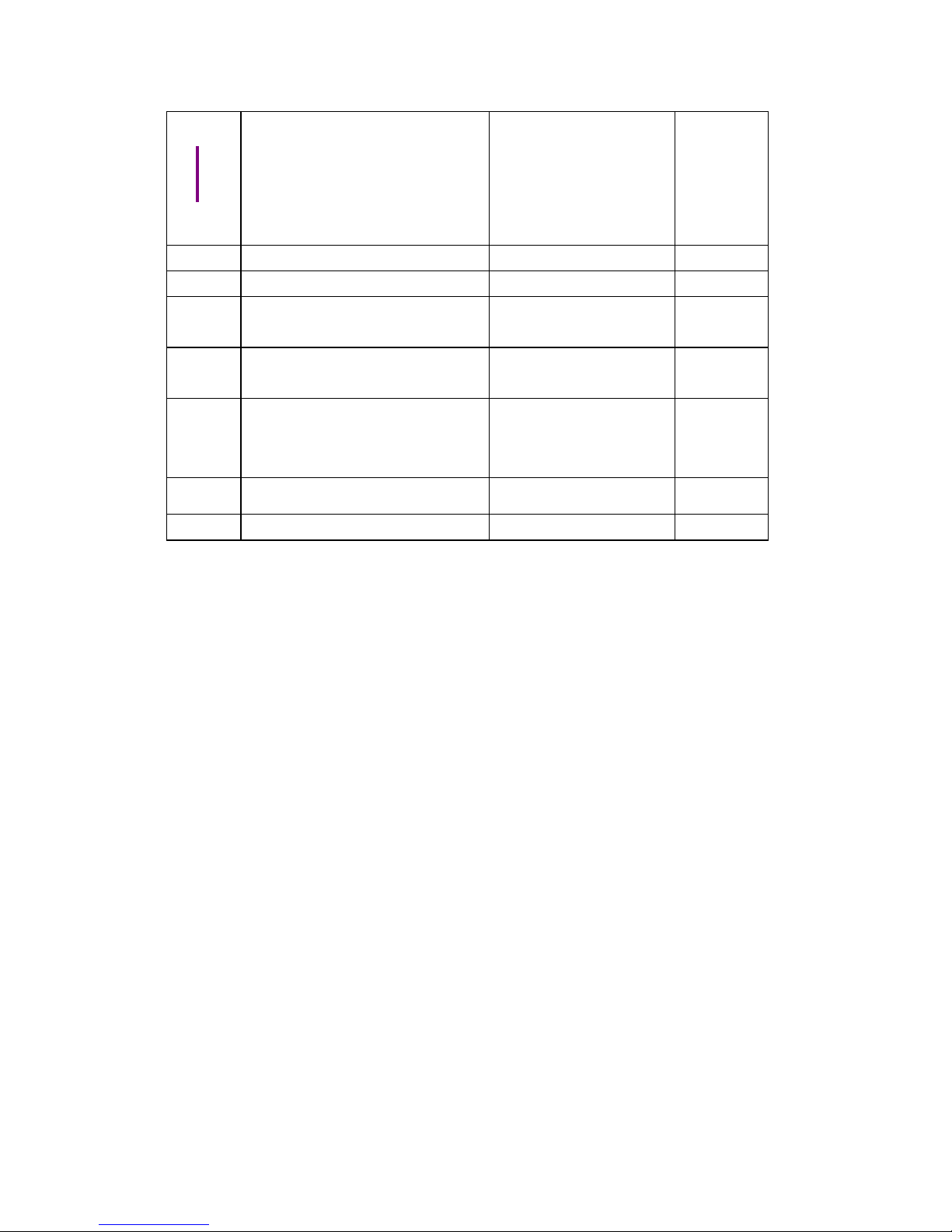
10
J32
J38
Display type Setup
Pin Header, 2.54 , 3x1 3-pin
J33 LCD Box Header,2.0 ,22x2 44-pin
CF1 Compact Flash Type I/II CF Connector 50-pin
PWR_L
ED
POWER Active LED (Red)
IDE_LED IDE Active LED (Green )
MTBF-
LED
MTBF-Out (Orange) LED-SMD
SP1 BUZZER
S1 RESET SWITCH
 Loading...