

ICOP Vortex86DX-MSJK Getting Started Manual

Vortex86DX-MSJK
Windows Embedded CE 6.0 R3
Jump Start Kit
Getting Started Guide
Samuel Phung
Windows Embedded MVP
ICOP Technology Inc.

Table of Contents
Introduction ............................................................................................................................................ 6
Vortex86DX-MSJK CE 6.0 Jump Start Kit ................................................................................................... 7
Part 1 – Development Environment Overview ......................................................................................... 9
Windows Embedded CE 6.0 R3 ............................................................................................................ 9
Windows Embedded CE 6.0 – Platform Builder .................................................................................... 9
Windows Embedded CE 6.0 – Remote Tools ...................................................................................... 10
Visual Studio 2005 Integrated Development Environment ................................................................. 10
CE 6.0 Device Development: Typical Development Steps .................................................................. 11
CE 6.0 Application Development - VS2005 and VS2008 ...................................................................... 11
The Target Device ............................................................................................................................. 11
Common Terminology ....................................................................................................................... 13
CE 6.0 Environment and Directory Variables ...................................................................................... 14
Part 2 – Development Environment Connectivity................................................................................... 15
Ethernet Connectivity ........................................................................................................................ 15
CE 6.0 OS Runtime Image Development – OS Design ................................................................. 15
CE 6.0 Application Development with Visual Studio .................................................................. 15
Serial Port Connectivity ..................................................................................................................... 15
Development Environment Setup with DHCP .................................................................................... 16
Using Wireless Access Point Router ................................................................................................... 16
Development Environment Setup with Static IP................................................................................. 17
Local Area Network without DHCP Service ................................................................................ 17
Direct Connection using Cross-Over RJ-45 Ethernet Cable ......................................................... 17
Static IP Addresses .................................................................................................................... 17
Part 3 – Required Software & Installation .............................................................................................. 18
Recommended Software Installation ................................................................................................. 18
Windows Embedded CE 6.0 Installation ............................................................................................. 19
Board-Support-Package Installation .................................................................................................. 20
SDK Installation ................................................................................................................................. 20
CoreCon Component Installation ....................................................................................................... 21
AutoLaunch Component Installation ................................................................................................. 21
RegFlushApp Component Installation ................................................................................................ 21
Part 4 – CE 6.0 OS Design Project ........................................................................................................... 22
Visual Studio 2005 ............................................................................................................................. 22
Windows Embedded CE 6.0 OS Design Wizard................................................................................... 23
Vortex86DX-MSJK Windows Embedded CE 6.0 R3 Jump Start Rev 2.2
Page 2 of 144

OS Design Wizard – Board Support Packages (BSPs) .......................................................................... 24
OS Design Wizard – Design Templates ............................................................................................... 24
OS Design Wizard – Applications & Media ......................................................................................... 25
OS Design Wizard – Networking & Communications .......................................................................... 26
Security Warning - Catalog Item Notification ..................................................................................... 27
Part 5 – Configure and Customize CE 6.0 OS Design ............................................................................... 28
Customize the OS Design – Add Additional Components ................................................................... 28
Customize the OS Design – Locate Component by Search .................................................................. 32
Customize the OS Design – Configuration Manager ........................................................................... 34
Customize the OS Design – Build Options .......................................................................................... 34
Customize the OS Design – The Registry ............................................................................................ 35
Static IP Address ................................................................................................................................ 37
Other CE 6.0 Components ................................................................................................................. 37
Part 6 – Build and Generate CE 6.0 OS Runtime Image ........................................................................... 39
The Build Process – Starting .............................................................................................................. 39
The Build Process – Completed ......................................................................................................... 39
Part 7 – Download CE 6.0 OS Runtime to Target Device ......................................................................... 41
Target Device Preparation ................................................................................................................. 41
Configure Target Device Connectivity Options ................................................................................... 42
Add New Target Device Profile .......................................................................................................... 43
Associate VDX-6326 to MyTargetDevice Connectivity Profile ............................................................. 44
Download CE 6.0 OS Runtime Image to Target Device ....................................................................... 46
Deploy CE 6.0 OS Runtime Image to Target Device ............................................................................ 48
Part 8 – Software Development Kit (SDK)............................................................................................... 49
Create and Configure CE 6.0 SDK ....................................................................................................... 49
Build and Generate CE 6.0 SDK .......................................................................................................... 51
Part 9 – Develop Native Code App with VS2005 ..................................................................................... 52
Create a New Native Code Application Project .................................................................................. 52
Add Codes and Build the Application Project ..................................................................................... 55
Preparing Target Device to Connect to VS2005 IDE ............................................................................ 56
Configure VS2005 Device Connectivity Settings ................................................................................. 58
Establish Connectivity to CE 6.0 Target Device ................................................................................... 59
Download Application to Target Device ............................................................................................. 60
Part 10 – Develop Managed Code App with VS2005 .............................................................................. 61
Create a New Managed Code Application Project .............................................................................. 61
Vortex86DX-MSJK Windows Embedded CE 6.0 R3 Jump Start Rev 2.2
Page 3 of 144

Add Codes and Build the Application Project ..................................................................................... 62
Preparing Target Device to Connect to VS2005 IDE ............................................................................ 63
Configure VS2005 Device Connectivity Settings ................................................................................. 63
Establish Connectivity to CE 6.0 Target Device ................................................................................... 63
Download Application to Target Device ............................................................................................. 65
Debug Application Running on Target Device .................................................................................... 65
Part 11 – Develop Native Code App with VS2008 ................................................................................... 69
Create a New Native Code Application Project .................................................................................. 69
Add Codes and Build the Application Project ..................................................................................... 72
Preparing Target Device to Connect to VS2008 IDE ............................................................................ 73
Configure VS2008 Device Connectivity Settings ................................................................................. 75
Establish Connectivity to CE 6.0 Target Device ................................................................................... 76
Download Application to Target Device ............................................................................................. 77
Part 12 – Develop Managed Code App with VS2008 .............................................................................. 79
Create a New Managed Code Application Project .............................................................................. 79
Add Codes and Build the Application Project ..................................................................................... 81
Preparing Target Device to Connect to VS2008 IDE ............................................................................ 82
Configure VS2008 Device Connectivity Settings ................................................................................. 82
Establish Connectivity to CE 6.0 Target Device ................................................................................... 82
Download Application to Target Device ............................................................................................. 83
Debug Application Running on Target Device .................................................................................... 84
Part 13 – Debug and Remote Tools ........................................................................................................ 88
Download KITL Enabled CE 6.0 OS Image to Target Device ................................................................. 88
Remote Tool: Process Viewer ........................................................................................................... 89
Remote Tool: Registry Editor ............................................................................................................ 90
Remote Tool: System Information .................................................................................................... 91
Congratulations! – You’ve completed all the steps ................................................................................ 93
Appendix A – Development Workstation Setup with DHCP .................................................................... 94
Connecting to Local Area Network with DHCP ................................................................................... 94
Using Wireless Access Point Router ................................................................................................... 94
Capturing Serial Debug Messages ...................................................................................................... 95
Appendix B – Development Workstation Setup with Static IP ................................................................ 96
Connecting to Ethernet Hub or Switch without DHCP ........................................................................ 96
Direct Connection with Cross-Over RJ-45 Ethernet Cable ................................................................... 96
Static IP Address ................................................................................................................................ 97
Vortex86DX-MSJK Windows Embedded CE 6.0 R3 Jump Start Rev 2.2
Page 4 of 144

Capturing Serial Debug Messages ...................................................................................................... 97
Appendix C – Windows Embedded CE Resources ................................................................................... 98
Appendix D – VDX-6326 SBC Technical Information ............................................................................. 100
Appendix E – VDX-6326 SBC Startup Options ....................................................................................... 115
Appendix F – BIOSLoader Boot Options ............................................................................................... 116
Primary BIN File ............................................................................................................................... 116
Alternative BIN File ......................................................................................................................... 116
Appendix G – Using Static IP Address ................................................................................................... 118
Configure Static IP for Prebuilt CE 6.0 OS Runtime ........................................................................... 118
Configure OS Design with Static IP Address ..................................................................................... 119
Appendix H – Deploy OS Runtime with DiskPrep .................................................................................. 120
Appendix I – CoreCon Connectivity ...................................................................................................... 123
Appendix J – Recover Jump Start Kit’s Original Files ............................................................................. 125
Vortex86DX-MSJK Preconfigured Files ............................................................................................. 125
Recover Damaged Files ................................................................................................................... 125
Preparing USB Flash Storage to Boot to DOS ................................................................................... 126
Configure VDX-6326 SBC to Boot from USB Flash Storage ................................................................ 127
Boot Device Priority ........................................................................................................................ 129
Steps to Recover All Files (USB Flash boot to DOS) ........................................................................... 130
Recover Files with DiskPrep ............................................................................................................. 132
Appendix K – VDX-6326 SBC System BIOS ............................................................................................ 133
Appendix L – Using Watchdog Timer ................................................................................................... 135
Using WDT0 .................................................................................................................................... 135
Using WDT1 .................................................................................................................................... 136
WDT.dll ........................................................................................................................................... 137
Appendix M – Using GPIO .................................................................................................................... 138
Using the GPIO ................................................................................................................................ 138
Windows Embedded CE Sample Codes.................................................................................... 138
Configure GPIO to Output Mode ............................................................................................. 138
Configure GPIO to Intput Mode............................................................................................... 140
GPIO.DLL ......................................................................................................................................... 140
Appendix N – Modify DOS Startup Option ........................................................................................... 142
Vortex86DX-MSJK Windows Embedded CE 6.0 R3 Jump Start Rev 2.2
Page 5 of 144

Introduction
This getting started guide, with hands-on exercises written in step by step format, is created to show
how to develop Windows Embedded CE 6.0 R3 (CE 6.0) OS design, generate customized runtime image
from the OS design, configure the development environment to download the runtime image to a target
device and CE 6.0 application development.
The following subjects are covered in this guide:
•
What’s included in the jump start kit.
•
Development environment overview.
•
Required software and recommended installation sequences.
•
Develop and configure CE 6.0 OS design project
•
Generate CE 6.0 OS runtime image from the OS design project
•
Establish connectivity and download OS runtime image from the development workstation to
target device.
•
Develop manage and native code application for CE 6.0 using Visual Studio 2005, establish
connectivity and download the application to target device.
•
Develop manage and native code application for CE 6.0 using Visual Studio 2008, establish
connectivity and download the application to target device.
•
Debugging and Remote Tools for CE 6.0.
While it’s possible to use the emulator or VirtualPC as the target device and work through similar
exercises, a real hardware provides a more practical learning environment. The VDX-6326 single-boardcomputer, configured with the necessary software components, is used as the target device for the
exercises in this guide.
The exercises in this guide are tested on 32-bit version of Windows XP, Windows Vista and Windows 7
development workstation. The CE 6.0 development tools are not designed to support 64-bit version of
the Windows XP, Windows Vista and Windows 7 OS.
To minimize unnecessary problem caused by missing software components and improper development
environment configuration, follow the recommended software installation sequences and development
environment setup provided as part of this getting started guide.
The primary objective for this guide is to show you the different development facility available as part of
the CE 6.0 and Visual Studio 2005 to support CE 6.0 development tasks.
It’s not within this guide’s objective to talk about programming languages and concept. Short and
simple exercises are used in this guide to provide direct and to the point information about the covered
subject matter.
Update to this getting started guide and other CE 6.0 resources are available from the following:
http://www.embeddedpc.net/Vortex86DXMSJK/
Vortex86DX-MSJK Windows Embedded CE 6.0 R3 Jump Start Rev 2.2
Page 6 of 144

Vortex86DX-MSJK CE 6.0 Jump Start Kit
The Vortex86DX-MSJK CE 6.0 jump start kit includes the following:
•
VDX-6326, an 800 MHz single-board-computer (SBC), built with the following features:
o
800 MHz Vortex86DX System-On-Chip
o
XGI Z9s Video with VGA output
o
256MB soldered on DDR2 system memory
o
Enhanced IDE (UltraDMA-100/66/33) interface
o
CM119 USB Audio
o
Onboard 4MB SPI flash
o
Three 10/100Mbps Ethernet interfaces
o
Three USB 2.0 Host interfaces
o
Three RS-232 Serial ports and one RS-232/422/485 serial port
o
Parallel port
o
16-bit GPIO (Can be configured as PWM)
o
Internal Mini-PCI expansion slot
o
Type I/II Compact Flash slot (Support storage card only)
o
PC/104 expansion bus
o
PS/2 keyboard & mouse interface
o
Two watchdog timers (Programmable from 30.5µs to 512 seconds
•
Enclosure to house the VDX-6326 SBC
•
Power supply (supports 100~240VAC 50/60 Hz input)
•
512 MB Compact Flash
The 512 MB Compact Flash is preconfigured with Loadcepc bootloader to launch a prebuilt CE 6.0 OS
runtime image. In addition, the Compact Flash also included an Ethernet bootloader, needed to support
custom OS development to download OS runtime image from the development workstation to the target
device.
•
One RJ-45 Ethernet Crossover cable
With a crossover Ethernet cable and proper static IP address settings, the target device can be connected
directly to the development workstation and create a standalone development environment with support
to download CE 6.0 OS runtime image and deploy application to the target device from the development
workstation.
•
One RS-232 null serial cable for serial debug
The RS-232 null serial cable is used to establish connectivity between one of the serial port on the target
device to an available serial port on the development workstation. With proper configuration, debug
messages from target device can be captured by the development workstation using Hyper Terminal or
similar application.
•
Windows Embedded CE 6.0 R3 MSJK software kit, which includes the following:
o
Windows Embedded CE 6.0 R3 (180 days evaluation version) development software.
The evaluation version of the CE 6.0 software is fully functional. Other than the 180 days usage
limit, it has all of the function and feature as the full version.
o
Vortex86DX-MSJK Windows Embedded CE 6.0 R3 jump start CD – This jump start CD
includes the following:
Vortex86DX-MSJK Windows Embedded CE 6.0 R3 Jump Start Rev 2.2
Page 7 of 144

VDX-6326 SBC Board-Support-Package (BSP) for CE 6.0
VDX-6326 SDK for CE 6.0
CoreCon component for CE 6.0
AutoLaunch component for CE 6.0
Sample project codes for the exercises in this guide
Note: Kit contents and specifications are subject to change without notice.
Vortex86DX-MSJK Windows Embedded CE 6.0 R3 Jump Start Rev 2.2
Page 8 of 144

Part 1 –
All CE 6.0 development tasks are supported within the VS2005 IDE, a developer friendly, efficient and
intuitive development environment with templates and wizard to help simplify complicate development
tasks.
Development Environment Overview
Windows Embedded CE 6.0 R3
Windows Embedded CE 6.0 R3 (CE 6.0) is a hard Real-time operating system with ability to handle
32,000 concurrent processes and 2GB memory footprint for each process. CE 6.0 delivers reliable,
secure performance in a small footprint package along with the latest networking, multimedia and
communications technologies. CE 6.0 provides broad range of device support with enhanced
features, including robust file system, Web services for device, voice over IP phone, network
gateway configurations, platform development tool enhancements, greater application
compatibility with other Windows Embedded CE based devices, Internet Explorer, Windows Media
CODECs, Microsoft .NET Compact Framework, and a number of other newly supported protocols
and services.
In addition to improvement to the OS and development tool, the CE 6.0 R3 release added the
following components:
•
Silverlight for Windows Embedded
•
Flash Lite Browser plug-in to render Flash contents
•
Touch and Gesture
•
Microsoft Office application files viewers
•
PDF file viewer
•
QQ Messenger
•
Connection Manager
Combining large pool of production quality BSP, device drivers, programming libraries and efficient
development tools, CE 6.0 provides the ideal Rapid Application Development environment to help
create the next generation of smart, media rich, connected and service oriented devices. For more
information about CE 6.0, visit:
http://www.microsoft.com/windowsembedded/en-us/products/windowsce/default.mspx
Windows Embedded CE 6.0 – Platform Builder
Platform Builder is the development tool used to develop CE 6.0 OS design project and generate
custom CE 6.0 OS runtime image from the OS design project. It also provides the remote tools to
debug CE 6.0 OS runtime image on a target device, built with Kernel Independent Transport Layer
(KITL) enabled.
Windows Embedded CE Platform Builder releases prior to CE 6.0 are standalone development tool.
For the CE 6.0 release, Platform Builder is a plug-in to the VS2005 IDE, and requires the VS2005 IDE
to function.
Vortex86DX-MSJK Windows Embedded CE 6.0 R3 Jump Start Rev 2.2
Page 9 of 144

Windows Embedded CE 6.0 – Remote Tools
Using remote tools provided as part of the CE 6.0 development environment, developer is able to
remotely debug CE 6.0 OS runtime image running on a target device, built with KITL enabled.
The following remote tools are provided as part of the CE 6.0 development environment:
•
Remote Call Profiler
•
Remote File Viewer
•
Remote Heap Walker
•
Remote Kernel Tracker
•
Remote Performance Monitor
•
Remote Process Viewer
•
Remote Registry Editor
•
Remote Spy
•
Remote System Information
•
Remote Zoom-in
Visual Studio 2005 Integrated Development Environment
VS2005 is a popular developer friendly development tool to develop broad range of applications
that can run on different version of the Windows operating system. Using the VS2005 IDE,
developer is able to create applications for the following Windows operating system:
•
Windows 95, Windows 98, Windows ME and Windows 2000 legacy operating system.
•
Windows XP
•
Windows Vista
•
Windows 2000 Server
•
Windows 2003 Server
•
Windows 2008 Server
•
PocketPC
•
Windows Mobile Smartphones
•
Windows Embedded CE devices
•
Etc…
The VS2005 IDE provides a centralized development environment to develop broad range of
applications, such as:
•
Windows Form application
•
Win32, ATL and MFC project
•
DLL, ActiveX control, ASP.NET Web service, Windows service
•
SQL Server project, Console application, Class libraries
•
Windows Embedded CE and Mobile Smart Device application,
•
Windows Embedded CE OS design
•
Etc…
Vortex86DX-MSJK Windows Embedded CE 6.0 R3 Jump Start Rev 2.2
Page 10 of 144

CE 6.0 Device Development: Typical Development Steps
Here are the typical steps to develop a CE 6.0 device after the hardware platform is selected:
•
Develop CE 6.0 BSP for the selected hardware (some hardware vendors provide BSP to
support their hardware).
•
Create and customize an OS design project for the hardware.
•
Generate customized CE 6.0 OS runtime image for the hardware.
•
Deploy CE 6.0 OS runtime image to the hardware for testing and debug.
•
Generate CE 6.0 SDK from the OS design to support application development.
•
Application development can take place concurrently, using VS2005 or VS2008, as the
hardware and OS design being fine tuned.
•
After the satisfied CE 6.0 OS runtime image and application are created, deploy the solution
to the final hardware.
CE 6.0 Application Development - VS2005 and VS2008
Both VS2005 and VS2008 support application development for CE 6.0 device. There are multiple
options to develop CE 6.0 applications.
•
Develop Native code application with C programming language.
•
Develop Native code application with Visual C++, using the VS2005 IDE.
•
Develop Managed code application with Visual C#, using the VS2005 IDE.
•
Develop Managed code application with Visual Basic, using the VS2005 IDE.
•
Develop Native code application with Visual C++, using the VS2008 IDE.
•
Develop Managed code application with Visual C#, using the VS2008 IDE.
•
Develop Managed code application with Visual Basic, using the VS2008 IDE.
A Software Development Kit (SDK), generate from the OS design for the target device, is needed to
support application development for the target device using VS2005 or VS2008.
The Visual Studio IDE provides an efficient development environment, making it possible to
download the application from the IDE to the target device for testing and debug using CoreCon
connectivity.
Using the Visual Studio IDE with CoreCon connectivity, application developer is able deploy
application to a CE 6.0 target device, launches the application, set breakpoint, executes the
application codes and stepping through the codes one-line-at-a-time while it’s running on the target
device.
The Target Device
The term target device is referring to the hardware platform used in a CE 6.0 development project.
For the exercises in this guide, the VDX-6326 SBC is used as the target device.
The
ICOP_VDX6326_60B
drivers and configuration files to support CE 6.0 OS development for the VDX-6326 SBC, is used for
the exercises in this guide, as shown in Figure 1.
BSP which includes the necessary hardware adaptation codes, device
Vortex86DX-MSJK Windows Embedded CE 6.0 R3 Jump Start Rev 2.2
Page 11 of 144
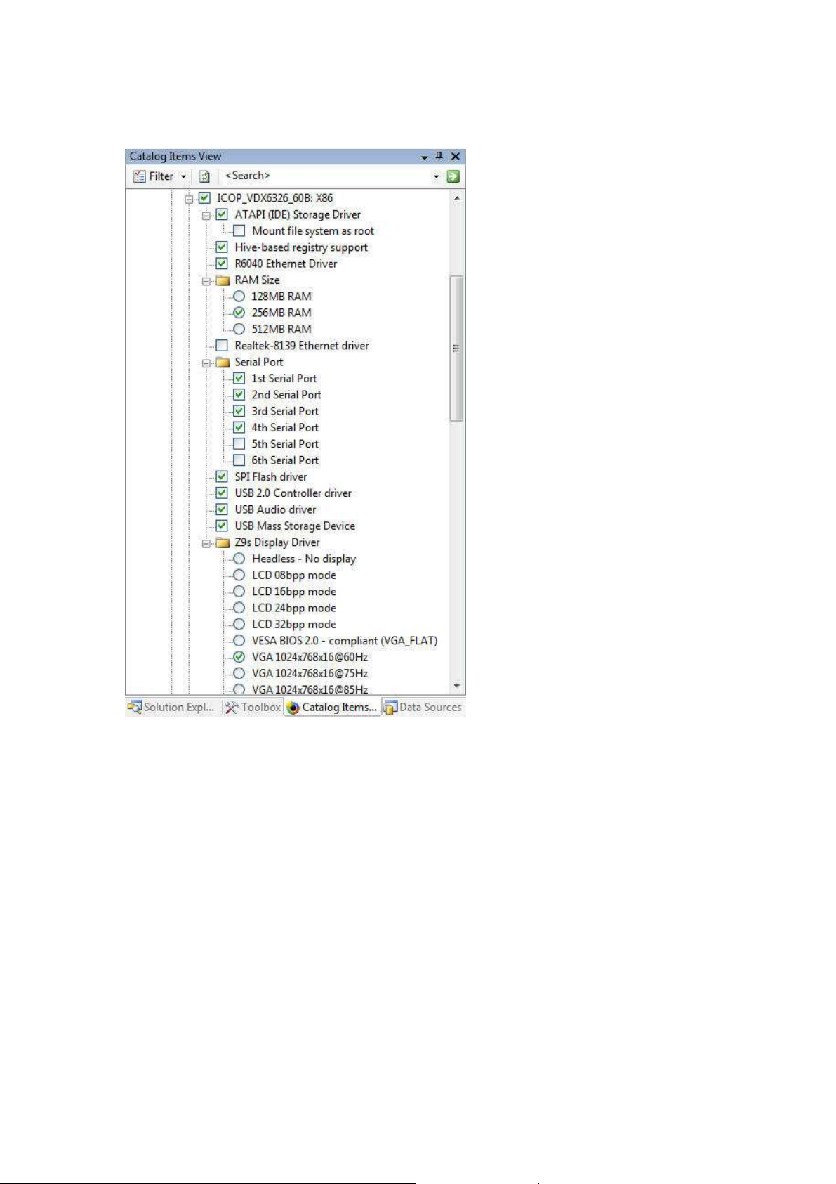
Fig. 1 – ICOP_VDX6326_60B BSP for CE 6.0
In addition to the device drivers, the following DLLs are provided to help developers access the VDX6326 SBC’s GPIO and Watchdog timers:
•
GPIO.dll (To access the 16-bit GPIOs)
•
IO.dll (To access the VDX-6326 SBC’s hardware I/O)
•
WDT.dll (To access the Watchdog timers)
When developing an OS design with the ICOP_VDX6326_60B BSP, these DLLs are included to the OS
design and compile into the OS runtime image by default.
Sample native and managed code projects showing how to use these DLLs are provided on the jump
start CD-ROM.
Refer to appendix L and M for more information about GPIO and watchdog timer.
Vortex86DX-MSJK Windows Embedded CE 6.0 R3 Jump Start Rev 2.2
Page 12 of 144

Common Terminology
Abbreviation/ key word
Description and Representation
“Windows Embedded CE 6.0”
, “
Windows Embedded
CE 6.0 R2” and
VS2005
Visual Studio 2005
VS2008
Visual Studio 2008
IDE Integrated Development Environment
Board
Support Package:
A group of Windows Embedded CE
software
OAL OEM Adaptation Layer
Component can be a device driver, BSP,
programming library,
The component catalog lists all of the components provided by Platform
OS design is a Platfor
m Builder project, containing components that
Refer to the physical hardware for runnin
g the CE 6.0 OS and
Refer to the device used in the CE 6.0 development environment. When
SBC Short for Single
-
Board
-
Computer.
The binary file generated from the OS design project
to deploy to the
Referring to the directory where all files related to the OS design
To minimize the need to write long description to identify the product or component, it’s a common
practice for developer in different industry to use abbreviated key word. To the new comer, without
knowing the terminology used and what the abbreviated key words represent can cause quite a bit
of confusion.
The following table contains abbreviation for some of the common key words used in the CE 6.0
development environment and within this jump start kit:
CE 6.0
BSP
Component
Catalog
OS design
Hardware Platform
Target Device
“Windows Embedded CE 6.0 R3”
components that includes the OEM adaptation layer code, device drivers
and configuration files, needed to create the OS design project to
generate OS runtime image for the targeted hardware.
application, utility, configuration settings, fonts, etc... The OS design is
made up by a group of components.
Builder and installed 3rd party components. The component catalog
provides the interface to add components to the OS design project and
remove components from the project. This is also the interface to view
which components are included to the OS design project.
make up the OS runtime image. Windows Embedded CE OS runtime
image is generated from an OS design project.
application, also refer to as the target device.
working on exercise using an emulator, the emulator is the target
device. Virtual PC can be a target device for the CE 6.0 development
environment. For the exercise in this guide, the VDX-6326 SBC is the
target device.
OS Runtime Image
Release Directory or
Build Release Directory
target device.
projects are placed by the build tools prior to compiling the OS runtime
image.
Vortex86DX-MSJK Windows Embedded CE 6.0 R3 Jump Start Rev 2.2
Page 13 of 144

CE 6.0 Environment and Directory Variables
Variable Name
Description
- Purpose
Configure the OS design to
include the stub display driver
Configure the OS design to exclude all audio components from the
Configure the OS design to generate runtime image supporting
PRJ_ENABLE_
FSREGHIVE
Configure the OS design to enable Hive
-
based registry support
Defines the root directory for the CE 6.0 install. The default directory
Within the CE 6.0 development environment, environment variables are used to configure the OS
design to include, exclude associated components and control certain system behaviors. Directory
variables representing the associated directory are used to help make the codes and script easier to
understand and read. Here are some of these variables:
BSP_DISPLAY_NOP
BSP_NOAUDIO
IMGRAM256
_WINCEROOT
(DDI_NOP.dll) to support headless device.
build.
256MB of RAM
is:
C:\WINCE600
The above table lists a small sampling of variables used in the CE 6.0 development environment. For
more information about these environment variables, visit the following URLs:
About Environment Variables:
http://msdn.microsoft.com/en-us/library/ee479020.aspx
BSP Environment Variables:
http://msdn.microsoft.com/en-us/library/ee478674.aspx
BSP_NO Environment Variables:
http://msdn.microsoft.com/en-us/library/ee478672.aspx
IMG Environment Variables:
http://msdn.microsoft.com/en-us/library/ee479025.aspx
PRJ Environment Variables:
http://msdn.microsoft.com/en-us/library/ee479112.aspx
Miscellaneous Environment Variables:
http://msdn.microsoft.com/en-us/library/ee479008.aspx
Vortex86DX-MSJK Windows Embedded CE 6.0 R3 Jump Start Rev 2.2
Page 14 of 144

Part 2 –
It’s important to establish a proper development environment and understand different options
available to establish connectivity between the development workstation and target device to download
CE 6.0 OS runtime image, and deploy application, from the development workstation to the target
device for testing and debug. In this section, we will cover some of the common connectivity for the CE
6.0 development environment.
Development Environment Connectivity
Ethernet Connectivity
For the exercises in this guide, Ethernet is the primary connectivity in use for CE 6.0 development
with both the development workstation and target device connected to the same Local Area
Network.
CE 6.0 OS Runtime Image Development – OS Design
OS Design is one of the project type supported by the VS2005 IDE, to generate customized CE
6.0 OS runtime Image.
As part of the OS design development process, connectivity between the development
workstation and target device is needed to download the OS runtime image to the target device
and debug. While it’s possible to use the serial port and other connectivity, Ethernet connection
is one of the practical options for debugging and downloading OS runtime image from the
development workstation to the target device for testing and debug.
CE 6.0 Application Development with Visual Studio
Both Visual Studio 2005 and 2008 support CE 6.0 managed and native code application
development, and able to deploy application from the development workstation to the target
device for testing and debug, using an Ethernet connection.
As part of the application development exercises in this guide, CoreCon connectivity established
over the Ethernet connection is used to transport VS2005 and VS2008 application from the
development workstation to the target device and provides connectivity for debugging.
VDX-6326 SBC Connectivity
The VDX-6326 SBC has 3 built-in Ethernet interfaces. One of the interfaces uses the R6040 Ethernet
controller, built-in to the Vortex86DX SoC, and uses the R6040 Ethernet driver provided as part of
the ICOP_VDX6326_60B BSP. The other two interfaces use Realtek-8100 controller, supported by
the Realtek-8139 (RTL-8139) Ethernet driver provided by the Platform Builder.
For the exercises in this guide, the R6040 Ethernet interface is used. The R6040 Ethernet interface is
located on the back of the enclosure, between the USB and PS/2 interfaces.
Serial Port Connectivity
Serial port connectivity is established by connecting a null RS-232 serial modem cable between one
of the target device’s serial ports and an available serial port on the development workstation.
Serial connection is useful for debugging headless device and startup process during the bootloader
phase where the CE 6.0 OS runtime has not been fully launched.
Vortex86DX-MSJK Windows Embedded CE 6.0 R3 Jump Start Rev 2.2
Page 15 of 144
A Hyper-Terminal or similar application, running on the development workstation, is used to capture
Note:
The wireless
-
access
-
point-router device’s
routing function filter and route network packets based
serial debug messages from the target device.
Development Environment Setup with DHCP
It’s common to setup the development environment where the development workstation and
target device are connected to the same Local Area Network with DHCP service, with a null RS-232
serial modem cable connected from one of the serial port on the target device and an available
serial port on the development workstation.
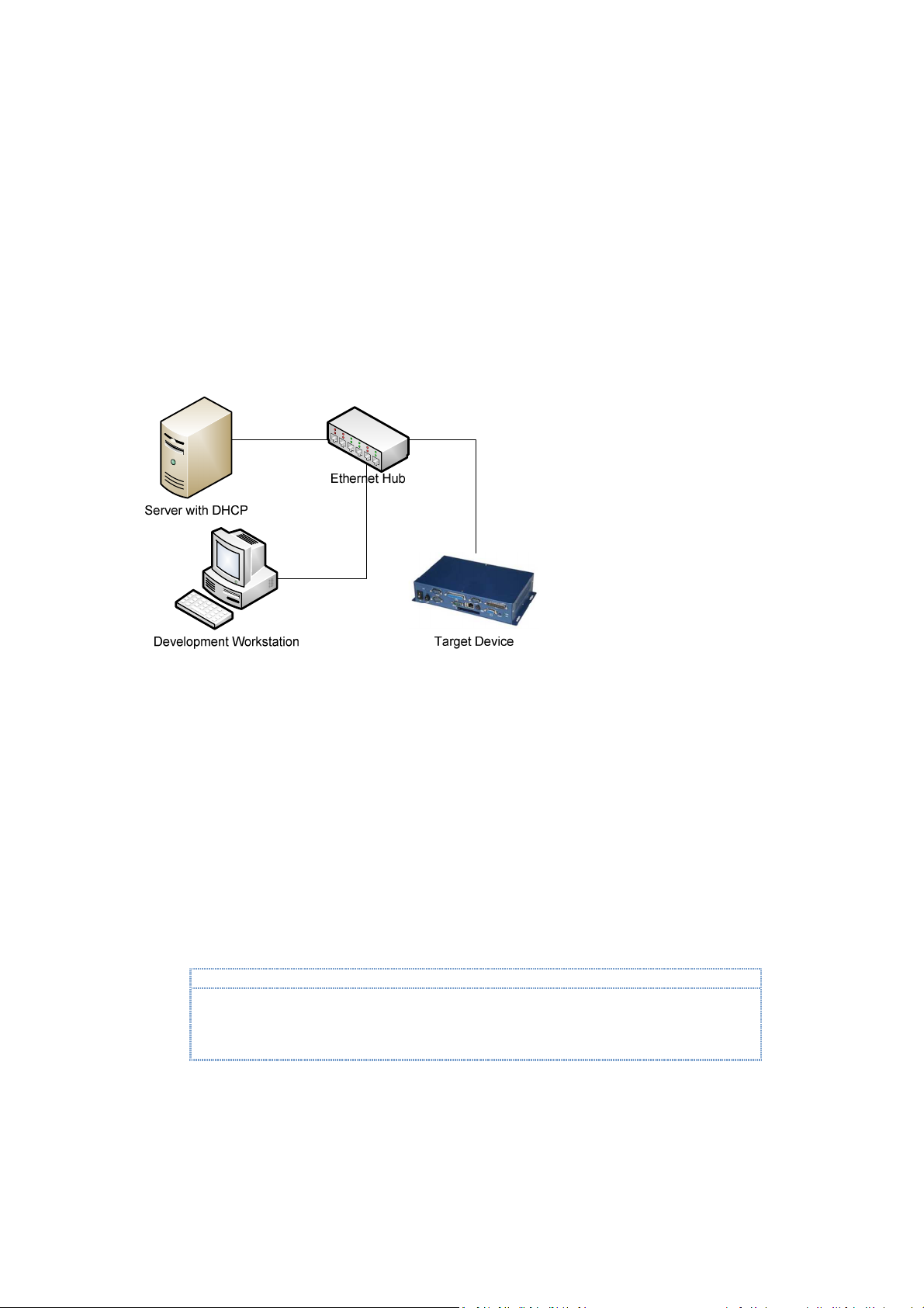
Here is a typical setup to connect both the development workstation and target device to a Local
Area Network with DHCP service, as shown in Figure 2.
Fig. 2 - Development environment with DHCP service provider
If the target device fails to establish connectivity with the development workstation as expected
with this configuration, it may be caused by one of the following:
•
The development workstation’s firewall software may be blocking the connection.
•
DHCP service for the target device needs to be enabled on your network. Some secured
network may require the target device’s MAC address to be added to the authorized device
list to be serviced by the DHCP server.
Using Wireless Access Point Router
When using a wireless-access-point-router with multiple Ethernet ports, connecting both the
development workstation and target device directly to the Ethernet port on the wireless-accesspoint-router may be problematic with certain model of access point, and prevent the development
environment from functioning as expected.
on the packet’s associated origin, destination and other information. In some router, the routing
algorithm may prevent some of the packets between the development workstation and target
device from reaching its destination and cause problem.
Instead of connecting directly to the wireless-access-point-router device’s Ethernet ports, attach an
Ethernet network hub to the wireless-access-point-router device, to access the DHCP service
provided by the wireless-access-point-router, and connect both the development workstation and
Vortex86DX-MSJK Windows Embedded CE 6.0 R3 Jump Start Rev 2.2
Page 16 of 144
target device to the Ethernet network hub. With both the development workstation and target
device connecting to the same Ethernet hub, the network traffics between them are not filtered.
Development Environment Setup with Static IP
It’s possible to establish a CE 6.0 development environment with Static IP addresses. Here are two
scenarios for setting up the development environment using static IP addresses:
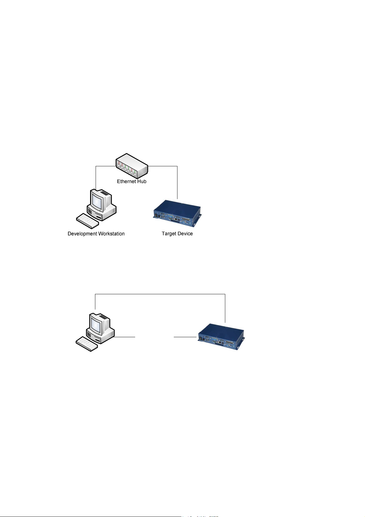
Local Area Network without DHCP Service
The development workstation and target device are connected to the same Local Area Network
or an Ethernet Hub, without DHCP service, as shown in Figure 3.
Fig. 3 - Local Area Network without DHCP
Direct Connection using Cross-Over RJ-45 Ethernet Cable
Connectivity can be established by attaching the target device to the development workstation
directly, using a cross-over RJ-45 Ethernet cable and proper static IP addresses configuration, as
shown in Figure 4.
Cross over RJ-45
Ethernet cable
Null RS-232
Serial Modem Cable
Development Workstation Target Device
Fig. 4 - Direct connection with cross-over RJ-45 Ethernet cable
Static IP Addresses
Without DHCP service to assign IP addresses dynamically, the target device and development
workstation must be configured with appropriate static IP addresses in order to establish
connectivity.
To establish connectivity to the target device, both the development workstation and target
device must be configured with static IP addresses within the same subnet.
Refer to appendix G for more information about using static IP addresses.
Vortex86DX-MSJK Windows Embedded CE 6.0 R3 Jump Start Rev 2.2
Page 17 of 144

Part 3 – Required Software & Installation
The following software components are required to develop CE 6.0 solution, and needed to work
through the exercises in this getting started guide:
•
Visual Studio 2005 with Service Pack 1
•
Windows Embedded CE 6.0 R3
•
ICOP_VDX6326_60B_BSP.msi
•
MyWinCE600_SDK.msi
•
CoreCon_v200_x86_WINCE600.msi
•
AutoLaunch_v200_x86_WINCE600.msi
•
RegFlushApp_v100_x86_WINCE600.msi
Recommended Software Installation
It’s important to install the software in their proper sequences. Here is the recommended software
installation sequence:
•
Visual Studio 2005
•
Visual Studio 2005 SP1
If you have the full retail or evaluation version of Windows Embedded CE 6.0 R2 or R3, The VS2005
SP1 installation file is provided on one of the DISC. Otherwise, download from following URL:
http://www.microsoft.com/downloads/details.aspx?FamilyID=bb4a75ab-e2d4-4c96-b39d37baf6b5b1dc&DisplayLang=en
•
Visual Studio 2005 SP1 update for Vista
If you are using a Windows XP workstation, skip this step.
If you have the full retail or evaluation version of Windows Embedded CE 6.0 R2 or R3, The VS2005
SP1 update for Vista installation file is provided on one of the DISC. Otherwise, download from
following URL:
http://www.microsoft.com/downloads/details.aspx?displaylang=en&FamilyID=90e2942d-3ad1-4873-a2ee4acc0aace5b6
•
Windows Embedded CE 6.0
•
Windows Embedded CE 6.0 SP1
If you have the full retail or evaluation version of Windows Embedded CE 6.0 R2 or R3, The CE 6.0 SP1
is provided on one of the DISC. Otherwise, download from the following URL:
http://www.microsoft.com/downloads/details.aspx?FamilyID=bf0dc0e3-8575-4860-a8e3290adf242678&DisplayLang=en
•
Windows Embedded CE 6.0 R2
If you have the full retail or evaluation version of Windows Embedded CE 6.0 R2 or R3, The CE 6.0 R2
update is provided on one of the DISC. Otherwise, download from the following URL:
http://www.microsoft.com/downloads/details.aspx?FamilyID=f41fc7c1-f0f4-4fd6-9366b61e0ab59565&DisplayLang=en
•
Windows Embedded CE 6.0 R3
Vortex86DX-MSJK Windows Embedded CE 6.0 R3 Jump Start Rev 2.2
Page 18 of 144
If you have the full retail or evaluation version of Windows Embedded CE 6.0 R3, The CE 6.0 R3
update is provided on one of the DISC. Otherwise, download from the following URL:
http://www.microsoft.com/downloads/details.aspx?displaylang=en&FamilyID=bc247d88-ddb6-4d4a-a5958eee3556fe46
•
ICOP_VDX6326_60B_BSP.msi
This BSP is provided on the jump start kit CD, in the
•
MyWinCE600_SDK.msi
This SDK is provided on the jump start kit CD, in the
•
CoreCon_v200_x86_WinCE600.msi
This CoreCon component is provided on the jump start kit CD, in the
•
AutoLaunch_v200_x86_WinCE600.msi
This AutoLaunch component is provided on the jump start kit CD, in the
•
RegFlushApp_v100_x86_WinCE600.msi
This RegFlushApp component is provided in the jump start kit CD, in the
\Software
\Software
folder.
folder.
\Software
folder.
\Software
\Software
folder.
folder.
Windows Embedded CE 6.0 Installation
Since the CE 6.0 development tool, Platform Builder, is a plug-in to the VS2005 IDE
VS2005 development tool must be installed to the develop workstation prior to installing the CE 6.0
software packages. While the CE 6.0 installation does not require VS2005 SP1 to be installed, it’s
required to install SDK generated from the CE 6.0 OS design. The SDK is needed to support VS2005
and VS2008 application development. For Windows Vista workstation, VS2005 SP1 Update for Vista
is also needed.
, the
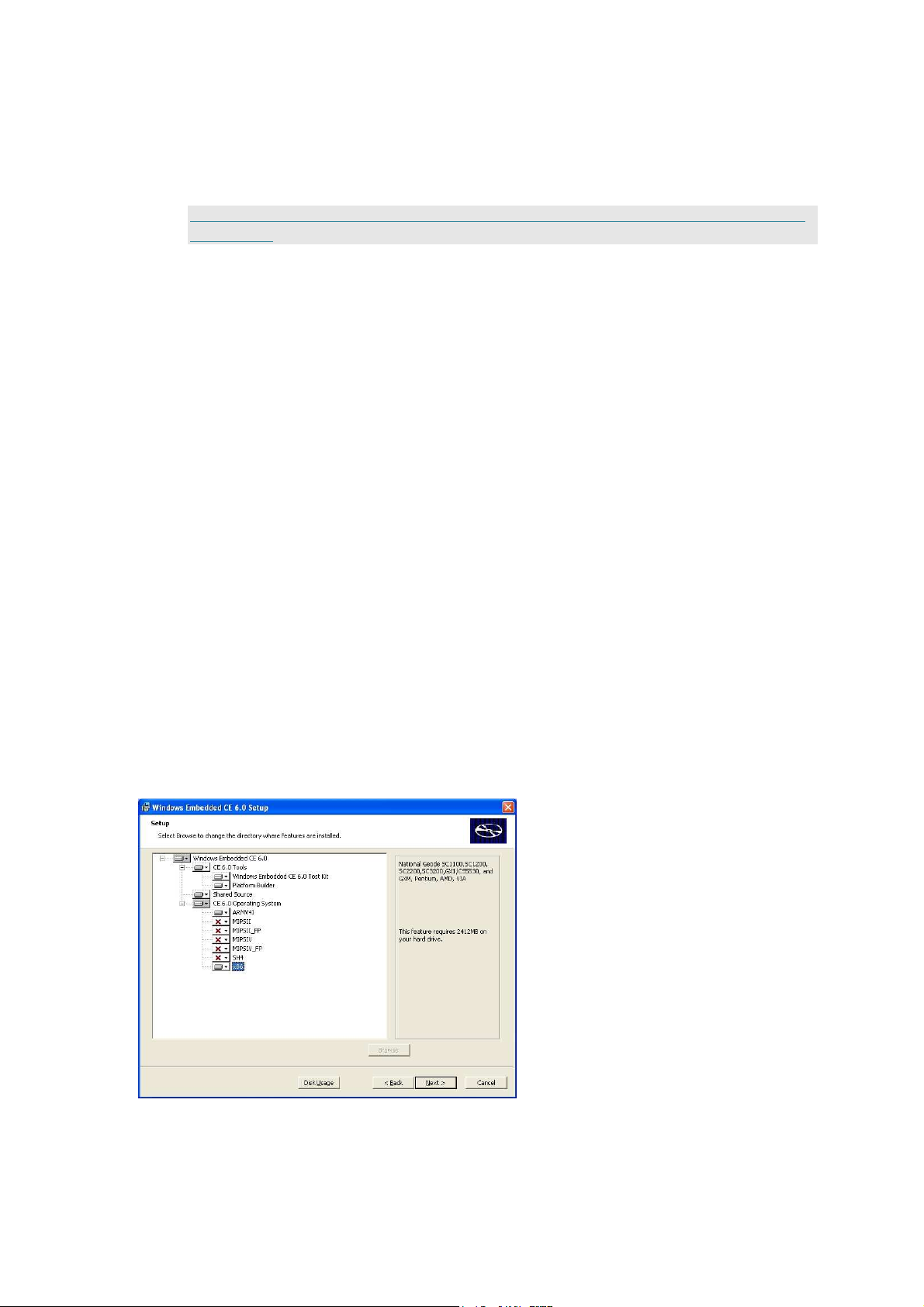
By default, the CE 6.0 installation program only selects and includes support for the ARMV4I
processor during installation. The VDX-6326 SBC is built with an x86 processor. Support for the x86
processor must be selected and included as part of the installation in order to work through the
exercises in this guide.
When installing the CE 6.0 software, during the supported processor selection step, include support
for the x86 processor, as shown in Figure 5.
Fig. 5 - Windows Embedded CE 6.0 setup
Vortex86DX-MSJK Windows Embedded CE 6.0 R3 Jump Start Rev 2.2
Page 19 of 144

Note:
It’s strongly recommended to install all software to the default installation directory. Some of the 3
rd
party components used for the exercises in this guide assume all software components are installed to
Note:
x86 CPU support for CE 6.0 PLATFORM BUILDER is needed in order to use
ICOP_
VDX6326_60B
BSP to create
the default directory. When the software components are installed to a different directory, these 3rd
party components may not function as expected.
Windows Embedded CE 6.0 SP1 Installation
After installing the CE 6.0 software, install the CE 6.0 SP1 update. Depending on the version of
CE 6.0 CD or DVD being used to install the software, the CE 6.0 SP1 update may be provided as
part of the CD or DVD. Otherwise, download and install CE 6.0 SP1 from the following URL:
http://www.microsoft.com/downloads/details.aspx?FamilyID=bf0dc0e3-8575-4860-a8e3290adf242678&DisplayLang=en
Windows Embedded CE 6.0 R2 Installation
After installing the CE 6.0 SP1, install the CE 6.0 R2 update. Depending on the version of CE 6.0
CD or DVD being used to install the software, the CE 6.0 R2 update may be provided as part of
the CD or DVD. Otherwise, download and install CE 6.0 R2 from the following URL:
http://www.microsoft.com/downloads/details.aspx?FamilyID=f41fc7c1-f0f4-4fd6-9366b61e0ab59565&DisplayLang=en
Windows Embedded CE 6.0 R3 Installation
After installing the CE 6.0 R2, install the CE 6.0 R3 update. Depending on the version of CE 6.0
CD or DVD being used to install the software, the CE 6.0 R3 update may be provided as part of
the CD or DVD. Otherwise, download and install CE 6.0 R3 from the following URL:
http://www.microsoft.com/downloads/details.aspx?displaylang=en&FamilyID=bc247d88-ddb6-4d4a-a5958eee3556fe46
Board-Support-Package Installation
VS2005, CE 6.0, CE 6.0 SP1, CE 6.0 R2 and CE 6.0 R3 must be installed prior to installing the BoardSupport-Package (BSP). The ICOP_VDX6326_60B BSP is provided on the jump start CD, in the
\Software
\Software\ICOP_VDX6326_60B_BSP.msi
folder.
After installation, this BSP shows up on the CE 6.0 Platform Builder component catalog as
“ICOP_VDX6326_60B: x86” under the “\Third Party\BSP” folder.
OS design and build CE 6.0 image for the VDX-6326 SBC.
SDK Installation
VS2005, CE 6.0, CE 6.0 SP1 and CE 6.0 R3 must be installed prior to installing the SDK. The CE 6.0
SDK needed to support application development exercises in this guide,
provided on the jump start CD, in the
\Software\MyWinCE600_SDK.msi
\Software
folder.
MyWinCE600_SDK.msi
, is
Vortex86DX-MSJK Windows Embedded CE 6.0 R3 Jump Start Rev 2.2
Page 20 of 144

CoreCon Component Installation
The CoreCon catalog component for CE 6.0 in self installable file format,
CoreCon_v200_x86_WinCE600.msi
launch this component on the jump start CD, in the
\Software\CoreCon_v200_x86.msi
After installation, this component shows up on the CE 6.0 Platform Builder component catalog as
“CoreCon_v200_x86” under the “\Third Party\CoreCon” folder.
, is provided with the jump start kit CD. To install, locate and
\Software
directory.
AutoLaunch Component Installation
The AutoLaunch catalog component for CE 6.0 in self installable file format,
AutoLaunch_v200_x86_WinCE600.msi
and launch this component on the jump start CD, in the
\Software\AutoLaunch_v200_x86.msi
After installation, this component shows up on the CE 6.0 Platform Builder component catalog as
“AutoLaunch_v200_x86” under the “\Third Party\AutoLaunch” folder.
, is provided with the jump start kit CD. To install, locate
\Software
directory.
RegFlushApp Component Installation
The RegFlushApp catalog component for CE 6.0 in self installable file format,
RegFlushApp_v100_x86_WinCE600.msi, is provided with the jump start kit CD. To install, locate and
launch this component on the jump start CD, in the \Software directory.
\Software\RegFlushApp_v100_x86.msi
After installation, this component shows up on the CE 6.0 Platform Builder component catalog as
“RegFlushApp” under the “\Third Party\RegFlushApp” folder.
Vortex86DX-MSJK Windows Embedded CE 6.0 R3 Jump Start Rev 2.2
Page 21 of 144
Part 4 –
Note:
In this section, with help from the CE 6.0 OS design wizard, we will work through the steps to create a
new OS design project.
CE 6.0 OS Design Project
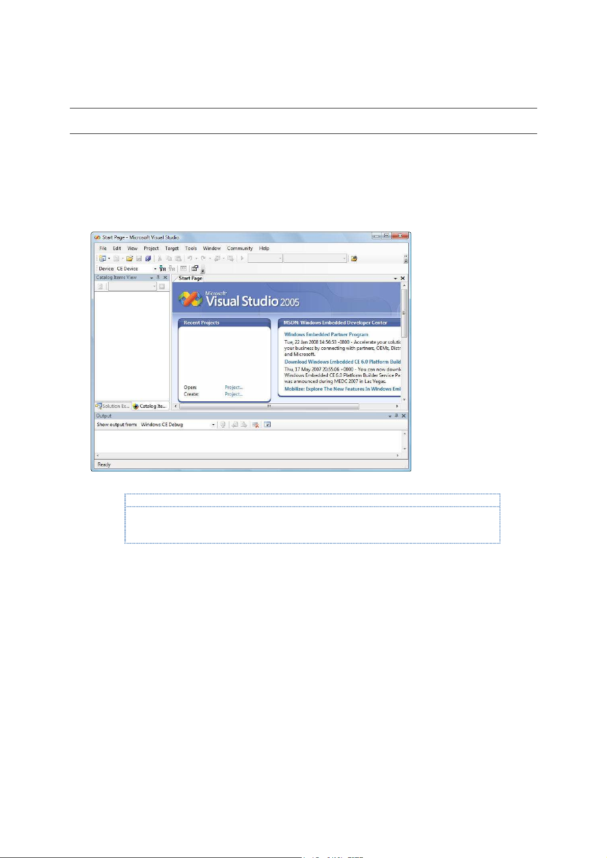
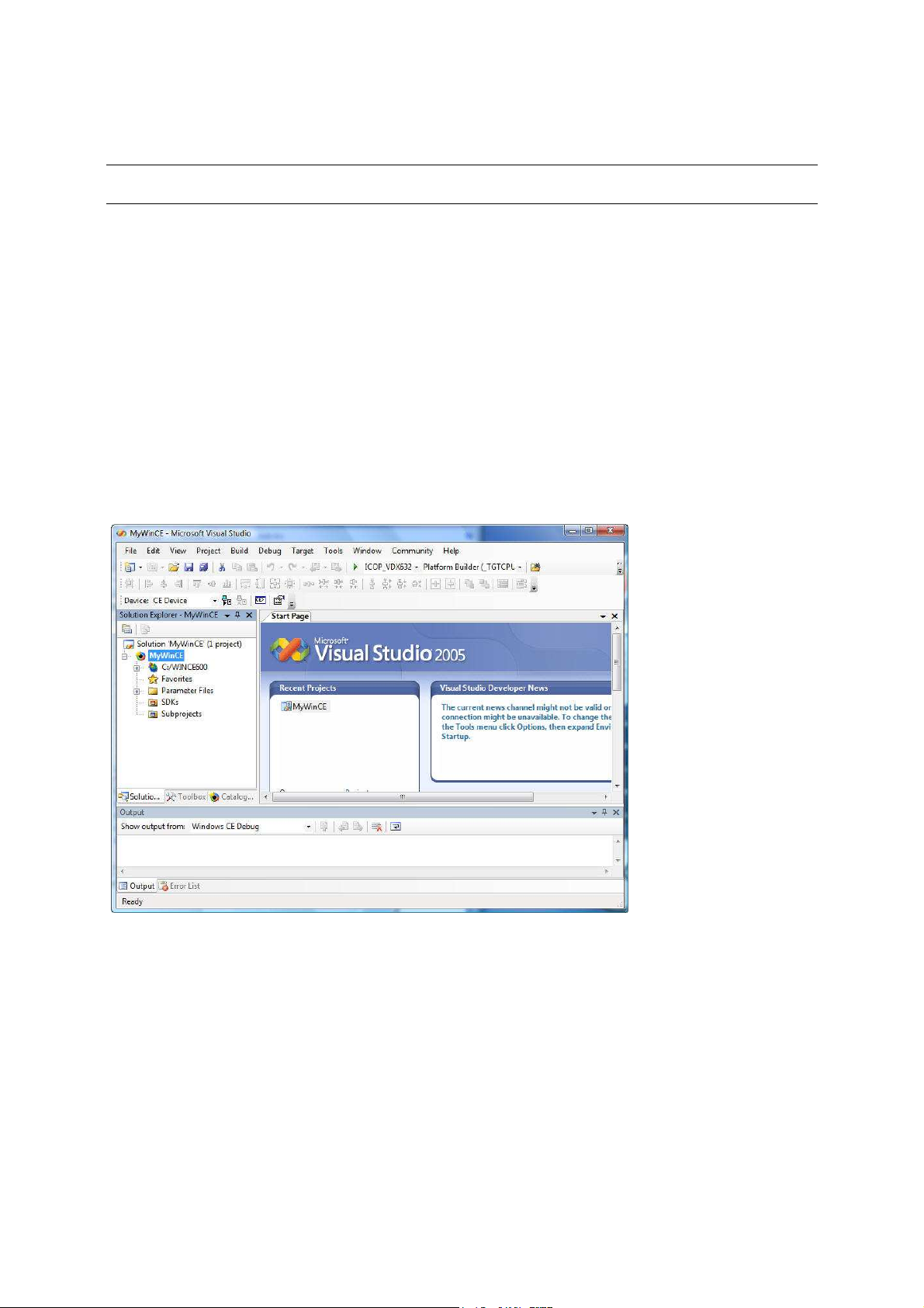
Visual Studio 2005
This exercise starts from the VS2005 IDE. To begin, launch VS2005. After launching, the VS2005 IDE
screen is shown, similar to the one as shown in Figure 6.
Fig. 6 - VS2005 IDE
To make it easier for capturing the Visual Studio IDE screen and create documentation for this
getting started guide, the Visual Studio IDE is resized to 800x600 and may have different looks and
feel from the VS2005 IDE, launch in full screen mode with 1024x768 and higher display resolution.
The VS2005 IDE provides support to create different type of projects, such as Windows Application,
Console Application, Class Library, smart device application, Windows Services, Web Control, etc…
When starting a new project with VS2005, the VS2005 IDE provides wizards and templates to help
create the initial set of files for the project. Platform Builder for CE 6.0 is one of the available project
types. From the VS2005 IDE, select “File | New | Project …” to bring up the new project screen, as
shown in Figure 7.
Vortex86DX-MSJK Windows Embedded CE 6.0 R3 Jump Start Rev 2.2
Page 22 of 144
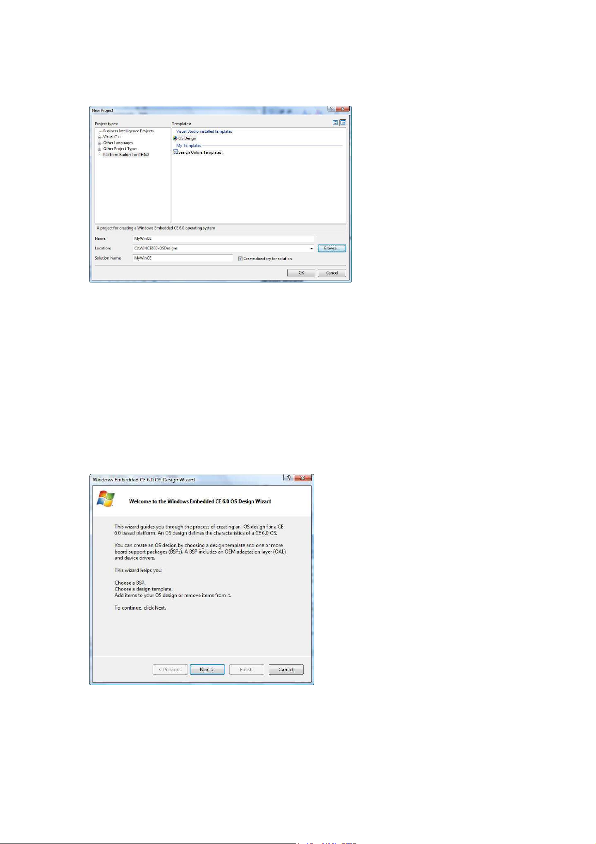
Fig. 7 - VS2005 New Project – CE 6.0 OS design
•
From the New Project screen’s left pane, click to highlight the Platform Builder for CE 6.0
option.
•
From the right pane, click to high-light the OS Design option.
•
Enter MyWinCE as the name of the OS design project.
•
Make sure the Create directory for solution check box is checked.
•
Click on the OK button to continue.
Windows Embedded CE 6.0 OS Design Wizard
When a new CE 6.0 OS design project is selected, the VS2005 IDE launches the Windows Embedded
CE 6.0 OS Design Wizard and steps through the process to configure the initial OS design project, as
shown in Figure 8.
Fig. 8 - Windows Embedded CE 6.0 OS design Wizard
•
Click on the Next button to continue and bring up the Board Support Packages selection
screen.
Vortex86DX-MSJK Windows Embedded CE 6.0 R3 Jump Start Rev 2.2
Page 23 of 144
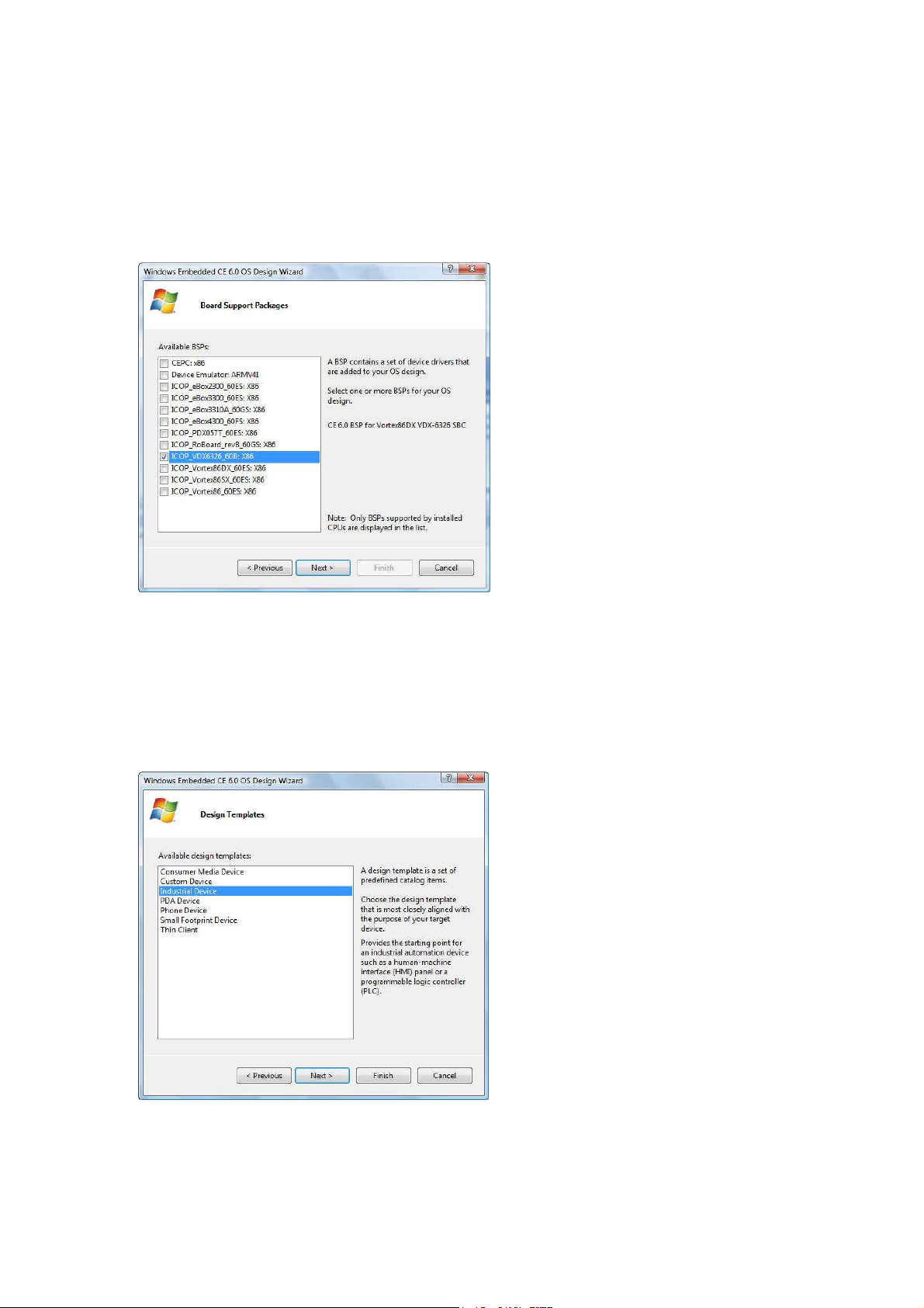
OS Design Wizard – Board Support Packages (BSPs)
In the BSP selection step, the OS Design Wizard provides the option to select one or more BSP for
the new OS design project, from the list of available BSP. All of the installed BSPs, including BSPs
from third party companies are listed, as shown in Figure 9.
Fig. 9 - OS design Wizard – Select BSP
•
From the Available BSPs pane, select ICOP_VDX6326_60B: x86 BSP.
•
Click on the Next button to continue, and bring up the Design Templates selection screen.
OS Design Wizard – Design Templates
In the Design Templates selection step, the OS Design Wizard provides the list containing multiple
design templates to choose from, as shown in Figure 10.
Fig. 10 - OS design Wizard – Design Templates
Vortex86DX-MSJK Windows Embedded CE 6.0 R3 Jump Start Rev 2.2
Page 24 of 144
•
Select the Industrial Device option from the list of available design templates.
•
Click on the Next button to continue and bring up the Design Template Variants selection
screen, as shown in Figure 11.
Fig. 11 - OS design Wizard – Design Template Variants
•
From the Design Template Variants screen, select the Internet Appliance option.
•
Continue and click on the Next button to bring up the Application & Media selection screen.
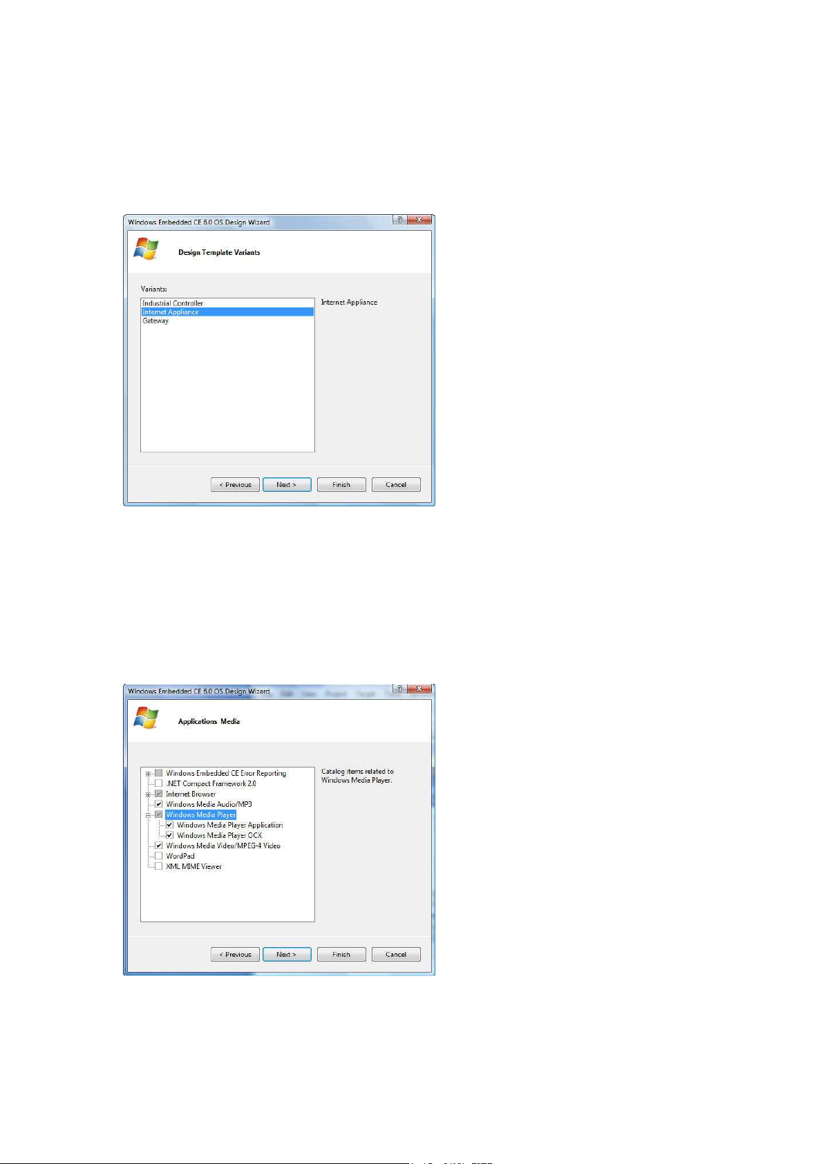
OS Design Wizard – Applications & Media
In the applications & media selection step, the OS Design Wizard provides the option to select .NET
Compact Framework to support managed code application, Internet Explorer, Windows Media
components, and etc., as shown in Figure 12.
Fig. 12 - OS design Wizard – Applications & Media
Vortex86DX-MSJK Windows Embedded CE 6.0 R3 Jump Start Rev 2.2
Page 25 of 144
For this step, perform the following:
Note:
•
Uncheck the .NET Compact Framework 2.0 to remove from the selection.
(In a later step, we will include a newer version, .NET Compact Framework 3.5, to support managed
code application.)
•
Select the Internet Explorer 6.0 component.
•
Select the Windows Media Audio/MP3 component.
•
Select the Windows Media Player Application component.
•
Select the Windows Media Player OCX component.
•
Select the Windows Media Video/MPEG-4 Video component.
•
Click on the Next button to continue, and bring up the Networking & Communication
selection screen.
.NET Compact Framework is needed to support managed code application. In this step, the .NET
Compact Framework 2.0 library is excluded. In the later step, we will add the newer version, .NET
Compact Framework 3.5, to the OS design project.
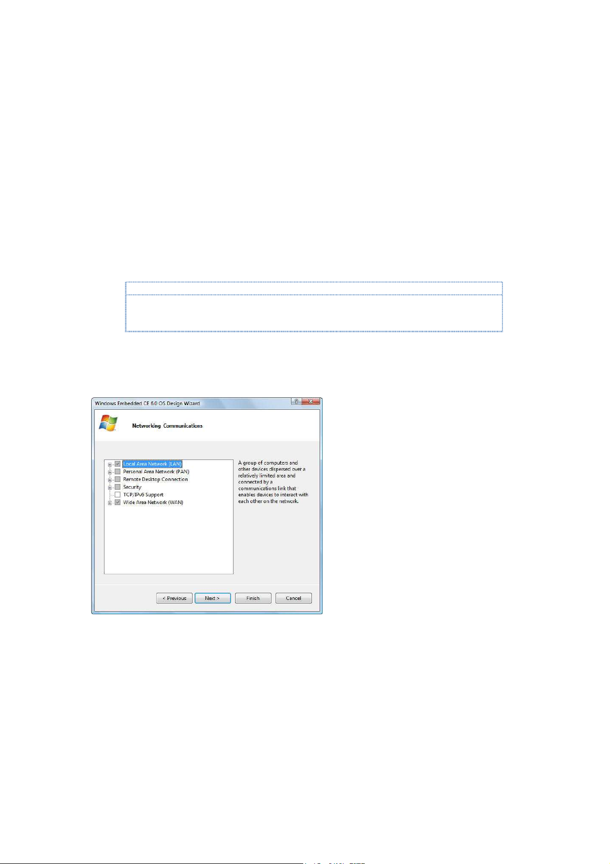
OS Design Wizard – Networking & Communications
In the networking & communications step, the OS Design Wizard provides the options to select
communication, networking and security components, as shown in Figure 13.
Fig. 13 - OS design Wizard – Networking & Communications
For this step, we will use the default settings for networking and communications. Click on the Next
button to continue.
At this point, the OS Design Wizard collected the necessary OS design parameters needed to
configure the initial OS design project, based on the selected template and components.
Vortex86DX-MSJK Windows Embedded CE 6.0 R3 Jump Start Rev 2.2
Page 26 of 144

Fig. 14 - OS design Wizard – Completed
•
From the final OS design wizard screen, click on the Finish button to complete the OS Design
Wizard step.
Security Warning - Catalog Item Notification
At the completion of OS Design Wizard, a security warning is raised to warn one or more of the
selected components for the OS design may pose security risk, as shown in Figure 15.
Fig. 15 - Catalog Item Notification – Security Warning
Click on the Acknowledge button to close the warning screen.
At the completion of the OS design wizard, Platform Builder generates the initial OS design project
files and pulls in all required files associate with the OS design template and selected components,
to the following directory:
•
C:\WINCE600\OSDesigns\MyWinCE\
Vortex86DX-MSJK Windows Embedded CE 6.0 R3 Jump Start Rev 2.2
Page 27 of 144
Part 5 –
In this section, we will work through the steps to configure and customize the OS design project.
At this point, with help from the OS design Wizard, the initial MyWinCE project is created using the
Internet Appliance design template along with the ICOP_VDX6326_60B BSP and selected components.
The following project folder and sub-folders are created for the OS design, under the main CE 6.0 OS
design project directory, C:\WINCE600\OSDesigns:
•
C:\WINCE600\OSDesigns\MyWinCE\
This is the folder for the MyWinCE Solution. VS2005 supports different project types. A solution provides
a centralized work space to keep different project types supporting the same solution in one location.
For example, the MyWinCE solution may include the “MyWinCE OS design”, “Visual Basic managed code
application”, “Visual C# managed code application” and “Visual C++ native code application”.
•
C:\WINCE600\OSDesigns\ MyWinCE\MyWinCE\
This is the folder for the MyWinCE OS design project.
Your VS2005 IDE should look similar to the screen as shown in Figure 16.
Configure and Customize CE 6.0 OS Design
Fig. 16 - VS2005 IDE after OS design Wizard
Customize the OS Design – Add Additional Components
The OS design can be further customized with the following:
•
Add component(s) to the OS design.
•
Remove component(s) from the OS design.
•
Add application and library as subproject to the OS design.
•
Modify system configuration and registry files to control system behavior.
Vortex86DX-MSJK Windows Embedded CE 6.0 R3 Jump Start Rev 2.2
Page 28 of 144

With the OS design project active, the Catalog Item View window on the VS2005 IDE lists all of the
Note:
The ICOP_VDX6326_60B
BSP
is a derivative of the ICOP_Vortex86DX_60B BSP
.
Components are
Note:
CE 6.0 components, including applications, library, drivers, utilities & 3rd party components installed
to the development workstation and available to be added to the OS design project.
On the Catalog Item View windows, the green check mark to the left of a component indicates the
component is selected to be part of the OS design. The solid green square to the left of a
component indicates the component is included to the OS design as the result of being a
dependency to another component selected for the OS design.
Work through the following steps to further customize the MyWinCE OS design project:
•
From the VS2005 IDE, click on the Catalog Items View tab, expand the \Third
Party\BSP\ICOP_VDX6326_60B: x86 node, as shown in Figure 13.
Fig. 13 - BSP in CE 6.0 Component Catalog
added or enabled to support features specific to the VDX-6326 SBC.
Verify the following BSP components are selected and included to the OS design:
•
ATAPI PCI Support
The ATAPI PCI Support component set the SYSGEN_ATAPI variable to include the ATAPI storage
driver, and the SYSGEN_FATFS variable to include FAT file system support.
Vortex86DX-MSJK Windows Embedded CE 6.0 R3 Jump Start Rev 2.2
Page 29 of 144

•
Note:
The Hive
-
based registry component is needed to save registry settings to
non volatile flash storage
Note:
The VDX
-
6326 SBC has 3 10/100 Mbps
Ethernet ports onboard. One of the Ethernet port uses the
Note:
The VDX
-
6326 SBC is available with 256MB or 512MB of system memory
. This component set the
Note:
This component set the BSP_SERIAL environment variable to include serial port driver to the OS
Note:
This component set the BSP_SERIAL2 environment variable to include serial port driver to the OS
Note:
This component set the BSP_SERIAL
3 environment variable to include serial port driver t
o the OS
Note:
Th
is component set the BSP_SERIAL4
environment variable to include serial port driver t
o the OS
Note:
The SPI Flash driver supports the 4MB SPI flash built
-
in to the VDX
-
6326 SBC
.
Note:
This component set the SYSGEN_USB, BSP_USB_OHCI, BSP_USB_UHCI and BSP_USB_EHCI
Hive-based registry support
between power reset.
•
R6040 Ethernet driver
R6040 controller which is built-in to the Vortex86DX SoC. The other two Ethernet ports use the
Realtek-8100 controller, which is supported by the Realtek-8139 Ethernet driver.
For this exercise, we only need one Ethernet interface.
•
256MB RAM
IMGRAM256 environment variable and configure the OS runtime image to use the 256MB of
available system memory.
The VDX-6326 SBC for the Vortex86DX-MSJK jump start kit is built with 256MB of system memory.
•
1st Serial Port
runtime to support COM1, the first serial port. By default, the VDX-6326 SBC’s 1st serial port is
configured as follow:
- COM1: IRQ-4, 3F8h
•
2nd Serial Port
runtime to support COM2, the second serial port. By default, the VDX-6326 SBC’s 2nd serial port is
configured as follow:
- COM2: IRQ-3, 2F8h
•
3rd Serial Port
runtime to support COM3, the third serial port. By default, the VDX-6326 SBC’s 3rd serial port is
configured as follow:
- COM3: IRQ-10, 3E8h
•
4th Serial Port
runtime to support COM4, the fourth serial port. By default, the VDX-6326 SBC’s 4th serial port is
configured as follow:
- COM4: IRQ-11, 2E8h
•
SPI Flash driver
•
USB 2.0 Controller driver
environment variables to include the USB 2.0 driver.
Vortex86DX-MSJK Windows Embedded CE 6.0 R3 Jump Start Rev 2.2
Page 30 of 144
 Loading...