

Page 1

Samuel Phung
Windows Embedded MVP
ICOP Technology Inc.
Screen captured with Snagit
VDX-6318
Windows Embedded Compact 7
Getting Started Guide
Page 2

VDX-6318 Windows Embedded Compact 7 - Getting Started Guide
Table of Contents
Introduction .................................................................................................................................................. 6
Part 1 – Development Environment Overview ............................................................................................. 7
Windows Embedded Compact 7 .............................................................................................................. 7
Windows Embedded Compact 7 – Platform Builder ................................................................................ 7
Windows Embedded Compact 7 Remote Tools ....................................................................................... 7
Visual Studio 2008 Integrated Development Environment ...................................................................... 8
Develop Compact 7 Devices: Typical Development Steps ....................................................................... 8
Develop Compact 7 Applications with VS2008......................................................................................... 9
Silverlight for Windows Embedded .......................................................................................................... 9
The Target Device ..................................................................................................................................... 9
Common Terminology ............................................................................................................................ 11
Compact 7 Environment and Directory Variables .................................................................................. 12
OEM Environment Variables .................................................................................................................. 12
Part 2 – Development Environment Connectivity ...................................................................................... 13
Ethernet Connectivity ............................................................................................................................. 13
Develop Compact 7 OS Run-time Image – OS Design .................................................................... 13
Develop Compact 7 Applications with Visual Studio ..................................................................... 13
Serial Debug Connectivity ....................................................................................................................... 13
Development Environment Setup with DHCP ........................................................................................ 14
Using Wireless Access Point Router ....................................................................................................... 14
Development Environment Setup with Static IP .................................................................................... 15
Local Area Network without DHCP Service .................................................................................... 15
Direct Connection using Cross-Over RJ-45 Ethernet Cable............................................................ 15
Static IP Addresses ......................................................................................................................... 15
Part 3 – Required Software & Installation .................................................................................................. 16
Recommended Software Installation Sequence .................................................................................... 16
Windows Embedded Compact 7 Installation ......................................................................................... 16
Board-Support-Package Installation ....................................................................................................... 17
SDK Installation ....................................................................................................................................... 18
AutoLaunch Component Installation ...................................................................................................... 18
CoreCon Connectivity Component ................................................................................................... 18
Part 4 – OS Design (Platform Builder Project) ............................................................................................ 19
Visual Studio 2008 .................................................................................................................................. 19
Windows Embedded Compact 7 OS Design Wizard ............................................................................... 19
Windows Embedded Compact 7 Getting Started Rev 2.00 Page 2
Page 3

VDX-6318 Windows Embedded Compact 7 - Getting Started Guide
OS Design Wizard – Board Support Package (BSP) ................................................................................. 20
OS Design Wizard – Design Templates ................................................................................................... 21
OS Design Wizard – Applications & Media ............................................................................................. 21
OS Design Wizard – Networking & Communications ............................................................................. 22
Security Warning - Catalog Item Notification ......................................................................................... 23
Part 5 – Configure and Customize Compact 7 OS Design ........................................................................... 24
Customize the OS Design – Add Additional Components ...................................................................... 24
Customize the OS Design – Locate Component by Search ..................................................................... 29
Customize the OS Design – Configuration Manager .............................................................................. 30
Customize the OS Design – Build Options .............................................................................................. 31
Customize the OS Design – The Registry ................................................................................................ 32
Registry Entries for FTP Server Component ................................................................................... 32
Registry Entries for the Telnet Server Component ........................................................................ 32
Registry Entries for the AutoLaunch Component .......................................................................... 32
Adding Registry Entries to OS Design ............................................................................................ 33
Static IP Address ..................................................................................................................................... 33
Other Compact 7 Components ............................................................................................................... 34
Part 6 – Build and Generate Compact 7 OS Run-time Image ..................................................................... 35
The Build Process – Starting ................................................................................................................... 35
The Build Process – Completed .............................................................................................................. 35
Part 7 – Download Compact 7 OS Run-time to Target Device .................................................................... 37
Target Device Preparation ...................................................................................................................... 37
Create Connectivity Profile for a Target Device ..................................................................................... 38
Associate VDX-6318 to MyTargetDevice Connectivity Profile ............................................................... 39
Download Compact 7 OS Run-time Image to VDX-6318 ........................................................................ 42
Deploy Compact 7 OS Run-time Image to Target Device ....................................................................... 43
Part 8 – Software Development Kit (SDK) ................................................................................................... 45
Create and Configure Compact 7 SDK .................................................................................................... 45
Build and Generate Compact 7 SDK ....................................................................................................... 47
Part 9 – Develop Native Code App with VS2008......................................................................................... 48
Create a New Native Code Application Project ...................................................................................... 48
Add Codes and Build the Application Project ......................................................................................... 51
Preparing Target Device to Connect to VS2008 IDE ............................................................................... 52
Configure VS2008 Device Connectivity Settings ..................................................................................... 54
Establish Connectivity to Compact 7 Target Device ............................................................................... 56
Windows Embedded Compact 7 Getting Started Rev 2.00 Page 3
Page 4

VDX-6318 Windows Embedded Compact 7 - Getting Started Guide
Download Application to Target Device ................................................................................................. 57
Part 10 – Develop Managed Code App with VS2008 .................................................................................. 58
Create a New Managed Code Application Project ................................................................................. 58
Add Codes and Build the Application Project ......................................................................................... 60
Preparing Target Device to Connect to VS2008 IDE ............................................................................... 61
Establish Connectivity to Compact 7 Target Device ............................................................................... 61
Download Application to Target Device ................................................................................................. 62
Debug Application Running on Target Device ........................................................................................ 64
Part 11 – Debug and Remote Tools ............................................................................................................ 67
Download KITL Enabled Compact 7 OS Image to Target Device ............................................................ 68
Remote Tool: Process Viewer ................................................................................................................ 68
Remote Tool: Registry Editor ................................................................................................................. 70
Remote Tool: System Information ......................................................................................................... 71
Part 12 – Silverlight for Windows Embedded ............................................................................................. 73
Congratulations! – You’ve completed all the steps .................................................................................... 74
Appendix A – Development station Setup with DHCP ................................................................................ 75
Connecting to Local Area Network with DHCP ....................................................................................... 75
Using Wireless Access Point Router ....................................................................................................... 75
Capturing Serial Debug Messages .......................................................................................................... 76
Appendix B – Development station Setup with Static IP ............................................................................ 77
Connecting to Ethernet Hub or Switch without DHCP ........................................................................... 77
Direct Connection with Cross-Over RJ-45 Ethernet Cable ...................................................................... 77
Static IP Address ..................................................................................................................................... 77
Capturing Serial Debug Messages .......................................................................................................... 78
Appendix C – Windows Embedded Compact Resources ............................................................................ 79
Appendix D – VDX-6318-MSJK Technical Information ................................................................................ 82
Appendix E – Startup Options ..................................................................................................................... 91
Configure the SBC to boot from USB Flash Storage ............................................................................... 91
Appendix F – BIOSLoader ............................................................................................................................ 92
Primary BIN File .................................................................................................................................. 92
Alternative BIN File ............................................................................................................................ 92
BIOSLoader Configuration File for VDX-6318 ............................................................................... 93
Appendix G – Using Static IP Address ......................................................................................................... 95
Configure Static IP for Prebuilt Compact 7 OS Run-time ........................................................................ 95
Configure OS Design with Static IP Address ........................................................................................... 96
Windows Embedded Compact 7 Getting Started Rev 2.00 Page 4
Page 5

VDX-6318 Windows Embedded Compact 7 - Getting Started Guide
Appendix H – Deploy OS Run-time with DiskPrep ...................................................................................... 97
Appendix I – CoreCon Connectivity .......................................................................................................... 100
Appendix J – Recover Jump Start Kit’s Original Files ................................................................................ 102
VDX-6318-MSJK Preconfigured Files .................................................................................................... 102
Recover Files with DiskPrep .................................................................................................................. 102
Appendix K – VDX-6318 System BIOS ....................................................................................................... 104
Appendix L – Using Watchdog Timer ........................................................................................................ 106
Using WDT0 .......................................................................................................................................... 106
Using WDT1 .......................................................................................................................................... 108
Watchdog Timer DLL: WDT.dll ............................................................................................................. 109
Appendix M – Using GPIO ......................................................................................................................... 110
Using the GPIO ...................................................................................................................................... 110
Windows Embedded CE Sample Codes ....................................................................................... 110
Configure GPIO to Output Mode ................................................................................................. 111
Configure GPIO to Input Mode .................................................................................................... 112
GPIO.DLL ...................................................................................................................................... 113
Windows Embedded Compact 7 Getting Started Rev 2.00 Page 5
Page 6

VDX-6318 Windows Embedded Compact 7 - Getting Started Guide
Introduction
This Windows Embedded Compact 7 (Compact 7) getting started guide, with hands-on exercises, is
written in step-by-step format to show how to create a Compact 7 OS design, build customized OS runtime image from the OS design, configure the development environment to download the OS run-time
image to a target device, develop Compact 7 applications using the Visual Studio 2008 (VS2008)
Integrated Development Environment (IDE).
The following subjects are covered in this guide:
Development environment overview
Required software and recommended installation sequences
Develop and configure Compact 7 OS design project
Build customized Compact 7 OS run-time image
Establish connectivity and download OS run-time image to target device
Develop VS2008 managed and native code application for Compact 7 device
Develop managed and native code applications for Compact 7 using Visual Studio 2008,
establish connectivity and download the application to target device for testing and debugging
Using Kernel Independent Transport Layer (KITL) and Remote Tools to debug Compact 7 OS run-
time on a target device
While it’s possible to use a Virtual PC as the target device and work through similar exercises, using a
real hardware provides a practical environment, and helps improve the learning process. The VDX-6318
Single-Board-Computer (SBC), configured with the necessary software components, is used as the target
device for the exercises in this guide.
To minimize unnecessary problem caused by missing software components and improper development
environment setup, follow the recommended software installation sequences and setup provided as
part of this getting started guide to install the necessary software.
The primary objective for this guide is to show how to use Compact 7 development tools. It’s not within
this guide’s objective to talk about programming language and concept. Short and simple exercises are
used in this guide to keep the subject matter simple and easy to understand.
Update to this getting started guide and other Compact 7 resources are available from the following
URLs:
http://www.embeddedpc.net/VDX6318MSJK/
http://www.embeddedpc.net/download/VDX6318.htm
Windows Embedded Compact 7 Getting Started Rev 2.00 Page 6
Page 7

VDX-6318 Windows Embedded Compact 7 - Getting Started Guide
Note:
The previous version, Windows Embedded CE 6.0 Platform Builder, is a plug-in to the Visual Studio
2005 IDE.
For Windows CE 5.0 and earlier versions, Platform Builder was a standalone development tool.
Part 1 – Development Environment Overview
The Windows Embedded Compact 7 Platform Builder (Platform Builder) development tool is a plug-in to
the Visual Studio 2008 integrated development environment (VS2008 IDE). All Compact 7 development
tasks are supported within the VS2008 IDE, a developer friendly, efficient and intuitive development
environment with templates and wizard to help simplify complicate development tasks.
Windows Embedded Compact 7
Windows Embedded Compact 7 is a hard Real-time operating system with ability to handle 32,000
concurrent processes and 2GB memory footprint for each process. Compact 7 delivers reliable,
secure performance in a small footprint package along with the latest networking, multimedia and
communications technologies. Compact 7 provides broad range of device support with enhanced
features, including robust file system, Web services for device, Silverlight for Windows Embedded,
voice over IP, network gateway configurations, platform development tool enhancements, greater
application compatibility with other Windows Embedded Compact based devices, Internet Explorer,
Windows Media CODECs, Microsoft .NET Compact Framework, and a number of other newly
supported protocols and services.
Combining large pool of production quality BSPs, device drivers, programming libraries and effective
development tools, Compact 7 provides an ideal rapid application development environment to help
create the next generation of smart, media rich, connected and service oriented devices. For more
information about Compact 7, visit:
http://www.microsoft.com/windowsembedded/en-us/products/windowsce/compact7.mspx
Windows Embedded Compact 7 – Platform Builder
Platform Builder is the development tool used to create Compact 7 OS design projects, build custom
Compact 7 OS run-time images and develop Compact 7 device drivers. It also provides the remote
tools to debug Compact 7 OS run-time image, device drivers and software components on a target
device.
Platform Builder for Compact 7 is a plug-in to the VS2008 IDE, and requires the VS2008 IDE to
function.
Windows Embedded Compact 7 Remote Tools
Using remote tools provided as part of the Compact 7 development environment, you are able to
remotely debug Compact 7 OS run-time image running on a target device, built with KITL enabled.
The following remote tools are provided as part of the Compact 7 development environment:
File Viewer
Kernel Tracker
Performance Monitor
Power Monitor
Windows Embedded Compact 7 Getting Started Rev 2.00 Page 7
Page 8

VDX-6318 Windows Embedded Compact 7 - Getting Started Guide
Process Viewer
Profiler
Registry Editor
Resource Consumer
Resource Leak Detector
System Information
Timeline Viewer
Zoom
Visual Studio 2008 Integrated Development Environment
Visual Studio 2008 is a popular developer friendly development tool to develop broad range of
applications for different version of the Windows operating system. From the VS2008 IDE, you can
develop applications for the following Windows operating system:
Windows 7 and Windows Embedded Standard 7
Windows Vista, Windows XP and Windows XP Embedded
Windows 2003 and 2008 Server
Windows Phone 7, Windows Mobile Smartphones and Windows Embedded Handheld
devices
Windows Embedded CE 6.0 and Windows Embedded Compact 7 devices
More…
The VS2008 IDE provides a centralized development environment to develop broad range of
applications, such as:
Windows Form application
Win32, ATL and MFC project
DLL, ActiveX control, ASP.NET Web service, Windows service
SQL Server project, Console application, Class libraries
Windows Embedded Compact and Mobile Smart Device application
Windows Embedded Compact OS design
More…
Develop Compact 7 Devices: Typical Development Steps
After the hardware platform is selected, a typical Compact 7 device development project goes
through the following development phases:
Develop Compact 7 bootloader, device drivers and BSP for the selected hardware (some
hardware vendors provide device driver and BSP to support their hardware)
Create and customize an OS design project for the hardware
Build customized Compact 7 OS run-time image for the hardware
Deploy Compact 7 OS run-time image to the hardware for testing and debugging
Generate Compact 7 SDK from the OS design to support application development
Develop application for the Compact 7 device
Windows Embedded Compact 7 Getting Started Rev 2.00 Page 8
Page 9

VDX-6318 Windows Embedded Compact 7 - Getting Started Guide
Application development can take place concurrently, as the hardware and OS design being
fine-tuned
After the satisfied Compact 7 OS run-time image and application are created, deploy the
solution to the final hardware for distribution
Develop Compact 7 Applications with VS2008
Visual Studio 2008 supports application development for Compact 7 devices. There are multiple
options to develop Compact 7 applications using the VS2008 IDE:
Develop Native code application with Visual C++
Develop Managed code application with Visual C#
Develop Managed code application with Visual Basic
A Software Development Kit (SDK), generate from the OS design for the target device, is needed to
support native code application development for the target device using VS2008.
The Visual Studio IDE provides an efficient development environment, making it possible to
download the OS run-time image and application from the development station to the target device
for testing and debugging.
From the Visual Studio 2008 IDE with KITL and CoreCon connectivity, you are able to download OS
run-time image and application to a Compact 7 target device, launche the application, set
breakpoint and step through the codes one-line-at-a-time as the application runs on the target
device.
Silverlight for Windows Embedded
Silverlight is a user interface (UI) development framework designed to separate the graphical
presentation from the programming logic. Silverlight enables graphic designer to design the
graphical presentation for the application without the need to understanding the programming logic
and provides a structured system for the application developer and graphic designer to work
together, doing what they do best.
While the desktop and Windows Phone 7 Silverlight application’s code behind is based on managed
code, Silverlight for Windows Embedded application’s code behind is based on native code, which
provides an environment to develop small and efficient code to support embedded devices typically
built with limited hardware resources.
Silverlight for Windows Embedded enables UI designers to develop stunning UI for the device
without the need to understand complicated application code. At the same time, application
developer can focus on their core expertise, develop the application logic and leverage UI graphic
designer’s expertise to design user interface for the project.
Silverlight for Windows Embedded application for Compact 7 is developed using the combination of
C++ and XAML code, using Visual Studio 2008 and Expression Blend 3.
The Target Device
The term target device is referring to the hardware platform used in a Compact 7 development
project. For the exercises in this guide, the VDX-6318 single-board-computer (SBC) is used as the
target device.
Windows Embedded Compact 7 Getting Started Rev 2.00 Page 9
Page 10
VDX-6318 Windows Embedded Compact 7 - Getting Started Guide
Note:
We will refer to the VDX-6318 SBC as “SBC” or “Target Device” within this getting started guide.
A VDX-6318 BSP which includes the necessary hardware adaptation codes, device drivers and
configuration files to support Compact 7 OS development, is used for the exercises in this guide to
develop the OS design project, as shown in Figure 1.
Fig. 1 – ICOP_VDX6318_70B BSP for Compact 7
In addition to the device drivers, the following DLLs are included as part of the BSP to help
developers access the SBC’s GPIOs and Watchdog timers:
GPIO.dll (To access the GPIOs)
WDT.dll (To access the Watchdog timers)
When developing an OS design using the ICOP_VDX6318_70B BSP, these DLLs are included to the OS
design and compile into the OS run-time image by default.
Sample native and managed code projects showing how to use these DLLs are provided on the jump
start CD-ROM.
Refer to appendix L for more information about watchdog timer.
Refer to appendix M for more information about GPIO.
Windows Embedded Compact 7 Getting Started Rev 2.00 Page 10
Page 11

VDX-6318 Windows Embedded Compact 7 - Getting Started Guide
Abbreviation/ key word
Description and Representation
Compact 7
Windows Embedded Compact 7
Platform Builder
Windows Embedded Compact 7 Platform Builder
VS2008
Visual Studio 2008
IDE
Integrated Development Environment
BSP
Board Support Package: A group of Windows Embedded Compact
software components that includes the OEM adaptation layer code,
device drivers and configuration files, needed to create the OS design
project to generate OS run-time image for the targeted hardware.
OAL
OEM Adaptation Layer
Component
Component can be a device driver, BSP, programming library,
application, utility, configuration settings, fonts, etc... The OS design is
made up by a group of components.
Component Catalog
The component catalog lists all of the components provided by Platform
Builder and installed 3rd party components. The component catalog
provides the interface to add components to the OS design project and
remove components from the project. This is also the interface to view
which components are included to the OS design project.
OS Design
OS design is a Platform Builder project, containing components that
make up the OS run-time image. Windows Embedded Compact OS runtime image is generated from an OS design project.
Target Device
Refer to the device used in the Compact 7 development environment.
When working on exercise using an emulator, the emulator is the target
device. Virtual PC can also be a target device for the Compact 7
development environment. For the exercise in this guide, the VDX-6318
SBC is the target device.
OS Run-time Image
The binary file generated from the OS design project to deploy to the
target device.
Release Directory or
Build Release Directory
Referring to the directory where all files related to the OS design
projects are placed by the build tools prior to compiling the OS run-time
image.
SBC
Single-Board-Computer
Common Terminology
To minimize the need to write long description and the need to use lengthy term repeatedly, it’s a
common practice for developer in different industries to use abbreviated key words. To the new
comer, without knowing the terminologies used and what the abbreviated key words represent can
cause confusion.
The following table contains abbreviation for some of the common key words used in the Compact 7
development environment and this getting started guide:
Windows Embedded Compact 7 Getting Started Rev 2.00 Page 11
Page 12
VDX-6318 Windows Embedded Compact 7 - Getting Started Guide
Variable Name
Description - Purpose
BSP_DISPLAY_NOP
Configure the OS design to include the stub display driver
(DDI_NOP.dll) to support headless device.
BSP_NOAUDIO
Configure the OS design to exclude all audio components from the
build.
IMGRAM256
Configure the OS design to generate run-time image supporting
256MB of RAM
PRJ_ENABLE_FSREGHIVE
Configure the OS design to enable Hive-based registry support
_WINCEROOT
Defines the root directory for the Compact 7 install, default is:
C:\WINCE700
_PLATFORMROOT
Represent the following directory:
$(_WINCEROOT)\PLATFORM
Or
C:\WINCE700\PLATFORM
Variable Name
Description - Purpose
BSP_VORTEX86DX_IDE
Enable support for IDE storage device.
BSP_VORTEX86DX_9120A
Enable support for IDE device built with 9120A chip.
BSP_NIC_R6040
Enable support for R6040 Ethernet controller.
BSP_DISPLAY_Z9S_xxxx
Multiple environment variables to configure display settings.
BSP_VDX_DisableAgressiveFlush
When enabled, it configures the OS design to disable aggressive
registry flushing.
Compact 7 Environment and Directory Variables
Within the Compact 7 development environment, environment variables are used to configure the
OS design to include, exclude associated components and control certain system behaviors.
Directory variables representing the associated directory are used to help make the codes and script
easier to understand and read. Here are some of these variables:
The above table lists a small sampling of variables used in the Compact 7 development environment.
For more information about these environment variables, visit the following URLs:
About Environment Variables:
http://msdn.microsoft.com/en-us/library/gg154986.aspx
BSP Environment Variables:
http://msdn.microsoft.com/en-us/library/ee478674.aspx
IMG Environment Variables:
http://msdn.microsoft.com/en-us/library/ee479025.aspx
PRJ Environment Variables:
http://msdn.microsoft.com/en-us/library/ee479112.aspx
Miscellaneous Environment Variables:
http://msdn.microsoft.com/en-us/library/ee479008.aspx
OEM Environment Variables
In addition to the environment variables established by Microsoft, hardware manufacture can
establish environment variables unique to their BSP to support the intended target device. The
following environment variables are unique to the ICOP_VDX6318_70B BSP:
Windows Embedded Compact 7 Getting Started Rev 2.00 Page 12
Page 13

VDX-6318 Windows Embedded Compact 7 - Getting Started Guide
Part 2 – Development Environment Connectivity
It’s important to establish a proper development environment and understand different options
available to establish connectivity between the development station and the target device, to download
OS run-time image, and deploy application to the target device for testing and debug. This section talks
about connectivity between the development station and the target device.
Ethernet Connectivity
For the exercises in this guide, Ethernet is the primary connectivity used in the development
environment with both the development station and target device connected to the same Local
Area Network (LAN).
Ethernet connectivity is used to download the OS run-time image from the development station to
the target device and deploy application to the target device for testing and debugging.
Develop Compact 7 OS Run-time Image – OS Design
Compact 7 OS design is one of the project type supported by the VS2008 IDE, to generate
custom OS run-time Image.
As part of the OS design development process, connectivity between the development station
and target device is needed to download OS run-time image to the target device. While it’s
possible to use the serial port and other connectivity, Ethernet connection is efficient and
provides the bandwidth to download Compact 7 OS run-time image quickly. Comparing to a
serial connection, where the transfer rate is in the hundred kilo-byte (KB) range, Ethernet
connection’s transfer rate is in the mega-byte (MB) range.
Develop Compact 7 Applications with Visual Studio
The VS2008 IDE supports Compact 7 managed and native code applications development and
provides the environment to deploy application from the development station to the target
device.
As part of the application development exercises in this guide, with CoreCon connectivity
established over an Ethernet connection, the VS2008 IDE provides the facility to deploy
application to the target device, set breakpoint and enables the developer to step through the
code, line by line, as the application executes on the target device.
Serial Debug Connectivity
Serial Debug connectivity is established by connecting a null RS-232 serial modem cable between a
serial port on the target device and an available serial port on the development station. Serial
connection is useful for debugging headless device and the device’s startup process during the
bootloader phase where the Compact 7 OS run-time has not been fully launched.
A terminal emulation program, such as Hyper-Terminal or similar application, running on the
development station, is used to capture serial debug messages from the target device.
Windows Embedded Compact 7 Getting Started Rev 2.00 Page 13
Page 14
VDX-6318 Windows Embedded Compact 7 - Getting Started Guide
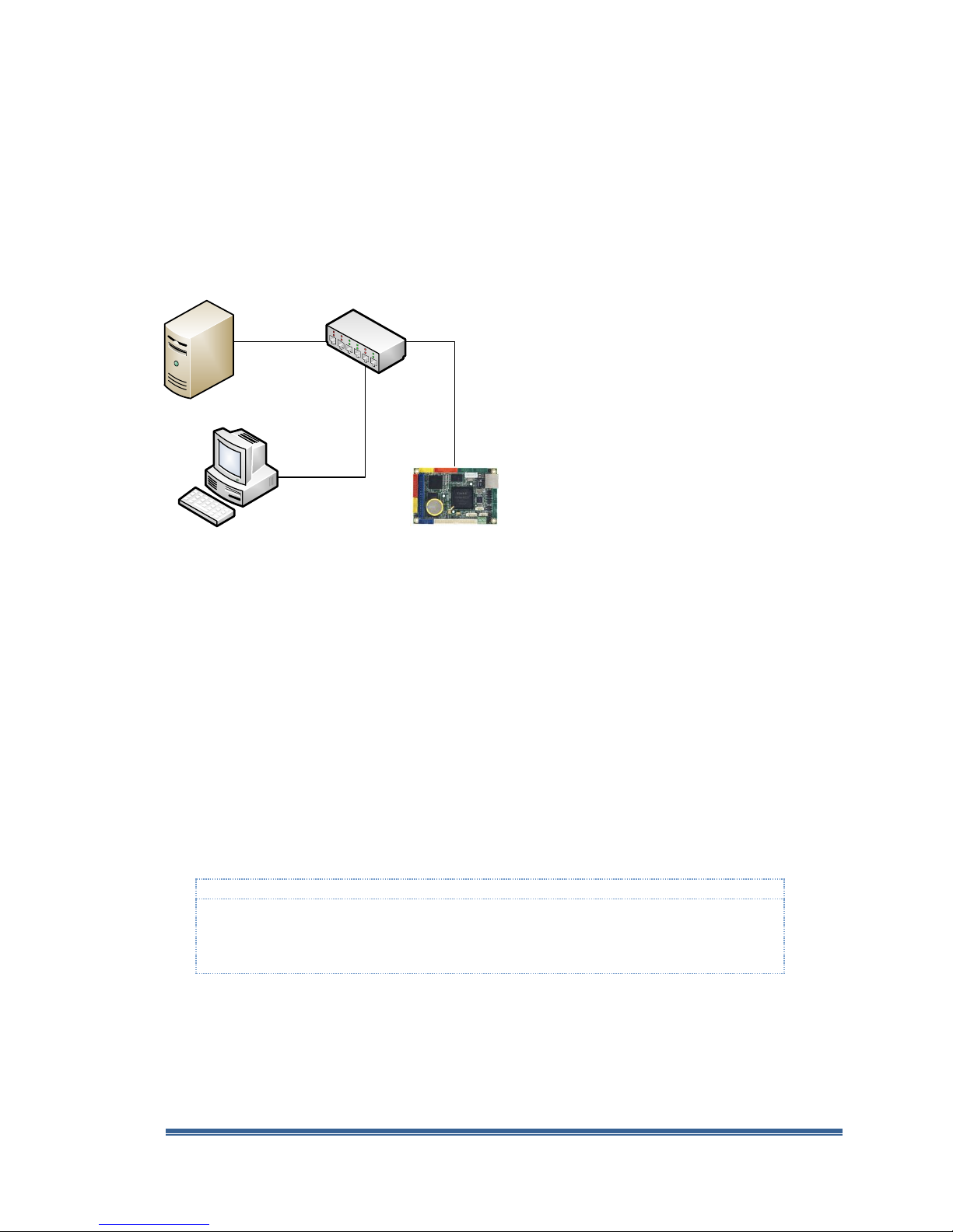
Development Workstation
Ethernet Hub
Server with DHCP
Target Device
Note:
The wireless-access-point-router device’s routing function filter and route network packets based
on the packet’s associated origin, destination and other information. In some router, the routing
algorithm may prevent some of the packets between the development station and target device
from reaching its destination and cause problem.
Development Environment Setup with DHCP
One of the common development environments to support Compact 7 development is to attach
both the development station and target device to the same LAN with DHCP service to provide IP
addresses dynamically with a null RS-232 serial modem cable connected between one of the serial
port on the target device and an available serial port on the development station.
Here is a typical setup to connect both the development station and target device to a LAN with
DHCP service, as shown in Figure 2.
Fig. 2 - Development environment with DHCP service provider
If the target device fails to establish connectivity with the development station as expected with this
configuration, it may be caused by one of the following:
The development station’s firewall software may be blocking the connection
DHCP service for the target device needs to be enabled on your network. Some secured
network may require the target device’s MAC address to be added to the authorized device
list to be serviced by the DHCP server
Using Wireless Access Point Router
When using a wireless-access-point-router with multiple Ethernet ports, connecting both the
development station and target device directly to the Ethernet port on the wireless-access-pointrouter may be problematic with certain model of access point, and prevent the development
environment from functioning as expected.
To minimize connectivity problem, instead of connecting directly to the wireless-access-point-router
device’s Ethernet ports, attach an Ethernet network hub to the wireless-access-point-router device,
to access the DHCP service provided by the wireless-access-point-router, connect both the
development station and target device to the Ethernet network hub. With both the development
station and target device connecting to the same Ethernet hub, the network traffics between them
are not filtered.
Windows Embedded Compact 7 Getting Started Rev 2.00 Page 14
Page 15
VDX-6318 Windows Embedded Compact 7 - Getting Started Guide
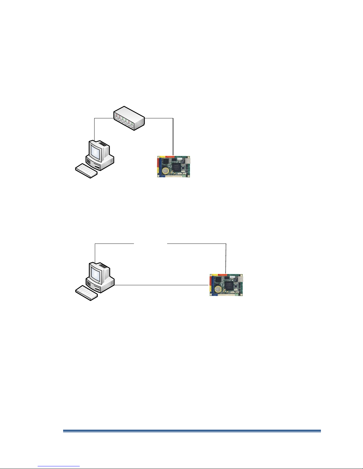
Development Workstation
Ethernet Hub
Target Device
Development Workstation
Null RS-232
Serial Modem Cable
Cross over RJ-45
Ethernet cable
Target Device
Development Environment Setup with Static IP
It’s possible to establish a Compact 7 development environment with Static IP addresses. Here are
two scenarios for setting up the development environment using static IP addresses:
Local Area Network without DHCP Service
The development station and target device are connected to the same LAN or Ethernet Hub,
without DHCP service, as shown in Figure 3.
Fig. 3 - Local Area Network without DHCP
Direct Connection using Cross-Over RJ-45 Ethernet Cable
Connectivity can be established by attaching the target device to the development station
directly, using a cross-over RJ-45 Ethernet cable, as shown in Figure 4.
Fig. 4 - Direct connection with cross-over RJ-45 Ethernet cable
Static IP Addresses
Without DHCP service to assign IP addresses dynamically, the target device and development
station must be configured with appropriate static IP addresses in order to establish
connectivity. Both the development station and target device must be configured with static IP
addresses within the same subnet.
Refer to appendix G for more information about using static IP addresses.
Windows Embedded Compact 7 Getting Started Rev 2.00 Page 15
Page 16

VDX-6318 Windows Embedded Compact 7 - Getting Started Guide
Part 3 – Required Software & Installation
The following software components are needed to work through the exercises in this getting started
guide:
Visual Studio 2008
Visual Studio 2008 service pack 1
Windows Embedded Compact 7
Visual Studio 2008 update for Windows Embedded Compact 7
ICOP_VDX6318_70B BSP
Vortex86DX_SDK_Compact7.msi
AutoLaunch_v300_Compact7.msi
Recommended Software Installation Sequence
It’s important to install the software in their proper sequences. Here is the recommended software
installation sequence:
Visual Studio 2008
Visual Studio 2008 service pack 1
Visual Studio 2008 service pack 1 is available from the following URL:
http://www.microsoft.com/downloads/en/details.aspx?FamilyID=fbee1648-7106-44a7-9649-6d9f6d58056e
Windows Embedded Compact 7
A 180 days evaluation version of Compact 7 software is available for download from
Microsoft, at the following URL:
http://www.microsoft.com/windowsembedded/en-us/downloads/download-windows-embeddedcompact-ce.aspx
Visual Studio 2008 update for Windows Embedded Compact 7
VS2008 update for Compact 7 is available for download from Microsoft, at the following
URL:
http://www.microsoft.com/download/en/details.aspx?id=11935
ICOP_VDX6318_70B_BSP.msi
This BSP is provided on the jump start kit CD, in the \WinCE700 folder.
Vortex86DX_SDK_Compact7.msi
This SDK is provided on the jump start kit CD, in the \WinCE700 folder.
AutoLaunch_v300_Compact7.msi
This AutoLaunch component is provided on the jump start kit CD, in the \WinCE700 folder.
RegFlush_v300_Compact7.msi
This RegFlush component is provided on the jump start kit CD, in the \WinCE700 folder.
Windows Embedded Compact 7 Installation
Since the Compact 7 development tool, Platform Builder, is a plug-in to the VS2008 IDE,
VS2008 must be installed to the develop workstation prior to installing the Compact 7 software.
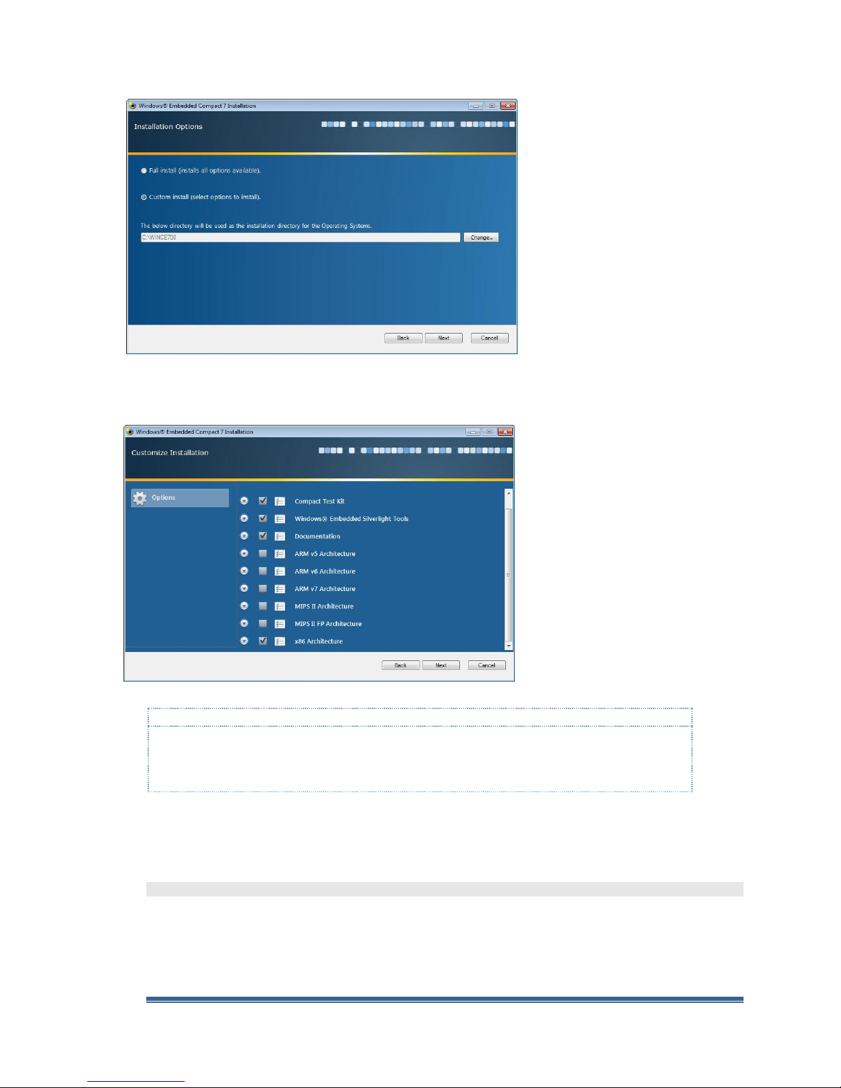
When installing the Compact 7 software, during the installation options selection, select the Custom
install option, as shown in figure 5.
Windows Embedded Compact 7 Getting Started Rev 2.00 Page 16
Page 17
VDX-6318 Windows Embedded Compact 7 - Getting Started Guide
Note:
It’s strongly recommended to install all software to the default installation directory. Some of the 3rd
party components used for the exercises in this guide assume all software components are installed to
the default directory. When the software components are installed to a different directory, these 3rd
party components may not function as expected.
Fig. 5 - Installation Options (Custom install)
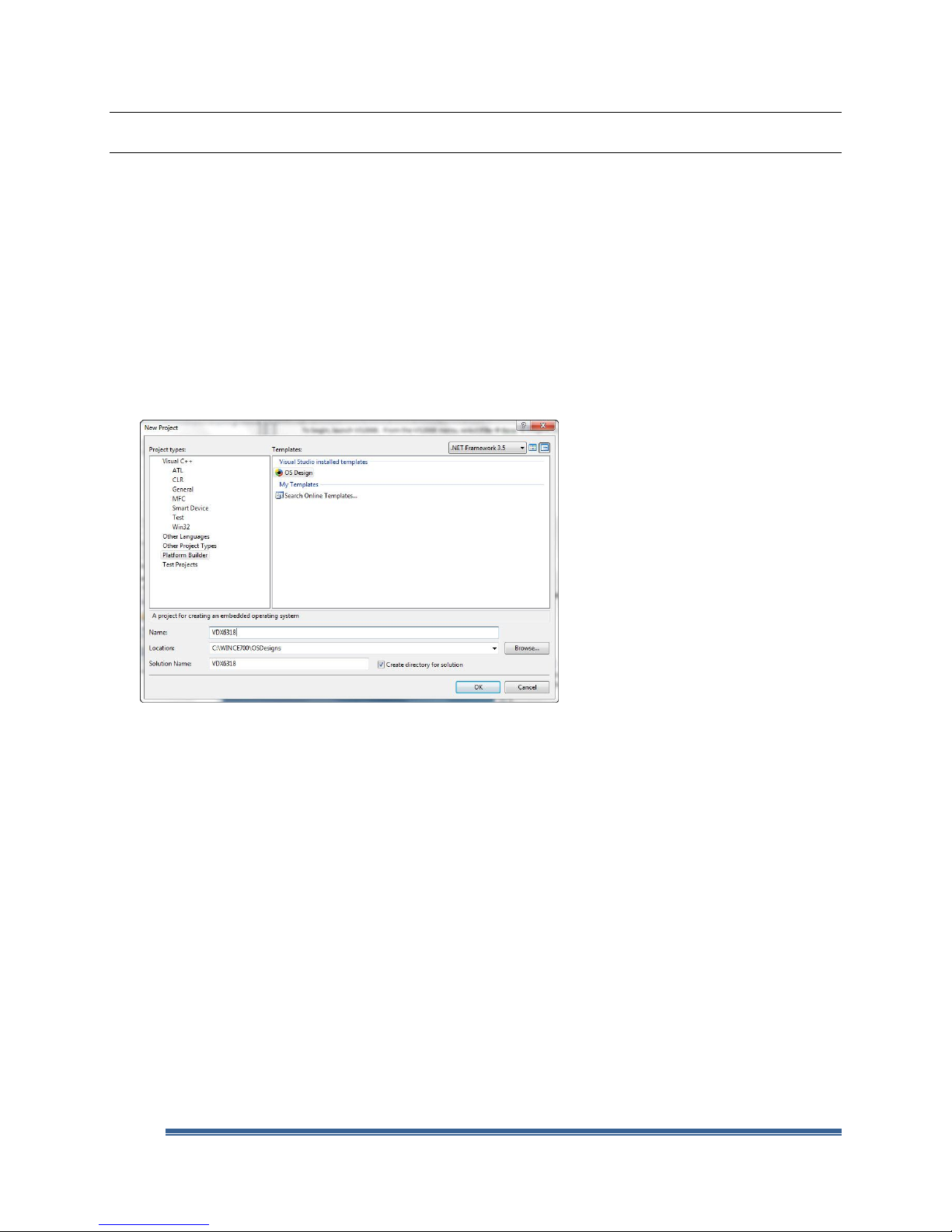
During the supported processor selection step, include support for the x86 Architecture, as shown in
Figure 6.
Fig. 6 - Supported processor architecture
Board-Support-Package Installation
VS2008 and Compact 7 must be installed prior to installing the Board-Support-Package (BSP). The
ICOP_VDX6318_70B BSP is provided on the jump start CD, in the \WinCE700 folder.
\WinCE700\ICOP_VDX6318_70B_BSP.msi
After installation, this BSP shows up on the Platform Builder 2008 component catalog as
“ICOP_VDX6318_70B : x86” under the \Third Party\BSP folder.
Windows Embedded Compact 7 Getting Started Rev 2.00 Page 17
Page 18

VDX-6318 Windows Embedded Compact 7 - Getting Started Guide
Note:
Files for the CoreCon component are installed to the development station as part of the Visual Studio
software installation.
For 32-bit Windows 7, XP and Vista development station, the CoreCon component files are installed to
the following directory:
\Program Files\Common Files\Microsoft Shared\CoreCon
For 64-bit Windows 7 development station, the CoreCon component files are installed to the following
directory:
\Program Files (x86)\Common Files\Microsoft Shared\CoreCon
SDK Installation
VS2008 and Compact 7 must be installed prior to installing the SDK. The Compact 7 SDK is needed
to support application development exercises in this guide, Vortex86DX_SDK_Compact7.msi, is
provided on the jump start CD, in the \WinCE700 folder.
\WinCE700\Vortex86DX_SDK_Compact7.msi
AutoLaunch Component Installation
The AutoLaunch catalog component for Compact 7 in self-installable file format,
AutoLaunch_v300_Compact7.msi, is provided with the jump start kit CD. To install, locate and
launch this component on the jump start CD, in the \WinCE700 directory.
\WinCE700\AutoLaunch_v300_Compact7.msi
After installation, this component shows up on the Compact 7 Platform Builder component catalog
as “AutoLaunch_v300_Compact7” under the “\Third Party\Embedded101” folder.
CoreCon Connectivity Component
In the previous version of the jump start kit, the CoreCon component was provided as a separate
component. For the exercise in this getting started guide, the CoreCon component is a subcomponent to the AutoLaunch component:
AutoLaunch_v300_Compact7/Autolaunch CoreCon
When the Autolaunch CoreCon sub-component is included in the OS design, it contains the
necessary command script and associated configuration parameters to include CoreCon files to the
final OS run-time image.
Windows Embedded Compact 7 Getting Started Rev 2.00 Page 18
Page 19
VDX-6318 Windows Embedded Compact 7 - Getting Started Guide
Part 4 – OS Design (Platform Builder Project)
In this section, with help from the OS Design wizard, you will work through the steps to create a new OS
design project.
Visual Studio 2008
The VS2008 IDE provides support to create different type of projects, such as Windows Application,
Console Application, Class Library, smart device application, Windows Services, Web Control, etc…
When starting a new project with VS2008, the VS2008 IDE provides different wizards and templates
to help create the initial workspace for the project. Platform Builder is one of the available project
types, to develop Compact 7 OS design project.
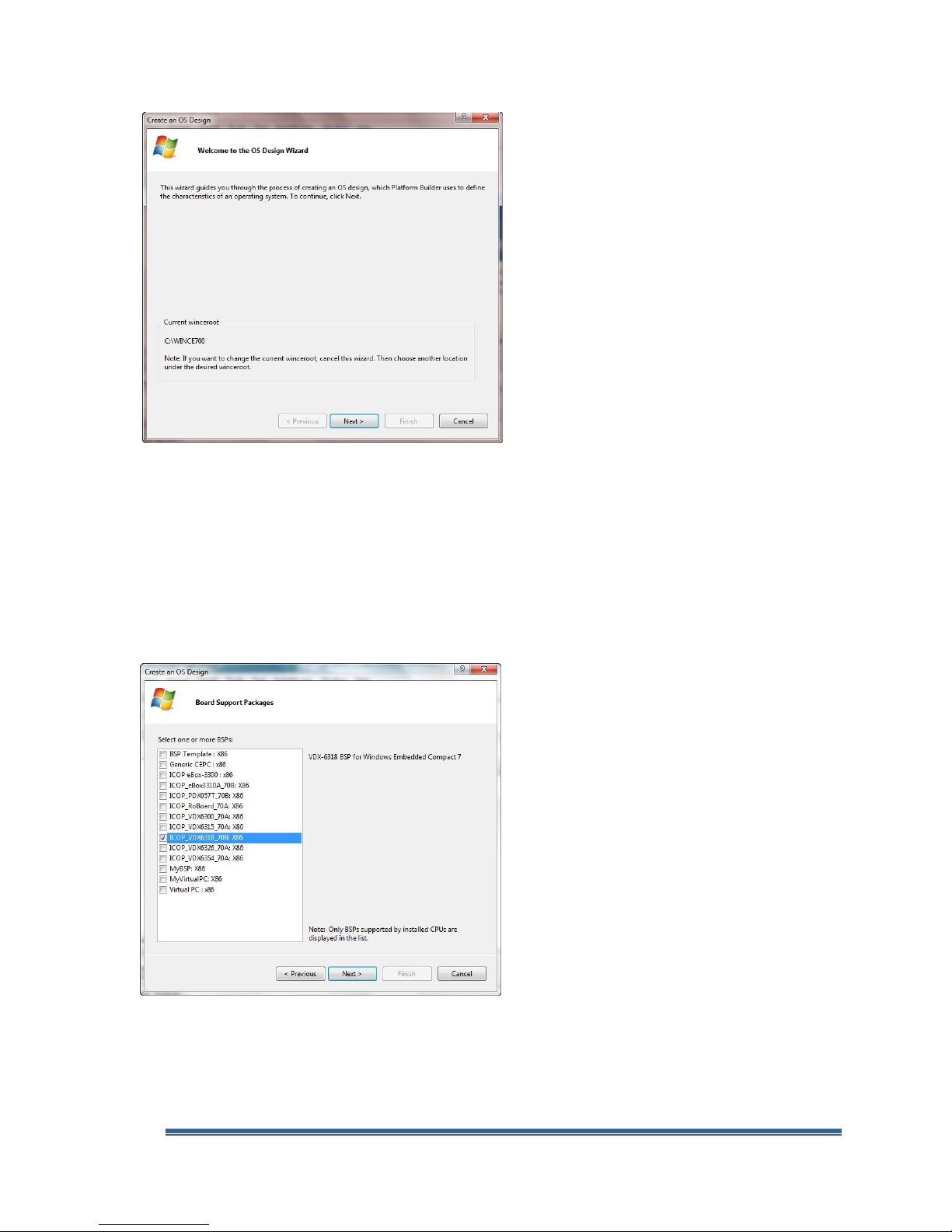
To begin, launch VS2008. From the VS2008 menu, select File → New → Project to bring up the new
project screen, as shown in Figure 7.
Fig. 7 - VS2008 New Project – Platform Builder 2008 (OS design)
From the New Project screen’s left pane, click to highlight the Platform Builder option.
From the right pane, click to highlight the OS Design option.
Enter VDX6318 as the name for the project.
Make sure the Create directory for solution check box is checked.
Click OK to continue.
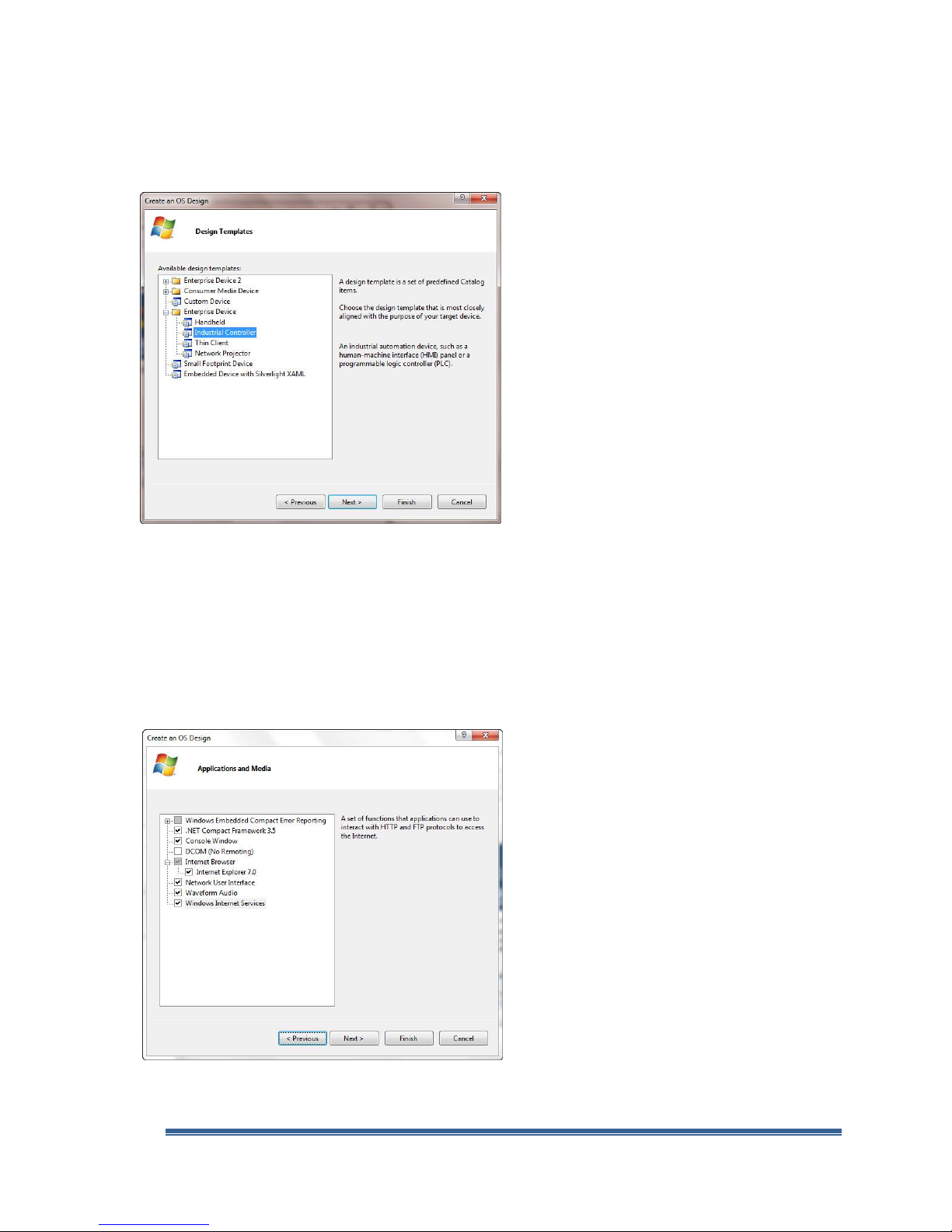
Windows Embedded Compact 7 OS Design Wizard
When a new Platform Builder OS design project is selected, the OS Design Wizard launches, as
shown in Figure 8, and guides you through the process to configure the initial OS design project
using templates available as part of the VS2008 IDE.
Windows Embedded Compact 7 Getting Started Rev 2.00 Page 19
Page 20
VDX-6318 Windows Embedded Compact 7 - Getting Started Guide
Fig. 8 - OS Design Wizard
Click Next to continue and bring up the Create an OS Design - Board Support Packages
selection screen.
OS Design Wizard – Board Support Package (BSP)
In the BSP selection step, the OS Design Wizard provides the options to select one or more BSP for
the new project from the list of available BSPs. All of the installed BSPs, including BSPs from
Microsoft and third party companies are listed on the Create an OS Design - Board Support
Packages screen, as shown in Figure 9.
Fig. 9 - OS design Wizard – Select BSP
From the Select one or more BSPs pane, select the ICOP_VDX6318_70B: x86 BSP.
Click Next to continue and bring up the Create an OS Design - Design Templates screen.
Windows Embedded Compact 7 Getting Started Rev 2.00 Page 20
Page 21
VDX-6318 Windows Embedded Compact 7 - Getting Started Guide
OS Design Wizard – Design Templates
In the design template selection step, the OS Design Wizard provides multiple design templates to
choose from, as shown in Figure 10.
Fig. 10 - OS design Wizard – Design Templates
Expand the Enterprise Device node and select the Industrial Controller template.
Click Next to continue and bring up the Create an OS Design - Application & Media screen.
OS Design Wizard – Applications & Media
In the applications & media selection step, the OS Design Wizard provides the options to select and
include the .NET Compact Framework, Internet Explorer, Network User Interface and other
components to the OS design, as shown in Figure 11.
Fig. 11 - OS Design Wizard – Applications & Media
Windows Embedded Compact 7 Getting Started Rev 2.00 Page 21
Page 22

VDX-6318 Windows Embedded Compact 7 - Getting Started Guide
In addition to the .NET Compact Framework 3.5 component, select and include the following
components to the OS design:
Console Window
Internet Explorer 7.0
Network User Interface
Waveform Audio
Windows Internet Services
Click Next to continue and bring up the Create an OS Design - Networking & Communication
screen.
OS Design Wizard – Networking & Communications
In the networking & communication selection step, the OS Design Wizard provides the options to
select communication, networking and security components, as shown in Figure 12.
Fig. 12 - OS Design Wizard – Networking & Communications
For the networking & communication selection step, keep the default selection.
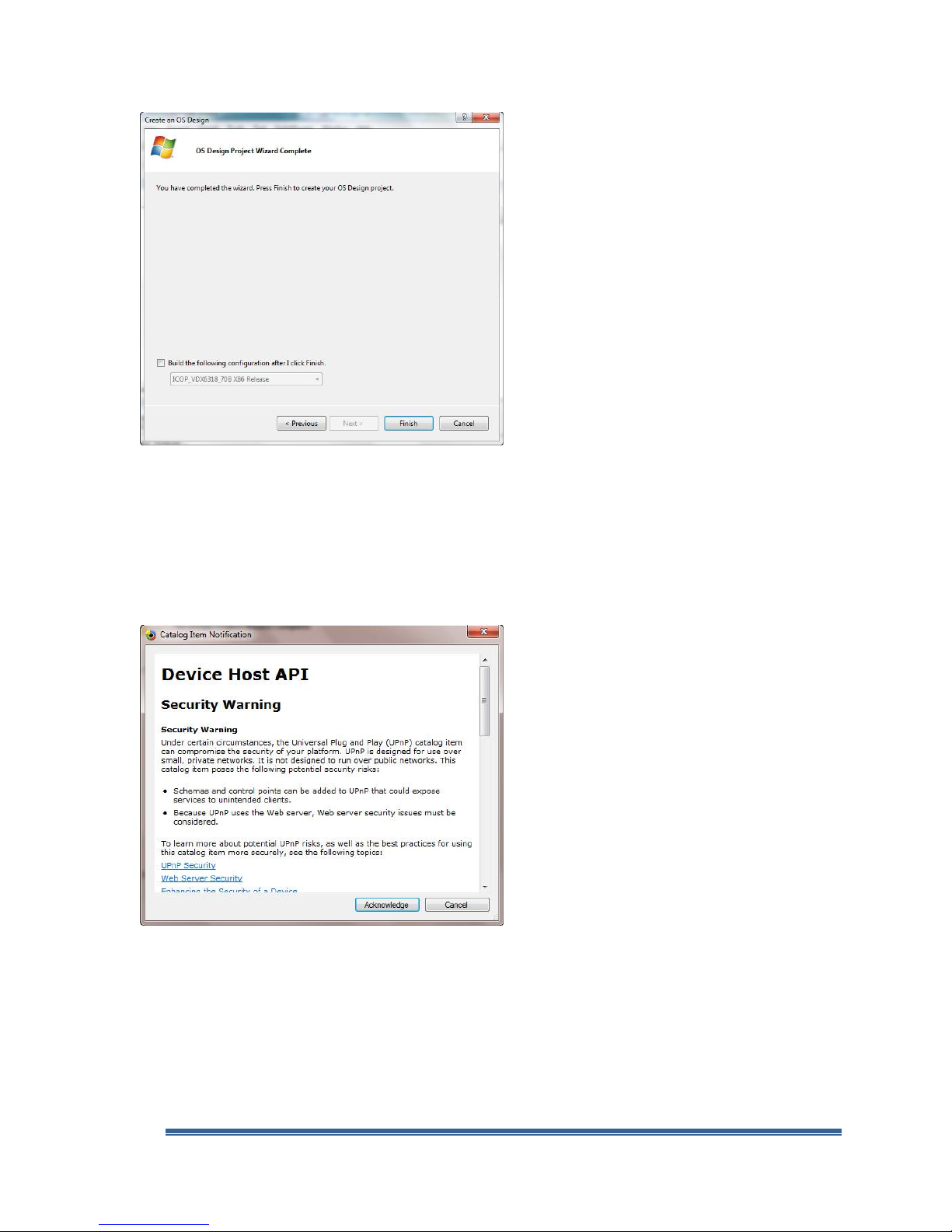
Click Next to continue and bring up the Create an OS Design - OS Design Project Wizard
Complete screen, as shown in Figure 13.
At this point, the OS Design Wizard included the necessary OS components needed to configure the
initial OS design project.
Windows Embedded Compact 7 Getting Started Rev 2.00 Page 22
Page 23
VDX-6318 Windows Embedded Compact 7 - Getting Started Guide
Fig. 13 - OS Design Wizard – Completed
Click Finish to complete the OS Design Wizard step.
Security Warning - Catalog Item Notification
At the completion of OS Design Wizard step, the Catalog Item Notification screen is raised, with
security warning, to warn one or more of the components included in the OS design may pose
security risk, as shown in Figure 14.
Fig. 14 - Catalog Item Notification – Security Warning
Click Acknowledge to acknowledge the warning and close the warning screen.
At the completion of the OS Design wizard step, the initial project workspace for the OS design is
created in the following directory:
C:\WINCE700\OSDesigns\VDX6318\
Windows Embedded Compact 7 Getting Started Rev 2.00 Page 23
Page 24
VDX-6318 Windows Embedded Compact 7 - Getting Started Guide
Part 5 – Configure and Customize Compact 7 OS Design
At this point, with help from the OS Design Wizard, the initial workspace for the OS design is created
using the Industrial Controller design template along with the ICOP_VDX6318_70B BSP and
components selected during the OS Design Wizard steps.
The following project folder and sub-folders are created for the OS design, under the main Compact 7
OS design project directory:
C:\WINCE700\OSDesigns\VDX6318\
This is the folder for the VDX6318 Solution. VS2008 supports different project types. A solution
provides a centralized work space to keep different project types supporting the same solution
in one location.
For example, the VDX6318 solution may include the “VDX6318 OS design”, “Visual Basic
managed code application”, “Visual C# managed code application” and “Visual C++ native code
application”.
C:\WINCE700\OSDesigns\VDX6318\VDX6318\
This is the folder for the VDX6318 OS design project.
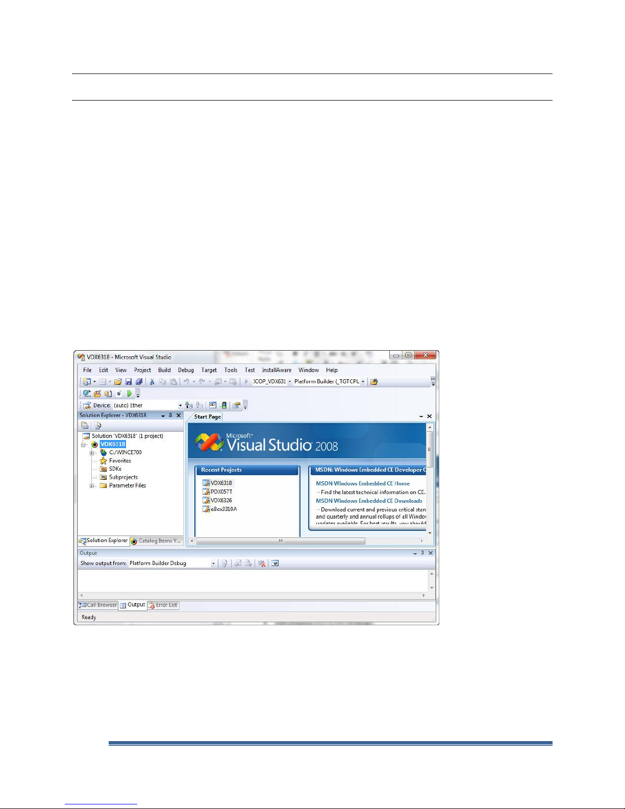
The VS2008 IDE should look similar to the screen as shown in Figure 15.
Fig. 15 - VS2008 IDE after OS Design Wizard
Customize the OS Design – Add Additional Components
The OS design can be further customized with the following:
Add component(s) to the OS design.
Remove component(s) from the OS design.
Windows Embedded Compact 7 Getting Started Rev 2.00 Page 24
Page 25
VDX-6318 Windows Embedded Compact 7 - Getting Started Guide
Add application and library as subproject to the OS design.
Modify system configuration and registry files to customize system behavior.
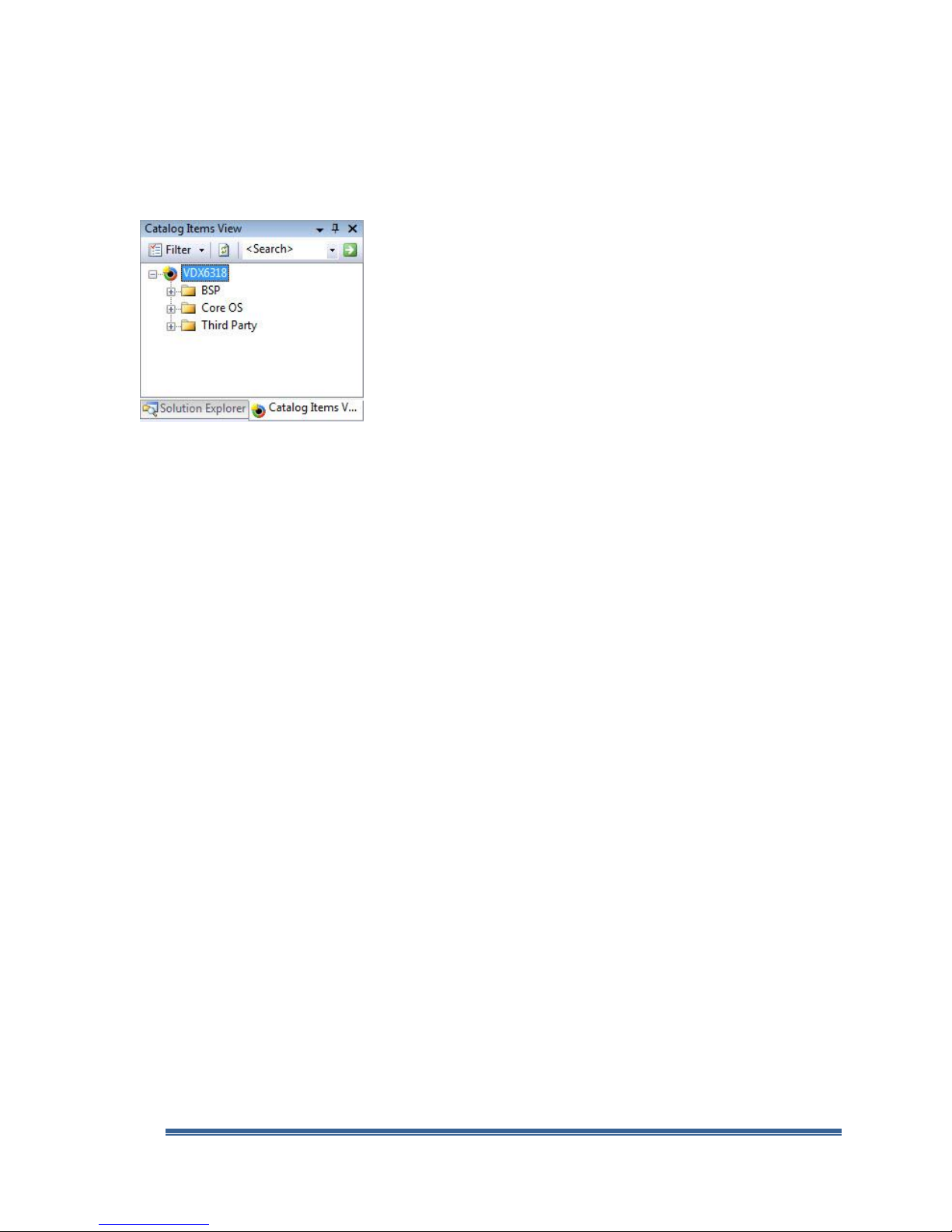
With the VDX6318 OS design project active, from the VS2008 menu, select View → Other Windows
→ Catalog Items View to bring up the Catalog Item View window, as shown in Figure 16.
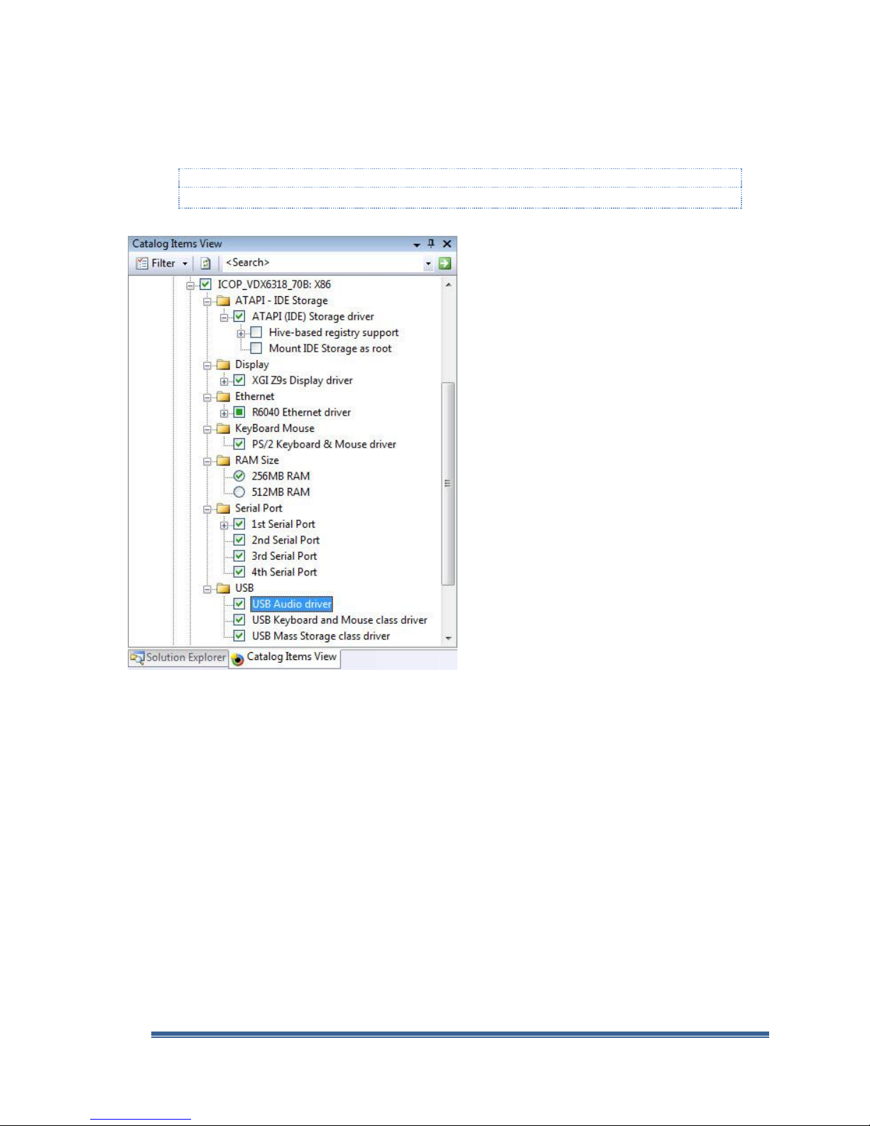
Fig. 16 - Catalog Items View (Component Catalog)
The Catalog Item View window on the VS2008 IDE contains all of the Compact 7 components,
including application, library, driver, utility and 3rd party components installed to the development
station which can be added to the OS design project.
From the Catalog Items View window, expand the component nodes and review the components
selected during OS Design Wizard steps:
o Component with a green check mark to the left indicates it was selected during the OS
Design Wizard steps, or manually added after the OS Design Wizard steps.
o Component with a solid green square to the left indicates the component is included to the
OS design as the result of being a dependency to another selected component.
o Component with a red cross to the left indicates the component is selected and is
dependent on one or more other components currently not included to the OS design.
(Component with a red cross to the left will not be included to the final image.)
Work through the following steps to customize the VDX6318 OS design project:
From the Catalog Items View window, expand the \Third Party\BSP node.
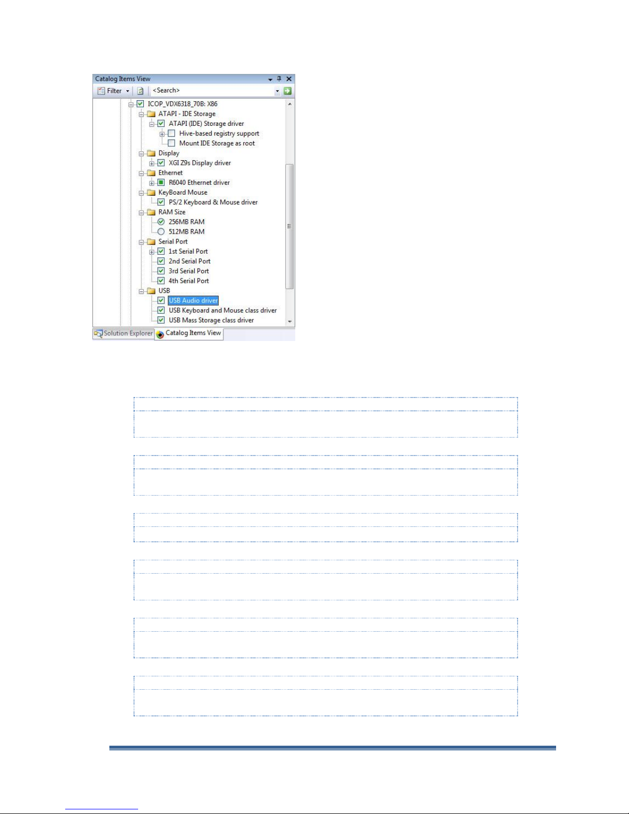
Expand all nodes under the ICOP_VDX6318_70B: X86 node, as shown in Figure 17.
Windows Embedded Compact 7 Getting Started Rev 2.00 Page 25
Page 26
VDX-6318 Windows Embedded Compact 7 - Getting Started Guide
Note:
The ATAPI (IDE) Storage component set the SYSGEN_ATAPI variable to include the ATAPI storage
driver, and the SYSGEN_FATFS variable to include FAT file system support.
Note:
The Hive-based registry component is needed to save registry settings to non volatile flash storage
between power reset.
Note:
Device driver to support the Z9s display controller.
Note:
The display setting is selected arbitrary for this HOL guide. You can select a different display
setting supported by the display monitor you are working with.
Note:
Device driver to support the R6040 Ethernet controller, built-in to the Vortex86DX System-OnChip.
Note:
This BSP component set the BSP_KEYBD_8042 environment variable to include the PS/2 Keyboard
and Mouse driver to the OS run-time image.
Fig. 17 - Catalog Items View (Component Catalog)
Check to ensure the following BSP components are selected and included to the OS design:
ATAPI (IDE) Storage driver
Hive-based registry support
Z9s XGI Display driver
VGA 1024x768x16 @ 60Hz
R6040 Ethernet driver
PS/2 Keyboard & Mouse driver
Windows Embedded Compact 7 Getting Started Rev 2.00 Page 26
Page 27

256MB RAM
Note:
The VDX-6318 SBC that comes with the jump start kit is built with 256MB. This component set the
IMGRAM256 environment variable and configure the OS run-time image to use the 256MB of
available system memory.
Improper system memory configuration can cause the Compact 7 OS run-time image not able to
complete the boot up process and reset the device.
Note:
This component set the BSP_SERIAL environment variable to include serial port driver to the OS
run-time to support COM1, the first serial port.
By default, the SBC’s first serial port is configured as follow:
- COM1: IRQ4, 3F8h
Note:
This component set the BSP_SERIAL2 environment variable to include serial port driver to the OS
run-time to support COM2, the second serial port.
By default, the SBC’s 2nd serial port is configured as follow:
- COM2: IRQ3, 2F8h
Note:
This component set the BSP_SERIAL3 environment variable to include serial port driver to the OS
run-time to support COM3, the third serial port.
By default, the SBC’s 3rd serial port is configured as follow:
- COM3: IRQ10, 3E8h
Note:
This component set the BSP_SERIAL4 environment variable to include serial port driver to the OS
run-time to support COM4, the fourth serial port.
By default, the SBC’s 4th serial port is configured as follow:
- COM4: IRQ11, 2E8h
Note:
This component set the BSP_VORTEX86DX_USB_AUDIO and SYSGEN_USB environment variables
to include the USB 2.0 driver and audio driver.
Note:
This component set the SYSGEN_USB_HID_CLIENTS environment variable to include the USB
Keyboard and Mouse HID class driver to the OS run-time image.
Note:
This component set the SYSGEN_USB_STORAGE environment variable to include the USB storage
class driver to the OS run-time image to support external USB storage.
st
1
2
Serial Port
nd
Serial Port
VDX-6318 Windows Embedded Compact 7 - Getting Started Guide
3rd Serial Port
4th Serial Port
USB Audio driver
USB Keyboard & Mouse (HID) class driver
USB Mass Storage class driver
Windows Embedded Compact 7 Getting Started Rev 2.00 Page 27
Page 28

VDX-6318 Windows Embedded Compact 7 - Getting Started Guide
Note:
This component provides application installation & removal support. It’s needed to support
VS2008 application debug and deployment.
Note:
.NET Compact Framework components are needed to support managed code application. During
the OS Design wizard steps, .NET Compact Framework 3.5 components are included to the OS
design project. Expand the \Core OS\Windows Embedded Compact\Applications and Services
Development node to validate these two .NET Compact Framework components are selected.
Note:
The FTP server provides a convenience mechanism to upload file(s) to the target device, and
download file(s) from the target device, using an FTP client.
In the later section, the following registry entries will be added to the project to enable the FTP
server and enable support for anonymous login to the FTP server:
[HKEY_LOCAL_MACHINE\COMM\FTPD]
"IsEnabled"=dword:1
"UseAuthentication"=dword:0
"UserList"="@*;"
"AllowAnonymous"=dword:1
"AllowAnonymousUpload"=dword:1
"AllowAnonymousVroots"=dword:1
"DefaultDir"="\\"
Note:
With the appropriate registry entries, the AutoLaunch utility can be configured to launch one or
more application automatically when the Compact 7 OS starts.
The following sample registry entries configure the AutoLaunch utility to launch App1.exe and
App2.exe with 5 and 10 seconds delay respectively.
[HKEY_LOCAL_MACHINE\Startup]
“Process2”= “App1.exe”
“Process2Delay”=dword:00001388 ; delay 5 seconds before launching App1.exe
“Process3”= “App2.exe –c”
“Process3Delay”=dword:00002710 ; delay 10 seconds before launching App2.exe
Expand the \Core OS\Windows Embedded Compact\Applications – End User node, locate and
include the following components to the OS design to support CAB file installation and application
deployment from the Visual Studio 2008 IDE:
CAB File Installer/Uninstaller
Expand the \Core OS\Windows Embedded Compact\Applications and Services Development node,
locate and include the following components to the OS design to support managed code application:
.NET Compact Framework 3.5
OS Dependencies for .NET Compact Framework 3.5
Expand the \Core OS\ Windows Embedded Compact\Communication Services and
Networking\Servers node, select and include the FTP server component to the OS design:
FTP Server
Expand the \Third Party\Embedded101 node, select and include the following AutoLaunch
components to the OS design, a utility to launch application during startup:
AutoLaunch_v300_Compact7
Windows Embedded Compact 7 Getting Started Rev 2.00 Page 28
Page 29
VDX-6318 Windows Embedded Compact 7 - Getting Started Guide
Note:
When this sub-component is added, it includes the command script to copy the necessary CoreCon
connectivity files to the OS design’s build release directory, and include the following registries to
launch CoreCon during startup:
[HKEY_LOCAL_MACHINE\Startup]
“Process0”=”ConmanClient2.exe”
“Process0Delay”=dword:00001388
[HKEY_LOCAL_MACHINE\System]
“CoreConOverrideSecurity”=dword:1
Note:
When this sub-component is added to the OS design, it sets the SYSGEN_CERDISP variable to
include the Remote Display application to the OS design and include the following registry entries
to launch the Remote Display application during startup:
[HKEY_LOCAL_MACHINE\Startup]
“Process1”=”cerdisp -c”
“Process1Delay”=dword:00002710
AutoLaunch_v300_Compact 7\Autolaunch CoreCon
AutoLaunch_v300_Compact 7\Autolaunch Remote Display application
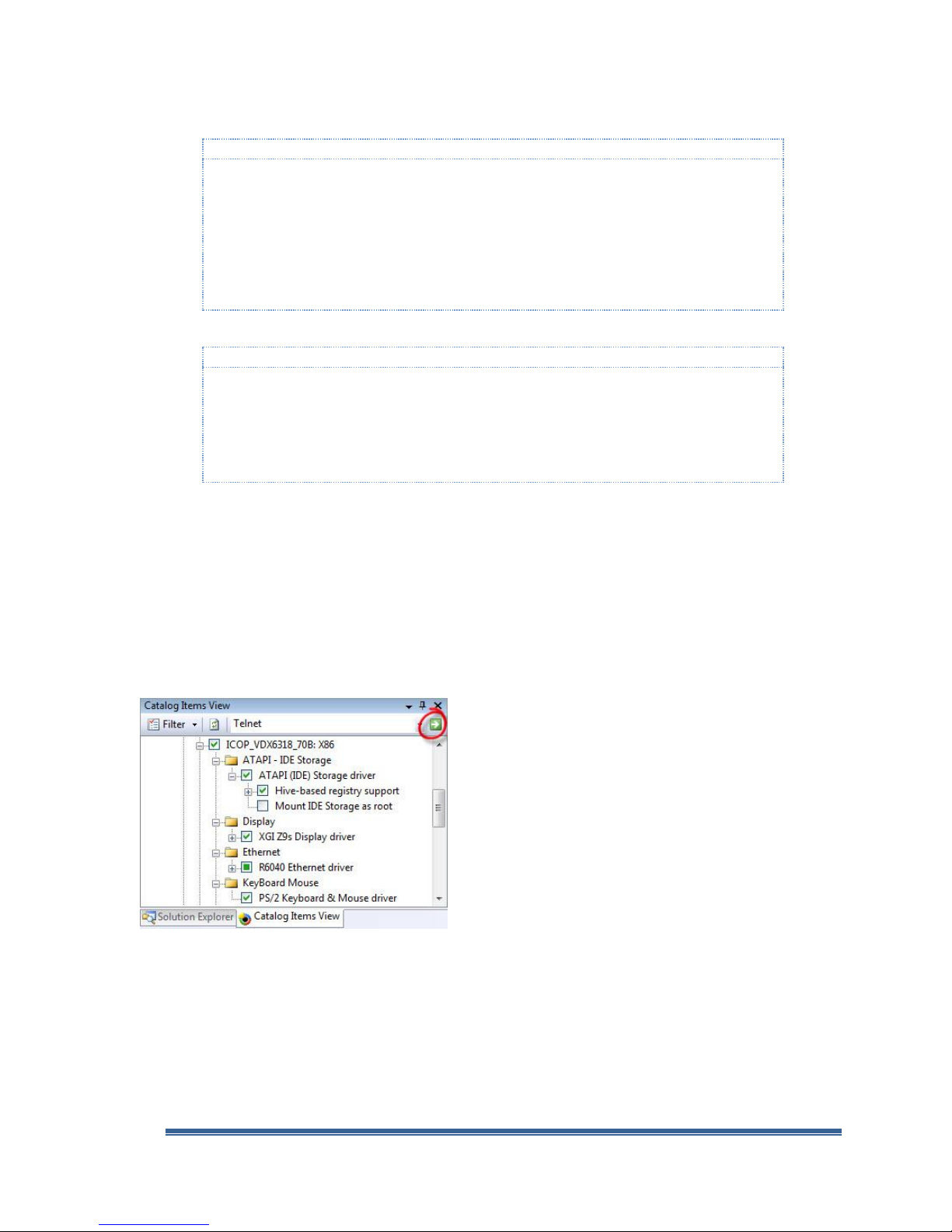
Customize the OS Design – Locate Component by Search
The VS2008 IDE provides the search function to locate Compact 7 component from the catalog by
searching the catalog using key-word or partial key-word associated with the component. In this
section, you will use the search function to locate a component from the catalog and add the
component to the OS design.
From the Catalog Item View tab, enter Telnet in the search text box on the top right, and click the
green arrow to the right of the search text box to locate the Telnet Server component, as shown in
Figure 18.
Fig. 18 - Locate component using the search feature
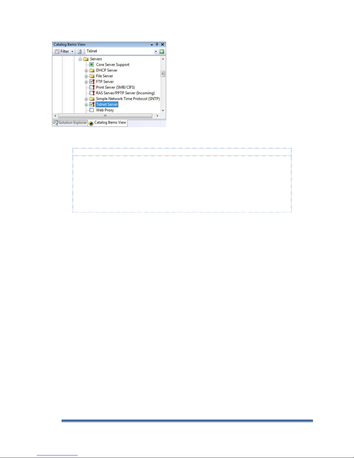
The search engine locates and highlights the Telnet Server component, as shown in Figure 19.
Windows Embedded Compact 7 Getting Started Rev 2.00 Page 29
Page 30
VDX-6318 Windows Embedded Compact 7 - Getting Started Guide
Note:
The Telnet Server component provides a convenience mechanism to access and the compact 7
device remotely. When this component is added to the OS design, it does not include the necessary
registry entries to launch the Telnet server.
In the later section, the following registry entries will be added to the project to enable the Telnet
server and enable support for anonymous login:
[HKEY_LOCAL_MACHINE\COMM\TELNETD]
"IsEnabled"=dword:1
"UseAuthentication"=dword:0
Fig. 19 - Locate component using the search feature
Select and include the Tenet Server component in the OS design.
Customize the OS Design – Configuration Manager
Using the configuration manager, the OS design can be configured to generate an OS run-time
image in checked, debug or release mode. An OS image built in release mode is optimized for
distribution, does not contain ASSERT and not able to output DEBUGMSG. An image built in debug
mode is not optimized and include additional resource to support debugging. However, a debug
mode image, without optimization, can be difficult to debug certain type of timing and performance
related problems. An image built in Checked mode (Checked mode is new to Compact 7), a hybrid
between the debug and release modes, is built with compiler optimization, contains ASSERT,
DEBUGMSG and RETAILMSG to provide the necessary resources needed for debugging.
A debug mode image will provide more detailed debug messages when the OS image loads and
executes applications and modules. The size of an OS image built in debug mode is generally about
50% larger than an OS image built in release mode, from the same OS design project. An OS image
built in release mode, with KITL enabled, provides sufficient debug information to support most of
the general application development environment. For the exercise in this guide, you will configure
the OS design to generate an OS run-time image in release mode.
From the VS2008 menu, select Build → Configuration Manager to bring up the
Configuration Manager screen, as shown in Figure 20.
Windows Embedded Compact 7 Getting Started Rev 2.00 Page 30
Page 31

VDX-6318 Windows Embedded Compact 7 - Getting Started Guide
Note:
When deploying a Compact 7 OS run-time image with KITL enabled to the target device’s local flash
storage, the system will search for an unavailable KITL connection during start up and will not be
able to complete the boot process.
Fig. 20 - Configuration Manager
From the Active solution configuration selection options, select ICOP_VDX6318_70B x86
Release and click Close to configure the OS design to generate a release mode image.
By default, the VDX6318 OS design is configured to generate run-time image in release mode. The
exercise in this section demonstrates the available options to configure the OS design to generate
run-time image in checked, debug and release modes.
Customize the OS Design – Build Options
The OS design can be further customized by editing the project’s build options.
From the VS2008 menu, select Project → VDX6318 Properties to bring up the VDX6318 Property
Pages screen, as shown in Figure 21.
Fig. 21 - OS design Property – Build Options
From the left pane, expand the Configuration Properties node and select Build Options.
From the right pane, change the following build options:
Set Enable KITL build option to No
Windows Embedded Compact 7 Getting Started Rev 2.00 Page 31
Page 32

VDX-6318 Windows Embedded Compact 7 - Getting Started Guide
Click Apply and OK to close the VDX6318 Property Pages screen.
Customize the OS Design – The Registry
The registry plays a key role in controlling how the Compact 7 OS run-time behave, loads driver,
application and more. Improper registry entries can cause series problem and can cause the system
failing to complete the boot process.
In the earlier steps, the FTP server and Telnet server components were included to the OS design. In
order for these components to function as intended, appropriate registry entries need to be added
to the OS design project.
Registry Entries for FTP Server Component
By default, the FTP server is not configured to launch during startup. For the exercise in this
guide, the following registry entries need to be added to the OS design and configure the FTP
server to launch during startup, with user authentication disabled and allow anonymous login:
[HKEY_LOCAL_MACHINE\COMM\FTPD]
"IsEnabled"=dword:1
"UseAuthentication"=dword:0
"UserList"="@*;"
"AllowAnonymous"=dword:1
"AllowAnonymousUpload"=dword:1
"AllowAnonymousVroots"=dword:1
"DefaultDir"="\\"
Registry Entries for the Telnet Server Component
By default, the Telnet server is not configured to launch during startup. For the exercise in this
guide, the following registry entries are added to configure the Telnet server to launch during
startup and allow anonymous login:
[HKEY_LOCAL_MACHINE\COMM\TELNETD]
"IsEnabled"=dword:1
"UseAuthentication"=dword:0
Registry Entries for the AutoLaunch Component
When the AutoLaunch component is added to the OS design, the following registry entries are
added to the project as part of the AutoLaunch component, to launch the AutoLaunch.exe
executable during startup:
[HKEY_LOCAL_MACHINE\Init]
"Launch99"="AutoLaunch.exe"
"Depend99"=hex:0a,00,14,00
When the AutoLaunch utility launches, it searches the following registry key and launch
application with proper entries under this key:
[HKEY_LOCAL_MACHINE\Startup]
As part of the AutoLaunch_v300_Compact7 release, two sub-components are included which
you can select and include CoreCon connectivity and Remote Display application components to
the OS design. “Process0” and “Process1” under the HKLM\Startup key are used by these two
components.
To configure the AutoLaunch utility to launch other application component, start with
“Process2” as follow:
Windows Embedded Compact 7 Getting Started Rev 2.00 Page 32
Page 33

VDX-6318 Windows Embedded Compact 7 - Getting Started Guide
Note:
The process delay entries above are randomly selected. You can configure the delay based on your
need.
3A98 in HEX equal to 15000 in decimal, which represent 15000 ms or 15 seconds
You can configure the delay to control startup sequence between multiple applications.
[HKEY_LOCAL_MACHINE\Startup]
"Process2"="App_01.exe"
"Process2Delay"=dword:3A98
"Process3"="App_02.exe"
"Process3Delay"=dword:4E20
Adding Registry Entries to OS Design
Work through the following steps to add the necessary registry entries for the FTP Server and
Telnet Server to the OS design:
From the VS2008 menu, select View →Solution Explorer to bring up the Solution
Explorer window.
From the Solution Explorer window, expand the \Parameter Files node, and double
click on OSDesign.reg to open this file in the code editor window.
On the code editor window’s lower left, click on Source to view the OSDesign.reg
registry file in source code format.
Scroll to the end of the file and add the following entries to OSDesign.reg:
; Registry entries for the FTP server component
[HKEY_LOCAL_MACHINE\COMM\FTPD]
"IsEnabled"=dword:1
"UseAuthentication"=dword:0
"UserList"="@*;"
"AllowAnonymous"=dword:1
"AllowAnonymousUpload"=dword:1
"AllowAnonymousVroots"=dword:1
"DefaultDir"="\\"
; Registry entries for the Telnet server component
[HKEY_LOCAL_MACHINE\COMM\TELNETD]
"IsEnabled"=dword:1
"UseAuthentication"=dword:0
Static IP Address
By default, the OS design generates a Compact 7 OS run-time image with DHCP enable to request IP
address dynamically. During the development process, it may be convenient to configure a Compact
7 OS run-time image preconfigured with static IP address, and provide a known IP to work with.
The OS design can be configured to generate an OS run-time image with preconfigured static IP
address by adding the following registry entries to OSDesign.reg:
[HKEY_LOCAL_MACHINE\Comm\PCI\R60401\Parms\TcpIp]
"EnableDHCP"=dword:0
"DefaultGateway"=multi_sz:"192.168.2.1"
"UseZeroBroadcast"=dword:0
"IpAddress"=multi_sz:"192.168.2.232"
"Subnetmask"=multi_sz:"255.255.255.0"
Windows Embedded Compact 7 Getting Started Rev 2.00 Page 33
Page 34

VDX-6318 Windows Embedded Compact 7 - Getting Started Guide
Note:
When the KITL build option is enabled, the Compact 7 OS run-time image is generated with the
VMINI driver to support debugging, which is different from the driver for the R6040 Ethernet
controller.
The registry entries under the HKEY_LOCAL_MACHINE\Comm\VMINI1\Parms\TcpIp key are needed
to support the KITL connectivity.
Static IP is not required for the exercises in this guide.
SBC Peripherals
Compact 7 Drivers & Support Components
Z9s display
Display driver (Driver included with BSP)
USB Audio
Audio driver (Driver included with BSP)
R6040 Ethernet Driver
Ethernet driver (Driver included with BSP)
Serial Ports
Com16550 (Driver available from Platform Builder’s component
catalog)
USB Ports (USB 2.0
Host)
USB host drivers (Driver available from Platform Builder’s component
catalog)
IDE
ATAPI (Driver available from Platform Builder’s component catalog)
[HKEY_LOCAL_MACHINE\Comm\VMINI1\Parms\TcpIp]
"EnableDHCP"=dword:0
"IpAddress"=multi_sz:"192.168.2.233"
"Subnetmask"=multi_sz:"255.255.255.0"
Other Compact 7 Components
In addition to the components selected during the OS design Wizard step and the components
automatically included in the OS design by the template, additional components from the catalog
can be added to the OS design to provide additional function and features.
For example, the File Server component can be added to provide files and folders sharing over a
network connection. The FTP Server component can be added to provide remote file upload and
download services. The RAS Server/PPTP Server (Incoming) component can be added to provide
inbound dialup network connection via the serial port.
The following table lists the SBC’s I/O peripherals and their associated Compact 7 device drivers and
support components:
The SBC used to develop the exercise for this guide is configured to boot from an IDE bootable flash
storage. The flash storage is attached to the SBC’s IDE interface. The IDE flash storage behaves just
like a typical IDE hard disk and requires the ATAPI driver and FAT file system components to
function.
To learn more about each of the Compact 7 components on the catalog, refer to the Compact 7 help
document from the development station, or from the following MSDN URL:
Windows Embedded Compact Documentation
http://msdn.microsoft.com/en-us/library/ee504813.aspx
Windows Embedded Compact 7 Getting Started Rev 2.00 Page 34
Page 35

VDX-6318 Windows Embedded Compact 7 - Getting Started Guide
Part 6 – Build and Generate Compact 7 OS Run-time
Image
In the previous sections, you created an OS design project, configured and customized the OS design. In
this section, you will work through the steps to build and generate a custom Compact 7 OS run-time
image from the OS design.
The Build Process – Starting
From the VS2008 menu, with the VDX6318 OS design project active, select Build → Advanced Build
Commands → Sysgen (blddemo -q) to build and generate an OS run-time image from the OS design.
Fig. 22 - VS2008 IDE showing the OS design being built.
Depending on the development station’s processor speed and available system resources, the build
process may take anywhere from 10 to well over 30 minutes.
During the build process, the output tab on the VS2008 IDE displays compilation activities, as shown
in Figure 22.
The Build Process – Completed
When the build process is completed, the VS2008 IDE should look similar to the screen, as shown in
Figure 23.
Windows Embedded Compact 7 Getting Started Rev 2.00 Page 35
Page 36

VDX-6318 Windows Embedded Compact 7 - Getting Started Guide
Note:
When the build process ended with 1 or more error, the build process failed and will not generate a
Compact 7 OS run-time image file. When the build process ended with warnings and without any
error, the build process is completed with a Compact 7 OS run-time image file generated.
The number of warning may vary depending on the selected components and installed QFE. When
working with a known good BSP, the warnings are generally non critical and do not impact system
function. However, as part of good engineering practice, it’s good to go through the warning
messages to identify potential problem.
Fig. 23 - VS2008 IDE – Build completed
The Output tab on the VS2008 IDE shows the result of the build process, with “0” failed task.
With a successful build, a Compact 7 OS run-time image file, NK.BIN, is generated in the following
build release directories:
For OS design configured to generate an image in checked mode:
\WINCE700\OSDesigns\VDX6318\VDX6318\RelDir\ICOP_VDX6318_70B_x86_Checked
For OS design configured to generate an image in debug mode:
\WINCE700\OSDesigns\VDX6318\VDX6318\RelDir\ICOP_VDX6318_70B_x86_Debug
For OS design configured to generate an image in release mode:
\WINCE700\OSDesigns\VDX6318\VDX6318\RelDir\ICOP_VDX6318_70B_x86_Release
Searching the above directories, with a successful build, there should be a NK.BIN file, which is the
Compact 7 OS run-time image file. After the build process is completed, Platform Builder generates
the following log files for the last build process:
C:\WINCE700\Build.log (This file list all of the build steps in detail.)
C:\WINCE700\Build.wrn (This file list all of the warnings during the build process.)
C:\WINCE700\Build.err (This file list all the errors during the build process. This file is not
present for a successful build.)
Windows Embedded Compact 7 Getting Started Rev 2.00 Page 36
Page 37

VDX-6318 Windows Embedded Compact 7 - Getting Started Guide
Note:
Refer to appendix A and B for more information about connectivity for downloading OS run-time image
from the development station to target device.
Part 7 – Download Compact 7 OS Run-time to Target
Device
To download the run-time image to the target device, you need to establish connectivity between the
VS2008 development station and target device.
In this section, you will work through the steps to establish connectivity and download the Compact 7
OS run-time image created in the earlier steps to the target device.
A target device built with different type of processor and I/O peripherals may require different transport
mechanism to establish the connectivity. The SBC is built with an x86 processor (Vortex86DX) and will
use the integrated Ethernet to establish connectivity to the VS2008 development station.
To work through the exercises in this guide, both the development station and target device must be
connected to the same LAN, using one of the following connectivity options:
1. Both the development station and target device are connected to the same LAN with DHCP
service to provide IP addresses dynamically.
2. Both the development station and target device are connected to the same LAN without DHCP
service and need to configure static IP addresses.
3. The target device is connected to the development station directly using a cross-over Ethernet
cable and need to configure static IP addresses.
The exercises in this guide are created with both the development station and target device connected
to the same LAN with DHCP service to provide IP addresses dynamically.
Target Device Preparation
The target device needs to be configured with an appropriate bootloader to establish connectivity
and download Compact 7 OS run-time image from the development station.
The target device provided as part of the jump start kit is shipped with an IDE flash configured with
BIOSLoader to launch the following preconfigured software:
NK.BIN
This is a Compact 7 OS run-time image generated from the VDX6318 OS design exercise in this guide,
with Hive-based registry enabled and AutoLaunch component configured to launch the included
CoreCon connectivity component to support application development using VS2008.
NK2.BIN
This is a Compact 7 OS run-time image generate from the same VDX6318 OS design with Hive-based
registry disabled and without the AutoLaunch and CoreCon components.
EBOOT.BIN
This is the Ethernet bootloader for the target device, needed to establish connectivity with the
development station to download OS run-time image. The EBOOT.BIN Ethernet bootloader needs to
be launched by another bootloader, such as Loadcepc or BIOSLoader.
After power up, the target device display the Compact 7 splash screen for about 10 seconds before
launching the default OS run-time image, NK.BIN.
Windows Embedded Compact 7 Getting Started Rev 2.00 Page 37
Page 38

VDX-6318 Windows Embedded Compact 7 - Getting Started Guide
Note:
The exercise in this section is applicable to development environment using dynamic IP addresses
with DHCP, and development environment using static IP addresses.
While the splash screen is showing, you can press “1” or “2” before the 10 seconds delay timed-out
to perform the following:
Press “1” to launch EBOOT.BIN to establish connectivity to the Platform Builder
development station and download OS run-time image from an active OS design.
Press “2” to launch the alternative OS run-time image, NK2.BIN.
Create Connectivity Profile for a Target Device
To establish connectivity and download Compact 7 OS run-time image from the development
station to the target device, you need to configure a target device connectivity profile and associate
the profile to the target device in use.
In this section you will work through the steps to create a target device connectivity profile and
associate this profile with the SBC, as the target device for the exercise in this guide.
Continue from the previous exercise, with the VDX6318 OS design project active, from the VS2008
menu, select Target → Connectivity Options to bring up the Target Device Connectivity Options
screen, as shown in Figure 24.
Fig. 24 - Target Device Connectivity Options
Work through the following steps to create a connectivity profile for the target device:
From the Target Device Connectivity Options screen, click Add Device to bring up the
screen to add a new target device profile as shown in Figure 25.
Windows Embedded Compact 7 Getting Started Rev 2.00 Page 38
Page 39

VDX-6318 Windows Embedded Compact 7 - Getting Started Guide
Fig. 25 - Target Device Connectivity Options – Add new device
Enter MyTargetDevice as the new target device name
Click Add to continue
The Target Device Connectivity Options screen displays the new device profile, MyTargetDevice, as
shown in Figure 26.
Fig. 26 - Target Device Connectivity Options – MyTargetDevice created
Select Ethernet for the Download option.
Select Ethernet for the Transport option.
Select KdStub for the Debugger option.
Click Apply to continue and save the settings.
Associate VDX-6318 to MyTargetDevice Connectivity Profile
In this section, you will work through the steps to associate the VDX-6318 SBC to the
MyTargetDevice connectivity profile, created in the previous section.
Windows Embedded Compact 7 Getting Started Rev 2.00 Page 39
Page 40

VDX-6318 Windows Embedded Compact 7 - Getting Started Guide
From the Target Device Connectivity Options screen (continuing from previous section), clicks on
the top most Settings button, to bring up the Ethernet Download Settings screen, as shown in
Figure 27.
Fig. 27 - Ethernet Download Settings
The Ethernet Download Settings screen is waiting for BOOTME messages from the target device's
Ethernet bootloader (EBOOT.BIN).
Work through the following steps to associate the SBC to this device profile:
Apply power to the target device.
AS the target device power up and display the Windows Embedded Compact 7 splash
screen, press “1” to launch the Ethernet bootloader, EBOOT.BIN.
As the EBOOT.BIN Ethernet bootloader is launched, it broadcasts a series of BOOTME
messages to the attached LAN via UDP.
As the Ethernet Download Settings screen detected the BOOTME messages from the target
device, it displays the device ID from the target device, as shown in Figure 28.
Windows Embedded Compact 7 Getting Started Rev 2.00 Page 40
Page 41

VDX-6318 Windows Embedded Compact 7 - Getting Started Guide
Note:
In the environment where there are multiple target devices connected to the same network
segment booting up and send bootme requests at about the same time, multiple device IDs will be
listed in the Active Devices windows. To identify the target device you are working with, make sure
it’s the only target device booting and sending the bootme request.
Fig. 28 - Ethernet Download Settings
Click and highlight the device ID listed in the Active target devices windows to associate the
device ID to the profile.
Click Apply to continue.
After the device ID is detected and accepted in the Active target devices step, the same device ID is
now shown on the Target Device Connectivity Options screen, as shown in Figure 29.
Fig. 29 - Ethernet Download Settings
Click Apply and Close to save the settings and close the Target Device Connectivity Options
screen.
Windows Embedded Compact 7 Getting Started Rev 2.00 Page 41
Page 42

VDX-6318 Windows Embedded Compact 7 - Getting Started Guide
Note:
Once launched, the Ethernet bootloader, EBOOT.BIN, will continue to broadcast BOOTME messages
to the development station and timed out after about 3 minutes. If you failed to initiate the OS runtime image before the timed out period, you need to re-initiate the download process again.
Download Compact 7 OS Run-time Image to VDX-6318
With the MyTargetDevice connectivity profile created and the SBC target device associated with this
profile, you are ready to download the Compact 7 OS run-time image from the Development station
to the target device.
Work through the following steps to download the OS run-time image to the target device:
From the VS2008 IDE, select and use MyTargetDevice device profile as shown in Figure 30.
Fig. 30 - select MyTargetDevice from VS2008 IDE
From the VS2008 menu, select Target → Attach Device to initiate the download process and
bring up the Device Status screen, as shown in Figure 31.
Fig. 31 - Waiting for bootme request from target device
Power on (or reset power) the target device.
As the Compact 7 splash screen is showing, press “1” to launch the Ethernet bootloader,
EBOOT.BIN, before the 10 seconds delay is timed out.
As the EBOOT.BIN launches, it sends a series of BOOTME messages to the development
station to trigger the OS run-time image download process.
As the image download takes place, the Device Status screen displays download activities,
as shown in Figure 32.
Windows Embedded Compact 7 Getting Started Rev 2.00 Page 42
Page 43

VDX-6318 Windows Embedded Compact 7 - Getting Started Guide
Fig. 32 - Downloading OS run-time image to the target device
After the image download process is completed, the Compact 7 OS run-time image downloaded to
the target device will launch. Be patient… It takes a few moments for the image to boot up.
When the Windows Embedded Compact 7 screen is displayed on the target device, it’s an indication
the boot process is completed, as shown in Figure 33.
Fig. 33 - Windows Embedded Compact 7 desktop from the target device
Deploy Compact 7 OS Run-time Image to Target Device
In the previous step, when the Compact 7 OS image is downloaded and launched on the target
device, the image is placed directly to the device’s memory (RAM) and is not saved to the device’s
local storage. After going through power reset, the downloaded image will be lost. To deploy a
Compact 7 OS run-time image to the target device’s local storage, the OS run-time image file,
NK.BIN, needs to be copied to the local storage and configured with an appropriate bootloader.
The NK.BIN OS run-time image file, in release mode, is generated in the following directory:
C:\WINCE700\OSDesigns\VDX6318\VDX6318\RelDir\ICOP_VDX6318_70B_x86_Release
Windows Embedded Compact 7 Getting Started Rev 2.00 Page 43
Page 44

VDX-6318 Windows Embedded Compact 7 - Getting Started Guide
Note:
Release mode image built with KITL enabled and debug image is not intended for deployment to the
target device’s local storage.
When deploying a release mode OS run-time image, generated with KITL enabled, to the target
device’s local storage, the image attempt to establish connectivity to an unavailable KITL connection
and will not be able to complete the boot process.
There are multiple methods to deploy the NK.bin OS run-time image file to the target device’s local
storage.
To deploy a Compact 7 OS run-time image to the target device’s local storage, the OS design must
be configured with the following:
Generate OS run-time image in release mode
Disable the KITL build option and other build option configured to support debugging
Refer to appendix H for more information about deploying a Compact 7 OS run-time image to the
target device’s local storage using DiskPrep, a Windows Embedded Compact power toy.
The DiskPrep power toy is available for download from the following URL:
http://code.msdn.microsoft.com/DiskPrep
Windows Embedded Compact 7 Getting Started Rev 2.00 Page 44
Page 45

VDX-6318 Windows Embedded Compact 7 - Getting Started Guide
Part 8 – Software Development Kit (SDK)
In this section, you will work through the steps to create and configure an SDK from the OS design
project. An SDK is needed to support Compact 7 application development for the target device.
Create and Configure Compact 7 SDK
With the VDX6318 OS design project active, from the VS2008 menu, select Project → Add New SDK
to bring up the SDK Property Pages screen, as shown in Figure 34.
Fig. 34 - New SDK Property Page
Enter Vortex86DX_SDK_Compact7 as SDK name
Enter Windows Embedded Compact 7 SDK for Vortex86DX Hardware as product name
Fill in the company name and company website information.
From the left pane, click on the Install node and enter Vortex86DX_SDK_Compact7.msi as
the file name on the right, as shown in Figure 35.
Fig. 35 - SDK Property Page
Windows Embedded Compact 7 Getting Started Rev 2.00 Page 45
Page 46

VDX-6318 Windows Embedded Compact 7 - Getting Started Guide
On the left pane, click on the Development Languages node to bring up the development
languages configuration, and enable support for both the Native and Managed
development, as shown in Figure 36.
Fig. 36 - SDK Property Page
Click Apply follow by OK to complete configuring the new SDK.
To make changes to the SDK before compiling, from the VS2008 IDE’s Solution Explorer tab, expand
the \SDKs folder, right click on Vortex86DX_SDK_Compact7 and select Properties to bring up the
SDK Properties Pages, as shown in Figure 37.
Fig. 37 - VS2008 IDE – Edit SDK
Windows Embedded Compact 7 Getting Started Rev 2.00 Page 46
Page 47

VDX-6318 Windows Embedded Compact 7 - Getting Started Guide
Note:
The OS design project must be built prior to launching the SDK build step. The SDK build process
requires library files generated during the OS design build process.
Build and Generate Compact 7 SDK
With the Vortex86DX_SDK_Compact7 SDK created, you can build and generate the SDK.
From VS2008 menu, select Build → Build All SDKs to build and generate the installation package for
the SDK. After the build process is completed, the Vortex86DX_SDK_Compact7.msi installation
package is generated in the following folder:
\WINCE700\OSDesigns\VDX6318\VDX6318\SDKs\SDK1\MSI
After the Vortex86DX_SDK_Compact7.msi installation package is generated, install this SDK to the
development station to support Compact 7 application development for the target device.
Windows Embedded Compact 7 Getting Started Rev 2.00 Page 47
Page 48

VDX-6318 Windows Embedded Compact 7 - Getting Started Guide
Note:
You can choose a different folder for the project other than C:\Lab.
Part 9 – Develop Native Code App with VS2008
In this section, you will work through the steps to develop a native code application for Compact 7 using
Visual C++ 2008. The following are needed to work through the exercise:
A target device with Compact 7 OS run-time from the earlier exercise launched.
Vortex86DX_SDK_Compact7.msi SDK from the earlier exercise installed to the development
station.
Create a New Native Code Application Project
From the VS2008 menu, select File → New → Project to bring up the New Project screen, as shown
in Figure 38.
Fig. 38 - New project wizard
On the New Project screen’s left pane, expand the Visual C++ node and select Smart Device
as the project type. On the right pane, select Win32 Smart Device Project.
Enter VS2008_Win32_HelloWorld as the project name.
Enter C:\Lab as the location for the project.
Click OK to continue and bring up the Win32 Smart Device Project Wizard screen, as shown
in Figure 39.
Windows Embedded Compact 7 Getting Started Rev 2.00 Page 48
Page 49

VDX-6318 Windows Embedded Compact 7 - Getting Started Guide
Fig. 39 - Win32 smart device project wizard
Click Next to continue and bring up the Platforms selection step, as shown in Figure 40.
Fig. 40 - Win32 smart device project wizard | SDK selection
From the Selected SDKs pane on the right, click to highlight the Windows Mobile 5.0 Pocket
PC SDK entry.
Click the single left pointing arrow, located to the left of the Selected SDKs pane to remove
the Windows Mobile 5.0 Pocket PC SDK entry.
From the Installed SDKs pane on the left, click to highlight the Vortex86DX_SDK_Compact7
entry.
Windows Embedded Compact 7 Getting Started Rev 2.00 Page 49
Page 50

VDX-6318 Windows Embedded Compact 7 - Getting Started Guide
Click on the right pointing arrow, located to the right of the Installed SDKs pane, to add the
Vortex86DX_SDK_Compact7 SDK to the selected SDKs pane, as shown in Figure 41.
Fig. 41 - Win32 smart device project wizard | SDK selection
After the Vortex86DX_SDK_Compact7 SDK is added to the Selected SDKs pane, click Next to
continue and bring up the Project Settings step, as shown in Figure 42.
Fig. 42 - Win32 smart device project wizard | Project settings
Keep the default selection to create a Windows application.
Click Finish to complete the wizard and generate the initial files for the project.
Windows Embedded Compact 7 Getting Started Rev 2.00 Page 50
Page 51

VDX-6318 Windows Embedded Compact 7 - Getting Started Guide
After the new project wizard step is completed, the initial VS2008_Win32_HelloWorld project
workspace is created in the following folder:
C:\Lab\VS2008_Win32_HelloWorld
Add Codes and Build the Application Project
With the VS2008_Win32_HelloWorld project active, the VS2008 IDE should look similar to the IDE as
shown in Figure 43.
Fig. 43 - VS2008 IDE with VS2008_Win32_HelloWorld project active
Work through the following steps to add codes to the VS2008_Win32_HelloWorld project:
From the VS2008 IDE’s Solution Explorer tab, double click on the
VS2008_Win32_HelloWorld.cpp file, in the \Source Files folder to view and edit the code in
the code editor window.
Replace the codes in the “case WM_PAINT:” statement section with the following codes, as
shown in Figure 44.
Case WM_PAINT:
//
RECT rect;
GetClientRect (hWnd, &rect);
hdc = BeginPaint(hWnd, &ps);
DrawText(hdc, TEXT("Hello World Win32 Native Application!"),-1, &rect,
DT_CENTER|DT_VCENTER|DT_SINGLELINE);
EndPaint(hWnd, &ps);
break;
Windows Embedded Compact 7 Getting Started Rev 2.00 Page 51
Page 52

VDX-6318 Windows Embedded Compact 7 - Getting Started Guide
Note:
The SBC is built with x86 CPU architecture. The CoreCon files needed to support the SBC are in the
“\x86” sub folder.
Fig. 44 - VS2008 IDE with VS2008_Win32_HelloWorld project active
From the VS2008 menu, select Build → Build Solution to build the VS2008_Win32_HelloWorld
project.
Preparing Target Device to Connect to VS2008 IDE
To download the VS2008_Win32_HelloWorld application to the Compact 7 target device, you need
to establish connectivity between the target device and VS2008 IDE using CoreCon.
To establish CoreCon connectivity, CoreCon files from the following directory on the VS2008
development station must be included in the Compact 7 device’s run-time image, or made
accessible from the Compact 7 device’s file system:
\Program Files\Common Files\Microsoft Shared\Corecon\1.0\Target\wce400
There are multiple sub-folders, with names corresponding to the CPU architectures, under the
above directory. Each of these folders contains CoreCon component files to support the
corresponding CPU family. These CoreCon files are installed to the development station during the
Visual Studio 2008 installation process.
As part of the exercise in the earlier steps, the AutoLaunch_v300_Compact7 component and
Autolaunch CoreCon sub-component are included in the OS design and compiled as part of the OS
run-time image. The AutoLaunch component is configured to launch the CoreCon executable during
startup.
If the CoreCon files are not included as part of the OS run-time image, you need to manually copy
the necessary CoreCon files to the Compact 7 target device’s \Windows directory and manually
launch the ConmanClient2.exe and CMaccept.exe executable.
Windows Embedded Compact 7 Getting Started Rev 2.00 Page 52
Page 53

VDX-6318 Windows Embedded Compact 7 - Getting Started Guide
Since the Compact 7 OS run-time image launched on the target device is built with the AutoLaunch
and Autolaunch CoreCon components, the target device is configured with CoreCon launched and is
ready to establish connectivity to the VS2008 IDE.
In order to establish CoreCon connectivity, you need to know the Compact 7 target device’s IP
address. Work through the following steps to find out the IP address:
With Compact 7 running on the target device, from the Compact 7 desktop, click on Start →
Run and launch the CMD command to launch the command console window, as shown in
Figure 45.
Fig. 45 - Compact 7 desktop on target device
Click OK to continue and launch the command console window.
From the command console window, launch the IPConfig command to retrieve the target
device’s IP address information, as shown in Figure 46.
Fig. 46 - Compact 7 desktop on target device
Alternatively, you can double click on the network icon on the Compact 7 device desktop’s taskbar
to bring up the network controller information screen which provides IP address information, as
shown in Figure 47.
Windows Embedded Compact 7 Getting Started Rev 2.00 Page 53
Page 54

VDX-6318 Windows Embedded Compact 7 - Getting Started Guide
Fig. 47 - Network controller information
The target device’s IP address is needed in the next step. Record the IP address.
Configure VS2008 Device Connectivity Settings
To establish connectivity to the Compact 7 target device, you need to configure the device
connectivity settings for the VS2008 development station with the target device’s IP address.
Work through the following steps to configure the device connectivity settings:
From the VS2008 menu, select Tools → Options to bring up the Options screen, as shown in
Figure 48.
Fig. 48 - VS2008 Options
Expand the Device Tools node on the left pane and click to highlight the Devices node.
On the right pane, click to select Vortex86DX_SDK_Compact7 x86 Device, as shown in
Figure 49.
Windows Embedded Compact 7 Getting Started Rev 2.00 Page 54
Page 55

VDX-6318 Windows Embedded Compact 7 - Getting Started Guide
Fig. 49 - VS2008 Options
Click Properties to bring up the Vortex86DX_SDK_Compact7 x86 Device Properties screen,
as shown in Figure 50.
Fig. 50 - Vortex86DX_SDK_Compact7 x86 Device Properties
From the Vortex86DX_SDK_Compact7 x86 Device Properties screen, click Configure to bring
up the Configure TCP/IP Transport screen, as shown in Figure 51.
Fig. 51 - Configure TCP/IP Transport
Windows Embedded Compact 7 Getting Started Rev 2.00 Page 55
Page 56

VDX-6318 Windows Embedded Compact 7 - Getting Started Guide
From the Configure TCP/IP Transport screen, select the Use specific IP address option, and
enter the target device’s IP address from the earlier step.
Click OK to continue and close the Configure TCP/IP Transport screen.
Click OK to continue and close the Vortex86DX_SDK_Compact7 x86 Device Properties
screen.
Click OK to continue and close the Options screen.
Establish Connectivity to Compact 7 Target Device
To initiate connectivity to the target device, select Tools → Connect to Device from the VS2008
menu to bring up the Connect to Device screen, as shown in Figure 52.
Fig. 52 - Connect to Device
If it’s not already selected, select Vortex86DX_SDK_Compact7 from the Platform selection.
Click Connect to establish connectivity, and bring up the Connecting screen.
Upon a successful connection, the Connecting screen displays the Connection succeeded
message, as shown in Figure 53.
Fig. 53 - Connection succeeded
Click Close to close the Connecting screen and continue.
Windows Embedded Compact 7 Getting Started Rev 2.00 Page 56
Page 57

VDX-6318 Windows Embedded Compact 7 - Getting Started Guide
Download Application to Target Device
With CoreCon connectivity established between the VS2008 IDE and the target device, you can
download the VS2008_Win32_HelloWorld application to the target device.
From the VS2008 menu, select Debug → Start Debugging to initiate the process to
download the application to the device.
As the VS2008_Win32_HelloWorld application is downloaded and launched on the target
device, the application screen is shown on the target device’s desktop, as shown in Figure
54.
Fig. 54 - VS2008_Win32_HelloWorld running on the target device
This concludes the exercise to create a native code application for Compact 7, from the VS2008 IDE
and download the application to the target device.
Windows Embedded Compact 7 Getting Started Rev 2.00 Page 57
Page 58

VDX-6318 Windows Embedded Compact 7 - Getting Started Guide
Note:
You can choose a different folder for the project other than C:\Lab.
Part 10 – Develop Managed Code App with VS2008
In this section, you will work through the steps to develop a managed code application for Compact 7
using Visual C#, from the VS2008 IDE.
Create a New Managed Code Application Project
From the VS2008 menu, select File → New → Project to bring up the New Project screen, as shown
in Figure 55.
Fig. 55 - New project wizard
On the left pane, expand the Other Languages\Visual C# node and select Smart Device as
the project type.
On the right pane, select Smart Device Project.
Enter VS2008_CSharp_HelloWorld as the project name.
Enter C:\Lab as the location for the project.
Click OK to continue and bring up the Add New Smart Device Project screen.
From the Add New Smart Device Project screen, select Vortex86DX_SDK_Compact7 from
the Target platform selection.
From the .NET Compact Framework version selection, select .NET Compact Framework
Version 3.5.
From the Templates selection pane, select Device Application, as shown in Figure 56.
Windows Embedded Compact 7 Getting Started Rev 2.00 Page 58
Page 59

VDX-6318 Windows Embedded Compact 7 - Getting Started Guide
Fig. 56 - Add New Smart Device Project
Click OK to complete the step to create a new smart device project.
After the new project wizard step is completed, the initial VS2008_CSharp_HelloWorld project
workspace is created in the following folder:
C:\Lab\VS2008_CSharp_HelloWorld
The initial application project is created with a blank form, Form1.cs, and a blank module,
Program.cs, as shown in Figure 57.
Fig. 57 - Visual Studio 2008 IDE with new project
Windows Embedded Compact 7 Getting Started Rev 2.00 Page 59
Page 60

VDX-6318 Windows Embedded Compact 7 - Getting Started Guide
Add Codes and Build the Application Project
In the following steps, you will make changes and add codes to the project:
Resize Form1 to a smaller size or to fit the target device’s display resolution. For this
exercise, resize Form1 to 320 x 240.
Change Form1’s caption to “VS2008 Managed Code Hello World”.
Delete the mainMenu1 component from the project.
Add a text box to Form1, change the name to textHelloWorld, clear the default content and
place textHelloWorld at the center of Form1.
Add a button control to Form1, change the name to buttonHelloWorld, change the caption
to “Hello World” and place buttonHelloWorld to the center of Form1, just below
textHelloWorld.
Double click on buttonHelloWorld (Hello World button) to bring up the source code window
showing the buttonHelloWorld_Click event handler.
Add the following codes to the buttonHelloWorld_Click event handler:
private void buttonHelloWorld_Click(object sender, EventArgs e)
{
textHelloWorld.Text = "Hello World!";
textHelloWorld.Text = "2nd Hello World!";
textHelloWorld.Text = "3rd Hello World!";
textHelloWorld.Text = "Final Hello World!";
}
The VS2008 IDE should look similar to the following, as shown in Figure 58.
Fig. 58 - Visual Studio 2008 IDE
From the VS2008 menu, select Build → Build Solution to build the VS2008_CSharp_HelloWorld
managed code application.
Windows Embedded Compact 7 Getting Started Rev 2.00 Page 60
Page 61

VDX-6318 Windows Embedded Compact 7 - Getting Started Guide
Note:
If you are continuing from the previous VS2008 native code exercise, using the same instance of
Compact 7 device, the device connectivity settings are already configured.
Preparing Target Device to Connect to VS2008 IDE
The VS2008 Managed code development environment uses CoreCon to establish connectivity
between the VS2008 IDE and the target device, similar to the CoreCon used for the Native code
application exercise in Part-9 of this guide. Follow and use the same steps from the native code
application section to configure the VS2008 device connectivity settings.
Establish Connectivity to Compact 7 Target Device
To initiate connectivity to the target device, from the VS2008 menu, select Tools → Connect to
Device to bring up the Connect to Device screen, as shown in Figure 59.
Fig. 59 - Connect to Device
If it’s not already selected, select Vortex86DX_SDK_Compact7 from the Platform selection.
Click Connect to establish connectivity, and bring up the Connecting screen.
Upon a successful connection, the Connecting screen displays the Connection succeeded
message, as shown in Figure 60.
Fig. 60 - Connection succeeded
Click Close to close the Connecting screen and continue.
Windows Embedded Compact 7 Getting Started Rev 2.00 Page 61
Page 62

VDX-6318 Windows Embedded Compact 7 - Getting Started Guide
Download Application to Target Device
With CoreCon connectivity established between the VS2008 IDE and the target device, work through
the following steps to download the VS2008_CSharp_HelloWorld application to the device:
From the VS2008 menu, select Debug → Start Debugging to bring up the Deploy
VS2008_CSharp_HelloWorld screen, as shown in Figure 61.
Fig. 61 - Deploy the VS2008_CSharp_HelloWorld application
From the Deploy VS2008_CSharp_HelloWorld screen, select Vortex86DX_SDK_Compact7
x86 Device and click Deploy to download the application to the target device.
As you click Deploy to download the application, the Microsoft Visual Studio screen is raised
to indicate there are deployment errors, as shown in Figure 62.
Fig. 62 - Application deployment error
Click Yes to continue and download the application to the target device.
As the VS2008_CSharp_HelloWorld application is downloaded and executed on the target
device, the application screen is shown on the device’s desktop, as shown in Figure 63.
Windows Embedded Compact 7 Getting Started Rev 2.00 Page 62
Page 63

VDX-6318 Windows Embedded Compact 7 - Getting Started Guide
Fig. 63 - VS2008_CSharp_HelloWorld managed code application running on target device
In the earlier step, there was an error message during the process to download the application to
the target device, as shown in Figure 62. Work through the following steps to change the
VS2008_CSharp_HelloWorld project’s configuration to eliminate this error message:
From the VS2008 menu, select Project → VS2008_CSharp_HelloWorld Properties to bring
up the VS2008_CSharp_HelloWorld properties screen, as shown in Figure 64.
Fig. 64 - VS2008_CSharp_HelloWorld properties
Windows Embedded Compact 7 Getting Started Rev 2.00 Page 63
Page 64

VDX-6318 Windows Embedded Compact 7 - Getting Started Guide
Select the Devices tab from the VS2008_CSharp_HelloWorld properties screen’s left pane
and uncheck the Deploy the latest version of .NET Compact Framework option on the right.
With the above configuration, you will not encounter any more error message when downloading
the VS2008_CSharp_HelloWorld application to the target device.
Debug Application Running on Target Device
In this section, you will work through the steps to set break point and step through the application’s
codes, one line at a time, as the application executes on the target device.
There are two options to download and launch the application to the target device.
From the VS2008 menu, select Debug → Start Debugging.
From the VS2008 menu, select Debug → Start Without Debugging.
To work through the exercise in this section, the application must be downloaded to the target
device by selecting the Debug → Start Debugging option.
With the VS2008_CSharp_HelloWorld application downloaded to the target device, work through
the following steps to set a breakpoint in the buttonHelloWorld_Click event handler:
From the VS2008 IDE, switch to source code viewing mode and navigate to the
buttonHelloWorld_Click event handler.
Click on the following line of code and press the F9 key to set a breakpoint, as shown in
Figure 65.
textHelloWorld.Text = "2nd Hello World!";
Fig. 65 - VS2008 IDE | Application breakpoint
Windows Embedded Compact 7 Getting Started Rev 2.00 Page 64
Page 65

VDX-6318 Windows Embedded Compact 7 - Getting Started Guide
Note:
The above breakpoint is set while the application is running on the target device.
With the breakpoint in place, work through the following steps to execute the
VS2008_CSharp_HelloWorld application, and cause the application to halt when the execution
reaches the breakpoint:
From the target device’s Compact 7 desktop, with the VS2008_CSharp_HelloWorld
application running, click the Hello World button to execute the codes in the
buttonHelloWorld_Click event handler.
As the code in the event buttonHelloWorld_Click executes, it halt at the breakpoint you set
in the earlier step.
On the development station’s VS2008 IDE, the breakpoint highlight color changed from Red
to yellow indicating the program is halt at this line of code, as shown in Figure 66.
Fig. 66 - Program execution halt at the breakpoint
The application running on the target device is halt on the following line of code:
textHelloWorld.Text = "2nd Hello World!";
As the code execution is halt on the above line of code, this line of code has not been
executed. The textbox on the VS2008_CSharp_HelloWorld application screen, running on
the target device, is showing the “Hello World!” message, indicates the line of code just
before the current breakpoint has been executed, as shown in Figure 67.
Windows Embedded Compact 7 Getting Started Rev 2.00 Page 65
Page 66

VDX-6318 Windows Embedded Compact 7 - Getting Started Guide
Fig. 67 - Compact 7 application halt at the breakpoint
From the VS2008 IDE, press the F11 key to step through one line of code.
As the F11 key is pressed, the application executes one line of code. The next line of code
becomes highlighted with yellow, indicates the program is halt on this line of code. The
textbox message on the VS2008_CSharp_HelloWorld application is changed to “2nd Hello
World!”, as shown in Figure 68.
Fig. 68 - Compact 7 application halt at the breakpoint
The F11 key is used to step through the code one line at a time. To continue the code
execution, press the F5 key from the VS2008 IDE.
From the VS2008_CSharp_HelloWorld application screen, clicking on the Hello World button again
will execute the code and cause the application to reach the breakpoint and halt the execution,
again.
As you can see from this simple exercise, Compact 7 and VS2008 IDE provide an effective debug
environment that can help simplify complicated debugging tasks.
Windows Embedded Compact 7 Getting Started Rev 2.00 Page 66
Page 67

VDX-6318 Windows Embedded Compact 7 - Getting Started Guide
Part 11 – Debug and Remote Tools
While it’s not within the scope of this guide to cover in depth development and debug issues, it’s good
to know about the debug and remote tools available for the Compact 7 development environment.
Using the same OS design project, VDX6318, work through the following steps to enable the KITL
(Kernel Independent Transport Layer) build option and generate an OS run-time image with KITL
enabled for the exercises in this section.
If the project is not already active, launch the VDX6318 OS design project created earlier.
From the VS2008 menu, select Project → VDX6318 Properties to bring up the OS design
property screen.
From the VDX6318 Property Pages screen’s left pane, expand the Configuration Properties
node and click on the Build Options node to bring up the Build options selection window on
right, as shown in Figure 69.
Fig. 69 - VDX6318 Property Pages - Build options
On the right pane, double click on the Enable KITL option to enable this build option (set to
“Yes”).
Click Apply follow by OK to save the setting and close the screen.
In the earlier section, the AutoLaunch component, CoreCon and Remote Display Application
were included in the OS design. These components can cause interference to the remote tools.
Remove these components from the OS design:
o AutoLaunch_v300_Compact7
o AutoLaunch_v300_Compact7\Autolaunch CoreCon
o AutoLaunch_v300_Compact7\Autolaunch Remote Display application
After the above AutoLaunch components are removed, from the VS2008 menu, select Build →
Advanced Build Commands → Sysgen (blddemo –q) to generate an OS run-time image with
KITL enabled.
Windows Embedded Compact 7 Getting Started Rev 2.00 Page 67
Page 68

VDX-6318 Windows Embedded Compact 7 - Getting Started Guide
Download KITL Enabled Compact 7 OS Image to Target
Device
After the build process in the previous step is completed and successfully generated an OS run-time
image with KITL enabled. Follow the procedure in the earlier section (Part-7) to download the
Image to the target device.
After the image is downloaded to the target device, the VS2008 IDE’s Output tab should look similar
to the following screen, as shown in Figure 70.
Fig. 70 - VS2008 IDE showing debug output message
With KITL enabled, the Platform Builder’s debug output window displays additional information as
the target device startup. The additional information is useful for debugging and can help identify
potential problems. Debug output message can be copied to a text file to be analyze in detail. Refer
to Compact 7 documentation for more information about various debug and troubleshooting
resources available.
In the following section, you will work through a series of exercise using remote tools from the
VS2008 IDE to access the Compact 7 OS run-time on the target device remotely.
Remote Tool: Process Viewer
The Remote Process Viewer makes it possible to view running processes, associated threads and
modules on the Compact 7 target device remotely.
Continuing from the previous section, with the KITL enabled OS image downloaded to the target
device, work through the following steps to launch the Remote Process Viewer:
From the VS2008 menu, select Tools → Remote Tools → Process Viewer to bring up the
Select a Windows CE Device screen, as shown in Figure 71.
Windows Embedded Compact 7 Getting Started Rev 2.00 Page 68
Page 69

VDX-6318 Windows Embedded Compact 7 - Getting Started Guide
Fig. 71 - Select a Windows CE device to connect to the remote tool
From the Select a Windows CE Device screen, select MyTargetDevice under the Windows
CE node and click OK to establish connectivity to the target device.
After the connection is established, the following Windows CE Remote Process Viewer
screen will appear, as shown in Figure 72.
Fig. 72 - Select a Windows CE device to connect to the remote tool
Using the Remote Process Viewer, you can view all of the running processes and each process’
associated threads and modules on the target device. You can use the Remote Process Viewer to
terminate running process. Try the following exercise:
Launch Control Panel from the target device’s Compact 7 desktop.
From the Remote Process Viewer remote tools running on the development station, select
Target → Refresh from the menu to collect updated running process from the target device.
After refresh, the Control.exe process shows up in the Process section.
Click to highlight the Control.exe process and select File → Terminate Process to terminate
the Control.exe process.
Windows Embedded Compact 7 Getting Started Rev 2.00 Page 69
Page 70

VDX-6318 Windows Embedded Compact 7 - Getting Started Guide
The Windows CE Process Viewer Warning screen is raised.
As you click Yes to continue and terminate the process, the control panel running on the
target device is terminated.
From the menu, select File → Exit to terminate this remote tool session.
Remote Tool: Registry Editor
The Remote Registry Editor makes it possible to view and edit a Compact 7 device’s registry entries
remotely from the development station. This is a useful tool to view registry entries and check
whether the registry entries for device drivers and applications included to the OS design are
compiled as part of the OS run-time image as intended.
Continuing from the previous section, with the KITL enabled OS image downloaded to the target
device, work through the following steps to launch the Remote Registry Editor:
From the VS2008 menu, select Tools → Remote Tools → Registry Editor to launch the
Remote Tools Shell.
The Connecting to device screen is shown as it attempt to connect to the target device, as
shown in Figure 73.
Fig. 73 - Connecting to device
After connection is established, the Remote Tools Shell is launched with the Remote
Registry Editor, as shown in Figure 74.
Fig. 74 - Remote Registry Editor
Windows Embedded Compact 7 Getting Started Rev 2.00 Page 70
Page 71

VDX-6318 Windows Embedded Compact 7 - Getting Started Guide
To view which device drivers are loaded, take a look at registry entries under the following registry
key:
[HKEY_LOCAL_MACHINE\Drivers\Active]
To terminate the Remote Registry Editor, select File → Exit from the Remote Tools Shell menu.
Remote Tool: System Information
The System Information remote tool is a useful utility to view the target device’s system
information, including the following:
System summary:
o OS information
o Processor information
o System time and time zone
o Etc.
Memory
Storage
Drivers
Owner Info
Etc.
Continuing from the previous section, with the KITL enabled OS image downloaded to the target
device, work through the following steps to launch the Remote System Information tool:
From the VS2008 menu, select Tools → Remote Tools → System Information to launch the
Remote Tools Shell.
The Connecting to device screen is shown as it attempt to connect to the target device, as
shown in Figure 75.
Fig. 75 - Connecting to device
After connection is established, the Remote Tools Shell is launch with Remote System
Information remote tool, as shown in Figure 76.
Windows Embedded Compact 7 Getting Started Rev 2.00 Page 71
Page 72

VDX-6318 Windows Embedded Compact 7 - Getting Started Guide
Fig. 76 - System Information remote tool
You can use similar process to check out the other remote tools.
Windows Embedded Compact 7 Getting Started Rev 2.00 Page 72
Page 73

VDX-6318 Windows Embedded Compact 7 - Getting Started Guide
Part 12 – Silverlight for Windows Embedded
Silverlight is a user interface (UI) development framework designed to separate the graphical
presentation from the programming logic. Different from the Silverlight for the desktop environment,
where the code behind is based on managed code, SWE code behind uses native code. Using native
code, you can develop compact and efficient SWE application to support resource constrained
embedded devices.
Silverlight for Windows Embedded (SWE) was initially introduced as part of the Windows Embedded CE
6.0 R3 release. The initial release for CE 6.0 was based on Silverlight 2 and uses Expression Blend 2 to
develop the XAML code project for the UI. For this release, you need to manually convert the XAML
code from Expression Blend 2 to a CE 6.0 application project, as a subproject within an OS design.
SWE for Compact 7 is based on Silverlight 3 and uses Expression Blend 3 to develop the XAML code
project for the UI. The Compact 7 release includes addition SWE tools to help convert the Expression
Blend 3 XAML code project to a Compact 7 application subproject to the OS design. Here is the list of
the additional SWE software components included as part of the Compact 7 software:
Windows Embedded Silverlight Tools (WEST)
The WEST tool installed as plug-in to the VS2008 IDE, provides the following functions:
o Create Platform Builder Subproject wizard: This wizard is provided to convert Expression
Blend 3 XAML code into a Compact 7 application subproject.
o Update Silverlight for Windows Embedded Project wizard: This wizard is provided to
update the codes in a Compact 7 application subproject (initially converted from a SWE
Expression Blend 3 XAML code project), when the source project, the Expression Blend
XAML code project, is changed.
o Windows Embedded Events wizard: This wizard is provided to add C++ event handlers to
the user interface elements parsed from the SWE Expression Blend 3 XAML code.
While SWE for Compact 7 is based on Silverlight 3, it’s a subset of the Silverlight 3 for the desktop and
does not support all of the Silverlight 3 features. SWE Expression Blend 3 project is created using the
Silverlight for Windows Embedded Template, which limit the project to use features that are supported
by the SWE for Compact 7 environment.
Here is the process to develop a SWE for Compact 7 application:
1. Create a SWE for Compact 7 application from the Expression Blend 3 IDE, using the Silverlight for
Windows Embedded template.
2. Convert the Expression Blend 3 SWE XAML code project to a Compact 7 subproject, using WEST.
3. Use the Windows Embedded Events wizard to create the necessary event handler and add code
to support the application’s function and logic.
SWE application development is a broad subject involving multiple technologies. It’s not within this
getting started guide’s intention to cover SWE application development. For more information about
SWE for Compact 7 and sample application, please visit the following URL:
o http://www.silverlight.net/
o http://www.embeddedpc.net/SWE/
Windows Embedded Compact 7 Getting Started Rev 2.00 Page 73
Page 74

VDX-6318 Windows Embedded Compact 7 - Getting Started Guide
Congratulations! – You’ve completed all the steps
You completed all the steps in this guide.
Develop, configure and customize a Compact 7 OS design project.
Generate Compact 7 OS run-time image from the OS design, establish connectivity and
download the OS run-time image to a target device.
Develop Compact 7 native and managed code application using Visual Studio 2008, establish
CoreCon connectivity and deploy the application to the target device.
Configure the OS design with KITL to generate a Compact 7 OS run-time with KITL enabled,
download the KITL enabled OS run-time to the target device and use remote tools to debug the
image remotely.
This is just the beginning. The primary objective for this getting started guide is to help developer new
to the Compact 7 development environment to get started with Compact 7 development quickly. There
are advance subjects, not covered in this guide, which you need to pursue to further your knowledge.
Every embedded development project involves different hardware and application scenario. When
starting an embedded development project, it’s important to select the appropriate hardware platform
to establish an effective and efficient development environment with all of the needed components.
Here are some addition subjects Compact 7 developers should know:
How to deploy application to a Compact 7 device for distribution
How to support and provide update to a Compact 7 device in the field
Develop Real-time application for Compact 7
Web Services for Device for Compact 7
Silverlight for Windows Embedded
Etc…
For additional information resources relate to Windows Embedded, visit the following Microsoft
Website:
http://www.microsoft.com/windowsembedded/en-us/develop/windows-embedded-products-for-developers.aspx
Additional Windows Embedded Compact information resources are provided in appendix C.
To learn more about the VDX-6318 and other Single-Board-Computer from ICOP, visit the following Web
sites.
http://www.icoptech.com
http://www.embeddedpc.net/VDX6318MSJK/
Windows Embedded Compact 7 Getting Started Rev 2.00 Page 74
Page 75

VDX-6318 Windows Embedded Compact 7 - Getting Started Guide
Development Workstation
Ethernet Hub
Server with DHCP
Target Device
Note:
The wireless-access-point-router device’s routing function filter and route network packets based on the
packets’ associated origin and destination information. Some of the router’s routing algorithm may
prevent some of the packets between the development station and target device to reach its destination
and prevent the setup from functioning properly.
Appendix A – Development station Setup with DHCP
One of the common setup is to attach both the development station and Target Device to the same LAN
with DHCP service to provide IP addresses dynamically, as shown in Figure A1.
Fig. A1 - Development environment with DHCP service
Connecting to Local Area Network with DHCP
It’s a typical setup to connect both the development station and the target device to a LAN with
DHCP service to provide IP addresses dynamically.
If the target device fails to establish connectivity with the development station and download the
image as expected with this configuration, review and check the following:
You may need to enable DHCP service for the target device on your network. Some
secured network may require the target device’s MAC address to be added to the
authorized device list for DHCP service in the DHCP server.
There may be security issues relate to your development station’s firewall or security
policy configured for your company’s LAN.
Using Wireless Access Point Router
When using a wireless-access-point-router with multiple Ethernet ports, connecting both the
development station and target device directly to the Ethernet port on the wireless-access-pointrouter may be problematic with certain model of the wireless access point, and prevent the
development environment to function as expected.
Instead of connecting directly to the wireless-access-point-router device’s Ethernet ports, attach an
Ethernet network hub to the wireless-access-point-router device, to access the DHCP service
provided by the wireless-access-point-router, and connect both the development station and target
device to the Ethernet network hub. With both the development station and target device
connecting to the same Ethernet hub, the network traffic between them is not filtered.
Windows Embedded Compact 7 Getting Started Rev 2.00 Page 75
Page 76

VDX-6318 Windows Embedded Compact 7 - Getting Started Guide
Note:
The target device’s COM1 is used by default to send out serial debug messages. It’s possible to configure
the target device to send serial debug messages using a different serial port.
Note:
If you are using Windows Vista or Windows 7 workstations, Hyper Terminal is no longer available as part
of the OS. The Hyper Terminal application available as part of the Windows XP OS can work under
Windows Vista and Windows 7.
To use Hyper Terminal from Windows XP, copy the following files from the Windows XP machine:
- Hypertrm.exe
- Hypertrm.dll
Place both of the above files to the same folder on the Windows Vista or Windows 7 machine and launch
the Hypertrm.exe executable to start Hyper Terminal.
Capturing Serial Debug Messages
To capture serial debug messages from the target device, a null RS-232 serial modem cable is
connected between the target device’s COM1 and an available serial port on the development
station.
With a null RS-232 serial modem cable connected, serial debug messages from the target device can
be viewed using a terminal emulation program such as Hyper Terminal or similar program,
configured to 38400-8-N-1.
Windows Embedded Compact 7 Getting Started Rev 2.00 Page 76
Page 77

VDX-6318 Windows Embedded Compact 7 - Getting Started Guide
Development Workstation
Ethernet Hub
Target Device
Development Workstation
Null RS-232
Serial Modem Cable
Cross over RJ-45
Ethernet cable
Target Device
Appendix B – Development station Setup with Static IP
Following are two scenarios where the development environment is setup without DHCP and require
proper static IP addresses configuration to function.
Connecting to Ethernet Hub or Switch without DHCP
In this scenario, both the development station and target device are connected to the same LAN
without DHCP service, and require proper static IP addresses configuration to establish connectivity.
Fig. B1 - Connecting to Ethernet Hub/Switch without DHCP
Direct Connection with Cross-Over RJ-45 Ethernet Cable
In this scenario, the target device is attached directly to the development station using a cross-over
RJ-45 Ethernet cable, and require proper static IP addresses configuration to establish connectivity.
Fig. B2 - Direct connection with cross-over RJ-45 Ethernet cable
Static IP Address
Without DHCP service to assign IP addresses dynamically, the target device and development station
must be configured with appropriate static IP addresses in order to establish connectivity.
To establish connectivity, both the development station and target device must be configured with
static IP addresses within same subnet.
Here are the recommended static IP addresses:
Windows Embedded Compact 7 Getting Started Rev 2.00 Page 77
Page 78

VDX-6318 Windows Embedded Compact 7 - Getting Started Guide
Note:
The target device’s COM1 is used by default to send out serial debug messages. It’s possible to configure
the target device to send serial debug messages using a different serial port.
Note:
If you are using Windows Vista or Windows 7 workstations, Hyper Terminal is no longer available as part
of the OS. The Hyper Terminal application available as part of the Windows XP OS can work under
Windows Vista or Windows 7. To use Hyper Terminal from Windows XP, copy the following files from a
Windows XP machine:
- Hypertrm.exe
- Hypertrm.dll
Place both of the above files to the same folder on the Windows Vista or Windows 7 machine and launch
the Hypertrm.exe executable to start Hyper Terminal.
For the target device:
IP address: 192.168.2.232
Subnet mask: 255.255.255.0
For the development station:
IP address: 192.168.2.132
Subnet mask: 255.255.255.0
The prebuilt Compact 7 OS run-time images provided as part of the preconfigured software on the
target device’s flash storage is built with DHCP enabled, and will attempt to send request to acquire
IP address from an available DHCP server during startup. Refer to appendix G for information about
how to configure a static IP address for the Compact 7 OS run-time, and how to modify the OS
design’s registry entries to configure and build a Compact 7 OS run-time with static IP address.
Capturing Serial Debug Messages
To capture serial debug messages from the target device, a null RS-232 serial modem cable is
connected between the target device’s COM1 and an available serial port on the development
station.
With a null RS-232 serial modem cable connected, serial debug messages from the target device can
be viewed using a terminal emulation program such as Hyper Terminal or similar program,
configured to 38400-8-N-1.
Windows Embedded Compact 7 Getting Started Rev 2.00 Page 78
Page 79

VDX-6318 Windows Embedded Compact 7 - Getting Started Guide
Appendix C – Windows Embedded Compact Resources
Windows CE Reference
Windows Embedded Compact product documentation
http://msdn.microsoft.com/en-us/library/ee504813.aspx
This is the URL to the Windows Embedded Compact documentation on MSDN. If you are new to
Windows Embedded Compact, this site provides valuable information and links to technical
information resources.
Windows Embedded Community
http://www.embedded101.com
The Embedded101 community site provides large collection of technical information resources for
Windows Embedded.
Windows Embedded Compact Community projects
AutoLaunch for Windows Embedded Compact (CE)
http://autolaunch4ce.codeplex.com
This AutoLaunch utility, provided as a Platform Builder component, helps simplify the tasks to
configure an OS design to launch one or more application during startup. The AutoLaunch utility can
be configured to launch multiple applications, with configurable time delay for each application, to
control the launch sequence. This utility supports CE 6.0 and Compact 7.
CoreCon for Windows Embedded Compact (CE)
http://corecon4ce.codeplex.com
The project provides a Platform Builder component to include the necessary CoreCon files needed to
establish connectivity between the target device and Visual Studio development station to deploy
application to the target device for testing and debugging. Components for CE 6.0 and Compact 7
are available for download.
Windows Embedded CE Stream Driver Wizard
http://cedriverwiz.codeplex.com/
The CEDriverWiz driver wizard helps simplify the tasks needed to create the initial project workspace
to develop a stream interface device driver for Windows Embedded Compact. This wizard supports
CE 6.0 and Compact 7.
Windows Embedded CE component wizard
http://cecomponentwiz.codeplex.com
The CEComponentWiz wizard helps simplify the tasks needed to create a Windows Embedded CE
catalog component.
Webcam Driver for Windows CE
http://cewebcam.codeplex.com
This project provides Windows CE device driver to support USB Webcam built to meet the USB video
class specification.
Windows Embedded CE 6.0 USB Camera Driver
http://www.microsoft.com/downloads/details.aspx?FamilyID=2ef087c0-a4ae-42cc-abd0c466787c11f2&DisplayLang=en
This is the URL to the USB camera driver for Windows Embedded CE 6.0 to support USB camera
built to the USB video class specification.
Windows Embedded Compact 7 Getting Started Rev 2.00 Page 79
Page 80

VDX-6318 Windows Embedded Compact 7 - Getting Started Guide
Phidgets USB I/O driver shared source projects
http://phidgetswincedriver.codeplex.com
Phidgets is a family of I/O, sensors and microcontroller modules which can easily be added to a
Windows Embedded CE system through the USB interface. This community project provides the
Windows Embedded CE device driver needed to support Phidgets devices.
Bluetooth Wrapper for Windows CE
http://msdn2.microsoft.com/en-us/embedded/aa714519.aspx
Provides a free Win32 API Wrapper that developers can expose in Visual Studio .NET or the .NET
Compact Framework. Exposing the Win32 API Wrapper reduces the amount of code needed to
develop for Bluetooth Technologies and helps make it easier to create compelling Windows Mobile
and Windows CE Bluetooth applications.
32feet.Net – Personal Area Networking for .NET
http://32feet.codeplex.com
32feet.NET is a shared-source project to make personal area networking technologies such as
Bluetooth, Infrared (IrDA) and more, easily accessible from .NET code.
Open SSH for Windows CE
http://cessh.codeplex.com
This shared-source project provides the resources needed to remotely access a Windows CE device
in a secure manner using the SSH protocol. It helps execute remote commands on the device. It also
supports tunneling, forwarding arbitrary TCP ports and it can transfer files using the associated SFTP
or SCP protocols.
Windows CE Wifi Driver for Atheros AR-6000
http://cewifidriverar6000.codeplex.com
This is a shared-source Windows Embedded CE device driver project for the Atheros AR-6000 Wifi
chipset.
Windows Embedded Compact Books
Professional Windows Embedded Compact 7
http://www.amazon.com/Professional-Windows-Embedded-Compact7/dp/1118050460/ref=sr_1_1?s=books&ie=UTF8&qid=1312412814&sr=1-1
Professional Windows Embedded CE 6.0
http://www.amazon.com/Professional-Microsoft-Windows-EmbeddedProgrammer/dp/047037733X/ref=sr_1_3?s=books&ie=UTF8&qid=1312412883&sr=1-3
Windows Embedded CE 6.0 Fundamentals
http://www.amazon.com/Windows-Embedded-6-0-Fundamentals-PRODeveloper/dp/0735626251/ref=sr_1_2?s=books&ie=UTF8&qid=1312412961&sr=1-2
Programming Microsoft Windows CE .NET
http://www.amazon.com/Programming-Microsoft%C2%AE-Windows%C2%AE-ThirdReference/dp/0735618844/ref=sr_1_4?s=books&ie=UTF8&qid=1312412961&sr=1-4
Windows Embedded Compact 7 Getting Started Rev 2.00 Page 80
Page 81

VDX-6318 Windows Embedded Compact 7 - Getting Started Guide
Other Useful Links
http://www.embeddedpc.net
http://blogs.msdn.com/b/mikehall/
http://blogs.msdn.com/b/obloch/
http://blogs.msdn.com/b/ce_base/
Hardware Reference Information
http://www.embeddedpc.net/VDX6318MSJK
The VDX-6318 SBC is designed with an 800 MHz Vortex86DX System-On-Chip, built with 256MB
DDR2 system memory and other common computer interfaces.
http://www.vortex86dx.com
Vortex86DX System-On-Chip information site.
http://www.icoptech.com
Other embedded hardware from ICOP.
Windows Embedded Compact 7 Getting Started Rev 2.00 Page 81
Page 82

VDX-6318 Windows Embedded Compact 7 - Getting Started Guide
Features
Fan-less Design
800 MHz Vortex86DX SoC
XGI Z9s video with VGA and LCD
support
256MB DDR2 RAM
4MB SPI Flash
10/100Mbps LAN
UltraDMA-100/66/33 IDE
CM119 Audio
2 USB 2.0 host interfaces
3 RS-232 serial ports
1 RS-232/422/485 serial port
32-bit GPIO
Appendix D – VDX-6318-MSJK Technical Information
The VDX-6318 Single-Board-Computer (SBC) is an industrial SBC, designed with low-power consumption
to operate without fan using passive cooling, and able to operate in harsh temperature range from -20°C
to +70°C. Industrial grade version, able to operate from -40°C to +85°C, is available by special order.
Designed with the ultra-low power 800 MHz Vortex86DX System-On-Chip with integrated I/O
peripherals and soldered on 256MB DDR2 RAM provides sufficient system memory to support Windows
Embedded Compact 7, Windows XP Embedded and WEPOS. The integrated 10/100Mbps Ethernet, two
USB 2.0 host interfaces, 4 serial ports, parallel port, GPIO and PC/104 interface provide connectivity to
broad range of external devices and systems with endless application possibility.
The VDX-6318 SBC supports multiple boot options and able to boot from the following resources:
IDE storage device (including IDE flash and hard disk)
USB floppy
USB storage
USB CD/DVD-ROM
Onboard SPI flash
Boot from Network via PXE
Board-Support-Package is available to support Windows Embedded CE 5.0, 6.0 and Windows Embedded
Compact 7. Device drivers are available to support Windows XP, Windows XP Embedded and WEPOS.
Designed with the matured x86 CPU architecture with rich set of integrated I/O and able to operate in
harsh environment, the VDX-6318 SBC is the suitable for broad range of application, such as industrialautomation, process-control, robotics, instrumentation, human-machine-interface, medical device,
automotive, utility metering, network appliance, security access control, thin client, intelligent RFID
reader, home-building automation, point-of-sales, information kiosk and other embedded devices.
By integrating key peripherals into a product quality design, along with the support for the Windows
Embedded technologies, the VDX-6318 hardware platform can help developer minimize development
risk, significantly lower development cost and gain critical Time-to-Market advantage.
Windows Embedded Compact 7 Getting Started Rev 2.00 Page 82
Page 83

VDX-6318 Windows Embedded Compact 7 - Getting Started Guide
VDX-6318 Dimension
VDX-6318 SBC I/O connectors
Windows Embedded Compact 7 Getting Started Rev 2.00 Page 83
Page 84

VDX-6318 Windows Embedded Compact 7 - Getting Started Guide
System
CPU
800 MHz Vortex86DX System-On-Chip
BIOS
AMI BIOS
System Chipset
Integrated in Vortex86DX
I/O Chip
Integrated in Vortex86DX
System Memory
(RAM)
Soldered on 256MB DDR2 RAM
Storage
Enhanced IDE (UltraDMA-100/66/33)
I/O
1 x PS/2 K/B & Mouse
3 x RS-232
1 x RS-232/422/485
32-bit GPIO
USB
4 x USB 2.0 host interfaces
(USB 3 is used by the onboard USB audio)
Display
Chipset
XGI Z9s
Display Memory
32MB DDR2 memory
Display Resolution
Up to 1600 x 1200
Support
VGA and LCD
Storage
Support IDE Hard Disk and bootable flash
Onboard 4MB SPI flash
Audio
Chipset
CM119
Audio Interface
Mic-in, Line-out
Ethernet
Chipset
10/100M R6040, integrated in Vortex86DX
Remote Boot
ROM
Built-in boot ROM function
Mechanical & Environment
Power
Requirement
+5V @ 740mA
Operating Temp.
-20 ~ +70 ℃
-45 ~ +85 ℃ (Optional)
Dimension
100mm x 66mm (3.94 x 2.6 inches)
Weight
63g
VDX-6318-MSJK Specification
Windows Embedded Compact 7 Getting Started Rev 2.00 Page 84
Page 85

VDX-6318 Windows Embedded Compact 7 - Getting Started Guide
Connector
Description
Type of Connections
Pin Count
J1
IDE Connector
22 x 2 Box Header, 2.0mm pitch
44 pins
J2
USB 2 & 3
5 x 2 Box Header, 2.0mm pitch
10 pins
J4
LAN
RJ-45 Connector
8 pins
J5
JTAG
6 x 1 Wafer, 1.25mm pitch
6 pins
J8
PS/2 Keyboard
5 x 1 Header, 2.54mm pitch
5 pins
J9
Buzzer
2 x 1 Header, 2.54mm pitch
2 pins
J10
PS/2 Mouse
5 x 1 Header, 2.54mm pitch
5 pins
J11
COM1 (TTL/GPIO-P4/PWMx8)
5 x 2 Box Header, 2.0mm pitch
10 pins
J12
COM2(RS-232/422/485)
5 x 2 Box Header, 2.0mm pitch
10 pins
J13
GPIO (Port 0,1/PWMx16)
10 x 2 Box Header, 2.0mm pitch
20 pins
J16
Reset
2 x 1 Header, 2.54mm pitch
2 pins
J17
Power Connector
2 x 1 Terminal Block, 5.0mm pitch
2 pins
J18
COM3
5 x 2 Box Header, 2.0mm pitch
10 pins
J19
COM4
5 x 2 Box Header, 2.0mm pitch
10 pins
J21
VGA
5 x 2 Box Header, 2.0mm pitch
10 pins
J22
USB 0 & 1
5 x 2 Box Header, 2.0mm pitch
10 pins
J23
GPIO (Port 2, 3)
10 x 2 Box Header, 2.0mm pitch
10 pins
J24
LCD
22 x 2 Box Header, 2.0mm pitch
44 pins
J25
Line-Out
4 x 1 Wafer, 1.25mm pitch
4 pins
J26
Mic-In
4 x 1 Wafer, 1.25mm pitch
4 pins
J27
Console Redirection
2 x 1 Header, 2.54mm pitch
2 pins
VDX-6318 I/O Connectors
Connectors summary for VDX-6318 single-board-computer
Windows Embedded Compact 7 Getting Started Rev 2.00 Page 85
Page 86

VDX-6318 Windows Embedded Compact 7 - Getting Started Guide
Pin #
Signal Name
Pin #
Signal Name
1
IDERST
2
GND
3
IDED7
4
IDED8
5
IDED6
6
IDED9
7
IDED5
8
IDED10
9
IDED4
10
IDED11
11
IDED3
12
IDED12
13
IDED2
14
IDED13
15
IDED1
16
IDED14
17
IDED0
18
IDED15
19
GND
20
NC
21
IDEREQ
22
GND
23
IDEIOW
24
GND
25
IDEIOR
26
GND
27
ICHRDY
28
GND
29
IDEACK
30
GND
31
IDEINT
32
NC
33
IDESA1
34
IDECBLID
35
IDESA0
36
IDESA2
37
IDECS-0
38
IDECS1
39
IDELED
40
GND
41
VCC
42
VCC
43
GND
44
NC
Pin #
Signal Name
Pin #
Signal Name
1
VCC
2
VCC
3
LUSBD2-
4
LUSBD3-
5
LUSBD2+
6
LUSBD3+
7
GND
8
GND
9
GGND
10
GGND
Pin #
Signal Name
Pin #
Signal Name
1
VCC
2
GND 3 TCK
4
TDO 5 TDI 6 TMS
Pin #
Signal Name
Pin #
Signal Name
1
KBCLK
2
KBDAT
3
NC
4
GND
5
VCC
Pin #
Signal Name
Pin #
Signal Name
1
Buzzer
2
VCC
Pin #
Signal Name
Pin #
Signal Name
1
MSCLK
2
MSDATA
3
NC
4
GND
5
VCC
Pin #
Signal Name
Pin #
Signal Name
1
DCD1
2
RXD1
3
TXD1
4
DTR1
5
GND
6
DSR1
7
RTS1
8
CTS1 9 RI1
10
NC
Pin #
Signal Name
Pin #
Signal Name
1
DCD2/ 422TX- /
RS485-
2
RXD2 / 422TX+ /
RS485+
3
TXD2 / 422RX+
4
DTR2 / 422RX-
5
GND
6
DSR2
7
RTS2
8
CTS2 9 RI2
10
NC
Pin #
Signal Name
Pin #
Signal Name
1
Reset
2
GND
Pin #
Signal Name
1
+5V
2
GND
Pin #
Signal Name
Pin #
Signal Name
1
GND
2
VCC 3 GP00
4
GP10
5
GP01
6
GP11
7
GP02
8
GP12
9
GP03
10
GP13
11
GP04
12
GP14
13
GP05
14
GP15
15
GP06
16
GP16
17
GP07
18
GP17
19
VCC
20
GND
I/O Connectors Pin Assignment
J1: IDE (44 Pins)
J2: USB 2 & 3
J10: PS/2 Mouse
J11: COM1
J12: COM2 (RS-232/422/485)
J13: GPIO (Port 0 &1 / PWM x 16)
Note: USB 3 is occupied by the onboard USB audio
J5: JTAG
J8: PS/2 Keyboard
J9: Buzzer
Windows Embedded Compact 7 Getting Started Rev 2.00 Page 86
J16: Reset
J17: Power Connector
Page 87

J18: COM3
Pin #
Signal Name
Pin #
Signal Name
1
DCD3
2
RXD3
3
TXD3
4
DTR3 5 GND
6
DSR3
7
RTS3
8
CTS3 9 RI3
10
NC
Pin #
Signal Name
Pin #
Signal Name
1
DCD4
2
RXD4
3
TXD4
4
DTR4 5 GND
6
DSR4
7
RTS4
8
CTS4 9 RI4
10
NC
Pin #
Signal Name
Pin #
Signal Name
1
R OUT
2
GND
3
G OUT
4
GND
5
B OUT
6
GND
7
HSYNC
8
GND
9
VSYNCD
10
GND
Pin #
Signal Name
Pin #
Signal Name
1
VCC
2
VCC
3
LUSBD0-
4
LUSBD1-
5
LUSBD0+
6
LUSBD1+
7
GND
8
GND
9
GGND
10
GGND
Pin #
Signal Name
Pin #
Signal Name
1
GND
2
VCC 3 GP20
4
SPICS / GP30
5
GP21
6
SPICLK /
GP31
7
GP22
8
SPID0 / GP32
9
GP23
10
SPIDI / GP33
11
GP24
12
GP34
13
232 / GP25
14
GP35
15
422 / GP26
16
GP36
17
485 / GP27
18
GP37
19
VCC
20
GND
Pin #
Signal Name
Pin #
Signal Name
1
+3.3V
2
+3.3V 3 LG2
4
LG3 5 LG4
6
LG5 7 NC 8 NC 9 LR0
10
LR1
11
LR2
12
LR3
13
LR4
14
LR5
15
GND
16
NC
17
NC
18
NC
19
NC
20
GND
21
NC
22
NC
23
LB0
24
LB1
25
LB2
26
LB3
27
LB4
28
LB5
29
NC
30
NC
31
LG0
32
LG1
33
GND
34
GND
35
NC
36
LCLK
37
NC
38
LDE
39
NC
40
LHSYNC
41
NC
42
LVSYNC
43
LBACKL
44
LVDDEN
Pin #
Signal Name
1
LOUTR
2
GND
3
GND
4
LOUTL
Pin #
Signal Name
1
MICVREF
2
GND
3
GND
4
MIC-IN
Pin #
Signal Name
Pin #
Signal Name
1
Console_Red
2
GND
J19: COM4
J21: VGA
J24: LCD Connector
J22: USB 0 & 1
J23: GPIO (Port 2 & 3)
J25: LINE OUT
J26: MIC-IN
J27: Console Redirection
Page 88

VDX-6318 Windows Embedded Compact 7 - Getting Started Guide
The VDX-6318 SBC uses AMI BIOS. To reconfigure the SBC’s BIOS settings, go through the following
steps to enter BIOS configuration:
Immediately after power on, depress the <Del> key multiple times to enter the system BIOS
configuration mode.
Use the arrow up/down, left/right and PageUp/Page/Dn keys to navigate between different
BIOS configuration options.
Press <Esc> to move back to previous menu.
To save changes, navigate to the Save Changes and Exit option from the main BIOS setting
menu to save setting changes and Exit. (You can also press F10 to save the setting and exit.)
Note:
Unless you are certain about the BIOS settings’ function, do not change the system BIOS
configuration.
Improper BIOS configuration can cause the system fails to boot or function as expected.
Memory Mapping
Address
Description
0000:0000-9000:FFFF
System RAM
A000:0000-A000:FFFF
EGA/VGA Video Memory
B000:0000-B000:7FFF
MDA RAM, Hercules graphics display RAM
B000:8000-B000:FFFF
CGA display RAM
C000:0000-C000:7FFF
EGA/VGA BIOS ROM
C000:8000-C000:FFFF
Boot ROM enable.
D000:0000-D700:FFFF
Expansion ROM space.
D800:0000-DB00:FFFF
SPI Flash Emulation Floppy A Enable
DC00:0000-DF00:FFFF
Expansion ROM space.
E000:0000-E000:FFFF
USB Legacy SCSI ROM space.
F000:0000-F000:FFFF
Motherboard BIOS
I/O Mapping
I/O Address
Device
0000h – 000Fh
8237 DMA Controller #1
0010h – 0017h
COM 9 **
0018h – 001Fh
Not use
0020h – 0021h
8259 Master Interrupt Controller
0022h – 0023h
6117D configuration port **
0024h – 002Dh
Not use
VDX-6318 System BIOS
VDX-6318 Memory, I/O and IRQ Mapping
Windows Embedded Compact 7 Getting Started Rev 2.00 Page 88
Page 89

VDX-6318 Windows Embedded Compact 7 - Getting Started Guide
002Eh – 002Fh
Forward to LPC Bus
0030h – 003Fh
Not use
0040h – 0043h
Timer Counter 8254 **
0044h – 0047h
Not use
0048h – 004Bh
PWM counter 8254 **
004Ch – 004Dh
Not use
004Eh – 004Fh
Forward to LPC Bus
0050h – 005Fh
Not use
0060h
Keyboard data port
0061h
Port B + NMI control port
0062h – 0063h
8051 download 4K address counter
0064h
Keyboard status port
0065h
WatchDog0 reload counter
0066h
8051 download 8-bit data port
0067h
WatchDog1 reload counter
0068h – 006Dh
WatchDog1 control register
006Eh – 006Fh
Not use
0070h – 0071h
CMOS RAM port
0072h – 0075h
MTBF counter **
0076h – 0077h
Not use
0078h – 007Ch
GPIO port 0, 1, 2, 3, 4 default setup **
007Dh – 007Fh
Not use
0080h – 008Fh
DMA Page Registers
0090h – 0091h
Not use
0092h
System control register
0093h – 0097h
Not use
0098h – 009Ch
GPIO direction control **
00A0h – 00A1h
PIC 8259-2
00A2h – 00BFh
Not use
00C0h – 00DFh
8237 DMA Controller #2
00E0h – 00FFh
Not use
0100h – 0101h
GPCS1 default setting address
0170h – 0177h
IDE1 (IRQ-15)
01F0h – 01F7h
IDE0 (IRQ-14)
0220h – 0227h
Serial Port 8 Forward to LPC Bus **
0228h – 022Fh
Serial Port 7 Forward to LPC Bus **
0238h – 023Fh
Serial Port 6 Forward to LPC Bus **
Windows Embedded Compact 7 Getting Started Rev 2.00 Page 89
Page 90

VDX-6318 Windows Embedded Compact 7 - Getting Started Guide
0278h – 027Fh
Parallel port (IRQ-7, DMA 0) **
02E8h – 02EFh
Serial Port 4 (IRQ-11) **
02F8h – 02FFh
Serial Port 2 (IRQ-3)
0338h – 033Fh
Serial Port 5 Forward to LPC Bus **
00376h
IDE1 ATAPI device control write only register
03E8h – 03EFh
Serial Port 3 (IRQ-10) **
03F0h – 03F7h
Floppy Disk (IRQ 6, DMA-2)
03F6h
IDE0 ATAPI device control write only register
03F8h – 03FFh
Serial Port 1 (IRQ-4)
0480h – 048Fh
DMA High page register
0490h – 0499h
Instruction counter register
04D0h – 04D1h
8259 Edge/Level control register **
0CF8h – 0CFFh
PCI configuration port
D400h – D4FFh
On board LAN
FC00h – FC05h
SPI Flash BIOS control register **
FC08h – FC0DH
External SPI Bus control register (output pin configurable
GPIO3[0-3]) **
IRQ Mapping
IRQ#
Device
IRQ0
System Timer
IRQ1
Keyboard Controller
IRQ2
Cascade for IRQ8 - 15
IRQ3
Serial Port 2
IRQ4
Serial Port 1
IRQ5
USB / Ethernet
IRQ6
USB
IRQ7
Unassigned
IRQ8
Real Time Clock
IRQ9
Serial Port 9
IRQ10
Serial Port 3
IRQ11
Serial Port 4
IRQ12
Mouse
IRQ13
Math Coprocessor
IRQ14
Hard Disk Controller
IRQ15
USB
Windows Embedded Compact 7 Getting Started Rev 2.00 Page 90
Page 91

VDX-6318 Windows Embedded Compact 7 - Getting Started Guide
Note:
USB flash devices from different manufacture are built with different components. Not all USB flash can
be configured as bootable device. Refer to the USB flash manufacture’s technical document for
information.
Appendix E – Startup Options
By changing the BIOS settings, the SBC can be configured to boot from the following sources:
IDE storage (Including 2.5” IDE hard disk and IDE flash storage)
USB Floppy
USB flash storage
USB CD/DVD-ROM drive
Remote Network Boot using PXE
By default, the SBC is configured to boot from the IDE storage device.
Configure the SBC to boot from USB Flash Storage
Here are the steps to configure SBC to boot from bootable USB flash storage. The USB flash storage
device must be inserted to the SBC’s USB interface prior to power on.
Configure the USB flash storage to boot to DOS
Insert the bootable USB flash storage to one of the SBC’s USB ports, before applying power to
the SBC
Apply power to the SBC
Press the DEL key multiple times immediately after power on
From the BIOS Setup Utility menu, use the Left/Right Arrow key to select the Boot Settings
configuration screen
From the Boot Settings configuration screen, use the Up/Down Arrow key to select the 1st Boot
Device and press Enter
From the Options menu, use the Up/Down Arrow key to select “USB: xxx” (xxx = name of the
USB flash storage) and press Enter
Press F10 to save the settings and exit
For more information about the SBC’s BIOS settings, consult the user manual.
Windows Embedded Compact 7 Getting Started Rev 2.00 Page 91
Page 92

VDX-6318 Windows Embedded Compact 7 - Getting Started Guide
Appendix F – BIOSLoader
The IDE Flash provided as part of the VDX-6318-MSJK Compact 7 jump start kit is preconfigured with
BIOSLoader.
BIOSLoader is a bootloader designed to support x86 target device and can be used on device intended
for distribution to the end-user. BIOSLoader is dependent on the x86 target device’s built-in BIOS to
initialize the hardware correctly.
BIOSLoader is provided as part of the CEPC Board-Support-Package, in the following folder:
C:\WINCE700\Platform\CEPC\SRC\Bootloader\BIOSLoader
The BIOSLoader setup disk is provided in the \Diskimages folder under the above directory.
Through the BOOT.INI configuration file, the BIOSLoader can be configured to launch the NK.BIN OS
run-time image or EBOOT.BIN Ethernet bootloader.
Here are some of the BIOSLoader configurable parameters which can be implemented in the Boot.ini
configuration file:
Primary BIN File
The primary BIN file parameter configures the BIOSLoader to launch a designated Compact 7 OS runtime image or Ethernet bootloader.
The following primary BIN file entry configures the BIOSLoader to launch NK.BIN, a Windows
Embedded Compact OS run-time image file:
# Primary BIN file name
BinFile=NK.BIN
The following primary BIN file entry configures the BIOSLoader to launch Eboot.bin, an Ethernet
bootloader:
# Primary BIN file name
BinFile=EBOOT.BIN
Alternative BIN File
The alternative BIN file parameter configures the BIOSLoader to launch a designated Compact 7 OS
run-time image or bootloader when the associated key is pressed during boot up, before the
configured boot delay time expired.
The following alternative BIN file parameters configure the BIOSLoader to launch EBOOT.BIN, an
Ethernet bootloader, when the “1” key is pressed during boot up before the designated boot delay
time expired:
# Alternative image
# While booting hit the key corresponding to the suffix char (e.g. "1" for
# BinFile1) to boot the alternative image
BinFile1=EBOOT.BIN
# Boot delay (in seconds) in which to select the alternative image
Delay=10
Windows Embedded Compact 7 Getting Started Rev 2.00 Page 92
Page 93

VDX-6318 Windows Embedded Compact 7 - Getting Started Guide
Note:
To trigger the BIOSLoader to launch the alternative BIN file, during startup, when the splash screen is
showing, press “1”.
Note:
The static IP address configuration is for Eboot.bin Ethernet bootloader only and does not impact the
Compact 7 OS run-time image.
To configure the Compact 7 OS run-time image to launch with a preconfigured static IP address, add the
following registry entries to the OSDesign.reg file for the OS design:
[HKEY_LOCAL_MACHINE\Comm\PCI\R60401\Parms\TcpIp]
"EnableDHCP"=dword:0
"DefaultGateway"=multi_sz:"192.168.2.1"
"UseZeroBroadcast"=dword:0
"IpAddress"=multi_sz:"192.168.2.232"
"Subnetmask"=multi_sz:"255.255.255.0"
Note:
In order for this configuration to work, the Compact 7 OS run-time image must be generated with the
following build option enabled:
- Enable eboot space in memory
The following alternative BIN file parameters configure the BIOSLoader to launch NK2.BIN, an
alternative Compact 7 OS run-time image, when the “2” key is pressed during boot up before the
designated boot delay time expired:
# Alternative image
# While booting hit the key corresponding to the suffix char (e.g. "1" for
# BinFile1) to boot the alternative image
BinFile2=NK2.BIN
# Boot delay (in seconds) in which to select the alternative image
Delay=10
The following parameter configures the BIOSLoader to launch using a preconfigured IP address:
# Debug IP address
DbgIP=192.168.2.232
The following parameter configures the BIOSLoader to launch with serial debug enabled to send
messages to the target device’s COM1:
# COM Port to pass in BootArgs
COMPort=1
BIOSLoader Configuration File for VDX-6318
As part of this jump start kit, the VDX-6318 SBC is preconfigured to launch the preloaded Compact 7
OS run-time image (NK.BIN) using BIOSLoader with 10 seconds delay during boot up. Before the 10
seconds delay expire (while the startup Compact 7 splash is still showing), you can press “1” to
launch the Ethernet bootloader, EBOOT.BIN, or press “2” to launch the secondary OS image,
NK2.bin.
Following is the code listing from the BIOSLoader configuration file (BOOT.INI):
# Primary File to Load on startup:
BinFile=NK.bin
Windows Embedded Compact 7 Getting Started Rev 2.00 Page 93
Page 94

VDX-6318 Windows Embedded Compact 7 - Getting Started Guide
# Device name root string:
DeviceNameRoot=VDX
# Boot delay (in seconds) in which to select the alternative image
Delay=10
# Alternative image
# While booting hit the key corresponding to the suffix char (e.g. "1" for
# BinFile1) to boot the alternative image
BinFile1=eboot.bin
BinFile2=NK2.bin
# Video Setting:
Video=on
# Physical screen width
# Must be >= DisplayWidth
PhysicalWidth=640
# Physical screen height
# Must be >= DisplayHeight
PhysicalHeight=480
# Display Depth
# Possible values are 8, 15, 16, 24, 32
DisplayDepth=16
# Display width
DisplayWidth=640
# Display height
DisplayHeight=480
# Debug IP address
# DbgIP=192.168.2.232
# COM Port to pass in BootArgs
# (Functionality must be supported by loaded program [eboot/nk..etc] for argument to
have an affect)
# 0 - Suppress
# 1 - COM 1
# 2 - COM 2
Windows Embedded Compact 7 Getting Started Rev 2.00 Page 94
Page 95

VDX-6318 Windows Embedded Compact 7 - Getting Started Guide
Appendix G – Using Static IP Address
When configuring the development environment to use static IP address, the IP addresses for both the
target device and development station must be configured to be in the same subnet.
The evaluation Compact 7 OS run-time image provides as part of the jump start kit is built with DHCP
enabled, and will request IP address from an available DHCP service dynamically at boot time.
Configure Static IP for Prebuilt Compact 7 OS Run-time
Work through the following steps to configure a static IP address for the preconfigured Compact 7
OS run-time image:
From Compact 7 desktop, select Start → Settings → Network and Dial-up Connections to
bring up the Network Connections screen.
From the Network Connection screen, right click on PCI-R60401 and select Properties.
From the PCI\R60401 Settings screen, enter the static IP address and subnet mask.
Windows Embedded Compact 7 Getting Started Rev 2.00 Page 95
Page 96

VDX-6318 Windows Embedded Compact 7 - Getting Started Guide
Configure OS Design with Static IP Address
The OS design project can be configured to generate Compact 7 OS run-time image with
preconfigured static IP address, by adding the necessary registry entries to the OSDesign.reg file.
Work through the following steps to configure the OS design with static IP address:
With the OS design project active, click on the Solution Explorer window from the
VS2008 IDE.
Expand the Parameter Files node and double click on OSDesign.reg to open this file in
the code editor window.
From the code editor window, add the following registry entries to the end of the
OSDesign.reg file.
[HKEY_LOCAL_MACHINE\Comm\PCI\R60401\Parms\TcpIp]
"EnableDHCP"=dword:0
"DefaultGateway"=multi_sz:"192.168.2.1"
"UseZeroBroadcast"=dword:0
"IpAddress"=multi_sz:"192.168.2.232"
"Subnetmask"=multi_sz:"255.255.255.0"
From the VS2008 IDE, select Build → Build Solution to generate a new Compact 7 OS
run-time image.
After the build process is completed, the resulting Compact 7 OS run-time image is generated with
the preconfigured static IP address.
Windows Embedded Compact 7 Getting Started Rev 2.00 Page 96
Page 97

VDX-6318 Windows Embedded Compact 7 - Getting Started Guide
Note:
Not all x86 target devices are designed to support launching the OS run-time image from all of the above
storage devices.
An appropriate “USB to Flash Storage Reader/Writer” adapter is needed to attach the flash storage
media to the DiskPrep development station.
Note:
Before deploying the NK.bin Compact 7 OS run-time image to the local flash storage, you need to be sure
the image is able to function as expected.
Being able to download the NK.bin image to the target device from the development station and launch
the Compact 7 OS run-time on the device does not necessary mean the NK.bin file can be deploy and
boot from the target device’s local storage.
NK.bin image built with KITL enabled, even in release mode, is not able to boot from the target device’s
local flash storage.
Make sure to generate a Compact 7 OS run-time image with the KITL built option disabled.
Appendix H – Deploy OS Run-time with DiskPrep
DiskPrep is a Windows Embedded Compact power toy developed from Microsoft, available for
download freely from the following URL:
http://code.msdn.microsoft.com/DiskPrep
The DiskPrep utility can be used to configure different type of storage device with BIOSLoader to launch
Compact 7 OS run-time image and Ethernet bootloader with customizable splash screen.
The DiskPrep utility can configure the following type of storage device to launch Compact 7 OS run-time
with BIOSLoader:
IDE hard disk and IDE flash storage (such as EmbedDisk).
Compact Flash storage
SD memory card
Micro-SD memory card
USB flash storage
For the exercise in this section, using DiskPrep, you will work through the steps to configure the flash
storage to launch NK.BIN, a Compact 7 OS run-time image, after 10 seconds delay with the following
options:
Before the 10 seconds delay expired, press “1” to launch EBOOT.BIN, an Ethernet bootloader.
Before the 10 seconds delay expired, press “2” to launch NK2.BIN, the secondary OS run-time
image.
To configure the flash storage using DiskPrep, you need to have the following:
To configure a Compact Flash storage card, you need a USB to Compact Flash adapter to attach
the Compact Flash to the development station.
To configure an IDE flash storage module, you need a USB to IDE adapter to attach the IDE flash
to the development station.
Here are the steps to deploy the NK.BIN Compact 7 OS run-time image using the DiskPrep power toy:
Create a directory on your development station and name the directory as follow:
C:\MyOSImage
Windows Embedded Compact 7 Getting Started Rev 2.00 Page 97
Page 98

VDX-6318 Windows Embedded Compact 7 - Getting Started Guide
Note:
The BOOT.INI configuration file is not required for the BIOSLoader to launch the NK.BIN Compact 7 OS
run-time image. With a BOOT.BIN configuration file included, BIOSLoader can be configured with
additional options.
Download the DiskPrep utility (DiskPrep.exe), from http://code.msdn.microsoft.com/DiskPrep, and
place the DiskPrep.exe executable to the C:\MyOSImage directory.
Copy the NK.BIN OS run-time image file to the C:\MyOSImage directory.
Attach the flash storage to the development station using an adapter.
To configure IDE flash storage, use a USB to IDE adapter.
To configure Compact Flash storage, use a USB to Compact Flash adapter.
After the development station detected and recognized the Flash storage, launch the
DiskPrep.exe executable from the C:\MyOSImage directory, and bring up the DiskPrep program
screen, as shown in Figure H1.
Fig. H1 - DiskPrep utility
The DiskPrep utility detected the flash storage’s present and listed the detected flash storage in
the Disk Selection drop down list box.
The DiskPrep utility can prepare the flash storage with FAT, FAT32 or exFAT file system.
For this exercise, select FAT.
It’s possible to configure the device to display a custom splash screen during startup. For this
exercise, select the Use the default Windows CE splash option.
In the BOOT.INI section, select Place a BOOT.INI file on the disk.
Windows Embedded Compact 7 Getting Started Rev 2.00 Page 98
Page 99

VDX-6318 Windows Embedded Compact 7 - Getting Started Guide
Select “640 x 480” for the “Physical Video Mode” and 16bpp for “Bit Depth”.
Use the default “CEPC” as the device prefix or select “Use custom device name prefix” and
enter a customized device prefix. The device prefix along with the last portion of the MAC
address is used as the device ID to identify the device to the development station. For this
exercise, use the default “CEPC” selection.
To deploy the NK.BIN OS run-time image on to the flash storage, select the “Load specific image
file copied from” option, click the Browse button to bring up the file selection dialog box,
navigate to the “C:\MyOSImage” directory and select the NK.BIN file. At this point, the
DiskPrep utility screen should look similar to the following, as shown in Figure H2.
Fig. H2 - DiskPrep utility
Click OK to format and configure the flash storage with BIOSLoader and NK.BIN Compact 7 OS
run-time image file.
After the DiskPrep completed the process, go through the proper step to disconnect the flash
storage from the development station, to prevent file corruption.
The flash storage is now configured with BIOSLoader and a Compact 7 OS run-time image.
Windows Embedded Compact 7 Getting Started Rev 2.00 Page 99
Page 100

VDX-6318 Windows Embedded Compact 7 - Getting Started Guide
Appendix I – CoreCon Connectivity
CoreCon connectivity is needed to establish link between the Compact 7 target device and the Visual
Studio 2008 IDE to support application development for the target device.
The CoreCon files are installed to the development station as part of the VS2008 installation to the
following folder on the development station:
32-bit development station
\Program Files\Common Files\Microsoft shared\CoreCon\1.0\Target\WCE400\<CPU>
64-bit development station
\Program Files (x86)\Common Files\Microsoft shared\CoreCon\1.0\Target\WCE400\<CPU>
There are multiple set of CoreCon files installed to sub-folders under the above directory, to support
ARM, MIPS and x86 processors, with the processor family as the sub-folder name. Each of these
CoreCon files supports a designated processor family.
The SBC is engineered with an x86 processor. The required CoreCon files to support the SBC are in the
following folder:
32-bit development station
\Program Files\Common Files\Microsoft shared\CoreCon\1.0\Target\WCE400\x86\
64-bit development station
\Program Files (x86)\Common Files\Microsoft shared\CoreCon\1.0\Target\WCE400\x86\
To establish connectivity between the Visual Studio IDE and Compact 7 target device, the appropriate
CoreCon files need to be launched on the target device when Compact 7 starts. In order to use these
CoreCon files, they must be included to the Compact 7 OS run-time image, copied to the target device’s
local storage or make available to the target device via Network share or external storage attached to
the target device.
To help simplify the process to include the required CoreCon files to the OS design, a CoreCon
component, provided as a sub-component to the AutoLaunch_v300_Compact7 component, is included
with this jump start kit.
The AutoLaunch_v300_Compact7 component is installed to the C:\WINCE700\3rdParty directory.
After installation, the AutoLaunch_v300_Compact7 component is available as part of the Compact 7
catalog component, in the \Third Party\Embedded101 folder. The CoreCon component is a sub-
component, included as part of the AutoLaunch_v300_Compact7 component, as follow:
AutoLaunch_v300_Compact7\Autolaunch CoreCon
The CoreCon component does not include the actual CoreCon binary files. When the CoreCon
component is included in the OS design, it references and adds the necessary build steps to include the
CoreCon files already installed to the development station, to the OS run-time image.
In addition to including the necessary CoreCon files to the OS run-time image, in order for the Visual
Studio IDE to establish connectivity to the target device, the following CoreCon executable must be
launched from the target device, after the Compact 7 OS is started:
Conmanclient2.exe
CMaccept.exe
Windows Embedded Compact 7 Getting Started Rev 2.00 Page 100
 Loading...