

ICOP VDX2-6526 User Manual


VDX2-6526
DM&P Vortex86DX2 800MHz
3.5” CPU Module
with 4S/4USB/VGA/LCD/LVDS/AUDIO/
3LAN/GPIO/PWMx16
512MB/1GB DDR2 Onboard
User’s Manual
(Revision 1.3A)
Copyright
The information in this manual is subject to change without notice for continuous improvement in
the product. All rights are reserved. The manufacturer assumes no responsibility for any
inaccuracies that may be contained in this document and makes no commitment to update or to
keep current the information contained in this manual.
No part of this manual may be reproduced, copied, translated or transmitted, in whole or in part,
in any form or by any means without the prior written permission of the ICOP Technology Inc.
Copyright 2014 ICOP Technology Inc.
Manual No. IUM6526000-01 Ver.1.0A January, 2014
Manual No. IUM6526000-01 Ver.1.1A February, 2014
Manual No. IUM6526000-01 Ver.1.2A July, 2014
Manual No. IUM6526000-01 Ver.1.3A April, 2015
Trademarks Acknowledgment
Vortex86DX2 is the registered trademark of DM&P Electronics Inc.
Other brand names and product names that appear in this document are the
properties and registered trademarks of their respective owners. All names
mentioned herewith are served for identification purpose only.

T a b l e o f C o n t e n t s
T a b l e o f C o n t e n t s ............................................................. iii
C h a p t e r 1 Introduction……………………………………………1
1.1 Packing List ............................................................ 1
1.2 Ordering Information .............................................. 1
1.3 Product Description ................................................ 2
1.4 Specifications ......................................................... 3
1.5 Board Dimension .................................................... 5
C h a p t e r 2 Installation……………………………………………..6
2.1 Board Outline ......................................................... 6
2.2 Connectors Location ...................................... ........7
2.3 Connectors & Jumpers Summary ........................... 8
2.4 Pin Assignments & Jumper Settings ....................... 9
2.5 System Mapping ................................................... 17
2.6 Watchdog Timer ................................................... 22
2.7 GPIO .................................................................... 23
2.8 SPI Flash .............................................................. 24
2.9 PWM .................................................................... 25
C h a p t e r 3 Driver Installation……………………………………26
Appendix ………………………………………………………………..27
A. TFT Flat Panel Data Output ...................................... 27
B. TFT Flat Panel Support List ....................................... 28
C. Flat Panel Wiring and Lighting .................................. 29
D. TCP/IP Library for DOS Real Mode .......................... 30
E. BIOS Default Setting ................................................. 31
Warranty ............................................................................................ 32

This page is blank
Vortex86DX2-6526 Vortex86DX2 PC/104 CPU Module
1
C h a p t e r 1
Introduction
1.1 Packing List
Product Name Package
SOM304D2-6526
Vortex86DX2 base Board
RS232 cable x 4
PRINTER cable x1
USB cable x 2
(U S B po rt x 3
)
VGA cable x 1
LAN cable x 2
GPIO cable x 1
AUDIO Line x2
Screw Kit x 1
SOM304D2 CPU
Module
Embedded Vortex86DX2 CPU All-in-One Board
1.2 Ordering Information
VDX2-6526-512 Vortex86DX2 CPU Module with 512MMB DDR2
VDX2-6526-1G Vortex86DX2 CPU Module with 1GB DDR2
VDX2-6526-512-T Vortex86DX2 CPU Module with 512MB DDR2 and Touchscreen
support
VDX2-6526-1G-T Vortex86DX2 CPU Module with 1GB DDR2 and Touchscreen support

Vortex86DX2-6526 Vortex86DX2 3.5” CPU Module
2
1.3 Product Description
The VDX2-6526 family of low-power x86 embedded controller is designed to meet 3.5”
specification, and integrated with the following features.
800 MHz Vortex86DX2 SoC
VGA, TFT/ LVDS LCD support up to
1280x1024 resolution
512MB/ 1GB DDR2 system memory
10/100/1000 Mbps Ethernet
4 USB 2.0 (host)
Up to 4 serial ports
Parallel port
16-bit GPIOs
Audio
Onboard 4MB SPI Flash
Meet PC/104 stacking spec.
2 watchdog timer
PWM 16~24 channels
JTAG interface
AMI BIOS
Single voltage +5V DC
Support operating temperature range
of -10°C to +60°C
The VDX2-6526 3.5” family of embedded controller is designed with backward compatibility in
mind, to provide migration path for projects facing end-of-life challenges with their existing x86
based 3.5” controller. The VDX2-6526 family of controller is designed as a plug in replacement,
with backward compatibility to support legacy software to help extend existing product life cycle
without heavy re-engineering.
VDX2-6526 is suitable for broad range of data-acquisition, industrial automation, process control,
automotive controller, AVL, intelligent vehicle management device, medical device, human
machine interface, robotics, machinery control and more.
Vortex86DX2-6526 Vortex86DX2 3.5” CPU Module
3
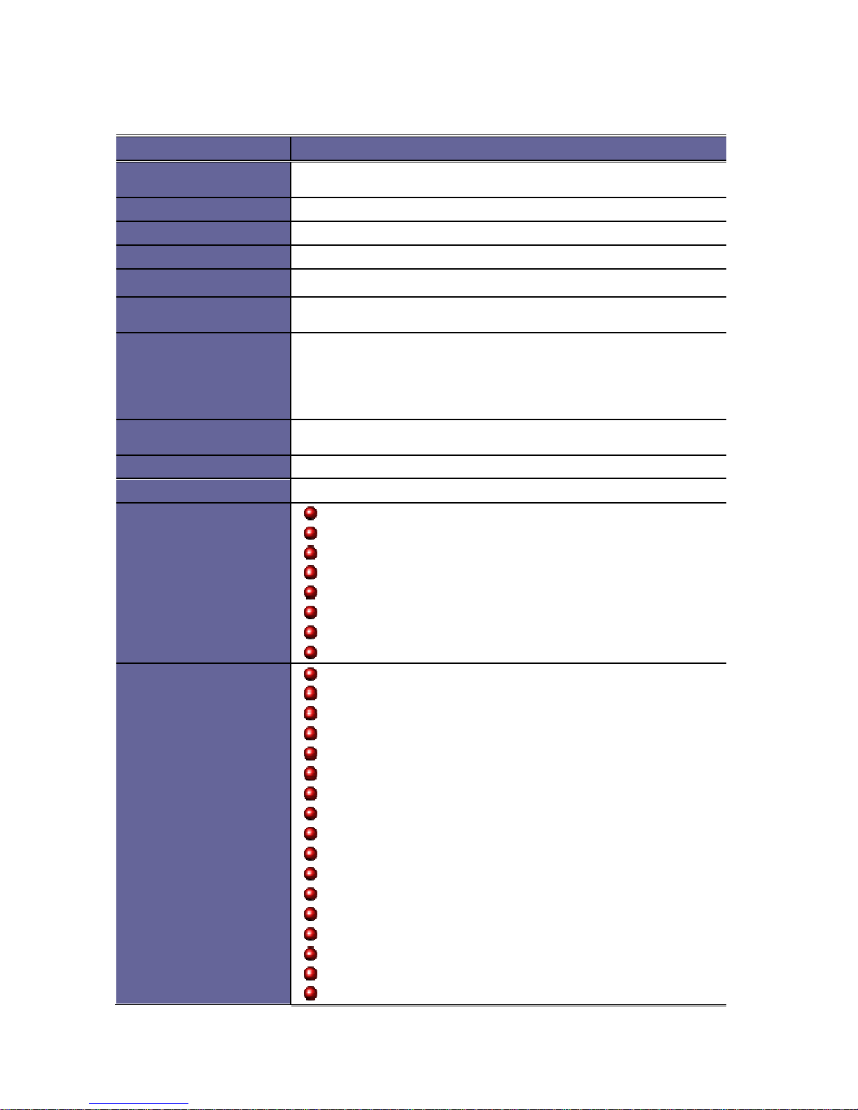
1.4 Specifications
Features VDX2-6526
CPU
DM&P SoC CPU Vortex86
DX2- 800MH z
Real T ime Clock w ith Lithium Battery B a ckup
Cache
L1:1 6K I-Cache, 16K D-Cache L2:256KB C a che
BIOS
AMI BIOS
Bus Interface
PC/1 04 Standard Complia nt
System Memory
512M B / 1 GB DDR2 Onboa rd
Watchdog Timer
Softwa re programm able fro m 30.5
us
to 512 se cond s x2
se ts(Watchdog 1 fully compatible with M6117 D)
VGA
In teg rated
2D VGA chip with dual display support (VGA + TTL /
VGA + LVDS)
VGA: Maximum resolutio n up to 1280x1024 @ 60 H z
LVDS : Maximum resolu tion up to 1024x768 @ 6 0 H z
Sin g le channel 24-bit LVDS
LAN
In teg rated 10/100M Ethernet
x1
Realte k 8111F 10/100/100 0 Mbps Ethernet x2
AUDIO
ALC 262 (HD Audio)
Touch Controller
PS/2 interface (Optio n al)
I /O Interface
SATA 7P Connector x 1
RS-2 32/485 port x4
Para l lel port x1
USB port x4 (USB 2 .0 version)
USB hot SWAP x 1 (O p tional)
16-b it GPIO port x1
10/1 00Mbps Ethernet port x1
10/1 00/1000 Mbps Eth e rnet port x2
Connectors
SA T A 7P for SATA x 1
2.00 mm ∅ 44-pin box heade r for LCD x 1
2.00 mm ∅ 26-pin box heade r for Printer x1
2.00 mm ∅ 20-pin box heade r for 16-bit G P IO x1
2.00 mm ∅ 20-pin header fo r LVDS x 1
2.00 mm ∅ 10-pin box heade r for VGA x1
2.00 mm ∅ 10-pin box heade r for USB x2
2.00 mm ∅ 10-pin box heade r for RS-232 x3
2.00 mm ∅ 8-pin header for Ethernet x 2
2.54 mm ∅ 4-pin header for DC -in x1
2.54 mm ∅ 2-pin header for Re set x1
1.25 mm ∅ 4-pin Wafer fo r Line-out/MIC-in x2
1.25 mm ∅ 4-pin Wafer fo r Touch screen x1 (Op tional)
Exte rnal RJ-45 connector for Ethernet x1
Exte rnal Mini DIN co nn e ctor for KBD/Mouse x1
Exte rnal D-Sub 15 pin female connector for V G A x1
Exte rnal D-Sub 9 pin male co nnector for R S 23 2 x1
Vortex86DX2-6526 Vortex86DX2 3.5” CPU Module
4
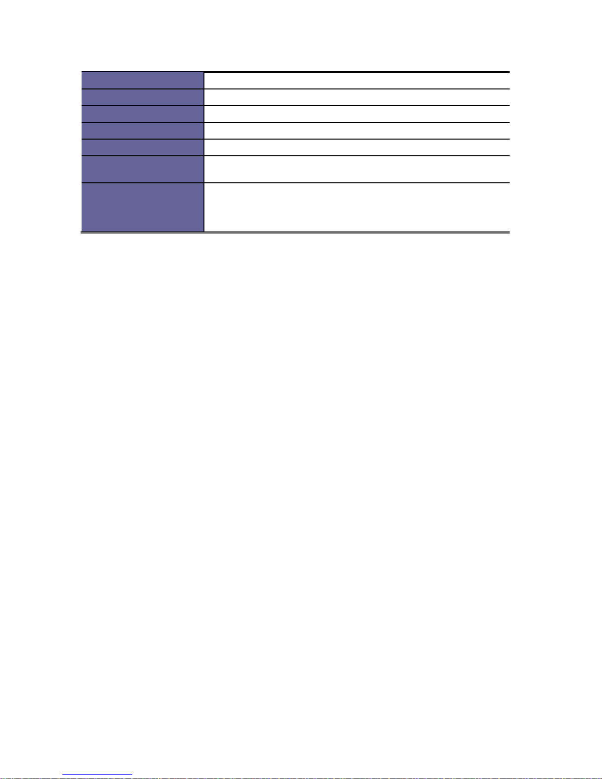
Flash Disk Support
Onbo a rd 4MB SPI Flash D i sk (Driver: A)
PWM
16 cha nnels
Power Requirement
Sin g le Voltage +5V @1 A
Dimension
102 X 146mm (4.01 x 5 .7 5 inches)
Weight
150g
Operating
Temperature
-1 0oC ~ +60oC
-4 0oC ~ +85oC (Optional)
Operating System
Support
Fre e DOS, DOS 6.22, PCDOS 7.1, DR
-
DOS, x
-
DOS, OD/2, CE6.0,
CE7.0 , Windows XP Pro fessional, Window s Embedded Standard
(X P E ), POS Ready(WePOS ), Embedded Linux, X-linux, QNX,
Vxw o rks and FreeBSD.

Vortex86DX2-6526 Vortex86DX2 3.5” CPU Module
5
1.5 Board Dimension
Vortex86DX2-6526 Vortex86DX2 3.5” CPU Module
6
C h a p t e r 2
Installation
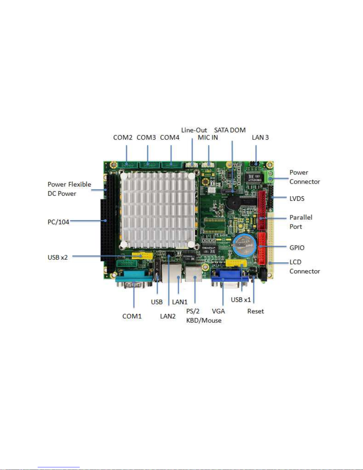
2.1 Board Outline
Note:
1. COM RS232/485 is selected by BIOS setting.
2. USB4 hot SWAP is optional. USB4 has no function if hot SWAP is not
selected.
3. Touchscreen is optional. No onboard SPI ROM and PS/2 mouse
functions if Touchscreen function is selected.
Vortex86DX2-6526 Vortex86DX2 3.5” CPU Module
7
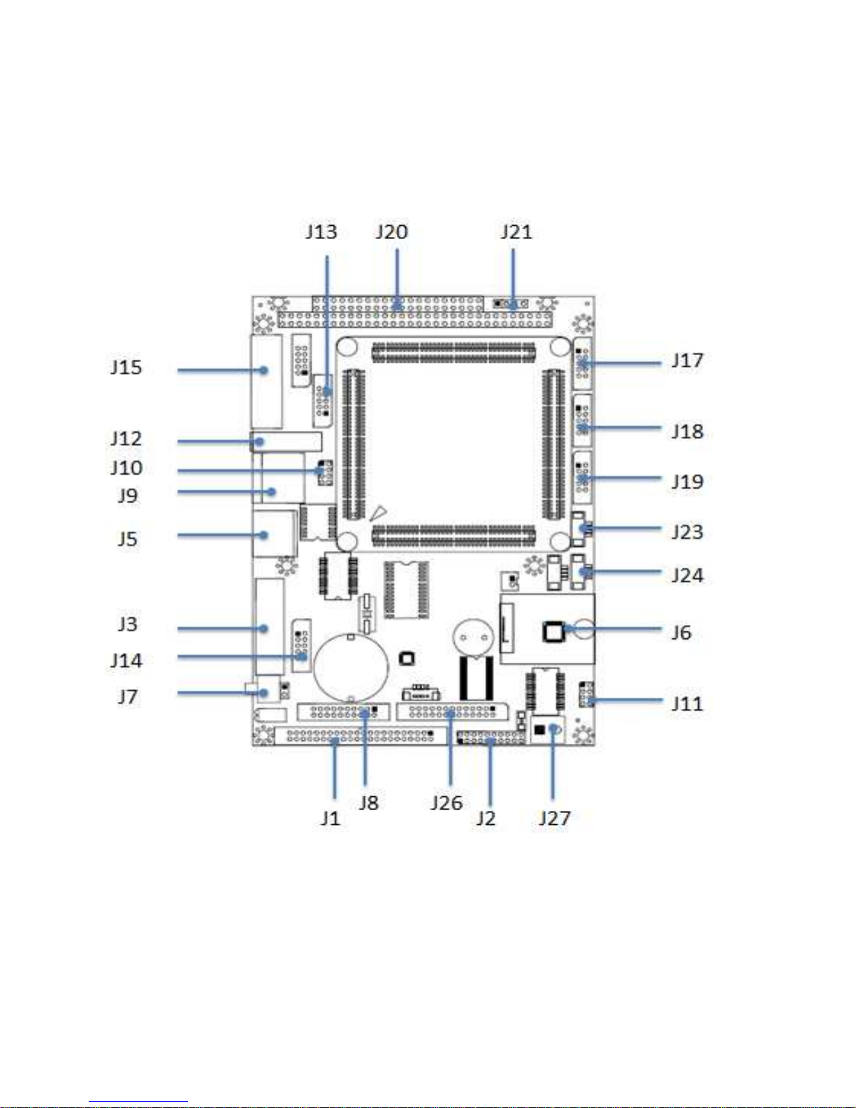
2.2 Connectors Location
Connectors
 Loading...