

ICOP PPC-104T User Manual
PPC-104T User’s Manual IUMPPC104T-01 Ver.1.0B Jun, 2016 i
User’s Manual
PPC-104T
DMP Vortex86 DX2 / DX3 Processor
Compact Panel PC with 10.4” Touchscreen
PPC-104T-D2 Series with DX2 processor
PPC-104T-D3 Series w ith DX3 processor
(Revision 1.0B)
PPC-104T User’s Manual IUMPPC104T-01 Ver.1.0B Jun, 2016 i
REVISION
DATE VERSION DESCRIPTION
2016/03/02 Version 1.0A New Release
2016/06/08 Version 1.0B Increase VDX3 solut i on
PPC-104T User’s Manual IUMPPC104T-01 Ver.1.0B Jun, 2016 ii
COPYRIGHT
The information in this manual is subject to change without notice for continuous
improvement in the product. All rights are reserved. The manufacturer assumes no
responsibility for any inaccuracies that may be contained in this document, and
makes no commitment to update or to keep current the information contained in this
manual.
No part of this manual may be reproduced, copied, translated or transmitted, in whole
or in part, in any form or by any means without the prior written permission of the
ICOP Technology Inc.
Copyright 2016 ICOP Technology Inc.
Manual # IUMPPC104T-01 Ver.1.0B Jun, 2016
TRADEMARKS ACKNOWLEDGMENT
Vortex86DX2 and Vortex86DX3 are the registered trademark of DMP Electronics
Inc. Other brand names or product names appearing in this document are the
properties and registered trademarks of their respective owners. All names
mentioned herewith are served for identification purpose only.
For more detailed information or if you ar e interested in other ICOP products, please
visit our official websites at:
Global: www.icop.com.tw
USA: www.icoptech.com
Japan: www.icop.co.jp
Europe: www.icoptech.eu
China: www.icop.com.cn
For technical support or demo images of operating systems download, please visi t
our websites at:
ICOP Technical Resource: http://tech.icop.com.tw/
Software Support: http://www.icoptech.net/
This Manual is for the PPC-104T.

PPC-104T User’s Manual IUMPPC104T-01 Ver.1.0B Jun, 2016 iii
SAFETY INFORMATION
Read these Safety instructions car ef ully.
Please carry the unit with bot h hands, handle carefully.
Make sure the voltage of the power source is correct before connecting the
equipment to the power outlet.
Do not expose your Panel PC to rain or moisture in order to prevent shock and
fire hazard.
Input voltage rated +12 ~ 24 VDC
Operating temperature between 0~+ 50° C (+32~+122°F).
Keep PPC-104T away from humidity.
When a Compact Flash Card or a SATA Slim is the main operating system
storage, please turn off power before inserting or removing. Do not open the
cabinet to avoid electrical shock. Refer to your nearest dealer for qualified
personnel servicing.
Never touch un-insulated terminals or wire unless your power adaptor is
disconnected.
Locate your Panel PC as close as possible to the socket outline for easy access
and to avoid force caused by entangling of your arms with surrounding cables
from the Panel PC.
USB connectors are not supplied with Lim it ed Power Sources.
If the equipment is not used for a long time, disconnect it from the power source
to avoid damage by transient overvoltage.
WARNING!
DO NOT ATTEMPT TO OPEN OR TO DISASSEMBLE THE CHASSIS (ENCASING)
OF THIS PRODUCT. PLEASE CONTACT YOUR DEALER FOR SERVICING FROM
QUALIFIED TECHNICIAN.

PPC-104T User’s Manual IUMPPC104T-01 Ver.1.0B Jun, 2016 iv
Content
Content ........................................................................................................................... iv
Ch. 1 General Information ................................................................................................ 1
1.1 Product Description ................................................................................................ 2
1.2 Product Specifications ............................................................................................ 3
1.3 Inspection standard for TFT-LCD Panel ................................................................. 5
1.4 Product Dimensions ................................................................................................ 8
1.5 Panel Mounting Instruction ................................................................................... 10
1.6 Ordering Information ............................................................................................. 12
Ch. 2 System Installation ................................................................................................ 13
2.1 CPU Board Outline ............................................................................................... 14
2.2 Connector Summary ............................................................................................. 15
2.3 Connector Pin Assignments .................................................................................. 16
2.4 External I/O Overview ........................................................................................... 18
2.5 External I/O Pin Assignment ................................................................................. 19
2.6 Watchdog Timer .................................................................................................... 20
Ch. 3 Hardware Installation ............................................................................................ 21
3.1 Installing the SATA Slim ........................................................................................ 22
3.2 Installing the Compact Flash ................................................................................ 24
Ch. 4 Driver Installation .................................................................................................. 25
4.1 PPC-104T Development Note .............................................................................. 27
4.2 BIOS Default Setting ............................................................................................. 28
4.3 Serial Ports Setting (RS232/422/485) ................................................................... 29
Ch. 5 Extension I/O (Optional) ....................................................................................... 36
5.1 Extension I/O Overview (Optional) ........................................................................ 37
5.2 Extension I/O Pin Assignment (Optional) .............................................................. 38
Warranty ......................................................................................................................... 39

PPC-104T User’s Manual IUMPPC104T-01 Ver.1.0B Jun, 2016 1
Ch. 1
General Information
1.1 Product Description
1.2 Product Specifications
1.3 Inspection standard for TFT-LCD Panel
1.4 Product Dimensions
1.5 Mounting Instruction
1.6 Ordering Information
PPC-104T User’s Manual IUMPPC104T-01 Ver.1.0B Jun, 2016 2
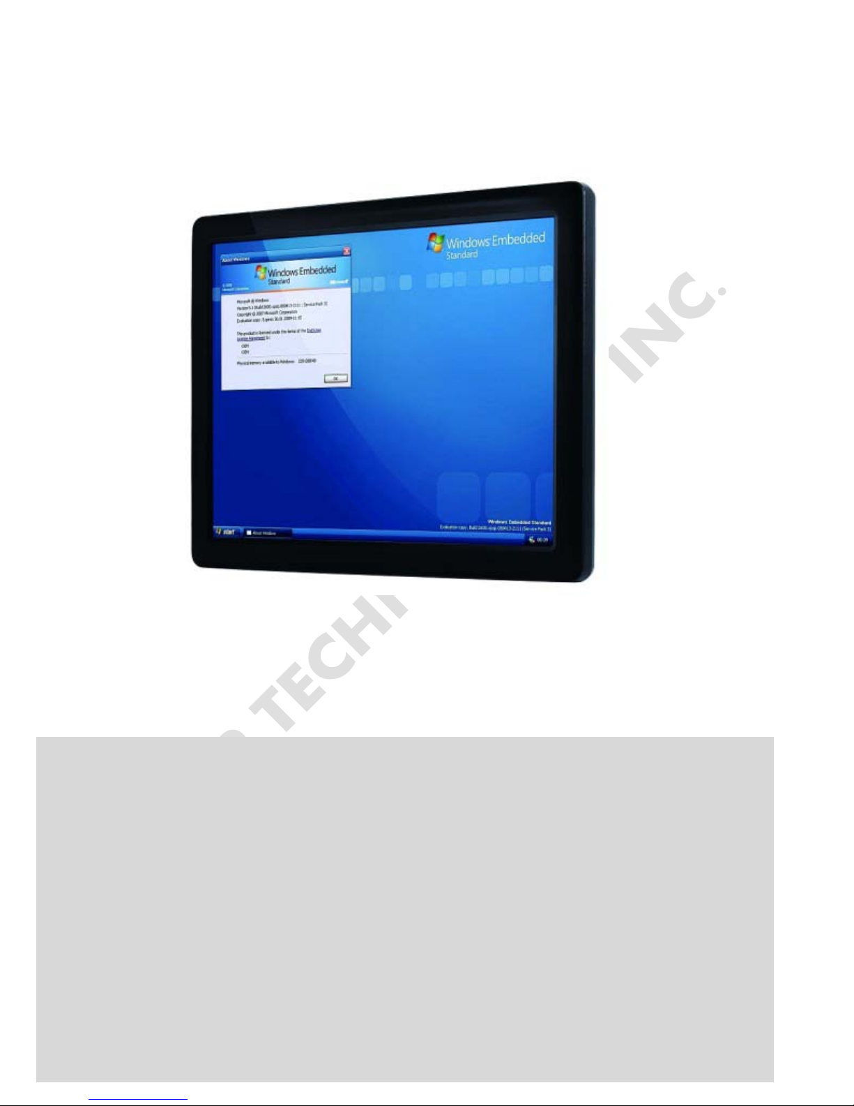
1.1 Product Description
ICOP Technology Inc. is proudly going to release a brand new Panel PC, which
offers fanless design, low power consumption, and IP65 front panel. The PPC-104T i s
powered by DMP’s latest Vortex86DX2 and DX3 SoCs, the 3rd generation SoCs of
Vortex86 family, and dual-channel 1GB / 2GB DDRII (DDRIII) chipset that handles
processing more efficiently and provides faster performance. The resistive touch panel
with LED backlight TFT LCD increases operation convenience and visibility in outdoor
environments. The ultra-compact and thin exterior design is perfect for the present
demanding embedded and productive applications.
The new PPC-104T inherited PDX/PMX-series’ smooth appearance and ultra-texture
aluminum exterior design to make your industrial applications look more stylish. The
versatile I/O ports, IP65 front panel, 10/100Mps Ethernet, GIGA high-speed Ethernet,
WLAN, etc. can fulfill fundamental functions. Our consistent advantages feature stable
performance, extended working temperature support, low power consumpt ion and fanless
design. The expandable customize I/O ports can be accommodated connectivity
requirements to industrial machine platforms and industrial automation equipment’s needs.
The PPC-104T supports Windows Embedded CE 6.0, Windows Embedded Compact 7,
Windows Embedded Standard 2009, Windows Embedded Standard 7 and Linux to meet
ready-to-market demand and provide competitive advantages for customers.
PPC-104T User’s Manual IUMPPC104T-01 Ver.1.0B Jun, 2016 3
1.2 Product Specifications
CPU BOARD SPECIFICATIONS
CPU DM&P Vortex86DX2- 933MHz / DX3-1GHz
Cache
DX2: L1:16KB I-Cache, 16KB D-Cache
L2: 256KB Cache
DX3: L1:32KB I-Cache, 32KB D-Cache
L2: 512KB Cache
BIOS AMI BIOS
Memory 512MB / 1GB / 2GB DDR2(DDR3) onboard
Watchdog T imer
Software Programmable from
30.5u to 512 seconds x 2 sets
LAN
Integrated 10/100M Ethernet X1
Giga Ethernet (Optional) X1
Audio HD Audio-Realtek ALC262 CODEC
Internal Drives
Compact Flash Type I / II Slot
SATA SLIM
SD Slot (Optional)
I/O
RS-232/422/485 x 2
USB Ports (Ver2.0) x 3
PS/2 KB
Audio-Out
RJ-45 Port x 1
GIGA Ethernet Port X 1 (Optional)
MECHANICAL & ENVIRONMENT
Power Requirement +12 ~ 24VDC
Power Consumption +24VDC@ 1A
Operating Temperature
0~+50°C (+32~+122°F) /
-20~+60°C (-4~+140°F; DX2 with 800MHz)
PPC-104T User’s Manual IUMPPC104T-01 Ver.1.0B Jun, 2016 4
Storage Temperature -30~+70°C (-22~ +158°F)
Operating Humidity 0% ~ 90% Relative Humidity, Non-Condensing
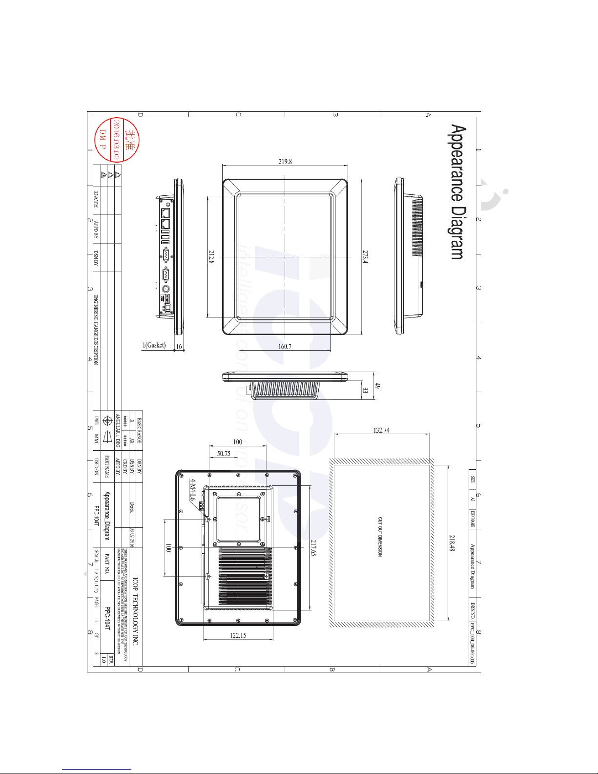
Dimensions 273.40x219.80x49mm (10.76"x8.65"x1.93")
Weight 1.75 Kg
Protection IP65 Front Panel
Certification CE / FCC / VCCI / Vibration / Shock
LCD SPECIFICATIONS
Display Type 10.4” SGA TFT LCD
Backlight Unit LED
Display Resolution 800(W) x 600(H)
Brightness (cd/m2) 500 nits
Contrast Ratio 500 : 1
Display Color 262,144
Pixel Pitch (mm) 0.264 (H) x 0.264 (V)
Viewing Angle Vertical 110o, Horizontal 140o
Backlight Lifetime 50,000 hrs
TOUCHSCREEN
Type Analog Resistive
Resolution Continuous
Transmittance 80%
Controller PS/2 interface
Software Driver Linux / WinCE / Windows XP
Durability 1 million
PPC-104T User’s Manual IUMPPC104T-01 Ver.1.0B Jun, 2016 5
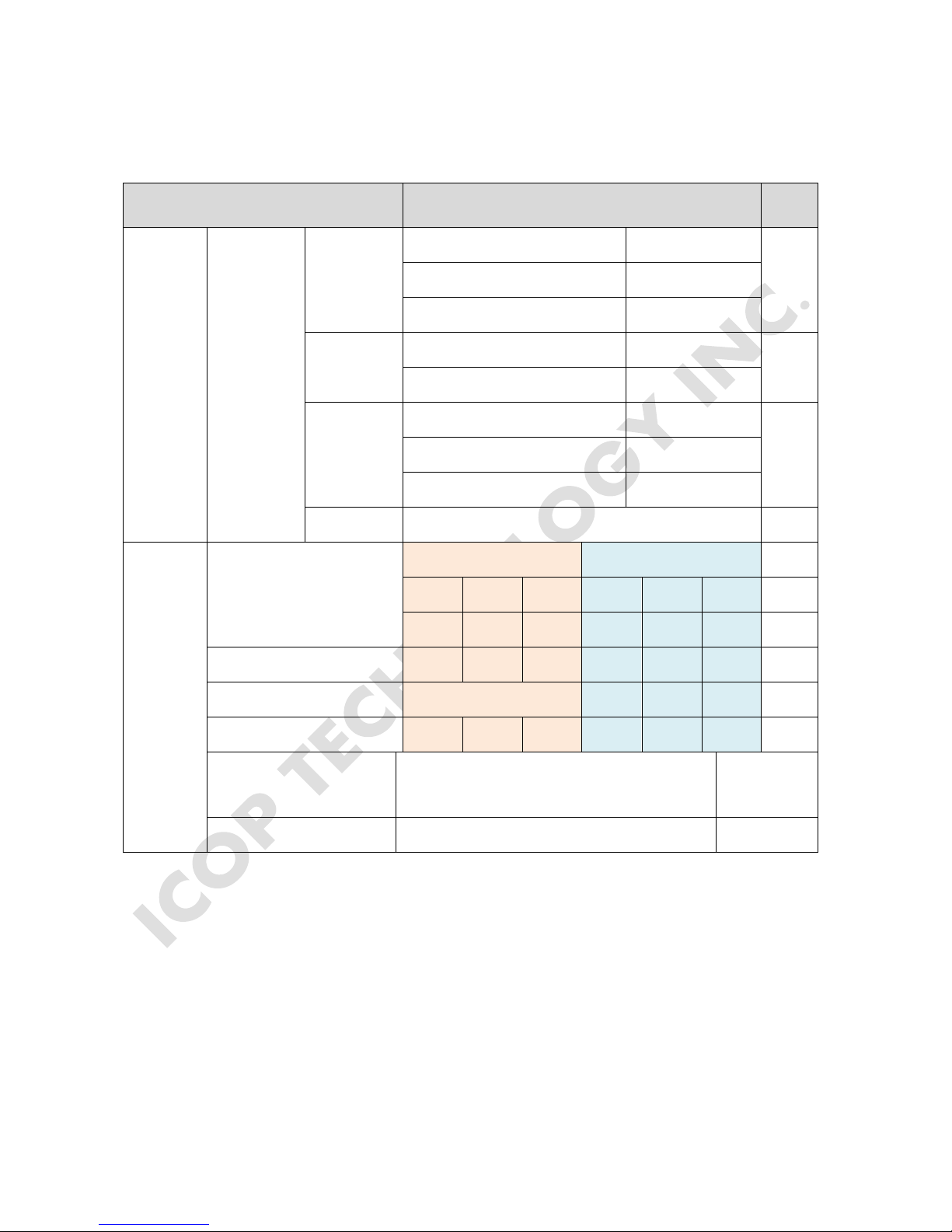
1.3 Inspection standard for TFT-LCD Panel
DEFECT TYPE LIMIT
Note
VISUAL
DEFECT
INTERNAL
SPOT
φ<0.15mm
Ignore
Note1
0.15mm≦φ≦0.5mm N≦4
0.5mm<φ
N=0
FIBER
0.03mm<W≦0.1mm, L≦5mm N≦3
Note1
1.0mm<W, 1.5mm<L
N=0
POLARIZER
BUBBLE
φ<0.15mm
Ignore
Note1
0.15mm≦φ≦0.5mm N≦2
0.5mm<φ
N=0
Mura It’ OK if mura is slight visible through 6%ND filter
ELECTRICA
L DEFECT
BRIGHT DOT
A Grade B Grade
C Area O Area Total C Area O Area Total
Note3
N≦0 N≦2 N≦2 N≦2 N≦3 N≦5
Note2
DARK DOT
N≦2 N≦3 N≦3 N≦3 N≦5 N≦8
TOTAL DOT
N≦4 N≦5 N≦6 N≦8
Note2
TWO ADJACENT DOT
N≦0 N≦1 pair N≦1 pair N≦1 pair N≦1 pair N≦1 pair
Note4
THREE OR MORE
ADJACENT DOT
NOT ALLOWED
LINE DEFECT NOT ALLOWED
(1) One pixel consists of 3 sub-pixels, including R, G, and B dot. (Sub-pixel = Dot)
(2) Little bright Dot acceptitable under 6% ND-Filter.
(3) If require G0 grand (Total dot N≦0), please contact region sales.
PPC-104T User’s Manual IUMPPC104T-01 Ver.1.0B Jun, 2016 6
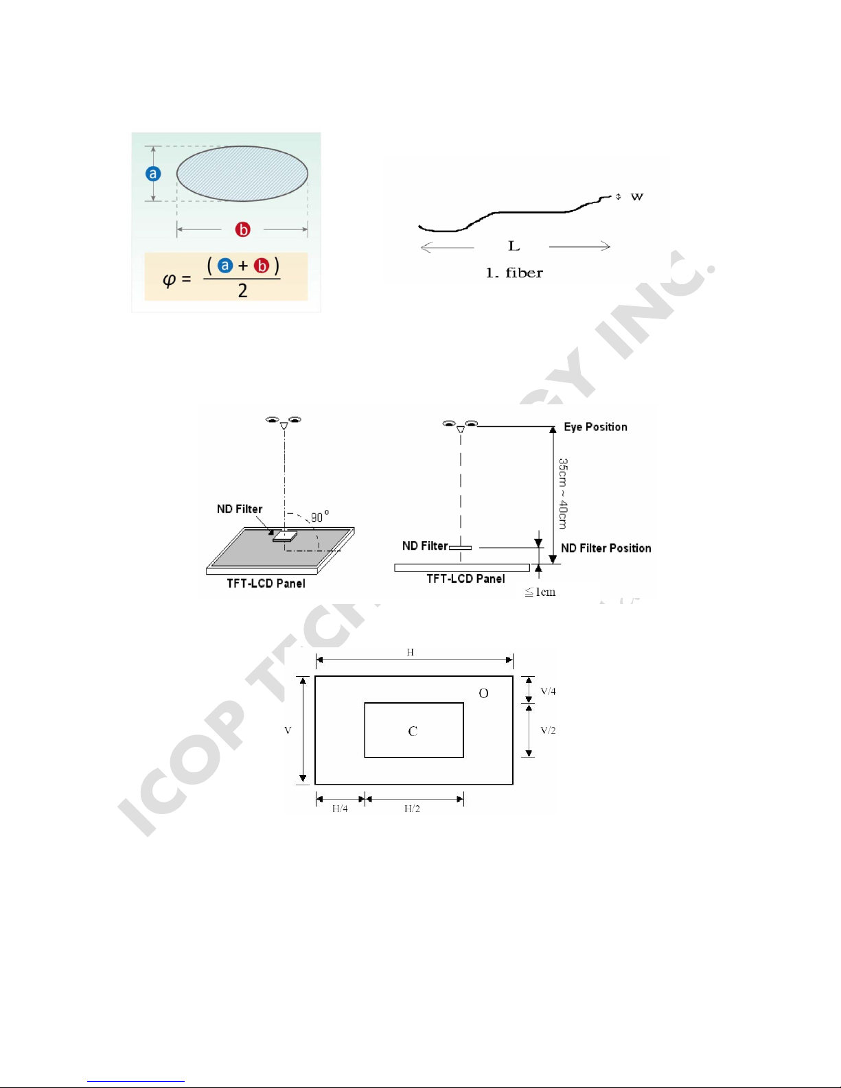
[ Note 1 ] W: Width[mm]; L: Length[mm]; N: Number; φ: Average Diameter.
(a) White / Black Spot (b) Polarizer Bubble
[ Note 2 ] Bright dot is defined through 6% transmission ND Filter as following.
[ Note 3 ] Display area
C Area: Center of display area O Area: Outer of di splay area
PPC-104T User’s Manual IUMPPC104T-01 Ver.1.0B Jun, 2016 7
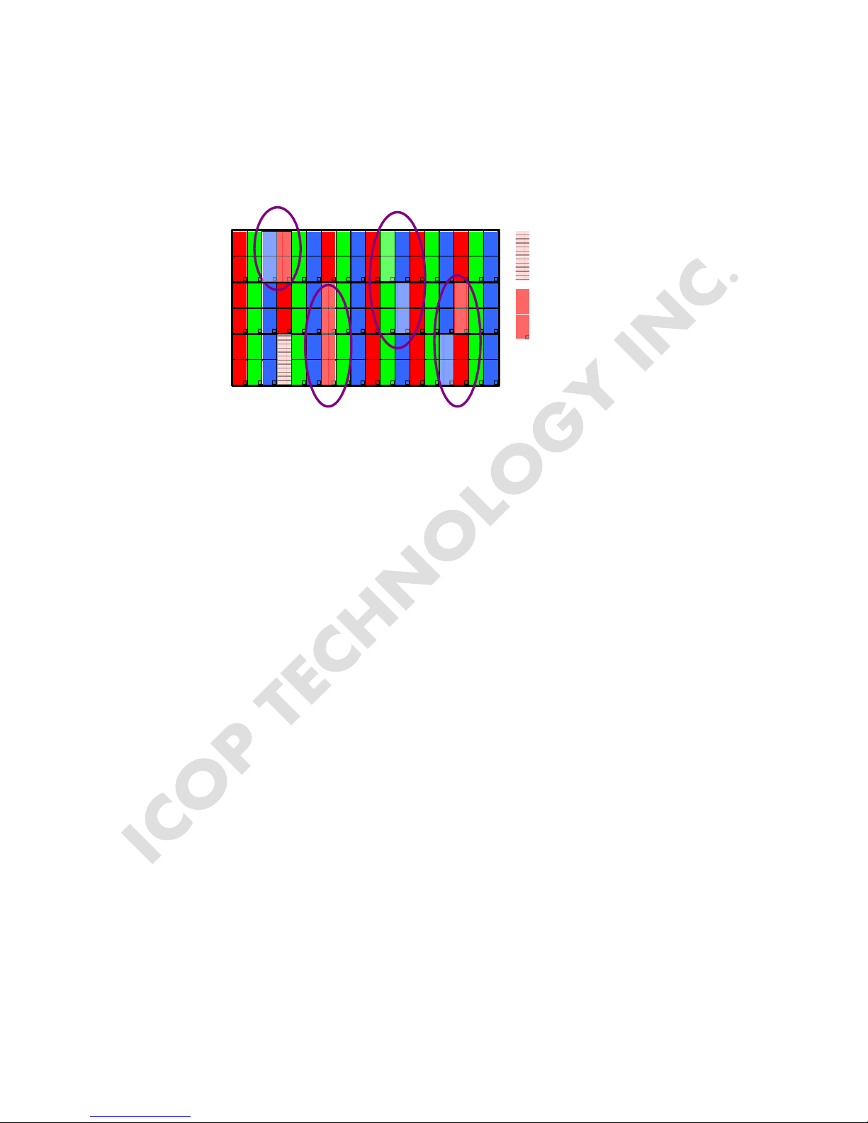
[ Note 4 ] Judge the defect dot and the adjacent dot as following. Allow below (as A, B, C and
D status) adjacent defect dots, including bright and dark adjacent dot. And they will be counted
2 defect dots in total quantity.
R
R
G
G
R
G
R
R
G
G
R
G
R
R
G
G
R
G
R
R
G
G
R
G
R
R
G
G
R
G
R
R
G
G
R
G
R
R
Defect Dot
Adjacent Dot
A
B
C
D
The defects that are not defined above and considered to be problem shall be reviewed
and discussed by both parties.
Defects on the Black Matrix, out of Display area, are not considered as a defect or counted.
PPC-104T User’s Manual IUMPPC104T-01 Ver.1.0B Jun, 2016 8
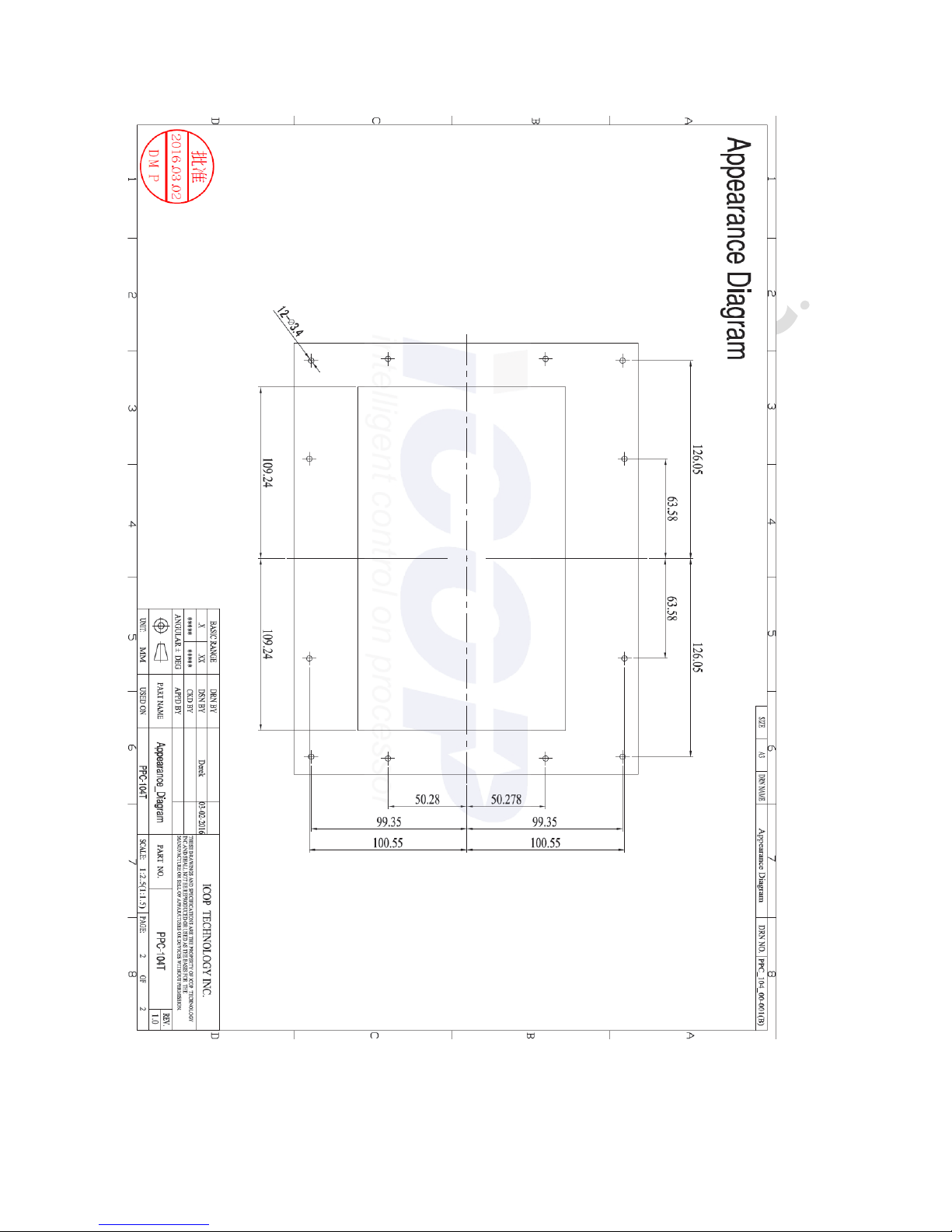
1.4 Product Dimensions
PPC-104T User’s Manual IUMPPC104T-01 Ver.1.0B Jun, 2016 9
 Loading...