

Page 1
1
1
Wireless Home Alarm
User Manual V2.1
Copy right© reserved
Page 2

2
2
1 Accessories ............................................................................................................................... 4
2 Introduction ............................................................................................................................. 5
2.1 Appearance ......................................................................................................................... 5
2.2 Specifications ...................................................................................................................... 5
2.3 Usage ................................................................................................................................... 6
2.4 LED Indicators Status ........................................................................................................... 6
3 Getting Start ............................................................................................................................. 7
3.1 Preparation .......................................................................................................................... 7
3.2 Installing the SIM Card, Battery, and Storage Card ............................................................. 7
3.3 Installation of device ......................................................................................................... 10
3.4 Battery Charging ................................................................................................................ 10
3.5 Setting Before Use ............................................................................................................. 10
4 Functions ................................................................................................................................ 10
4.1 Arm/Disarm ....................................................................................................................... 10
4.1.1 Manual Control ...................................................................................................... 10
4.1.2 SMS Control ............................................................................................................ 11
4.1.3 Dialing Control ........................................................................................................ 11
4.2 Timing Arm/Disarm ........................................................................................................... 11
4.3 Infrared Alarm ................................................................................................................... 12
4.4 MMS Notification .............................................................................................................. 12
4.5 SMS Notification ................................................................................................................ 13
4.6 Dialing Notification ............................................................................................................ 13
4.7 Power Disconnect Alert ..................................................................................................... 13
4.8 Low Battery Alert .............................................................................................................. 13
4.9 System Shut Down Alert .................................................................................................... 13
4.10 SD Card Failure Alert ....................................................................................................... 14
4.11 Voice Monitor .................................................................................................................. 14
4.12 Photograph ...................................................................................................................... 14
4.13 Service Platform .............................................................................................................. 14
5. Settings .................................................................................................................................. 15
5.1 Add SOS Number ....................................................................................................... 15
5.2 Delete SOS Number ................................................................................................... 15
5.3 Set APN ...................................................................................................................... 15
5.4 Set MMS .................................................................................................................... 15
5.5 Arm/Disarm ............................................................................................................... 15
5.6 Set Timing Arm .......................................................................................................... 16
5.7 Set Time Period of Timing Arm ................................................................................. 16
5.8 Set Time Zone ........................................................................................................... 16
5.9 Set MMS Notification ................................................................................................ 16
5.10 Set Resolution ......................................................................................................... 16
5.11 Set Number of Photograph ..................................................................................... 16
5.12 Set Alarm Capture ................................................................................................... 17
5.13 Set Time Interval of IR Alarm .................................................................................. 17
5.14 Set Dialing Notificaton ............................................................................................. 17
Page 3

3
3
5.15 LED Indicator Setting ............................................................................................... 17
5.16 Power Connect Notification Setting ........................................................................ 17
5.17 Power Disconnect Notification Setting .................................................................... 17
5.18 Server Setting .......................................................................................................... 18
5.19 Server with DNS service Setting .............................................................................. 18
5.20 Real-time Photograph Setting ................................................................................. 18
5.21 Check GPRSParameters ........................................................................................... 18
5.22 Check SET Parameters ............................................................................................. 19
5.23 Check Base Parameter ............................................................................................. 19
5.24 Check Firmware Version .......................................................................................... 19
5.25 Check Device Time .................................................................................................. 19
5.26 Reboot ..................................................................................................................... 20
5.27 Restore to Factory ................................................................................................... 20
5.28 Service Platform ...................................................................................................... 20
6.0 Appendix ........................................................................................................................... 20
6.1 Battery safety ............................................................................................................ 20
6.2 Troubleshooting ........................................................................................................ 21
Page 4

4
4
1 Accessories
Please make sure that all accessories are complete. Pictures are for indication and illustration
purposes only.
Page 5
5
5
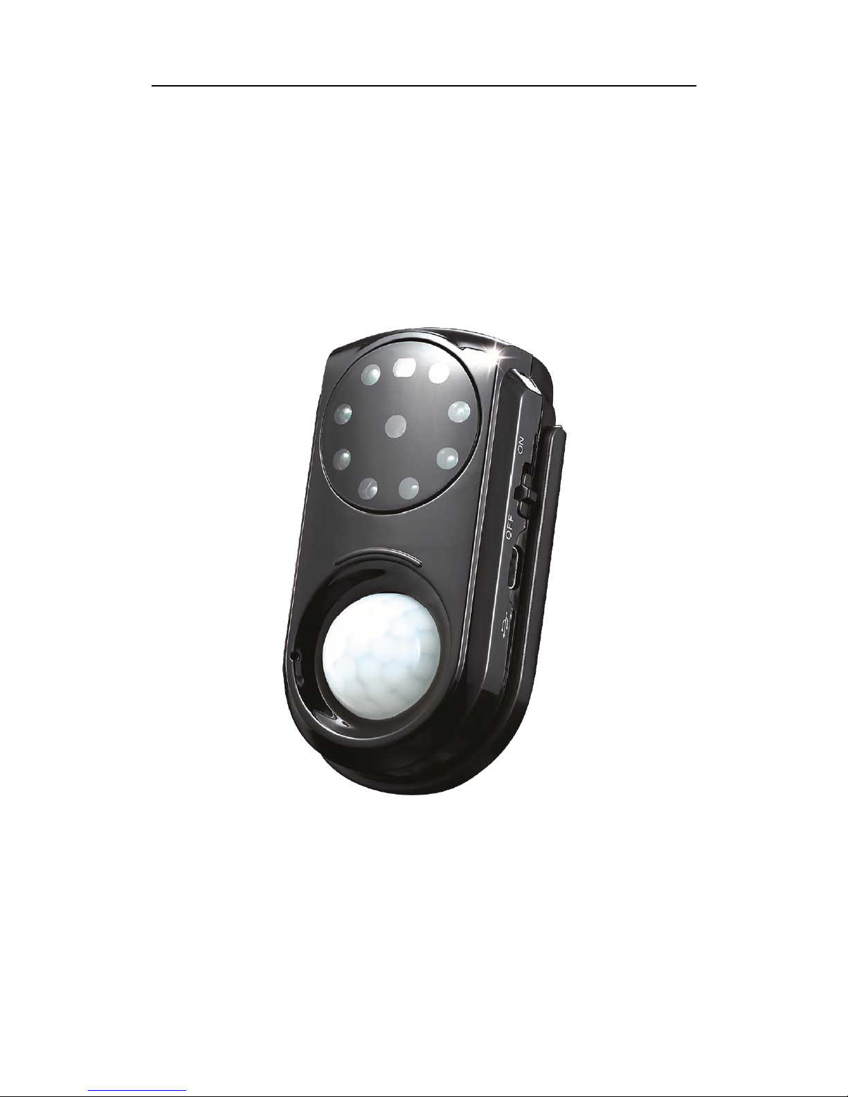
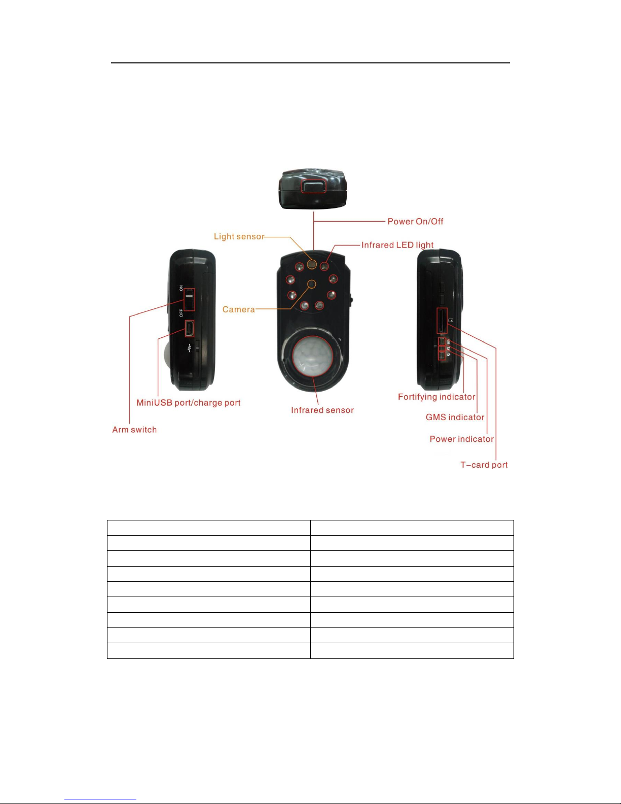
2 Introduction
2.1 Appearance
2.2 Specifications
GSM Frequency
GSM 850/900/1800/1900MHz
GPRS
Class 12
Image Resolution
640 X 480
Image Sensor
COMS 0.3 Mega Pixels
External storage
SD card, 2G (Maximum 4G)
Battery Capacity
800mAh
Working Voltage/Current
5V / 1A
Dimension
82.5mm(L)×44.3mm(W)×28.7mm(H)
Weight
61g
Page 6
6
6
2.3 Usage
2.4 LED Indicators Status
Red LED (Power/Working status)
Status
Implication
Quick flashing(interval 0.1s)
Low battery
Slow flashing(interval 1s)
Normal operating
Solid red
Battery charging
OFF
Battery power loss/Internal problem
Yellow LED(Arm/disarm status)
Status
Implication
Slow flashing(bright 0.1s,dark2s)
Delay arming
Slow flashing(bright 1s,dark1s)
Taking photo or recording video
Solid orange
Arming
OFF
Disarming
Quick flashing
Arm (10 seconds countdown)
Green LED(GSM signal)
Status
Implication
Quick flashing(interval 0.1s)
Searching (GSM Initialization)
Slow flashing(bright 0.1s dark 2s)
Normal operating
Solid green
GSM conversation/GPRS activation
OFF
No SIM card installed/No GSM signal
Notice: LED indicators have two modes:
1) Hidden Mode: All indictors would turn off automatically after working 5minutes till user
toggling Arm/Disarm switch button.
2) Continuously Bright Mode: indictors would never turn off if the device is working.
Page 7
7
7
3 Getting Start
3.1 Preparation
Please make sure all accessories are complete when open the package.
Please make sure the SIM card installed in device and:
a. Works with GPRS network
b. Works with MMS function
c. Works with SMS function
d. Works with Dialing function
e. Works with Caller ID function
3.2 Installing the SIM Card, Battery, and Storage Card
You need to remove the back cover before you can install the SIM card, battery, and storage card.
Also, make sure to always turn off the power before installing or replacing the SIM card and
battery.
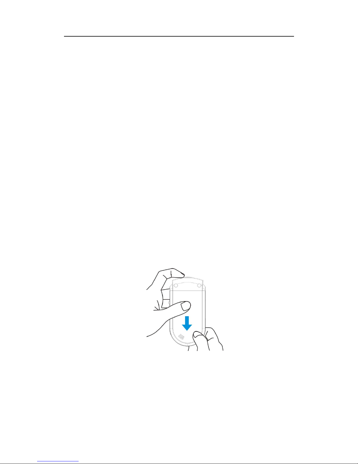
To remove the back cover:
Make sure your device is turned off.
Firmly hold the device with both hands and the front panel facing down.
Push the back cover up with your thumbs until it disengages from the device and then slide
it up to remove.
SIM Card
To install the SIM card:
Remove the battery if it is installed.
Locate the SIM card slot, then insert the SIM card with its gold contacts facing down and its
cut-off corner facing out the card slot.
Page 8

8
8
Slide the SIM card completely into the slot.
To remove the SIM card:
Remove the battery if it is installed.
Press and hold the lock in the SIM card slot opening with your thumb.
Slide the SIM card out from the slot with your other thumb or finger.
Note: Make sure there is enough credit on the SIM card. If you will be using the GPRS function,
you should pay attention to the current SIM card GPRS charge.
Battery
Your device comes with a rechargeable battery and is designed to use only
manufacturer-specified original batteries and accessories. Battery performance depends on many
factors, including network configuration, signal strength, and usage patterns. For more
information, see “Battery Safety” in the Appendix.
Warning!
To reduce risk of fire or burns:
Do not attempt to open, disassemble, or service the battery pack.
Do not crush, puncture, short external contacts, or dispose of in fire or water.
Do not expose to temperatures above 40°C.
Replace only with the battery pack designated for this product.
Recycle or dispose of used battery as stipulated by local regulations.
To install the battery:
Align the battery’s exposed copper contacts with the battery connectors at the bottom part
of the battery compartment.
Insert the contacts side of the battery first and then gently push the battery into place.
Replace the back cover.
Page 9

9
9
To remove the battery:
Make sure your device is turned off.
Remove the back cover.
The upper right side of the battery has a notch. Lift the battery by the notch to remove it.
Storage Card
To install a SD card:
Make sure that your device is turned off, and then remove the back cover.
Locate the SD card slot on the upper part of the exposed right panel.
Insert the SD card into the slot with its gold contacts facing down until it clicks into place.
To remove the SD card, press it to eject it from the slot.
Page 10

10
10
3.3 Installation of device
Fix the base with the bracket and keep the base rabbet upward.
Put the device on the base with the camera lenses facing forward and straightly to ensure
that the photos and videos are taken in right direction. Then fix the bracket on the wall or
other solid object.
Connect power for use.
3.4 Battery Charging
Make sure the charger is connected with power.
When device is charging, the red LED continually in bright state indicates battery is charging.
Slow flashing indicate power of battery is full. Quick flashing indicates low power and
charging need.
Battery charging should be operated under 0℃~40℃ with charger provided by the
manufacturer. Any unauthorized charger may result in danger and breach of approval and
warranty terms of this device.
Notice: Device would auto reboot after power recovery if the device is off by battery run out of
power.
3.5 Setting Before Use
Please add the SOS right before other settings.
If you get the SMS reply “NO Author”, that means the cellphone number you are using is not
the SOS number of device. In this case, please connect the device with your PC, and format
the removable disk with about 600k space, device will restored to factory setting. Reboot
the device and add the SOS number again. Or use the SOS number to add your phone
number as SOS number.
Please set the APN and MMS info right to use the GPRS network and MMS function, or the
device would auto reboot in 20 minutes because of failed to connect with the service
platform.
All operation details please refer to chapter 5.
4 Functions
4.1 Arm/Disarm
4.1.1 Manual Control
Toggle the Arm/Disarm switch button;
Page 11

11
11
If the device is in disarm status, toggle the ARM switch once to enter delay arming status
with the yellow LED indicator flashing. After 1minutes it enters arming status with the yellow
LED indicator continually lighting.
If the device is in arm status, toggle the ARM switch once to enter disarming status with the
yellow LED indicator off.
4.1.2 SMS Control
Arm by sending SMS command: “ON#”
SMS is replied to SOS number as: “Alarm fortification success!” in one minute
Disarm by sending SMS command: “OFF#”
SMS is replied to SOS number as: “Alarm disarm success” in one minute
4.1.3 Dialing Control
When the device is in disarming status, dial the device number from SOS phone and hang up
in 10 seconds, device would enter arming status automatically; If not, the device would
enter voice monitoring status.
When the device is in arming status, dial the device number from SOS phone and hang up in
10 seconds, the device would enter disarming status automatically; If not, the device would
enter voice monitoring status.
4.2 Timing Arm/Disarm
If you don’t need to monitor for 24 hours, please send the command to turn the timing arm
function as below:
1. Set the arm time period:
TIME, PERIOD1, PERIOD2, PERIOD3#
Format of Time period: HH:MM-HH:MM;
Example:
Set the first time period
TIME, 00:00-08:00#
Set the first and second time period
TIME, 00:00-08:00, 12:00-13:00#
2. Turn on the timing function via SMS command ”TIMEON#”
Send SMS command “TIMEOFF#” to turn the timing arm function off.
Note:
1. The device would synchronize time once each day with the server via GPRS, thus manually
setting time is not needed.
2. When entering arming time period, the device would automatically enter arming status
Page 12

12
12
from disarming status before.
4.3 Infrared Alarm
When device in “Armed” status, if motion detected, device would start to pictures and
record video, the alarm process as below:
a. Take pictures and video, storage in the SD card, user can review all details by connect
with PC.
b. If GPRS network works, all pictures would be uploaded to the service platform:
www.cootrack.com
c. If MMS function is ON, the first picture would be sent to the SOS phone number via
MMS; if not, alarm info would be sent via SMS.
d. If the storage space of SD card less than 10M, device would auto delete the files of first
alarm, including the pictures and video.
The number of picture capture and video record time can be customized via SMS
command:
ALARMSET, number of pictures, record time#
*Number of pictures: 0 ~ 5 (0 means no pictures when alarm is triggered)
Video record time: 0 ~ 300s (0 means not video recorded when alarm is triggered)
Factory setting is: “ALARMSET,3,60#”
The default time interval of two alarm events is300 seconds, which mean the after first
alarm, the second alarm would not be triggered in 5 minutes. Time interval can be change
via SMS command:
INTERVAL, time# (time arrange: 60 ~3600 s)
4.4 MMS Notification
To use MMS notification, please set the MMS parameters via SMS command:
MMS, urlOfmmsc,IP,Port ,APN,user, pwd,ConnectType#OR
MMS, urlOfmmsc l,IP,Port,APN#
MMS notification can be ON or OFF by SMS command: MMSON# or MMSOFF#. Factory
status is OFF.
If MMS function is ON, the first picture would be sent to SOS number via MMS as below
format when the alarm is triggered:
Page 13

13
13
4.5 SMS Notification
If MMS notification is OFF, device would send SMS notification to SOS number with
message” Alarm” when the alarm is triggered.
4.6 Dialing Notification
When alarm is triggered, device can auto dialing to the SOS numbers, user can monitor the
live voice after pick up the call. Factory status is OFF.
4.7 Power Disconnect Alert
Alarm message “Main power is interrupted, please pay attention!” would be sent to SOS
numbers via SMS if the power is disconnect/fail.
If device is ON, when power is connect again, alarm message “Main power connection has
been restored!” would be sent to SOS numbers via SMS. Factory status is OFF.
4.8 Low Battery Alert
Alarm message “Alarm battery voltage is low, please charge in time!” would be sent to SOS
numbers if the inside battery voltage is under 3.7V.
4.9 System Shut Down Alert
Alarm message “System shutdown!” would be sent to SOS number via SMS when the system
Page 14

14
14
is going to shut down because of the voltage of battery is lower than 3.5V
4.10 SD Card Failure Alert
Alarm message “Alarm memory card detection failed, please make sure that the memory
card is inserted, or the card space is available!” would be sent to SOS numbers if device
cannot detect the SD card.
4.11 Voice Monitor
SOS number can monitor the live voice of device; it would pick up the call after 10s and into
the voice monitor status.
If there is alarm trigger when monitoring the voice, device would hang up the call and
handle the alarm information first.
4.12 Photograph
SOS number can take the real time picture via SMS command “PHOTO# ” or “333”, pictures
would be sent to SOS number via MMS.
4.13 Service Platform
www.cootrack.com is design for device online management; provides multiple functions
such like pictures review, Arm/Disarm, SOS number setting, timing alarm setting, etc.
Please log in with:
Account: IMEI number of the device
Password: 666666(Default)
* Make sure the APN setting is right to use the GPRS network.
Users can send message to turn on or close service platform:
Turn on service platform:“GPRSON,1#”;
Close service platform: “GPRSON,0#”.
Page 15

15
15
5. Settings
5.1 Add SOS Number
Command
Reply SMS
Description
SOS,A,P1,P2,P3#
SOS1:688361
SOS2:688362
SOS3:688363
(eg)sos,a,688361,688362,688363#
5.2 Delete SOS Number
Command
Reply SMS
Description
(a)SOS,D,1[,2[,3]]#
(b)SOS,D,P1,P2,P3#
SOS1:
SOS2:
SOS3:
Sos,d,1# means delete the
first SOS number;
Sos,d,688361,688362#
means delete SOS number
688361, 688362
(ega)sos,d,1,2#
(egb)sos,d,688361,688362 #
5.3 Set APN
Command
Reply SMS
Description
(a)APN,apnname#
(b)APN,apnname,user,pwd#
Set Success
(ega)apn,kktcell#
(egb)apn,orange,orange,orange#
5.4 Set MMS
Command
Reply SMS
Description
(a)MMS,centerAddress,IP,Port ,APN,user,
pwd,ConnectType#
(b)MMS,centerAddress,IP,Port,APN#
Set Success
Connect Type:
0: HTTP 1: WAP
Device reboot after
30seconds
(ega)mms,http://mms.orange.fr,192.168.
010.200,8080,orange,orange,1#
(egb)mms,http://mms.kktcell.com/cmms
c/post,212.252.169.99,8080,mms.kktcell#
5.5 Arm/Disarm
SMS Content
Reply SMS
Description
ON#
Alarm fortification success!
OFF#
Alarm disarm success!
Page 16

16
16
5.6 Set Timing Arm
SMS Content
Reply SMS
Description
TIMEON#
Timing fortification status: ON
ON timing alarm
TIMEOFF#
Timing fortification status: OFF
OFF timing alarm
5.7 Set Time Period of Timing Arm
SMS Content
Reply SMS
Description
TIME,S1,S2,S3#
Status: Off
Timing fortification status: Off
Fortification time: S1,S2,S3
Device current time:
2012-10-21;18:20:32
Format of Time period:
HH:MM-HH:MM;
TIME,08:00-12:00# set
the first time period as
8:00 to 12:00
(eg)TIME,08:00-12:00,14:0
0-15:20,23:00-24:00#
5.8 Set Time Zone
SMS Content
Reply SMS
Description
(a)GMT, time bearing, time
zone#
(b)GMT, time bearing,
time zone, half time zone#
Time zone:E,8,0
Timezone:E/W;
Standard Timezone:1-12;
Half-hour Timezone:15/30/45
(ega)GMT,E,8#
(egb)GMT,E,8,30#
5.9 Set MMS Notification
SMS Content
Reply SMS
Description
MMSON#
MMS alarm: ON
ON MMS notification
MMSOFF#
MMS alarm: OFF
OFF notification
5.10 Set Resolution
SMS Content
Reply SMS
Description
SIZE,1#
Photo resolution: 640*480
Set resolution as 640*480
SIZE,0#
Photo resolution: 320*240
Set resolution as 320*240
5.11 Set Number of Photograph
SMS Content
Reply SMS
Description
PHOTOSET,timeinterval,num of
picture#
Set Success
Time interval:0-60;
0:continuous shooting
Num of picture: 1-5
Factory status:
“PHOTOSET,0,1#”
(eg)PHOTOSET,0,1#
Page 17

17
17
5.12 Set Alarm Capture
SMS Content
Reply SMS
Description
ALARMSET,number of
picture,video record time#
Set Success
Number of pictures: 0-5,
video record time:0-300(s),
if 0, no photo or no video
record;
Factory:“ALAEMSET,3,60#”.
(eg)ALARMSET,3,60#
5.13 Set Time Interval of IR Alarm
SMS Content
Reply SMS
Description
INTERVAL,time#
Set Success
Time: 60-3600(s),
Factory:“INTERVAL,300#”
(eg)INTERVAL,300#
5.14 Set Dialing Notificaton
SMS Content
Reply SMS
Description
CALLSET,call time#
Set Success
Time: 0-3, 0 means off dialing
notification
Factory: “CALLSET,0#”
(eg)CALLSET,3#
5.15 LED Indicator Setting
SMS Content
Reply SMS
Description
HIDE,1#
Set Success
LED indicators will be off
after 5mins
HIDE,0#
Set Success
LED indictors always on
5.16 Power Connect Notification Setting
SMS Content
Reply SMS
Description
CHARGERIN,ON#
Set Success
CHARGERIN,OFF#
Set Success
5.17 Power Disconnect Notification Setting
SMS Content
Reply SMS
Description
CHARGEROUT,ON#
Set Success
CHARGEROUT,OFF#
Set Success
Page 18

18
18
5.18 Server Setting
SMS Content
Reply SMS
Description
(a)SERVER,1,domain,port,0#
(b)SERVER,0,ip,port,0#
Set Success
(ega)SERVER,1,coomix.goomegps.net,9880,
0#
(egb)SERVER,0,183.60.142.140,0#
5.19 Server with DNS service Setting
SMS Content
Reply SMS
Description
(a)DSERVER,MODE1,domain,port,protocol0
#
(b)DSERVER,mode0,IP,port,protocol0#
Set Success
(ega)DSERVER,1,www.ydpat.com,8011,0#
(egb)DSERVER,0,211.154.135.113,8011,0#
5.20 Real-time Photograph Setting
SMS Content
Reply SMS
Description
(a)PHOTO#
(b)333
MMS with pictures
5.21 Check GPRSParameters
SMS Content
Reply SMS
Description
GPRSSET#
GPRS APN:internet.kktcell
GPRS name:
GPRS pwd:
MMS
URL:http://mms.kktcell.com/cmmsc
/post
MMS IP: 212.252.169.99
MMS port:8080
MMS APN:mms.kktcell
MMS name:
MMS pwd:
MMS type:
SERVICE SET:
url:coomix.goomegps.net
mod:0
addr:0.0.0.0
port:9880
protol_type:0
Page 19

19
19
5.22 Check SET Parameters
SMS Content
Reply SMS
Description
(a)SET#
(b)555
Status: OFF
SOS1: 123456
SOS2:
SOS3:
Timing fortification status: OFF
Fortification
time00:00-23:59,00:00-00:00,00:00
-00:00
Device current
time:2012-12-18;8:35:52
IMEI: xxxxxxxxxxxxxxx
MI number:1544863
MMS alarm:ON
Photo resolution:320*240
5.23 Check Base Parameter
SMS Content
Reply SMS
Description
PARAM#
BY:NORMAL;GPRS: Link Up;GSM:
Strong;GN:1;GT:E,8;LG:0;SE:0;AT:3,60;PT
:1;CT:0;IL:300;CO:ON;CI:OFF;HE:1;
Battery status, GPRS
status,GSM status, server
status,time
zone,language,resolution,IR
alarm
status,photographsetting,dia
ling notification status,IR
alarm time interval,power
failure alarm status,power
connect alarm status,LED
indicator setting.
5.24 Check Firmware Version
SMS Content
Reply SMS
Description
VERSION#
[VERSION:]GM01_30_3SP_V20_WM
[BRANCH:]09A_V20 GXQ53_12832_09A
5.25 Check Device Time
SMS Content
Reply SMS
Description
SETTIME#
Alarm current time is:
2012-10-21;18:20:32
Page 20

20
20
5.26 Reboot
SMS Content
Reply SMS
Description
RESET#
system reboot after 30 seconds
Device would reboot in 30s
5.27 Restore to Factory
SMS Content
Reply SMS
Description
FACTORY#
Set Success, system reboot after 30
seconds
Restore to factory setting.
Device would auto reboot in
30s
5.28 Service Platform
SMS Content
Reply SMS
Description
GPRSON,1#
Set Success
Turn on service platform.
GPRSON,0#
Set Success
Close service platform.
6.0 Appendix
6.1 Battery safety
Please use the battery provided by the manufacturer of the device. Use of other accessories
may lead to void warranty service. The manufacturer is not liable for any damage resulted
from using accessories from other channels.
New battery should be fully charged (12 hours) and discharged for two or three times to
achieve the best performance.
Battery can be charged and discharged for hundreds of times and finally get useless. When
calling time and standby time is decreased obviously, you need to change new battery.
Touching any metal object (key in pocket) would easily cause battery short-circuit.
Do not forcibly bend and open battery.
Keep the battery away from water and fire.
Battery should be charged at room temperature. If temperature is lower than 0℃ or higher
than 40℃, the battery may not be charged.
Page 21

21
21
6.2 Troubleshooting
If you are having trouble with your mobile device, try these troubleshooting procedures before
contacting a service professional.
Common
problems
Causes
Solution
Fail to turn on
Power off
Charge battery
Fail to monitor
The called number is not the SOS
number
Set up SOS number
SIM card without caller ID display
function
Active function of caller ID display
Fail to connect
network
Wrong installation of SIM card
Check SIM card installation
Filth on the SIM card iron
surface.
Clean it
Useless SIM
Contact internet service provider
Beyond GSM service area
Use it in effective GSM service
offer area
Bad signal
Try again in a better signal area
Fail to
charge
The voltage is unsuitable
Connect with power with suitable
voltage
Improper connection
Check connection with charger
 Loading...