

Page 1
User manual
10-In / 8-Out with +48V Phantom Power
Recording USB Interface
Page 2
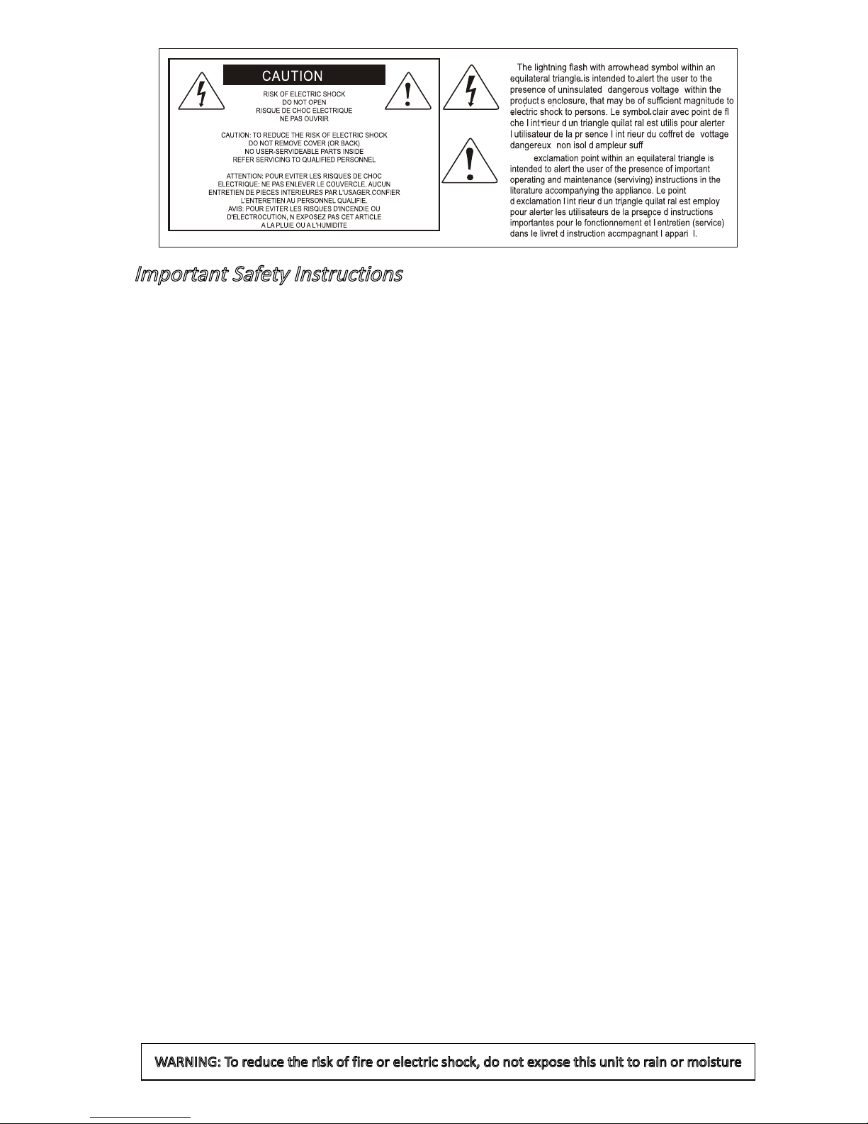
Important Safety Instructions
1. Read this manual thoroughly before using this unit.
2. Keep this manual for future reference.
3. Take notice of and comply with all warnings included in the user's manual or indicated on the
appliance.
4. Follow all instructions included in this manual.
5. Do not expose this unit to rain or moisture. Avoid having water or other liquids spilled on this
unit.
6. When cleaning the cabinet or other parts of this appliance, use only a dry or slightly damp soft
cloth.
7. Do not block any ventilation openings or interfere with the proper ventilation of this unit. Install
in accordance with the manufacturer's instructions.
8. Do not use or store near any heat sources such as radiators, heat registers, stoves, or other heat producing appliances.
9. Do not interfere with the safety purpose of the polarized or grounding-type plug. A polarized plug
has two blades with one wider than the other. A grounding-type plug has two blades and a third
grounding prong. These are designated for your safety. If the provided plug does not fit into your
outlet, consult an electrician.
10. Protect the power cord from being walked on or otherwise damaged by items placed on or
against them. Particular attention should be given to the plugs, receptacles, and the point where
the cord exits the appliance.
11. To avoid the risk of electrical shock, do not touch any exposed wiring while the unit is in
operation.
12. Only use attachments/accessories specified by the manufacturer.
13. Unplug this unit and all connected electrical equipment during lightning storms or when left
unused a long period of time.
14. Refer all servicing to qualified service personnel. Servicing is required when the appliance has
been damaged in any way or fails to operate normally.
WARNING: To reduce the risk of fire or electric shock, do not expose this unit to rain or moisture
Page 3

Introduction ............................................................................................... 4
What’s in the package? ............................................................................4
Features ...................................................................................................5
Front Panel ...............................................................................................6
Rear Panel................................................................................................8
Mac driver installation ............................................................................. 10
Mixer control panel .................................................................................12
Windows driver installation ..................................................................... 14
ProDriver VST ........................................................................................17
Mixer control panel .................................................................................18
Settings (Sample rate and latency settings) ........................................... 21
ProDriver VST hosting rack ....................................................................25
Hardware Connections ........................................................................... 26
Specications .........................................................................................27
Services .................................................................................................. 28
Contents
Page 4

4
Introduction
What’s in the package?
Please write your serial number here for future reference:
Purchased at:
Date of purchase:
● Umix1008Rack-VST USB Recording Interface
● Quick Start Guide x 1
● Driver Software CD with Electronic user manual & quick start guide (pdf)
● DAW software – Reaper & KiloHearts VST
● USB 2.0 cable x 1
Thank you for purchasing the ICON Umix1008Rack-VST digital audio Interface. We
sincerely trust this product will provide years of satisfactory service, but if anything is
not to your complete satisfaction, we will endeavor to make things right.
In these pages, you'll nd a detailed description of the features of the Umix1008Rack-
VST digital audio interface, as well as a guided tour through its front and rear panels,
step-by-step instructions for its setup and use, and full specications.
You'll also nd a warranty card enclosed---please don't forget to ll it out and mail
it in, or register your product online at: www.iconproaudio.com, for the most
effective technical support, and so we can send you updated information about this
and other ICON products in the future. As with most electronic devices, we strongly
recommend you retain the original packaging. In the unlikely event the product
must be returned for servicing, the original packaging (or reasonable equivalent) is
required.
With proper care and adequate air circulation, your Umix1008Rack-VST digital audio
interface will operate without any trouble for many years. We recommend that you
record your serial number in the space provided below for future reference.
Page 5

5
Features
● 24-Bit 192KHz 10-In/8-Out USB Recording Interface
● High dynamic range:
DAC: Dynamic Range: 114dB
ADC: Dynamic Range: 114dB
● 8 x 6 analog I/O full duplex recording and playback
● 8 x Mic/Instrument preamps with individual gain control and phantom power switch
● 6 analog outputs on 1/4” TRS jacks
● S/PDIF I/O on RCA coaxial connectors
● 1 x 1 – 16 channel MIDI I/O
● Master volume control on the front panel
● 2 headphone outputs with assignable source and individual volume control
● Flexible channel routing via the software control panel
● ICON's innovative ProDriverVST™ VST plug-ins hosting rack is provided
● Kilohearts VST plug-ins are provided
● USB2.0 High Speed equipped and USB bus-powered
● Supports DirectSound, WDM and ASIO2.0
● Compatible with Mac OS (Intel-Mac) 10.11 and later, iOS 9 or above and Windows 7,
8 & 10 (32-bit/64-bit)
● Full duplex, simultaneous record/playback
● +12VDC power supply connector is equipped for external power supply when using
with iOS
● Rugged aluminum construction
The ICON Umix1008Rack-VST USB recording interface provides an audio input and
output module with USB connectivity. Main features include:
Page 6
6
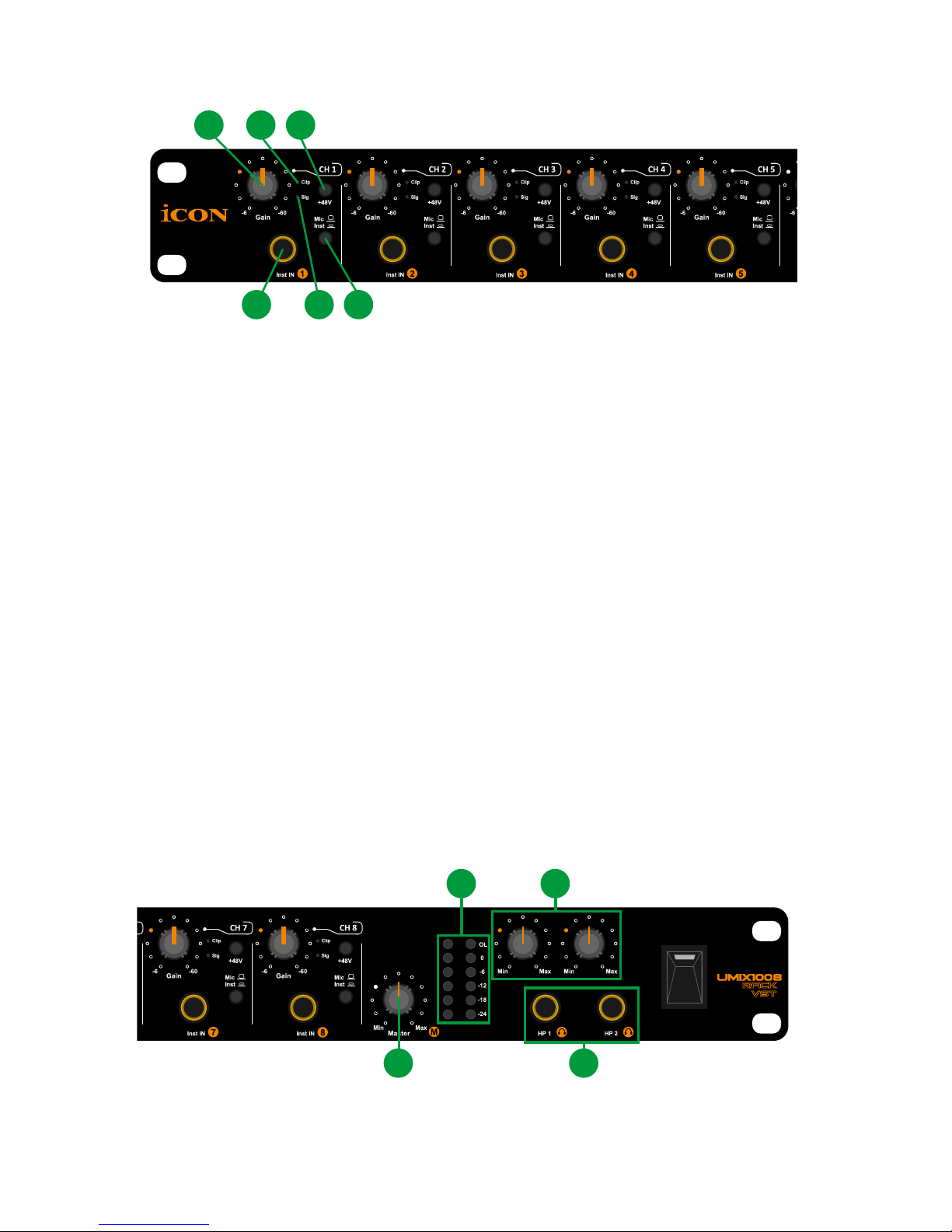
Front Panel
1. HI-Z input
This is a high impedance input for guitar/bass.
2. “Inst/MIC” input switch
Mic or MIC input switch for input 1-8.
3. Input gain level controls 1-8
These potentiometers control the input level of their associated analog Mic/Inst/
Line input.
4. 48V phantom power switch
Press to supply +48V phantom power to the associated XLR (Rear panel) input.
This phantom power circuit is suitable for most condenser microphones.
5. Sig (Signal LED indicator)
When lit, this LED indicates the presence of an audio signal at the associated
MIC/INST input.
6. Clip (Clip LED indicator)
When lit, this LED indicates clipping input level at the associated MIC/INST
input. The LED will illuminate when the signal is 3dB below the clipping point.
1
3 6 4
25
8 9
7
10
7. Master level control
This potentiometer controls the master output level (output Ch.1-2) of the analog
outputs.
Page 7

7
8. Output level metering
Showing the output level for the master channel.
9. Headphone level control 1-2
These potentiometers control the output level of the associated headphone
output.
10. Headphone output 1-2
These output jacks accept a standard 1/4″ stereo TRS headphone connector.
Page 8
8
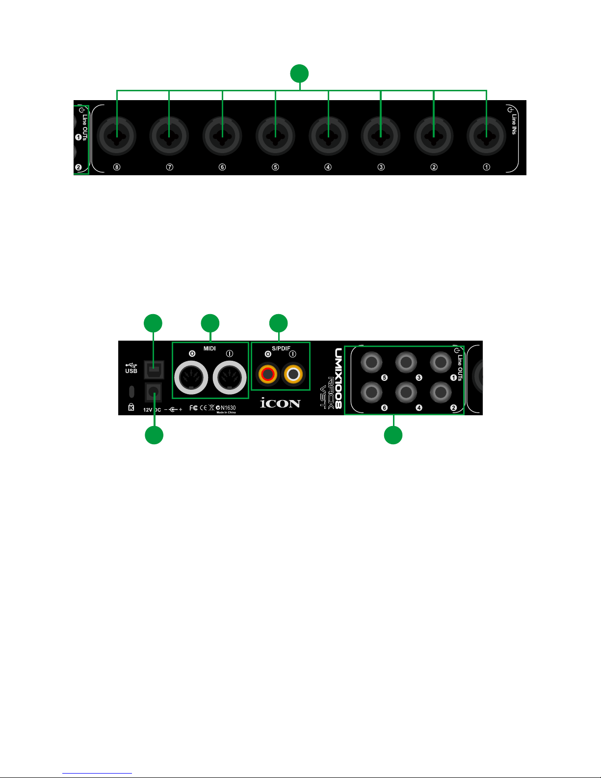
Rear Panel
1. Mic/Line” inputs 1-8
Balanced mic/Line level inputs. These hybrid connectors will accept a
standard 3-pin XLR plug or a 1/4” TS connector.
1
2
3
1
45
6
2. Line outputs 1-6
These are balanced analog outputs on standard 1/4″ TS connectors at +6dBU
line level.
3. S/PDIF coaxial I/O connectors
S/PDIF digital input and output on coaxial RCA connectors. The digital input is
selected via the Umix1008Rack-VST software control panel, while the digital
output will be sent to the coaxial.
4. MIDI I/O connectors
MIDI input and output on standard 5-pin DIN connectors
5. USB 2.0 Connector
Connect it with the provided USB cable to your Mac/PC’s USB connector.
Your Mac/PC must have a USB2.0 connector in order to run the full speed of
Umix1008Rack-VST
Page 9

9
6. 12V/3A power adaptor
Connect the provided power adaptor here.
Note: Umix1008Rack-VST is not able to work without the provided power
adaptor connected. The USB bus power is not able to provide sufcient power
supply for Umix1008Rack-VST.
Page 10

10
Mac driver installation
Umix1008Rack-VST is a class compliant device. Thus there is no driver
installation needed for Mac. Also, it fully supports iOS devices by connecting the
unit to a camera kit.
Please follow the step-by-step procedures below to install your Umix1008Rack-VST
USB recording interface.
1. Turn on your Mac
(Note: Do not connect the Umix1008Rack-VST digital audio interface to your
Mac yet.)
2. Class compliant device
Umix1008Rack-VST is class compliant on macOS, so no driver installation is
needed.
3. Copy the software control panel shortcut logo to your
desktop
Open the previous “Mac” folder. Copy the “ProDriver VST” software panel
shortcut logo and paste it to your desktop.
4. Launch the software control
panel
Click the Umix1008Rack-VST ’s
software control panel shortcut logo
you have just copied to your desktop
to launch the software control panel.
Diagram 1
Mac
Diagram 2
Page 11

11
5. Connect your
Umix1008Rack-VST digital
audio interface
Now connect the Umix1008Rack-
VST digital audio interface to your
Mac's USB port.
Note: Umix1008Rack-VST audio
interface only support USB2.0. Your
Mac must have a USB2.0 port.
Diagram 4
Umix1008Rack VST(Core Audio)
Umix1008Rack VST: Output
Umix1008Rack VST(Core Audio)
Umix1008Rack VST(Bit Accurate)
6. Audio MIDI setup
Open the “Audio MIDI setup”
window and conrm that the
Umix1008Rack-VST device has
been setup properly as shown in
diagram 4.
Diagram 3
Esc
F1
F2
F3
F4
F5
F6
F7
F8
F9
F10
F11
F12
Prtsc
sysrq
pause
Break
Lns
Del
Home
Pgup
PgDN
End
$
~
`
!
1
··
2
3
4
5
6
7
78
9
0
)
)
*
—
-
+
=
#
¥
%
*
#
#
Q
W
E
R
T
Y
U
I
O
P
{
}
|
A
S
D
F
G
H
J
K
L
:
;
Z
X
C
V
B
N
M
<
>
?
Tab
CapsLook
Shift
Ctrl
Alt AltGr
Ctrl
Backspace
[
]
|
Enter
Shift
intel
USB
Page 12

12
Diagram 5
1. HW Input 1/2 level metering
Shows the hardware 1/2 input level. (HW In 1/2).
2. HW Output 1/2 level metering
Shows the hardware 1/2 output level.(HW Out 1/2).
3. HW Input 3/4 level metering
Shows the hardware 3/4 input level. (HW In 3/4).
4. HW Output 3/4 level metering
Shows the hardware 3/4 output level.(HW Out 3/4).
5. HW Input 5/6 level metering
Shows the hardware 5/6 input level. (HW In 5/6).
6. HW Output 5/6 level metering
Shows the hardware 5/6 output level.(HW Out 5/6).
7. HW Input 7/8 level metering
Shows the hardware 7/8 input level. (HW In 7/8).
8. S/PDIF In 1/2
Shows the S/PDIF 1/2 input level (S/PDIF In 1/2).
Mixer control panel
The mixers work like a matrix mixer. Activate and adjust the corresponding input or output
channel level. They are very useful and make your inputs and outputs very exible. You may
route any of your input(s) to any output(s).
1
3
5
7
8
2 4 6 9
10
13
14
11
12
Page 13

13
9. S/PDIF Out 1/2
Shows the S/PDIF 1/2 output level (S/PDIF Out 1/2).
10. Link switch
Switch to adjust both channels' levels simultaneously.
11. Mute switch
Switch to mute the corresponding channel.
12. “0dB” switch
Switch to instantly adjust the corresponding channel to “0dB” level.
13. Gain control fader
Slide to adjust the gain level for the corresponding channel.
14. Inputs & Outputs Matrix switches
Switch to turn On/Off the corresponding input channel route to the corresponding
output channel. Remember you may route any input(s) to any output(s).
Page 14

14
Diagram 6
Diagram 8
Diagram 7
Windows driver installation
Please follow the step-by-step procedures below to install your Umix1008Rack-VST
USB recording interface and its driver.
1. Turn on your computer
Note: Do not connect the Umix1008Rack-VST digital audio interface to your
computer yet.
2. Insert the Driver CD into your CD-Rom.
After you have inserted the provided Driver CD into your CD-Rom, an Installation
screen should appear as shown in Diagram 6, then click "Windows” for the driver
installation".
Note: If the Installation screen does not appear automatically. Go to the CD
folder and double click "Setup" .
3. Installation Wizard appears
Choose "Next" when you see the Welcome
Screen shown in Diagram 7.
4. License Agreement
Click “I Agree” to proceed.
Page 15

15
Umix1008Rack VST Device Drivers
Icon_Umix1008Rack VST_2.9.86.50.exe
Diagram 9
Diagram 10
5. Select components for installation
Check mark the components that you would
like to install. We strongly recommend that
you select all components.
6. Preparing installation les
Once the installation process has started,
the process may take some time depending
on your computer performance. Please be
patient and wait for the process to nish.
7. Click “Install” to proceed.
Note: The same message will appear three
times as there are three different driver
installations.
Diagram 11
Diagram 12
Diagram 13
Page 16

16
8. Setup completed
A window as shown in Diagram 14
should appear. Choose "Finish”.
Diagram 14
9. Launch the software
control panel
You may click the ICON ProAudio
logo on the system tray to launch
the software control panel (Page
18).
10. Connect your
Umix1008Rack-VST
digital audio interface
Now connect the
Umix1008Rack-VST digital
audio interface to your
computer's USB port.
Esc
F1
F2
F3
F4
F5
F6
F7
F8
F9
F10
F11
F12
Prtsc
sysrq
pause
Break
Lns
Del
Home
Pgup
PgDN
End
$
~
`
!
1
··
2
3
4
5
6
7
78
9
0
)
)
*
—
-
+
=
#
¥
%
*
#
#
Q
W
E
R
T
Y
U
I
O
P
{
}
|
A
S
D
F
G
H
J
K
L
:
;
Z
X
C
V
B
N
M
<
>
?
Tab
CapsLook
Shift
Ctrl
Alt AltGr
Ctrl
Backspace
[
]
|
Enter
Shift
intel
USB
Diagram 16
Diagram 15
Page 17

17
Diagram 17
Diagram 18
ProDriver VST
The Umix1008Rack-VST comes equipped with ProDriver VST - our innovative VST
rack, plug-in host, and virtual signal router. ProDriver VST runs either in standalone
mode or with your favorite digital audio workstation (DAW). Pull up your guitar
modeling VST and play, or plug in your midi controller and control your favorite virtual
instruments without running through your digital audio workstation.
Page 18

18
1. Umix1008Rack-VST Hardware channels (HW In 1/2, 3/4, 5/6 and
7/8), (HW Out 1/2, 3/4, and 5/6)
These are the hardware input and output channels on Umix1008Rack-VST .
2. Umix1008Rack-VST S/PDIF channels (S/PDIF In 1/2 & S/PDIF
Out 1/2 )
These are the S/PDIF input and output channels on Umix1008Rack-VST .
3. Umix1008Rack-VST Virtual channels (VC In 1/2, 3/4 and 5/6),
(VC Out 1/2, 3/4 and 5/6)
These are the input and output virtual channels that related to the WDM.
For example: WDM Out 1/2 linked to VC In1/2
VC Out1/2 linked to WDM In1/2
4. Umix1008Rack-VST Loopback channels (LB 1/2, 3/4 and 5/6)
These are the ASIO loop-back channels.
Mixer control panel
On the mixer control panel, there are four different main types of ASIO channels that
you can manipulate.
Diagram 19
21
1716
15141392 4 6
22
20
19
18
16
17
18
10
11
12
23
8
7
5
3
1
1. HW Input 1/2 level metering
Shows the hardware 1/2 input level (HW In 1/2).
By activating different cross points, you may route the corresponding signal to your
desired channels.
Page 19

19
2. HW Output 1/2 level metering
Shows the hardware 1/2 output level (HW Out 1/2).
3. HW Input 3/4 level metering
Shows the hardware 3/4 input level. (HW In 3/4).
4. HW Output 3/4 level metering
Shows the hardware 3/4 output level.(HW Out 3/4).
5. HW Input 5/6 level metering
Shows the hardware 5/6 input level. (HW In 5/6).
6. HW Output 5/6 level metering
Shows the hardware 5/6 output level.(HW Out 5/6).
7. HW Input 7/8 level metering
Shows the hardware 7/8 input level. (HW In 7/8).
8. S/PDIF Input 1/2 level metering
Shows the S/PDIF 1/2 input level. (S/PDIF In 1/2).
9. S/PDIF Output 1/2 level metering
Shows the S/PDIF 1/2 output level. (S/PDIF Out 1/2)
10. VC In 1/2 (Virtual) input level metering
Shows the WDM 1/2 output level (VC In 1/2).
11. VC In 3/4 (Virtual) input level metering
Shows the WDM 3/4 output level (VC In 3/4).
12. VC In 5/6 (Virtual) input level metering
Shows the WDM 5/6 output level (VC In 5/6).
13. VC Out 1/2 (Virtual) output level metering
Shows the ASIO 1/2 VC output level (VC Out 1/2).
14. VC Out 3/4 (Virtual) output level metering
Shows the ASIO 3/4 VC output level (VC Out 3/4).
15. VC Out 5/6 (Virtual) output level metering
Shows the ASIO 5/6 VC output level (VC Out 5/6).
16. Loopback 1/2
Shows the ASIO loop-back 1/2 channel’s level metering.
17. Loopback 3/4
Shows the ASIO loop-back 3/4 channel’s level metering.
18. Loopback 5/6
Shows the ASIO loop-back 5/6 channel’s level metering.
Page 20

20
19. Link switch
Switch to adjust both channels level simultaneously.
20. Mute switch
Switch to mute the corresponding channel.
21. “0dB” switch
Switch to instantly adjust the corresponding channel to “0dB” level.
22. Gain control fader
Slide to adjust the gain level for the corresponding channel.
23. Inputs & Outputs Matrix switches
Switch to turn On/Off the corresponding input channel route to the corresponding
output channel. The matrix is very useful and makes your inputs and outputs
very exible. You may route any of your input(s) to any output(s).
Page 21

21
Click the “Setting” button to launch the settings window.
Sample rate setting
Select your desired sampling rate from 44.1KHz to 192KHz on the pull down
window shown in Diagram 21.
Settings (Sample rate and latency settings)
Diagram 20
Diagram 21
Page 22

22
Latency settings
Diagram 22
● Safe (maximum latency)
● Extra Large
● Normal
● Small
● Very Small
● Minimum (minimum latency)
● Custom
There are six standard latency settings to select. If you would like to customize
your own latency value, select custom.
Page 23

23
Diagram 23
Diagram 24
There are three different settings you can adjust to customize your own latency
settings: These values include:
1. ASIO buffer Size
You may adjust the value ranging from 32/64/128/256/512/1024/2048 and 4096.
2. Streaming buffer Size
Adjustable settings: Minimum/Low/Normal/High and Maximum.
Page 24

24
Diagram 25
Diagram 26
3. Streaming buffer volume
Adjustable values: 2/3 and 4.
(Note: If a warning message appears on the “Latency Status” windows, please
select a larger latency setting.)
(Note: If a clicking sound occurs, you should change to a larger buffer size
for the settings. If the largest buffer size has been selected and there is still a
clicking sound. It means your computer performance is not able to handle the
task. (It is not caused by Umix1008Rack-VST digital audio interface.)
Page 25

25
ProDriver VST hosting rack
With the ProDriver VST Rack, you can use any of your VST plug-ins with your DAW.
Or you may use your device as a standalone VST plug-ins effector without the need
to run a DAW.
Page 26

26
Hardware Connections
Connect the Umix1008Rack-VST digital audio interface outputs to your amplier,
powered monitors or surround system. In two-channel stereo operation, the default
outputs are channels 1 and 2.
If you are monitoring through headphones, connect your headphones to the device’s
headphone output.
Connect your microphones, instruments or other line level analog sources to the
device's analog inputs.
Connect your S/PDIF digital devices to the coaxial digital I/O and MIDI device
to the MIDI I/O.
MIC
LINE
-27
+27
GAIN
6dB
60dB
MIC
LINE
-27
+27
GAIN
6dB
60dB
MIC
LINE
-27
+27
GAIN
6dB
60dB
MIC
LINE
-27
+27
GAIN
6dB
60dB
MIC
LINE
-27
+27
GAIN
6dB
60dB
HPF
HPF
HPF HPF
HPFHPF HPF
HPF
HPF
0
HI
-15
+15
0
HI
-15
+15
0
HI
-15
+15
0
HI
-15
+15
0
-15
+15
0
HI
-15
+15
0
-15
+15
0
LOW
-15
+15
0
-15
+15
0
-15
+15
0
-15
+15
0
MID
-15
+15
0
-15
+15
MID
MID
0
-15
+15
MID
LOW
LOW LOW
0
-15
+15
MID
LOW
P
AN
L
R
0
PAN
L
R
0
PAN
L
R
0
PAN
L
R
0
PAN
L
R
0
SOLO
SOLO
SOLO
SOLO
SOLO
MUTE3/4MUTE3/4
MUTE3/4
MUTE3/4
MUTE3/4
PEAK PEAK
PEAK
PEAKPEAK
-15
0
-5
-10
-20
-30
-40
-50
8
dB
5
0
-5
-10
-20
-30
-40
-50
8
dB
5
0
-5
-10
-20
-30
-40
-50
8
dB
5
-15
0
-5
-10
-20
-30
-40
-50
8
dB
5
-15
0
-5
-10
-20
-30
-40
-50
8
dB
5
-15
0
-5
-10
-20
-30
-40
-50
8
dB
5
-15
0
-5
-10
-20
-30
-40
-50
8
dB
5
-15
0
-5
-10
-20
-30
-40
-50
8
dB
5
-15
0
-5
-10
-20
-30
-40
-50
8
dB
5
+14
+6
0
-6
-10
-20
+14
+6
0
-6
-10
-20
+14
+6
0
-6
-10
-20
+14
+6
0
-6
-10
-20
MIN
MAX
WETMONITOR
X
M
C/ROOM
+PHONES
+48V
PHANTOM
Mixer
Mac
Mac / PC
2
or
1
Page 27

27
Specications
Mic/Inst Inputs 1-8 (Balanced; at Minimum Gain):
Frequency Response: .................................... 22Hz to 22kHz (+/-0.1dB)
Dynamic Range: ............................................. 114dB, A-weighte
Signal-to-Noise Ratio:..................................... -114dB, A-weighted
THD+N: ......................................................... -100dB
Crosstalk:........................................................ -100dB @ 1kHz
Input Impedance: ............................................ Inst in: 390K Ohms, typical;
Mic in: 1.8K Ohms, typical
Adjustable Gain: ............................................. +53dB
Total Gain Range: ........................................... +53dB
Line Outputs 1-8 (balanced):
Frequency Response: .................................... 22Hz to 22kHz (+/-0.1dB)
Dynamic Range: ............................................. 114dB, A-weighted
Signal-to-Noise Ratio:..................................... -114dB, A-weighted
THD+N: .......................................................... -100dB
Crosstalk:........................................................ -100dB @ 1kHz
Nominal Output Level: ................................... Balanced: +4dBu;
Unbalanced: -10dBV
Maximum Output Level:.................................. Balanced: +10.2dBu, typical;
Unbalanced: +2.0dBV, typical
Input Impedance: ............................................ 10K Ohms, typical
Line Outputs 1-8 (balanced):
Frequency Response: .................................... 22Hz to 22kHz (+/-0.1dB)
Dynamic Range: ............................................. 114dB, A-weighted
Signal-to-Noise Ratio:..................................... -114dB, A-weighted
THD+N: .......................................................... -100dB
Crosstalk:........................................................ -100dB @ 1kHz
Nominal Output Level: ................................... Balanced: +4dBu;
Unbalanced: -10dBV
Maximum Output Level:.................................. Balanced: +10.2dBu, typical;
Unbalanced: +2.0dBV, typical
Output Impedance: ......................................... 150 Ohm
Load Impedance: ........................................... 600 Ohm minimum
Headphone Outputs: (at Maximum Volume; Into 100 Ohm load):
Frequency Response: .................................... 22Hz to 22kHz (+/-1dB)
Power into Ohms: ........................................... 90 mW into 100 Ohms
THD+N: .......................................................... <0.06% (-66dB)
Signal-to-Noise Ratio:..................................... -90dB, A-weighted
Max Output Level into 100 Ohms: .................. +2.0dBV, typical
Output Impedance: ......................................... 75 Ohm
Load Impedance: ............................................ 32 to 600 Ohms
Page 28

28
Services
If your Umix1008Rack-VST needs servicing, follow these instructions.
Check our online help centre at http://support.iconproaudio.com/hc/en-us, for
information, knowledge, and downloads such as:
1. FAQ
2. Download
3. Learn More
4. Forum
Very often you will nd solutions on these pages. If you don’t nd a solution, create
a support ticket at our online Help Center at the link below, and our technical support
team will assist you as soon as we can.
Navigate to http://support.iconproaudio.com/hc/en-us and then sign in to submit
a ticket.
As soon as you have submitted an inquiry ticket, our support team will assist you to
resolve the problem with your ICON ProAudio device as soon as possible.
To send defective products for service:
1. Ensure the problem is not related to operation error or external system devices.
2. Keep this owner's manual. We don't need it to repair the unit.
3. Pack the unit in its original packaging including end card and box. This is very
important. If you have lost the packaging, please make sure you have packed
the unit properly. ICON is not responsible for any damage that occurs due to
non-factory packing.
4. Ship to the ICON tech support center or the local return authorization. See our
service centers and distributor service points at the link below:
If you are located in Hong Kong
Send the product to:
ASIA OFFICE:
Unit F, 15/F., Fu Cheung Centre,
No. 5-7 Wong Chuk Yueng Street, Fotan,
Sha Tin, N.T., Hong Kong.
If you are located in Europe
Send the product to:
ICON Europe GmbH
Am Spitzberg 3
15834 Rangsdorf
Germany
Telephone: +49-(0)33708-933-0
Fax: +49-(0)33708-933-189
E-Mail: info@sound-service.eu
5. For additional update information please visit our website at:
www.iconproaudio.com
Page 29

29
www.youtube.com/iconproaudi
o
www.instagram.com/iconproaudio
www.iconproaudio.com
www.facebook.com/iconproaudio
support.iconproaudio.com
 Loading...