

Page 1
7929 Lincoln Ave. Riverside, CA 92504
Phone: 951.689.ICON Fax: 951.689.1016
COMPONENTS INCLUDED
54000T INSTALLATION INSTRUCTIONS
PART # DESCRIPTION
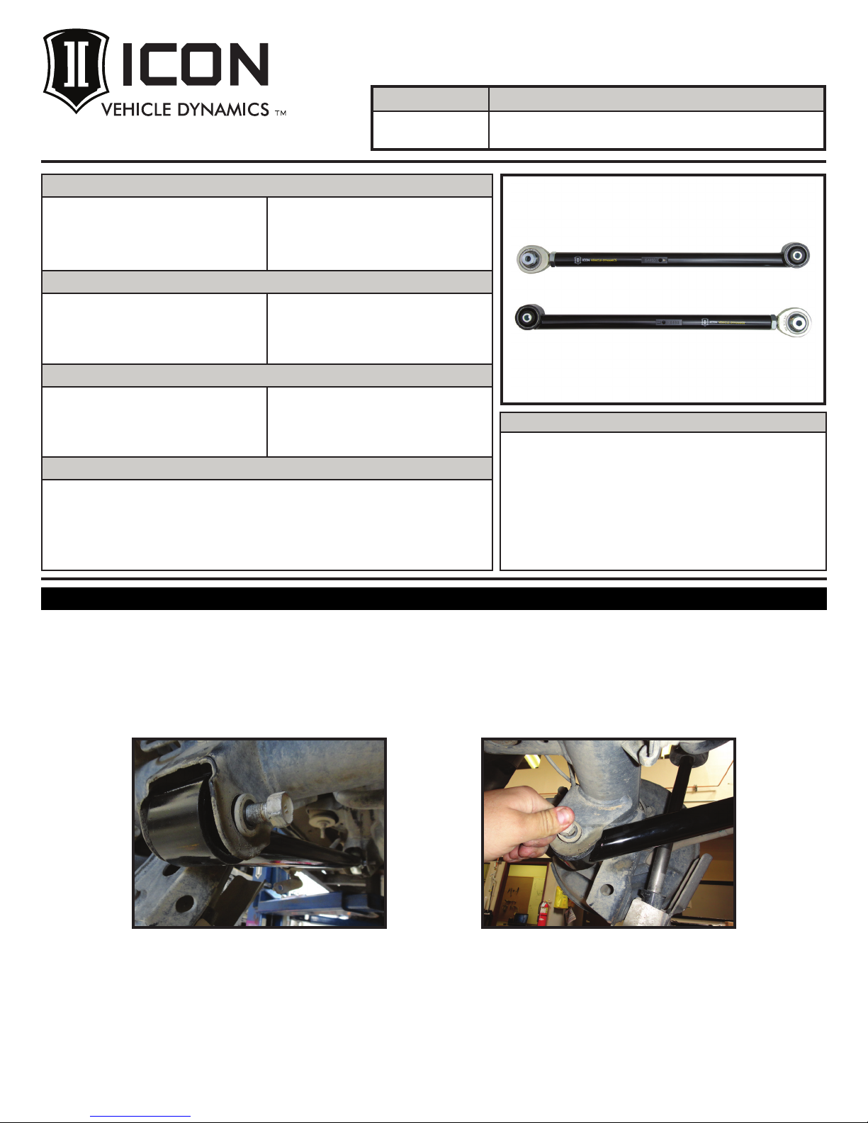
54000T
2007-UP FJ/4RUNNER TUBULAR LOWER
TRAILING ARM KIT
6-01-2016 REV.A
(1) 154400 07-UP FJ/4RUNNER TUBULAR LOWER
TRAILING ARM (DRVR)
(1) 154401 07-UP FJ/4-RUNNER TUBULAR LOWER
TRAILING ARM (PASS)
HARDWARE INCLUDED
(2) 127005 HEIM SPACER JM16 X .570 X 2.625
(2) 157430 HEIM SPACER JM16 X .570 X 2.075
(2) 295510 JM16-1T 1-14 RH ROD END F1 FIT
(2) 297102 GREASELESS PRESS IN BUSH 2.135 X
14.3MM X 58.85MM
(2) 605920 1-14 JAM NUT
TOOLS REQUIRED
JACK
JACK STANDS
TORQUE WRENCH
TECH NOTES
1. DO NOT EXCEED 3.5” FROM LINK FACE TO CENTERLINE OF ROD END.
2. BUSHINGS ARE GREASELESS AND DO NOT REQUIRE MAINTENANCE.
3. LOWER ARMS MOUNT SO THAT THE REAR BUSHING HOUSING IS TANGENT WITH THE TUBE ON
BOTTOM. IF MOUNTED UPSIDE DOWN, LINK TUBE WILL BIND ON AXLE HOUSING.
1.5” OPEN END WRENCH
12MM SOCKET / WRENCH
19MM SOCKET / WRENCH
21MM SOCKET / WRENCH
WARNING!
** READ ALL INSTRUCTIONS THOROUGHLY FROM START TO FINISH
BEFORE BEGINNING INSTALLATION! IF THESE INSTRUCTIONS ARE
NOT PROPERLY FOLLOWED SEVERE FRAME, SUSPENSION AND TIRE
DAMAGE MAY RESULT TO THE VEHICLE!
** ICON VEHICLE DYNAMICS RECOMMENDS THAT YOU EXERCISE
EXTREME CAUTION WHEN WORKING UNDER A VEHICLE THAT IS
SUPPORTED WITH JACK STANDS.
** ICON VEHICLE DYNAMICS RECOMMENDS ALL INSTALLTION TO
BE PERFORMED BY A PROFESSIONAL SHOP/SERVICE TECHNICIAN.
PRODUCT FAILURE CAUSED BY IMPROPER INSTALLATION WILL NOT BE
COVERED UNDER ICON’S WARRANTY POLICY.
INSTALLATION
1. Using a properly rated jack, raise the rear of the vehicle and support the frame rails with jack stands. Ensure the jack stands are
secure and set properly before lowering the jack. NEVER WORK UNDER AN UNSUPPORTED VEHICLE. Remove the rear wheels
NOTE: REMOVE AND REPLACE ONLY ONE FACTORY LINK ARM AT A TIME.
2. Lay ICON link arm over the factory link to set a starting point for adjustment (26.75”).
3. Use the factory hardware to install the link arm on the axle end using a 19mm socket/wrench. [Torque to factory spec]
[FIGURE 1 & 2]
FIG.2FIG.1
1
Page 2

. The pinion angle can be adjusted as desired once both links are installed. Do not adjust longer than 3.5”. [FIGURE 3]
4
FIG.3
5. Connect the link to the frame using the factory hardware with the short spacer towards the inside of the vehicle. This will move the
front link pivot points closer together on the frame to help correct roll-steer geometry on lifted vehicles. [FIGURE 4 & 5]
FIG.5FIG.4
6. Tighten jam nut using an 1.5” open end wrench. [Torque to 200 ft-lbs] Make sure the rod end is vertical as it is tightened.
7. Tighten the front bolt on the lower link arm using a 19mm socket/wrench [Torque to factory spec]. Fasten emergency brake mount
to the link arm with a 12mm socket/wrench using the factory hardware. [FIGURE 6]
FIG.6
8. Repeat steps on the opposite side.
9. Reinstall wheels and lower vehicle to the ground. [Torque to factory spec]
VERIFY ALL FASTENERS ARE PROPERLY TORQUED BEFORE DRIVING VEHICLE.
RETORQUE ALL NUTS, BOLTS AND LUGS AFTER 100 MILES AND PERIODICALLY THEREAFTER.
2
Page 3

ICON VEHICLE DYNAMICS LIMITED LIFETIME WARRANTY
ICON Vehicle Dynamics warrants to the original retail purchaser who owns the vehicle on which the product was originally
installed. ICON Vehicle Dynamics does not warrant the product for finish, alterations, modifications and/or installation contrary
to ICON Vehicle Dynamics instructions. ICON Vehicle Dynamics products are not designed, nor are they intended to be installed
on vehicles used in race applications, for racing purposes or for similar activities. (A “race” is defined as any contest between two
or more vehicles, or a contest of one or more vehicles against the clock, whether or not such contest is for a prize). This warranty
does not include coverage for police or taxi vehicles, race vehicles, or vehicles used for government or commercial purposes. Also
ICON Vehicle Dynamics’ obligation under this warranty is limited to the repair or replacement, at ICON Vehicle Dynamics’
discretion, of the defective product. Any and all costs of removal, installation or re-installation, freight charges and incidental or
consequential damages are expressly excluded from this warranty. Items that are subject to wear are not considered defective
ICON Vehicle Dynamics components must be installed as a complete kit as shown in our current application guide. Any
substitutions or exemptions of required components will immediately void the warranty. Some finish damage may happen to parts
This warranty is expressly in lieu of all other warranties expressed or implied. This warranty shall not apply to any product that has
excluded from this warranty are sales outside of the United States of America and Canada.
when worn and are not covered.
during shipping and is not covered under warranty.
been improperly installed, modified or customized subject to accident, negligence, abuse or misuse.
7929 Lincoln Ave. Riverside, CA 92504 Phone: 951.689.ICON Fax: 951.689.1016
www.iconvehicledynamics.com
FOLLOW US ON FACEBOOK!
3
 Loading...