

Page 1

INSTRUCTION MANUAL
The photo shows the
VHF transceiver
iF3032S
VHF TRANSCEIVERS
iF4032S
UHF TRANSCEIVERS
Page 2

IMPORTANT
EXPLICIT DEFINITIONS
READ ALL INSTRUCTIONS carefully and com-
pletely before using the transceiver.
SAVE THIS INSTRUCTION MANUAL — This
instruction manual contains important oper ating instructions
for the IC-F3032S VHF TRANSCEIVER and the IC-F4032S
UHF TRANSCEIVER.
This instruction manual includes some functions which are
usable only when they are pre-programmed by your dealer.
Ask your dealer for details.
Icom, Icom Inc. and the Icom logo are registered trademarks of Icom Incorporated (Japan) in Japan, the United States, the United Kingdom, Germany,
France, Spain, Russia and/or other countries.
i
WORD DEFINITION
RDANGER!
RWARNING!
CAUTION
NOTE
Personal death, serious injury or an explosion may occur.
Personal injury, fire hazard or electric
shock may occur.
Equipment damage may occur.
If disregarded, inconvenience only. No risk
of personal injury, fire or electric shock.
Page 3

PRECAUTIONS
DANGER! NEVER short the terminals of the battery
R
pack.
DANGER! Use and charge only specified Icom bat-
R
tery packs with Icom radios or Icom chargers. Only Icom battery packs are tested and approved for use with Icom radios
or charged with Icom chargers. Using third-party or counterfeit battery packs or chargers may cause smoke, fire, or
cause the battery to burst.
WARNING! NEVER hold the transceiver so that
R
the antenna is very close to, or touching exposed parts of
the body, especially the face or eyes, while transmitting. The
transceiver will perform best if the microphone is 5 to 10 cm
away from the lips and the transceiver is vertical.
WARNING! NEVER operate the transceiver with
R
a headset or other audio accessories at high volume levels.
Hearing experts advise against continuous high volume operation. If you experience a ringing in your ears, reduce the
volume level or discontinue use.
WARNING! NEVER operate the transceiver while
R
driving a vehicle. Safe driving requires your full attention—
anything less may result in an accident.
CAUTION: MAKE SURE the flexible antenna, bat-
tery pack and jack cover are securely attached to the transceiver, and that the antenna and battery pack are dry before
attachment. Exposing the inside of the transceiver to dust or
water will result in serious damage to the transceiver.
DO NOT operate the transceiver near unshielded electri-
cal blast ing caps or in an explosive atmosphere.
DO NOT
push [PTT] when not actually intending to transmit.
DO NOT use or place the transceiver in direct sunlight or
in areas with temperatures below –25°C or above +55°C.
The basic operations, transmission and reception of the
transceiver are guaranteed within the specified operating
temperature range. However, the LCD display may not be
operate correctly, or show an indication in the case of long
hours of operation, or after being placed in extremely cold
areas.
DO NOT modify the transceiver. The transceiver warranty does
not cover any problems caused by unauthorized modification.
DO NOT use harsh solvents such as benzine or alcohol
when cleaning, as they will damage the transceiver surfaces.
BE CAREFUL! The transceiver will become hot when
operating it continuously for long periods of time.
ii
Page 4

PRECAUTIONS (Continued)
BE CAREFUL! The IC-F3032S and IC-F4032S meet
IP67* requirements for dust-tight and waterproof protection.
However, once the transceiver has been dropped, dust-tight
and waterproof protection cannot be guaranteed because of
possible damage to the transceiver’s case or the waterproof
seal.
* Only when the jack cover or the optional HM-168LWP is
attached.
Even when the transceiver power is OFF, a slight current still
flows in the circuits. Remove the battery pack or batteries
from the trans ceiver when not using it for a long time. Otherwise, the installed battery pack or batteries will become exhausted, and will need to be recharged or replaced.
MAKE SURE to turn the transceiver power OFF before
connect ing the supplied/optional equipment.
iii
Page 5

TABLE OF CONTENTS
IMPORTANT .......................................................................... i
EXPLICIT DEFINITIONS ....................................................... i
PRECAUTIONS .................................................................... ii
FCC INFORMATION ........................................................... iii
TABLE OF CONTENTS ....................................................... iv
1 ACCESSORIES ...........................................................1–2
Supplied accessories ■ ................................................... 1
Accessory attachments ■ ................................................1
2 PANEL DESCRIPTION ................................................3–7
Front panel ■ ................................................................... 3
Function display ■ ...........................................................4
Programmable function keys ■ ........................................5
3 BASIC OPERATION ..................................................8–14
Turning power ON ■ ........................................................8
Channel selection ■ ........................................................9
Call procedure ■ ..............................................................9
Receiving and transmitting ■ .........................................10
User set mode ■ ............................................................12
Emergency Call ■ ..........................................................12
Priority A channel selection ■ ........................................ 13
Man Down Emergency Call ■ ........................................13
Stun function ■ ..............................................................13
Scrambler function ■ .....................................................13
MDC 1200 system operation ■ ..................................... 14
4 BATTERY CHARGING ............................................15–19
Caution ■ .......................................................................15
Optional battery chargers ■ ........................................... 17
5 OPTIONAL SWIVEL BELT CLIP ............................20–21
MB-93 contents ■ ..........................................................20
Attaching ■ ....................................................................20
Detaching ■ ...................................................................21
6 SPEAKER MICROPHONE ............................................22
Optional HM-168LWP description ■ ..............................22
Attachment ■ ................................................................. 22
7 OPTIONS .................................................................23–24
8 COUNTRY CODE LIST .................................................25
1
2
3
4
5
6
7
8
9
10
11
12
13
14
15
16
iv
Page 6
1
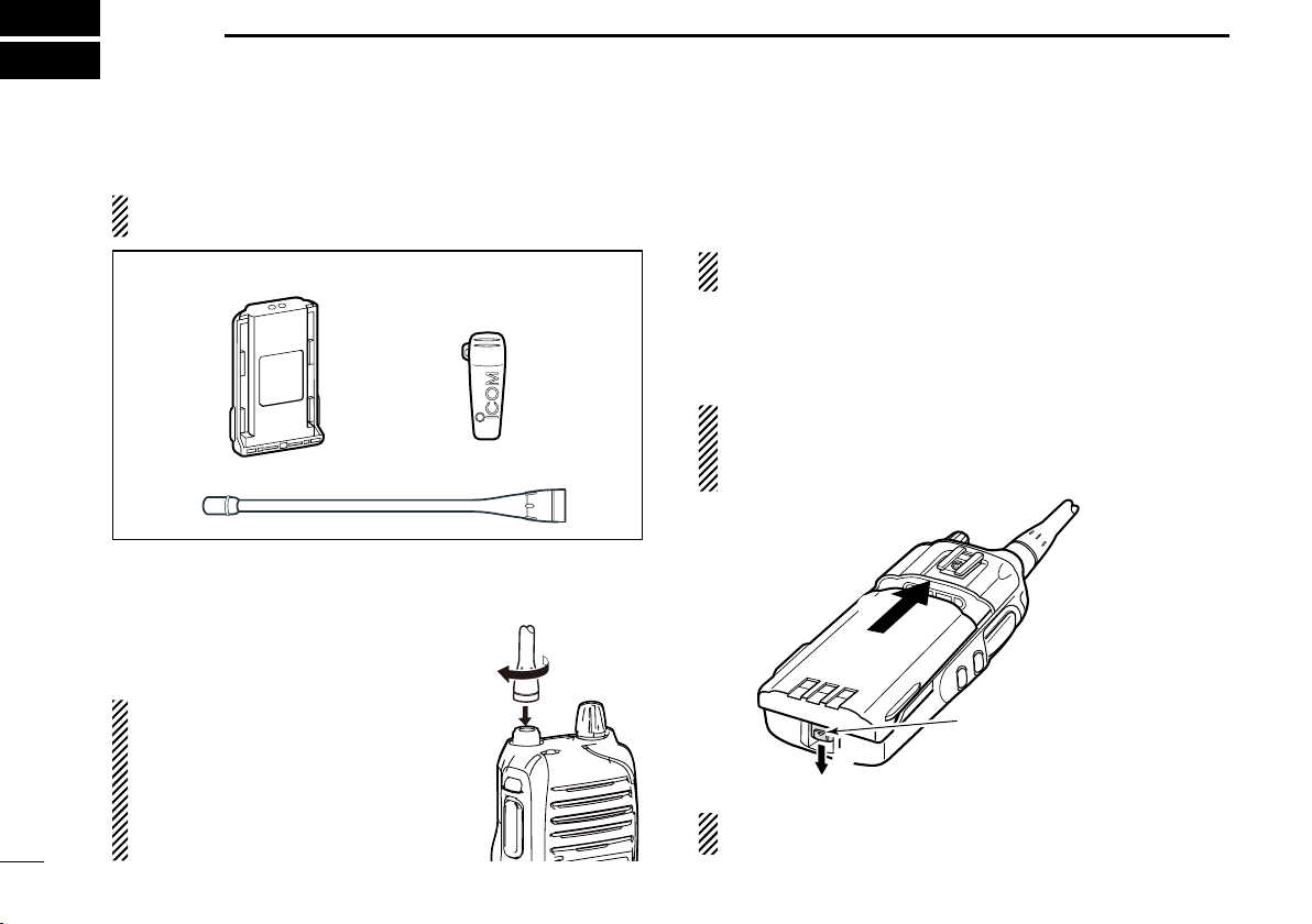
Flexible antenna
Battery pack
Belt clip
q
w
Battery release button
ACCESSORIES
Supplied accessories ■
NOTE: Some accessories are not supplied with depending
on versions.
Battery pack D
To attach the battery pack:
Slide the battery pack in the direction of the arrow (q) until
the battery release button makes a ‘click’ sound.
NOTE: Push on the bottom of the pack to make sure the
release button is firmly locked.
To release the battery pack:
Slide the battery release button in the direction of the arrow
(w) as shown below. The battery pack is then released.
NEVER release or attach the battery pack when the transceiver is wet or soiled. This may result water or dust getting into the transceiver/battery pack and may result in the
transceiver being damaged.
Accessory attachments ■
Flexible antenna D
Connect the supplied flexible antenna to
the antenna connector.
CAUTION:
• NEVER carry the transceiver by
holding the antenna.
• DO NOT connect the antenna other
than listed on page 24.
• Transmitting without an antenna
may damage the transceiver.
1
NOTE: Keep the battery terminals clean. It's a good idea
to regularly clean them.
Page 7
ACCESSORIES
q
w
w
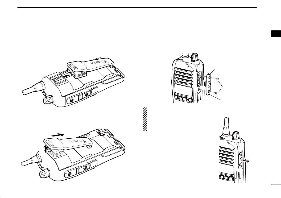
[MIC/SP] jack
Jack cover
q
q
q
w
1
Belt clip D
To attach the belt clip:
Release the battery pack if it is attached. q
w Slide the belt clip in the direction of the arrow until the belt
clip is locked and makes a ‘click’ sound.
To detach the belt clip:
Release the battery pack if it is attached. q
Pinch the clip ( w q), and slide the belt clip in the direction of
the arrow (w).
Jack cover D
To attach the jack cover:
q Attach the jack cover to the [MIC/SP] jack.
w Tighten the screws.
CAUTION:
• Attach the jack cover when the op-
tional speaker-microphone is not
used.
• Use the supplied screws only.
To detach the jack cover:
q Unscrew the screws using a phillips
screwdriver.
w Detach the jack cover for the speak-
er-microphone or headset connection.
1
2
Page 8
2
q
w
r
e
o
u
y
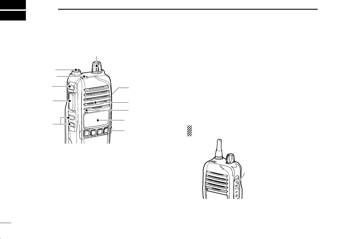
Microphone
Speaker
t
i
Jack cover
NOTE: Attach the jack
cover when the optional
equipment is not used.
See (p. 2) for details.
PANEL DESCRIPTION
Front panel ■
t DEALER-PROGRAMMABLE KEYS [Side2]/[Side3]
Desired functions can be programmed independently by
your dealer. (p. 5)
y DEALER-PROGRAMMABLE KEYS [P0] to [P3]
Desired functions can be programmed independently by
your dealer. (p. 5)
u FUNCTION DISPLAY (p. 4)
Displays a variety of information such as an operating
channel number/name, 2-tone code, DTMF numbers, selected function and so on.
i EXTERNAL MICROPHONE/SPEAKER JACK
Connect an optional speaker-microphone.
NOTE: Connect or disconnect the optional equipment
after the transceiver is turned OFF.
q ANTENNA CONNECTOR
Connects the supplied antenna.
w DEALER-PROGRAMMABLE KEY [Emer]
Desired function can be programmed by your dealer. (p. 7)
e DEALER-PROGRAMMABLE KEY [Side1]
Desired function can be programmed by your dealer.
(p. 5)
r PTT SWITCH [PTT]
Push and hold to transmit; release to receive.
3
o VOLUME CONTROL [VOL]
Rotate to turn the power ON/OFF and adjusts the audio
level.
Page 9
PANEL DESCRIPTION
yq iutrew
o
!0
2
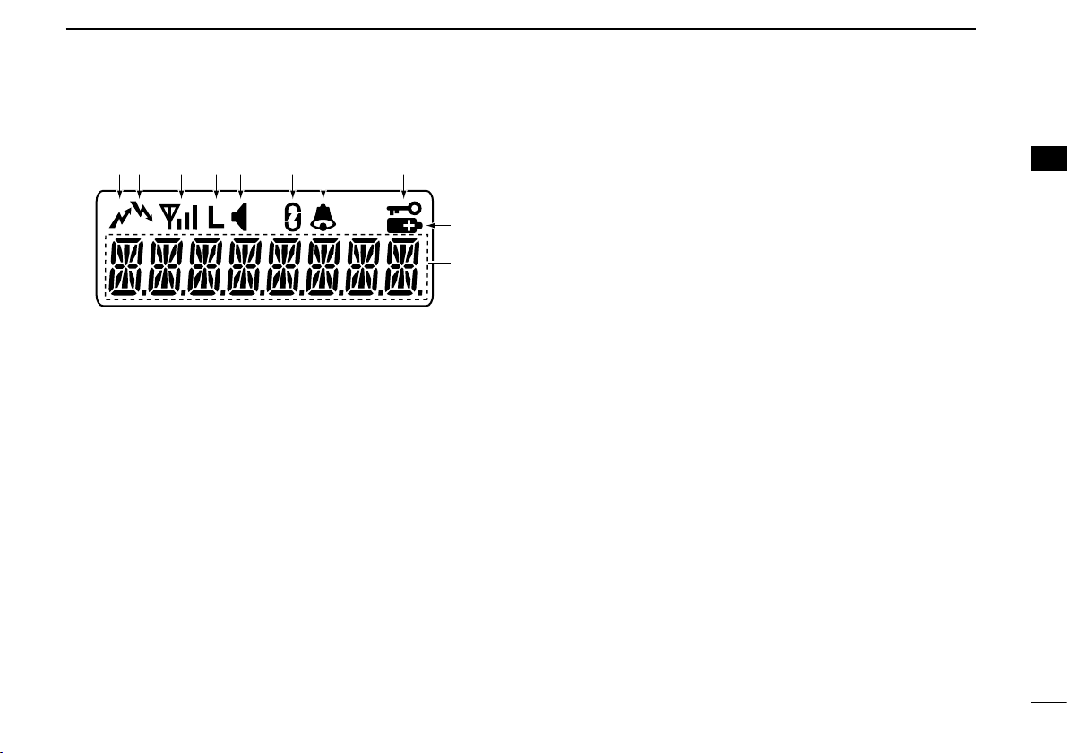
Function display ■
q TRANSMIT INDICATOR
Appears while transmitting.
w BUSY INDICATOR
Appears while the channel is busy.
e SIGNAL STRENGTH INDICATOR
Indicates relative signal strength level.
r LOW POWER INDICATOR
Appears when low output power is selected.
• When the battery power decreases to a specied level, low
power is selected automatically.
t AUDIBLE INDICATOR
➥ Appears when the channel is in the ‘audible’ (unmute)
condition.
Appears when the specified 2-tone code is received. ➥
y SCRAMBLER INDICATOR
Appears when the voice scrambler function is activated.
u BELL INDICATOR
Appears or blinks when the specific 2-tone code is re-
ceived, according to the pre-programming.
i KEY LOCK INDICATOR
Appears during the key lock function is ON.
o BATTERY INDICATOR
Appears or blinks when the battery power decreases to a
specified level.
!0 ALPHANUMERIC DISPLAY
Displays an operating channel number, channel name,
Set mode contents, DTMF code, etc.
1
2
3
4
5
6
7
8
9
10
11
12
13
14
15
16
4
Page 10

PANEL DESCRIPTION
2
Programmable function keys ■
The following functions can be assigned to [Emer], [Side1],
[Side2], [Side3], [P0], [P1], [P2] and [P3] programmable
function keys.
Consult your Icom dealer or system operator for details concerning your transceivers programming.
If the programmable function names are bracketed in the following explanations, the specific key is used to activate the
function depends on the programming.
CH UP AND DOWN KEYS
➥ Push to select an operating channel.
➥ Push to select a transmit code channel after pushing [TX
Code CH Select].
➥ Push to select a DTMF channel after pushing [DTMF Au-
todial].
➥ Push to select a scan group after pushing and holding
[Scan A Start/Stop]/[Scan B Start/Stop] for 1 second.
SIREN KEY
Push to emit a siren.
ZONE KEY
Push this key, then push [CH Up] or [CH Down] to select the
desired zone.
What is “zone”?— The desired channels are assigned
into a zone according to the intended use for grouping.
For example, ‘Staff A’ and ‘Staff B’ are assigned into a
“Business” zone, and ‘John’ and ‘Cindy’ are assigned into
a “Private” zone.
5
SCAN A KEY
➥ This key’s operation depends on the Power ON Scan set-
ting.
When the power ON scan function is turned OFF;
Push to start and cancel scanning operation. In case of
transmission during scan, scanning will be cancelled.
When the power ON scan function is turned ON;
Push to pause scanning, then resumes scanning after
passing a specified time period. In case of transmission
during scan, scanning will be cancelled.
➥ Push and hold this key for 1 second to indicate the scan
group, then push [CH Up] or [CH Down] to select the desired group.
SCAN B KEY
➥ Push to start and cancel scanning operation. In case of
transmission during scan, scanning will be paused. Then
resumes scanning after passing a specified time period.
➥ Push and hold this key for 1 second to indicate the scan
group, then push [CH Up] or [CH Down] to select the desired group.
PRIO A/B KEYS
➥ Push to select Priority A or Priority B channel.
➥ Push and hold [Prio A (Rewrite)] or [Prio B (Rewrite)] for 1
second to reassign the operating channel to Priority A or
Priority B channel.
Page 11

PANEL DESCRIPTION
2
SCAN ADD/DEL (TAG) KEY
➥ Push to add a channel to, or delete it from the current scan
list.
• When a channel is added to the current scan list, the display
shows “SCAN ON.” When a channel is deleted from the current
scan list, the display shows “SCAN OFF.” After showing “SCAN
ON” or “SCAN OFF,” the display shows the current scan list text.
➥ You can add a channel to, or delete it from the scan list
after selecting the list.
1. Hold down for 1 second to display the current scan list,
and then push [CH Up] or [CH Down] to select a desired
list.
2. Push this key to add a channel to, or delete it from the
selected list.
3. Hold down this key for 1 second to exit the scan list
selection mode.
➥ Push this key while a scan is paused on a channel, except
for primary or secondary channel, and then the channel is
deleted from the scan list.
• Depending on the setting, the deleted channel is added to the
scan list again after the scan is cancelled. (Nuisance Delete
function)
C.TONE CH ENT KEY
Push to select the continuous tone channel using [CH Up]/
[CH Down] to change the tone frequency/code setting. The
selected channel remains set as the continuous tone channel
until another channel is designated as such.
MR-CH 1/2/3/4 KEYS
Push to select memory channels 1 to 4 in the operating zone
directly.
MONI KEY
Mute and release the CTCSS (DTCS) or 2-tone squelch
mute. Open any squelch/deactivate any mute while pushing
and holding this key.
LOCK KEY
➥ Push and hold for 1 second to electronically lock all pro-
grammable keys except the following:
[Call] (incl. Call A and Call B), [Moni], [Emergency], [Sur-
veillance], [Siren], [Lone Worker] and [OPT 1/2/3].
➥
Push and hold for 1 second again to turn the lock function
OFF.
HIGH/LOW KEY
Push to select the transmit output power temporarily or permanently, depending on the presetting.
• Ask your dealer for the output power level for each selection.
OPT MOMENTARY KEYS
Controls the output signal level of the optional ports in the
optional unit connector while pushing and holding this key.
OPT OUT KEYS
Push to control the output signal level of the optional ports in
the optional unit connector.
SCRAMBLER FUNCTION
Push to toggle the voice scrambler function ON and OFF.
2
6
Page 12

PANEL DESCRIPTION
2
TALK AROUND KEY
Push to turn the talk around function ON and OFF.
• The talk around function equalizes the transmit frequency to the
receive frequency for transceiver-to-transceiver communication.
WIDE/NARROW KEY
Push to toggle the IF bandwidth between wide and narrow.
DTMF AUTODIAL KEY
➥ Push to enter the DTMF channel selection mode. Then se-
lect the desired DTMF channel using [CH Up]/[CH Down].
➥ After selecting the desired DTMF channel, push this key to
transmit the DTMF code.
RE-DIAL KEY
Push to transmit the last-transmitted DTMF code.
EMERGENCY KEY
Push and hold to transmit the emergency call.
• The transceiver can transmit the emergency call silently or audibly
depending on the presetting. Ask your dealer for details.
• When the emergency call transmits with beeps, the emergency
text is displayed on the LCD if programmed.
• If you want to cancel the emergency call, push and hold the key
again before transmitting the call.
• The emergency call is transmitted one time only or repeatedly until
receiving a control code, depending on the presetting.
SURVEILLANCE KEY
Push to turn the surveillance function ON or OFF.
When this function is turned ON, the beep is not emitted and
the LCD backlight does not light when a signal is received or
a key is pushed, etc.
CALL KEYS
Push to transmit a 2-tone.
• Call transmission is necessary before you call another station depending on your signaling system.
• [Call A] and/or [Call B] may be available when your system employs selective ‘Individual/Group’ calls. Ask your dealer which call
is assigned to each key.
LONE WORKER KEY
Push to turn the Lone Worker function ON or OFF.
• If the Lone Worker function is activated, the Emergency function
is automatically turned ON after the specified time period has
passed with no operation is performed.
TX CODE CHANNEL UP/DOWN KEYS
Push to select a TX code channel directly.
TX CODE CHANNEL SELECT KEY
Push to enter the ID code channel selection mode directly.
Then set the desired channel using [CH Up]/[CH Down].
(p. 11)
USER SET MODE KEY
➥ Push and hold for 1 second to enter user set mode.
• During in the user set mode, push this key to select an item that
is enabled by your dealer, and change the value or condition by
pushing [CH Up] or [CH Down].
➥ Push and hold this key for 1 second again to exit user set
mode.
User set mode is also available via the ‘Power ON function.’
Refer to page 8 also.
7
Page 13

BASIC OPERATION
KEY
NUMBER
0
5
4
9
3
8
2
7
1
6
[Side3]
[P0]/[P1]/
[P2]/[P3]
Side3
[VOL]
[VOL]
[PTT]
[Emer]
Dry battery mode
Appears
3
Turning power ON ■
Prior to using the transceiver for the first time, the battery
pack must be fully charged for optimum life and operation.
(p. 17)
Rotate [VOL] to turn the power ON. q
w If the transceiver is programmed for a start up password,
input the digit codes as directed by your dealer.
• 10-keypad can be used for password input depending on version:
• The keys in the table below can be used for password input:
• The transceiver detects numbers in the same block as identi-
cal. Therefore “01234” and “56789” are the same.
e When the “PASSWORD” indication does not clear after
inputting 4 digits, the input code number may be incorrect.
Turn the power off and start over in this case.
Battery type selection D
The battery type must be selected according to the attaching
battery type when turning the transceiver ON.
Ask your dealer for details.
Turn the power OFF. q
While pushing and holding [Emer] and [PTT], turn the w
power ON with rotating [VOL] to toggle the attaching battery type.
• After the display appears, release [Emer] and [PTT].
• “DRY BATT” is displayed for about 3 seconds then “L” appears
when the battery case operation is selected. In this case, the
transmit output power is low.
• “LI-ION” is displayed for about 3 seconds when the Lithium-ion
battery operation is selected.
1
2
3
4
5
6
7
8
9
10
11
12
13
14
15
16
8
Page 14

BASIC OPERATION
Selective calling
Non-selective calling
3
Channel selection ■
Several types of channel selections are available. Methods
may differ according to your system set up.
NON-ZONE TYPE:
Push [CH Up] or [CH Down] to select the desired operating
channel, in sequence; or, push one of [MR-CH 1] to [MR-CH 4]
keys to select a channel directly.
ZONE TYPE:
Push [Zone], then push [CH Up] or [CH Down] to select the
desired zone.
AUTOMATIC SCAN TYPE:
Channel setting is not necessary for this type. When turning power ON, the transceiver automatically starts scanning.
Scanning stops when receiving a call.
Call procedure ■
When your system employs tone signaling (excluding CTCSS
and DTCS), the call procedure may be necessary prior to voice
transmission. The tone signaling employed may be a selective
calling system which allows you to call specific station(s) only
and prevent unwanted stations from contacting you.
q Select the desired TX code channel or 2-tone code according to your System Operator’s instructions.
• This may not be necessary depending on programming.
• Refer to page 13 for selection.
w Push the call key (assigned to one of the dealer programmable keys: [Emer], [Side1], [Side2], [Side3], [P0], [P1],
[P2] and [P3]) or [PTT].
After transmitting a 2-tone code, the remainder of your e
communication can be carried out in the normal fashion.
9
Page 15

BASIC OPERATION
3
Receiving and transmitting ■
CAUTION: Transmitting without an antenna may damage
the transceiver. See page 1 for accessory attachments.
Receiving:
Rotate [VOL] to turn the power ON. q
Push [CH Up] or [CH Down] to select the conventional sys- w
tem channel, in sequence.
e When receiving a call, adjust the audio output level to a
comfortable listening level.
NOTE: When a matched RX code signal is received, audio
from the microphone is automatically transmitted for a
specified time period.*
*
Depending on the presetting. Ask your dealer for details.
Transmitting:
Wait for the channel to become clear to avoid interference.
Push [Call] when initiating a call from your side. q
•
Coded audio may be heard from the transceiver, then “ ” appears.
• This operation may not be necessary depending on your signaling system. Ask your dealer for details.
While pushing and holding [PTT], speak into the micro- w
phone at a normal voice level.
Release [PTT] to return to receive. e
IMPORTANT: To maximize the readability of your signal;
1. Pause briefly after pushing [PTT].
2. Hold the microphone 5 to 10 cm from your mouth, then speak
into the microphone at a normal voice level.
Transmitting notes D
• Transmit inhibit function
The transceiver has several inhibit functions which restrict
transmission under the following conditions:
- The channel is in mute condition (‘Inaudible’ condition;
“
” does not appear.)
- The channel is busy.
- Un-matched (or matched) CTCSS is received.
(Depending on the presetting.)
- The selected channel is a ‘receive only’ channel.
• Time-out timer
After continuous transmission for the pre-programmed time
period, the time-out timer is activated, causing the transceiver to stop transmitting.
• Penalty timer
Once the time-out timer is activated, transmission is further
inhibited for a period determined by the penalty timer.
• PTTID call
The transceiver sends the ID code (DTMF or digital ANI) automatically when [PTT] is pushed (beginning of transmission)
and released (end of transmission) depends on the setting.
3
10
Page 16

BASIC OPERATION
3
TX code channel selection D
If the transceiver has [TX Code CH Select] assigned to it,
the indication can be toggled between the operating channel
number (or name) and TX code channel number (or name).
When the TX code channel number (or name) is displayed,
[CH Up] or [CH Down] selects the TX code channel.
USING [TX CODE CH SELECT] KEY:
Push [TX Code CH Select]— a TX code channel number q
(or name) appears.
w Push [CH Up] or [CH Down] to select the desired TX code
channel.
• Push [TX Code CH Select] again to return to the operating
channel number indication.
Push [Call] to transmit the selected TX code. e
USING [TX CODE CH UP]/[TX CODE CH DOWN] KEY:
If the transceiver has [TX Code CH Up] or [TX Code CH
Down] assignment, the programmed TX code channel can
be selected directly when pushed.
DTMF transmission D
If the transceiver has [DTMF Autodial] assigned to it, the
automatic DTMF transmission function is available. Up to 8
DTMF channels are available.
TO SELECT A TX CODE:
Push [DTMF Autodial]— a DTMF channel appears. q
w Push [CH Up] or [CH Down] to select the desired DTMF
channel.
Push [DTMF Autodial] to transmit the DTMF code in the e
selected DTMF channel.
11
Page 17

BASIC OPERATION
3
User set mode ■
User set mode is accessed at power ON and allows you to
set seldom-changed settings. In this case you can “customize” the transceiver operation to suit your preferences and
operating style.
Entering the user set mode:
q While pushing and holding [Side2] and [Side3], rotate
[VOL] to turn the power ON. Then, push and hold [P0] for
1 second to enter user set mode.
w Push [P0] several times to select the appropriate item.
Then push [CH Up] or [CH Down] to set the desired level/
condition.
•
Available set mode functions are Backlight, Beep, Beep
Level, SQL Level, Mic Gain, Battery Voltage, Signal
Moni and Lone Worker.
Rotate [VOL] to turn the power OFF to exit user set e
mode.
NOTE: User set mode is also available via a programma-
ble function key. Refer to “USER SET MODE KEY.” (p. 7)
Emergency Call ■
When [Emergency] is pushed for the specified time period*, the
emergency signal is transmitted once, or repeatedly, on the specified
emergency channel.
A repeat emergency signal is automatically transmitted until the
transceiver receives an acknowledgement signal, or you turn the
transceiver power OFF.
When no emergency channel is specified, the signal is transmitted
on the previously selected channel.
If you want to cancel the emergency call, hold down [Emergency]
again before transmitting the call.
If your transceiver is programmed for Silent operation, you can transmit an Emergency call without the beep sounding and the LED indi-
cator lighting.
IMPORTANT: It is recommended to set an emergency
channel individually to provide the certain emergency call
operation.
* Depending on the presetting. Ask your dealer for details.
D NOTES
Depending on the presetting, the following functions are automatically activated. Ask your dealer for details.
• Auto TX function
After the emergency call transmission, audio from the microphone is automatically transmitted for a specified time period.*
• Auto RX function
After the emergency call transmission, the transceiver stands
by in the audible mode for the specified time period.*
3
12
Page 18

BASIC OPERATION
3
Priority A channel selection ■
Depending on the presetting, the Priority A channel is selected each time the transceiver power is turned ON.
Man Down Emergency Call ■
This function requires the optional UT-124R m a n d o w n u n i t .
When the transceiver has been left in a horizontal position for
the specified time period*, the transceiver enters the emergency mode, and then the countdown starts.
After the specified time period* has passed, an emergency
call is automatically transmitted once, or repeatedly.
If the transceiver is placed in a vertical position before the first
transmission, the transceiver exits the emergency mode and
the emergency call is cancelled.
IMPORTANT: It is recommended to set an emergency
channel individually to provide the certain emergency call
operation.
* Depending on the presetting. Ask your dealer for details.
Stun function ■
When the specified ID, set as a stun ID or kill ID, is received,
the stun function is activated.
When the stun ID is received, the transceiver becomes unusable. Entering of the password (p. 8) or receiving a specified
ID, set as a revive ID, is necessary to operate the transceiver
again in this case.
When the kill ID is received, the transceiver switches to the
cloning required condition. Cloning the transceiver is necessary to operate the transceiver again in this case.
Stun function is also available with the MDC 1200 signaling
system. (p. 14)
Scrambler function ■
The voice scrambler function provides private communication between stations. The optional Rolling or Non-rolling
type can be available.
Push [Scrambler] to turn the scrambler function ON. q
• “ ” appears.
w Push [Scrambler] again to turn the scrambler function
OFF.
• “ ” disappears.
13
Page 19
BASIC OPERATION
3
MDC 1200 system operation ■
The MDC 1200 signaling system enhances your transceiver’s capabilities. It allows PTT ID*, Emergency signaling, and
receiving Radio Check. Also, the dispatcher can stun and revive transceivers on the system.
* When [PTT] is pushed and/or released, the transceiver transmits
your station ID.
Transmitting an Emergency Call D
The MDC 1200 system’s Emergency feature can be accessed using the [Emergency] key (p. 7). The transceiver will
send an Emergency MDC 1200 system command once, or
repeatedly for a programmed number of times until it receives
the acknowledgement signal.
The emergency call can be transmitted without a beep sound
depending on how the emergency function is programmed.
Ask your dealer for details.
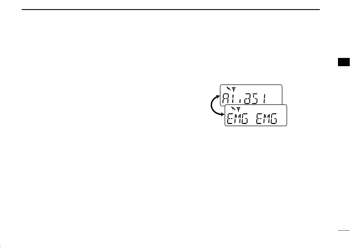
Receiving an Emergency Call D
When an emergency call is received; q
• Beeps sound.
• The calling station alias and “EMG EMG” are displayed alter-
nately.
w Turn power OFF, change the channel, push [PTT] for replying the call, etc. to stop the beep and display indication.
Receiving a Stun and Revive D
The dispatcher can send MDC 1200 system signals that will
stun or revive your transceiver. If a Stun command is received that matches your station ID, the transceiver will display “SORRY” (default) and you can not receive or transmit.
When a Revive command is received that matches your station ID, normal operation is restored.
3
14
Page 20

4
BATTERY CHARGING
Caution ■
Misuse of Lithium-ion batteries may result in the following
hazards: smoke, fire, or the battery may rupture. Misuse
can also cause damage to the battery or degradation of
battery performance.
R DANGER! Use and charge only specified Icom battery
packs with Icom radios or Icom charger. Only Icom battery
packs are tested and approved for use and charge with Icom
radios or Icom charger. Using third-party or counterfeit battery packs or charger may cause smoke, fire, or cause the
battery to burst.
Battery caution
R DANGER! DO NOT hammer or otherwise impact the bat-
tery. Do not use the battery if it has been severely impacted
or dropped, or if the battery has been subjected to heavy
pressure. Battery damage may not be visible on the outside
of the case. Even if the surface of the battery does not show
cracks or any other damage, the cells inside the battery may
rupture or catch fire.
R DANGER! NEVER use or leave battery packs in areas
with temperatures above +60˚C. High temperature buildup in
the battery, such as could occur near fires or stoves, inside
a sun heated car, or in direct sunlight may cause the battery
to rupture or catch fire. Excessive temperatures may also degrade battery performance or shorten battery life.
R DANGER! DO NOT expose the battery to rain, snow, sea-
water, or any other liquids. Never charge or use a wet battery.
If the battery gets wet, be sure to wipe it dry before using.
R DANGER! NEVER incinerate used battery packs since in-
ternal battery gas may cause them to rupture, or may cause
an explosion.
R DANGER! NEVER solder the battery terminals or NEVER
modify the battery pack. This may cause heat generation,
and the battery may rupture, emit smoke or catch fire.
R DANGER! Use the battery only with the transceiver for
which it is specified. Never use a battery with any other
equipment, or for any purpose that is not specified in this instruction manual.
R DANGER! If fluid from inside the battery gets in your eyes,
blindness can result. Rinse your eyes with clean water, without rubbing them, and see a doctor immediately.
15
Page 21

BATTERY CHARGING
4
1
R WARNING! Immediately stop using the battery if it emits
an abnormal odor, heats up, or is discolored or deformed. If
any of these conditions occur, contact your Icom dealer or
distributor.
R WARNING! Immediately wash, using clean water, any
part of the body that comes into contact with fluid from inside
the battery.
R WARNING! NEVER put the battery in a microwave oven,
high-pressure container, or in an induction heating cooker.
This could cause a fire, overheating, or cause the battery to
rupture.
CAUTION: Always use the battery within the specified temperature range, –20˚C to +55˚C. Using the battery out of its
specified temperature range will reduce the battery’s performance and battery life.
CAUTION: Shorter battery life could occur if the battery is
left fully charged, completely discharged, or in an excessive
temperature environment (above +50˚C) for an extended
period of time. If the battery must be left unused for a long
time, it must be detached from the radio after discharging.
You may use the battery until the remaining capacity is about
half, then keep it safely in a cool dry place with the temperature range as below:
–20˚C to +50˚C (within a month)
–20˚C to +35˚C (within three months)
Charging caution D
R DANGER! NEVER charge the battery pack in areas with
extremely high temperatures, such as near fires or stoves,
inside a sun heated car, or in direct sunlight. In such environments, the safety/protection circuit in the battery will activate,
causing the battery to stop charging.
R WARNING! NEVER charge or leave the battery in the bat-
tery charger beyond the specified time for charging. If the
battery is not completely charged by the specified time, stop
charging and remove the battery from the battery charger.
Continuing to charge the battery beyond the specified time
limit may cause a fire, overheating, or the battery may rupture.
R WARNING! NEVER insert the transceiver (battery at-
tached to the transceiver) into the charger if it is wet or soiled.
This could corrode the battery charger terminals or damage
the charger. The charger is not waterproof.
CAUTION: NEVER charge the battery outside of the specified temperature range: BC-160 and BC-171 (0˚C to +45˚C).
BC-119N and BC121N (+10˚C to +40˚C). Icom recommends
charging the battery at +20˚C. The battery may heat up or
rupture if charged out of the specified temperature range.
Additionally, battery performance or battery life may be reduced.
2
3
4
5
6
7
8
9
10
11
12
13
14
15
16
16
Page 22

BATTERY CHARGING
AC adapter
(Not supplied with
some versions.)
Optional OPC-515L
(for 13.8 V power
source) or CP-23L
(for 12 V cigarette
lighter socket) can
be used instead of
the AC adapter.
*
TransceiverBattery
pack
Tu rn power OFF
CAUTION: NEVER connect the OPC515L to a power source using reverse
polarity. This will ruin the battery charger.
White line: Black line
:
*
4
Optional battery chargers ■
Rapid charging with the BC-160 D
The optional BC-160 provides rapid charging of the Li-ion
battery pack.
• An AC adapter (may be supplied with BC-160 depending on version) or the DC power cable (OPC-515L/CP-23L) is additionally
required.
17
Regular charging with the BC-171 D
The optional BC-171 provides regular charging of the Li-ion
battery pack.
• An AC adapter (may be supplied with BC-171 depending on version) or the DC power cable (OPC-515L/CP-23L) is additionally
required.
Page 23

BATTERY CHARGING
Screws supplied
with the charger
adapter
AD-106
Connectors
Plugs
AD-106 charger
adapter is installed
in BC-119N.
AC adapter
(Not supplied with
some versions.)
Optional OPC-515L
(for 13.8 V power
source) or CP-23L
(for 12 V cigarette
lighter socket) can
be used instead of
the AC adapter.
Transceiver
Battery
pack
Tu rn power OFF
CAUTION: NEVER connect the OPC515L to a power source using reverse
polarity. This will ruin the battery charger.
White line: Black line
:
*
*
4
AD-106 installation D
The AD-106 c h a r g e r a d a p t e r must be installed into the BC119N or BC-121N before battery charging.
➥ Connect the AD-106
BC-121N as below, then install the AD-106 into the holder space of the BC-119N or BC-121N with the supplied
screws.
* This illustration is described with the BC-119N.
c h a r g e r a d a p t e r and the BC-119N/
Rapid charging with the BC-119N+AD-106 D
The optional BC-119N provides rapid charging of the Li-ion
battery pack. The following items are additionally required.
• AD-106 charger adapter
• An AC adapter (may be supplied with BC-119N depending on ver-
sion) or the DC power cable (OPC-515L/CP-23L).
1
2
3
4
5
6
7
8
9
10
11
12
13
14
15
16
18
Page 24

Battery
pack
AD-106 charger
adapters are installed
in each slot.
AC adapter
(Purchased
separately)
Transceiver
DC power cable (OPC-656)
(Connect with the DC power supply; 13.8 V/at least 7 A)
*About the OPC-656
Red line : Black line :
Tu rn power OFF
Guide rail
Tabs
BATTERY CHARGING
4
Rapid charging with the BC-121N+AD-106 D
The optional BC-121N allows up to 6 Li-ion battery packs to
be charged simultaneously. The following items are additionally required.
• Six AD-106 charger adapters
•
An optional AC adapter or the DC power cable (OPC-656)
IMPORTANT: Battery charging caution
Ensure the guide tabs on the battery pack are correctly
aligned with the guide rails inside the charger adapter.
(This illustration is described with the BC-160.)
19
Page 25

OPTIONAL SWIVEL BELT CLIP
q w
Once the transceiver is locked in place,
it will swivel 360 degrees.
5
MB-93 contents ■
q Belt clip ...........................................................................1
w Base clip .........................................................................1
Qt y.
Attaching ■
Release the battery pack if it is attached. (p. 2) q
w Slide the base clip in the direction of the arrow until the
base clip is locked and makes a ‘click’ sound.
r Clip the belt clip to a part of your belt. And insert the trans-
ceiver into the belt clip until the base clip inserted fully into
the groove.
t Once the transceiver is locked in place, it swivels as illus-
trated below.
1
2
3
4
5
6
7
8
9
10
11
12
13
14
15
16
Attach the battery pack. (p. 2) e
20
Page 26
OPTIONAL SWIVEL BELT CLIP
q
w
5
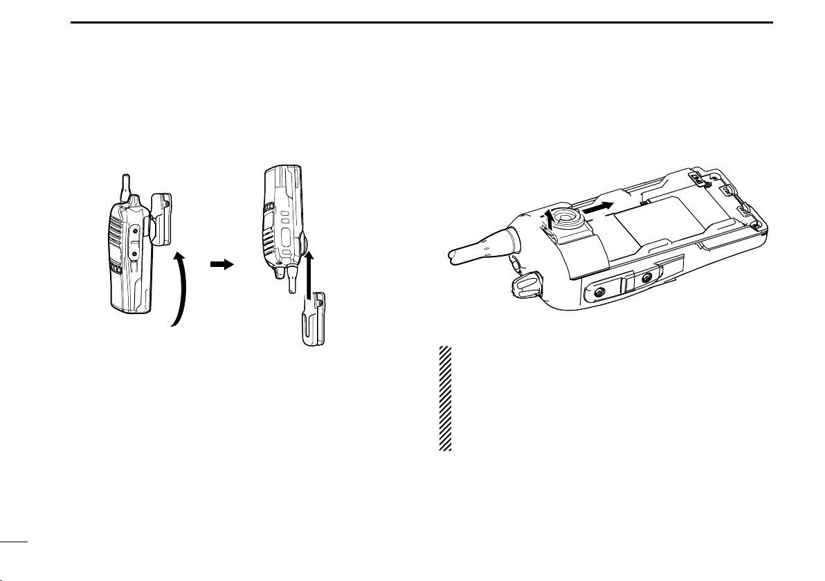
Detaching ■
q Turn the transceiver upside down in the direction of the
arrow and pull out from the belt clip.
Release the battery pack if it is attached. (p. 2) w
e Pinch the clip (q), and slide the base clip in the direction
of the arrow (w).
CAUTION:
HOLD THE TRANSCEIVER TIGHTLY, WHEN HANGING
OR DETACHING THE TRANSCEIVER FROM THE BELT
CLIP.
Otherwise the transceiver may not be attached to the
holder or swivel properly if the transceiver is accidentally
dropped and the base clip is scratched or damaged.
21
Page 27

SPEAKER MICROPHONE
Alligator type clip
To attach the speaker-mic.
to your shirt or collar, etc.
PTT switch
Transmits while pushed
Receives while released
Microphone
Speaker
Turn the transceiver power
OFF when connecting the
HM-168LWP.
Hand tighten
CAUTION: Attach the connector snugly.
A loose connection will allow water intrusion into the
connector.
6
Optional HM-168LWP description ■
NEVER immerse the connector in water. If the connector
becomes wet, be sure to dry it BEFORE attaching it to the
transceiver.
NOTE: The microphone is located as shown in the dia-
gram above. To maximize the readability of your transmitted signal (voice), hold the microphone approximately 5
to 10 cm from your mouth, and speak in a normal voice
level.
Attachment ■
Attach the connector of the speaker-microphone into the [SP
MIC] jack on the transceiver and tighten the screws with fingers.
NOTE: Use only your fingers instead of tools to tighten
the screws.
IMPORTANT: Keep the [SP MIC] jack cover attached to
the transceiver when the speaker-microphone is not in
use.
1
2
3
4
5
6
7
8
9
10
11
12
13
14
15
16
22
Page 28

7
OPTIONS
BATTERY PACK D
Battery pack Voltage Capacity Battery life*
BP-232WP 7.4 V
1
*
When the power save function is turned ON, and the operating
periods are calculated under the following conditions;
TX : RX : standby = 5 : 5 : 90
*2 Operating period depends on the alkaline cells used.
2250 mAh (min.)
2300 mAh (typ.)
17.5 hrs.
1
CHARGERS D
• BC-119N d e s k t o p c h a r g e r + AD-106 c h a r g e r a d a p t e r
+ BC-145S
For rapid charging of battery packs. An AC adapter is sup-
plied with the charger depending on versions.
Charging time: approximately 3 hours when BP-232WP is at-
• BC-121N m u l t i -c h a r g e r + AD-106 c h a r g e r a d a p t e r (6 pcs.)
+ BC-157S
For rapid charging of up to 6 battery packs (six AD-106’s
are required) simultaneously. An AC adapter should be purchased separately.
Charging time: approximately 3 hours when BP-232WP is at-
• BC-160 d e s k t o p c h a r g e r + BC-145S a c a d a p t e r
For rapid charging of battery packs. An AC adapter is sup-
plied with the charger depending on versions.
Charging time: approximately 3 hours when BP-232WP is at-
a c a d a p t e r
tached.
a c a d a p t e r
tached.
tached.
• BC-171 d e s k t o p c h a r g e r + BC-147S ac a d a p t e r
An AC adapter is supplied with the charger depending on
versions.
Charging time: approximately 10 hours when BC-232WP is at-
tached.
DC CABLES D
• CP-23L c i g a r e t t e l i g h t e r c a b l e
Allows charging of the battery pack through a 12 V cigarette
lighter socket. (For BC-160/BC-171/BC-119N)
• OPC-515L/OPC-656
Allows charging of the battery pack using a 13.8 V power
source instead of the AC adapter.
OPC-515L: For BC-160/BC-171/BC-119N
OPC-656 : For BC-121N
d c p o w e r c a b l e s
BELT CLIPS D
• MB-93 s w i v e l b e l t c l i p
• MB-94 b e l t c l i p
Exclusive alligator-type belt clip. The same as supplied with
the transceiver.
• MB-96N/96F
l e a t h e r b e l t h a n g e r
23
Page 29

OPTIONS
7
OPTIONAL UNITS D
• UT-96R 5 t o n e u n i t
• UT-108R d t m f d e c o d e r u n i t
Provides pager and code squelch capabilities.
• UT-109R /UT-110R*
Non-rolling type (UT-109R)/Rolling type (UT-110R)* voice
scrambler unit provides higher communication security.
*You can use the UT-110R as Non-rolling type.
• UT-124R
Provides measure of safety when working in a hazardous
environment, etc.
m a n d o w n u n i t
v o i c e sc r a m b l e r u n i t s
OTHER OPTIONS D
•
HM-168LWP s p e a k e r -m i c r o p h o n e
Combination speaker-microphone that provides convenient
operation while hanging the transceiver from your belt.
• FA-SC25V/FA-SC55V/
FA-SC25U/FA-SC57U/FA-SC62V/FA-SC63V
FA-SC25V: 136–150 MHz FA-SC55V: 150–174 MHz
FA-SC25U: 400–430 MHz FA-SC57U: 430–470 MHz
FA-SC62V: 150–160 MHz FA-SC63V: 155–165 MHz
• FA-SC56VS/FA-SC57VS/FA-SC73US
FA-SC56VS: 150–162 MHz FA-SC57VS: 160–174 MHz
FA-SC73US: 450–490 MHz
• FA-SC61VC/FA-SC61UC
FA-SC61VC: 136–174 MHz FA-SC61UC: 380–520 MHz
c u t a n t e n n a s
a n t e n n a s
s t u b b y a n t e n n a s
Some options may not be available in some countries. Ask
your dealer for details.
Approved Icom optional equipment is designed for optimal
performance when used with an Icom transceiver.
Icom is not responsible for the destruction or damage to an
Icom transceiver in the event the Icom transceiver is used with
equipment that is not manufactured or approved by Icom.
1
2
3
4
5
6
7
8
9
10
11
12
13
14
15
16
24
Page 30

8
ISO 3166-1
Country Codes Country Codes
1
Austria
2
Belgium
3
Bulgaria
4
Croatia
5
Czech Republic
6
Cyprus
7
Denmark
8
Estonia
9
Finland
10
France
11
Germany
12
Greece
13
Hungary
14
Iceland
15
Ireland
16
Italy
17
Latvia
COUNTRY CODE LIST
AT
18
BE
BG
HR
CZ
CY
DK
EE
FI
FR
DE
GR
HU
IS
IE
IT
LV
Liechtenstein
19
Lithuania
20
Luxembourg
21
Malta
22
Netherlands
23
Norway
24
Poland
25
Portugal
26
Romania
27
Slovakia
28
Slovenia
29
Spain
30
Sweden
31
Switzerland
32
Turkey
33
United Kingdom
LI
LT
LU
MT
NL
NO
PL
PT
RO
SK
SI
ES
SE
CH
TR
GB
25
Page 31

MEMO
1
1
2
2
3
3
4
4
5
5
6
6
7
7
8
9
9
10
10
11
11
12
12
13
13
14
14
15
15
16
16
Page 32

< Intended Country of Use >
AT
FI
IT
PL
GB
RO
BE
FR
LV
PT
IS
TR
CY
DE
LT
SK
LI
HR
CZ
GR
LU
SI
NO
DK
HU
MT
ES
CH
EE
IE
NL
SE
BG
A-6999D-1EU
Printed in Japan
© 2012 Icom Inc.
Printed on recycled paper with soy ink.
1-1-32 Kamiminami, Hirano-ku, Osaka 547-0003, Japan
 Loading...